system configuration of intelligent parking assistant systemweb.yonsei.ac.kr/hgjung/ho gi jung...
TRANSCRIPT

SYSTEM CONFIGURATION OF INTELLIGENT PARKING ASSISTANT SYSTEM
Ho Gi Jung*, Chi Gun Choi, Dong Suk Kim, Pal Joo YoonMANDO Corporation
ZIP 446-901, 413-5, Gomae-Dong, Giheung-Gu, Yongin-Si, Kyonggi-Do, Korea Tel.: +82-31-300-5253
E-mail: {hgjung, chigun, greenhupa, pjyoon}@mando.com ABSTRACT This paper describes the configuration of currently developed IPAS (Intelligent Parking Assistant System). IPAS allows driver to designate target position by three complimentary methods: monocular vision based parking slot marking recognition, ultrasonic sensor based parallel parking slot recognition, and drag&drop GUI (Graphical User Interface). IPAS generates an optimal path to reach the designated target position. During parking operations, IPAS estimates ego-vehicle pose using ESP (Electric Stability Program) sensors such as wheel speed sensors, braking pedal switch and steering angle sensor. IPAS automatically controls braking and steering to achieve planned trajectory by sending required actuations to ESP and EPS (Electric Power Steering) via CAN. Furthermore, IPAS informs driver of the on-going parking operation by showing estimated trajectory on the rear view image. Proposed system is validated by vehicle experiments. KEYWORDS Intelligent Parking Assistant System, Driver Assistant System INTRODUCTION System Configuration Our IPAS consists of six components: target position localization, ego-vehicle pose estimation, path generator & tracker, active braking system, active steering system, and HMI (Human Machine Interface) as depicted in Figure 1. IPAS can implement not only semi-automatic parking assistant system, in which steering operation is automated, but also automatic parking assist system, in which steering and braking operation is automated. Target position localization designates the target position of automatic/semi-automatic parking operation. We developed three complimentary methods: monocular vision based parking slot marking recognition, ultrasonic sensor based parallel parking slot recognition, and drag&drop GUI (Graphical User Interface). Ego-vehicle pose estimation implements Ackerman model based vehicle pose estimation by utilizing various sensors including wheel speed sensors, steering angle sensor, braking pedal switch, and wheel angle sensor. These sensors are attached to ESP(or, ESC) and EPS and report their measurements via CAN. Path generator makes an optimal path to reach the designated target position. Path tracker controls steering and braking
1
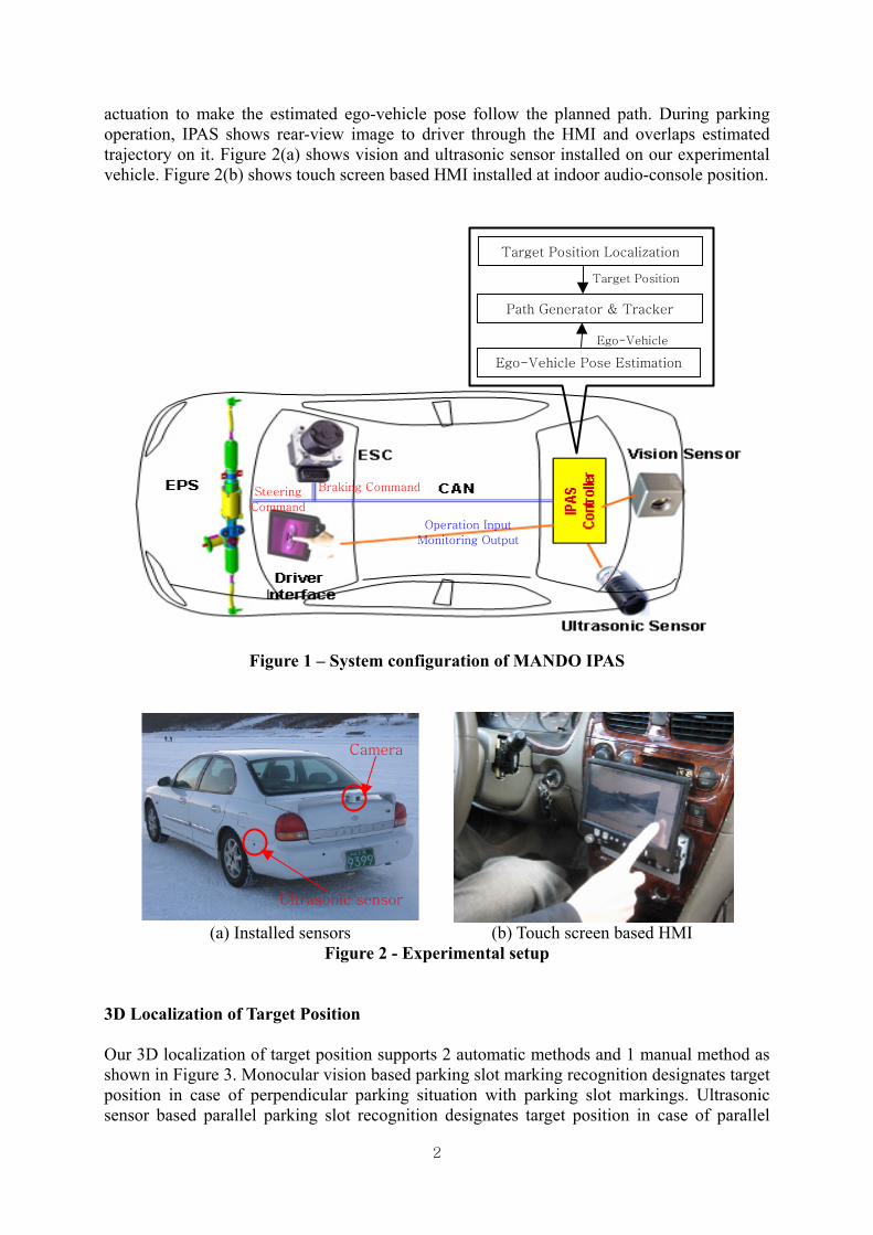
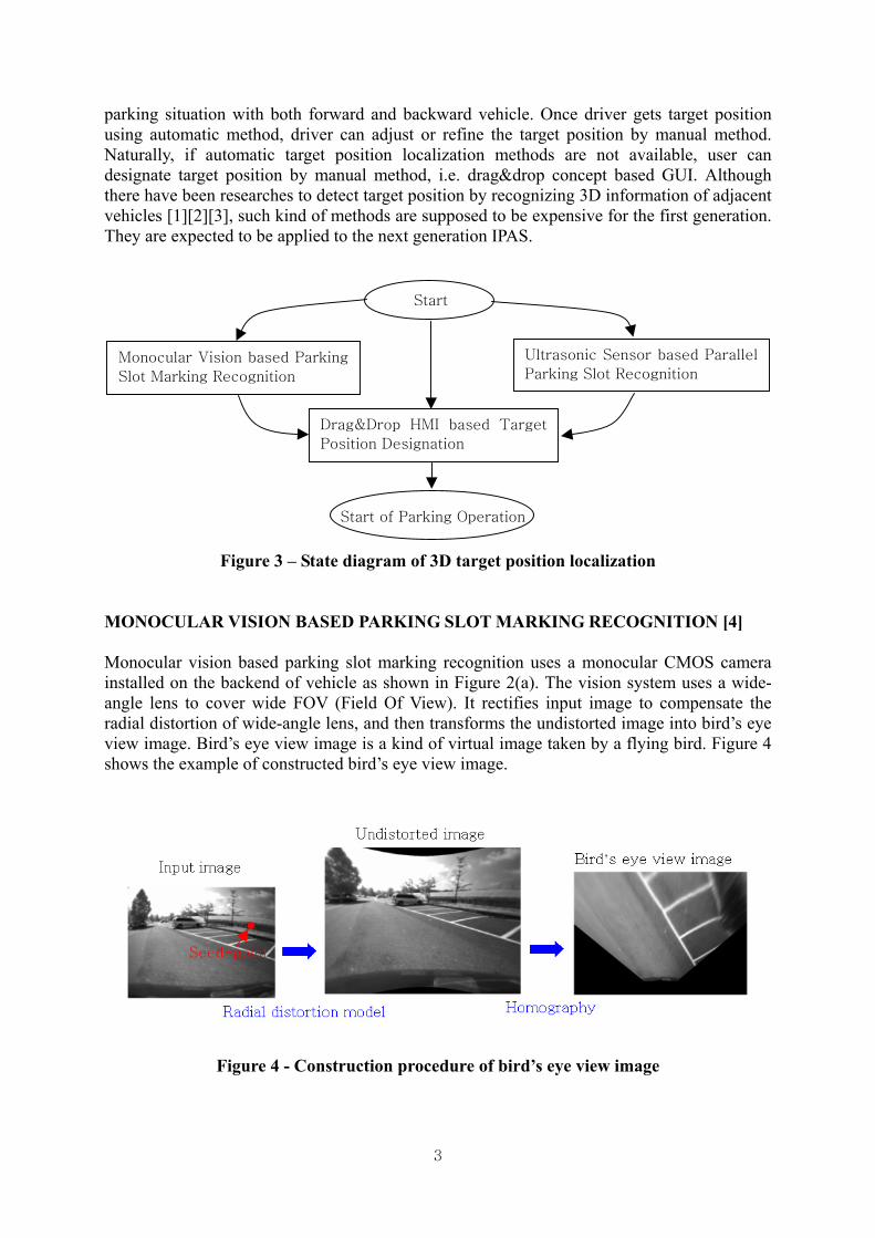
actuation to make the estimated ego-vehicle pose follow the planned path. During parking operation, IPAS shows rear-view image to driver through the HMI and overlaps estimated trajectory on it. Figure 2(a) shows vision and ultrasonic sensor installed on our experimental vehicle. Figure 2(b) shows touch screen based HMI installed at indoor audio-console position.
Target Position Localization
Target Position
Ego-Vehicle
Ego-Vehicle Pose Estimation
Path Generator & Tracker
Operation Input
Monitoring Output
Braking CommandSteering
Command
Figure 1 – System configuration of MANDO IPAS
Camera
Ultrasonic sensor
(a) Installed sensors (b) Touch screen based HMI Figure 2 - Experimental setup
3D Localization of Target Position Our 3D localization of target position supports 2 automatic methods and 1 manual method as shown in Figure 3. Monocular vision based parking slot marking recognition designates target position in case of perpendicular parking situation with parking slot markings. Ultrasonic sensor based parallel parking slot recognition designates target position in case of parallel
2
parking situation with both forward and backward vehicle. Once driver gets target position using automatic method, driver can adjust or refine the target position by manual method. Naturally, if automatic target position localization methods are not available, user can designate target position by manual method, i.e. drag&drop concept based GUI. Although there have been researches to detect target position by recognizing 3D information of adjacent vehicles [1][2][3], such kind of methods are supposed to be expensive for the first generation. They are expected to be applied to the next generation IPAS.
Start
Monocular Vision based Parking
Slot Marking Recognition
Ultrasonic Sensor based Parallel
Parking Slot Recognition
Drag&Drop HMI based Target
Position Designation
Start of Parking Operation
Figure 3 – State diagram of 3D target position localization MONOCULAR VISION BASED PARKING SLOT MARKING RECOGNITION [4] Monocular vision based parking slot marking recognition uses a monocular CMOS camera installed on the backend of vehicle as shown in Figure 2(a). The vision system uses a wide-angle lens to cover wide FOV (Field Of View). It rectifies input image to compensate the radial distortion of wide-angle lens, and then transforms the undistorted image into bird’s eye view image. Bird’s eye view image is a kind of virtual image taken by a flying bird. Figure 4 shows the example of constructed bird’s eye view image.
Seed-point
Figure 4 - Construction procedure of bird’s eye view image
3

Vision system starts recognition procedure from the seed point, which is designated by driver with touch screen. Figure 5(a) shows a line from the seed point to camera position in bird’s eye view image. Figure 5(b) is the intensity profile along the line and Figure 5(c) is the directional intensity gradient along the line. Detecting positive peaks recognizes marking line-segments as shown in Figure 5(c). Figure 5(d) shows recognized marking line-segments. Edge following can reject false marking line-segments and refine the direction of line-segment as show in Figure 5(e). Among the refined line-segments, the line-segment nearest to the camera is recognized as guideline, which is the border between roadway and parking slots. Once guideline is recognized, the projection of seed point to the guideline becomes reference point. By investigating the intensity ratio between on-marking intensity and off-marking intensity, ‘T’-shape junction can be easily detected as shown in Figure 5(g). Consequently, designated parking slot can be recognized as shown in Figure 5(f). Proposed method works well in spite of adjacent vehicles thanks to the fact that it uses only guideline and ‘T’-shape junctions.
(a) Reference line (b) Intensity profile (c) Directional gradient
(d) Recognized lines (e) Edge following result (f) Recognized guideline
(g) Separating line recognition by intensity ratio (f) Recognized parking slot
Figure 5 – Parking slot recognition procedure
4

ULTRASONIC SENSOR BASED PARALLEL PARKING SLOT RECOGNITION [5] In parallel parking situation, primarily interesting obstacles, i.e. parked vehicles, can be out of camera coverage. Distance measurements, collected during parallel parking preparation driving by ultrasonic sensor, can designate free parking slot. Figure 6(a) shows the collected range data and clustering result. O1 and O2 are object clusters and F1 and F2 are free-space clusters. After the clustering, two end positions of the nearest free-space cluster are extracted: in Figure 6(b), p1 and p2. Adjacent end points of neighboring object clusters, i.e. c1 and c2, provide the outer border of free space, l. Vehicle pose estimator eliminates the effect of relative position with respect to adjacent vehicles. Figure 6(c) shows detected free space, from range data compensated with estimated ego-pose. Figure 6(d) shows the recognized free space in rear-view image.
(a) Distance clustering result (b) Corner detection result
X
Y
X
Y
1O2O
1F2F
Searching direction
Detected free space
Occupied with other vehicle
Vehicle trajectory
(c) Detected free space (d) Detection result
Figure 6 – Distance clustering and corner detection DRAG&DROP HMI BASED TARGET POSITION DESIGNATION [6] Captured scene of parking site is displayed on small touch screen monitor and current target position is displayed. The inside region of rectangular target position is used as a moving cursor. The outside region of rectangular target position is used as a rotating cursor. User can easily designate the target position by the moving and rotating cursor as shown in Figure 7. Manual target designation method has two usages. First, it can refine the target position acquired by automatic target localization methods. Second, it can be used at anytime driver want to manually designate target position without automatic methods.
5

Because manual method is supposed to be inevitable in spite of the development of automatic methods, research focus should be on the improvement of efficiency and convenience. To verify the efficiency of the proposed manual method, we measure the operation time and clicking number, and then compare drag&drop based method with multiple-arrow based method. For garage parking, it is observed that operation time is reduced by 17.6% and clicking number is reduced by 64.2%. For parallel parking, it is observed that operation time is reduced by 29.4% and clicking number is reduced by 75.1% [6].
(a) Moving by dragging the inside of rectangle
(b) Rotating by dragging the outside of rectangle
Figure 7 - Target position rectangle as moving and rotating cursor
PATH PLANNING AND TRACKING After the localization of target position, parking controller generates parking path for semi-automatic guidance. Planned path of garage parking situation basically consists of two lines: line extending current vehicle’s rear direction, line extending the central line of target position. A circular segment whose radius is the smallest rotating radius of installed steering system connects the transition part of two lines as depicted by Figure 8(a). Current semi-automatic parking assist system does not consider the multi-turn parking trial situation yet. System checks whether it can track the planned path before the start of parking operation. If the path generation is successful, it is converted from Cartesian coordination to vehicle travel – steering angle space for steering control. Pose estimation uses popular Ackerman (or bicycle) model, assuming that no slip of wheels occurs due to low speed. The reference point of the vehicle motion is assumed to be located at the centre of rear axle. When the system guides vehicle to park, the operation mode of R-EPS changes from normal ‘power assist’ mode to ‘active steering control’ mode. During vehicle progresses to the target position,
6

steering angle is controlled by the R-EPS. Parking controller receives vehicle travel pulse from transmission and steering angle from R-EPS. The steering angle command at the moment is determined by referring to the vehicle travel – steering angle profile. With a serial link such as CAN channel, parking controller sends steering command to R-EPS controller, which performs angular position control. Although longitudinal control of vehicle is driver’s responsibility, visual and acoustic guidance informs the driver of over-speed warning and the completion of parking operation. Hard limitation of vehicle speed can be imposed by ESP active braking control. During parking operation, vehicle trajectory predicted by current steering angle is projected onto rear-view image to inform driver of ongoing parking situation.
(a) Path planning method (b) Predicted trajectory on rear-view image
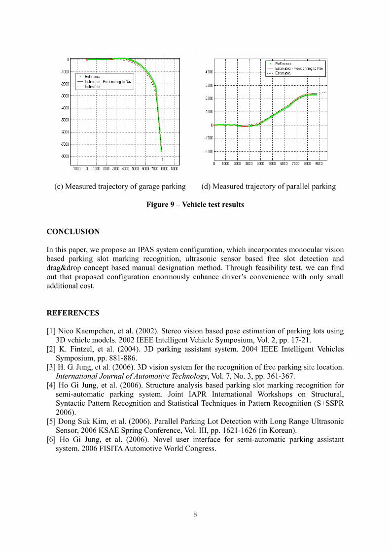
Figure 8 – Path planning and tracking EXPERIMENTAL RESULT To validate the feasibility of proposed system configuration, we conducted various kinds of vehicle tests. Figure 9(a) image sequence shows the successful garage parking operation and Figure 9(b) image sequence shows the successful parallel parking operation. Figure 9(c) and (d) shows that measured trajectories are almost the same with estimated path in case of garage parking situation and parallel parking situation respectively. Reference means measured trajectory and estimated means the trajectory by estimated vehicle pose.
(a) Garage parking example (b) Parallel parking example
7
(c) Measured trajectory of garage parking (d) Measured trajectory of parallel parking
Figure 9 – Vehicle test results CONCLUSION In this paper, we propose an IPAS system configuration, which incorporates monocular vision based parking slot marking recognition, ultrasonic sensor based free slot detection and drag&drop concept based manual designation method. Through feasibility test, we can find out that proposed configuration enormously enhance driver’s convenience with only small additional cost. REFERENCES [1] Nico Kaempchen, et al. (2002). Stereo vision based pose estimation of parking lots using
3D vehicle models. 2002 IEEE Intelligent Vehicle Symposium, Vol. 2, pp. 17-21. [2] K. Fintzel, et al. (2004). 3D parking assistant system. 2004 IEEE Intelligent Vehicles
Symposium, pp. 881-886. [3] H. G. Jung, et al. (2006). 3D vision system for the recognition of free parking site location.
International Journal of Automotive Technology, Vol. 7, No. 3, pp. 361-367. [4] Ho Gi Jung, et al. (2006). Structure analysis based parking slot marking recognition for
semi-automatic parking system. Joint IAPR International Workshops on Structural, Syntactic Pattern Recognition and Statistical Techniques in Pattern Recognition (S+SSPR 2006).
[5] Dong Suk Kim, et al. (2006). Parallel Parking Lot Detection with Long Range Ultrasonic Sensor, 2006 KSAE Spring Conference, Vol. III, pp. 1621-1626 (in Korean).
[6] Ho Gi Jung, et al. (2006). Novel user interface for semi-automatic parking assistant system. 2006 FISITA Automotive World Congress.
8