system description rockfon system t15 a/erwiumbraco-rfn.inforce.dk/media/2527346/system...
TRANSCRIPT
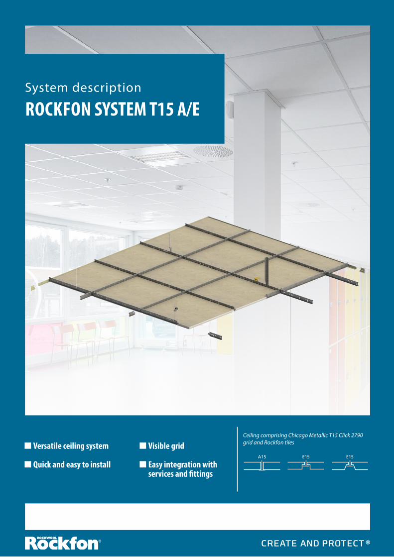
System description
ROCKFON SYSTEM T15 A/E
Versatile ceiling system
Quick and easy to install
Visible grid
Easy integration with services and fittings
E15 E15A15
Ceiling comprising Chicago Metallic T15 Click 2790 grid and Rockfon tiles

ROCKFON SYSTEM T15 A/E ROCKFON SYSTEM T15 A/E
2
Rockfon tiles in the following sizes, with A15 and E15 edge details are suitable for installation with Rockfon System T15 A/E:600 x 6001200 x 600
Rockfon System T15 A/E is a ceiling comprising a 15mm wide exposed grid made from galvanised steel with a smooth white* visible surface and square (A edge) and / or rebated, tegular (E edge) tiles. It comprises main runners, cross tees, perimeter trims and a variety of accessories. All the grid profiles have a uniform height of 38mm ensuring smoother integration of services and fittings.
Systems are also available in an Enhanced Corrosion Resistant (ECR) format for use in harsh environments.
Rockfon System T15 A/E can be either suspended or directly fastened to the soffit usinga variety of hangers.
* Other colours are available to order.
For general installation guidance, refer to the Rockfon Installation Guide for:Chicago Metallic T15 Click 2890Chicago Metallic T15 Click 2790
DESCRIPTION
Cross tees have an audible "click" to confirm they are in place, making installation and demounting quick and easy.
Full height on all profiles to provide easier integration opportunities with fittings.
A15
E15
E15
This system can create exposed and semi-concealed ceilings in 15mm width using A and E edge tiles.
6 3
21
745
1200mm
max.1200mmmax. 450mm
1200mm

ROCKFON SYSTEM T15 A/E
3
SYSTEM COMPONENTS AND CONSUMPTION GUIDE
MAIN RUNNER AND CROSS TEES
PERIMETER TRIMS
ACCESSORIES
QUANTITY/M2 1 2 3 4 5 6 7*Main runners and suspension hangerspositioned at 1200mm centres
Main runner
T15 3000
Cross teeT15 600
Cross teeT15 1200
W Shadow moulding wall
angle(L: 3050mm)
Perimeter angle trim
(L: 3050mm)
Suspension hanger
Direct suspension
clip
MODULE SIZE (mm)
600 x 600 0.84 lm 0.84 lm 1.68 lm 1) 1) 0.70 pcs 0.70 pcs1200 x 600 0.84 lm - 1.68 lm 1) 1) 0.70 pcs 0.70 pcs 1) Consumption depends on room size. *) Choose from three different depths of direct suspension clips - 50, 80 and 100mm. Max. load capacity is 45 Kg/pc when used with pin ref:165421.
1. MAIN RUNNER T15 3000
4. W SHADOW MOULDING WALL ANGLE (L: 3050mm)
6. SUSPENSION HANGER
3. CROSS TEE T15 1200
7. DIRECT SUSPENSION CLIP(Three depths available)
2. CROSS TEE T15 600
5. PERIMETER WALL ANGLE TRIM (L: 3050mm)
Use with pin 165421

ROCKFON SYSTEM T15 A/E ROCKFON SYSTEM T15 A/E
4
Code Component descriptionHeight (mm)
Length (mm) Colour
169487 Main runner T15 Click/Hook 38 3000 White 001 20 Slots 75 150 18 x 150 75
169488 Cross tee T15 Click 38 600 White 001 1 Slot 300 300
169490 Cross tee T15 Click 38 1200 White 001 3 Slots 300 300 300 300
Components available in special lengths and slottings on request.
POSITION OF SLOTS AND SUSPENSION HOLES
170595
Perimeter wall angle trim
Main runner and cross tees
170658
W Shadow moulding wall angle
CROSS SECTIONS
ROCKFON SYSTEM T15 A/E
5
1
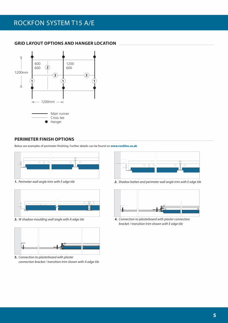
Main runnerCross teeHanger
1200600
1
3 3
600600
1200mm
1200mm
1
2
GRID LAYOUT OPTIONS AND HANGER LOCATION
Below are examples of perimeter finishing. Further details can be found on www.rockfon.co.uk
3. W shadow moulding wall angle with A edge tile
2. Shadow batten and perimeter wall angle trim with E edge tile
4. Connection to plasterboard with plaster connection bracket / transition trim shown with E edge tile
5. Connection to plasterboard with plaster connection bracket / transition trim shown with A edge tile
1. Perimeter wall angle trim with E edge tile
PERIMETER FINISH OPTIONS

ROCKFON SYSTEM T15 A/E ROCKFON SYSTEM T15 A/E
6
Tile thickness (mm) Module size (mm) D (mm)
15 - 20 600 x 6001200 x 600
100
40 - 100 600 x 6001200 x 600
200
The system loading capacity is determined based on a maximum deflection of each component equal to 1/500 of the span or the cumulative deflection of all the structural components which do not exceed 4mm. The loading capacity is shown as evenly distributed load in kg/m2. Grid weight is inclusive; tile weight is not included.
MINIMUM INSTALLATION DEPTH (mm)
SYSTEM LOADING CAPACITY
For further information, visit our online CAD library at www.rockfon.co.uk
Generate specifications for our products from the website. Explore an extensive library of reference projects at www.rockfon.co.uk
D = Minimum installation depth for easy tile installation and demountability. Depth when using direct hangers is minimum 50mm.
Kg/m²
Hanger distance (mm) Module size (mm)
Maximum deflection
2.5mm 3.3mm 4.0mm
1200 600 x 600 8.1 11.0 13.5
1200 600 x 1200 8.9 11.9 14.7
D

ROCKFON SYSTEM T15 A/E
7
Junction between ceiling and wall orother vertical surfaceThe perimeter trim should be fastened to verticalsurfaces at the required level using appropriate fixings at nominal 450mm centres. Ensure that butt joints between adjoining lengths of trim are neat and that the trim is free from kinks and remains true and level. For the best aesthetics, use as long a length of trim as possible. The minimum recommended cut length is 300mm. Timber trims, timber shadow battens and metal shadow mouldings should not be used with fire resisting/protecting ceilings.
Junction between ceiling and curvedvertical surfaceThe use of a preformed curved perimeter trimis the most appropriate method. This should beinstalled as described above. Rockfon canprovide details of curved perimeter trims onrequest.
CornersPerimeter trims should be neatly mitred at allcorner joints. Overlap mitres are acceptableon metal trims on internal corner joints unlessspecified otherwise.
PERIMETER FINISHING
ROCKFON tiles have a matt white or coloured surface and are directional. To ensure a consistent appearance to the finished ceiling, it is important that all tiles are installed in one direction, indicated by the arrow printed on the back of the tile.
Tile installationWhen installing the tiles, the use of gloves isrecommended. Rockfon tiles are easy to cut byusing a sharp knife. Apply Rockfon edge paintto any visible cut edges.
Unless specified otherwise, the ceiling shouldbe set out symmetrically and where possible,perimeter tiles should be greater than 200mmin width.
The hangers should be fastened with appropriate top fixings and to the main runners at 1200mm centres. Main runners should be positioned at 1200mm centres and levelled at the appropriate ceiling height. Main runner joints should be staggered and there should be a hanger positioned within 150mm of the fire expansion point and within 450mm of the end of the main runner where it terminates at a perimeter. Additional hangers may be necessary to support the weight of ceiling services.
When using direct hangers, a fixing pin shouldbe used to lock the hanger on to the bulb of themain runner.
1200mm x 600mm moduleFit 1200mm cross tees between the main runners at 600mm centres.
600mm x 600mm moduleAs 1200mm x 600mm module but intersect1200mm cross tees with 600mm cross tees at1200mm centres parallel to the main runner.
MAIN GRID
TILE INSTALLATION
For general installation guidance, refer to the Rockfon Installation Guide for:Chicago Metallic T15 Click 2890Chicago Metallic T15 Click 2790
ROCKFON SYSTEM T15 A/E ROCKFON SYSTEM T15 A/E
8
ENHANCED CORROSION RESISTANCE (ECR)
FIRE RESISTING / PROTECTING CEILINGS
This grid provides excellent longevity and complies with the requirements of Class B BS EN 13964.
Chicago Metallic grids are also available in an Enhanced Corrosion Resistant (ECR) format for use in harsh environments such as swimming pools.
Our ECR grids comply with the requirements of Class D BS EN 13964.
This system can be used in conjunction with many ROCKFON ceiling tiles to create a variety of specifically designed fire resisting/protecting ceiling constructions.
Many ROCKFON ceiling solutions have been tested and subsequently independently assessed in accordance with BS 476 Parts 21, 22 and 23.
For further details of the tiles, module sizes andapproved constructions, please contact ROCKFON.
Hold down clipsA variety of hold down clips suitable for usewith the many ROCKFON tiles are available for this system.
For fire resisting/ protecting ceilings, tiles should be clipped at the rate of 2 clips per 600mm edge and 3 clips per 1200mm edge.
In small rooms, entrance areas, staircases andother areas which may be subject to pressuredifferences between room and ceiling void, it isrecommended to alleviate pressure build up with the use of vents or grills. Alternatively, in some situations, clips can be used to secure the tiles into the grid system.
Hangers Wire and adjustable rod hangers should be fastened through the holes in the stalk of the main runners. Wire hangers should be passed through the hole and wrapped at least three times around itself. Adjustable rod hangers should be orientated and connected to main runners so that the lower sections of the hangers run in the same direction.
Top FixingsTop fixings are available from many specialist suppliers. It is important to be sure that the top fixings used to support the ceiling are appropriate for the specific soffit and that they provide adequate pull out strength when installed.
Service IntegrationA variety of service installations and lights can be easily integrated into this system.
Service installations should not be supported on the ceiling tile alone. Service loads should always be adequately spread on the back of the tile or transferred to the grid system using appropriate support arms or yokes. Alternatively, the service should be independently supported.
Please contact ROCKFON Technical Support for further advice.
ACCESSORIES

ROCKFONA trading division of ROCKWOOL Limited26-28 Hammersmith Grove, London, W6 7HATel: 020 8222 7457Fax: 020 8222 7458www.rockfon.co.uk
We believe our acoustic stone wool and metal solutions for ceilings and walls are a fast and simple way to create beautiful, comfortable and safe spaces.
Easy to install and durable, they protect people from noise and the spread of fire. They are our way of making a constructive contribution towards a sustainable future.
Create and Protect is what drives us. It means putting people first, sharing success and maintaining trust.
It’s our rock-solid promise to you. At ROCKFON, Create and Protect is what we do - and it’s inspired by you.
10.2014 | All colour codes m
entioned are based on the NCS - N
atural Colour System®
© property of and used on licence from
NCS Colour A
B, Stockholm 2010.
Subject to alterations in range and product technology without prior notice. RO
CKFON
accepts no responsibility for printing errors.