system design i - cnr · system design: eight issues system design 2. subsystem decomposition...
TRANSCRIPT
Usi
ng U
ML,
Pat
tern
s, an
d Ja
vaO
bjec
t-Ori
ente
d So
ftwar
e En
gine
erin
g
System Design I: System Decomposition
Bernd Bruegge & Allen H. Dutoit Object-Oriented Software Engineering: Using UML, Patterns, and Java 2
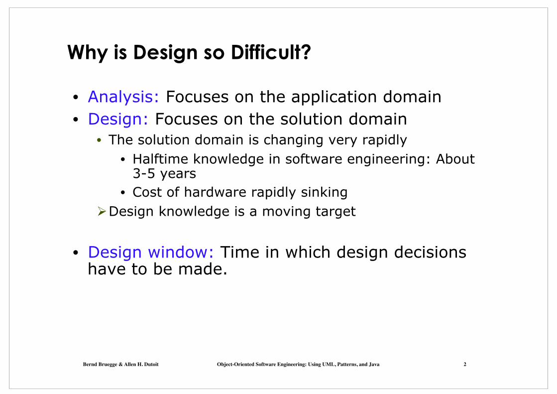
Why is Design so Difficult?
• Analysis: Focuses on the application domain • Design: Focuses on the solution domain
• The solution domain is changing very rapidly • Halftime knowledge in software engineering: About
3-5 years • Cost of hardware rapidly sinking
Ø Design knowledge is a moving target
• Design window: Time in which design decisions have to be made.

Bernd Bruegge & Allen H. Dutoit Object-Oriented Software Engineering: Using UML, Patterns, and Java 3
The Scope of System Design
• Bridge the gap • between a problem and
an existing system in a manageable way
Problem
Existing System
System Design • How?
• Use Divide & Conquer: 1) Identify design goals 2) Model the new system
design as a set of subsystems
3-8) Address the major design goals.
(new system)

Bernd Bruegge & Allen H. Dutoit Object-Oriented Software Engineering: Using UML, Patterns, and Java 4
System Design: Eight Issues System Design
2. Subsystem DecompositionLayers vs PartitionsArchitectural StyleCoherence & Coupling
4. Hardware/Software MappingIdentification of NodesSpecial Purpose SystemsBuy vs BuildNetwork Connectivity
5. Persistent DataManagement
Storing Persistent ObjectsFilesystem vs Database
Access Control ACL vs CapabilitiesSecurity
6. Global Resource Handling
8. BoundaryConditions
InitializationTerminationFailure.
3. Identify ConcurrencyIdentification of Parallelism (Processes,Threads)
7. Software Control
MonolithicEvent-DrivenConc. Processes
1. Identify Design GoalsAdditional NFRsTrade-offs
Bernd Bruegge & Allen H. Dutoit Object-Oriented Software Engineering: Using UML, Patterns, and Java 5
MonolithicEvent-DrivenConc. Processes
7. Software Control
2. System DecompositionLayers vs PartitionsCoherence/Coupling
4. Hardware/Software MappingSpecial Purpose SystemsBuy vs BuildAllocation of ResourcesConnectivity
5. DataManagement
Persistent ObjectsFilesystem vs Database
Access Control Listvs CapabilitiesSecurity
6. Global Resource Handlung
8. BoundaryConditions
InitializationTerminationFailure
3. ConcurrencyIdentification of Threads
1. Design GoalsDefinitionTrade-offs
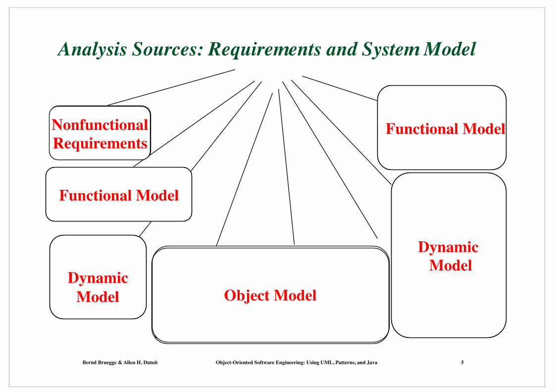
Analysis Sources: Requirements and System Model
Object Model
Functional Model
Functional Model
Dynamic Model
Dynamic Model
NonfunctionalRequirements

Bernd Bruegge & Allen H. Dutoit Object-Oriented Software Engineering: Using UML, Patterns, and Java 6
MonolithicEvent-DrivenConc. Processes
7. Software Control
2. System DecompositionLayers vs PartitionsCoherence/CouplingArchitectural Style
4. Hardware/Software MappingSpecial Purpose SystemsBuy vs BuildAllocation of ResourcesConnectivity
5. DataManagement Persistent ObjectsFilesystem vs Database
Access Control Listvs CapabilitiesSecurity
6. Global Resource Handlung
8. BoundaryConditions
InitializationTerminationFailure
3. ConcurrencyIdentification of Threads
1. Design GoalsDefinitionTrade-offs
From Analysis to System Design
Object Model
Functional Model
Functional Model
Dynamic Model
Dynamic Model
NonfunctionalRequirements
Bernd Bruegge & Allen H. Dutoit Object-Oriented Software Engineering: Using UML, Patterns, and Java 7
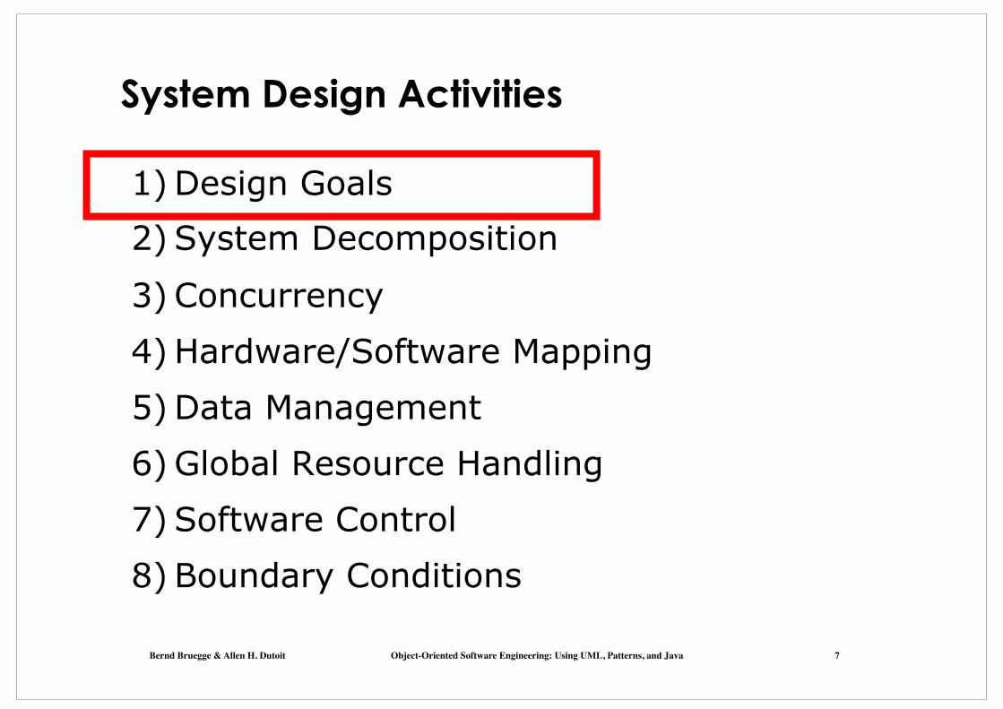
System Design Activities
1) Design Goals 2) System Decomposition
3) Concurrency 4) Hardware/Software Mapping 5) Data Management 6) Global Resource Handling 7) Software Control 8) Boundary Conditions
Bernd Bruegge & Allen H. Dutoit Object-Oriented Software Engineering: Using UML, Patterns, and Java 8
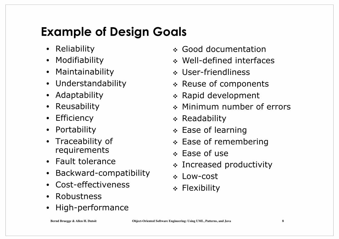
Example of Design Goals • Reliability • Modifiability • Maintainability • Understandability • Adaptability • Reusability • Efficiency • Portability • Traceability of
requirements • Fault tolerance • Backward-compatibility • Cost-effectiveness • Robustness • High-performance
❖ Good documentation ❖ Well-defined interfaces ❖ User-friendliness ❖ Reuse of components ❖ Rapid development ❖ Minimum number of errors ❖ Readability ❖ Ease of learning ❖ Ease of remembering ❖ Ease of use ❖ Increased productivity ❖ Low-cost ❖ Flexibility

Bernd Bruegge & Allen H. Dutoit Object-Oriented Software Engineering: Using UML, Patterns, and Java 9
Developer/ Maintainer
Minimum # of errors Modifiability, Readability Reusability, Adaptability Well-defined interfaces
Stakeholders have different Design Goals
Reliability
Low cost Increased productivity Backward compatibility Traceability of requirements Rapid development Flexibility
Client (Customer)
Portability Good documentation
Runtime Efficiency
End User
Functionality User-friendliness Usability Ease of learning Fault tolerant Robustness

Bernd Bruegge & Allen H. Dutoit Object-Oriented Software Engineering: Using UML, Patterns, and Java 10
Typical Design Trade-offs
• Functionality v. Usability • Cost v. Robustness • Efficiency v. Portability • Rapid development v. Functionality • Cost v. Reusability • Backward Compatibility v. Readability
Bernd Bruegge & Allen H. Dutoit Object-Oriented Software Engineering: Using UML, Patterns, and Java 11
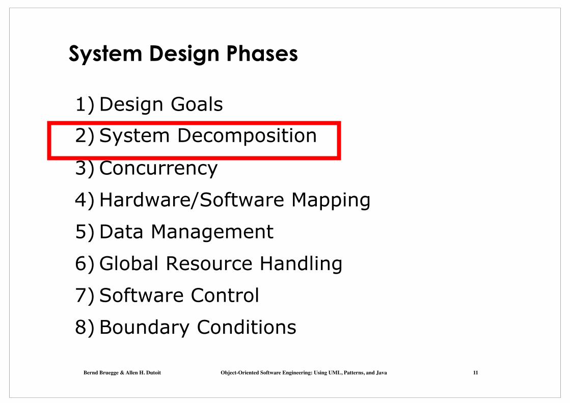
System Design Phases
1) Design Goals 2) System Decomposition
3) Concurrency 4) Hardware/Software Mapping 5) Data Management 6) Global Resource Handling 7) Software Control 8) Boundary Conditions

Bernd Bruegge & Allen H. Dutoit Object-Oriented Software Engineering: Using UML, Patterns, and Java 12
Subsystems and Services
• Subsystem • Collection of classes, associations, operations, events that
are closely interrelated with each other • The classes in the object model are the �seeds� for
subsystems • Service
• A group of externally visible operations provided by a subsystem (also called subsystem interface)
• A service is usually realized by several (public) methods exposed by the classes of the same subsystem
• The use cases in the functional model provide the �seeds� for services

Bernd Bruegge & Allen H. Dutoit Object-Oriented Software Engineering: Using UML, Patterns, and Java 13
Tournament
Component Management
User Management
Tournament Statistics
User Directory
User Interface
Session Management
Adds games, styles, and expert rating
formulas
Stores user profiles (contact info & subscriptions)
Stores results of archived
tournamentsMaintains state during matches
Administers user accounts
Advertisement
Manages tournaments,promotions,
applications
Manages advertisement banners & sponsorships
Example: Services provided by the ARENA Subsystems
Servicesare described
by subsystem interfaces

Bernd Bruegge & Allen H. Dutoit Object-Oriented Software Engineering: Using UML, Patterns, and Java 14
Subsystem Interface and API
• Subsystem interface: Set of fully typed UML operations
• Specifies the interaction and information flow from and to subsystem boundaries, but not inside the subsystem
• Refinement of service, should be well-defined and small • Subsystem interfaces are defined during object design
• Application programmer�s interface (API) • The API is the specification of the subsystem interface in
a specific programming language • APIs are defined during implementation
• The terms subsystem interface and API are often confused with each other
• The term API should not be used during system design and object design, but only during implementation.

Bernd Bruegge & Allen H. Dutoit Object-Oriented Software Engineering: Using UML, Patterns, and Java 15
Subsystems relationships
Coherence and Coupling

Bernd Bruegge & Allen H. Dutoit Object-Oriented Software Engineering: Using UML, Patterns, and Java 16
Coupling and Coherence of Subsystems
• Goal: Reduce system complexity while allowing change
• Coherence measures dependency among classes • High coherence: The classes in the subsystem perform
similar tasks and are related to each other via many associations
• Low coherence: Lots of miscellaneous and auxiliary classes, almost no associations
• Coupling measures dependency among subsystems • High coupling: Changes to one subsystem will have high
impact on the other subsystem • Low coupling: A change in one subsystem does not affect
any other subsystem.

Bernd Bruegge & Allen H. Dutoit Object-Oriented Software Engineering: Using UML, Patterns, and Java 17
Coupling and Coherence of Subsystems
• Goal: Reduce system complexity while allowing change
• Coherence measures dependency among classes • High coherence: The classes in the subsystem perform
similar tasks and are related to each other via many associations
• Low coherence: Lots of miscellaneous and auxiliary classes, almost no associations
• Coupling measures dependency among subsystems
• High coupling: Changes to one subsystem will have high impact on the other subsystem
• Low coupling: A change in one subsystem does not affect any other subsystem
Good System Design
Bernd Bruegge & Allen H. Dutoit Object-Oriented Software Engineering: Using UML, Patterns, and Java 18
Alternative
Decision
Criterion
subtasks
*
SubTask
ActionItem
DesignProblem
Task
assesses
solvableBy
resolvedBy
based-on
* * *
implementedBy
DecisionSubsystem
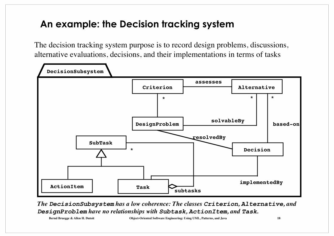
An example: the Decision tracking system
The DecisionSubsystem has a low coherence: The classes Criterion, Alternative, and DesignProblem have no relationships with Subtask, ActionItem, and Task.
The decision tracking system purpose is to record design problems, discussions, alternative evaluations, decisions, and their implementations in terms of tasks
Bernd Bruegge & Allen H. Dutoit Object-Oriented Software Engineering: Using UML, Patterns, and Java 19
Alternative
Decision
Criterion
subtasks
*
SubTask
ActionItem
DesignProblem
Task
assesses
solvableBy
resolvedBy
based-on
* * *
implementedBy
DecisionSubsystem
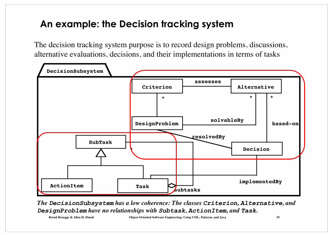
An example: the Decision tracking system
The DecisionSubsystem has a low coherence: The classes Criterion, Alternative, and DesignProblem have no relationships with Subtask, ActionItem, and Task.
The decision tracking system purpose is to record design problems, discussions, alternative evaluations, decisions, and their implementations in terms of tasks
Bernd Bruegge & Allen H. Dutoit Object-Oriented Software Engineering: Using UML, Patterns, and Java 20
subtasks
*
assesses
solvableBy
resolvedBybased-on
* * *
implementedBy
RationaleSubsystem
PlanningSubsystem
Criterion Alternative
Decision
DesignProblem
SubTask
ActionItem Task
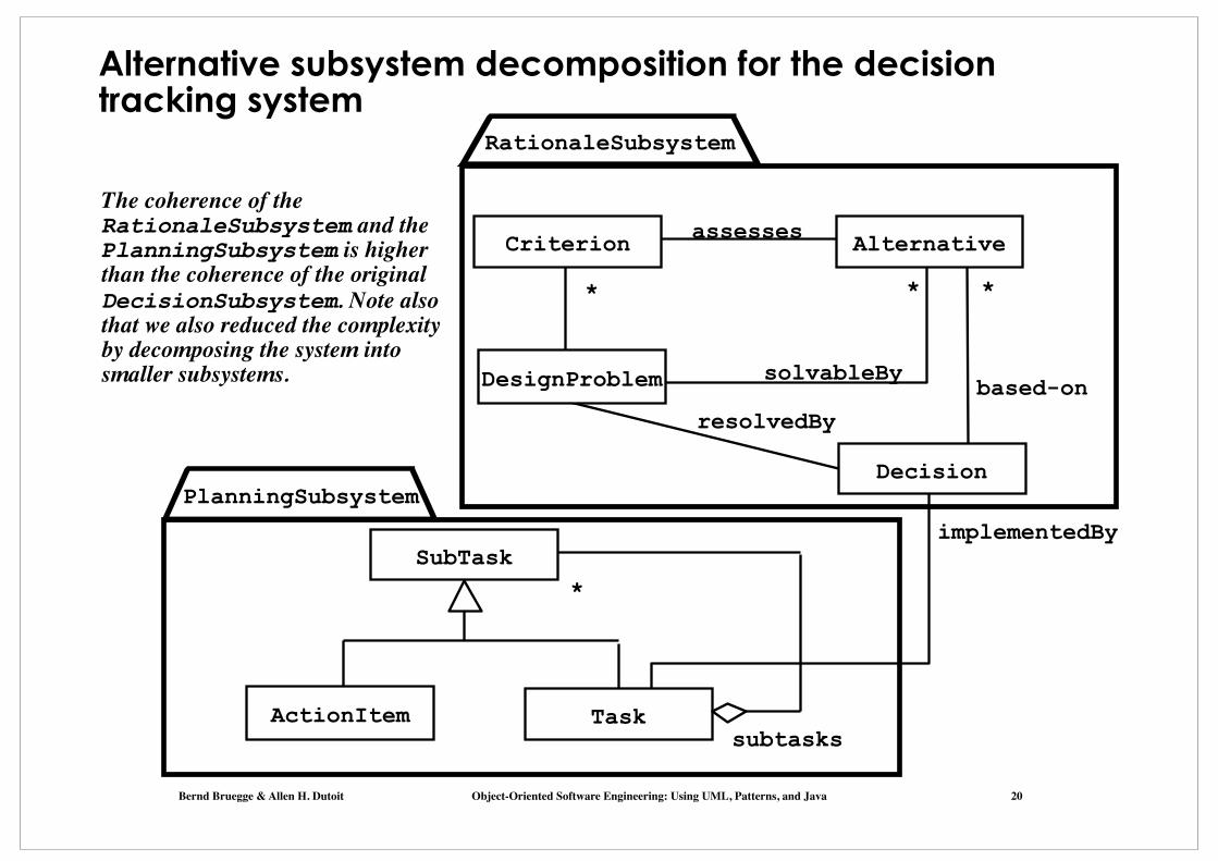
Alternative subsystem decomposition for the decision tracking system
The coherence of the RationaleSubsystem and the PlanningSubsystem is higher than the coherence of the original DecisionSubsystem. Note also that we also reduced the complexity by decomposing the system into smaller subsystems.
Bernd Bruegge & Allen H. Dutoit Object-Oriented Software Engineering: Using UML, Patterns, and Java 21
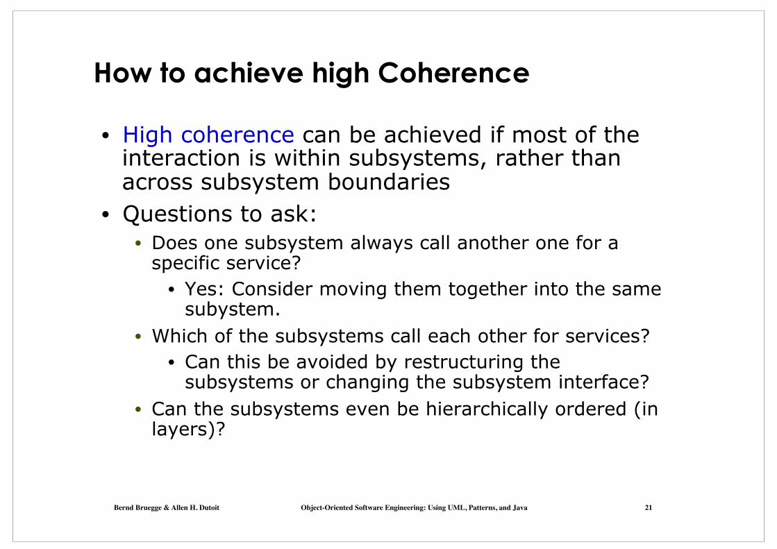
How to achieve high Coherence
• High coherence can be achieved if most of the interaction is within subsystems, rather than across subsystem boundaries
• Questions to ask: • Does one subsystem always call another one for a
specific service? • Yes: Consider moving them together into the same
subystem. • Which of the subsystems call each other for services?
• Can this be avoided by restructuring the subsystems or changing the subsystem interface?
• Can the subsystems even be hierarchically ordered (in layers)?
Bernd Bruegge & Allen H. Dutoit Object-Oriented Software Engineering: Using UML, Patterns, and Java 22
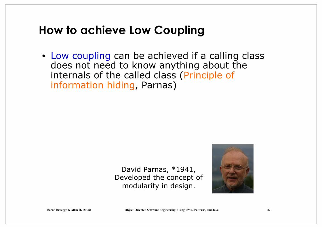
How to achieve Low Coupling
• Low coupling can be achieved if a calling class does not need to know anything about the internals of the called class (Principle of information hiding, Parnas)
David Parnas, *1941, Developed the concept of
modularity in design.

Bernd Bruegge & Allen H. Dutoit Object-Oriented Software Engineering: Using UML, Patterns, and Java 23
Is this a Good Design?
Advertisement
User Interface
Session Management
User Management
Tournament Statistics
Component Management
Tournament
No, it has too much coupling (�Spaghetti� Design)

Bernd Bruegge & Allen H. Dutoit Object-Oriented Software Engineering: Using UML, Patterns, and Java 24
Dijkstra�s answer to �Spaghetti Design�
• Dijkstra revolutionary idea in 1968 • Any system should be designed and built as a hierarchy
of layers: Each layer uses only the services offered by the lower layers
Edser W. Dijkstra, 1930-2002 Formal verification: Proofs for programs Dijkstra Algorithm, Banker�s Algorithm,
Gotos considered harmful, T.H.E., 1972 Turing Award

Bernd Bruegge & Allen H. Dutoit Object-Oriented Software Engineering: Using UML, Patterns, and Java 25
Architectural Style vs Architecture (Terms Definition) • Subsystem decomposition: Identification of
subsystems, services, and their relationship to each other
• Architectural Style: A pattern for a subsystem decomposition
• Software Architecture: Instance of an architectural style.

Bernd Bruegge & Allen H. Dutoit Object-Oriented Software Engineering: Using UML, Patterns, and Java 26
Examples of Architectural Styles
• Layered Architectural style • Service-Oriented Architecture (SOA)
• Client/Server • Peer-To-Peer • Three-tier, Four-tier Architecture • Repository • Model-View-Controller • Pipes and Filters

Bernd Bruegge & Allen H. Dutoit Object-Oriented Software Engineering: Using UML, Patterns, and Java 27
Partitions and Layers
Partitioning and layering are techniques to achieve low coupling.
A large system is usually decomposed into
subsystems using both, layers and partitions. • Partitions vertically divide a system into several
independent (or weakly-coupled) subsystems that provide services on the same level of abstraction.
• A layer is a subsystem that provides services to a higher level of abstraction
• A layer can only depend on lower layers • A layer has no knowledge of higher layers

Bernd Bruegge & Allen H. Dutoit Object-Oriented Software Engineering: Using UML, Patterns, and Java 28
The Layered Architectural Style
Client Layer N
Layer N-1
Layer N-2
Layer 1
Layer 0
.
.
.
uses
calls
calls
calls
calls
HierarchicalRelationship

Hierarchical Relationships between Subsystems
• There are two major types of hierarchical relationships • Layer A �depends on��layer B (compile time dependency)
• Example: Build dependencies (make, ant, maven) • Layer A �calls��layer B (runtime dependency)
• Example: A web browser calls a web server • Can the client and server layers run on the same machine?
• Yes, they are layers, not processor nodes • Mapping of layers to processors is decided during the Software/hardware mapping!
• UML convention: • Runtime relationships are associations with dashed lines • Compile time relationships are associations with solid
lines.

Bernd Bruegge & Allen H. Dutoit Object-Oriented Software Engineering: Using UML, Patterns, and Java 30
F:SubsystemE:Subsystem G:Subsystem
D:SubsystemC:SubsystemB:Subsystem
A:Subsystem Layer 1
Layer 2
Layer 3
Example of a System with more than one Hierarchical Relationship
Layer Relationship „depends on�
Layer Relationship
„calls�
Layer Relationship
„calls�

Bernd Bruegge & Allen H. Dutoit Object-Oriented Software Engineering: Using UML, Patterns, and Java 31
Tournament
Component Management
User Management
Tournament Statistics
User Directory
User Interface
Session Management
Advertisement
Example of a Layered Design (ARENA) Layer 1
Layer 2
Layer 3
Layer 4 ?
The relationship crosses more thanone layer
Bernd Bruegge & Allen H. Dutoit Object-Oriented Software Engineering: Using UML, Patterns, and Java 32
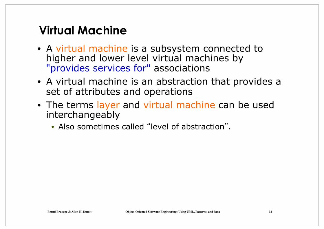
Virtual Machine • A virtual machine is a subsystem connected to
higher and lower level virtual machines by "provides services for" associations
• A virtual machine is an abstraction that provides a set of attributes and operations
• The terms layer and virtual machine can be used interchangeably
• Also sometimes called �level of abstraction�.

Building Systems as a Set of Virtual Machines A system is a hierarchy of virtual machines, each using
language primitives offered by the lower machines.
Virtual Machine 1
Virtual Machine 4 .
Virtual Machine 3
Virtual Machine 2
Existing System�
Operating System, Libraries
The language offered by Virtual Machine 1
The language offered by Virtual Machine 2

Bernd Bruegge & Allen H. Dutoit Object-Oriented Software Engineering: Using UML, Patterns, and Java 34
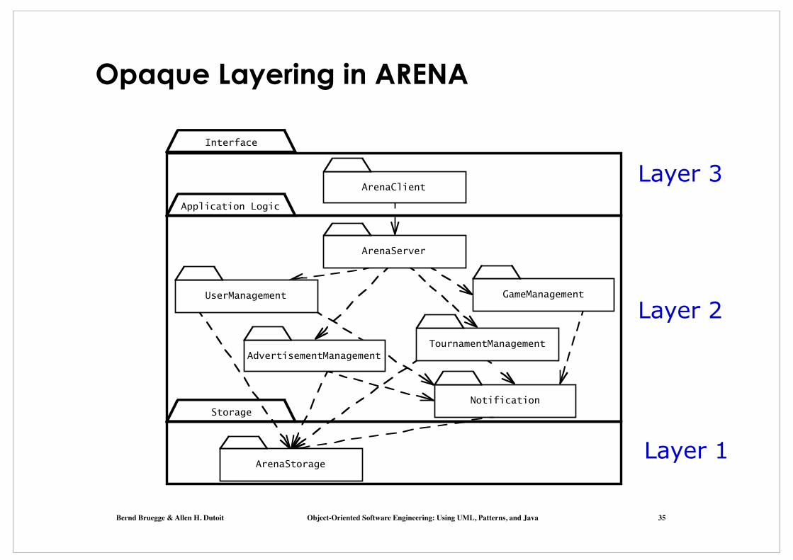
Closed Architecture (Opaque Layering)
• Each layer can only call operations from the layer below (called �direct addressing� by Buschmann et al)
L1
L2
L3
L4C1ass1attrop
C1ass3attrop
C1ass2attrop
C1assEattrop
C1assFattrop
C1assCattrop
C1assDattrop
Class Aattrop
C1ass Battrop
Design goals: Maintainability, flexibility.
Bernd Bruegge & Allen H. Dutoit Object-Oriented Software Engineering: Using UML, Patterns, and Java 35
Opaque Layering in ARENA
ArenaServer
Notification
ArenaClient
UserManagement
AdvertisementManagement
GameManagement
ArenaStorage
TournamentManagement
Interface
Storage
Application Logic
Layer 1
Layer 2
Layer 3

Bernd Bruegge & Allen H. Dutoit Object-Oriented Software Engineering: Using UML, Patterns, and Java 36
Open Architecture (Transparent Layering)
• Each layer can call operations from any layer below (�indirect addressing�)
L1
L2
L3
L4
Design goal: Runtime efficiency.
C1ass1attrop
C1ass3attrop
C1ass2attrop
C1assEattrop
C1assFattrop
C1assCattrop
C1assDattrop
Class Aattrop
C1ass Battrop

SOA is a Layered Architectural Style Service Oriented Architecture (SOA)
• Basic idea: A service provider (� business�) offers business services (�business processes�) to a service consumer (application, �customer�)
• The business services are dynamically discoverable, usually offered in web-based applications
• The business services are created by composing (choreographing) them from lower-level services (basic services)
• The basic services are usually based on legacy systems • Adapters are used to provide the �glue� between basic services and
the legacy systems.
Legacy Systems
Adapters to Legacy Systems
Basic Services
Business Services (Composite Services)
(Web-)Application
Business Services

IBM�s View of a Service Oriented Architecture
Source http://www.ibm.com/developerworks/webservices/library/ws-soa-design1/
Legacy Systems
Adapters
Basic Services
BusinessServices
User Interface(Web Portal)

Bernd Bruegge & Allen H. Dutoit Object-Oriented Software Engineering: Using UML, Patterns, and Java 39
• Layered systems are hierarchical. This is a desirable design
• Hierarchy reduces complexity
• Closed architectures are more portable • Provide very low coupling
• Open architectures are more efficient
Properties of Layered Systems

Bernd Bruegge & Allen H. Dutoit Object-Oriented Software Engineering: Using UML, Patterns, and Java 40
• Layered systems are hierarchical. This is a desirable design
• Hierarchy reduces complexity
• Closed architectures are more portable • Provide very low coupling
• Open architectures are more efficient • Layered systems often have a chicken-and egg
problem
G: Operating System
D: File System
Properties of Layered Systems
A: Symbolic Debugger Symbol Table
How do you open the symbol table when you are
debugging the File System?

Bernd Bruegge & Allen H. Dutoit Object-Oriented Software Engineering: Using UML, Patterns, and Java 41
Leve
l of ab
stra
ctio
n
Application
Presentation
Session
Transport
Network
DataLink
Physical
Another Example of a Layered Architectural Style
• ISO�s OSI Reference Model
• ISO = International Standard Organization
• OSI = Open System Interconnection
• Reference model which defines 7 layers and communication protocols between the layers

Bernd Bruegge & Allen H. Dutoit Object-Oriented Software Engineering: Using UML, Patterns, and Java 42
Examples of Architectural Styles
ü Layered Architectural Style ü Service-Oriented Architecture (SOA)
• Client/Server • Peer-to-Peer • Three-tier, Four-tier Architecture • Repository
• Blackboard • Model-View-Controller • Pipes and Filters
Bernd Bruegge & Allen H. Dutoit Object-Oriented Software Engineering: Using UML, Patterns, and Java 43
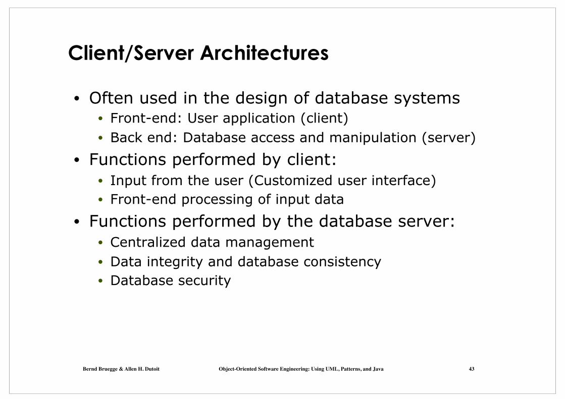
Client/Server Architectures
• Often used in the design of database systems • Front-end: User application (client) • Back end: Database access and manipulation (server)
• Functions performed by client: • Input from the user (Customized user interface) • Front-end processing of input data
• Functions performed by the database server: • Centralized data management • Data integrity and database consistency • Database security

Bernd Bruegge & Allen H. Dutoit Object-Oriented Software Engineering: Using UML, Patterns, and Java 44
Client/Server Architectural Style • Special case of the Layered Architectural style
• One or many servers provide services to instances of subsystems, called clients
Client
Server
+service1()+service2()
+serviceN()
**
requester provider
• Each client calls on the server, which performs some service and returns the result
The clients know the interface of the serverThe server does not need to know the interface of the client
• The response in general is immediate • End users interact only with the client.

Design Goals for Client/Server Architectures
Location- Transparency
Server runs on many operating systems and many networking environments
Server might itself be distributed, but provides a single "logical" service to the user Client optimized for interactive display-intensive tasks; Server optimized for CPU-intensive operations
Server can handle large # of clients
User interface of client supports a variety of end devices (PDA, Handy, laptop, wearable computer)
Service Portability
High Performance
Reliability
Scalability
Flexibility
Server should be able to survive client and communication problems.

Bernd Bruegge & Allen H. Dutoit Object-Oriented Software Engineering: Using UML, Patterns, and Java 46
Problems with Client/Server Architectures
• Client/Server systems do not provide peer-to-peer communication
• Peer-to-peer communication is often needed • Example:
• Database must process queries from application and should be able to send notifications to the application when data have changed
application1:DBUser
database:DBMS
1. updateData
application2:DBUser 2. changeNotification

Bernd Bruegge & Allen H. Dutoit Object-Oriented Software Engineering: Using UML, Patterns, and Java 47
Peer-to-Peer Architectural Style Generalization of Client/Server Architectural Style
Peer
service1()service2()
serviceN()…
requester
provider
*
*
Introduction a new abstraction: Peer “ ” How do we model this statement? With Inheritance?
�A peer can be a client as well as a server�.

Bernd Bruegge & Allen H. Dutoit Object-Oriented Software Engineering: Using UML, Patterns, and Java 48
Relationship Client/Server & Peer-to-Peer Problem statement
Which model is correct? Model 1: �A peer can be either a client or a server� Model 2: �A peer can be a client as well as a server� Peer
service1()service2()
serviceN()…
requester
provider
*
*
Client Server
✔Model 1
Model 2
NO

Bernd Bruegge & Allen H. Dutoit Object-Oriented Software Engineering: Using UML, Patterns, and Java 49
3-Layer-Architectural Style 3-Tier Architecture
Definition: 3-Layered Architectural Style • An architectural style, where an application consists of 3
hierarchically ordered subsystems • A user interface, middleware and a database system • The middleware subsystem services data requests
between the user interface and the database subsystem
Definition: 3-Tier Architecture • A software architecture where the 3 layers are allocated
on 3 separate hardware nodes
• Note: Layer is a type (e.g. class, subsystem) and Tier is an instance (e.g. object, hardware node)
• Layer and Tier are often used interchangeably.
Bernd Bruegge & Allen H. Dutoit Object-Oriented Software Engineering: Using UML, Patterns, and Java 50
Example of a 3-Layered Architectural Style
• Three-Layered Architectural style are often used for the development of Websites: 1. The Web Browser implements the user interface 2. The Web Server serves requests from the web
browser 3. The Database manages and provides access to the
persistent data.
Bernd Bruegge & Allen H. Dutoit Object-Oriented Software Engineering: Using UML, Patterns, and Java 51
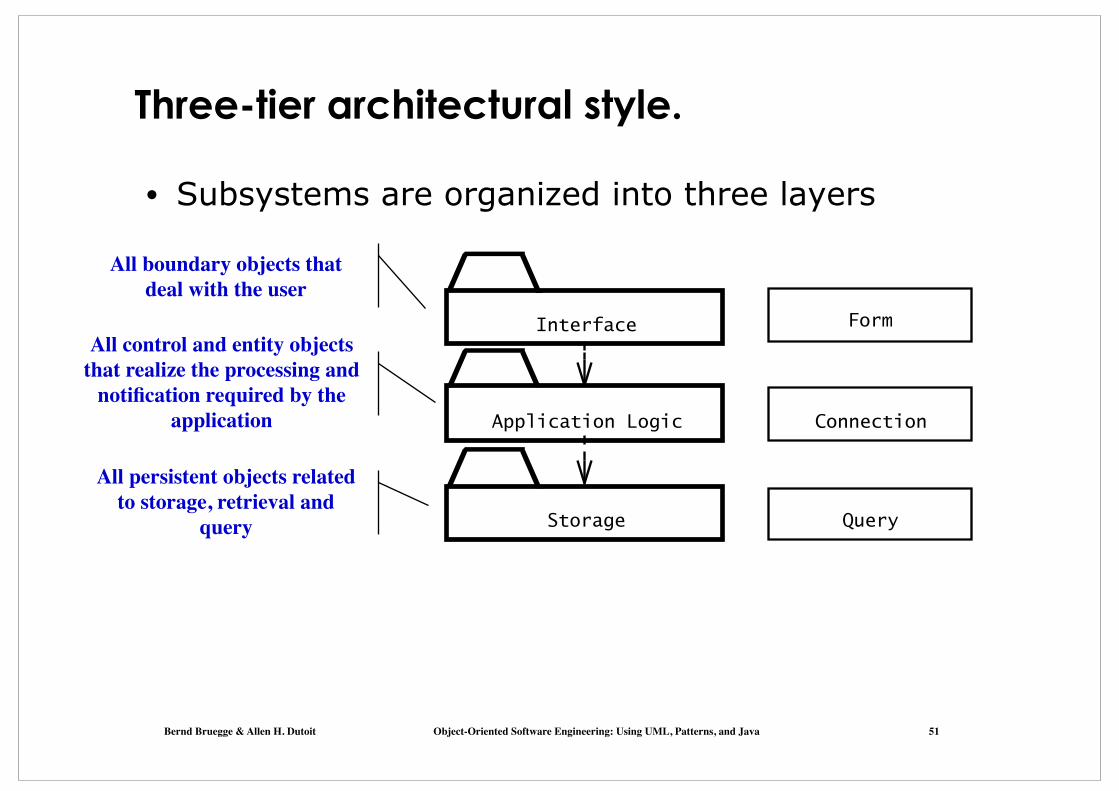
Three-tier architectural style.
Interface
Application Logic
Storage
Connection
Form
Query
• Subsystems are organized into three layers
All boundary objects that deal with the user
All control and entity objects that realize the processing and
notification required by the application
All persistent objects related to storage, retrieval and
query

Bernd Bruegge & Allen H. Dutoit Object-Oriented Software Engineering: Using UML, Patterns, and Java 52
Example of a 4-Layered Architectural Style
4-Layer-architectural styles are usually used for the development of electronic commerce sites. The layers are 1. The Web Browser, providing the user interface 2. A Web Server, serving static HTML requests 3. An Application Server, providing session management
(for example the contents of an electronic shopping cart) and processing of dynamic HTML requests
4. A back end Database, that manages and provides access to the persistent data • In commercially available 4-tier architectures, this
is usually a relational database management system (RDBMS).

Bernd Bruegge & Allen H. Dutoit Object-Oriented Software Engineering: Using UML, Patterns, and Java 53
Four-tier architectural style.
Presentation Server
Application Logic
Storage
Connection
Form
Query
Presentation Client WebBrowser
• Subsystems are organized into four layers • Web-based applications

Repository Architectural Style
• The basic idea behind this architectural style is to support a collection of independent programs that work cooperatively on a common data structure called the repository
• Subsystems access and modify data from the repository. The subsystems are loosely coupled (they interact only through the repository).
Subsystem
Repository
createData()
setData()
getData()
searchData()
*

Bernd Bruegge & Allen H. Dutoit Object-Oriented Software Engineering: Using UML, Patterns, and Java 55
Repository Architecture Example: Incremental Development Environment (IDE)
LexicalAnalyzer
SyntacticAnalyzerSemanticAnalyzer
CodeGenerator
Compiler
Optimizer
ParseTree SymbolTable
Repository
SyntacticEditor SymbolicDebugger
Parse Tree
Symbol Table

Bernd Bruegge & Allen H. Dutoit Object-Oriented Software Engineering: Using UML, Patterns, and Java 56
Repository architectures: when and why
• Repository architectures are well suited for applications with constantly changing complex data processing tasks.
• Once a central repository is well defined, we can easily add new services in the form of additional subsystems.
• The main disadvantage of repository systems is that the central repository can quickly become a bottleneck, both from a performance aspect and a modifiability aspect.
• The coupling between each subsystem and the repository is high, thus making it difficult to change the repository without having an impact on all subsystems.

Bernd Bruegge & Allen H. Dutoit Object-Oriented Software Engineering: Using UML, Patterns, and Java 57
Model-View-Controller Architectural Style • Problem: In systems with high coupling changes
to the user interface (boundary objects) often force changes to the entity objects (data)
• The user interface cannot be reimplemented without changing the representation of the entity objects
• The entity objects cannot be reorganized without changing the user interface
• Solution: Decoupling! The model-view-controller (MVC) architectural style decouples data access (entity objects) and data presentation (boundary objects)
• Views: Subsystems containing boundary objects • Model: Subsystem with entity objects • Controller: Subsystem mediating between Views (data
presentation) and Models (data access).

Model-View-Controller Architectural Style • Subsystems are classified into 3 different types
Model subsystem: Responsible for application domain knowledge
subscribernotifier
*
1
initiatorrepository1*
View subsystem: Responsible for displaying information to the user Controller subsystem: Responsible for interacting with the user and notifying views of changes in the model
Model
Controller
View
Class Diagram

Bernd Bruegge & Allen H. Dutoit Object-Oriented Software Engineering: Using UML, Patterns, and Java 59
Example: Modeling the Sequence of Events in MVC
:Controller
:Model1.0 Subscribe
:PowerpointView
4.0 User types new filename
7.0 Show updated views
:InfoView
5.0 Request name change in model
:FolderView
6.0 Notify subscribers
UML Communication Diagram
UML Class Diagram
3.0Subscribe
2.0Subscribe
subscribernotifier
*
1
initiatorrepository1*
Model
Controller
View

Bernd Bruegge & Allen H. Dutoit Object-Oriented Software Engineering: Using UML, Patterns, and Java 60
Review: UML Communication Diagram
• A Communication Diagram visualizes the interactions between objects as a flow of messages. Messages can be events or calls to operations
• Communication diagrams describe the static struc-ture as well as the dynamic behavior of a system:
• The static structure is obtained from the UML class diagram • Communication diagrams reuse the layout of classes
and associations in the class diagram • The dynamic behavior is obtained from the dynamic model
(UML sequence diagrams and UML statechart diagrams) • Messages between objects are labeled with a number
and placed near the link the message is sent over
• Reading a communication diagram involves starting at message 1.0, and following the messages from object to object.
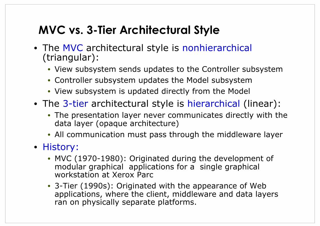
MVC vs. 3-Tier Architectural Style • The MVC architectural style is nonhierarchical
(triangular): • View subsystem sends updates to the Controller subsystem • Controller subsystem updates the Model subsystem • View subsystem is updated directly from the Model
• The 3-tier architectural style is hierarchical (linear): • The presentation layer never communicates directly with the
data layer (opaque architecture) • All communication must pass through the middleware layer
• History: • MVC (1970-1980): Originated during the development of
modular graphical applications for a single graphical workstation at Xerox Parc
• 3-Tier (1990s): Originated with the appearance of Web applications, where the client, middleware and data layers ran on physically separate platforms.

Bernd Bruegge & Allen H. Dutoit Object-Oriented Software Engineering: Using UML, Patterns, and Java 62
Pipes and Filters
• A pipeline consists of a chain of processing elements (processes, threads, etc.), arranged so that the output of one element is the input to the next element
• Usually some amount of buffering is provided between consecutive elements
• The information that flows in these pipelines is often a stream of records, bytes or bits.
Filter FilterPipeInput Output
Bernd Bruegge & Allen H. Dutoit Object-Oriented Software Engineering: Using UML, Patterns, and Java 63
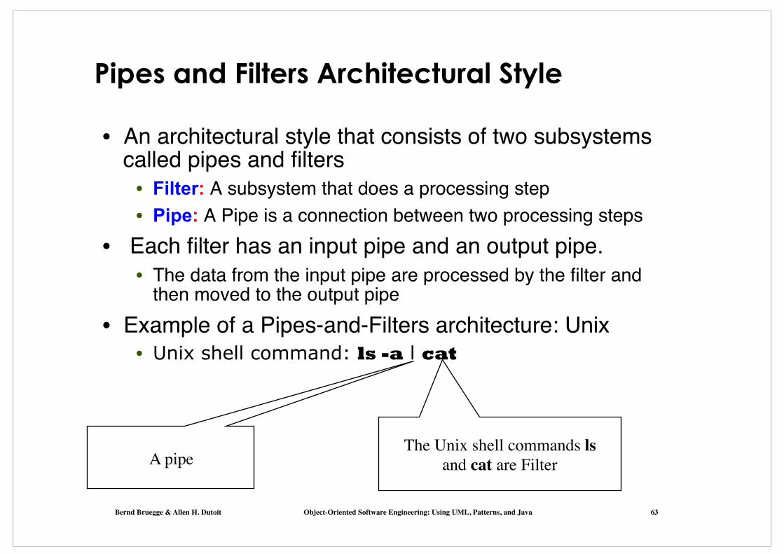
Pipes and Filters Architectural Style
• An architectural style that consists of two subsystems called pipes and filters
• Filter: A subsystem that does a processing step • Pipe: A Pipe is a connection between two processing steps
• Each filter has an input pipe and an output pipe. • The data from the input pipe are processed by the filter and
then moved to the output pipe• Example of a Pipes-and-Filters architecture: Unix
• Unix shell command: ls -a l cat
A pipeThe Unix shell commands ls
and cat are Filter
Bernd Bruegge & Allen H. Dutoit Object-Oriented Software Engineering: Using UML, Patterns, and Java 64
Summary • System Design
• Reduces the gap between problem and existing machine
• Design Goals • Describe important system qualities and values against
which alternative designs are evaluated (design-tradeoffs) • Additional nonfunctional requirements found at design time
• Subsystem Decomposition • Decomposes the overall system into manageable part by
using the principles of cohesion and coherence
• Architectural Style • A pattern for a subsystem decomposition: All kind of layer
styles (C/S, SOA, n-Tier), Repository, MVC, Pipes&Filters
• Software architecture • An instance of an architectural style.

Bernd Bruegge & Allen H. Dutoit Object-Oriented Software Engineering: Using UML, Patterns, and Java 65
Additional Readings • E.W. Dijkstra (1968)
• The structure of the T.H.E Multiprogramming system, Communications of the ACM, 18(8), pp. 453-457
• D. Parnas (1972) • On the criteria to be used in decomposing systems into
modules, CACM, 15(12), pp. 1053-1058
• J.D. Day and H. Zimmermann (1983) • The OSI Reference Model,Proc. IEEE, Vol.71, 1334-1340
• Jostein Gaarder (1991) • Sophie�s World: A Novel about the History of Philosophy
• Frank Buschmann et al: • Pattern-Oriented Software Architecture, Vol 1: A System
of Patterns, Wiley, 1996.
Bernd Bruegge & Allen H. Dutoit Object-Oriented Software Engineering: Using UML, Patterns, and Java 66
Backup Slides

Bernd Bruegge & Allen H. Dutoit Object-Oriented Software Engineering: Using UML, Patterns, and Java 67
How the Analysis Models influence System Design
• Nonfunctional Requirements => Definition of Design Goals
• Functional model => Subsystem Decomposition
• Object model => Hardware/Software Mapping, Persistent Data
Management
• Dynamic model => Identification of Concurrency, Global Resource
Handling, Software Control
• Finally: Hardware/Software Mapping => Boundary conditions
Bernd Bruegge & Allen H. Dutoit Object-Oriented Software Engineering: Using UML, Patterns, and Java 68
Overview System Design I (This Lecture)
0. Overview of System Design 1. Design Goals 2. Subsystem Decomposition, Architectural Styles
System Design II (Next Lecture) 3. Concurrency: Identification of parallelism 4. Hardware/Software Mapping:
Mapping subsystems to processors 5. Persistent Data Management: Storage for entity objects 6. Global Resource Handling & Access Control:
Who can access what?) 7. Software Control: Who is in control? 8. Boundary Conditions: Administrative use cases.

Bernd Bruegge & Allen H. Dutoit Object-Oriented Software Engineering: Using UML, Patterns, and Java 69
Excursion: Communication vs Collaboration Diagrams
• UML is a living language • Communication diagram is a new term in UML 2.0 • In UML 1.x they used to be called collaboration
diagrams • You find this term still in many books and in articles in
the web
• We use the terms synonomously

Bernd Bruegge & Allen H. Dutoit Object-Oriented Software Engineering: Using UML, Patterns, and Java 70
Communication Diagrams vs Class Diagrams vs Sequence Diagrams
• Difference between communication diagrams and class diagrams:
• Association labels, roles and multiplicities are not shown in communication diagrams. Associations between objects denote messages depicted as a labeled arrows that indicate the direction of the message, using a notation similar to that used on sequence diagrams
• Difference between communication diagrams and sequence diagrams:
• Both focus on the message flow between objects • Sequence diagrams are good at illustrating the event flow
over time. They can show temporal relationsships such as causality and temporal concurrencies
• Communication diagrams focus on the structural view of the communication between objects, not the timing issues.

Bernd Bruegge & Allen H. Dutoit Object-Oriented Software Engineering: Using UML, Patterns, and Java 71
Communication Diagram: An Example

Bernd Bruegge & Allen H. Dutoit Object-Oriented Software Engineering: Using UML, Patterns, and Java 72
Exercise (Also Possible as a Homework) • Assume the communication diagram from the previous
slide is the only information you have about a system, which is currently paper-based
• You are asked to digitize the system. Reverse engineer the system model by performing these tasks:
1. Write the problem statement • Use your application domain knowledge to describe the
functional and nonfunctional requirements 2. Identify the object model
• Draw the corresponding class diagram • Add Associations: find multiplicies and role names • Identify inheritance and aggregation associations
3. Complete the dynamic model: • Draw the corresponding sequence diagram • Identify actors, events and messages
4. Identify the functional model • Identify the actors and use cases.

Bernd Bruegge & Allen H. Dutoit Object-Oriented Software Engineering: Using UML, Patterns, and Java 73
5 System Design steps to create a layered architecture 1. Define the abstraction criterion
• Also called �the conceptual distance to the existing system (�platform�). Examples of abstraction criteria:
• The degree of customization for a specific domain • The degree of conceptual complexity
2. Determine the number of abstraction levels • Each abstraction layer corresponds to one layer of the pattern
3. Name the layers and assign tasks to each of them • The task of the highest layer is the overall system task, as perceived by the
client. The tasks of all the other layers are helper layers. (The lower layers provide the infrastructure needed by the higher layers)
4. Specify the services • Lower layers should be "slim“, while higher layers can cover a broader
spectrum of applicability. Also called the "inverted pyramid of reuse“
5. Refine the layering • Iterate over steps 1 to 4.

SOA Layers
• Layer 5: Access/Presentation layer • Application layer. Not part of SOA, but increasingly important because
technologies such as Web Services for Remote Portlets provide services at this level
• Level 4: Business process choreography layer • This layer provides compositions of services defined in layer 3. The
composition acts as a single service offered to applications • Layer 3: Services layer
• All the services offered by the business are located in this layer. A service is a discoverable software component with an externalized service description. This service description is available for searching, binding, and invocation by a SOA higher layer
• Layer 2: Enterprise components layer • Provides the functionality of the legacy systems via adapters. Responsible
for maintaining workload management, high-availability and load balancing • Layer 1: Operational systems layer
• Existing custom built or old applications that are still of business value, (called legacy systems). Examples: existing CRM and ERP applications.
Bernd Bruegge & Allen H. Dutoit Object-Oriented Software Engineering: Using UML, Patterns, and Java 75
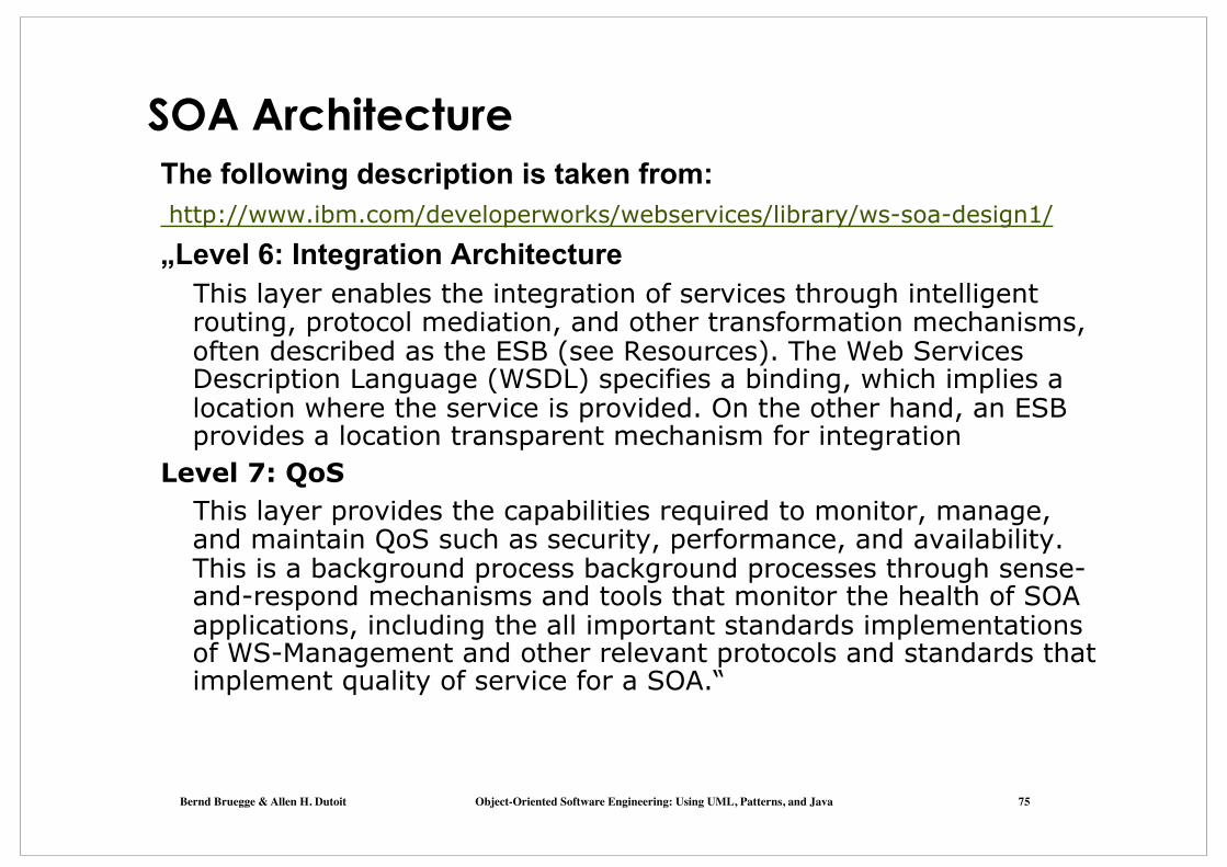
SOA Architecture The following description is taken from: http://www.ibm.com/developerworks/webservices/library/ws-soa-design1/ „Level 6: Integration Architecture
This layer enables the integration of services through intelligent routing, protocol mediation, and other transformation mechanisms, often described as the ESB (see Resources). The Web Services Description Language (WSDL) specifies a binding, which implies a location where the service is provided. On the other hand, an ESB provides a location transparent mechanism for integration
Level 7: QoS This layer provides the capabilities required to monitor, manage, and maintain QoS such as security, performance, and availability. This is a background process background processes through sense-and-respond mechanisms and tools that monitor the health of SOA applications, including the all important standards implementations of WS-Management and other relevant protocols and standards that implement quality of service for a SOA.“

Bernd Bruegge & Allen H. Dutoit Object-Oriented Software Engineering: Using UML, Patterns, and Java 76
Question to the Previous Slide
• Is Integration Architecture a good term for a layer?
• Are these layers? If yes, how should they be drawn? If not, why not?
Bernd Bruegge & Allen H. Dutoit Object-Oriented Software Engineering: Using UML, Patterns, and Java 77
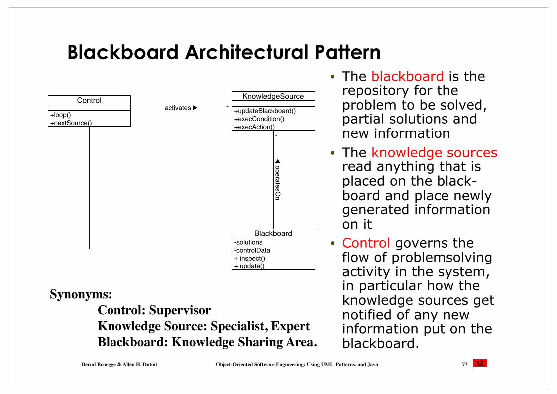
Blackboard Architectural Pattern • The blackboard is the
repository for the problem to be solved, partial solutions and new information
• The knowledge sources read anything that is placed on the black-board and place newly generated information on it
• Control governs the flow of problemsolving activity in the system, in particular how the knowledge sources get notified of any new information put on the blackboard.
+ inspect()
+ update()
-solutions
-controlData
Blackboard
+updateBlackboard()
+execCondition()
+execAction()
KnowledgeSource
+loop()
+nextSource()
Control*
*
activates !
◀ o
pera
tesO
n
Synonyms:Control: SupervisorKnowledge Source: Specialist, ExpertBlackboard: Knowledge Sharing Area.

Bernd Bruegge & Allen H. Dutoit Object-Oriented Software Engineering: Using UML, Patterns, and Java 78
Historic of Blackboard Style • The blackboard architectural styel was initially
used in the Hearsay II speech recognition system for recognizing sentences from a vocabulary of 1200 words (First called the blackboard architecture)
• In Hearsay II, hypotheses about the sentence were kept in different datastructures, so-called levels, in the blackboard (solutions in the blackboard pattern) Raj Reddy, *1937, �
Carnegie Mellon University - Major contributions in speech recognition (Hearsay II, Harpy), � vision understanding, � robotics, machine learning - Founding Director of - the Robotics Institute, - the HCI Institute, - the Center for Machine Learning1994: Turing Award (with Ed Feigenbaum).
V. Lesser, R. Fennell, L. Erman and R. Reddy (1975)
Bernd Bruegge & Allen H. Dutoit Object-Oriented Software Engineering: Using UML, Patterns, and Java 79
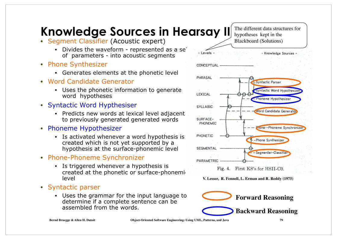
Knowledge Sources in Hearsay II • Segment Classifier (Acoustic expert)
• Divides the waveform - represented as a set of parameters - into acoustic segments
• Phone Synthesizer • Generates elements at the phonetic level
• Word Candidate Generator • Uses the phonetic information to generate
word hypotheses • Syntactic Word Hypthesiser
• Predicts new words at lexical level adjacent to previously generated generated words
• Phoneme Hypothesizer • Is activated whenever a word hypothesis is
created which is not yet supported by a hypothesis at the surface-phonemic level
• Phone-Phoneme Synchronizer • Is triggered whenever a hypothesis is
created at the phonetic or surface-phonemic level
• Syntactic parser • Uses the grammar for the input language to
determine if a complete sentence can be assembled from the words.
V. Lesser, R. Fennell, L. Erman and R. Reddy (1975)
The different data structures for hypotheses kept in the Blackboard (Solutions)
Forward Reasoning
Backward Reasoning