system design of hybrid underwater wireless optical … · · 2016-04-23wireless communication...
TRANSCRIPT

International Research Journal of Engineering and Technology (IRJET) e-ISSN: 2395 -0056
Volume: 03 Issue: 02 | Feb-2016 www.irjet.net p-ISSN: 2395-0072
© 2016, IRJET | Impact Factor value: 4.45 | ISO 9001:2008 Certified Journal | Page 514
System Design of Hybrid Underwater Wireless Optical /Acoustic Link
1Neetika, 2Satish Kumar
1-2Department of Electronics and Communication Engineering, Amity University
Lucknow, India
----------------------------------------------------------------------------------------------------------------------------------
Abstract: The recognition of underwater wireless optical
communication (UWOC) has been ever increasing for
applications of underwater exploration and
environmental oversees arrangements. UWOC technology
plays prominent role in climate recording, pollution
control and management of natural disasters, marine
biology, detection of objects, discovery of natural
resources and ocean bottom imaging and mapping.
Though acoustic modems have long been the failure of
wireless communication method for under water
applications. High speed communication has incited the
exploration of non-acoustic methods that have earlier
been overlooked due to their distance limitations. In order
to overcome these limitations, optical wireless
communication has been suggested in this paper as the
best alternative and a hybrid design is proposed using an
optical/acoustic link.
Keywords: Acoustic Transmission Loss, Extinction Coefficient, Optical Attenuation
I. INTRODUCTION
Major part of earth is covered with water (approximately 70%) therefore, it is an important segment/factor for UWOC link design. Nowadays acoustic technology is used for organizing wireless communication link between divers and ships, or transmitting long range remote signals. Acoustic technology had certain restraints like frequency attenuation characteristic which restricted to achieve high data rate. In addition it was difficult to design cost effective portable communication devices. In recent years, underwater wireless optical communications (UWOC) has engaged considerable attention as a substitute technology to traditional acoustic approach. UWOC systems manipulate the blue/green region of visible light spectrum to comprehend data transmission Due to these advantages; UWOC has numerous applications such as remote
sensing and exploration, visualizing as well as high throughput sensor network, real-time video communications. The absorption and scattering may recommend the effects of energy loss and optical beam direction also changes. High speed underwater optical communications have at least three different advantages over acoustic communications. The data rates feasible are high (1 to 10Mbps), the latency from when data is sent to when data is received is low and no acoustic noise affiliated with transmission. In data retrieval and storage applications high data rates are useful where, for one example, wireless data retrieval would make arrangement and improvement of certain systems more efficient. [1]
Figure1.1 System model of underwater optical communication link

International Research Journal of Engineering and Technology (IRJET) e-ISSN: 2395 -0056
Volume: 03 Issue: 02 | Feb-2016 www.irjet.net p-ISSN: 2395-0072
© 2016, IRJET | Impact Factor value: 4.45 | ISO 9001:2008 Certified Journal | Page 515
II. HYBRID LINK
The downlink of the duplex communication system from
the ship or base station to the Automatic Underwater
Vehicles (AUV), is a wide-angle low-bandwidth acoustic
link having an application for tracking and locating the
AUVs. In the meantime, the multiple uplinks have high-
bandwidth and highly directional optical links. [2].
Figure 2.1 Hybrid communication link environment
Optical (Uplink) Transmission:
The information from the underwater system should be collected by UUC. This information signal is modulated, amplified to increase the signal strength and transmitted to the receiver which then detects this optical signal using a photo detector. This optical signal amplified by using an optical amplifier and demodulated to obtain the electrical output. This electrical output is processed to obtain the information shown in figure 2.2
Figure 2.2 Block Diagram of Optical Uplink Transmission
Acoustic (Downlink) Transmission: A simple block diagram of the data transmission scheme includes a projector (transmitter) and a hydrophone (receiver). A hydrophone use as a microphone used for underwater recording or listening to underwater sound. Most hydrophones are depend on a piezoelectric transducer that produces electricity when subjected to a
pressure change. Such piezoelectric materials or transducers can convert a sound signal into an electrical signal since sound is a pressure wave shown in figure 2.3
Figure 2.3 Block Diagram of Acoustic Downlink Transmission
The transmitter takes the collected sensor and navigational data and formats it into packets at the Data Source. This source modulated with the carrier frequency. The modulated signal is amplified by power amplifier. Now electrical to acoustic conversion takes place to a level sufficient for signal reception at the receiver.
Acoustic Receiver:
On the receiver side, the hydrophone converts the sound pressure that hits the hydrophone to electrical energy. Now acoustic to electrical conversion take place. Then signal detection includes amplification and shaping of the input to conclude a discernible signal shown in figure 2.4. The carrier frequency is then supplied for demodulation, before the transmitted data is available for use within the vehicle for either data storage or for input into the vehicles control and exploration requirements.
Figure 2.4 Block Diagram of Acoustic Receiver
International Research Journal of Engineering and Technology (IRJET) e-ISSN: 2395 -0056
Volume: 03 Issue: 02 | Feb-2016 www.irjet.net p-ISSN: 2395-0072
© 2016, IRJET | Impact Factor value: 4.45 | ISO 9001:2008 Certified Journal | Page 516
III. HYBRID LINK ARRANGEMENT
The hybrid link arrangement has proposed two procedures for underwater wireless optical communication (UWOC). The first arrangement (Figure 3.1) employs both acoustic wave and optical wave as duplex transmission medium. In this arrangement, the two ends of the link are all mobile underwater vehicles that outfitted with both acoustic and optical transceivers. When there is short distance between nodes and water condition is clear, the system will use optical wave as carrier to achieve high speed data transmission. If there is large distance between the two nodes or the water is turbid, the system will instead utilize acoustic methods in order to achieve connectivity. The advantage of this implementation is the high rate of flexibility and reliability but high power consumption and heavy instruments due to acoustic transceivers on both ends.
Figure 3.1 Mutual Hybrid UWOC Arrangements
In the second arrangement shown in Figure 3.2, the system is designed by one static control platform and several mobile sensor nodes. Acoustic wave is used as a broadcasting method in the downlink from control platform to each sensor node to transmit control information. While optical wave is applied in the communication links between each senor node, as well as uplinks from sensor nodes to main control platform. The hybrid UWC system utilizes the advantages of each communication method. Since acoustic wave has diffusion and long propagation distance property, it can cover the area that is giving away with senor nodes. Additionally, in the downlink from control platform to sensor nodes the transmitted information is low-speed control signals, which are suitable for acoustic
communication. On the other hand, in the uplink of the system the large capacity of oceanic monitoring data is communicate through high speed UWOC links.
Figure3.2 Broadcasting Hybrid UWOC Arrangement
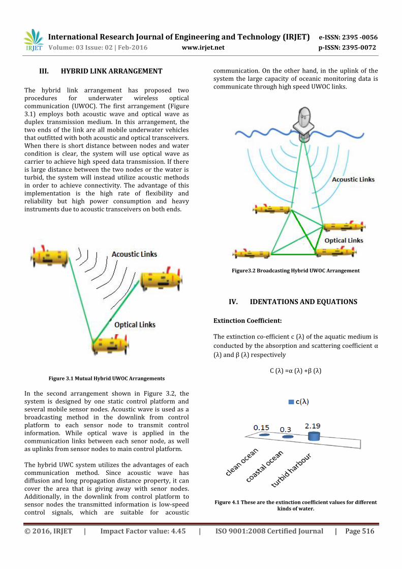
IV. IDENTATIONS AND EQUATIONS
Extinction Coefficient: The extinction co-efficient c (λ) of the aquatic medium is
conducted by the absorption and scattering coefficient α
(λ) and β (λ) respectively
C (λ) =α (λ) +β (λ)
Figure 4.1 These are the extinction coefficient values for different kinds of water.

International Research Journal of Engineering and Technology (IRJET) e-ISSN: 2395 -0056
Volume: 03 Issue: 02 | Feb-2016 www.irjet.net p-ISSN: 2395-0072
© 2016, IRJET | Impact Factor value: 4.45 | ISO 9001:2008 Certified Journal | Page 517
Figure (4.1) depicts the absorption, scattering, and extinction coefficient for three types of water–clean ocean water, coastal ocean water, and turbid harbor water. It is clear that increase in the turbidity dramatically increases the extinction coefficient from less than 0.1m-1 for pure water up to more than 2m-1 for turbid harbor water. Optical Attenuation: Optical attenuation is caused by scatter and absorption of transmitted photons. These losses are characterized by the attenuation coefficient c, which is dependent on the source wavelength. Fractional optical transmission losses O are described as [3].
λ is the transmission wavelength which is 445 nm. Attenuation is affected by optical properties of the transmission medium which for the ocean is a direct consequence of the composition. This can lead to the attenuation coefficient varying up to an order of magnitude from 0.1 m-1 in clear Open Ocean to 2.19 m-1 in turbid regions. Acoustic Transmission Loss: The acoustic transmission loss is used to calculate the Signal to Noise Ratio, where Sz (f) is the power spectral density of the transmitted signal and N (f) is the noise figure [4].
This expression means it is possible with acoustic systems to communicate beyond 1000 kilometers [5], as long as the transmission bandwidth is low and initial power high; medium length links of 100-1000 meters support up to 20–50 kHz [5]. Underwater acoustic communication channels are characterized by a path loss that depends not only on the distance between the transmitter and receiver, but also on the signal frequency. The signal frequency concludes the absorption loss which happens because of the transfer of acoustic energy into heat [6].
V. CONCLUSION
It is concluded that hybrid underwater acoustic/ optical link very helpful for communication. In hybrid underwater communication environment optical links determine the losses that occur in the system. A hybrid communication system can transmit high data rate
information by using optical transceiver. When the water turbidity is huge or the distance between the terminals is abundant, the system can be exchange to low data rate by using the acoustic transceiver. This will increase the average data rate and availability of the system.
ACKNOWLEGEMENT
I would like to thank Prof. Satish Kumar and my parents for their understanding and support. All my research paper work would not have been possible without their constant encouragement and support. My younger brother helps me in my research work.
“Special Thanks”
Respected Prof. (Dr.) O.P. Singh (Head of Department of Electronics and Communication Engineering) for his
support.
REFERENCES
[1] C. Pontbriand, N. Farr, J. Ware, J. Preisig, and H. Popenoe, “Diffuse high-bandwidth optical communications,” OCEANS 2008, pp. 1-4, Sep. 2008.
[2] Laura J. Johnson, Roger J. Green, and Mark S. Leeson, “Hybrid Underwater Optical/Acoustic Link Design” , ICTON 2014, pp. 24-27.
[3] J. W. Giles, and I. N. Bankman, “Underwater optical communications systems. Part 2: Basic design considerations.” MILCOM, 2005, pp. 1700-1705, 2005.
[4]M. Stojanovic, “Underwater acoustic communications: Design considerations on the physical layer.” WONS 2008, pp. 1-10, 2008.
[5] F. Akyildiz, D. Pompili, and T. Melodia, “Underwater acoustic sensor networks: research challenges.” Ad hoc networks, vol. 3, no. 3, 257-279, 2005.
[6] K. Saraswathi, K.A. Netravathi , Dr. S Ravishankar, “A Study on channel modeling of underwater acoustic communication”, International Journal of Research in Computer and Communication Technology, Vol 3, Issue 1, January- 2014.