system development life-cycle management (sdlcm) methodology
TRANSCRIPT
UNITED STATES NUCLEAR REGULATORY COMMISSION WASHINGTON, DC
System Development and Life-Cycle Management (SDLCM)Methodology
Handbook, Version 2.3
July 2002

SDLCM Methodology Handbook
SDLCM Methodology iii Handbook, Version 2.3
ForewordNuclear Regulatory Commission (NRC) Management Directive 2.5, “Application Systems Life-Cycle Management,” establishes the policies for applications systems life-cycle management.The System Development and Life-Cycle Management (SDLCM) Methodology implementsDirective 2.5 by providing life-cycle structure and guidance to NRC Projects.
The SDLCM Methodology comprises seven components:
1. Define Initial Project Requirements
2. Acquire Support Resources
3. Design the Solution
4. Engineer the Solution
5. Deploy the Solution
6. Service the Solution
7. Decommission the Solution
The methodology is not Itself a document or a set of documents. It is the approach to doingbusiness at NRC, and it is described by a set of documents, including but not limited to thefollowing:
� SDLCM Methodology Handbook
� SDLCM Methodology Procedures, Standards, and Forms
� SDLCM Methodology Tool Inventory
� SDLCM Methodology Overview Training

SDLCM Methodology Handbook
SDLCM Methodology v Handbook, Version 2.3
Table of Contents
1. Introduction . . . . . . . . . . . . . . . . . . . . . . . . . . . . . . . . . . . . . . . . . . . . . . . . . . . . . . . . . . . . 1
1.1 Background . . . . . . . . . . . . . . . . . . . . . . . . . . . . . . . . . . . . . . . . . . . . . . . . . . . . . . . . 1
1.2 Objectives . . . . . . . . . . . . . . . . . . . . . . . . . . . . . . . . . . . . . . . . . . . . . . . . . . . . . . . . . . 1
1.3 Scope . . . . . . . . . . . . . . . . . . . . . . . . . . . . . . . . . . . . . . . . . . . . . . . . . . . . . . . . . . . . . 1
1.4 Overview . . . . . . . . . . . . . . . . . . . . . . . . . . . . . . . . . . . . . . . . . . . . . . . . . . . . . . . . . . 1
2. Methodology Overview . . . . . . . . . . . . . . . . . . . . . . . . . . . . . . . . . . . . . . . . . . . . . . . . . . . . 3
2.1 A Structured Approach . . . . . . . . . . . . . . . . . . . . . . . . . . . . . . . . . . . . . . . . . . . . . . . . 32.1.1 Seven Components . . . . . . . . . . . . . . . . . . . . . . . . . . . . . . . . . . . . . . . . . . . . . 32.1.2 Presentation of the Components . . . . . . . . . . . . . . . . . . . . . . . . . . . . . . . . . . . 4
2.2 Principles and Assumptions . . . . . . . . . . . . . . . . . . . . . . . . . . . . . . . . . . . . . . . . . . . . 5
2.3 Activities and Products . . . . . . . . . . . . . . . . . . . . . . . . . . . . . . . . . . . . . . . . . . . . . . . . 5
2.4 Feedback and Improvement . . . . . . . . . . . . . . . . . . . . . . . . . . . . . . . . . . . . . . . . . . . . 7
2.5 Systems Concepts . . . . . . . . . . . . . . . . . . . . . . . . . . . . . . . . . . . . . . . . . . . . . . . . . . . 8
3. Selecting an Appropriate Software . . . . . . . . . . . . . . . . . . . . . . . . . . . . . . . . . . . . . . . . . . 10
3.1 Waterfall development Life-cycle Model . . . . . . . . . . . . . . . . . . . . . . . . . . . . . . . . . . 11
3.2 Incremental Development Life-cycle Model . . . . . . . . . . . . . . . . . . . . . . . . . . . . . . . 13
3.3 Evolutionary Development Life-cycle Model . . . . . . . . . . . . . . . . . . . . . . . . . . . . . . . 14
3.4 Package-based Development Life-Cycle Model . . . . . . . . . . . . . . . . . . . . . . . . . . . . 16
4. Quality Assurance . . . . . . . . . . . . . . . . . . . . . . . . . . . . . . . . . . . . . . . . . . . . . . . . . . . . . . 18
4.1 Purpose . . . . . . . . . . . . . . . . . . . . . . . . . . . . . . . . . . . . . . . . . . . . . . . . . . . . . . . . . . 18
4.2 Quality Assurance Goals . . . . . . . . . . . . . . . . . . . . . . . . . . . . . . . . . . . . . . . . . . . . . 18
4.3 Process Implementation . . . . . . . . . . . . . . . . . . . . . . . . . . . . . . . . . . . . . . . . . . . . . . 18
4.4 Measurement and Analysis . . . . . . . . . . . . . . . . . . . . . . . . . . . . . . . . . . . . . . . . . . . . 19
4.5 Verifying Implementation . . . . . . . . . . . . . . . . . . . . . . . . . . . . . . . . . . . . . . . . . . . . . 19
5. Configuration Management . . . . . . . . . . . . . . . . . . . . . . . . . . . . . . . . . . . . . . . . . . . . . . . 21
5.1 CM Process Implementation . . . . . . . . . . . . . . . . . . . . . . . . . . . . . . . . . . . . . . . . . . . 21
5.2 Configuration Identification . . . . . . . . . . . . . . . . . . . . . . . . . . . . . . . . . . . . . . . . . . . . 22
5.3 Configuration Control . . . . . . . . . . . . . . . . . . . . . . . . . . . . . . . . . . . . . . . . . . . . . . . . 235.3.1 Responsibility and Process Flow . . . . . . . . . . . . . . . . . . . . . . . . . . . . . . . . . . 235.3.2 Change Vehicles . . . . . . . . . . . . . . . . . . . . . . . . . . . . . . . . . . . . . . . . . . . . . . 245.3.3 Change Management . . . . . . . . . . . . . . . . . . . . . . . . . . . . . . . . . . . . . . . . . . 245.3.4 Release Management . . . . . . . . . . . . . . . . . . . . . . . . . . . . . . . . . . . . . . . . . . 24
5.4 Configuration Status Accounting . . . . . . . . . . . . . . . . . . . . . . . . . . . . . . . . . . . . . . . 24

SDLCM Methodology Handbook
SDLCM Methodology vi Handbook, Version 2.3
5.5 Data Management . . . . . . . . . . . . . . . . . . . . . . . . . . . . . . . . . . . . . . . . . . . . . . . . . . 25
5.6 Configuration Evaluation . . . . . . . . . . . . . . . . . . . . . . . . . . . . . . . . . . . . . . . . . . . . . . 25
6. Component 1. Define Initial Project Requirements . . . . . . . . . . . . . . . . . . . . . . . . . . . . . . 26
6.1 Purpose . . . . . . . . . . . . . . . . . . . . . . . . . . . . . . . . . . . . . . . . . . . . . . . . . . . . . . . . . . 26
6.2 Roles and Responsibilities . . . . . . . . . . . . . . . . . . . . . . . . . . . . . . . . . . . . . . . . . . . . 26
6.3 Entry Criteria . . . . . . . . . . . . . . . . . . . . . . . . . . . . . . . . . . . . . . . . . . . . . . . . . . . . . . 26
6.4 Input, Activities, and Outputs . . . . . . . . . . . . . . . . . . . . . . . . . . . . . . . . . . . . . . . . . . 27
6.5 Techniques and Tools . . . . . . . . . . . . . . . . . . . . . . . . . . . . . . . . . . . . . . . . . . . . . . . 29
6.6 Exit Criteria . . . . . . . . . . . . . . . . . . . . . . . . . . . . . . . . . . . . . . . . . . . . . . . . . . . . . . . . 29
6.7 Component 1 Activity Details . . . . . . . . . . . . . . . . . . . . . . . . . . . . . . . . . . . . . . . . . . 30
7. Component 2. Acquire Support Resources . . . . . . . . . . . . . . . . . . . . . . . . . . . . . . . . . . . 47
7.1 Purpose . . . . . . . . . . . . . . . . . . . . . . . . . . . . . . . . . . . . . . . . . . . . . . . . . . . . . . . . . . 477.1.1 Projects and Funding . . . . . . . . . . . . . . . . . . . . . . . . . . . . . . . . . . . . . . . . . . 477.1.2 Funding Approaches and Project Products . . . . . . . . . . . . . . . . . . . . . . . . . . 47
7.2 Roles and Responsibilities . . . . . . . . . . . . . . . . . . . . . . . . . . . . . . . . . . . . . . . . . . . . 48
7.3 Entry Criteria . . . . . . . . . . . . . . . . . . . . . . . . . . . . . . . . . . . . . . . . . . . . . . . . . . . . . . 48
7.4 Input, Activities, and Outputs . . . . . . . . . . . . . . . . . . . . . . . . . . . . . . . . . . . . . . . . . . 49
7.5 Techniques and Tools . . . . . . . . . . . . . . . . . . . . . . . . . . . . . . . . . . . . . . . . . . . . . . . 50
7.6 Exit Criteria . . . . . . . . . . . . . . . . . . . . . . . . . . . . . . . . . . . . . . . . . . . . . . . . . . . . . . . . 50
7.7 Component 2 Activity Details . . . . . . . . . . . . . . . . . . . . . . . . . . . . . . . . . . . . . . . . . . 50
8. Component 3. Design the Solution . . . . . . . . . . . . . . . . . . . . . . . . . . . . . . . . . . . . . . . . . . 62
8.1 Purpose . . . . . . . . . . . . . . . . . . . . . . . . . . . . . . . . . . . . . . . . . . . . . . . . . . . . . . . . . . 62
8.2 Roles and Responsibilities . . . . . . . . . . . . . . . . . . . . . . . . . . . . . . . . . . . . . . . . . . . . 62
8.3 Entry Criteria . . . . . . . . . . . . . . . . . . . . . . . . . . . . . . . . . . . . . . . . . . . . . . . . . . . . . . 63
8.4 Input, Activities and Outputs . . . . . . . . . . . . . . . . . . . . . . . . . . . . . . . . . . . . . . . . . . . 63
8.5 Techniques and Tools . . . . . . . . . . . . . . . . . . . . . . . . . . . . . . . . . . . . . . . . . . . . . . . 65
8.6 Exit Criteria . . . . . . . . . . . . . . . . . . . . . . . . . . . . . . . . . . . . . . . . . . . . . . . . . . . . . . . . 65
8.7 Component 3 Activity Details . . . . . . . . . . . . . . . . . . . . . . . . . . . . . . . . . . . . . . . . . . 65
9. Component 4. Engineer the Solution . . . . . . . . . . . . . . . . . . . . . . . . . . . . . . . . . . . . . . . . . 86
9.1 Purpose . . . . . . . . . . . . . . . . . . . . . . . . . . . . . . . . . . . . . . . . . . . . . . . . . . . . . . . . . . 86
9.2 Roles and Responsibilities . . . . . . . . . . . . . . . . . . . . . . . . . . . . . . . . . . . . . . . . . . . . 86
9.3 Entry Criteria . . . . . . . . . . . . . . . . . . . . . . . . . . . . . . . . . . . . . . . . . . . . . . . . . . . . . . 87
9.4 Input, Activities, and Outputs . . . . . . . . . . . . . . . . . . . . . . . . . . . . . . . . . . . . . . . . . . 87

SDLCM Methodology Handbook
SDLCM Methodology vii Handbook, Version 2.3
9.5 Techniques and Tools . . . . . . . . . . . . . . . . . . . . . . . . . . . . . . . . . . . . . . . . . . . . . . . 89
9.6 Exit Criteria . . . . . . . . . . . . . . . . . . . . . . . . . . . . . . . . . . . . . . . . . . . . . . . . . . . . . . . . 89
10. Component 5. Deploy the Solution . . . . . . . . . . . . . . . . . . . . . . . . . . . . . . . . . . . . . . . . 104
10.1 Purpose . . . . . . . . . . . . . . . . . . . . . . . . . . . . . . . . . . . . . . . . . . . . . . . . . . . . . . . . . 104
10.2 Roles and Responsibilities . . . . . . . . . . . . . . . . . . . . . . . . . . . . . . . . . . . . . . . . . . . 104
10.3 Entry Criteria . . . . . . . . . . . . . . . . . . . . . . . . . . . . . . . . . . . . . . . . . . . . . . . . . . . . . 105
10.4 Input, Activities, and Outputs . . . . . . . . . . . . . . . . . . . . . . . . . . . . . . . . . . . . . . . . . 105
10.5 Techniques and Tools . . . . . . . . . . . . . . . . . . . . . . . . . . . . . . . . . . . . . . . . . . . . . . 106
10.6 Exit Criteria . . . . . . . . . . . . . . . . . . . . . . . . . . . . . . . . . . . . . . . . . . . . . . . . . . . . . . . 108
11. Component 6. Service the Solution . . . . . . . . . . . . . . . . . . . . . . . . . . . . . . . . . . . . . . . . 127
11.1 Component Overview . . . . . . . . . . . . . . . . . . . . . . . . . . . . . . . . . . . . . . . . . . . . . . . 127
11.2 Change Management . . . . . . . . . . . . . . . . . . . . . . . . . . . . . . . . . . . . . . . . . . . . . . . 12911.2.1 Establish Change Management . . . . . . . . . . . . . . . . . . . . . . . . . . . . . . . . . 13111.2.2 Control System Changes . . . . . . . . . . . . . . . . . . . . . . . . . . . . . . . . . . . . . . 13211.2.3 Track and Report System Changes . . . . . . . . . . . . . . . . . . . . . . . . . . . . . . 136
11.3 Release Management . . . . . . . . . . . . . . . . . . . . . . . . . . . . . . . . . . . . . . . . . . . . . . . 13911.3.1 Plan Release . . . . . . . . . . . . . . . . . . . . . . . . . . . . . . . . . . . . . . . . . . . . . . . . 13911.3.2 Coordinate Release Changes . . . . . . . . . . . . . . . . . . . . . . . . . . . . . . . . . . . 14111.3.3 Track Release Changes . . . . . . . . . . . . . . . . . . . . . . . . . . . . . . . . . . . . . . . 14411.3.4 Track Releases . . . . . . . . . . . . . . . . . . . . . . . . . . . . . . . . . . . . . . . . . . . . . . 146
11.4 Release-Based Maintenance . . . . . . . . . . . . . . . . . . . . . . . . . . . . . . . . . . . . . . . . . 148
11.5 Emergency Maintenance . . . . . . . . . . . . . . . . . . . . . . . . . . . . . . . . . . . . . . . . . . . . 157
12. Component 7. Decommission the Solution . . . . . . . . . . . . . . . . . . . . . . . . . . . . . . . . . . 164
12.1 Purpose . . . . . . . . . . . . . . . . . . . . . . . . . . . . . . . . . . . . . . . . . . . . . . . . . . . . . . . . . 164
12.2 Roles and Responsibilities . . . . . . . . . . . . . . . . . . . . . . . . . . . . . . . . . . . . . . . . . . . 164
12.3 Entry Criteria . . . . . . . . . . . . . . . . . . . . . . . . . . . . . . . . . . . . . . . . . . . . . . . . . . . . . 164
12.4 Input, Activities, and Outputs . . . . . . . . . . . . . . . . . . . . . . . . . . . . . . . . . . . . . . . . . 165
12.5 Techniques and Tools . . . . . . . . . . . . . . . . . . . . . . . . . . . . . . . . . . . . . . . . . . . . . . 165
12.6 Exit Criteria . . . . . . . . . . . . . . . . . . . . . . . . . . . . . . . . . . . . . . . . . . . . . . . . . . . . . . . 167
12.7 Component 7 Activity Details . . . . . . . . . . . . . . . . . . . . . . . . . . . . . . . . . . . . . . . . . 167
Appendix A. Maintaining the SDLCM Methodology . . . . . . . . . . . . . . . . . . . . . . . . . . . . . . . 176
Appendix B. Roles and Responsibilities . . . . . . . . . . . . . . . . . . . . . . . . . . . . . . . . . . . . . . . . 177
Appendix C. Products of Projects . . . . . . . . . . . . . . . . . . . . . . . . . . . . . . . . . . . . . . . . . . . . . 183
C.1 Products of Projects by SDLCM Methodology Component . . . . . . . . . . . . . . . . . . . 183

SDLCM Methodology Handbook
SDLCM Methodology viii Handbook, Version 2.3
Appendix D. Activity Summary . . . . . . . . . . . . . . . . . . . . . . . . . . . . . . . . . . . . . . . . . . . . . . . 201
D.1 Component Review . . . . . . . . . . . . . . . . . . . . . . . . . . . . . . . . . . . . . . . . . . . . . . . . 201
D.2 New Development and Enhancement . . . . . . . . . . . . . . . . . . . . . . . . . . . . . . . . . . . 202
D.3 Maintenance . . . . . . . . . . . . . . . . . . . . . . . . . . . . . . . . . . . . . . . . . . . . . . . . . . . . . . 212
D.4 Decommissioning . . . . . . . . . . . . . . . . . . . . . . . . . . . . . . . . . . . . . . . . . . . . . . . . . . 213
Appendix E. Transition of Legacy Systems . . . . . . . . . . . . . . . . . . . . . . . . . . . . . . . . . . . . . 214
E.1 Systems Developed with SDLCM Methodology Guidance . . . . . . . . . . . . . . . . . . . 214
E.2 Systems Developed without SDLCM Methodology Guidance . . . . . . . . . . . . . . . . . 215
E.3 Alternative System Documentation . . . . . . . . . . . . . . . . . . . . . . . . . . . . . . . . . . . . . 216
Appendix F. Project Management Overview of SDLCMM . . . . . . . . . . . . . . . . . . . . . . . . . . 219
F.1 The Overall Project Manager and the Use of the SDLCMM . . . . . . . . . . . . . . . . . . 219
F.2 Component Discussions . . . . . . . . . . . . . . . . . . . . . . . . . . . . . . . . . . . . . . . . . . . . . 220F.2.1 Component 1 . . . . . . . . . . . . . . . . . . . . . . . . . . . . . . . . . . . . . . . . . . . . . . . 220
F.2.1.1 Starting a Project under CPIC . . . . . . . . . . . . . . . . . . . . . . . . . . . . 221
F.2.1.2 Starting Component 1 for a System under Maintenance . . . . . . . . 224F.2.2 Component 2 . . . . . . . . . . . . . . . . . . . . . . . . . . . . . . . . . . . . . . . . . . . . . . . 227F.2.3 Component 3 . . . . . . . . . . . . . . . . . . . . . . . . . . . . . . . . . . . . . . . . . . . . . . . 228
F.2.3.1 Component 3 under CPIC . . . . . . . . . . . . . . . . . . . . . . . . . . . . . . . 229
F.2.3.2 Component 3 under Maintenance . . . . . . . . . . . . . . . . . . . . . . . . . 230
F.2.3.3 Component 3 Either CPIC or Maintenance . . . . . . . . . . . . . . . . . . 230F.2.4 Component 4 . . . . . . . . . . . . . . . . . . . . . . . . . . . . . . . . . . . . . . . . . . . . . . . 232
F2.4.1 Maintain the Change Log . . . . . . . . . . . . . . . . . . . . . . . . . . . . . . . 233
F.2.4.2 Design Validation . . . . . . . . . . . . . . . . . . . . . . . . . . . . . . . . . . . . . 234
F.2.4.3 Design Refinement . . . . . . . . . . . . . . . . . . . . . . . . . . . . . . . . . . . 236
F.2.4.4 Build the Solution . . . . . . . . . . . . . . . . . . . . . . . . . . . . . . . . . . . . . 237
F.2.4.5 Integration and Test . . . . . . . . . . . . . . . . . . . . . . . . . . . . . . . . . . . 237
F.2.4.6 Create Rollout Strategy and Continue Deployment Planning . . . . 238
F.2.4.7 Build the Users Manual . . . . . . . . . . . . . . . . . . . . . . . . . . . . . . . . 238
F.2.4.8 Policies, Procedures and Training Materials Updated/Developed. . . . . . . . . . . . . . . . . . . . . . . . . . . . . . . . . . . . . . . . . . . . . . . . . . . . . . 239
F.2.4.9 Update the Project Management Plan . . . . . . . . . . . . . . . . . . . . . 239
F.2.4.10 Review and Transfer Project Products to Central ConfigurationManagement Organization . . . . . . . . . . . . . . . . . . . . . . . . . . . . . . . . . 239
F.2.5 Component 5 . . . . . . . . . . . . . . . . . . . . . . . . . . . . . . . . . . . . . . . . . . . . . . . 239
F.2.5.1 Review and Update of Plans and Announcement of Deployment. . . . . . . . . . . . . . . . . . . . . . . . . . . . . . . . . . . . . . . . . . . . . . . . . . . . . . 241

SDLCM Methodology Handbook
SDLCM Methodology ix Handbook, Version 2.3
F.2.5.2 Validation and Upgrade of the Operational Testing Environment. . . . . . . . . . . . . . . . . . . . . . . . . . . . . . . . . . . . . . . . . . . . . . . . . . . . . . 241
F.2.5.3 Installation, Application System Integration Test and Evaluation. . . . . . . . . . . . . . . . . . . . . . . . . . . . . . . . . . . . . . . . . . . . . . . . . . . . . . 241
F.2.5.4 Operational Support System Level Test and Evaluation . . . . . . . 242
F.2.5.5 Implement Policies and Procedures . . . . . . . . . . . . . . . . . . . . . . . 242
F.2.5.6 Training of the Users . . . . . . . . . . . . . . . . . . . . . . . . . . . . . . . . . . 242
F.2.5.7 User Testing and Evaluation . . . . . . . . . . . . . . . . . . . . . . . . . . . . 243
F.2.5.8 Acceptance Test and Evaluation . . . . . . . . . . . . . . . . . . . . . . . . . 243
F.2.5.9 Validation and Upgrade of Production Environment, Cutover andDeployment of Application System . . . . . . . . . . . . . . . . . . . . . . . . . . . 243
Appendix G. Glossary . . . . . . . . . . . . . . . . . . . . . . . . . . . . . . . . . . . . . . . . . . . . . . . . . . . . . 245
Acronyms . . . . . . . . . . . . . . . . . . . . . . . . . . . . . . . . . . . . . . . . . . . . . . . . . . . . . . . . . . . . . . . 251
References . . . . . . . . . . . . . . . . . . . . . . . . . . . . . . . . . . . . . . . . . . . . . . . . . . . . . . . . . . . . . . 253

SDLCM Methodology Handbook
SDLCM Methodology x Handbook, Version 2.3
FiguresFigure 2–1. Component Structure . . . . . . . . . . . . . . . . . . . . . . . . . . . . . . . . . . . . . . . . . . . . . . . 4
Figure 2–2. Relationships between Activities and Products . . . . . . . . . . . . . . . . . . . . . . . . . . . 6
Figure 2–3. A Living Methodology . . . . . . . . . . . . . . . . . . . . . . . . . . . . . . . . . . . . . . . . . . . . . . . 7
Figure 2–4. Illustrative System Life Cycle . . . . . . . . . . . . . . . . . . . . . . . . . . . . . . . . . . . . . . . . . 8
Figure 2–5. Development Context . . . . . . . . . . . . . . . . . . . . . . . . . . . . . . . . . . . . . . . . . . . . . . . 9
Figure 2–6. Maintenance or Enhancement Context . . . . . . . . . . . . . . . . . . . . . . . . . . . . . . . . . 9
Figure 3–1. Phases and Activities . . . . . . . . . . . . . . . . . . . . . . . . . . . . . . . . . . . . . . . . . . . . . . 11
Figure 3–2. Waterfall Development Life-Cycle Model . . . . . . . . . . . . . . . . . . . . . . . . . . . . . . . 12
Figure 3–3. Incremental Development Life-Cycle Model . . . . . . . . . . . . . . . . . . . . . . . . . . . . . 14
Figure 3–4. Evolutionary Development Life-Cycle Model . . . . . . . . . . . . . . . . . . . . . . . . . . . . 15
Figure 3–5. Package-Based Development Life-Cycle Model . . . . . . . . . . . . . . . . . . . . . . . . . . 16
Figure 6–1. Component 1 . . . . . . . . . . . . . . . . . . . . . . . . . . . . . . . . . . . . . . . . . . . . . . . . . . . . 28
Figure 6–2. Identify Information Management Problem . . . . . . . . . . . . . . . . . . . . . . . . . . . . . . 32
Figure 6–3. Clarify Project Scope . . . . . . . . . . . . . . . . . . . . . . . . . . . . . . . . . . . . . . . . . . . . . . 33
Figure 6–4. Establish a Project Plan . . . . . . . . . . . . . . . . . . . . . . . . . . . . . . . . . . . . . . . . . . . 35
Figure 6–5. Generate the Software Development Plan . . . . . . . . . . . . . . . . . . . . . . . . . . . . . . 36
Figure 6–6. Notify Records Management . . . . . . . . . . . . . . . . . . . . . . . . . . . . . . . . . . . . . . . . 37
Figure 6–7. Identify Functional and Data Requirements . . . . . . . . . . . . . . . . . . . . . . . . . . . . . 39
Figure 6–8. Analyze Alternatives . . . . . . . . . . . . . . . . . . . . . . . . . . . . . . . . . . . . . . . . . . . . . . . 41
Figure 6–9. Review the Toolkit . . . . . . . . . . . . . . . . . . . . . . . . . . . . . . . . . . . . . . . . . . . . . . . . 42
Figure 6–10. Develop Support Resource Request . . . . . . . . . . . . . . . . . . . . . . . . . . . . . . . . . 43
Figure 6–11. Plan for Deployment . . . . . . . . . . . . . . . . . . . . . . . . . . . . . . . . . . . . . . . . . . . . . . 44
Figure 6–12. Review Component 1 . . . . . . . . . . . . . . . . . . . . . . . . . . . . . . . . . . . . . . . . . . . . . 46
Figure 7–1. Ideal Project Funding Approach . . . . . . . . . . . . . . . . . . . . . . . . . . . . . . . . . . . . . . 48
Figure 7–2. Component 2 . . . . . . . . . . . . . . . . . . . . . . . . . . . . . . . . . . . . . . . . . . . . . . . . . . . . 51
Figure 7–3. Specify the Work to be Done . . . . . . . . . . . . . . . . . . . . . . . . . . . . . . . . . . . . . . . . 52
Figure 7–4. Staff the Project . . . . . . . . . . . . . . . . . . . . . . . . . . . . . . . . . . . . . . . . . . . . . . . . . . 55
Figure 7–5. Train the Staff . . . . . . . . . . . . . . . . . . . . . . . . . . . . . . . . . . . . . . . . . . . . . . . . . . . 56
Figure 7–6. Acquire and Install Other Required Resources . . . . . . . . . . . . . . . . . . . . . . . . . . 58
Figure 7–7. Update the Project Management Plan . . . . . . . . . . . . . . . . . . . . . . . . . . . . . . . . . 59
Figure 7–8. Continue Deployment Planning . . . . . . . . . . . . . . . . . . . . . . . . . . . . . . . . . . . . . . 60
Figure 7–9. Review Component 2 . . . . . . . . . . . . . . . . . . . . . . . . . . . . . . . . . . . . . . . . . . . . . . 61

SDLCM Methodology Handbook
SDLCM Methodology xi Handbook, Version 2.3
Figure 8–1. Component 3 . . . . . . . . . . . . . . . . . . . . . . . . . . . . . . . . . . . . . . . . . . . . . . . . . . . . 64
Figure 8–2. Analyze Network . . . . . . . . . . . . . . . . . . . . . . . . . . . . . . . . . . . . . . . . . . . . . . . . . 67
Figure 8–3. Analyze Data . . . . . . . . . . . . . . . . . . . . . . . . . . . . . . . . . . . . . . . . . . . . . . . . . . . . 69
Figure 8–4. Analyze and Design Processes . . . . . . . . . . . . . . . . . . . . . . . . . . . . . . . . . . . . . . 71
Figure 8–5. Analyze and Design User Interface . . . . . . . . . . . . . . . . . . . . . . . . . . . . . . . . . . . 73
Figure 8–6. Analyze Platform and Operation System . . . . . . . . . . . . . . . . . . . . . . . . . . . . . . . 74
Figure 8–8. Plan Solution Integration . . . . . . . . . . . . . . . . . . . . . . . . . . . . . . . . . . . . . . . . . . . 77
Figure 8–9. Design Training Materials . . . . . . . . . . . . . . . . . . . . . . . . . . . . . . . . . . . . . . . . . . . 79
Figure 8–10. Establish Test Approach . . . . . . . . . . . . . . . . . . . . . . . . . . . . . . . . . . . . . . . . . . 80
Figure 8–11. Update Project Management Plan . . . . . . . . . . . . . . . . . . . . . . . . . . . . . . . . . . . 82
Figure 8–12. Continue Deployment Planning . . . . . . . . . . . . . . . . . . . . . . . . . . . . . . . . . . . . . 83
Figure 8–13. Review (Component 3) . . . . . . . . . . . . . . . . . . . . . . . . . . . . . . . . . . . . . . . . . . . . 85
Figure 9–1. Component 4 . . . . . . . . . . . . . . . . . . . . . . . . . . . . . . . . . . . . . . . . . . . . . . . . . . . . 88
Figure 9–2. Maintain the Change Log . . . . . . . . . . . . . . . . . . . . . . . . . . . . . . . . . . . . . . . . . . . 90
Figure 9–3. Engineer the Detailed Design . . . . . . . . . . . . . . . . . . . . . . . . . . . . . . . . . . . . . . . . 92
Figure 9–4. Build the Solution . . . . . . . . . . . . . . . . . . . . . . . . . . . . . . . . . . . . . . . . . . . . . . . . . 94
Figure 9–5. Integrate the Solution . . . . . . . . . . . . . . . . . . . . . . . . . . . . . . . . . . . . . . . . . . . . . . 95
Figure 9–6. Test the Solution . . . . . . . . . . . . . . . . . . . . . . . . . . . . . . . . . . . . . . . . . . . . . . . . . 97
Figure 9–7. Create the Rollout Strategy and Continue Deployment Planning . . . . . . . . . . . . . 98
Figure 9–8. Update Policies and Procedures . . . . . . . . . . . . . . . . . . . . . . . . . . . . . . . . . . . . . 99
Figure 9–9. Build the User Manual . . . . . . . . . . . . . . . . . . . . . . . . . . . . . . . . . . . . . . . . . . . . 100
Figure 9–10. Deliver Training . . . . . . . . . . . . . . . . . . . . . . . . . . . . . . . . . . . . . . . . . . . . . . . . 101
Figure 9–11. Update the Project Management Plan . . . . . . . . . . . . . . . . . . . . . . . . . . . . . . . 102
Figure 9–12. Review (Component 4) . . . . . . . . . . . . . . . . . . . . . . . . . . . . . . . . . . . . . . . . . . . 103
Figure 10–1. Component 5 . . . . . . . . . . . . . . . . . . . . . . . . . . . . . . . . . . . . . . . . . . . . . . . . . . 107
Figure 10–2. Review and Update Plans and Announce Deployment . . . . . . . . . . . . . . . . . . . 109
Figure 10–3. Validate and Upgrade the Environment . . . . . . . . . . . . . . . . . . . . . . . . . . . . . . 110
Figure 10–4. Install the Solution . . . . . . . . . . . . . . . . . . . . . . . . . . . . . . . . . . . . . . . . . . . . . . 112
Figure 10–5. Test the Installed Solution . . . . . . . . . . . . . . . . . . . . . . . . . . . . . . . . . . . . . . . . 113
Figure 10–6. Analyze the Test Results . . . . . . . . . . . . . . . . . . . . . . . . . . . . . . . . . . . . . . . . . 114
Figure 10–7. Test the Integrated System . . . . . . . . . . . . . . . . . . . . . . . . . . . . . . . . . . . . . . . 115
Figure 10–8. Analyze the Test Results . . . . . . . . . . . . . . . . . . . . . . . . . . . . . . . . . . . . . . . . . 116
Figure 10–9. Implement Policies and Procedures . . . . . . . . . . . . . . . . . . . . . . . . . . . . . . . . . 117
Figure 10–10. Train the Users . . . . . . . . . . . . . . . . . . . . . . . . . . . . . . . . . . . . . . . . . . . . . . . 118
SDLCM Methodology Handbook
SDLCM Methodology xii Handbook, Version 2.3
Figure 10–11. User Test the Solution . . . . . . . . . . . . . . . . . . . . . . . . . . . . . . . . . . . . . . . . . . 119
Figure 10–12. Analyze the User Test Results . . . . . . . . . . . . . . . . . . . . . . . . . . . . . . . . . . . . 120
Figure 10–13. Acceptance Test the Solution . . . . . . . . . . . . . . . . . . . . . . . . . . . . . . . . . . . . . 121
Figure 10–14. Analyze the Acceptance Test Results . . . . . . . . . . . . . . . . . . . . . . . . . . . . . . 122
Figure 10–15. Validate and Upgrade the Production Environment . . . . . . . . . . . . . . . . . . . . 123
Figure 10–16. Deploy the Solution to Production Environment . . . . . . . . . . . . . . . . . . . . . . . 125
Figure 10–17. Review (Component 5) . . . . . . . . . . . . . . . . . . . . . . . . . . . . . . . . . . . . . . . . . . 126
Figure 11–1. High-Level View of Servicing the Solution . . . . . . . . . . . . . . . . . . . . . . . . . . . . 127
Figure 11–2. Component 6 Process Flow Diagram . . . . . . . . . . . . . . . . . . . . . . . . . . . . . . . . 128
Figure 11–3. Change Management Data Flow Diagram . . . . . . . . . . . . . . . . . . . . . . . . . . . . 130
Figure 11–4. Control System Changes, Process Flow Diagram . . . . . . . . . . . . . . . . . . . . . . 133
Figure 11–5. Control System Changes, Data Flow Diagram . . . . . . . . . . . . . . . . . . . . . . . . . 135
Figure 11–6. Track and Report System Changes, Process Flow Diagram . . . . . . . . . . . . . . 137
Figure 11–7. Track and Report System Changes, Data Flow Diagram . . . . . . . . . . . . . . . . . 138
Figure 11–8. Plan Release, Process Flow Diagram . . . . . . . . . . . . . . . . . . . . . . . . . . . . . . . 140
Figure 11–9. Coordinate Release Changes, Process Flow Diagram . . . . . . . . . . . . . . . . . . . 143
Figure 11–10. Track Release Changes, Process Flow Diagram . . . . . . . . . . . . . . . . . . . . . . 144
Figure 11–11. Track Releases, Process Flow Diagram . . . . . . . . . . . . . . . . . . . . . . . . . . . . . 147
Figure 11–12. Release-Based Maintenance, Process Flow Diagram . . . . . . . . . . . . . . . . . . 152
Figure 11–13. Release-Based Maintenance, Data Flow Diagram (1 of 2) . . . . . . . . . . . . . . . 153
Figure 11–14. Release-Based Maintenance, Data Flow Diagram (2 of 2) . . . . . . . . . . . . . . . 154
Figure 11–15. Software Libraries for Maintenance . . . . . . . . . . . . . . . . . . . . . . . . . . . . . . . . 156
Figure 11–16. Emergency Maintenance in Context . . . . . . . . . . . . . . . . . . . . . . . . . . . . . . . . 158
Figure 11–17. Emergency Maintenance, Process Flow Diagram . . . . . . . . . . . . . . . . . . . . . 161
Figure 11–18. Emergency Maintenance, Data Flow Diagram . . . . . . . . . . . . . . . . . . . . . . . . 162
Figure 12–1. Component 7 . . . . . . . . . . . . . . . . . . . . . . . . . . . . . . . . . . . . . . . . . . . . . . . . . . 166
Figure 12–2. Review and Update Plans and Announce Decommissioning . . . . . . . . . . . . . . 168
Figure 12–3. Notify Records Management Branch to Review Records ManagementRequirements . . . . . . . . . . . . . . . . . . . . . . . . . . . . . . . . . . . . . . . . . . . . . . . . . . . . . . . . . 170
Figure 12–4. Analyze System Interfaces and Document Effect on Any Other Systems . . . . 171
Figure 12–5. Obtain Approval to Remove the Solution from the Operational Environment . . 172
Figure 12–6. Update Documentation and Records . . . . . . . . . . . . . . . . . . . . . . . . . . . . . . . . 173
Figure 12–7. Wait for Confirmation and Remove the System . . . . . . . . . . . . . . . . . . . . . . . . 174
Figure 12–8. Obtain Final Sign-Off That Decommissioning Is Complete . . . . . . . . . . . . . . . . 175

SDLCM Methodology Handbook
SDLCM Methodology xiii Handbook, Version 2.3
Figure D–1. Review of Component Structure . . . . . . . . . . . . . . . . . . . . . . . . . . . . . . . . . . . . 201

SDLCM Methodology Handbook
SDLCM Methodology xiv Handbook, Version 2.3
TablesTable 3–1. Defining a Life Cycle . . . . . . . . . . . . . . . . . . . . . . . . . . . . . . . . . . . . . . . . . . . . . . . 11
Table 3–2. Summary of Waterfall Development Life-cycle Model . . . . . . . . . . . . . . . . . . . . . . 12
Table 3–3. Summary of Incremental Development Life-Cycle Model . . . . . . . . . . . . . . . . . . . 13
Table 3–4. Summary of Evolutionary Development Life-Cycle Model . . . . . . . . . . . . . . . . . . . 14
Table 3–5. Summary of Package-based Development Life-Cycle Model . . . . . . . . . . . . . . . . 16
Table 4–1. QA Activities . . . . . . . . . . . . . . . . . . . . . . . . . . . . . . . . . . . . . . . . . . . . . . . . . . . . . 20
Table 6–1. Component 1 Roles and Responsibilities . . . . . . . . . . . . . . . . . . . . . . . . . . . . . . . 26
Table 7–1. Component 2 - Roles and Responsibilities . . . . . . . . . . . . . . . . . . . . . . . . . . . . . . 49
Table 7–2. Work Matrix . . . . . . . . . . . . . . . . . . . . . . . . . . . . . . . . . . . . . . . . . . . . . . . . . . . . . . 53
Table 8–1. Component 3 Roles and Responsibilities . . . . . . . . . . . . . . . . . . . . . . . . . . . . . . . 62
Table 9–1. Component 4 Roles and Responsibilities . . . . . . . . . . . . . . . . . . . . . . . . . . . . . . . 86
Table 10–1. Component 5 Roles and Responsibilities . . . . . . . . . . . . . . . . . . . . . . . . . . . . . 104
Table 11–2. Control System Changes, Activity-Role Matrix . . . . . . . . . . . . . . . . . . . . . . . . . 136
Table 11–3. Track and Report System Changes, Activity-Role Matrix . . . . . . . . . . . . . . . . . 138
Table 11–4. Plan Release, Activity-Role Matrix . . . . . . . . . . . . . . . . . . . . . . . . . . . . . . . . . . . 141
Table 11–5. Coordinate Release Changes, Activity-Role Matrix . . . . . . . . . . . . . . . . . . . . . . 144
Table 11–6. Track Release Changes, Activity-Role Matrix . . . . . . . . . . . . . . . . . . . . . . . . . . 145
Table 11–7. Track Releases, Activity-Role Matrix . . . . . . . . . . . . . . . . . . . . . . . . . . . . . . . . . 147
Table 11–8. Release-Based Maintenance, Activity-Role Matrix . . . . . . . . . . . . . . . . . . . . . . 155
Table 11–9. Emergency Maintenance, Activity-Role Matrix . . . . . . . . . . . . . . . . . . . . . . . . . . 163
Table 12–1. Component 7 Roles and Responsibilities . . . . . . . . . . . . . . . . . . . . . . . . . . . . . 164
Table C–1. Products Created within Component 1 . . . . . . . . . . . . . . . . . . . . . . . . . . . . . . . . 184
Table C–2. Products Created or Updated within Component 2 . . . . . . . . . . . . . . . . . . . . . . . 187
Table C–3. Products Created or Updated within Component 3 . . . . . . . . . . . . . . . . . . . . . . . 188
Table C–4. Products Created or Updated within Component 4 . . . . . . . . . . . . . . . . . . . . . . . 191
Table C–5. Products Created or Updated within Component 5 . . . . . . . . . . . . . . . . . . . . . . . 194
Table C–6. Products Created or Updated within Component 6 . . . . . . . . . . . . . . . . . . . . . . . 196
Table C–7. Products Created or Updated within Component 7 . . . . . . . . . . . . . . . . . . . . . . . 200
Table D–1. Checklist for Component 1 . . . . . . . . . . . . . . . . . . . . . . . . . . . . . . . . . . . . . . . . . 203
Table D–2. Checklist for Component 2 . . . . . . . . . . . . . . . . . . . . . . . . . . . . . . . . . . . . . . . . . 205
Table D–4. Checklist for Component 4 . . . . . . . . . . . . . . . . . . . . . . . . . . . . . . . . . . . . . . . . . 208
Table D–5. Checklist for Component 5 . . . . . . . . . . . . . . . . . . . . . . . . . . . . . . . . . . . . . . . . . 210

SDLCM Methodology Handbook
SDLCM Methodology xv Handbook, Version 2.3
Table D–6. Checklist for Component 6 . . . . . . . . . . . . . . . . . . . . . . . . . . . . . . . . . . . . . . . . . 212
Table D–7. Checklist for Component 7 . . . . . . . . . . . . . . . . . . . . . . . . . . . . . . . . . . . . . . . . . 213
Table E–1. Documentation Required for System Transition . . . . . . . . . . . . . . . . . . . . . . . . . 217
SDLCM Methodology Handbook
SDLCM Methodology 1 Handbook, Version 2.3
1. Introduction1.1 Background
Within the Nuclear Regulatory Commission (NRC), every Project aims to provide its customerwith an application system product that is engineered to satisfy the customer’s requirements,within determined cost, schedule, and quality guidelines. The ability to provide such a product ismade easier when the Project team follows a comprehensive and consistent methodology. TheSystem Development and Life-Cycle Management (SDLCM) Methodology provides life-cyclestructure and guidance to NRC Projects.
1.2 Objectives
The objectives of this SDLCM Methodology Handbook are three-fold. First, this handbookdefines the SDLCM Methodology application system life cycle and describes the componentstructure and each of the seven components. It also relates the component structure to thesoftware development life cycle, which is embedded within two of the components.
Second, this handbook introduces some system and software engineering terminology andprovides a common basis of understanding for all users of the methodology.
Finally, this handbook identifies each of the life-cycle roles that must be performed bymanagement and technical personnel and clarifies the responsibilities of each of those roles.
1.3 Scope
This handbook discusses the SDLCM Methodology. It Includes the development and the Life-cycle management (That is, maintenance and enhancement) of NRC application systems fromthe definition of the initial Project requirements (After a Project has been identified) through thedecommissioning of a system that is no longer to be used.
It does not include strategic technology and business systems planning.
Further, the SDLCM Methodology does not apply to the development and maintenance ofNRC’s internal network and communications services infrastructure, which supports theapplications systems.
1.4 Overview
Chapter 2 of this handbook presents an overview of the SDLCM Methodology. A carefulreading of that chapter is recommended. The remainder of this document can be treated like areference book. Chapter 3 provides guidance to a Project manager on selecting an appropriatesoftware life-cycle model. Chapters 4 and 5 introduce the support activities of quality assurance(QA) and configuration management (CM), respectively. The next seven chapters describe indetail the seven components of the SDLCM Methodology.
Appendix A explains how to propose changes to the SDLCM Methodology or to thedocumentation set (including this handbook) that describes the methodology. Appendix Bsummarizes the roles introduced in this handbook and the responsibilities of the personnel whoperform those roles. Appendix C discusses the required products of a Project that develops,enhances, or maintains a system using the SDLCM Methodology. Appendix D includes asummary list of all activities discussed in this handbook. Appendix E summarizes the process
SDLCM Methodology Handbook
SDLCM Methodology 2 Handbook, Version 2.3
for transition of legacy systems from NRC to a contractor for life-cycle management. AppendixG is a glossary of important terms.

SDLCM Methodology Handbook
SDLCM Methodology 3 Handbook, Version 2.3
2. Methodology Overview2.1 A Structured Approach
The SDLCM Methodology is a structured approach to designing, developing, deploying,maintaining, and decommissioning information systems. It addresses all aspects of aninformation systems solution from cradle to grave. It allows, and even encourages, flexibilitywithin a clearly defined structure.
This handbook presents processes that clearly and unambiguously define what needs to bedone, by whom, when, why, and how:
� Who? � Roles and their responsibilities
� What? � Activities and sub-activities
� When? � Sequence as illustrated in the diagrams
� Why? � Products
� How? � Tools and Techniques
Everyone involved in the application system development and maintenance process at NRC isrequired to use the SDLCM Methodology. Users include:
� Customers who are developing and maintaining their own systems with the involvementof the Office of the Chief Information Officer (OCIO)
� Contractors who are supporting customer- or OCIO-developed systems
� All OCIO personnel.
2.1.1 Seven Components
Figure 2–1 Illustrates the component structure of the SDLCM Methodology. Seven componentsare specified:
1. Define Initial Project Requirements.After the need for a Project has been established, identify the information managementproblem, clarify the scope, identify functional and data requirements, analyze alternativesolutions, select appropriate tools, establish a Project plan, and develop a supportresource request.
2. Acquire Support Resources.
Obtain the necessary resources (for example, staff, technology, contractors, training) toensure timely and effective progress on the Project.
3. Design the Solution.
Analyze the (functional, data, communications, network, and interface) requirements,design the system solution, and prepare integration and Project plans.
4. Engineer the Solution.
Acquire or construct all modules of the system, test the system, create the rolloutstrategy, and prepare the training materials.

SDLCM Methodology Handbook
SDLCM Methodology 4 Handbook, Version 2.3
Conduct Strategic Technology and
Business Systems Planning
ImmediateNeed
7. Decommissionthe Solution
6. Service the Solution
3. Designthe Solution
2. Acquire Support Resources
1. Define InitialProject Requirements
4. Engineerthe Solution
5. Deploy the Solution
Figure 2–1. Component Structure
5. Deploy the Solution.
Install and roll out the integrated solution.
6. Service the Solution.
Maintain or enhance an existing application system or its support environment.
7. Decommission the Solution.
Inactivate and cease support of an application system.
Strategic technology and business systems planning activities (shown outside the broken linedelineating the seven methodology components) are conducted prior to the start of Component1. Those activities are outside the scope of the SDLCM Methodology and are not discussed inthis handbook.
2.1.2 Presentation of the Components
Subsequent chapters of this handbook describe each of the components in detail. The chapterfor each component includes:
� A brief summary of the purpose of the component
� A table of roles and responsibilities
� Identification of the entry criteria, that is, the events that may trigger the activities withinthe component
� A list of inputs to the components

SDLCM Methodology Handbook
SDLCM Methodology 5 Handbook, Version 2.3
� A data flow diagram illustrating the overall flow of the activities performed within thecomponent
� Identification of the outputs of the component
� A suggested list of techniques to support the performance of the activities and a pointerto a list of tools
� Identification of the exit criteria, that is, the conditions that are expected when thecomponent is complete
� A more detailed description of each of the activities shown in the data flow diagram
2.2 Principles and Assumptions
The following principles are incorporated throughout the methodology:
� Strategic technology and business systems planning is conducted prior to the start ofthe Define Initial Project Requirement component of the methodology.
� When laws and mandates require specific activities to be completed, these activities areincorporated into the methodology at the appropriate time.
� All requests (new applications and upgrade or maintenance requests on existingapplications) will be initiated through the first component, Define Initial ProjectRequirements.
� All systems requests will be evaluated for Business Process Reengineering (BPR) in thefirst component before proceeding to the other components within the methodology.
� OCIO will evaluate the end-user desktop environment and work with the user to resolvecompatibility issues.
� The SDLCM Methodology (including both the process descriptions and the inventory oftools) will be reviewed and revised as required to support the evolving needs of NRCand also to implement improvements suggested by lessons learned from applying themethodology on NRC Projects.
The following assumptions are in place:
� Contractors May fill any of the Project roles except Executive Sponsor and BusinessAdvocate.
� Systems analysts will be trained in facilitation, methodology, and specific tools asneeded.
� The BPR techniques used will be standardized and will use automated tools that will becontained in the inventory.
� There will generally be a uniform environment with some variations permitted andmanaged as necessary.
2.3 Activities and Products
This section explains the terms used in Figure 2–2.

SDLCM Methodology Handbook
SDLCM Methodology 6 Handbook, Version 2.3
Product
or
Activity
Activity
Activity
Activity
Activity
Activity
Standard(and Template)
Form
Product Example
Procedure(Steps)
Product
Figure 2–2. Relationships between Activities and Products
Each of the seven components of the methodology comprises a collection of activities. Assuggested by the figure, the activities are not necessarily performed sequentially. Some of theactivities may be performed in parallel as illustrated by the two separate paths branching fromthe activity shown at the top of the figure. The activities in the left branch illustrate that someiteration may be required. The activity on the lower right of the figure is performed optionallydepending on some characteristic of a particular Project.
A procedure is a written description of the roles, responsibilities, and steps required forperforming a complex activity or a subset of an activity. Within a procedure, steps areperformed sequentially. Each SDLCM Methodology procedure is identified by the prefix “P–”followed by a four-digit number. If an activity is described completely in this handbook or in acompanion guidebook, then no separate procedure is provided
A product is software or associated information created, modified, or incorporated to satisfy theProject requirements. Examples include plans, requirements, design, code, databases, testinformation, and manuals. A product is an output of an activity and may be input to asubsequent activity.
A standard is a written set of criteria used to develop and evaluate a product or to provide andevaluate a service. A product standard (for example, the standard for a Project ManagementPlan) includes an annotated outline of the product. A non-product standard (for example, thestandard for data models) documents a common form or approach (data models, for example,are required in several product standards). For each product standard, a word processortemplate is provided to facilitate the production of a product. Each SDLCM Methodologystandard is identified by the prefix “S–” followed by a four-digit number.
SDLCM Methodology Handbook
SDLCM Methodology 7 Handbook, Version 2.3
System Development andLife-Cycle Management(SDLCM) Methodology
System Development andLife-Cycle Management(SDLCM) Methodology
Project Manager Tailored
Project-SpecificProcesses
TailoredProject-Specific
ProcessesProjectRequirements
Project Products
Ensure project conformance with
process and product standards
Independent QA
LessonsLearned
Feedback
Pro
cess
Impr
ovem
ent
Inputs:SDLCM Methodology
(earlier versions)Contractor MethodologiesMIL-STD-498ISO/SEC 12207Components of other
gov’t. methodologies (e.g., DOE, NASA)
Inputs:SDLCM Methodology
(earlier versions)Contractor MethodologiesMIL-STD-498ISO/SEC 12207Components of other
gov’t. methodologies (e.g., DOE, NASA)
Figure 2–3. A Living Methodology
A form, rather than a product standard, is provided when the resulting product can be producedsimply by filling in a set of blanks or completing a set of questions. Each SDLCM Methodologyform is identified by the prefix “F–” followed by a four-digit number.
A product example is an instance of a product developed by members of a Project team using astandard or form. Representative products are provided as examples to make it easier forfuture Project teams to satisfy the product requirements.
The specific Project products required by this methodology are identified in subsequentchapters and summarized in Appendix C. Product examples are maintained in the systemdocumentation library. Procedures, standards, and forms are provided in a separate volume(see SDLCM Methodology Procedures, Standards, and Forms) that supports this handbook.
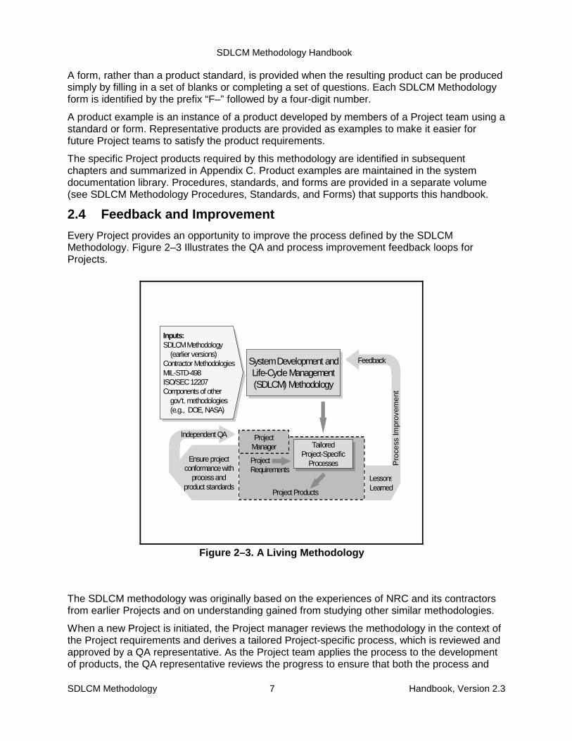
2.4 Feedback and Improvement
Every Project provides an opportunity to improve the process defined by the SDLCMMethodology. Figure 2–3 Illustrates the QA and process improvement feedback loops forProjects.
The SDLCM methodology was originally based on the experiences of NRC and its contractorsfrom earlier Projects and on understanding gained from studying other similar methodologies.
When a new Project is initiated, the Project manager reviews the methodology in the context ofthe Project requirements and derives a tailored Project-specific process, which is reviewed andapproved by a QA representative. As the Project team applies the process to the developmentof products, the QA representative reviews the progress to ensure that both the process and
SDLCM Methodology Handbook
SDLCM Methodology 8 Handbook, Version 2.3
Develop Systemwith InitialOperationCapability
Install and UseSystem
Maintain andEnhance System
as Necessary
System’sOperational
Concept
Figure 2–4. Illustrative System Life Cycle
the products conform to the approved standards. Any inconsistencies are reported to theProject manager. If the Project Manager fails to take appropriate action, the independent QAorganization elevates the report to higher levels of management. The QA process is defined inmore detail in Chapter 4.
Throughout the life of a Project, and especially as a part of Project closeout activities, lessonslearned from applying the SDLCM Methodology to the Projects are fed back to the SDLCMMethodology Team for analysis. It is primarily the actual Project experience of managers andteam members that sustains the process improvement feedback loop shown in the figure. Themechanism for reporting methodology deficiencies or suggesting improvements is described inAppendix A, Maintaining the SDLCM Methodology.
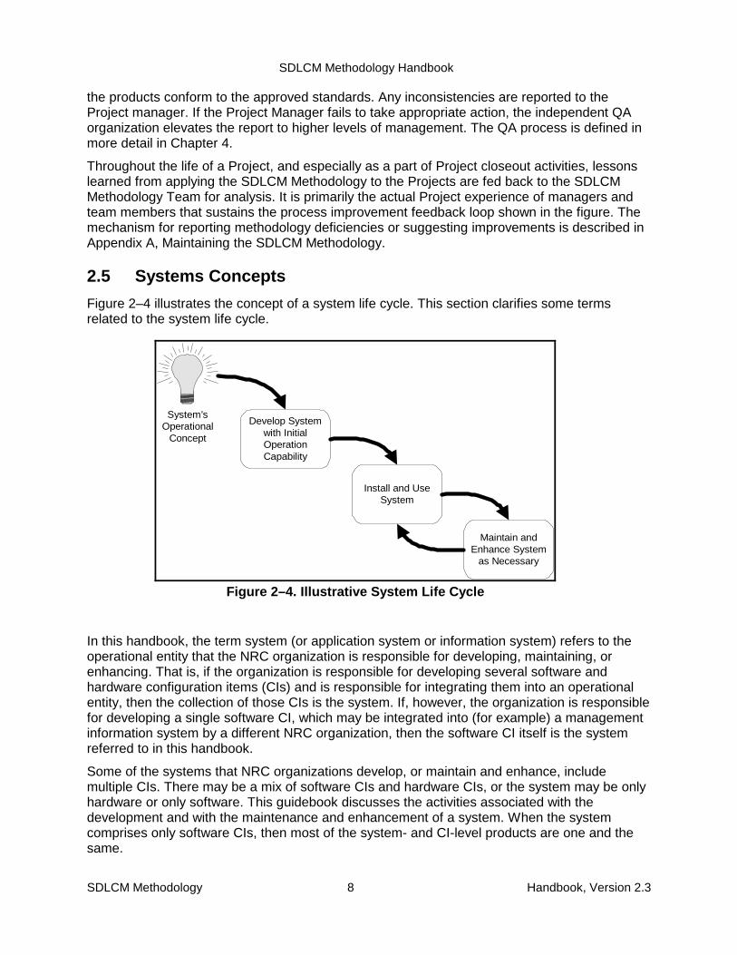
2.5 Systems Concepts
Figure 2–4 illustrates the concept of a system life cycle. This section clarifies some termsrelated to the system life cycle.
In this handbook, the term system (or application system or information system) refers to theoperational entity that the NRC organization is responsible for developing, maintaining, orenhancing. That is, if the organization is responsible for developing several software andhardware configuration items (CIs) and is responsible for integrating them into an operationalentity, then the collection of those CIs is the system. If, however, the organization is responsiblefor developing a single software CI, which may be integrated into (for example) a managementinformation system by a different NRC organization, then the software CI itself is the systemreferred to in this handbook.
Some of the systems that NRC organizations develop, or maintain and enhance, includemultiple CIs. There may be a mix of software CIs and hardware CIs, or the system may be onlyhardware or only software. This guidebook discusses the activities associated with thedevelopment and with the maintenance and enhancement of a system. When the systemcomprises only software CIs, then most of the system- and CI-level products are one and thesame.
SDLCM Methodology Handbook
SDLCM Methodology 9 Handbook, Version 2.3
Requirements SYSTEMDEVELOPMENT
SDLCMMethodology
Process Assets
Reusable or COTSProducts
New OperationalSystem
Figure 2–5. Development Context
Change Requests SYSTEMMAINTENANCE OR
ENHANCEMENT
SDLCMMethodology
Process Assets
Reusable or COTSProducts
Updated OperationalSystem
Operational System
Figure 2–6. Maintenance or Enhancement Context
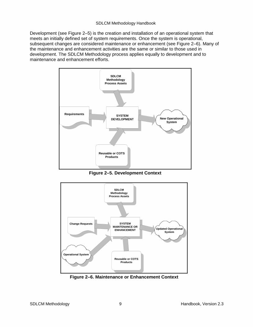
Development (see Figure 2–5) is the creation and installation of an operational system thatmeets an initially defined set of system requirements. Once the system is operational,subsequent changes are considered maintenance or enhancement (see Figure 2–6). Many ofthe maintenance and enhancement activities are the same or similar to those used indevelopment. The SDLCM Methodology process applies equally to development and tomaintenance and enhancement efforts.
SDLCM Methodology Handbook
SDLCM Methodology 10 Handbook, Version 2.3
3. Selecting an Appropriate SoftwareDevelopment Life-Cycle Model
The software development life cycle falls within the systems life cycle introduced in thepreceding chapter. It also falls within Component 3 (Design the Solution) and Component 4(Engineer the Solution) of the SCLCM Methodology. This chapter introduces four softwaredevelopment life-cycle models that may be applied to software development Projects at theNRC. Software enhancement Projects typically follow the same life-cycle model used for theoriginal development activities. The maintenance life cycle (Component 6) is discussed inChapter 3.2.
A life-cycle model comprises one or more phases (for example, a requirements definitionphase, a design phase, a test phase). Each phase is defined as the time interval between twoscheduled events. For example, in the waterfall life-cycle model, the design phase is defined asthe period between the software specification review (SSR) and the critical design review(CDR).
Within each phase, one or more activities are executed. For example, during the waterfallmodel’s design phase, the design activity is performed; the test planning activity may be doneat the same time. In most cases, activities neither begin nor end precisely at the phaseboundaries; rather, they overlap adjacent phases, as illustrated in Figure 3–1.
Notice that life-cycle phases are defined by time boundaries, whereas activities are defined bythe type of work being performed.
Various methods (or techniques) may be used in the performance of an activity. For example,object-oriented design is one proven design method; structured design is another.
This handbook does not mandate any particular software life-cycle model, and the order ofactivities described here is not intended to conform to any particular model. Few specificmethods are mandated for required activities. These decisions are left to the manager, whoselects an appropriate life-cycle model and activity-related methods and defines them in theProject Management Plan. This chapter contains guidance on selecting an appropriate,recommended life-cycle model and methods for many activities.
For convenience, Table 3–1 provides the definitions (see the Glossary) of several importantterms used extensively in this chapter.
Four life-cycle models are summarized in the following subsections:
� Waterfall development life-cycle model
� Incremental development life-cycle model
� Evolutionary development life-cycle model
� Package-based development life-cycle model

SDLCM Methodology Handbook
SDLCM Methodology 11 Handbook, Version 2.3
Figure 3–1. Phases and Activities
Table 3–1. Defining a Life CycleTerm Definition
Software life cycle “The period of time that begins when a software product is conceived andends when the software is no longer available for use.” [IEEE 610.12] a lifecycle is typically divided into life-cycle phases.
Life-cycle model A framework on which to map activities, methods, standards, procedures,tools, products, and services (for example, waterfall, and spiral).
Life-cycle phase A division of the software effort into non-overlapping time periods. Life-cyclephases are important reference points for the software manager. Multipleactivities may be performed in a life-cycle phase; an activity may span multiplephases.
Activity A unit of work that has well-defined entry and exit criteria. Activities canusually be broken into discrete steps.
Method A technique or approach, possibly supported by procedures and standards,that establishes a way of performing activities and arriving at a desired result.
3.1 Waterfall development Life-cycle Model
Table 3–2 Summarizes the Life Cycle Defined by the Waterfall development Model.

SDLCM Methodology Handbook
SDLCM Methodology 12 Handbook, Version 2.3
Figure 3–2. Waterfall Development Life-Cycle Model
Table 3–2. Summary of Waterfall Development Life-cycle ModelSummary descriptionand discussion
The waterfall (single-build) life-cycle model is essentially a once-through-do-each-step-once approach. Simplistically, determine user needs, definerequirements, design the system, implement the system, test, fix, anddeliver the system.
This model is illustrated in Figure 3–2.Advantages • Well-studied, well-understood, and well-defined
• Easy to model and understand• Easy to plan and monitor• Many management tools exist to support this life-cycle model
Disadvantages • Most if not all requirements must be known up front• Does not readily accommodate requirements changes• Product is not available for initial use until the Project is nearly done
Most appropriatewhen ...
• Project is similar to one done successfully before• Requirements are quite stable and well-understood• The design and technology are proven and mature• Total Project duration is relatively short (less than a year)
Customer does not need any interim releases

SDLCM Methodology Handbook
SDLCM Methodology 13 Handbook, Version 2.3
3.2 Incremental Development Life-cycle Model
Table 3–3 summarizes the life cycle defined by the incremental development model.
Table 3–3. Summary of Incremental Development Life-Cycle ModelSummarydescription anddiscussion
The incremental (multi-build) life-cycle model determines user needs anddefines a subset of the system requirements, then performs the rest of thedevelopment in a sequence of builds. The first build incorporates part of theplanned capabilities; the next build adds more capabilities; and so on, untilthe system is complete.
This model is illustrated in Figure 3–3.Advantages • Reduces risks of schedule slips, requirements changes, and acceptance
problems• Increases manageability• Interim builds of the product facilitate feeding back changes in
subsequent builds• Interim builds may be delivered before the final version is done; this
allows end users to identify needed changes• Breaks up development for long lead time Projects• Allows users to validate the product as it is developed• Allows software team to defer development of less well understood
requirements to later releases after issues have been resolved• Allows for early operational training on interim versions of the product• Allows for validation of operational procedures early• Includes well-defined checkpoints with customer and users via reviews
Disadvantages • Like the waterfall life-cycle model, most if not all requirements must beknown up front
• Sensitive to how specific builds are selected• Places products (particularly requirements) under configuration control
early in the life cycle, thereby requiring formal change control proceduresthat may increase overhead, particularly if requirements are unstable
Most appropriatewhen ...
• Project is similar to one done successfully before• Most of the requirements are stable and well-understood; but some
TBDs may exist• The design and technology are proven and mature• Total Project duration is greater than one year or customer needs interim
release(s)

SDLCM Methodology Handbook
SDLCM Methodology 14 Handbook, Version 2.3
Figure 3–3. Incremental Development Life-Cycle Model
3.3 Evolutionary Development Life-cycle Model
Table 3–4 Summarizes the Life cycle defined by the evolutionary development model.
Table 3–4. Summary of Evolutionary Development Life-Cycle ModelSummarydescription anddiscussion
Like the incremental development model, the evolutionary life-cycle modelalso develops a system in builds, but differs from the incremental model inacknowledging that the user needs are not fully understood and not allrequirements can be defined up front. In the evolutionary approach, userneeds and system requirements are partially defined up front, then arerefined in each succeeding build. The system evolves as the understandingof user needs and the resolution of issues occurs. Prototyping is especiallyuseful in this life-cycle model. (The evolutionary development life-cyclemodel is sometimes referred to as a spiral development model, but it is notthe same as Boehm’s spiral model. This model is also sometimes referredto as a prototyping life-cycle model, but it should not be confused with theprototyping technique.
This life-cycle model is illustrated in Figure 3–4.
SDLCM Methodology Handbook
SDLCM Methodology 15 Handbook, Version 2.3
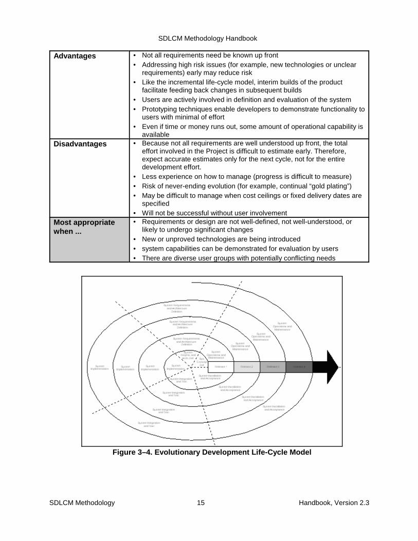
Figure 3–4. Evolutionary Development Life-Cycle Model
Advantages • Not all requirements need be known up front• Addressing high risk issues (for example, new technologies or unclear
requirements) early may reduce risk• Like the incremental life-cycle model, interim builds of the product
facilitate feeding back changes in subsequent builds• Users are actively involved in definition and evaluation of the system• Prototyping techniques enable developers to demonstrate functionality to
users with minimal of effort• Even if time or money runs out, some amount of operational capability is
availableDisadvantages • Because not all requirements are well understood up front, the total
effort involved in the Project is difficult to estimate early. Therefore,expect accurate estimates only for the next cycle, not for the entiredevelopment effort.
• Less experience on how to manage (progress is difficult to measure)• Risk of never-ending evolution (for example, continual “gold plating”)• May be difficult to manage when cost ceilings or fixed delivery dates are
specified• Will not be successful without user involvement
Most appropriatewhen ...
• Requirements or design are not well-defined, not well-understood, orlikely to undergo significant changes
• New or unproved technologies are being introduced• system capabilities can be demonstrated for evaluation by users• There are diverse user groups with potentially conflicting needs

SDLCM Methodology Handbook
SDLCM Methodology 16 Handbook, Version 2.3
3.4 Package-based Development Life-Cycle Model
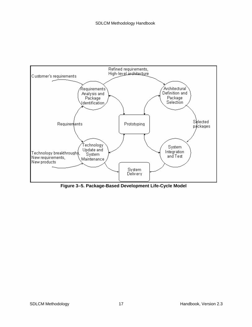
Table 3–5 summarizes the life cycle defined by the package-based development model.
Table 3–5. Summary of Package-based Development Life-Cycle ModelSummarydescription anddiscussion
• The package-based development life-cycle model is used for systemdevelopment based largely on the use of commercial-off-the-shelf andgovernment off-the-shelf products and reusable packages. Typically,some custom software development is needed to provide interfacesamong the non-developed items (NDIs).
• This model is illustrated in Figure 3–5.
Advantages • Lower cost than developing equivalent functionality from scratch• Cycle time also often lower than developing equivalent functionality from
scratch• Improves confidence in quality of the end product (since quality of NDIs
is already known)
Disadvantages • May result in compromises between desired functionality andfunctionality provided by NDIs
• Maintainability may be more of a challenge because source of NDIs maynot be the same NRC organization (for example, requires third party tomake changes, raises software CM issues when NDI vendor releasesupdated versions)
Most appropriatewhen ...
• A significant portion of the functionality of a system can be provided byNDIs
SDLCM Methodology Handbook
SDLCM Methodology 17 Handbook, Version 2.3
Figure 3–5. Package-Based Development Life-Cycle Model
SDLCM Methodology Handbook
SDLCM Methodology 18 Handbook, Version 2.3
4. Quality Assurance4.1 Purpose
Quality Assurance (QA) is a planned and systematic set of activities whose purpose is toprovide management with an independent view that approved processes are being used andthat high quality products are being produced by NRC Project teams.
Quality Assurance involves:
� Reviewing and auditing the activities and products to verify that they comply withpublished SDLCM Methodology procedures and standards
� Providing managers and Project teams managers with the results of these reviews andaudits
These review and audit activities occur throughout the life cycles of Projects and providemanagement with visibility needed to control the adherence to established plans, procedures,and standards.
4.2 Quality Assurance Goals
The Goals of NRC’s Quality Assurance Program are to ensure that:
� The Quality Assurance activities, and the corresponding resource allocation, areplanned.
� The products produced and activities performed at the NRC adhere to SDLCMMethodology procedures and standards.
� The results of any quality assurance activities are reported to the appropriate groups ina timely manner.
� Any noncompliance issues are corrected at the lowest possible level of management.
In pursuit of these goals at the Project level, Quality Assurance will:
� Support establishment of plans and procedures that meet contract and organizationpolicies and adherence to the SDLCM Methodology procedures and standards.
� Participate and conduct reviews and audits. This includes Project activities andproducts.
� Identify compliance issues. Escalate as required.
4.3 Process Implementation
Each organization, within NRC or under contract to NRC, that initiates a Project for development or maintenance of systems that have an IT component is subject to the SDLCMMethodology, will prepare and implement a Quality Assurance Plan (QAP). The QAP describesthe organization’s tailored approach to QA. It identifies the group(s) responsible for performingQA and the relationships between QA and other parts of the organization (such as ProgramManagement, Configuration Management, and the software development and maintenanceteams). The plan identifies resources and includes a schedule for performing the required
SDLCM Methodology Handbook
SDLCM Methodology 19 Handbook, Version 2.3
activities. Table 4–1 lists some important QA activities. The standard for preparation of theQMP is contained in S-2001.
4.4 Measurement and Analysis
Measuring the activities of the QA program permits management to evaluate the proficiency ofthe QA organization, which leads to better and more efficient planning of QA activities.Measurements may include but are not limited to:
� Completion of milestones for QA activities compared to a given Project schedule.
� Work completed, effort expended, and funds expended in the QA activities compared tothe planned work.
� Number of process and product reviews and audits compared to the planned work.
4.5 Verifying Implementation
Organizational management holds periodic reviews of the QA program. These reviews aredesigned to provide management with awareness of and insight into current QA activities.

SDLCM Methodology Handbook
SDLCM Methodology 20 Handbook, Version 2.3
Table 4–1. QA Activities
QA Activities QA Sub-activities Process Assurance Cycle (PAC) Activities: Document Project Approach
Deviation/Waiver Review
Pre-component Process Review
Component Orientation Meeting
In-progress Process Audit
Life-cycle Phase Audit
Product Inspection and Certification
Life-cycle Model Phase Review
Document Review
Audits: Configuration Audit
Document Pre-delivery Audit
System Product Delivery Audit
Inspection and Certification Meeting and Materials Audit
Other In-process Audits
Non-conformance Reporting and Corrective Action
Quality management Activities
Independent Test Monitoring
Training Monitoring
Data Collection and Analysis Monitoring
QA Activity Reports: Weekly Reports to management
Bi-weekly Reports to the Organizational Director of Quality
QA Calendar and Activity Schedules Input to Monthly Report
PAC Related Reports
Formal and Internal Review Report Formal Review
Formal Review Report
Internal Review
Internal Review Report
Audit Reports: Life-cycle Phase Audit Report
In-progress Audit Report
QA Records: QA Task Files
Task Area development Files
Task Area Maintenance Files
SDLCM Methodology Handbook
SDLCM Methodology 21 Handbook, Version 2.3
5. Configuration ManagementConfiguration Management (CM) Is a discipline of applying administrative and technicalprocedures throughout the systems life cycle to:
� Identify, define, and baseline software and associated documentation in a system(s)
� Control modifications to and releases of the baseline
� Record and report the status of the baselines and modification requests
� Ensure baseline completeness, consistency and correctness
� Control storage, handling, and delivery
CM includes the following major activities:
� CM process implementation—definition and documentation of the configurationmanagement activities
� Configuration identification—definition and identification of items subject to configurationcontrol
� Configuration control—evaluation, coordination, and approval or disapproval ofproposed changes to controlled items
� Configuration status accounting—recording and monitoring of changes to controlleditems
� Data management—maintenance of official correspondence records, CM records, andcontrolled documentation
� Configuration evaluation—verification that controlled items meet their assignedrequirements and are accurately documented
� In NRC Projects, configuration management is implemented at two levels, Applicationsystem, and Project/Task
5.1 CM Process Implementation
Each organization, within NRC or under contract to NRC, that initiates a Project fordevelopment or maintenance of systems that have an IT component and is subject to theSDLCM Methodology, is required to prepare and implement a Configuration Management Plan(CMP). The CMP describes the organization’s tailored approach to CM in conformance with theSDLCM Methodology. It identifies:
� The group(s) responsible for performing CM—such as the Configuration ManagementOffice (CMO), Configuration Control Boards (CCBs), and Project CM representatives
� The relationships between CM and other parts of the organization—such as ProjectManagement, Quality Assurance, and the software development and maintenanceteams
The plan identifies resources and includes a schedule for performing the required activities. Thestandards for preparation of the CMP are contained in S-2501.

SDLCM Methodology Handbook
SDLCM Methodology 22 Handbook, Version 2.3
5.2 Configuration Identification
Configuration identification consists of selecting the configuration items (CIs) for a system anddocumenting their functional and physical characteristics. It provides the basis for applyingmanagement controls to a system configuration, permitting the isolation of items to becontrolled, the tracking of their status, and the reporting of their configurations. The CMO, whois defined as the lead by the Overall Project Manager as the Technical Subject Matter Expertfor CM activities, identifies those new software and hardware CI s for the Project. The CMO incooperation with the Technical Project Manager establishes a scheme for the identification ofsoftware configuration items (SWCIs) and hardware configuration items (HWCIs) and theirversions to be controlled for the Project.
For existing systems which are supported by legacy application systems, configurationidentification begins with the documentation that established the baseline and its version, acomplete inventory of items (including software) requiring conversion, rewrite, or transition, andassociated hardware and communications (as required).
For new development, configuration identification begins with requirements that provide thework definition.
Configuration identification also applies to acquired hardware, communications equipment,Commercial-Off-The-Shelf (COTS) software, and documentation. A thorough configurationidentification system is essential to monitoring, tracking, and implementing changes.
CI selection involves grouping system components into a unit subject to CM control. Thisactivity is performed for software and hardware CI s by the systems engineering group lead bythe Technical Project Manager, with approval from the appropriate Configuration Control Board(CCB). Non-software and hardware components (e.g., Management Directives, Rules, etc.) arethe responsibility of the Project Level CCB with oversight by the System ExecutiveSponsor/Overall Project Manager. Certain functional, performance, and physical characteristicsare allocated to each CI. A CI that is too large results in decreased visibility and ineffectivecontrol; one that is too small or placed under configuration control too early produces theopposite result: visibility that is at a very detailed level for the defined component and controlthat is excessive and therefore inefficient. For effective CM, CIs must be defined carefully andplaced under configuration control at the appropriate time.
The following are guidelines by which CIs should be selected:
� Small and well-defined set of interfaces with other CIs
� Single source, such as a development group or contractor, responsible for providing theCI
� Largest entity that provides adequate client and management visibility into thedevelopment process
� Common schedule for acquisition, development, testing, and delivery of subordinateelements
� Independent operational or user interfaces from the user’s point of view
� Critical item with respect to safety, security, reliability, or other factors that requirespecific management attention
� As a single entity, requires maintenance, training, and logistical support
� Specific requirements for performance controls

SDLCM Methodology Handbook
SDLCM Methodology 23 Handbook, Version 2.3
� High degree of change or modification expected once the CI becomes operational
Because each CI requires its own baseline documentation and configuration control,identification of too many CIs must be avoided. If too many CIs are identified, systemdevelopment will be excessively controlled and CM will be more complex and costly thannecessary.
5.3 Configuration Control
Configuration control is the process of evaluating, approving or disapproving, and monitoringthe implementation of changes to baselines during development, operation, or maintenance.This function includes the following:
1. Identification and recording of change proposals (SDLCM Methodology Form F–2502)
� Approval or disapproval of the request
� Implementation
� Verification
� Release of the modified software item
2. Establishing an audit trail that identifies
� Each modification
� Reason for the modification
� Authorization of the modification
The CMO controls and audits all access to the controlled system items. Activities that handlesafety or security critical functions requiring special handling are controlled in accordance withestablished NRC guidelines.
5.3.1 Responsibility and Process Flow
Configuration control is the responsibility of both the CMO and the CCB with oversight from theExecutive Sponsor and Overall Project Manager.
The CMO is responsible for maintaining the integrity of all baselines. The CMO ensures thatonly NRC-approved changes are incorporated into baselines. CM-controlled baselines areupdated using change control procedures that provide for systematic evaluation, coordination,and formal disposition of proposed changes and for implementation of changes that areapproved.
The CCB is the heart of the configuration management process. The CCB provides a structuredreview process of requirements changes, problem or risk areas, and work in progress. TheCCB is established under the authority and control of the NRC Executive Sponsor and functionsin accordance with the CM program. The NRC Executive Sponsor, or a designated alternate,chairs the CCB, which is made up of technical managers, a QA representative, a CMrepresentative (who serves as secretary), and other subject matter experts as required for aproper evaluation.
See SDLCM Methodology procedure P–2502, Change Proposal, for a detailed description ofthe change process and the steps that must be followed to propose and incorporate a change.

SDLCM Methodology Handbook
SDLCM Methodology 24 Handbook, Version 2.3
See SDLCM Methodology Procedure P–2501, Configuration Control Board, for a detaileddescription of the steps in the CCB process.
5.3.2Change Vehicles
Changes may be requested using several different vehicles as determined by the type ofchange. Note that some Projects may not require all of these mechanisms, and others mayneed additional vehicles. The following types of change requests are provided:
� Change Proposal (CP). A formal request to change an approved baseline (software,hardware, equipment, or their specification). See SDLCM methodology ProcedureP–2502, Change Proposal, and Form F–2502, Change Proposal Form, for additionalinformation.
� Request for Deviation or Waiver. A formal request to deviate from a standardmethodology process or to be granted a waiver from following a standard process. Inthe context of CM the deviation or waiver typically requests a departure from establishedconfiguration baseline requirements. This type of request is discussed further in thechapter on Quality Assurance. See SDLCM Methodology procedure P–2001 deviationsand waivers, for additional information.
� Problem Report (PR). A formal report of a problem detected during development,maintenance or operation of authorized systems. See SDLCM Methodology formsF–2251 (Problem Reports) and F–2252 (Problem Report Logs).
5.3.3Change Management
The management of proposed changes to a baseline is a critical part of system maintenanceand, hence, of Component 6, Service the Solution, of the SDLCM Methodology. Therefore, thedetails of this element of configuration management are included in Section 11.2.
5.3.4 Release Management
The CMO formally controls the release and delivery of software products and documentation.Only formal agency guidance, and certified software and builds are formally delivered andimplemented. Master copies of code and documentation are maintained for the life of theapplication system software product through the agency Central CM Library function. A priorrelease version and inactive application systems awaiting decommissioning are archived.
Planning and managing what changes go into each release are critical parts of systemmaintenance and, hence, of Component 6, service the solution, of the SDLCM Methodology.Therefore, the details of this element of configuration management are included in Section11.3.
5.4 Configuration Status Accounting
Configuration status accounting is the recording, monitoring, and reporting of all changes toestablished baselines. The objectives of configuration status accounting are to ensure that:
� All approved changes are reflected in the affected baselines
� No baseline includes changes that have not been approved

SDLCM Methodology Handbook
SDLCM Methodology 25 Handbook, Version 2.3
The CMO generates management records and status reports that show the status and historyof controlled items including software baselines. Status reports include the number of changesfor a Project, latest versions, release identifiers, number of releases, and the differencesbetween the releases.
5.5 Data Management
Data Management (DM) is closely related to configuration status accounting. Whileconfiguration status accounting focuses on recording and monitoring changes to controlleditems, DM focuses on maintaining official correspondence records, CM records, and controlleddocumentation.
5.6 Configuration Evaluation
Configuration evaluation involves a series of inspections, tests, reviews, and audits to ensurethat the manual processes and automated processes of the system, the data, and theguidance and automated documentation accurately represent the approved configurationbaselines.
The functional completeness of the system’s automated and manual process products (e.g.,software code and policy/guidance) as compared to their defined requirements is determinedusing the Functional Configuration Audit (FCA). The FCA is the formal examination of functionalcharacteristics of a configuration item, prior to acceptance, to verify that the item has achievedthe requirements specified in its functional and allocated configuration documentation.
The physical completeness of the systems products (that is, whether all defined products wereproduced to the specifications called for by the required standards and guidance defined by theProject Management Plan and Software Development Plan) are determined using the PhysicalConfiguration Audit (PCA). The PCA is a formal examination. The PCA for the as-builtconfiguration of the automated components (application system code and executables) is theformal examination of the CI s against their technical documentation to establish and verify theCI’s product baseline.
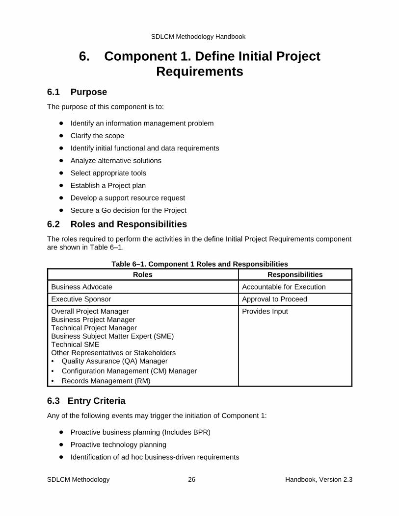
SDLCM Methodology Handbook
SDLCM Methodology 26 Handbook, Version 2.3
6. Component 1. Define Initial ProjectRequirements
6.1 Purpose
The purpose of this component is to:
� Identify an information management problem
� Clarify the scope
� Identify initial functional and data requirements
� Analyze alternative solutions
� Select appropriate tools
� Establish a Project plan
� Develop a support resource request
� Secure a Go decision for the Project
6.2 Roles and Responsibilities
The roles required to perform the activities in the define Initial Project Requirements componentare shown in Table 6–1.
Table 6–1. Component 1 Roles and ResponsibilitiesRoles Responsibilities
Business Advocate Accountable for Execution
Executive Sponsor Approval to Proceed
Overall Project ManagerBusiness Project ManagerTechnical Project ManagerBusiness Subject Matter Expert (SME)Technical SMEOther Representatives or Stakeholders• Quality Assurance (QA) Manager• Configuration Management (CM) Manager• Records Management (RM)
Provides Input
6.3 Entry Criteria
Any of the following events may trigger the initiation of Component 1:
� Proactive business planning (Includes BPR)
� Proactive technology planning
� Identification of ad hoc business-driven requirements
SDLCM Methodology Handbook
SDLCM Methodology 27 Handbook, Version 2.3
� Identification of ad hoc technology-driven requirements
Note that these events occur as part of the “Conduct Strategic Technology and BusinessSystems Planning” box in Figure 2–1, and therefore are outside the scope of the SDLCMMethodology and this handbook. Any of these triggers may be driven by changes in:
� Cost
� Technology
� External mandate (for example, laws)
6.4 Input, Activities, and Outputs
The inputs to this component are as follows:
� Project Description (new and maintenance)
� Approved budget allocation
� Advance Procurement Plan
� Office or Regional approval
� Responsible Project contact
� Project responsibilities
� Technical Reference Model
� Enterprise Model
� Tool Inventory
� Any available Business Process Reengineering (BPR) documents
Figure 6–1 illustrates the flow of the following activities:
8. Clearly Identify Information Management Problem
9. Clarify Project Scope
10. Establish a Project Plan
11. Generate the Software Development Plan
12. Notify Records Management Branch to Review Records Management Requirements
13. Identify Requirements
14. Analyze Alternatives
15. Review Toolkit
16. Develop Support Resource Request
17. Plan for Deployment
18. Review (Component 1)

SDLCM Methodology Handbook
SDLCM Methodology 28 Handbook, Version 2.3
PMPF-1061F-1601
1.1 ClearlyIdentify
InformationManagement
Problem
1.2 ClarifyProject Scope
1.6 IdentifyRequirements
1.7 AnalyzeAlternatives
1.3 Establish aProject Plan andProject Support
Controls
1.8 Review theToolkit
1.9 DevelopSupport
ResourceRequest
1.10 Plan forDeployment
Project Charter, S-1051System Requirements Specification (SRS), S-3051Current System Assessment Document (CSAD), S-3052System Operations Concept (SOC), S-3053Alternatives Analysis Document (AAD), S-3054Project Management Plan (PMP), S-1052Quality Assurance Plan (QAP), S-2001Configuration Management Plan (CMP), S-3501Software Development Plan (SDP), S-1057Support Resource Acquisition Request and Commitment Form, F-1061Environment Change Request Form, F-1601Tactical Integration Plan (TIP), S-5051Notification of Electronic Information System Design or Modification, NRC Form 616Records Retention and Disposition Authority, NRC Form 331Information System Description, NA Form 14028Request for Records Disposition Authority, SF 115SDLCM Methodology Deviation or Waiver Form, F-2010Enterprise Model Change Request Form, F-2070Go or No Go Decision for Project Form, Component 1, F-1151
Records ManagementRequirements
ProjectCharter
SRS(Scope)
SOC
SRS (System Requirements)F-2070
PMP(F-2010)
1.5 NotifyRecords
ManagementBranch to review
RecordsManagementRequirements
NRC Form 331NRC Form 616NA Form14028SF115
AAD(S-3054))
CSAD(S-3052)
Environment
SDP(S-1057)
TIP
1.11 Review(Go or No GoDecision for
Project Form,Component 1,
F-1151)
Component 2Acquire Support
Resources
Go No Go
Requirement forProject
1.4 Generate theSoftware
DevelopmentPlan
Environment
SDP(S-1057)
Figure 6–1. Component 1

SDLCM Methodology Handbook
SDLCM Methodology 29 Handbook, Version 2.3
As the figure suggests, many of the activities can be performed in parallel. For example, Activity1.6, Establish a Project Management Plan, may be started as soon as there is enoughinformation to begin planning; the activity cannot be completed, however, until all requiredplanning information has been provided (for example, all system requirements must be knownand all tool requirements must be determined).
The activities are described in more detail in Section 6.7.
Figure 6–1 also summarizes the outputs of all Component 1 activities in the central data store.
Appendix C includes a summary description of all products of NRC Projects, indicates withinwhich components each product is created and updated, and specifies which products arerequired. The Current System Assessment Document (CSAD) is required to prioritizerequirements even if there is no current automated system to be assessed. If there are no newrequirements and only a relatively minor change is required, the prioritization can bedocumented adequately in the Software Engineering Notebook (SEN), which would be the casefor a maintenance change. The SRS, Project Management Plan (PMP), and Tactical IntegrationPlan (TIP) are all begun as part of activities within this component and are all updated insubsequent components.
The products, whose standard and form numbers are shown in the figure, are described inmore detail in the companion volume SDLCM Methodology Procedures, Standards, and Forms.
6.5 Techniques and ToolsThe activities of Component 1 are supported by the following techniques.
� Business Area Analysis
� Business Process Reengineering
� Data Modeling
� Process Modeling
� Structured Walkthrough
� Peer Review
Refer to the current SDLCM Methodology Tool Inventory for the recommended set of tools.
6.6 Exit CriteriaComponent 1 is complete when:
� All major products have been reviewed (structured walkthrough or peer review)
� All major products have been inspected by QA and certified to conform with Projectstandards
� All products have been placed under Project-Level CM control
� Information has been shared
� Issues have been resolved
� There is management buy-in to move forward
� There are no reasons to stop this Project now

SDLCM Methodology Handbook
SDLCM Methodology 30 Handbook, Version 2.3
6.7 Component 1 Activity Details
The following pages provide detailed activities of Component 1, Define Initial ProjectRequirements.

SDLCM Methodology Handbook
SDLCM Methodology 31 Handbook, Version 2.3
Activity 1.1: Clearly Identify Information Management Problem
See Figure 6–2. Using the Outputs from the Strategic Technology and Business systemsPlanning Activities (Which Are Outside the Scope of this Methodology):
1. Determine What Business Processes and Organizations Are Within the Scope of thisProject.
2. Determine the Business Goals, Objectives, or Problems to Be Achieved.3. Summarize the Findings in the Project Charter.
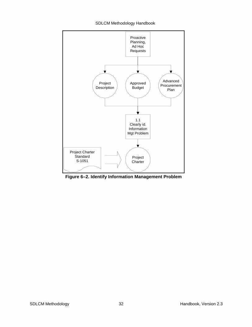
SDLCM Methodology Handbook
SDLCM Methodology 32 Handbook, Version 2.3
ApprovedBudget
AdvancedProcurement
Plan
ProjectCharter
ProjectDescription
1.1Clearly id.
InformationMgt Problem
ProactivePlanning,Ad Hoc
Requests
Project CharterStandardS-1051
Figure 6–2. Identify Information Management Problem
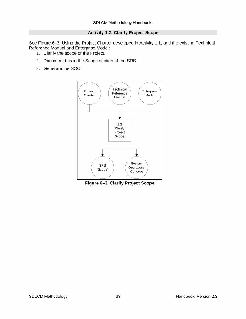
SDLCM Methodology Handbook
SDLCM Methodology 33 Handbook, Version 2.3
ProjectCharter
TechnicalReference
Manual
EnterpriseModel
1.2ClarifyProjectScope
SRS(Scope)
SystemOperations
Concept
Figure 6–3. Clarify Project Scope
Activity 1.2: Clarify Project Scope
See Figure 6–3. Using the Project Charter developed in Activity 1.1, and the existing TechnicalReference Manual and Enterprise Model:
1. Clarify the scope of the Project.
2. Document this in the Scope section of the SRS.
3. Generate the SOC.
SDLCM Methodology Handbook
SDLCM Methodology 34 Handbook, Version 2.3
Activity 1.3: Establish a Project Plan and Project Support Controls (CM, QA)
See Figure 6–4. Using the Project Charter, the SRS, and the System Operations Concepts asInput:
1. Develop a Project Management plan. On the basis of the complexity of the Project,choose an appropriate life-cycle model to develop the Project. For example, if this is avery straightforward enhancement, a waterfall approach may be appropriate. If therequirements are not well defined, then an iterative development approach with activeinvolvement of the customer may be more appropriate.
2. Use any tools and methods available to estimate the amount of effort required todevelop the needed functionality.
3. On the basis of the amount of effort required and the complexity of the Project, developa tactical plan. That is, define a Project team with the right mix of senior and juniorpeople, and define their roles and responsibilities.
4. Define intermediate milestones and products.
5. Define Project critical success measures, including performance requirements.
6. Evaluate and plan for records management.
7. Specify CM requirements and package results in the CMP.
8. Specify QA requirements and package results in the QAP.
9. Package the results of your work in the Project Management Plan.
10. Have QA review your plan and make any necessary changes.
11. Have Project-Level CM capture your plan in the Project-Level CM library.
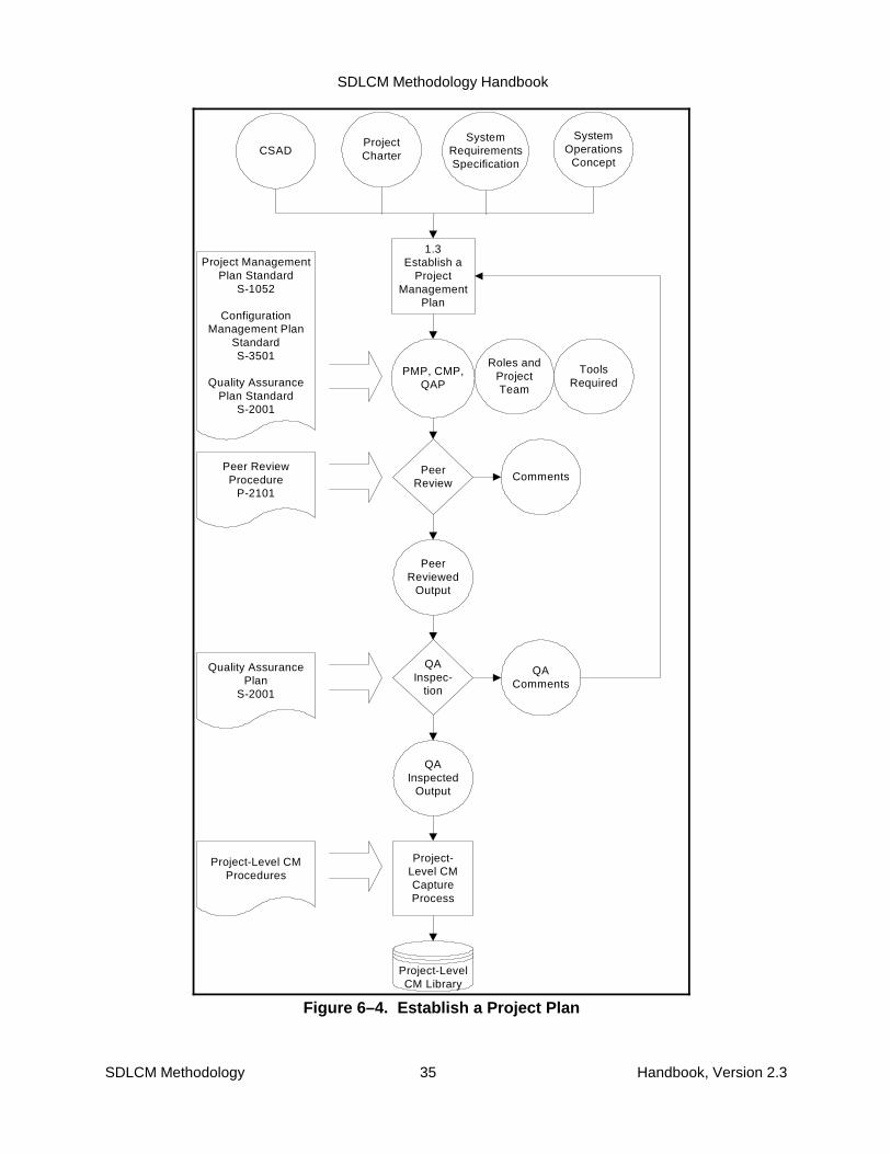
SDLCM Methodology Handbook
SDLCM Methodology 35 Handbook, Version 2.3
SystemOperations
Concept
1.3Establish a
ProjectManagement
Plan
ProjectCharter
PMP, CMP,QAP
Roles andProjectTeam
ToolsRequired
SystemRequirementsSpecification
PeerReview
PeerReviewed
Output
QAInspec-
tion
QAInspected
Output
Project-Level CMCaptureProcess
Project ManagementPlan Standard
S-1052
ConfigurationManagement Plan
StandardS-3501
Quality AssurancePlan Standard
S-2001
Project-LevelCM Library
Peer ReviewProcedure
P-2101
Comments
Quality AssurancePlan
S-2001
QAComments
Project-Level CMProcedures
CSAD
Figure 6–4. Establish a Project Plan

SDLCM Methodology Handbook
SDLCM Methodology 36 Handbook, Version 2.3
ProjectManagement
Plan
TechnicalReference
Model
1.4Generate
SDP
SoftwareDevelopment
Plan
Figure 6–5. Generate the SoftwareDevelopment Plan
Activity 1.4: Generate the Software Development Plan
See Figure 6–5. Using the Project Management Plan developed in Activity 1.3, the existingTechnical Reference Model, schedule, and information influencing appropriate life-cycle, generate the Software Development Plan.
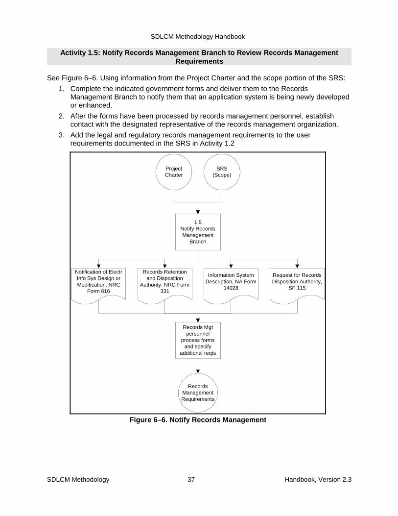
SDLCM Methodology Handbook
SDLCM Methodology 37 Handbook, Version 2.3
ProjectCharter
1.5Notify RecordsManagement
Branch
RecordsManagementRequirements
SRS(Scope)
Records Mgtpersonnel
process formsand specify
additional reqts
Records Retentionand Disposition
Authority, NRC Form331
Information SystemDescription, NA Form
14028
Request for RecordsDisposition Authority,
SF 115
Notification of ElectrInfo Sys Design orModification, NRC
Form 616
Figure 6–6. Notify Records Management
Activity 1.5: Notify Records Management Branch to Review Records ManagementRequirements
See Figure 6–6. Using information from the Project Charter and the scope portion of the SRS:
1. Complete the indicated government forms and deliver them to the RecordsManagement Branch to notify them that an application system is being newly developedor enhanced.
2. After the forms have been processed by records management personnel, establishcontact with the designated representative of the records management organization.
3. Add the legal and regulatory records management requirements to the userrequirements documented in the SRS in Activity 1.2
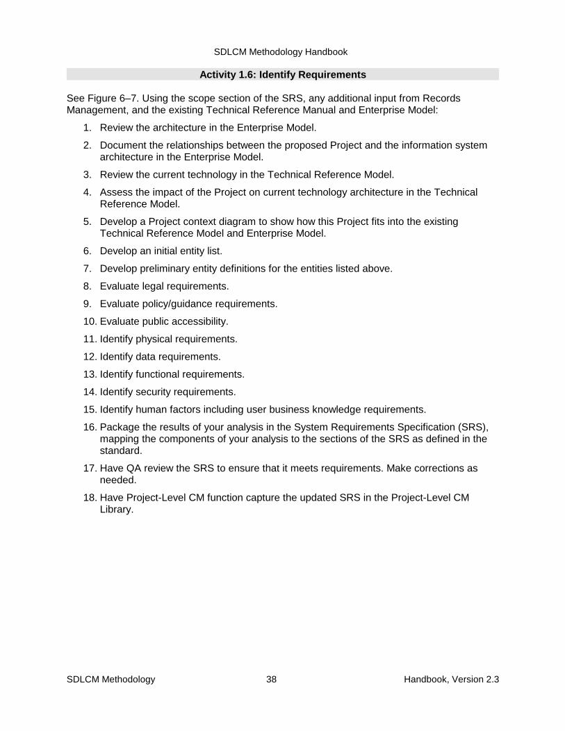
SDLCM Methodology Handbook
SDLCM Methodology 38 Handbook, Version 2.3
Activity 1.6: Identify Requirements
See Figure 6–7. Using the scope section of the SRS, any additional input from RecordsManagement, and the existing Technical Reference Manual and Enterprise Model:
1. Review the architecture in the Enterprise Model.
2. Document the relationships between the proposed Project and the information systemarchitecture in the Enterprise Model.
3. Review the current technology in the Technical Reference Model.
4. Assess the impact of the Project on current technology architecture in the TechnicalReference Model.
5. Develop a Project context diagram to show how this Project fits into the existingTechnical Reference Model and Enterprise Model.
6. Develop an initial entity list.
7. Develop preliminary entity definitions for the entities listed above.
8. Evaluate legal requirements.
9. Evaluate policy/guidance requirements.
10. Evaluate public accessibility.
11. Identify physical requirements.
12. Identify data requirements.
13. Identify functional requirements.
14. Identify security requirements.
15. Identify human factors including user business knowledge requirements.
16. Package the results of your analysis in the System Requirements Specification (SRS),mapping the components of your analysis to the sections of the SRS as defined in thestandard.
17. Have QA review the SRS to ensure that it meets requirements. Make corrections asneeded.
18. Have Project-Level CM function capture the updated SRS in the Project-Level CMLibrary.
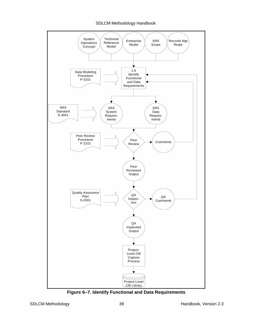
SDLCM Methodology Handbook
SDLCM Methodology 39 Handbook, Version 2.3
TechnicalReference
Model
EnterpriseModel
SRSScope
1.6Identify
Functionaland Data
Requirements
SRSSystemRequire-
ments
PeerReview
PeerReviewed
Output
QAInspec-
tion
QAInspected
Output
Project-Level CMCaptureProcess
SRSStandardS-3051
Project-LevelCM Library
Data ModelingProcedure
P-3101
Comments
Quality AssurancePlan
S-2001QA
Comments
Peer ReviewProcedure
P-2101
Records MgtReqts
SystemOperations
Concept
SRSData
Require-ments
Figure 6–7. Identify Functional and Data Requirements

SDLCM Methodology Handbook
SDLCM Methodology 40 Handbook, Version 2.3
Activity 1.7: Analyze Alternatives
See Figure 6–8. This activity includes the assessment of current systems, the analysis ofalternative approaches for satisfying the requirements, and the development of an operationalconcept.
Using the requirements documented in the SRS, determine whether it is better to enhance,supplement, or replace any existing systems. Use a process such as the following:
1. Create a table for assessing the current system(s). Use the sample shown in the CSADstandard.
2. Review the list of requirements in the SRS. Enter these functions in the requirementscolumn of the table.
3. Identify the existing systems that might be used to help solve the informationmanagement problem. For each existing system, determine which requirements aresatisfied and enter those in the appropriate column of the table. Then note theremaining requirements satisfied by none of the current systems in the final column ofthe table.
4. Document the results of the assessment in the CSAD. If there is no current system, theCSAD is still required to the level of completion of Section 4.
5. Validate the requirements defined in the SRS by comparing them to the SystemOperations Concept (S-3052), created in activity 1.2. If additional requirements arediscerned, update the SRS, as appropriate.
6. Analyze the alternative approaches for satisfying the remaining requirements. Considerthe advantages and disadvantages of enhancing, supplementing, or replacing eachcurrent system that was assessed and options for developing a new system if nothing isreusable. This analysis continues with the examination of using GOTS or COTS, ordeveloping new to satisfy the prioritized requirements. The examination should weightand record sufficient information to determine the best options for satisfying therequirements and document the costs based on a five year design/operation time frame,the risks and the benefits of each alternative (see Appendix B, Management Directive2.2, Capital Planning and Investment Control). Document the results in the AlternativesAnalysis Document (S-3054).
7. Based on Alternatives Analysis, update System Operations Concept (S-3052), asappropriate, to reflect best approach resulting from the analysis.
8. Have QA review the Assessment of Current System, Analysis of Alternatives, andSystem Operations Concept and recommend any necessary corrections.
9. Have Project-Level CM function capture these documents in the Project-Level CMLibrary.

SDLCM Methodology Handbook
SDLCM Methodology 41 Handbook, Version 2.3
SRSSystemRequire-ments
SRSData
Require-ments
SRSContextDiagram
SRSEntity List
SRSEntity
Definitions
1.7Analyze
Alternatives
CurrentSystem
Assessment
Analysis ofAlternatives
SystemOperationsConcept(update)
PeerReview
PeerReviewed
Output
QAInspec-
tion
QAInspected
Output
Project-Level CMCaptureProcess
Current SystemAssessment Doc
StandardS-3052
Project-LevelCM Library
Peer ReviewProcedure
P-2101 Comments
Quality AssurancePlan
S-2001QA
Comments
Project-Level CMProcedures
SystemOperationsConcept
Alternatives AnalysisDocument
S-3054
Figure 6–8. Analyze Alternatives
SDLCM Methodology Handbook
SDLCM Methodology 42 Handbook, Version 2.3
SystemOperationsConcept
1.8ReviewToolkit
ToolsRequired
Figure 6–9. Review the Toolkit
Activity 1.8: Review the Toolkit
See Figure 6–9. Using the results of your Analysis of Alternatives and the System OperationsConcept:
� Review the Tool Inventory to select preferred tools or identify new tool requirements.This information will be used to identify your resources request in Activity 1.9.
� Update SDP, as needed.

SDLCM Methodology Handbook
SDLCM Methodology 43 Handbook, Version 2.3
1.9Identify
Personneland OtherResources
Support ResourceAcq. RequestForm F-1061
ProjectManagement
Plan
Identify Toolsand
Technologies
EnvironmentChange Request
Form F-1601
SoftwareDevelopment
Plan
ProjectManagement
Plan(Schedules)
Figure 6–10. Develop Support ResourceRequest
Activity 1.9: Develop Support Resource Request
See Figure 6–10. Using the results of your detailed planning (as documented in the ProjectManagement Plan), which shows the effort, people, computer hardware and softwarerequirements, and any methods or tools necessary, request the resources you will need to besuccessful.
1. Update PMP schedules based on SDP updates.
2. Use an Environment Change Request Form and the process defined in the EnvironmentChange Procedure to request any new tools or technologies.
3. Use a Support Resource Acquisition Request and Commitment Form (F-1061), IfNeeded, to request personnel and any other resources.
4. Identify procurement needs in detail.
5. Negotiate to obtain a commitment for the resources you need.
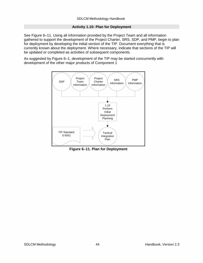
SDLCM Methodology Handbook
SDLCM Methodology 44 Handbook, Version 2.3
ProjectTeam
Information
TacticalIntegration
Plan
1.10Perform
InitialDeployment
Planning
ProjectCharter
Information
SRSInformation
PMPInformation
TIP StandardS-5051
SDP
Figure 6–11. Plan for Deployment
Activity 1.10: Plan for Deployment
See Figure 6–11. Using all information provided by the Project Team and all informationgathered to support the development of the Project Charter, SRS, SDP, and PMP, begin to planfor deployment by developing the initial version of the TIP. Document everything that iscurrently known about the deployment. Where necessary, indicate that sections of the TIP willbe updated or completed as activities of subsequent components.
As suggested by Figure 6–1, development of the TIP may be started concurrently withdevelopment of the other major products of Component 1
SDLCM Methodology Handbook
SDLCM Methodology 45 Handbook, Version 2.3
Activity 1.11: Review (Component 1)
See Figure 6–12. Review the Project to make a GO or NO-GO Decision.
1. Justify the Project. Review the need for the Project, the cost in terms of personnel andresources, and the return on investment for the Project. Consider the best case scenarioand the worst case scenario of moving forward with the Project.
2. Complete the form required obtaining approval to proceed.
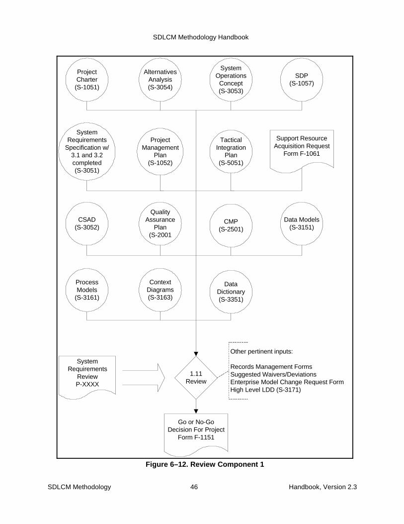
SDLCM Methodology Handbook
SDLCM Methodology 46 Handbook, Version 2.3
1.11Review
Go or No-GoDecision For Project
Form F-1151
SystemRequirements
Specification w/3.1 and 3.2completed(S-3051)
AlternativesAnalysis(S-3054)
ProjectManagement
Plan(S-1052)
Support ResourceAcquisition Request
Form F-1061
TacticalIntegration
Plan(S-5051)
ProjectCharter(S-1051)
SystemOperations
Concept(S-3053)
SDP(S-1057)
SystemRequirements
ReviewP-XXXX
QualityAssurance
Plan(S-2001
CSAD(S-3052)
CMP(S-2501)
Data Models(S-3151)
ContextDiagrams(S-3163)
ProcessModels
(S-3161)
DataDictionary(S-3351)
Other pertinent inputs:
Records Management FormsSuggested Waivers/DeviationsEnterprise Model Change Request FormHigh Level LDD (S-3171)
Figure 6–12. Review Component 1

SDLCM Methodology Handbook
SDLCM Methodology 47 Handbook, Version 2.3
7. Component 2. Acquire Support Resources7.1 Purpose
The purpose of this Component is to obtain the necessary resources to ensure timely andeffective progress on the Project, including:
� Staff
� Technology
� Contractors
� Training
7.1.1 Projects and Funding VehiclesIt is very important to understand that NRC’s SDLCM Methodology deals with Projects andproducts, not with contracts and deliverables. This section of the chapter on Component 2,Acquire Support Resources, relates the Project-oriented methodology to the contractingprocess. The remainder of the documentation set of the SDLCM Methodology is free ofcontract-dependent terminology, so it can be applied on any contract vehicle.
NRC’s typical mechanism for providing a source of Project funding to a contractor is theContract Line Item (CLIN).
The three terms CLIN/Delivery Order, Project, and system have three distinct meanings:
� A CLIN/Delivery Order is a vehicle for defining discreet portions of the work to beperformed under contract and for applying funding for a Project, part of a Project, ormultiple Projects.
� a Project is an undertaking requiring an organized effort, focused on developing ormaintaining a specific product. Typically, a Project has its own funding, cost accounting,and product schedule. That is, the Project is the work to be done and the personnelassigned to perform the work; it is not the same as the product (for example, a system)that the Project personnel are to produce.
� a system is an operational entity. An application system or information system supportsa business requirement.
A Project produces Products. A CLIN/Delivery Order requires the delivery of Deliverables.
NRC designed the SDLCM methodology to be applied to a Project rather than to aCLIN/Delivery Order.
7.1.2 Funding Approaches and Project Products
A Project may be funded all at once under a single CLIN or Delivery Order, incrementally undera single CLIN or Delivery Order, or incrementally under a sequence of CLINs.
The document products specified by the SDLCM Methodology are to be developed as productsof a complete Project, not necessarily as deliverables of a single CLIN/Delivery Order. If aCLIN/Delivery Order funds only a portion of a Project, it then stands to reason that not allProject products will be delivered under that CLIN/Delivery Order. In any case, the OverallProject Manger is responsible for ensuring that the Project products (as specified by theSDLCM Methodology) are produced (or formally waived) whether or not they are contractually
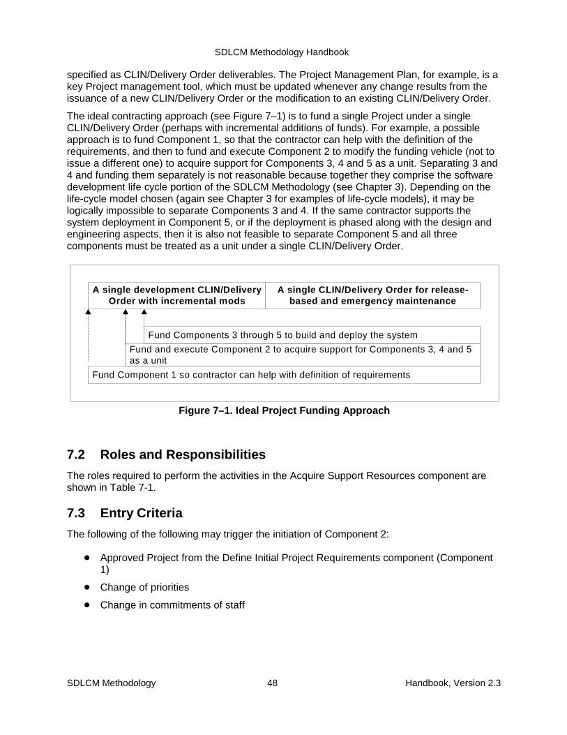
SDLCM Methodology Handbook
SDLCM Methodology 48 Handbook, Version 2.3
A single development CLIN/DeliveryOrder with incremental mods
A single CLIN/Delivery Order for release-based and emergency maintenance
Fund Components 3 through 5 to build and deploy the system
Fund and execute Component 2 to acquire support for Components 3, 4 and 5as a unit
Fund Component 1 so contractor can help with definition of requirements
Figure 7–1. Ideal Project Funding Approach
specified as CLIN/Delivery Order deliverables. The Project Management Plan, for example, is akey Project management tool, which must be updated whenever any change results from theissuance of a new CLIN/Delivery Order or the modification to an existing CLIN/Delivery Order.
The ideal contracting approach (see Figure 7–1) is to fund a single Project under a singleCLIN/Delivery Order (perhaps with incremental additions of funds). For example, a possibleapproach is to fund Component 1, so that the contractor can help with the definition of therequirements, and then to fund and execute Component 2 to modify the funding vehicle (not toissue a different one) to acquire support for Components 3, 4 and 5 as a unit. Separating 3 and4 and funding them separately is not reasonable because together they comprise the softwaredevelopment life cycle portion of the SDLCM Methodology (see Chapter 3). Depending on thelife-cycle model chosen (again see Chapter 3 for examples of life-cycle models), it may belogically impossible to separate Components 3 and 4. If the same contractor supports thesystem deployment in Component 5, or if the deployment is phased along with the design andengineering aspects, then it is also not feasible to separate Component 5 and all threecomponents must be treated as a unit under a single CLIN/Delivery Order.
7.2 Roles and Responsibilities
The roles required to perform the activities in the Acquire Support Resources component areshown in Table 7-1.
7.3 Entry Criteria
The following of the following may trigger the initiation of Component 2:
� Approved Project from the Define Initial Project Requirements component (Component1)
� Change of priorities
� Change in commitments of staff
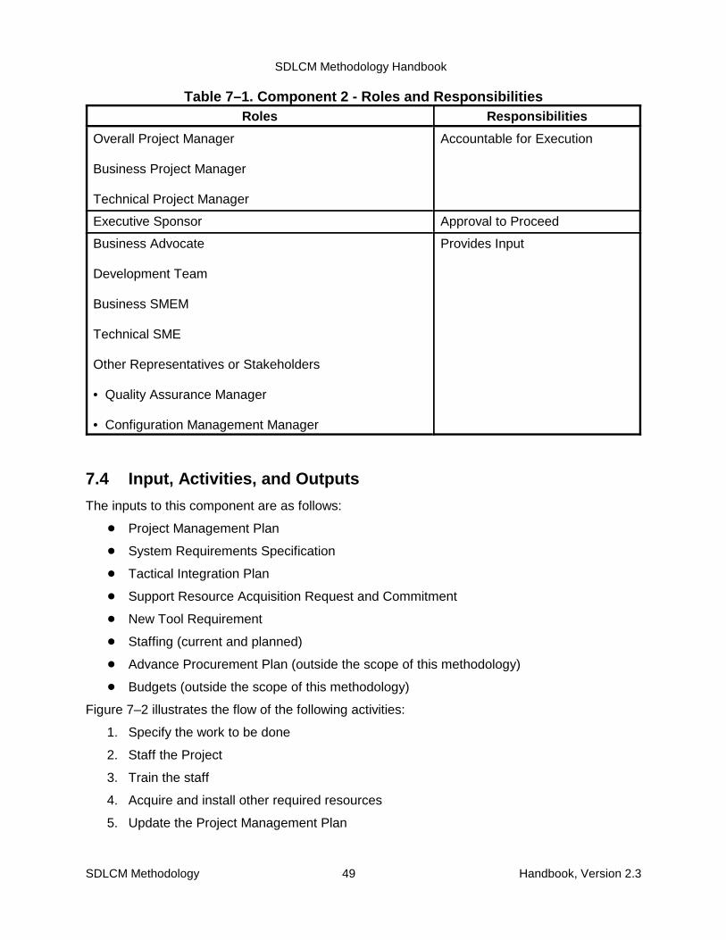
SDLCM Methodology Handbook
SDLCM Methodology 49 Handbook, Version 2.3
Table 7–1. Component 2 - Roles and ResponsibilitiesRoles Responsibilities
Overall Project Manager
Business Project Manager
Technical Project Manager
Accountable for Execution
Executive Sponsor Approval to Proceed
Business Advocate
Development Team
Business SMEM
Technical SME
Other Representatives or Stakeholders
• Quality Assurance Manager
• Configuration Management Manager
Provides Input
7.4 Input, Activities, and Outputs
The inputs to this component are as follows:
� Project Management Plan
� System Requirements Specification
� Tactical Integration Plan
� Support Resource Acquisition Request and Commitment
� New Tool Requirement
� Staffing (current and planned)
� Advance Procurement Plan (outside the scope of this methodology)
� Budgets (outside the scope of this methodology)
Figure 7–2 illustrates the flow of the following activities:
1. Specify the work to be done
2. Staff the Project
3. Train the staff
4. Acquire and install other required resources
5. Update the Project Management Plan
SDLCM Methodology Handbook
SDLCM Methodology 50 Handbook, Version 2.3
6. Continue Deployment Planning
7. Review (Component 2)
The inputs to this component were produced as products of Component 1 or prior to the start ofthe Project and are in the Project-Level CM library.
As the figure suggests, many of the activities can be performed in parallel. The activities aredescribed in more detail in Section 7.7.
Figure 7–2 also summarizes the outputs of all Component 2 activities in the central data store.
Appendix C includes a summary description of all products of NRC Projects, indicates withinwhich components each product is created and updated, and specifies which products arerequired.
The products, whose standard and form numbers are shown in the figure, are described inmore detail in the companion volume SDLCM Methodology Procedures, Standards, and Forms.
7.5 Techniques and Tools
The activities of Component 2 are supported by the following techniques.
� Structured Walkthrough
� Peer Review
Refer to the current Technical Reference Model for the recommended set of tools.
7.6 Exit Criteria
Component 2 is complete when:
� All critical products have been reviewed (structured walkthrough or peer review)
� Key products have been inspected by QA to conform to Project standards
� Products have been placed under CM control
� Information has been shared
� Issues have been resolved
� There is management buy-in to move forward
� There are no reasons to stop this Project now
7.7 Component 2 Activity Details
The following pages provide detailed activities of Component 2, Acquire Support Resources.

SDLCM Methodology Handbook
SDLCM Methodology 51 Handbook, Version 2.3
Project Management Plan, S-1052Tactical Integration Plan (TIP), S-5051Development and Maintenance Environment Products Installation Plan, S-1055Statement of Work (SOW), S-1053Support Resource Acquisition Strategy Form, F-1062Developer Training Requirements Form, F-7051Fully Staffed and Trained Team Form, F-1181Go or No Go Decision for Project Form, Component 2, F-1152
2.1 Specify theWork to be done
Skills needed
Current staffing
2.2 Staff theProject
2.3 Train theStaff
2.4 Acquire andInstall otherRequired
Resources
2.5 Update PMP
Project-Level CMLibrary fromComponent 1
Trained Staff
F-1061
PMP Updated
2.6 ContinueDeployment
Planning
TIP Updated
F-7051
2.7 Review(Go or No GoDecision forProject FormComponent 2,
F-1152)
Go No Go
Component 3Design theSolution
D&M Env Prod Installation PlanF-1062
F-1181
SOW PMP
Figure 7–2. Component 2

SDLCM Methodology Handbook
SDLCM Methodology 52 Handbook, Version 2.3
SRS
WorkBreakdownStructure
Create aWork
BreakdownStructure
Statement of WorkStandard S-1053
Staff
Create aStatement of
Work forContractors
Contractors
Statement ofWork
AlternativesAnalysis
Figure 7–3. Specify the Work to be Done
Activity 2.1: Specify the Work to Be Done
See Figure 7–3. Using the products of Component 1 as Input, prepare a statement of work andsubmit it to a contractor using a contractual funding vehicle. (As explained in Section 7.1,discussion of contracts and funding vehicles is outside the scope of the SDLCM Methodology.)
1. Create a work breakdown structure that specifies the work to be done by both NRC staffand contractors. Develop a matrix showing what work needs to be done and by whom.See Table 7–2.
2. Using the work breakdown structure, create a Statement of Work for contractedresources.
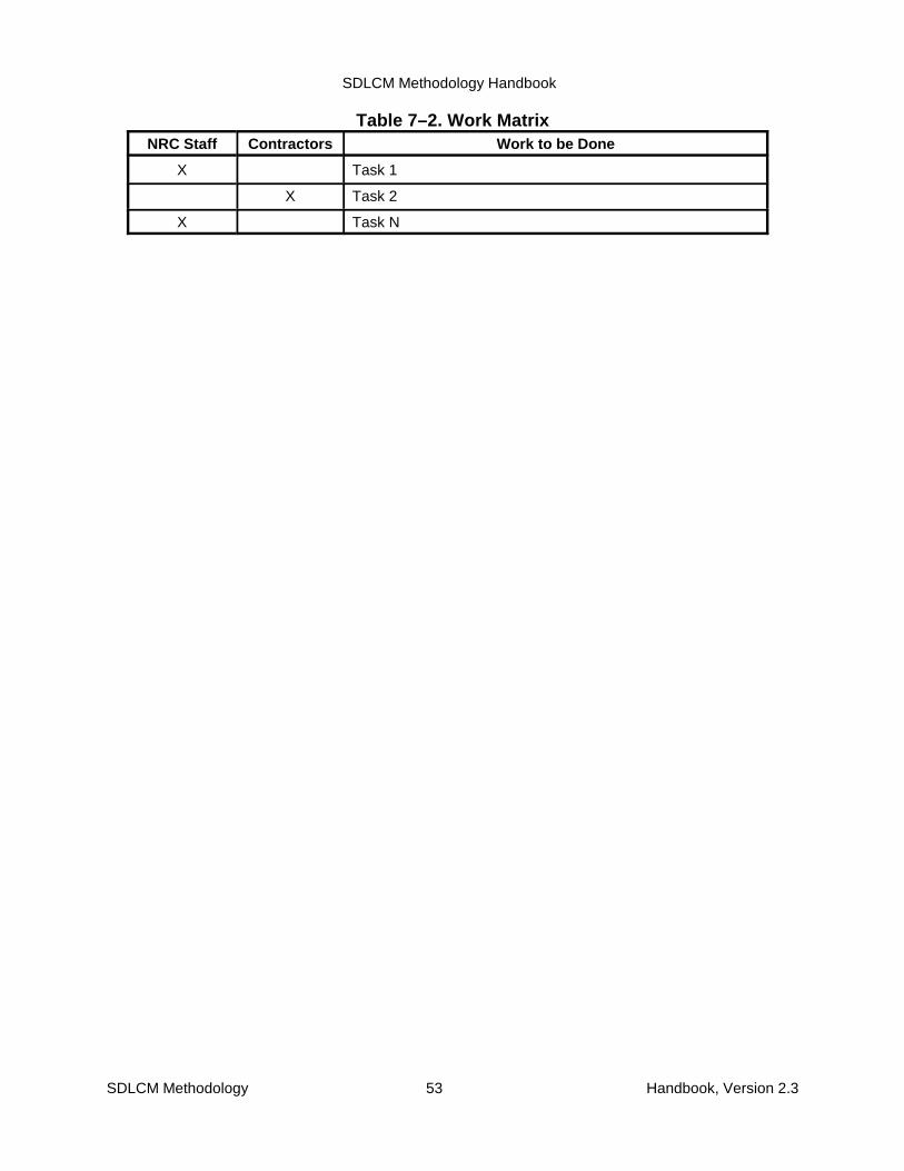
SDLCM Methodology Handbook
SDLCM Methodology 53 Handbook, Version 2.3
Table 7–2. Work MatrixNRC Staff Contractors Work to be Done
X Task 1
X Task 2
X Task N

SDLCM Methodology Handbook
SDLCM Methodology 54 Handbook, Version 2.3
Activity 2.2: Staff the Project
See Figure 7–4. Using the SRS (for an understanding of the technical skills of the peoplerequired), an awareness of the current staff, planned staff, and budget:
1. Determine any additional staffing requirements needed for the Project to be a success.
2. Acquire additional staff, using contractors as needed and budgeted for
3. Establish team rules of operation and document them in the Project Management Plan

SDLCM Methodology Handbook
SDLCM Methodology 55 Handbook, Version 2.3
StaffingNeeds
DetermineStaff
Require-ments
Acquireadditional
staff
Full Team inPlace
Establishteam Rulesof Operation
Team Rulesof Operation
CurrentStaffing
PlannedStaffing
Budget SRS PMP
PMPIncorporaterules
Figure 7–4. Staff the Project
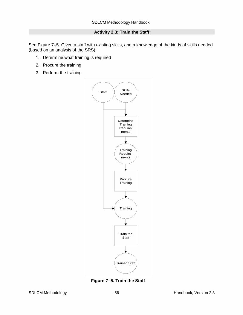
SDLCM Methodology Handbook
SDLCM Methodology 56 Handbook, Version 2.3
Staff
TrainingRequire-ments
DetermineTrainingRequire-ments
SkillsNeeded
Training
ProcureTraining
Trained Staff
Train theStaff
Figure 7–5. Train the Staff
Activity 2.3: Train the Staff
See Figure 7–5. Given a staff with existing skills, and a knowledge of the kinds of skills needed(based on an analysis of the SRS):
1. Determine what training is required
2. Procure the training
3. Perform the training

SDLCM Methodology Handbook
SDLCM Methodology 57 Handbook, Version 2.3
Activity 2.4: Acquire and Install Other Required Resources
See Figure 7–6. Using the Support Resources Acquisition Commitments obtained fromComponent 1, as well as the Advanced Procurement Plan, budget information, and ToolRequest forms:
1. Select an acquisition strategy for additional resources
2. Obtain items within budget
3. Prepare a plan to install resources needed for the development and maintenanceenvironment
4. Install the support resources
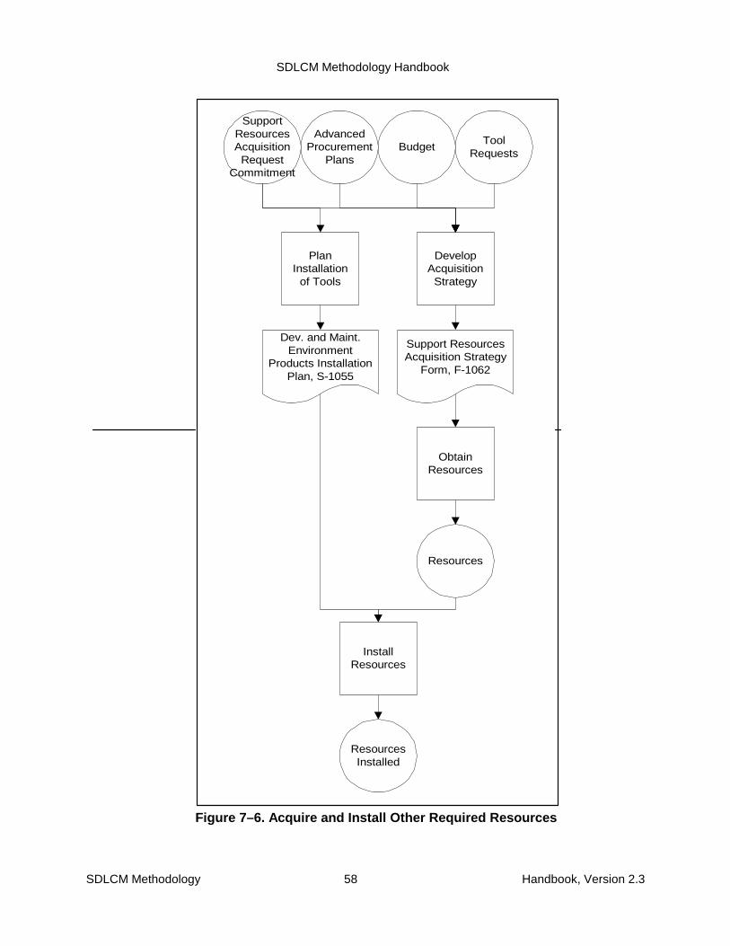
SDLCM Methodology Handbook
SDLCM Methodology 58 Handbook, Version 2.3
SupportResourcesAcquisition
RequestCommitment
DevelopAcquisition
Strategy
AdvancedProcurement
PlansBudget
ToolRequests
Resources
ObtainResources
ResourcesInstalled
InstallResources
Support ResourcesAcquisition Strategy
Form, F-1062
PlanInstallation
of Tools
Dev. and Maint.Environment
Products InstallationPlan, S-1055
Figure 7–6. Acquire and Install Other Required Resources
SDLCM Methodology Handbook
SDLCM Methodology 59 Handbook, Version 2.3
Statement ofWork
ProjectManagement
Plan
UpdateProject
ManagementPlan
InstalledResources
StaffTrainingAccom-plished
Figure 7–7. Update the Project ManagementPlan
Activity 2.5: Update the Project Management Plan
See Figure 7–7. Using the current status of the Project staff and other resources,
1. Review the Project Management Plan
2. Update the Project Management Plan so that schedules, staffing profiles, riskassessments, and any other management planning matters reflect the current status

SDLCM Methodology Handbook
SDLCM Methodology 60 Handbook, Version 2.3
TacticalIntegration
Plan
UpdateTactical
IntegrationPlan
Statement ofWork
InstalledResources
StaffTrainingAccom-plished
TIP
Figure 7–8. Continue Deployment Planning
Activity 2.6: Continue Deployment Planning
See Figure 7–8. Using the current status of the Project,
1. Review the Tactical Integration Plan
2. Update the Tactical Integration Plan so that deployment schedules and any otherdeployment matters reflect the current status

SDLCM Methodology Handbook
SDLCM Methodology 61 Handbook, Version 2.3
Statement ofWork
Go or No-GoDecision For Project
Form, F-1152
InstalledResources
StaffTrainingAccom-plished
Review
Figure 7–9. Review Component 2
Activity 2.7: Review (Component 2)
See Figure 7–9. Review the Project to make a GO or NO-GO decision.
1. Review for the need for the Project and the Project status
� Has the work been specified?
� Are all equipment resources operational before we move forward with the Project?
� Is the Project team in place?
� Is the team trained and ready to begin work?
� Is there sufficient organizational commitment and executive sponsorship to moveforward with the Project?
2. Complete the form required to obtain approval to proceed.
SDLCM Methodology Handbook
SDLCM Methodology 62 Handbook, Version 2.3
8. Component 3. Design the Solution8.1 Purpose
The purpose of this component is to:
� Determine functional requirements
� Determine data requirements
� Determine communication requirements
� Determine network requirements
� Document user interface requirements
� Design the solution
� Prepare integration plans
� Prepare Project plans
� Prepare training plans and define operational training materials
� Secure a Go Decision to proceed with engineering the solution
8.2 Roles and Responsibilities
The roles required to perform the activities in the Design the Solution component are shown inTable 8–1.
Table 8–1. Component 3 Roles and ResponsibilitiesRoles Responsibilities
Overall Project Manager
Business Project Manager
Technical Project Manager
Development Team
Accountable for Execution
Executive Sponsor
Business Advocate
Approval to Proceed
Business Advocate
Business SME
Technical SME
Other Representatives or Stakeholders
• Quality Assurance Manager• Configuration Management Manager
Provides Input
SDLCM Methodology Handbook
SDLCM Methodology 63 Handbook, Version 2.3
8.3 Entry Criteria
The Following events may trigger the initiation of Component 3:
� Completion of Component 2, Acquire Support Resources
� Receipt of additional requirements
8.4 Input, Activities and Outputs
The inputs to this component are as follows:
� Project Management Plan
� Configuration Management Plan
� Quality Assurance Plan
� System Operations Concept
� Current System Assessment Document
� Alternatives Analysis Document
� System Requirements Specification
� Tactical Integration Plan
� Fully Staffed and trained Project team
� Installed resources for design
� Infrastructure
� Selected technology and tools
� Budget allocation
� Enterprise Model
� Technical Reference Model
Figure 8–1 illustrates the flow of the following activities:
1. Analyze Requirements and Perform High Level Design
2. Plan Solution Integration
3. Design Training Materials
4. Establish Test Approach
5. Update Project Management Plan and Software Development Plan
6. Continue Deployment Planning
7. Review (Component 3)

SDLCM Methodology Handbook
SDLCM Methodology 64 Handbook, Version 2.3
Project Management Plan (PMP), S-1052Software Development Plan (SDP), S-1057System Requirements Specification (SRS), S-3051System Operations Concept (SOC), S-3053Logical Design Document (LDD), S-3171/Physical Design Document (PDD), S-3172
Data Models (DM), S-3151Process Models (PM), S-3161Context Diagrams (CD), S-3162Data Flow Diagrams (DFD), S-3163Data Dictionary (DD), S-3351
Tactical Integration Plan (TIP) , S-5051Products Installation and Integration Plan, S-5052Other Integration Issues Plan, S-5055Solution Integration Plan, S-5053Other Systems Integration Plan, S-5054External System Interface Diagram, S-3164Security Controls, S-1056Conversion Plan, S-1054
Test Plan, S-5151Integrated Education, Training, and Reference Materials, S-7052Software Engineering Notebook, S-3091Enterprise Model Change Request Form, F-2070Technical Reference Model Update Form, F-2073Go or No Go Decision for Project Form, F-1153
3.1 AnalyzeRequirements
and Perform HighLevel Design
SRSSOCLDDPDDSENF-2070
3.2 Plan SolutionIntegration
3.3 DesignTrainingMaterials 3.4 Establish
Test Approach
3.6 ContinueDeployment
Planning
3.7 Review (Go or No GoDecision forProject Form
Component 3,F-1153)
Component 4Engineer the
Solution
Project Library fromprevious Components
Training Materials Test Plan
SRS
PMPSDP
TIPF-2073 Go No Go
TIP(Solution Integration Plan)
3.5 Update PMPand SDP
When the LDD and/or PDD arereferenced, they include referencesto the DM, PM, CD, DFD, and DD.
Figure 8–1. Component 3

SDLCM Methodology Handbook
SDLCM Methodology 65 Handbook, Version 2.3
The inputs to this component were produced as products of earlier components. As Figure 8–1suggests, many of the activities can be performed in parallel. Figure 8–1 also summarizes theoutputs of all Component 3 activities in the central data store. The activities are described inmore detail in Section 8.7.
When the Logical Design Document and/or Physical Design Document are referenced in thisHandbook, they include references to the Data Models (DM), Process Models (PM), ContextDiagrams (CD), Data Flow Diagrams (DFD), and Data Dictionary (DD).
Appendix C includes a summary description of all products of NRC Projects, indicates withinwhich components each product is created and updated, and specifies which products arerequired.
The products, whose standard and form numbers are shown in the figure, are described inmore detail in the companion volume SDLCM Methodology Procedures, Standards, and Forms.
8.5 Techniques and Tools
The activities of Component 3 are supported by the following techniques.
� Data Modeling
� Joint Application Design and Development
� Process Modeling
� Prototyping
� Structured Facilitation
� Structured Walkthrough
� Peer Review
Refer to the current SDLCM Methodology Tool Inventory for the recommended set of tools.
8.6 Exit Criteria
Component 3 is complete when:
� All critical products have been reviewed (structured walkthrough or peer review).
� Key products have been inspected by QA to conform to Project standards.
� Products have been placed under CM control.
� Information has been shared.
� Issues have been resolved.
� There is management buy-in to move forward.
� There are no reasons to stop this Project now.
8.7 Component 3 Activity Details
The following pages provide detailed activities of Component 3, Design the Solution.
SDLCM Methodology Handbook
SDLCM Methodology 66 Handbook, Version 2.3
Activity 3.1: Analyze Requirements and Perform High Level Design
This activity is divided into six sub-activities described on the following pages:
3.1.1 Analyze Network
3.1.2 Analyze Data
3.1.3 Analyze and Design Processes
3.1.4 Analyze and Design User Interface
3.1.5 Analyze Platform and Operation System
3.1.6 Design for Functional Requirements
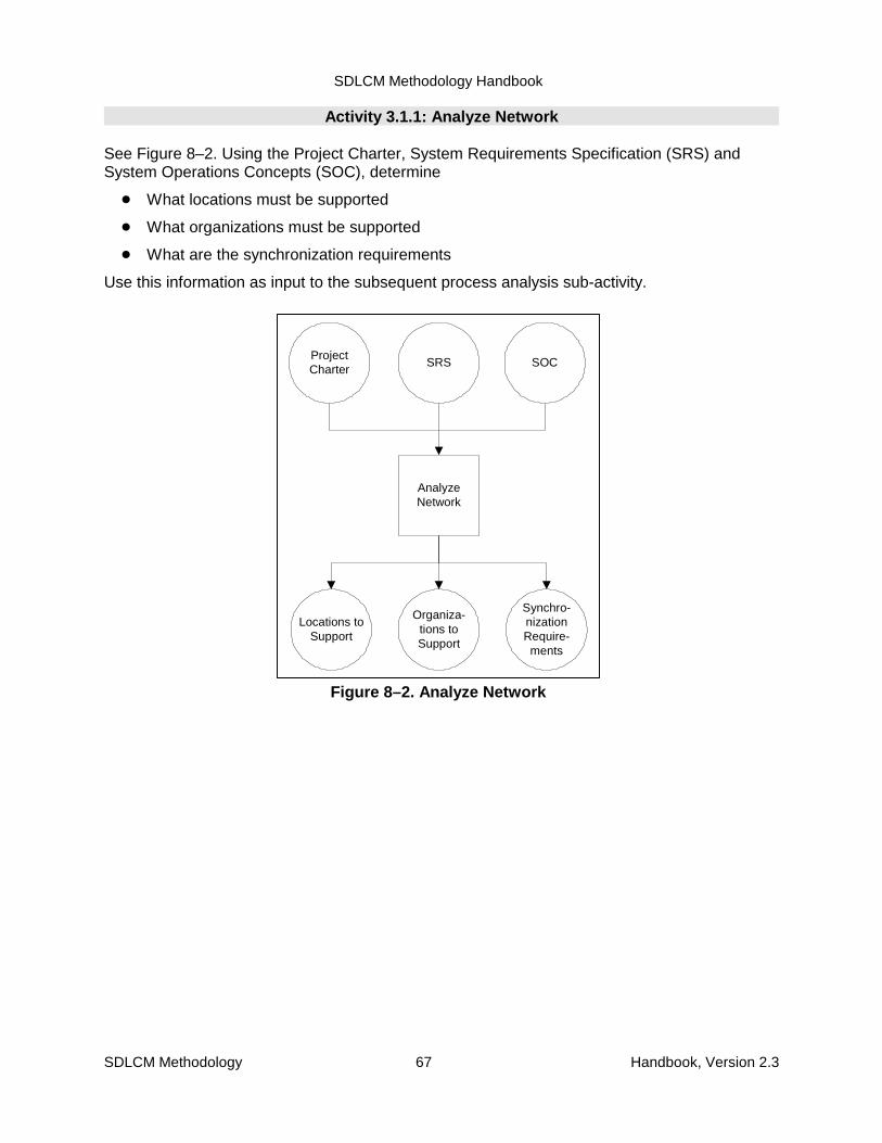
SDLCM Methodology Handbook
SDLCM Methodology 67 Handbook, Version 2.3
SRS
Locations toSupport
AnalyzeNetwork
ProjectCharter
Organiza-tions toSupport
Synchro-nizationRequire-ments
SOC
Figure 8–2. Analyze Network
Activity 3.1.1: Analyze Network
See Figure 8–2. Using the Project Charter, System Requirements Specification (SRS) andSystem Operations Concepts (SOC), determine
� What locations must be supported
� What organizations must be supported
� What are the synchronization requirements
Use this information as input to the subsequent process analysis sub-activity.
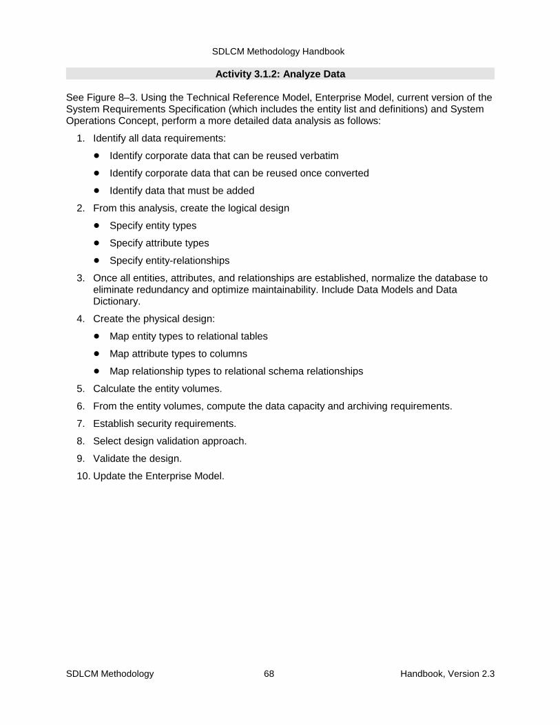
SDLCM Methodology Handbook
SDLCM Methodology 68 Handbook, Version 2.3
Activity 3.1.2: Analyze Data
See Figure 8–3. Using the Technical Reference Model, Enterprise Model, current version of theSystem Requirements Specification (which includes the entity list and definitions) and SystemOperations Concept, perform a more detailed data analysis as follows:
1. Identify all data requirements:
� Identify corporate data that can be reused verbatim
� Identify corporate data that can be reused once converted
� Identify data that must be added
2. From this analysis, create the logical design
� Specify entity types
� Specify attribute types
� Specify entity-relationships
3. Once all entities, attributes, and relationships are established, normalize the database toeliminate redundancy and optimize maintainability. Include Data Models and DataDictionary.
4. Create the physical design:
� Map entity types to relational tables
� Map attribute types to columns
� Map relationship types to relational schema relationships
5. Calculate the entity volumes.
6. From the entity volumes, compute the data capacity and archiving requirements.
7. Establish security requirements.
8. Select design validation approach.
9. Validate the design.
10. Update the Enterprise Model.
SDLCM Methodology Handbook
SDLCM Methodology 69 Handbook, Version 2.3
TechnicalReference
Model
EnterpriseModel
1. Identify alldata require-
ments
CorporateData to beConverted
Data to beAdded
VerbatimCorporate
Data
2. CreateLogicalDesign
AttributeTypes
EntityRelation-
shipsEntity Types
InformationTypes
3. Normalizethe
Database
NormalizedDatabase
(3NF)
4. CreatePhysicalDesign
ColumnsRelationalSchemas
RelationalTables
Data Types
5. ComputeEntity
Volumnes
EntityVolumes
6. ComputeData Cap. &
andArchiving
Req’s
DataCapacity
ArchivingRequire-
ments
7. EstablishSecurityRequire-
ments
Securityrequire-ments
8. SelectDesign
ValidationApproach
DesignValidationApproach
9. ValidateDesign
ValidatedDesign
10. UpdateEnterprise
Model
UpdatedEnterprise
Model
SRS SOC
Logical DesignDocumentStandardS-3171
Physical DesignDocumentStandardS-3172
AAD CSAD
Figure 8–3. Analyze Data

SDLCM Methodology Handbook
SDLCM Methodology 70 Handbook, Version 2.3
Activity 3.1.3 Analyze and Design Processes
See Figure 8–4. Using the System Operations Concept and the results of the previous DataAnalysis sub-activity, analyze the processes required for the information management systemand identify what processes should be automated and which ones should be manual.Document the results of the analysis and design in the logical and physical design documents.Specifically:
1. Identify business procedures, practices, and decision-making activities that must be apart of the information management system. Include the records managementrequirements of the business.
2. Identify security requirements.
3. Identify external events.
4. Merge the business procedures, security requirements, and external events with thesoftware and hardware part of the information management system to create a data flowdiagram. Update Context Diagrams and Data Flow Diagrams, as appropriate.
5. Identify complex processes that must be decomposed and modeled. Create ProcessModels.
6. Decompose and model complex processes.
7. From the processes, determine which processes should be manual and which should beautomated.
8. Establish performance requirements by type of transaction (volume, speed, frequency,etc.)
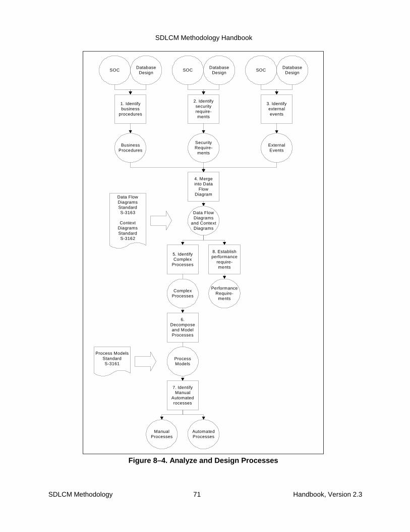
SDLCM Methodology Handbook
SDLCM Methodology 71 Handbook, Version 2.3
SOC
BusinessProcedures
1. Identifybusiness
procedures
DatabaseDesign
SecurityRequire-
ments
2. Identifysecurityrequire-ments
ExternalEvents
3. Identifyexternalevents
4. Mergeinto Data
FlowDiagram
SOCDatabase
DesignSOC
DatabaseDesign
Data FlowDiagrams
and ContextDiagrams
5. IdentifyComplex
Processes
ComplexProcesses
6.Decomposeand ModelProcesses
ProcessModels
7. IdentifyManual
Automatedrocesses
ManualProcesses
AutomatedProcesses
8. Establishperformance
require-ments
PerformanceRequire-
ments
Data FlowDiagramsStandardS-3163
ContextDiagramsStandardS-3162
Process ModelsStandardS-3161
Figure 8–4. Analyze and Design Processes

SDLCM Methodology Handbook
SDLCM Methodology 72 Handbook, Version 2.3
Activity 3.1.4: Analyze and Design User Interface
See Figure 8–5. Using the results of the database design and process design from previoussub-activities, design the user interface as follows:
1. Determine data entry requirements
2. Determine display requirements
3. Determine dialog requirements
4. Determine screen requirements
5. Create screen prototypes
6. Establish performance requirements
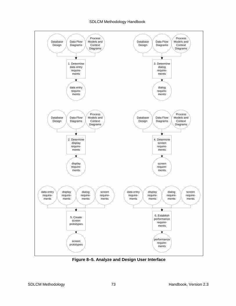
SDLCM Methodology Handbook
SDLCM Methodology 73 Handbook, Version 2.3
Data FlowDiagrams
data entryrequire-ments
1. Determinedata entryrequire-ments
DatabaseDesign
ProcessModels and
ContextDiagrams
Data FlowDiagrams
displayrequire-ments
2. Determinedisplayrequire-ments
DatabaseDesign
ProcessModels and
ContextDiagrams
Data FlowDiagrams
screenrequire-ments
4. Determinescreenrequire-ments
DatabaseDesign
ProcessModels and
ContextDiagrams
Data FlowDiagrams
dialogrequire-ments
3. Determinedialog
require-ments
DatabaseDesign
ProcessModels and
ContextDiagrams
displayrequire-ments
screenprototypes
5. Createscreen
prototypes
data entryrequire-ments
dialogrequire-ments
screenrequire-ments
displayrequire-ments
performancerequire-ments
6. Establishperformance
require-ments
data entryrequire-ments
dialogrequire-ments
screenrequire-ments
Figure 8–5. Analyze and Design User Interface
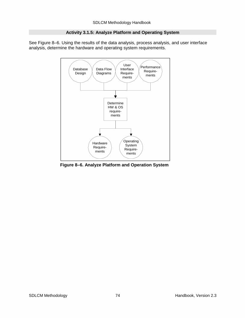
SDLCM Methodology Handbook
SDLCM Methodology 74 Handbook, Version 2.3
Data FlowDiagrams
HardwareRequire-ments
DetermineHW & OSrequire-ments
DatabaseDesign
UserInterfaceRequire-ments
PerformanceRequire-ments
OperatingSystemRequire-ments
Figure 8–6. Analyze Platform and Operation System
Activity 3.1.5: Analyze Platform and Operating System
See Figure 8–6. Using the results of the data analysis, process analysis, and user interfaceanalysis, determine the hardware and operating system requirements.
SDLCM Methodology Handbook
SDLCM Methodology 75 Handbook, Version 2.3
Activity 3.1.6: Design for Functional Requirements
See Figure 8–7. Using the results of the:
� Data analysis and database design
� Process analysis and design
� User interface analysis and design
� Hardware and operating system analysis
Design any additional functions required to create an information management system that:
� Reuses corporate databases
� Converts corporate data as required
� Provides support for automating processes appropriately
� Supports the user interfaces as designed above
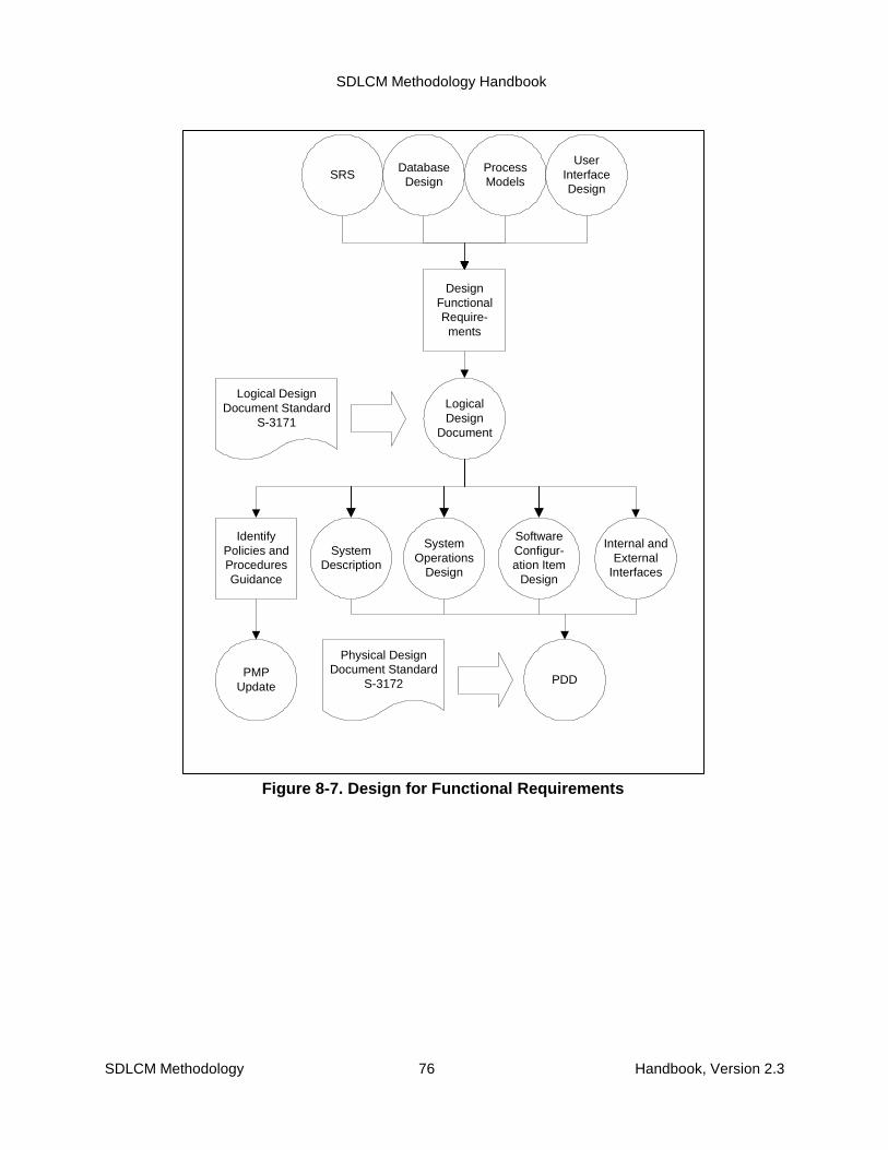
SDLCM Methodology Handbook
SDLCM Methodology 76 Handbook, Version 2.3
ProcessModels
LogicalDesign
Document
DesignFunctionalRequire-
ments
Logical DesignDocument Standard
S-3171
SRSDatabase
Design
UserInterfaceDesign
SystemDescription
SystemOperations
Design
SoftwareConfigur-ation Item
Design
Internal andExternal
Interfaces
PMPUpdate
PDD
Physical DesignDocument Standard
S-3172
IdentifyPolicies andProceduresGuidance
Figure 8-7. Design for Functional Requirements

SDLCM Methodology Handbook
SDLCM Methodology 77 Handbook, Version 2.3
DatabaseDesign
SolutionIntegration
P lan
DevelopSolution
IntegrationP lan
PeerReview
PeerReviewed
Output
QAInspec-
tion
QAInspected
Output
Pro ject-Level CMCaptureProcess
Solution In tegrationP lan Standard
S-5053(or TIP , S-5151)
Pro ject-LevelCM Library
ProcedureP-2101 Com ments
Quality AssuranceStandardS-2001
QACom ments
Pro ject-Level CMProcedures
OperatingSystem
Require-m ents
HardwareRequire-
m ents
Functiona lDesign
UserInterfaceDesign
Autom atedProcesses
Figure 8–8. Plan Solution Integration
Activity 3.2: Plan Solution Integration
See Figure 8–8. Using the results of Activity 3.1, develop a plan for integrating the solution.

SDLCM Methodology Handbook
SDLCM Methodology 78 Handbook, Version 2.3
Activity 3.3: Design Training Materials
See Figure 8–9. Using the system requirements and the results of requirements analysis andhigh level design, design the training materials.
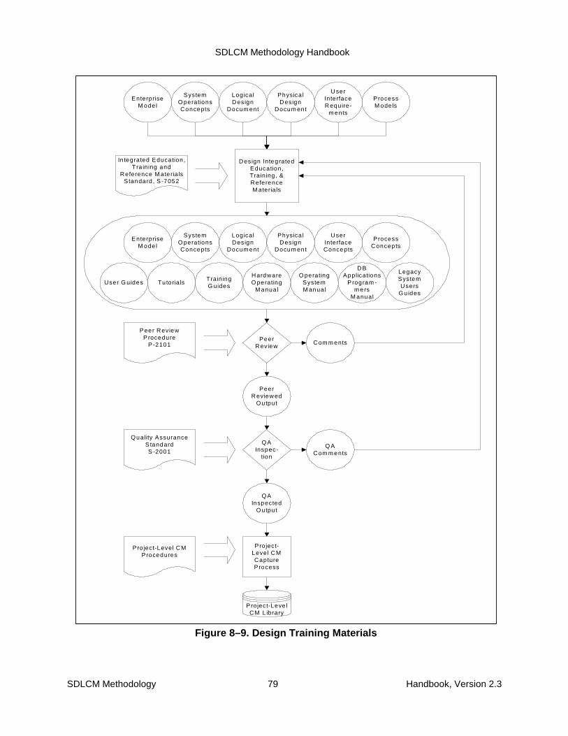
SDLCM Methodology Handbook
SDLCM Methodology 79 Handbook, Version 2.3
SystemO perationsConcepts
Design IntegratedEducation,Training , &ReferenceM aterials
PeerReview
PeerReviewed
Output
QAInspec-
tion
QAInspected
Output
P roject-Leve l CMCaptureProcess
Project-Leve lCM L ibrary
Peer ReviewProcedure
P -2101 Com m ents
Quality AssuranceS tandardS -2001
Q ACom m ents
Pro ject-Level CMProcedures
In tegrated Education ,Tra ining and
Reference M ateria lsStandard , S -7052
EnterpriseM odel
Log icalDesign
Docum ent
Physica lDesign
Docum ent
UserInterfaceRequire-
m ents
ProcessM odels
Tutoria lsUser G uidesTrainingG uides
HardwareO perating
M anual
O peratingSystemM anual
DBApplications
P rogram -m ers
M anual
LegacySystemUsers
Guides
SystemO perationsConcepts
EnterpriseM odel
Log icalDesign
Docum ent
Physica lDesign
Docum ent
UserInterfaceConcepts
ProcessConcepts
Figure 8–9. Design Training Materials
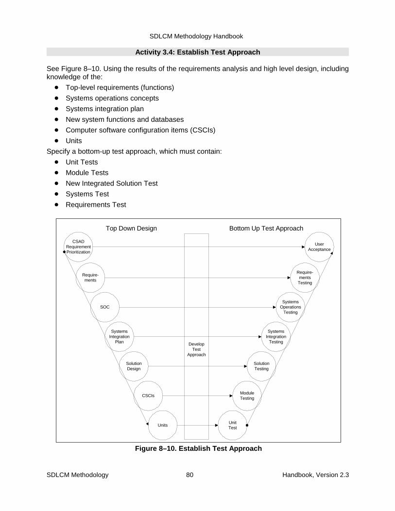
SDLCM Methodology Handbook
SDLCM Methodology 80 Handbook, Version 2.3
SystemsIntegration
Plan DevelopTest
Approach
SOC
Require-ments
Units
SolutionDesign
CSCIs
Top Down Design Bottom Up Test Approach
SystemsIntegration
Testing
SystemsOperations
Testing
Require-ments
Testing
UnitTest
SolutionTesting
ModuleTesting
CSADRequirementPrioritization
UserAcceptance
Figure 8–10. Establish Test Approach
Activity 3.4: Establish Test Approach
See Figure 8–10. Using the results of the requirements analysis and high level design, includingknowledge of the:
� Top-level requirements (functions)
� Systems operations concepts
� Systems integration plan
� New system functions and databases
� Computer software configuration items (CSCIs)
� Units
Specify a bottom-up test approach, which must contain:
� Unit Tests
� Module Tests
� New Integrated Solution Test
� Systems Test
� Requirements Test
SDLCM Methodology Handbook
SDLCM Methodology 81 Handbook, Version 2.3
Activity 3.5: Update Project Management Plan
See Figure 8–11. Using the work results, identify any changes required in the resources,schedules, and activities. Update the Project Management Plan.
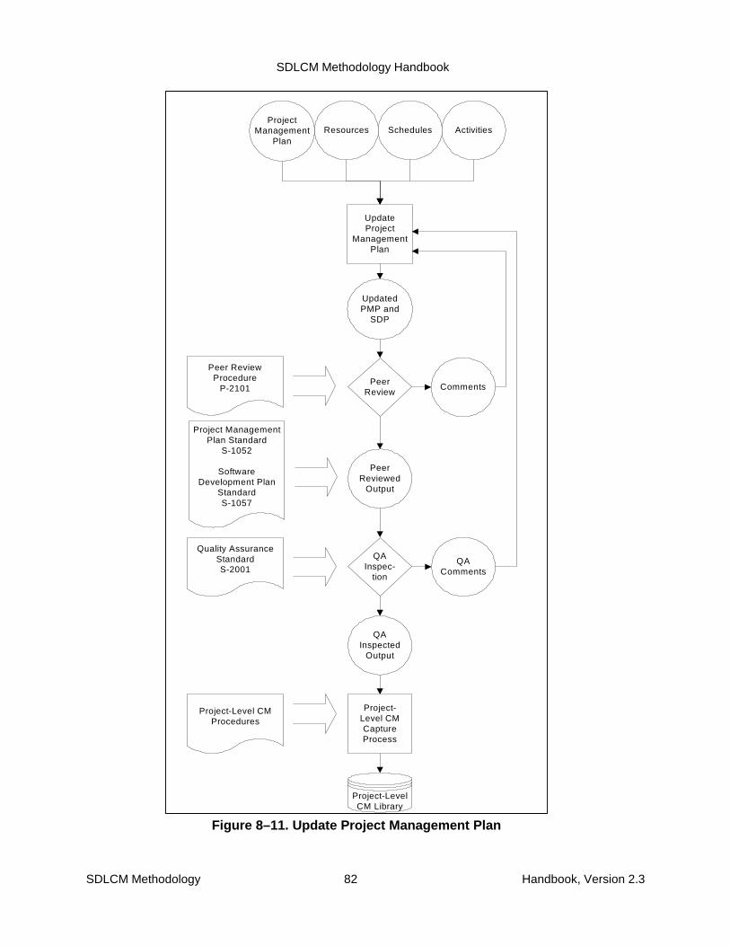
SDLCM Methodology Handbook
SDLCM Methodology 82 Handbook, Version 2.3
Resources
UpdatedPMP and
SDP
UpdateProject
ManagementPlan
PeerReview
PeerReviewed
Output
QAInspec-
tion
QAInspected
Output
Project-Level CMCaptureProcess
Project ManagementPlan Standard
S-1052
SoftwareDevelopment Plan
StandardS-1057
Project-LevelCM Library
Peer ReviewProcedure
P-2101 Comments
Quality AssuranceStandardS-2001
QAComments
Project-Level CMProcedures
Schedules ActivitiesProject
ManagementPlan
Figure 8–11. Update Project Management Plan

SDLCM Methodology Handbook
SDLCM Methodology 83 Handbook, Version 2.3
Activity 3.6: Continue Deployment Planning
See Figure 8–12. Using the Solution Integration Plan, and the results of the network analysis,analysis of other systems that can be reused verbatim, analysis of other systems that can bereused in part by establishing conversion requirements, establish a system integration plan.
1. Identify other systems for integration
2. Identify systems security requirements
3. Update the other portions of the TIP or development separate sub-plans
4. Update Technical Reference Model

SDLCM Methodology Handbook
SDLCM Methodology 84 Handbook, Version 2.3
OtherSystems tobe Reused
3. DevelopSolution
IntegrationPlan
NetworkRequire-ments
SolutionIntegration
Plan
ConversionRequire-ments
SecurityRequire-ments
AutomatedProcesses
1. IdentifyOther
Systems forIntegration
2. IdentifySystemSecurityRequire-ments
SystemsIntegration
Plan
InstallationRequire-
ments
4. UpdateTechnicalReference
Model
TechnicalReference
Model
Solution IntegrationPlan Standard
S-5053
Figure 8–12. Continue Deployment Planning
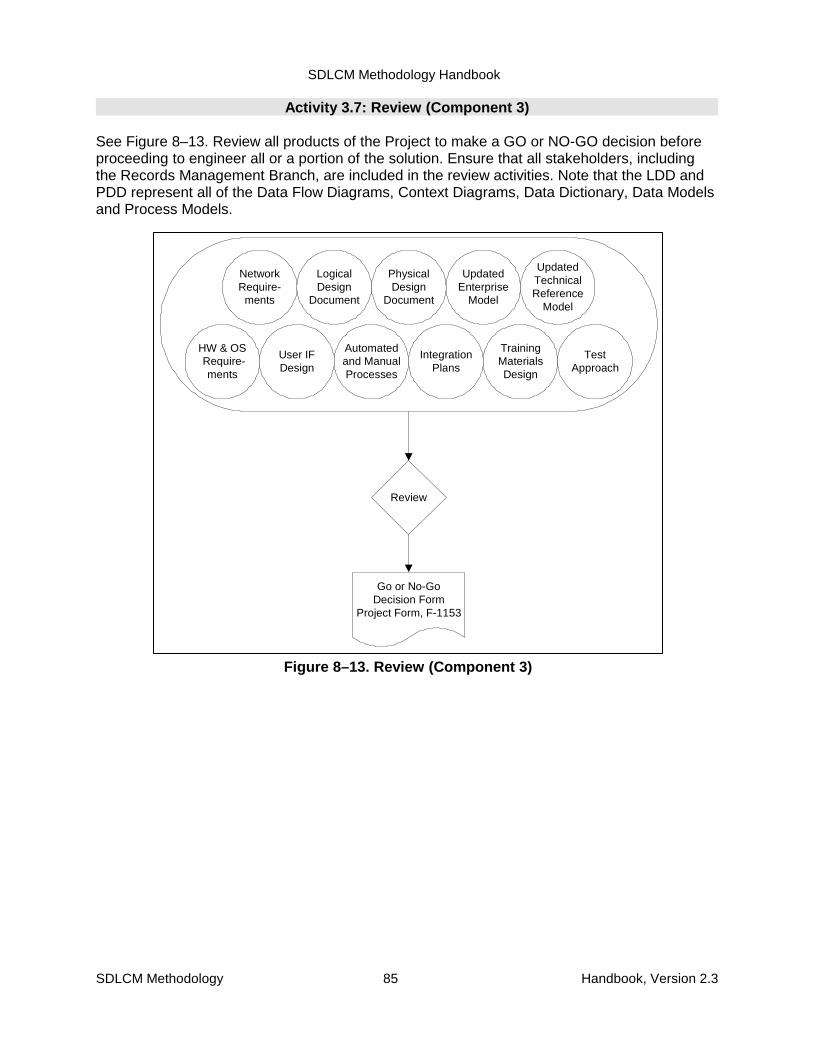
SDLCM Methodology Handbook
SDLCM Methodology 85 Handbook, Version 2.3
PhysicalDesign
Document
LogicalDesign
Document
User IFDesign
Review
Go or No-GoDecision Form
Project Form, F-1153
IntegrationPlans
TrainingMaterialsDesign
Automatedand ManualProcesses
TestApproach
NetworkRequire-
ments
UpdatedEnterprise
Model
UpdatedTechnicalReference
Model
HW & OS Require-
ments
Figure 8–13. Review (Component 3)
Activity 3.7: Review (Component 3)
See Figure 8–13. Review all products of the Project to make a GO or NO-GO decision beforeproceeding to engineer all or a portion of the solution. Ensure that all stakeholders, includingthe Records Management Branch, are included in the review activities. Note that the LDD andPDD represent all of the Data Flow Diagrams, Context Diagrams, Data Dictionary, Data Modelsand Process Models.
SDLCM Methodology Handbook
SDLCM Methodology 86 Handbook, Version 2.3
9. Component 4. Engineer the Solution9.1 Purpose
The purpose of this component is to build the application system, which includes the following:
� Maintain the Change Log
� Validate/Refine Design
� Select an engineering approach
� Construct or acquire all modules of the system
� Unit Test
� Integrate the solution
� System test the solution
� Create the rollout strategy and continue planning for deployment
� Assess and update agency policies and procedures
� Construct the policy and procedures that support the system and the required trainingand education materials
� Update the Project Management Plan
� Secure a Go decision to move to pre-deployment testing
9.2 Roles and Responsibilities
The roles required to perform the activities in the Engineer the Solution component are shownin Table 9–1.
Table 9–1. Component 4 Roles and ResponsibilitiesRoles Responsibilities
Overall Project Manager
Technical Project Manager
Technical SME for Infrastructure
Development Team
Accountable for Execution ofActivities
Executive Sponsor
Business Advocate
Business Project Manager
Business SME
Other Technical SMEs
Provides Input

SDLCM Methodology Handbook
SDLCM Methodology 87 Handbook, Version 2.3
9.3 Entry Criteria
The following event may trigger the initiation of Component 4:
� Some portion of the solution design approved for engineering
9.4 Input, Activities, and Outputs
The inputs to this component are as follows:
� Updated Project Management Plan
� Updated Systems Requirements Specification
� Logical Design Document
� Physical Design Document
� Updated Tactical Integration Plan, including
� Products Installation and Integration Plan
� Other Integration Issues Plan
� Solution Integration Plan
� Other Systems Integration Plan
� Security Plan
� Conversion Plan
� Test Plan
� Integrated Education, Training, and Reference Materials
� Software Engineering Notebook
� Change Requests, if any
The inputs to this component were produced as products of earlier components.
Figure 9–1 illustrates the flow of the following activities:
1. Maintain the Change Log
2. Engineer the Detailed Design
3. Build the Solution
4. Integrate the Solution
5. Test the Solution
6. Create the Rollout Strategy and Continue Deployment Planning
7. Update Policies and Procedures
8. Build the User Material and Training Materials
9. Deliver Training
10. Update the Project Management Plan and Software Development Plan
11. Review (Component 4) and Transfer Materials to Central Configuration Management

SDLCM Methodology Handbook
SDLCM Methodology 88 Handbook, Version 2.3
Project Management Plan (PMP), S-1052 Operational Support Guide, S-6151Software Development Plan (SDP), S-1057 User Training and Orientation Plan, S-7053Software Engineering Notebook (SEN), S-3091 User Guide, S-6051Alternatives Analysis Document (AAD), S-3054 Online Help Systems and Tutorials, S-6052System Operation Concept (SOC), S-3053 External Systems Interface Diagrams, S-3164Systems Requirements Specification, S-3051 Target Users Capability Upgrade Request Form, F-6054Logical Design Document, S-3171 System Inventory Update Form, F-2071Physical Design Document, S-3172 Technical Reference Model Update Form, F-2073Tactical Integration Plan (TIP) , S-5051 GILS Update Form, F-3060
Network Integration Diagrams, S-5056 Change Log Form, F-2561Other Integration Issues Plan, S-5055 Change Proposal Form, F-2502Other Systems Integration Plan, S-5054 Installation Instructions, S-5252Conversion Plan, S-1054 Go or No-Go Decision for Project, Component 4, F-1154Security Controls, S-1056Solution Integration Plan, S-5053
Test Plan, S-5151
4.1 Maintain theChange Log
(P-2501)
4.2 Engineer thedetailed design
PMPSOCSRSAADLDDPDD
4.3 Build theSolution
SEN
4.4 Integrate theSolution
4.5 Test theSolution
4.6 Create theRollout Strategyand ContinueDeployment
Planning4.11 Review(Go or No GoDecision for
Project Form,Component 4
F-1154)
Component 5Deploy theSolution
Project Library fromprevious Components
4.7 UpdatePolicies andProcedures
F-2071F-2073F-3060
4.10 Update thePMP and SDP
PMPSDP
Go No Go
DetailedDesign
SolutionModules
Integrated Solution
TIP(Installation Instructions)
(Network Diagram)F-6054F-4051SEN
F-2561F-2502
F-2561F-2502
Test Plan(System Test Results)
F-4051
4.8 Build theUser Manual and
TrainingMaterials
4.9 Deliver theTraining
On-line Help System and TutorialsUser Guide
User Training and Orientation PlanOperational Support Guide
On-line Help System and TutorialsUser Guide
User Training and Orientation PlanOperational Support Guide
Figure 9–1. Component 4

SDLCM Methodology Handbook
SDLCM Methodology 89 Handbook, Version 2.3
As the figure suggests, some of the activities can be performed in parallel. However, wheredecisions or data must be presented from one activity to another, the activities must beperformed sequentially (i.e., 4.1 through 4.5, 4.6 and 4.8, 4.7 is dependent upon 4.5 and 4.6 forinput.). The activities are described in more detail in Section 9.7.
Figure 9–1 also summarizes the outputs of all Component 4 activities in the central data store.
Appendix C includes a summary description of all products of NRC projects, indicates withinwhich components each product is created and updated, and specifies which products arerequired.
The products, whose standard and form numbers are shown in the figure, are described inmore detail in the companion volume SDLCM Methodology Procedures, Standards, and Forms.
9.5 Techniques and Tools
The activities of Component 4 are supported by the following techniques:
� Joint Application Design and Development
� Rapid Application Design
� Structured Facilitation
� Structured Walkthrough
� Peer Review
Refer to the current Technical Reference Model, which should have been decided inComponent 2.
9.6 Exit Criteria
Component 4 Is complete when:
� All critical software products have been reviewed (structured walkthrough or peer review)
� All critical procedures, guidelines, etc. reflecting changes to business approach and ruleshave been circulated for comment and concurrence has been received.
� Key products have been inspected by QA to conform to project standards
� Products have been placed under CM control
� Information has been shared
� Issues have been resolved
� There is management buy-in to move forward
� There are no reasons to stop this project now
9.7 Component 4 Activity Details
The following pages provide detailed activities of Component 4, Engineer the Solution.
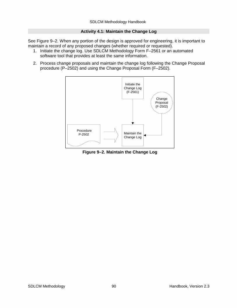
SDLCM Methodology Handbook
SDLCM Methodology 90 Handbook, Version 2.3
ChangeProposal(F-2502)
Initiate theChange Log
(F-2561)
ProcedureP-2502 Maintain the
Change Log
Figure 9–2. Maintain the Change Log
Activity 4.1: Maintain the Change Log
See Figure 9–2. When any portion of the design is approved for engineering, it is important tomaintain a record of any proposed changes (whether required or requested).
1. Initiate the change log. Use SDLCM Methodology Form F–2561 or an automatedsoftware tool that provides at least the same information.
2. Process change proposals and maintain the change log following the Change Proposalprocedure (P–2502) and using the Change Proposal Form (F–2502).

SDLCM Methodology Handbook
SDLCM Methodology 91 Handbook, Version 2.3
Activity 4.2: Engineer the Detailed Design
See Figure 9–3. Given the scope of the work to be done as documented in the SRS, designdocuments, Project Charter, the previous analysis of alternatives, and final System OperationsConcept, select an engineering approach that both maximizes reuse and the probability ofsuccess.
Perform the following sub-activities:
1. Determine if there is an off-the-shelf solution that can be directly installed
2. If not, determine if there is an off-the-shelf solution that can be modified and installed.
3. If not, plan to develop the system from scratch.
4. Using a top-down approach, partition the system into modules, specifying which partscan be reused or modified or built from scratch.
5. Review the life-cycle approach selected and schedule the development and integration ofthe modules and document this in the Project Management Plan and SoftwareDevelopment Plan.

SDLCM Methodology Handbook
SDLCM Methodology 92 Handbook, Version 2.3
Reuse,Modification,New CodeStrategy
ReviewReuse vs.
ModificationPossibilities
SRSProjectCharter
LogicalDesign
PhysicalDesign
Analysis ofAlternatives
COTSSystems
SystemArchitecture
PartitionSystem into
Modules
ProjectManagement
Plan
Life CycleApproach
UpdateSchedules,Resources,Deliverables
UpdatedSRS
UpdatedPMP
UpdatedLDD and
PDD
SoftwareDevelopment
Plan
UpdatedSDP
UpdatedSOC
UpdatedAAD
Figure 9–3. Engineer the Detailed Design
SDLCM Methodology Handbook
SDLCM Methodology 93 Handbook, Version 2.3
Activity 4.3: Build the Solution
See Figure 9–4, Using the design materials produced as a part of Component 3 and earlieractivities within Component 4:
1. Build database structure and populate the database
2. Develop program code
3. Develop external systems interfaces and update design and integration documentation,as required.

SDLCM Methodology Handbook
SDLCM Methodology 94 Handbook, Version 2.3
LogicalDesign
Document
PhysicalDatabase
DevelopDatabase
PhysicalDesign
Document
DataDictionary
LogicalDesign
Document
FunctionalUnits
DevelopFunctional
Code
PhysicalDesign
Document
PhysicalDatabase
DataDictionary
LogicalDesign
Document
ExternalInterfaces
DevelopExternal
Interfaces
PhysicalDesign
Document
PhysicalDatabase
DataDictionary
FunctionalUnits
Figure 9–4. Build the Solution
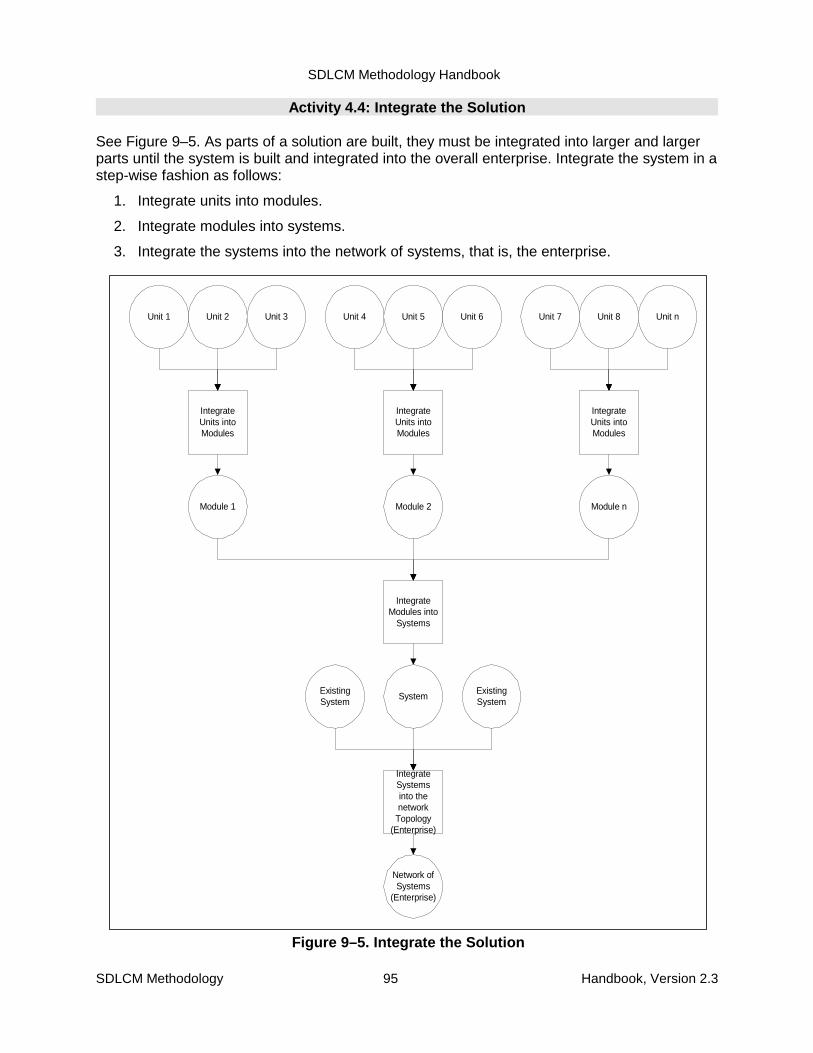
SDLCM Methodology Handbook
SDLCM Methodology 95 Handbook, Version 2.3
Unit 2
IntegrateUnits intoModules
Unit 1 Unit 3
Module 1
Unit 5
IntegrateUnits intoModules
Unit 4 Unit 6
Module 2
Unit 8
IntegrateUnits intoModules
Unit 7 Unit n
Module n
IntegrateModules into
Systems
System
IntegrateSystemsinto thenetwork
Topology(Enterprise)
Network ofSystems
(Enterprise)
ExistingSystem
ExistingSystem
Figure 9–5. Integrate the Solution
Activity 4.4: Integrate the Solution
See Figure 9–5. As parts of a solution are built, they must be integrated into larger and largerparts until the system is built and integrated into the overall enterprise. Integrate the system in astep-wise fashion as follows:
1. Integrate units into modules.
2. Integrate modules into systems.
3. Integrate the systems into the network of systems, that is, the enterprise.
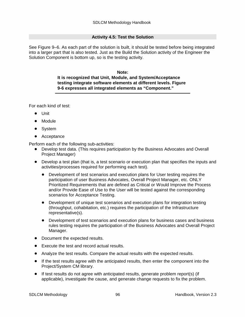
SDLCM Methodology Handbook
SDLCM Methodology 96 Handbook, Version 2.3
Activity 4.5: Test the Solution
See Figure 9–6. As each part of the solution is built, it should be tested before being integratedinto a larger part that is also tested. Just as the Build the Solution activity of the Engineer theSolution Component is bottom up, so is the testing activity.
For each kind of test:
� Unit
� Module
� System
� Acceptance
Perform each of the following sub-activities:� Develop test data. (This requires participation by the Business Advocates and Overall
Project Manager)
� Develop a test plan (that is, a test scenario or execution plan that specifies the inputs andactivities/processes required for performing each test).
� Development of test scenarios and execution plans for User testing requires theparticipation of user Business Advocates, Overall Project Manager, etc. ONLYPrioritized Requirements that are defined as Critical or Would Improve the Processand/or Provide Ease of Use to the User will be tested against the correspondingscenarios for Acceptance Testing.
� Development of unique test scenarios and execution plans for integration testing(throughput, cohabitation, etc.) requires the participation of the Infrastructurerepresentative(s).
� Development of test scenarios and execution plans for business cases and businessrules testing requires the participation of the Business Advocates and Overall ProjectManager.
� Document the expected results.
� Execute the test and record actual results.
� Analyze the test results. Compare the actual results with the expected results.
� If the test results agree with the anticipated results, then enter the component into theProject/System CM library.
� If test results do not agree with anticipated results, generate problem report(s) (ifapplicable), investigate the cause, and generate change requests to fix the problem.
Note:It is recognized that Unit, Module, and System/Acceptancetesting integrate software elements at different levels. Figure9-6 expresses all integrated elements as “Component.”
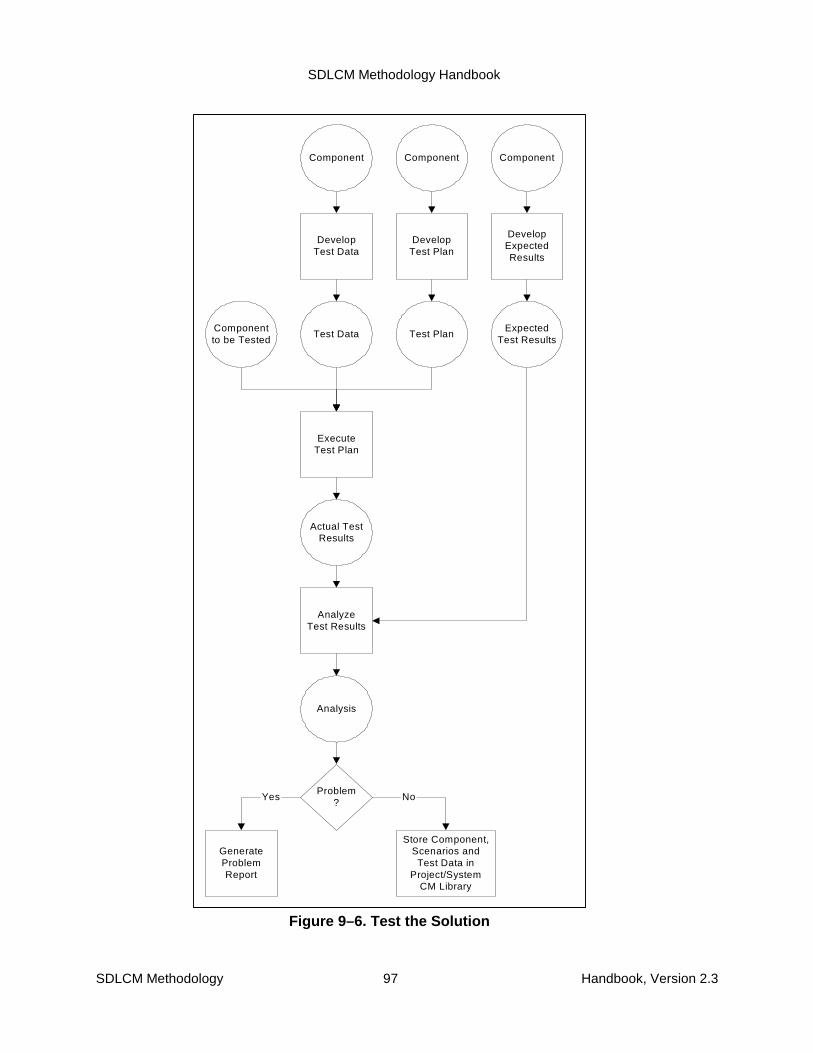
SDLCM Methodology Handbook
SDLCM Methodology 97 Handbook, Version 2.3
Component
Test Data
DevelopTest Data
Component
Test Plan
DevelopTest Plan
Component
ExpectedTest Results
DevelopExpectedResults
Componentto be Tested
ExecuteTest Plan
Actual TestResults
AnalyzeTest Results
Analysis
Problem?
GenerateProblemReport
Store Component,Scenarios andTest Data in
Project/SystemCM Library
Yes No
Figure 9–6. Test the Solution

SDLCM Methodology Handbook
SDLCM Methodology 98 Handbook, Version 2.3
Target Sites
TargetUsers
DefineTargetUsers
UpgradeRequire-
ments
DetermineNeeds forUpgrades
Createschedule for
upgrades
UpgradesSchedule
CreateInstallationSchedule
andInstructions
InstallationSchedule/
Instructions
Update theTIP
Updated TIP
Figure 9–7. Create the Rollout Strategy and Continue Deployment Planning
Activity 4.6: Create the Rollout Strategy and Continue Deployment Planning
See Figure 9–7. Given the locations and organizations that will receive the new informationmanagement system, develop a rollout strategy and document this in the Tactical IntegrationPlan. If appropriate, entries may be made to the SEN.
1. Define the target users
2. Survey the target users desktops to determine their capabilities and needs for upgrades(Target Users Capability Upgrade Request Form, F-6054)
3. Create a schedule for the upgrades
4. Create instruction and a schedule for the installation of the new system
5. Package the Rollout Strategy as part of the Tactical Integration Plan.
SDLCM Methodology Handbook
SDLCM Methodology 99 Handbook, Version 2.3
PDD
Updatepolicies andprocedures
New policiesand
procedures
Old policiesand
proceduresSOC
Figure 9–8. Update Policies and Procedures
Activity 4.7: Update Policies and Procedures
See Figure 9–8. Update appropriate policies and procedures (for example, productionschedules, business guidance (MD, Rule Change, etc.) or support).

SDLCM Methodology Handbook
SDLCM Methodology 100 Handbook, Version 2.3
IntegratedEducation,
Training, andReferenceMaterials
User Guides
ProduceTrainingMaterials
Help System Tutorials
Create aCustomerSupportCenter
CustomerSupportcenter
ProjectManagement
Plan
Develop auser trainingdelivery plan
User Skills
UserTraining andOrientation
Plan
TrainingMaterials
IntegratedEducation,
Training, andReferenceMaterials
SupportRequirements
OperationalSupportGuide
Figure 9–9. Build the User Manual and Training Materials
Activity 4-8: Build the User Manual and Training Materials
See Figure 9–9. Using (a) the plan for building an integrated set of education, training, andsupport materials from the Design the Solution component, (b) the design, and (c) the actualsystem specifications, build the materials to support the users.
� Produce user guides
� Produce a help system
� Produce operational guides
� Produce tutorials
� Create and maintain a customer support center
� Develop a user training plan
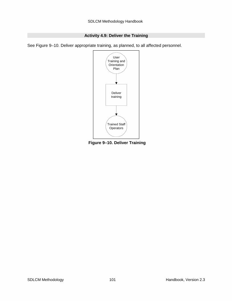
SDLCM Methodology Handbook
SDLCM Methodology 101 Handbook, Version 2.3
Delivertraining
Trained StaffOperators
UserTraining andOrientation
Plan
Figure 9–10. Deliver Training
Activity 4.9: Deliver the Training
See Figure 9–10. Deliver appropriate training, as planned, to all affected personnel.
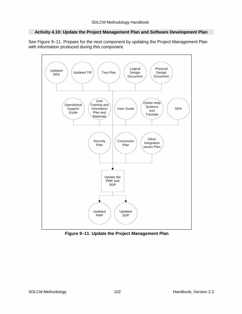
SDLCM Methodology Handbook
SDLCM Methodology 102 Handbook, Version 2.3
Update thePMP and
SDP
Updated TIP Test PlanLogicalDesign
Document
UpdatedPMP
UpdatedSRS
OperationalSupportGuide
UserTraining andOrientationPlan andMaterials
User Guide
Online HelpSystems
andTutorials
SEN
PhysicalDesign
Document
SecurityPlan
ConversionPlan
OtherIntegrationIssues Plan
UpdatedSDP
Figure 9–11. Update the Project Management Plan
Activity 4.10: Update the Project Management Plan and Software Development Plan
See Figure 9–11. Prepare for the next component by updating the Project Management Planwith information produced during this component.

SDLCM Methodology Handbook
SDLCM Methodology 103 Handbook, Version 2.3
Review
UpdatedPMP and
SDP
Go or No-GoDecision Form
Project Form, F-1154
Updated TIP Test PlanLDD and
PDDUpdated
SRS
OperationalSupportGuide
UserTraining andOrientation
Plan
User Guide
Online HelpSystems
andTutorials
SEN
TransferProject-
LevelProducts to
CCMOrganization
Central CMLibrary
Central CMProcedures
Documents,Products
and Artifacts
Figure 9–12. Review (Component 4)
Activity 4.11: Review (Component 4) and Transfer Materials to Central ConfigurationManagement
See Figure 9–12. Review the results of the activities that were performed in this component todetermine if the system should be deployed. Include the Records Management organization inthis review activity. After review and approval, transfer all Project-level products and materialsto Central Configuration Management (CCM)
SDLCM Methodology Handbook
SDLCM Methodology 104 Handbook, Version 2.3
10. Component 5. Deploy the Solution10.1 Purpose
The purpose of this component is to roll out the integrated solution, which includes:
� Review and update deployment plans and announce deployment
� Validate the environment and update it if required
� Install the solution in a full test environment (modeled to production)
� Test the installed solution (full integration and operational)
� Implement Business Policies and Procedures
� Training the users
� User and Acceptance test of the system
� Review the results of the deployment and test
� Prepare feedback reports for all testing
� Obtain user approval
� Update the Production Environment
� Deploy/Install the new/updated system
� Cut over to a production environment
� Use the system
� Update the technical inventory
10.2 Roles and Responsibilities
The roles required to perform the activities in the Deploy the Solution component are shown inTable 10–1.
Table 10–1. Component 5 Roles and ResponsibilitiesRoles Responsibilities
Overall Project ManagerTechnical Project ManagerDevelopment Team
Accountable for Execution ofActivities
Business Advocate Approval to Proceed
SDLCM Methodology Handbook
Roles Responsibilities
SDLCM Methodology 105 Handbook, Version 2.3
Executive Sponsor
Business project Manager
Business SME
Technical SME
Other Representatives or Stakeholders
• Quality Assurance Manager
• Configuration management Manager
Provides Input
10.3 Entry Criteria
The following set of events trigger the initiation of Component 5:� System test completed
� Rollout plan completed
� Training plan and materials completed
� Installation instructions completed
� Regression test completed
� Customer acceptance
10.4 Input, Activities, and Outputs
The inputs to this component are as follows:� Project Management Plan
� Tactical Integration Plan, including
� Conversion Plan
� Rollout Plan
� User Training and Orientation Plan and materials
� Installation instructions
� Performance criteria measures
Figure 10–1 illustrates the flow of the following activities:1. Review and Update Plans and Announce Deployment
2. Validate and Upgrade the Operational Test Environment
3. Install the Solution
4. Test the Installed Solution
5. Analyze the Installed System Test Results
6. Test the Operational Support System
7. Analyze the Operational Support Test Results

SDLCM Methodology Handbook
SDLCM Methodology 106 Handbook, Version 2.3
8. Implement Policies and Procedures
9. Train the Users
10. User Test the Solution
11. Analyze the User Test Results
12. Acceptance Test the Solution
13. Analyze the Acceptance Test Results
14. Validate and Upgrade the Production
15. Deploy the Solution to Production Environment
16. Review (Component 5)
The inputs to this component were produced as products of Component 4.
As the figure suggests, many of the activities can be performed in parallel. The activities aredescribed in more detail in Section 3.10.
Figure 10–1 also summarizes the outputs of all Component 5 activities in the central data store.
Appendix C includes a summary description of all products of NRC projects, indicates withinwhich components each product is created and updated, and specifies which products arerequired.The products, whose standard and form numbers are shown in the figure, are described inmore detail in the companion volume SDLCM Methodology Procedures, Standards, and Forms.
10.5 Techniques and Tools
The activities of Component 5 are supported by the following techniques.� Structured Facilitation
� Structured Walkthrough
� Peer Review
Refer to the current SDLCM Methodology Tool Inventory for the recommended set of tools.
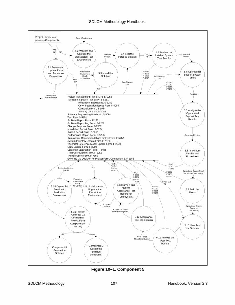
SDLCM Methodology Handbook
SDLCM Methodology 107 Handbook, Version 2.3
Project Management Plan (PMP), S-1052Tactical Integration Plan (TIP), S-5051
Installation Instructions, S-5252Other Integration Issues Plan, S-5055Conversion Plan, S-1054Security Controls, S-1056
Software Engineering Notebook, S-3091Test Plan, S-5151Problem Report Form, F-2251Problem Report Log Form, F-2252Change Proposal Form, F-2502Installation Report Form, F-5254Rollout Report Form, F-5255Performance Report Form, F-5256Deployment Recommendations for Fix Form. F-5257System Inventory Update Form, F-2071Technical Reference Model Update Form, F-2073GILS Update Form, F-3060Customer Satisfaction Form, F-6055Final User Signoff Form, F-6056Trained Users Form, F-7151Go or No Go Decision for Project Form, Component 5, F-1155
5.1 Review andUpdate Plansand AnnounceDeployment
5.2 Validate andUpgrade the
Operational TestEnvironment
5.3 Install theSolution
5.4 Test theInstalled Solution
5.5 Analyze theInstalled System
Test Results
5.15 Deploy theSolution toProduction
Environment
5.16 Review(Go or No GoDecision forProject Form
Component 5,F-1155)
Component 6Service the
Solution
Project Library fromprevious Components
PAPTIP
5.12 AcceptanceTest the Solution
5.9 Train theUsers
F-2251F-2252F-5256F-5257
DeploymentAnnouncement
TIP
OperationalEnvironment
Readyfor Solution
F-5254
InstalledSystem
Test Plan andTIP
TestLog
Operational System Readyfor Training and Testing
F-2502F-2251F-7151
SENF-2502F-2251F-6055F-6056
Operational SystemReady for
User Testing
Production SystemF-5255
PMPTIP
Go No Go
Current Environment
5.6 OperationalSupport System
TestingTest Plan and
TIP
IntegratedSystem
5.7 Analyze theOperational
Support TestResults
Test Log
F-2251F-2252F-5256F-5257
5.8 ImplementPolicies andProcedures
F-2071F-2073F-3060
Operational System
5.10 User Testthe Solution
Test Plan andTIP
Test Log5.11 Analyze the
User TestResults
F-2251F-2252F-5256F-5257
User TestedOperational System
5.13 Review andAnalyze
Acceptance TestResults forDeployment
5.14 Validate andUpgrade theProduction
Environment
F-2251F-2252F-5256F-5257
AcceptedSystem
Acceptance TestedOperational System
ProductionEnvironment
Readyfor Solution
TIP
Component 3Design the
Solution(for rework)
Figure 10–1. Component 5

SDLCM Methodology Handbook
SDLCM Methodology 108 Handbook, Version 2.3
10.6 Exit Criteria
Component 5 Is complete when:� All critical products have been reviewed (structured walkthrough or peer review)
� Key products have been inspected by QA to conform to project standards
� Products have been placed under CM control
� Information has been shared
� Issues have been resolved
� There is management buy-in to move forward
� There are no reasons to stop this project now
10.7 Component 5 Activity Details
The following pages provide detailed activities of Component 5, Deploy the Solution.

SDLCM Methodology Handbook
SDLCM Methodology 109 Handbook, Version 2.3
ProjectManagement
Plan
DeploymentAnnounce-
ment
Review andCreate
Announce-ment
TIP
Awareness
AnnounceDeployment
Schedule
Figure 10–2. Review and Update Plans and Announce Deployment
Activity 5.1: Review and Update Plans and Announce Deployment
See Figure 10–2. Review the Project Management Plan and TIP, and announce thedeployment. It is important to prepare people to expect deployment activities.

SDLCM Methodology Handbook
SDLCM Methodology 110 Handbook, Version 2.3
Activity 5.2: Validate and Upgrade the Operational Test Environment
See Figure 10–3. Using the TIP:1. Validate the operational test environment (workstation and host or client and server) to
determine what the system needs to run and whether the system will run in eachindividual user environment.
2. If needed, procure and install any additional hardware and software.
3. Upgrade the operational test environment.

SDLCM Methodology Handbook
SDLCM Methodology 111 Handbook, Version 2.3
EnvironmentRequire-
ments (fromTIP)
HW & SWDiscre-pancies
ValidateEnvironment
Environment
HW & SW
Procure HW& SW asNeeded
UpgradedEnvironment
UpgradeEnvironment
Discre-pancies?
Yes
EnvironmentReady forSolution
No
Figure 10–3. Validate and Upgrade the Environment
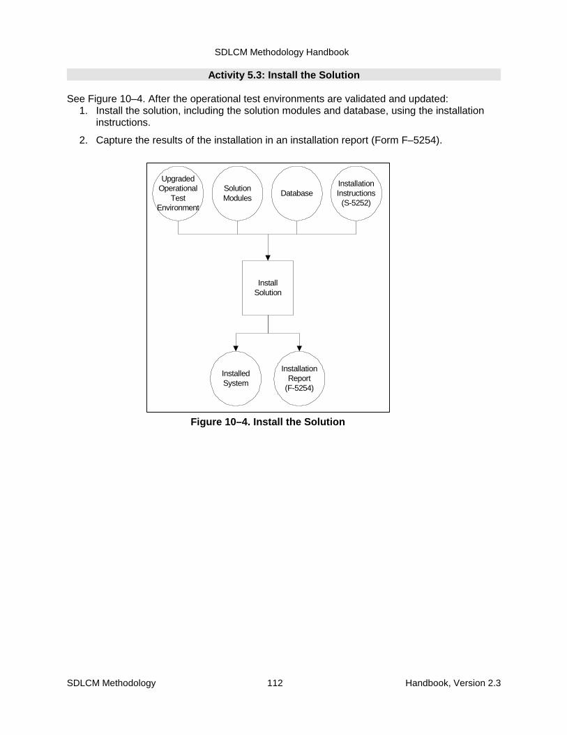
SDLCM Methodology Handbook
SDLCM Methodology 112 Handbook, Version 2.3
SolutionModules
InstalledSystem
InstallSolution
DatabaseInstallationInstructions
(S-5252)
InstallationReport
(F-5254)
UpgradedOperational
TestEnvironment
Figure 10–4. Install the Solution
Activity 5.3: Install the Solution
See Figure 10–4. After the operational test environments are validated and updated:1. Install the solution, including the solution modules and database, using the installation
instructions.
2. Capture the results of the installation in an installation report (Form F–5254).
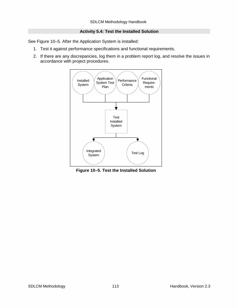
SDLCM Methodology Handbook
SDLCM Methodology 113 Handbook, Version 2.3
InstalledSystem
TestInstalledSystem
ApplicationSystem Test
Plan
PerformanceCriteria
FunctionalRequire-ments
IntegratedSystem
Test Log
Figure 10–5. Test the Installed Solution
Activity 5.4: Test the Installed Solution
See Figure 10–5. After the Application System is installed:
1. Test it against performance specifications and functional requirements.
2. If there are any discrepancies, log them in a problem report log, and resolve the issues inaccordance with project procedures.

SDLCM Methodology Handbook
SDLCM Methodology 114 Handbook, Version 2.3
AnalyzeTest Results
Discre-pancies?
ProblemReports
FeedbackReports(F-5257)
Test Log
SystemReady for
OperationalSupport Test
(F-5256)
No Yes
CMProcedure
Figure 10–6. Analyze the Test Results
Activity 5.5: Analyze the Installed System Test Results
See Figure 10–6. Using the results of the Application System test:
1. Review the test results. Log your analysis in a feedback report.
2. If there are discrepancies, log them as problem reports (Forms F–2251 and F–2252) tobe resolved in accordance with proper procedures.
3. If there are no discrepancies, then the system is ready for operational support testing.

SDLCM Methodology Handbook
SDLCM Methodology 115 Handbook, Version 2.3
IntegratedSystem
TestIntegrated
System
OperationalSystem Test
Plan
PerformanceCriteria
FunctionalRequire-
ments
Test LogOperational
System
Figure 10–7. Test the Integrated System
Activity 5.6: Test the Operational Support System
See Figure 10–7. After the Application System has completed System Integration Test:
1. Test the Integrated System against performance specifications and functionalrequirements viewed from the operational support perspective.
2. If there are any discrepancies, log them in a problem report log, and resolve the issues inaccordance with project procedures.

SDLCM Methodology Handbook
SDLCM Methodology 116 Handbook, Version 2.3
AnalyzeTest Results
Discre-pancies?
ProblemReports
FeedbackReports(F-5257)
Test Log
SystemReady for
Training andUser Test(F-5256)
No Yes
CMProcedure
Figure 10–8. Analyze the Test Results
Activity 5.7: Analyze the Operational Support Test Results
See Figure 10–8. Using the results of the system test:
1. Review the test results. Log your analysis in a feedback report.
2. If there are discrepancies, log them as problem reports (Forms F–2251 and F–2252) tobe resolved in accordance with proper procedures.
3. If there are no discrepancies, then the system is ready to be used to train the users.

SDLCM Methodology Handbook
SDLCM Methodology 117 Handbook, Version 2.3
OperationalSystem
Implementupdated
policies andprocedures
New policiesand
procedures
Updatedpolicies andprocedures
Figure 10–9. Implement Policies andProcedures
Activity 5.8: Implement Policies and Procedures
See Figure 10–9. After the system has been installed, tested, and in the operational state,implement the policies and procedures (for example, production schedules or support) thatwere updated in Component 4, Activity 4.8.
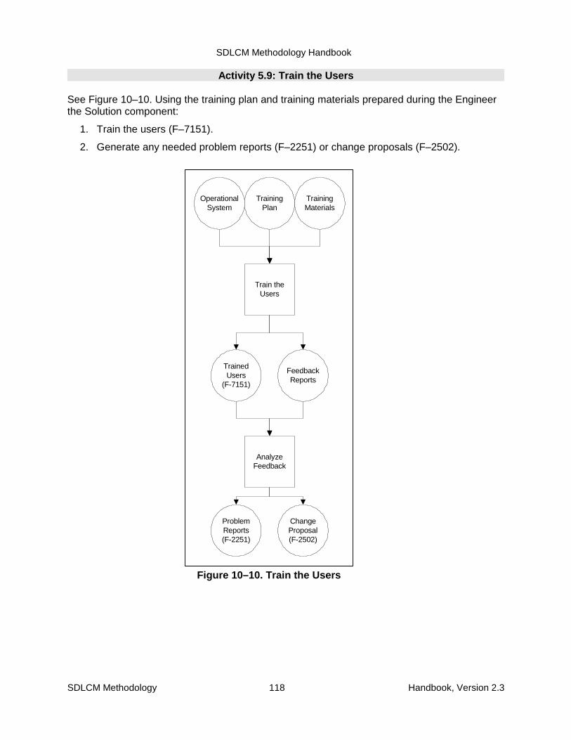
SDLCM Methodology Handbook
SDLCM Methodology 118 Handbook, Version 2.3
OperationalSystem
FeedbackReports
Train theUsers
TrainingPlan
TrainingMaterials
AnalyzeFeedback
ChangeProposal(F-2502)
TrainedUsers
(F-7151)
ProblemReports(F-2251)
Figure 10–10. Train the Users
Activity 5.9: Train the Users
See Figure 10–10. Using the training plan and training materials prepared during the Engineerthe Solution component:
1. Train the users (F–7151).
2. Generate any needed problem reports (F–2251) or change proposals (F–2502).

SDLCM Methodology Handbook
SDLCM Methodology 119 Handbook, Version 2.3
OperationalSystem
TestOperational
System
User TestPlan
PerformanceCriteria
FunctionalRequire-
ments
Test LogUser TestedOperational
System
Figure 10–11. User Test the Solution
Activity 5.10: User Test the Solution
See Figure 10–11. After the Operational System has completed Operational Support SystemIntegration Test:
1. Test the Operational System against performance specifications and functionalrequirements viewed from the users’ perspective.
2. If there are any discrepancies, log them in a problem report log, and resolve the issues inaccordance with project procedures.

SDLCM Methodology Handbook
SDLCM Methodology 120 Handbook, Version 2.3
AnalyzeTest Results
Discre-pancies?
ProblemReports
FeedbackReports(F-5257)
User TestLog
SystemReady for
AcceptanceTest
(F-5256)
No Yes
CMProcedure
Figure 10–12. Analyze the User TestResults
Activity 5.11: Analyze the User Test Results
See Figure 10–12. Using the results of the user test of the system:
1. Review the test results. Log your analysis in a feedback report.
2. If there are discrepancies, log them as problem reports (Forms F–2251 and F–2252) tobe resolved in accordance with proper procedures.
3. If there are no discrepancies, then the system is ready to be acceptance tested by thecustomer.
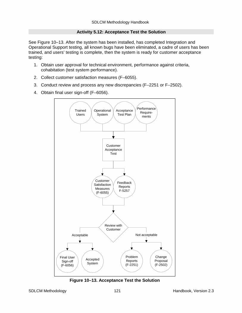
SDLCM Methodology Handbook
SDLCM Methodology 121 Handbook, Version 2.3
OperationalSystem
FeedbackReportsF-5257
CustomerAcceptance
Test
AcceptanceTest Plan
PerformanceRequire-ments
TrainedUsers
CustomerSatisfactionMeasures(F-6055)
Final UserSign-off(F-6056)
Review withCustomer
Not acceptable
ChangeProposal(F-2502)
ProblemReports(F-2251)
AcceptedSystem
Acceptable
Figure 10–13. Acceptance Test the Solution
Activity 5.12: Acceptance Test the Solution
See Figure 10–13. After the system has been installed, has completed Integration andOperational Support testing, all known bugs have been eliminated, a cadre of users has beentrained, and users’ testing is complete, then the system is ready for customer acceptancetesting:
1. Obtain user approval for technical environment, performance against criteria,cohabitation (test system performance).
2. Collect customer satisfaction measures (F–6055).
3. Conduct review and process any new discrepancies (F–2251 or F–2502).
4. Obtain final user sign-off (F–6056).

SDLCM Methodology Handbook
SDLCM Methodology 122 Handbook, Version 2.3
AnalyzeTest Results
Discre-pancies?
ProblemReports
FeedbackReports(F-5257)
AcceptanceTest Log
SolutionModules
Ready forDeployment
(F-4051)
No Yes
CMProcedure
Figure 10–14. Analyze the Acceptance TestResults
Activity 5.13: Analyze the Acceptance Test Results
See Figure 10–14. Using the results of the acceptance test of the system:
1. Review the test results. Log your analysis in a feedback report.
2. If there are discrepancies, log them as problem reports (Forms F–2251 and F–2252) tobe resolved in accordance with proper procedures.
3. All appropriate entities evaluate project readiness for production. Appropriate entitiesmust include:
• Overall Project Manager
• Technical Project Manager
• Operational Support
4. If there are no discrepancies, then the system is ready to be moved to production.Secure approvals on Form F-4051 prior to moving the system to the next activity.

SDLCM Methodology Handbook
SDLCM Methodology 123 Handbook, Version 2.3
Activity 5.14: Validate and Upgrade the Production Environment
See Figure 10–15. Using the TIP:
1. Validate the production environment (workstation and host or client and server) todetermine what the system needs to run and whether the system will run in eachindividual user environment.
2. If needed, procure and install any additional hardware and software.
3. Upgrade the production environment.
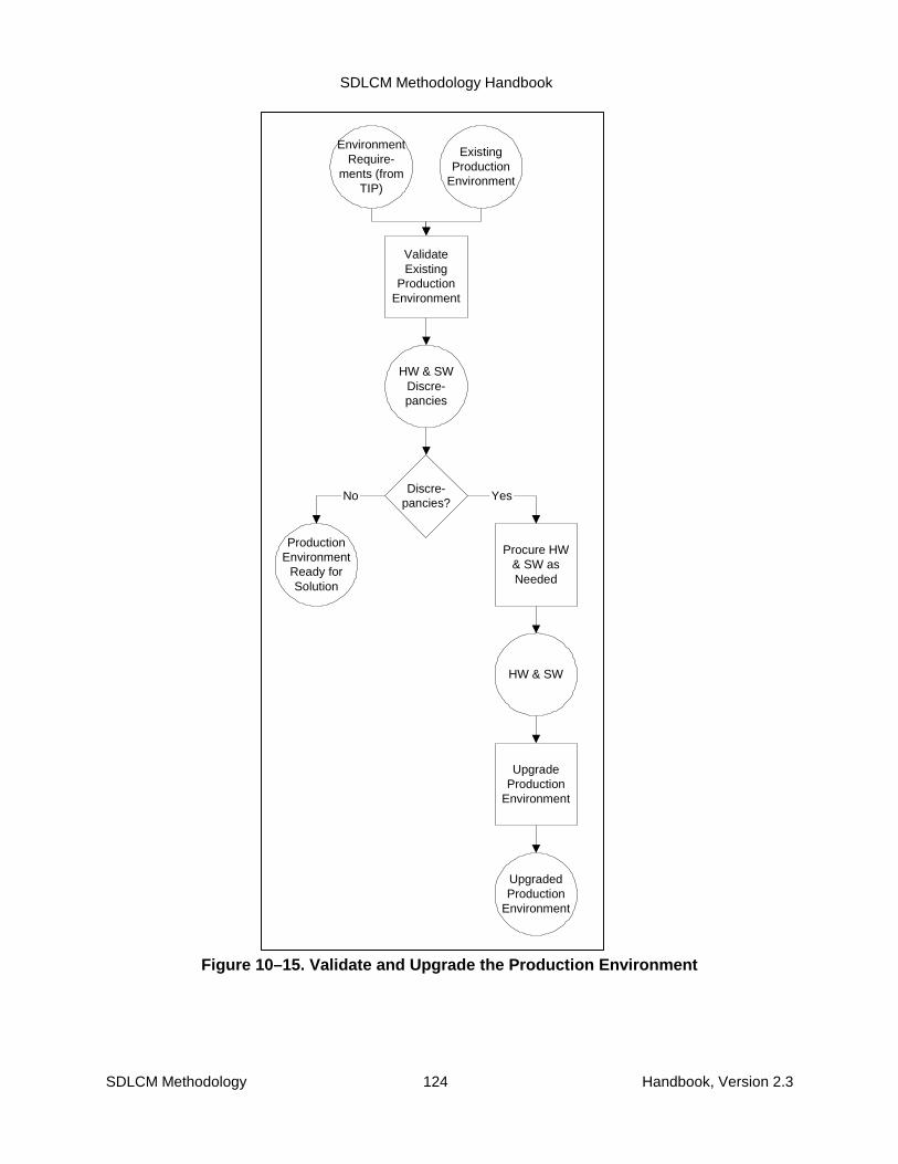
SDLCM Methodology Handbook
SDLCM Methodology 124 Handbook, Version 2.3
EnvironmentRequire-
ments (fromTIP)
HW & SWDiscre-pancies
ValidateExisting
ProductionEnvironment
ExistingProduction
Environment
HW & SW
Procure HW& SW asNeeded
UpgradedProduction
Environment
UpgradeProduction
Environment
Discre-pancies?
Yes
ProductionEnvironment
Ready forSolution
No
Figure 10–15. Validate and Upgrade the Production Environment
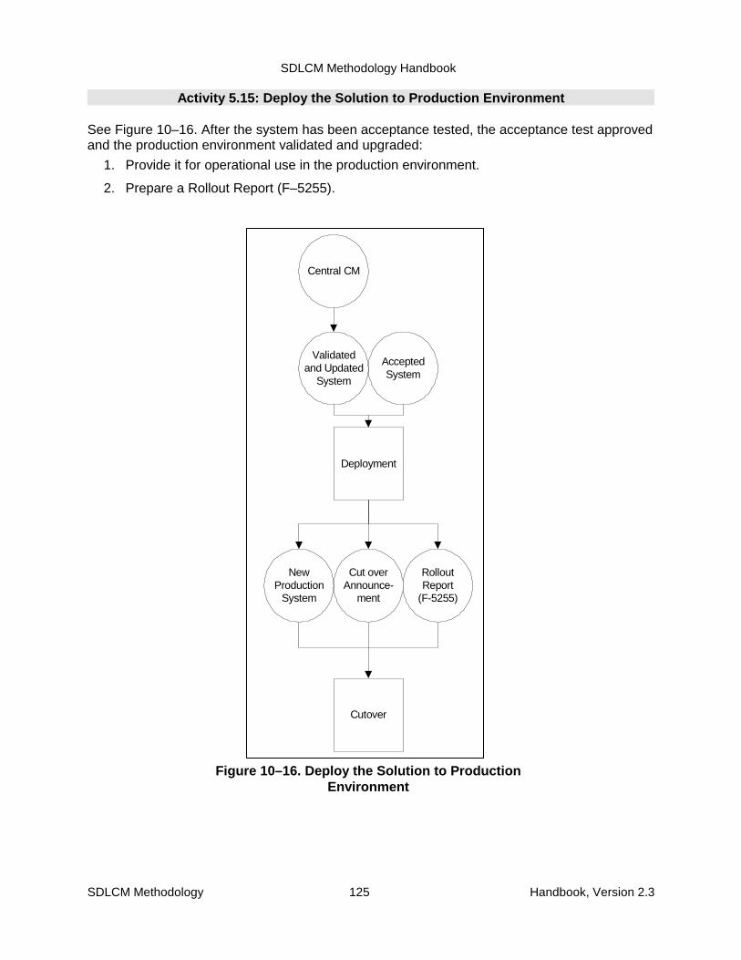
SDLCM Methodology Handbook
SDLCM Methodology 125 Handbook, Version 2.3
Cut overAnnounce-
ment
Deployment
NewProduction
System
RolloutReport
(F-5255)
AcceptedSystem
Validatedand Updated
System
Central CM
Cutover
Figure 10–16. Deploy the Solution to ProductionEnvironment
Activity 5.15: Deploy the Solution to Production Environment
See Figure 10–16. After the system has been acceptance tested, the acceptance test approvedand the production environment validated and upgraded:
1. Provide it for operational use in the production environment.
2. Prepare a Rollout Report (F–5255).

SDLCM Methodology Handbook
SDLCM Methodology 126 Handbook, Version 2.3
NewProduction
System
FeedbackReports
Review
Go or No-GoDecision Form
Project Form, F-1155
Figure 10–17. Review (Component 5)
Activity 5.16: Review (Component 5)
See Figure 10–17. After the system has been installed, tested, and approved for productionuse, review the status to decide whether to move into the Component 6, Service the Solution.The outcomes of this evaluation are that the system will either move to Component 6 or, shouldthere be problems precluding that movement, the system moves back to Component 3 forrework to correct the problems.

SDLCM Methodology Handbook
SDLCM Methodology 127 Handbook, Version 2.3
EnhancementEnhancement
Release-Based MaintenanceCorrective ChangesAdaptive Changes
Perfective ChangesPreventive Changes
Release-Based MaintenanceCorrective ChangesAdaptive Changes
Perfective ChangesPreventive Changes
Emergency Maintenance
Emergency Maintenance
Change ManagementEstablish Change Management
Control System ChangesTrack and Report System Changes
Change ManagementEstablish Change Management
Control System ChangesTrack and Report System Changes
Release ManagementPlan Release
Coordinate Release ChangesTrack Release Changes
Track Release
Release ManagementPlan Release
Coordinate Release ChangesTrack Release Changes
Track Release
Figure 11–1. High-Level View of Servicing the Solution
11. Component 6. Service the Solution11.1 Component Overview
The purpose of Component 6, Service the Solution, is to maintain or enhance an existingapplication or its support environment.
This component is necessarily very different from the first five components. The presentation inthis chapter is also necessarily very different.
Figure 11–1 provides a high-level illustration of the structure of Component 6. Three differentapproaches to servicing a solution are shown within the broken line at the bottom of the figure:
� Enhancement
� Release-based maintenance
� Emergency maintenance
Those three approaches are supported by two illustrated elements of configurationmanagement:
� Change management
� Release management
Change management evaluates Change Proposals (which may be contractual requests forapplication system modifications) and Problem Reports and routes them appropriately.
SDLCM Methodology Handbook
SDLCM Methodology 128 Handbook, Version 2.3
Emergency changes are routed to emergency maintenance. Routine changes are allocated toreleases and proceed to release planning. A major change is treated as an enhancement.
Release management takes a defined release, plans the release, and manages changes tothe release during its development. One result of planning the release is its division into workpackages for assignment to different teams.
Enhancement typically requires a major change to some part of an existing application system,perhaps to the system architecture or to the support environment. Often it is a customer whodeclares a change to be an enhancement. Within the SDLCM Methodology, an enhancement istreated the same as a new development effort; that is, by beginning with Component 1 andproceeding through the first five components. This approach provides adequate visibility to theenhancement Project and ensures that the system documentation will be updated to reflect themajor change. The enhancement process is, therefore, not addressed further in this chapter.
Release-based maintenance is the process of taking a defined work package and defining,executing, and testing the required changes.
Emergency maintenance is an alternative to release-based maintenance for changesrequiring immediate action. These types of changes, which are the exception rather than therule, are followed up with a normal release-based maintenance process.
Figure 11–2 provides a process flow diagram for the top level activities of Component 6showing the triggers and results. This figure also shows that the output of release-basedmaintenance flows into integration and then to deployment. Integration is the process of takingthe defined work package and integrating it with any other work packages to be deployed.Deployment refers to installing and rolling out the integrated solution. Both are discussed inother chapters of this handbook.
The remainder of this chapter is organized around the major processes of changemanagement, release management, release-based (routine) maintenance, and emergencymaintenance. An iconic representation of Figure 11–1 appears at the beginning of each sectionas a reminder of the relationships among the major processes. For each major process, thefollowing are examined and discussed:
� Activities performed
� Roles that perform those activities
� Products produced
� Critical dependencies
� Configuration management of the products
� Quality assurance
Roles, activities, products, and flow are summarized in:
� Process flow diagrams
� Data flow diagrams
� Activity to work product matrices
� Activity role matrices
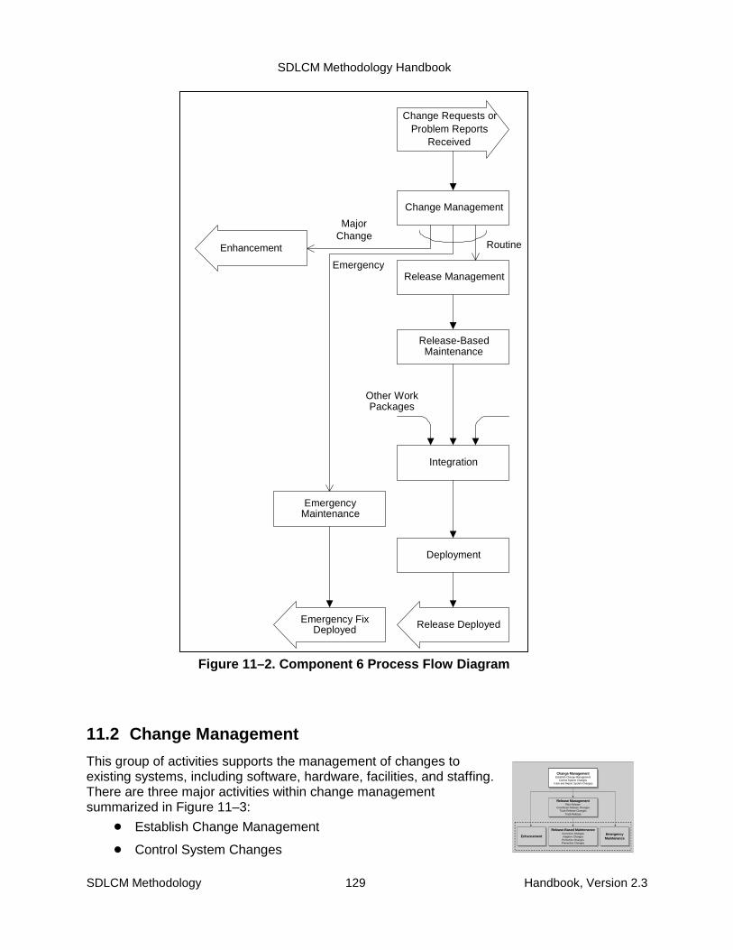
SDLCM Methodology Handbook
SDLCM Methodology 129 Handbook, Version 2.3
EnhancementEnhancement
Release-Based MaintenanceCorrective ChangesAdaptive ChangesPerfective ChangesPreventive Changes
Release-Based MaintenanceCorrective ChangesAdaptive ChangesPerfective ChangesPreventive Changes
Emergency Maintenance
Emergency Maintenance
Change ManagementEstablish Change Management
Control System ChangesTrack and Report System Changes
Change ManagementEstablish Change Management
Control System ChangesTrack and Report System Changes
Release ManagementPlan Release
Coordinate Release ChangesTrack Release Changes
Track Release
Release ManagementPlan Release
Coordinate Release ChangesTrack Release Changes
Track Release
Change Management
Release Management
Release-BasedMaintenance
Integration
Deployment
Release DeployedEmergency FixDeployed
EmergencyMaintenance
Other WorkPackages
Emergency
RoutineEnhancement
MajorChange
Change Requests orProblem Reports
Received
Figure 11–2. Component 6 Process Flow Diagram
11.2 Change Management
This group of activities supports the management of changes toexisting systems, including software, hardware, facilities, and staffing.There are three major activities within change managementsummarized in Figure 11–3:
� Establish Change Management
� Control System Changes
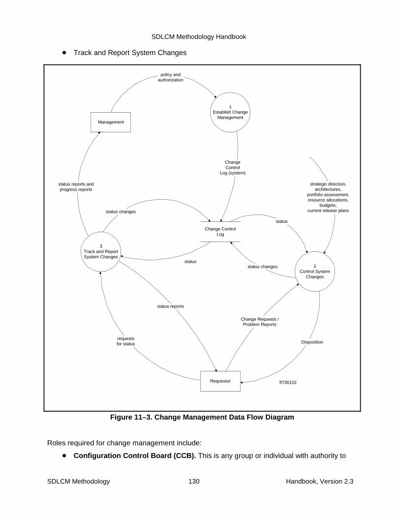
SDLCM Methodology Handbook
SDLCM Methodology 130 Handbook, Version 2.3
1Establish Change
Management
2Control System
Changes
3Track and ReportSystem Changes
Change ControlLog
Requestor
ChangeControl
Log (system)
status changes
Change Requests /Problem Reports
status
status reports
status changes
status
Dispositionrequestsfor status
Management
status reports andprogress reports
ft730102
strategic direction,architectures,
portfolio assessment,resource allocations,
budgets,current release plans
policy andauthorization
Figure 11–3. Change Management Data Flow Diagram
� Track and Report System Changes
Roles required for change management include:
� Configuration Control Board (CCB). This is any group or individual with authority to

SDLCM Methodology Handbook
SDLCM Methodology 131 Handbook, Version 2.3
review and approve changes. There may be a single CCB or multiple CCBs to handlechanges of different scope or magnitude. A CCB may be a single individual. (See theConfiguration Management chapter for more information.)
� Configuration Management Office (CMO). This is the administrative arm of the CCB.This may be one person or a group.
� Systems engineering. This group of architects and analysts on the development ormaintenance team evaluates the technical requirements of a change proposal orproblem report and estimates the effort, cost, and schedule to implement it.
� Requester. This is anyone who requests a change or requests information regardingthe status of a change. It may be a user, developer, operator, manager, or anyone elsewith an interest in the system.
� Management. This is meant to include anyone with global interest in the changemanagement process and progress in clearing change proposals and problem reports.It may include the CCB, executive management, business function managers, andothers.
The following three subsections discuss the steps involved in the Change Managementactivities and the roles and products associated with those activities.
11.2.1 Establish Change Management
Establishing change management involves establishing the organizations, roles,responsibilities, processes, policies, procedures, tools, and standards to control changes toexisting systems. System changes must be controlled through an orderly process to preventdefects and failures and to maximize business value added.
Change management is an integral function of Configuration Management, which is covered inChapter 5 of this handbook. For the purposes of this chapter, it is sufficient to know thatConfiguration Management is responsible for performing the following activities, which play akey role in servicing the solution:
� Acquire and set up the tools to support change management, including an automatedChange Control Log.
� Develop a Change Proposal form.
� Develop a change management process covering the requesting, evaluating,approving, allocating, tracking, and reporting of system changes.
� Identify the organizations, roles, and responsibilities for performing the changemanagement process.
� Determine the rules for routing different categories of problems, changes, and issuesbased on category, size (or effort or cost), and risk.
� Develop standards and procedures for completing change proposals.
� Document the policies, procedures, and standards to implement the changemanagement process.
� Communicate the change management policies, procedures, and standards to theorganization.
The outputs of the change management function that help support servicing the solution are:

SDLCM Methodology Handbook
SDLCM Methodology 132 Handbook, Version 2.3
� Change Control Log (tracking and reporting system)
� Change Proposal form (input document)
� Change Management Policies, Procedures, and Standards
11.2.2 Control System Changes
A report of a problem or a request for a system change may trigger the Control System Changeactivity as shown in the process flow diagram (see Figure 11–4). The data flow diagram (seeFigure 11–5) illustrates the flow of data among the ten lower level activities:
1. Create and Register Change Proposals. Initiate the change process by creating andregistering Change Proposals. Changes may originate from various sources includingusers, managers, maintainors, and operators. Changes may originate as a trouble callto a help desk or a completed Change Proposal form.
2. Research, Validate, and Complete Change Proposals. Make sure the problem orChange Proposal is well defined, properly classified, and valid; complete theinformation on the request; and assemble all necessary support information. Theimportant point is to make sure the request is adequately documented without requiringexcessive documentation that would slow down the process.
3. Batch Change Proposals. Review the Change Proposals to determine whether andhow they should be batched into Change Packages for further analysis as a unit.Different reported problems might have the same root cause; they may be symptoms ofone underlying problem. Several Change Proposals may be satisfied by one generalsolution. The idea is to see the larger picture.
4. Analyze Problems. Analyze a problem to determine its root cause and to proposepotential solutions.
5. Propose Changes. Propose the specific technical changes required to implement theChange Proposals. By the end of this activity, you should have described the proposedchanges in system terms, but you may not have identified all the various componentsaffected by the change.
6. Analyze Impacts. Analyze the impact of a proposed change. If not done already,translate the change into system terms and identify all the components affected by thechange. At this point, it is not necessary to specify all the changes required but to get asense for the size of the effort required—counts may be sufficient—so the CCB willhave a sufficient basis for evaluating the merits of the change. Another round of impactanalysis will occur early in development, once the requirements have been determined.
7. Estimate Effort, Cost, and Schedule. Estimate the effort, cost, and schedule for thechange, now that the scope is understood, in order to give the users sufficientinformation to approve or withdraw a proposed change, or a CCB sufficient informationto accept or reject a change.
8. Assess Cost and Benefit. Combine the cost, benefit, and schedule information into acost-benefit analysis that will enable the CCB to review the change as a businessdecision.
9. Prepare Change Packages for CCB Review. Assemble Change Packagedocumentation and route the changes to the proper CCBs for review and action. Thecriteria used to route Change Packages to different groups should include size, scope,

SDLCM Methodology Handbook
SDLCM Methodology 133 Handbook, Version 2.3
and urgency.
10. Review and Allocate Change Packages. CCBs review the Change Packages formerit and priority and then allocate them to particular releases. In doing this, the CCBmay remove individual changes from a Change Package and put them in anotherChange Package, reject them, or defer them indefinitely without assignment to arelease. Likewise, the CCB may reject entire Change Packages or defer themindefinitely without assigning them to a release.

SDLCM Methodology Handbook
SDLCM Methodology 134 Handbook, Version 2.3
Figure 11–4. Control System Changes, ProcessFlow Diagram

SDLCM Methodology Handbook
SDLCM Methodology 135 Handbook, Version 2.3
Requestor
1 Create and register Change Request
2 Research,
Validate, and Complete Change
Requests
3 Batch Change Requests for
Analysis
5 Propose Changes
6 Analyze Impacts
7 Estimate Effort,
Cost, and Schedule
4 Analyze Problems
8 Assess Cost/
Benefit
9 Prepare Change
Packages for CCB Review
10 Review and
Allocate Change Packages
Change Control Log
requested change reported problem
Change Request
Problem Analysis Report
proposed changes Impact Analysis
Report
Cost and Schedule Estimate
Cost/Benefit Analysis
Change Packages (ready for CCB review)
status update
disposition of change
Change Request (completed)
Change Packages
initial entry
status update
status update
status update
Figure 11–5. Control System Changes, Data Flow Diagram
Table 11–2 associates the ten activities with the roles responsible for their execution.
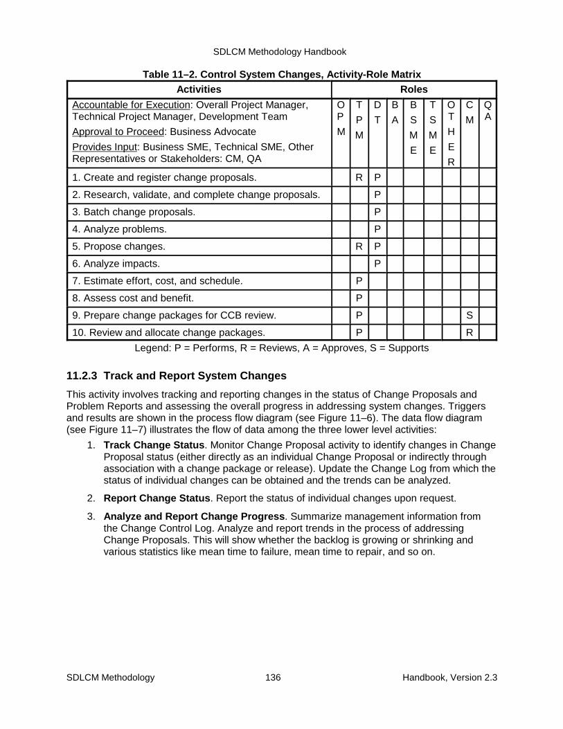
SDLCM Methodology Handbook
SDLCM Methodology 136 Handbook, Version 2.3
Table 11–2. Control System Changes, Activity-Role MatrixActivities Roles
Accountable for Execution: Overall Project Manager,Technical Project Manager, Development Team
Approval to Proceed: Business Advocate
Provides Input: Business SME, Technical SME, OtherRepresentatives or Stakeholders: CM, QA
OP
M
T
P
M
D
T
B
A
B
S
M
E
T
S
M
E
OT
H
E
R
C
M
QA
1. Create and register change proposals. R P
2. Research, validate, and complete change proposals. P
3. Batch change proposals. P
4. Analyze problems. P
5. Propose changes. R P
6. Analyze impacts. P
7. Estimate effort, cost, and schedule. P
8. Assess cost and benefit. P
9. Prepare change packages for CCB review. P S
10. Review and allocate change packages. P R
Legend: P = Performs, R = Reviews, A = Approves, S = Supports
11.2.3 Track and Report System Changes
This activity involves tracking and reporting changes in the status of Change Proposals andProblem Reports and assessing the overall progress in addressing system changes. Triggersand results are shown in the process flow diagram (see Figure 11–6). The data flow diagram(see Figure 11–7) illustrates the flow of data among the three lower level activities:
1. Track Change Status. Monitor Change Proposal activity to identify changes in ChangeProposal status (either directly as an individual Change Proposal or indirectly throughassociation with a change package or release). Update the Change Log from which thestatus of individual changes can be obtained and the trends can be analyzed.
2. Report Change Status. Report the status of individual changes upon request.
3. Analyze and Report Change Progress. Summarize management information fromthe Change Control Log. Analyze and report trends in the process of addressingChange Proposals. This will show whether the backlog is growing or shrinking andvarious statistics like mean time to failure, mean time to repair, and so on.
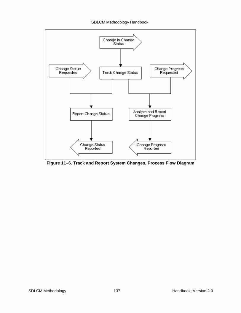
SDLCM Methodology Handbook
SDLCM Methodology 137 Handbook, Version 2.3
Figure 11–6. Track and Report System Changes, Process Flow Diagram

SDLCM Methodology Handbook
SDLCM Methodology 138 Handbook, Version 2.3
Figure 11–7. Track and Report System Changes, Data Flow Diagram
Table 11–3 associates the three activities with the roles responsible for their execution.
Table 11–3. Track and Report System Changes, Activity-Role MatrixActivities Roles
Accountable for Execution: Overall Project Manager,Technical Project Manager, Development Team
Approval to Proceed: Business Advocate
Provides Input: Business SME, Technical SME, OtherRepresentatives or Stakeholders: CM, QA
OP
M
T
P
M
D
T
B
A
B
S
M
E
T
S
M
E
OT
H
E
R
C
M
QA
1. Track change status. P
2. Report change status. P
3. Analyze and report change progress. P R
Legend: P = Performs, R = Reviews, A = Approves, S = Supports

SDLCM Methodology Handbook
SDLCM Methodology 139 Handbook, Version 2.3
11.3 Release Management
The purpose of this group of activities is to manage a releasefrom the time it has been defined through its deployment. It doesnot include the initial allocation of change packages to a release.Release Management includes four major activities:
� Plan Release
� Coordinate Release Changes
� Track Release Changes
� Track Releases
The following four subsections discuss the steps involved in the Release Management activitiesand the roles and products associated with those activities.
11.3.1 Plan Release
The purpose of this activity is to plan the release from an engineering point of view, as opposedto a Project management point of view. It verifies the means for development coordination andestablishes the structures for managing the components being created or modified by therelease.
A defined release triggers this activity as shown in the process flow diagram (see Figure 11–8).There are seven lower level activities:
1. Verify Development Coordination. Verify that a development coordination capabilityexists to coordinate all teams involved in the release and to coordinate the releaseactivities with the larger enterprise. This activity ensures that the organizations,responsibilities, capabilities, working relationships, policies, procedures, andinfrastructure exists to provide adequate coordination.
2. Establish Configuration Management. Verify and if necessary establish configurationmanagement for the release. Configuration management procedures, tools, andstandards should already exist for an application system that is under maintenance, butthey should be confirmed. Other configuration management planning is required foreach new release.
3. Review or Establish Standards. Review all applicable standards to be sure they areadequate for the Project and to create additional standards if needed. Include standardsfor both products and management documents. Confirm how the standards will beenforced.
4. Review or Establish Common Services. The purpose of this activity is to plan forreuse or sharing of components. Review existing reuse policies or establish policies onreuse. Establish what common services are included within the scope of the release,what new common services are required, and what new common services might becontributed from existing components within the scope of the release.
5. Plan Release Development and Define Work Packages. Plan how the release shouldbe developed. Divide the release into loosely coupled work packages that can beworked on by separate teams. Scope the work packages to minimize conflicts and
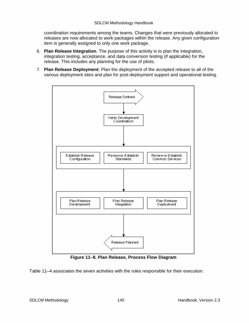
SDLCM Methodology Handbook
SDLCM Methodology 140 Handbook, Version 2.3
Figure 11–8. Plan Release, Process Flow Diagram
coordination requirements among the teams. Changes that were previously allocated toreleases are now allocated to work packages within the release. Any given configurationitem is generally assigned to only one work package.
6. Plan Release Integration. The purpose of this activity is to plan the integration,integration testing, acceptance, and data conversion testing (if applicable) for therelease. This includes any planning for the use of pilots.
7. Plan Release Deployment. Plan the deployment of the accepted release to all of thevarious deployment sites and plan for post-deployment support and operational testing.
Table 11–4 associates the seven activities with the roles responsible for their execution.
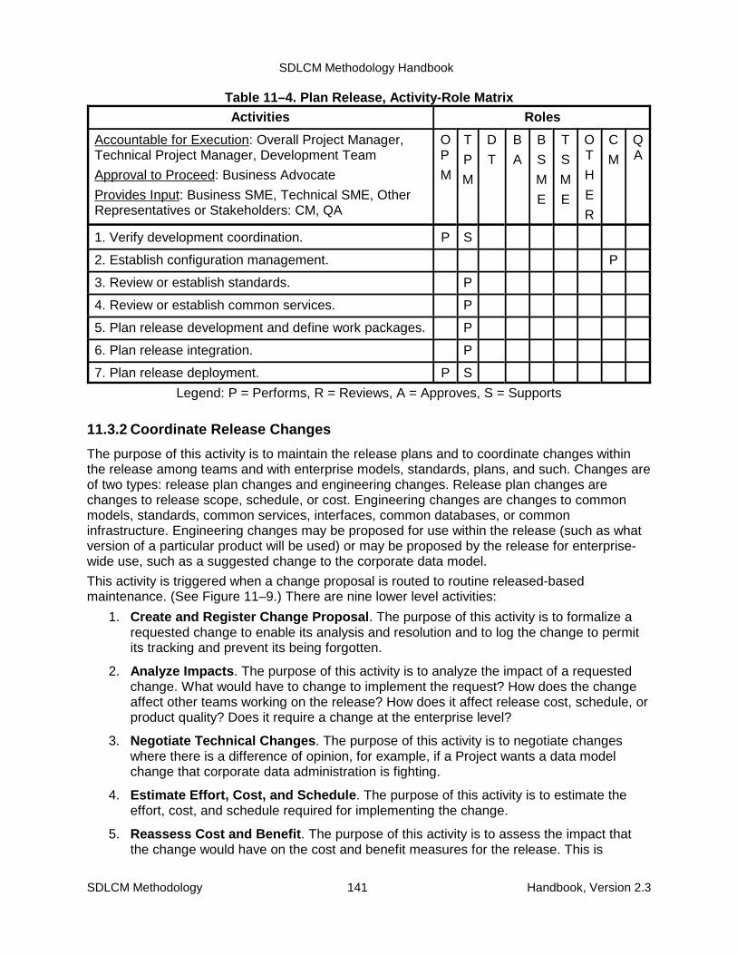
SDLCM Methodology Handbook
SDLCM Methodology 141 Handbook, Version 2.3
Table 11–4. Plan Release, Activity-Role MatrixActivities Roles
Accountable for Execution: Overall Project Manager,Technical Project Manager, Development Team
Approval to Proceed: Business Advocate
Provides Input: Business SME, Technical SME, OtherRepresentatives or Stakeholders: CM, QA
OP
M
T
P
M
D
T
B
A
B
S
M
E
T
S
M
E
OT
H
E
R
C
M
QA
1. Verify development coordination. P S
2. Establish configuration management. P
3. Review or establish standards. P
4. Review or establish common services. P
5. Plan release development and define work packages. P
6. Plan release integration. P
7. Plan release deployment. P S
Legend: P = Performs, R = Reviews, A = Approves, S = Supports
11.3.2 Coordinate Release Changes
The purpose of this activity is to maintain the release plans and to coordinate changes withinthe release among teams and with enterprise models, standards, plans, and such. Changes areof two types: release plan changes and engineering changes. Release plan changes arechanges to release scope, schedule, or cost. Engineering changes are changes to commonmodels, standards, common services, interfaces, common databases, or commoninfrastructure. Engineering changes may be proposed for use within the release (such as whatversion of a particular product will be used) or may be proposed by the release for enterprise-wide use, such as a suggested change to the corporate data model.
This activity is triggered when a change proposal is routed to routine released-basedmaintenance. (See Figure 11–9.) There are nine lower level activities:
1. Create and Register Change Proposal. The purpose of this activity is to formalize arequested change to enable its analysis and resolution and to log the change to permitits tracking and prevent its being forgotten.
2. Analyze Impacts. The purpose of this activity is to analyze the impact of a requestedchange. What would have to change to implement the request? How does the changeaffect other teams working on the release? How does it affect release cost, schedule, orproduct quality? Does it require a change at the enterprise level?
3. Negotiate Technical Changes. The purpose of this activity is to negotiate changeswhere there is a difference of opinion, for example, if a Project wants a data modelchange that corporate data administration is fighting.
4. Estimate Effort, Cost, and Schedule. The purpose of this activity is to estimate theeffort, cost, and schedule required for implementing the change.
5. Reassess Cost and Benefit. The purpose of this activity is to assess the impact thatthe change would have on the cost and benefit measures for the release. This is
SDLCM Methodology Handbook
SDLCM Methodology 142 Handbook, Version 2.3
intended to provide enough information for the CCB to make a business decision on theproposed change. This activity is performed only if there is an impact on release cost,schedule, or content. Many engineering changes will not affect cost, schedule, orcontent and thus will not require CCB review.
6. Package Requests for CCB Review. The purpose of this activity is to prepare theChange Proposals for presentation to the CCB. Present the facts and required decisionsclearly and concisely. Present the questions in order of their importance.
7. Negotiate and Approve Release Changes. The purpose of this activity is to negotiatechanges to the release plans. Such changes might include a slippage of the date topreserve content or a removal of content to preserve the date.
8. Implement Changes to Plans. The purpose of this activity is to implement the agreed-upon changes to the various plans, including plans at the enterprise, release, andProject levels. The result should be a consistent set of plans.
9. Implement Engineering Changes. The purpose of this activity is to implement theagreed-upon changes to the various common engineering documents and components.These include changes to models, standards, common services, interfaces, databases,and infrastructure at the individual, team, Project, release, and enterprise levels. Theresults should be a consistent set of engineering documents and shared components.

SDLCM Methodology Handbook
SDLCM Methodology 143 Handbook, Version 2.3
Figure 11–9. Coordinate Release Changes, Process Flow Diagram
Table 11–5 associates the nine activities with the roles responsible for their execution.

SDLCM Methodology Handbook
SDLCM Methodology 144 Handbook, Version 2.3
Table 11–5. Coordinate Release Changes, Activity-Role MatrixActivities Roles
Accountable for Execution: Overall Project Manager,Technical Project Manager, Development Team
Approval to Proceed: Business Advocate
Provides Input: Business SME, Technical SME, OtherRepresentatives or Stakeholders: CM, QA
OP
M
T
P
M
D
T
B
A
B
S
M
E
T
S
M
E
OT
H
E
R
C
M
QA
1. Create and register change proposal. P
2. Analyze impacts. R P
3. Negotiate technical changes. P P P
4. Estimate effort, cost, and schedule. P S
5. Reassess cost and benefit. P P
6. Package requests for CCB review. P S R
7. Negotiate and approve release changes. P P
8. Implement changes to plans. P
9. Implement engineering changes. P
Legend: P = Performs, R = Reviews, A = Approves, S = Supports
11.3.3 Track Release Changes
The purpose of this activity is to track and report changes in the status or change proposals andto assess the overall progress in addressing change proposals.
This activity is triggered when a change proposal changes status or there is a request to reportstatus or progress of changes. (See Figure 11–10.) There are three lower level activities:
1. Track Change Status. The purpose of this activity is to monitor change proposal activityto identify changes in change proposal status (either directly as an individual ChangeProposal or indirectly through association with a change package or release). Thisupdates the Change Log from which the status of individual changes can be obtainedand trends analyzed. The Change Report and Change Log for these changes can bethe same as used for changes requested for existing systems.
2. Report Change Status. The purpose of this activity is to report the status of individualchanges upon request.
3. Analyze and Report Change Progress. The purpose of this activity is to analyze andreport trends in the process of addressing change proposals. This will show whether thebacklog is growing or shrinking, among other things.

SDLCM Methodology Handbook
SDLCM Methodology 145 Handbook, Version 2.3
Change in ChangeStatus
Track Change Status
Report Change Status Analyze and ReportChange Progress
Change ProgressReported
Change StatusReported
Change StatusRequested
Change ProgressRequested
Figure 11–10. Track Release Changes, Process Flow Diagram
Table 11–6 associates the three activities with the roles responsible for their execution.
Table 11–6. Track Release Changes, Activity-Role MatrixActivities Roles
Accountable for Execution: Overall Project Manager,Technical Project Manager, Development Team
Approval to Proceed: Business Advocate
Provides Input: Business SME, Technical SME, OtherRepresentatives or Stakeholders: CM, QA
OP
M
T
P
M
D
T
B
A
B
S
M
E
T
S
M
E
OT
H
E
R
C
M
QA
1. Track change status P
2. Report change status P S
3. Analyze and report change progress P R
Legend: P = Performs, R = Reviews, A = Approves, S = Supports
SDLCM Methodology Handbook
SDLCM Methodology 146 Handbook, Version 2.3
11.3.4 Track Releases
The purpose of this activity is to track the status and progress of releases. It is fed by theProject status reporting from the Project management processes. A Project can span severalreleases, and a release can span several Projects. The primary information monitored is theestimated completion date and the estimated cost at completion for the release. This is neededto be able to report the expected deployment dates for changes being implemented by therelease. (There may also be intermediate milestones defined for the release, but these aremore important for Project management and program assurance than for changemanagement.)
This activity is triggered when a release changes status or there is a request to report status orprogress of changes. (See Figure 11–11.) There are three lower level activities:
1. Track Release Status. The purpose of this activity is to monitor the planned cost,schedule, and content of the release as it changes based on agreed-upon requestedchanges and actual events. At any point in time, you should be able to identify theProjected completion date, the Projected cost, and the planned content of the release(that is, which change packages are included).
2. Report Release Status. The purpose of this activity is to report, upon request or regularschedule, the Projected completion date, the Projected cost, and the planned content ofthe release.
3. Analyze and Report Release Progress. The purpose of this activity is to report, uponrequest or regular schedule, any information showing rates of progress. This might bestated in terms of earned value if this approach has been implemented.

SDLCM Methodology Handbook
SDLCM Methodology 147 Handbook, Version 2.3
Change in ReleaseStatus
Track Release Status
Report Release Status Analyze and ReportRelease Progress
Release ProgressReported
Release StatusReported
Release StatusRequested
Release ProgressRequested
Figure 11–11. Track Releases, Process Flow Diagram
Table 11–7 associates the three activities with the roles responsible for their execution.
Table 11–7. Track Releases, Activity-Role MatrixActivities Roles
Accountable for Execution: Overall Project Manager,Technical Project Manager, Development Team
Approval to Proceed: Business Advocate
Provides Input: Business SME, Technical SME, OtherRepresentatives or Stakeholders: CM, QA
OP
M
T
P
M
D
T
B
A
B
S
M
E
T
S
M
E
OT
H
E
R
C
M
QA
1. Track release status. P
2. Report release status. P S
3. Analyze and report release progress. P R

SDLCM Methodology Handbook
SDLCM Methodology 148 Handbook, Version 2.3
Legend: P = Performs, R = Reviews, A = Approves, S = Supports
11.4 Release-Based Maintenance
The Routine Maintenance process addresses maintaining andevolving existing systems. It focuses on making changes to anexisting environment, taking the operational system and itsinfrastructure as constraints: the changes have to be built onthe underlying structure and have to be compatible with theexisting system architecture.
There are four types of changes:
� Corrective changes
� Adaptive changes
� Perfective changes
� Preventive changes
Routine Maintenance may be performed continually and in parallel with other developmentpaths. Triggers and results are shown in the process flow diagram (see Figure 11–12). Thedata flow diagrams (see Figure 11–13 and Figure 11–14) illustrates the flow of data among theeighteen lower level activities:
1. Determine Type of Change. Understand the reason for the change in order todetermine the type of change. The type of change information helps you to select theappropriate sequence of activities and their level of detail. Do this for each changecontained in the Work Package. This activity starts the Release-Based MaintenanceProcess and is usually performed after a Work Package has been received. This activitywill be completed when each change has been classified as corrective or non-corrective(that is, adaptive, perfective, preventive). Group changes into sets of related changes.
2. Extend Requirement Analysis. Extend the Requirements Analysis to understand theneed that caused the Change Proposal. Refine to a more detailed level to produce inputfor subsequent design activities.
3. Extend Problem Analysis. Refine the initial Problem Analysis that was done afterreceiving the Problem Report until you can identify the underlying cause. Keep in mindthat the results of this activity will be the basis for designing the change.
4. Extend Existing System Analysis. Create, refine, or update the model views orequivalent system documentation needed for System Evolution and Maintenance. Keepin mind that the results of this activity will be needed for designing the change. Thisactivity may be invoked and performed in parallel to ongoing work when additional, new,or more detailed information is needed. This may happen as a result of a change insystem functionality or configuration or during Problem or Requirement Analysis.
5. Design Change at High-Level. Work out a high-level design for implementing thechange. Focus on the logical level of the programs, the interaction among them or thedata entities if the changes are in that area. The results of this activity will be the basisfor the implementation of the change. Try to keep the design compatible and alignedwith the existing architecture and operation.
6. Review High-Level Design. Review the High-level Design for the change. Validate that
SDLCM Methodology Handbook
SDLCM Methodology 149 Handbook, Version 2.3
the design basically adheres to the current architecture and its use and that necessarychanges are compatible to them. Approve or update related estimates for resources,schedule, and costs.
7. Reassess Impact. Reassess the impact of the change in the context of the currentsystem and the modifications to be done. If necessary, refine the Impact Analysis inorder to get to a valid and agreed assessment of the consequences of the change.
This activity incrementally creates, updates, or refines information on the change’simpact upon the existing system architecture. It may be iterated. As Analysis proceedsor resumes, its scope may evolve from deeper to higher level of detail as well as fromrather limited to broader scope.
8. Decide Whether to Proceed. Decide whether to promote the change to theimplementation activity in the proposed way or to turn the change back forreconsideration. At this time, the impact of the change, the resources needed toimplement it, and both the schedule and costs estimates have been validated; and theydescribe the different aspects of the change correctly.
In the case the change is turned back, there are two choices:
(1) Create a different design by repeating the prior steps beginning with “Design Changeat High-Level” or
(2) Raise an issue and send the change to back to the Change Management process.
9. Implement Change. The following paragraphs describe the activity “ImplementChange” in a generalized way that can be tailored to different development approaches.
Implementation is a composite activity that can vary greatly in size and complexity givena particular problem set, environment, and development approach. However, regardlessof the specific development approach chosen, implementation is made of three kinds ofbasic activities: design, construction, and validation (or design, code, test). The basicimplementation approaches are constructed by wiring together these activities indifferent sequences and iterations, for different units of scope and time, in differenttechnical environments, and with different human dynamics:
One option is an iterative learning approach, designing the business process changeand then deriving the system change, going through several cycles of design, code, andvalidate, that allow for learning during the development process and uncovering hiddenneeds.
Another option is an accelerated approach, going through several tightly scheduled timeboxes consisting of design, code, validate in a lab environment, with functionality madesecondary to schedule.
Another option is an incremental waterfall approach, with larger chunks of design, code,and validate, but with greater emphasis of formal validation of requirements and design.
Another option is a package-based approach, with requirements transmuting intoselection criteria and selection becoming part of the design activity (as in adding aCOTS module onto an existing application).
If prototyping is used, go through several iterations of design, construction, andvalidation of a prototype as a means to discover hidden requirements and to arrive at adesign for the target system.

SDLCM Methodology Handbook
SDLCM Methodology 150 Handbook, Version 2.3
After the prototyping stage is complete, the coding stage completes the armor-platingprocess if a limited function prototype is being evolved into the target system; but if onlysimulation prototyping was used, the coding stages is the construction of the targetsystem in the target environment.
If a package-based approach is selected, understand Design as to include packageselection as well.
If a requirements-driven approach is selected, create the Design by use of theRequirement Analysis Technique and iteration to more detailed level.
To assemble an implementation approach, take the basic building blocks, apply tailoringto the specific context, scope, and level of detail, and iterate as needed to cover thewhole change. This will provide an implementation path that is tailored to the changeand the constraints of the existing environment and satisfies the preferences of thecustomer.
Start each path variant with an enabling activity that establishes the prerequisites inorder to perform the implementation activities.
There are four steps for implementing a change:
� Prepare for Implementation. Establish or validate the prerequisites that are neededfor implementing the change. Include both technical and organizational aspects tobe able to continue work with designing the next level of detail of the change.
� Design Change detailed. Refine the High-Level Design of the change down to theUnit or Module level. The goal of this activity is to develop a physical design forprograms and the referenced data so that coding can start. Several iterations maybe necessary until this level of detail will be reached.
� Code the Change. Code the change on the basis of the detailed design that hasbeen created before. In parallel to this work, create Test Cases for testing codesections during implementation and later for Unit Testing.
� Short-Test Code (optional). Perform some short tests on selected code sections toget confirmation that the changed modules will basically work and are mature forentering Unit Testing. Short Testing may help to detect obvious implementation orunit design errors very early. The test takes place in the Personal Library. Proceedwith coding on the next change item after successful Short test.
10. Unit Test Change. When the Implementation has been completed, test the new orchanged functions to make sure that they satisfy the requirements and needs describedin the Change Proposal or Problem Report. Within Unit Test, focus on the functionalityof the change.
11. Consolidate Changes of Work Package. Integrate all modules related to the changesof the Work Package with the unchanged modules of the application to be able toperform the Work Package Integration Test.
12. Perform Work Package Integration Test. After having integrated all changes of aWork Package, test the new or modified functions of the entire Change Package. Withinthis test, focus on the communication and interaction between the changes of the WorkPackage when using the these functions.
13. Perform Regression Test on Application. Perform Regression Testing on Application

SDLCM Methodology Handbook
SDLCM Methodology 151 Handbook, Version 2.3
level to ensure that functionality that should persist has not been affected by the new ormodified functions introduced with the Change Package.
14. Integrate Release. Integrate all Work Packages of the Release with the remainingunchanged modules of the Release. This activity links together the non-modifiedcomponents with the new or changes module for the first time. It prepares Integrationand Regression Testing for the entire Release.
15. Test the Release. After the release has been integrated, this activity determines if theexisting parts of the release harmonize with new functionality introduced by the WorkPackages. Within this test, focus on the interaction of the subsystems or majorcomponents of the system or release when using the new functions.
16. Perform Regression Test on Release. Perform Regression Testing on Release levelto ensure that the existing functionality of the Release has not been affected by the newor modified functions introduced by the Change Packages.
17. Plan Testing (ongoing). Test Planning is an ongoing activity in which new informationis added to existing documents as it arises. It proceeds in parallel with the design andimplementation process, creating Test Cases as soon as they can be defined. Followthis approach if it is feasible.
18. Document Changes (ongoing). Document the change on its way through thedevelopment life cycle. This documentation is needed primarily for understanding thechange. It also helps to keep the system information up to date and correct.
Figure 11–13. Release-Based Maintenance, Data Flow Diagram (1 of 2)

SDLCM Methodology Handbook
SDLCM Methodology 152 Handbook, Version 2.3
1Determine Type of
Change
Item ofChange Package
sent back
Work Packagereceived
2Extend
Requirement Analysis
4 ExtendExisting System
Analysis
3Extend
Problem Analysis
4 ExtendExisting System
Analysis
Iterate until high-level Designis acceptable
Design Change atHigh-level
ReviewHigh-level Design
Reassess Impact
Decide whetherto Proceed
Implement Change
Unit Test Change
Consolidate Changesof Work Package
PerformWork PackageIntegration Test
PerformRegression Teston Application
Integrate Release
Test the Release
PerformRegression Test
on Release
all Work Packagesintegrated in
Release; ReleaseRegression testedWork Package
completed;Application
Regression tested
ONGOING ACTIVITIES
Plan Testing
Document Changes
5
6
7
8
9
10
11
12
13
14
15
16
17
18
Change itemaccepted
Change item notaccepted
Release Based MaintenanceProcess
(revised 2/14/97)Change is non-
correctiveChange iscorrective
End of SustainingEngineering
Figure 11–12. Release-Based Maintenance, Process Flow Diagram

SDLCM Methodology Handbook
SDLCM Methodology 153 Handbook, Version 2.3
Change Mgmt Work Package
ExtendRequirement
Analysis
Changes of aChange Request
ExtendProblemAnalysis
Changes of aProblem Report
ExtendExisting System
Analysis
SystemInformation
Design Changeat High-Level
ReviewHigh-Level
Design
Reassess Impact
High-Level Design andEstimates (approved )
High-Level Design
Decideweather to
ProceedChange Mgmt
RejectedChangeItems
Impact Analysis (revalidated)
Accepted Change Items
SystemInformation
SystemInformation
DetermineType of Change
UserComments
Draft
Release Based Maintenance
Data Flow Diagram of Release Based Maintenance(1)
Changes,Change Request
(updated)
Changes,Problem Report
(updated)
PlanTesting
Plans andProcedures
Test Plans
Work ProductsDocumentChange
Figure 11–13. Release-Based Maintenance, Data Flow Diagram (1 of 2)
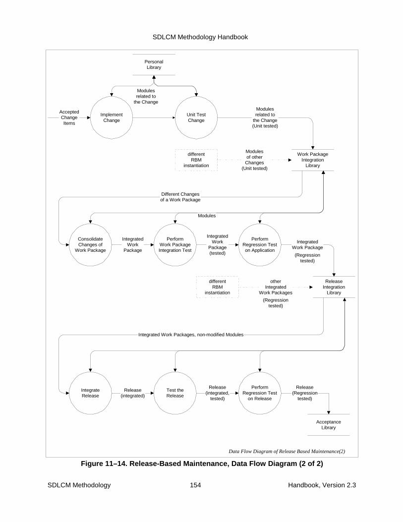
SDLCM Methodology Handbook
SDLCM Methodology 154 Handbook, Version 2.3
Unit TestChange
ConsolidateChanges of
Work Package
ImplementChange
Work PackageIntegration
Library
PersonalLibrary
PerformWork PackageIntegration Test
PerformRegression Teston Application
IntegrateRelease
Test theRelease
ReleaseIntegration
Library
Modulesrelated to
the Change(Unit tested)
Different Changesof a Work Package
Modules
AcceptedChangeItems
IntegratedWork
Package
IntegratedWork
Package(tested)
IntegratedWork Package
Integrated Work Packages, non-modified Modules
Release(integrated)
Release(integrated,
tested)
PerformRegression Test
on Release
differentRBM
instantiation
otherIntegrated
Work Packages
differentRBM
instantiation
Modulesof other
Changes(Unit tested)
Modulesrelated to
the Change
(Regressiontested)
(Regressiontested)
Data Flow Diagram of Release Based Maintenance(2)
AcceptanceLibrary
Release(Regression
tested)
Figure 11–14. Release-Based Maintenance, Data Flow Diagram (2 of 2)

SDLCM Methodology Handbook
SDLCM Methodology 155 Handbook, Version 2.3
Table 11–8 associates the 18 activities with the roles responsible for their execution.
Table 11–8. Release-Based Maintenance, Activity-Role MatrixActivities Roles
Accountable for Execution: Overall Project Manager,Technical Project Manager, Development Team
Approval to Proceed: Business Advocate
Provides Input: Business SME, Technical SME, OtherRepresentatives or Stakeholders: CM, QA
OP
M
T
P
M
D
T
B
A
B
S
M
E
T
S
M
E
OT
H
E
R
C
M
QA
1. Determine type of change. P
2. Extend requirement analysis. P
3. Extend problem analysis. P
4. Extend existing system analysis. P
5. Design change at high-level. P
6. Review high-level design. S P
7. Reassess impact. P
8. Decide whether to proceed. P
9. Implement change. P
10. Unit test change. P
11. Consolidate changes of work package. P
12. Perform work package integration test. P
13. Perform regression test on application. P
14. Integrate release. P
15. Test the release. P
16. Perform regression test on release. P
17. Plan testing (ongoing). P
18. Document changes (ongoing). P
Legend: P = Performs, R = Reviews, A = Approves, S = Supports
Figure 11–15 depicts the flow of a software module through the various software librariesduring the development, integration, testing, and deployment processes. The figure includesthe paths for both routine (release-based) maintenance and emergency maintenance(addressed in the next section).
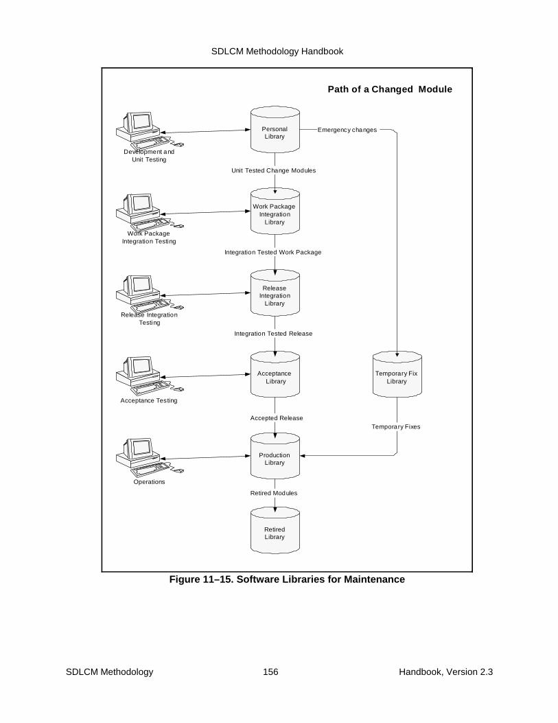
SDLCM Methodology Handbook
SDLCM Methodology 156 Handbook, Version 2.3
PersonalLibrary
ReleaseIntegration
Library
AcceptanceLibrary
Temporary FixLibrary
RetiredLibrary
ProductionLibrary
Integration Tested Release
Accepted Release
Development andUnit Testing
Retired Modules
Path of a Changed Module
Work PackageIntegration
Library
Integration Tested Work Package
Unit Tested Change Modules
Work PackageIntegration Testing
Release IntegrationTesting
Acceptance Testing
Operations
Emergency changes
Temporary Fixes
Figure 11–15. Software Libraries for Maintenance

SDLCM Methodology Handbook
SDLCM Methodology 157 Handbook, Version 2.3
11.5 Emergency Maintenance
Emergency Maintenance addresses maintenance required inemergency situations. An Emergency situation may arise duringsystem operation when system errors with severe impact occurand cannot be handled by the system administration. Such errorsmust be fixed as quickly as possible to return to operation.
After an emergency situation is fixed by an EmergencyMaintenance intervention, the related Problem Report isreconsidered by Change Management and fed into the queue ofpending changes to the system. Emergency Maintenance is oftena temporary fix to solve an urgent problem very quickly and normally is often not suitable as alasting change to the system. Thus, it should go into the short list of changes to be included inone of the next releases and then become a permanent and fully quality-assured change to thesystem.
To ensure consistent decisions with minimal delay, control of the Emergency Maintenanceactivities is concentrated in an Emergency Management role within Change Management.Emergency Management’s primary responsibility is to control the Emergency Maintenanceprocesses and to make the decisions effectively and very fast in an area where system andbusiness issues overlap. It also serves as the interface between Operations and the EmergencyMaintenance Team. Emergency Management may consist of only one experienced individualwith sound knowledge in both the systems and business worlds. Alternatively, there might betwo individuals acting as an efficient team.
It is vital for performing Operations and Emergency Maintenance effectively that information onthe system is available and reliable. If such information is not yet available, apply analyze theexisting system to establish at least the minimum set of required documentation or refine theexisting information if there are gaps before the first emergency situation occurs.
Figure 11–16 gives a high level overview of how Emergency Maintenance fits into the overallcycle of system maintenance and operation. The boxes represent process groups, the arrowsthe flow of the indicated work products. The figure illustrates the following:
� During Operation, an emergency situation occurs. After a first diagnosis, aProblem Report is sent to Emergency Management.
� Emergency Management assesses the gravity of the problem, different solutionapproaches, and decides whether an Emergency Maintenance Intervention isneeded.
� If it is an instance for Emergency Maintenance, Emergency Management sendsthe Problem Report to the Emergency Maintenance Team.
� The Emergency Maintenance Team then works to solve the problem by work-arounds or adequate system changes (varies from patches to source codechanges).
� After a solution has been identified, implemented, and sufficiently tested, it is fedinto production environment.
� Emergency Management (within Change Management) receives the updatedProblem Report and documentation on the emergency fix and then decides

SDLCM Methodology Handbook
SDLCM Methodology 158 Handbook, Version 2.3
Emergency Maintenance
ScheduledRelease
-- Changes due to RBM-- Changes due to EMM
Change/Problem LogProblem Report/Change Request
-- Changes due to RBM-- Changes due to EMM
Release Plan
Change Management
EmergencyMgmt
Operation
Help Desk
Problem Report /Change Request
EmergencyMaintenance
Release /Accepted
System Build
Emergency Fix
Problem Report /Change Request
Selected ChangesAssigned to
Future Releases
Candidate Changes forFuture Releases
DevelopmentCoordination
Release BasedMaintenance
Integrationand
Deployment
Work Package(s)
Release /System Build
Figure 11–16. Emergency Maintenance in Context
whether the change will be promoted into the queue of candidate changes forfuture releases.
� Emergency Management is responsible that Emergency Maintenanceinterventions are tracked and reported to Operations and Change Management.
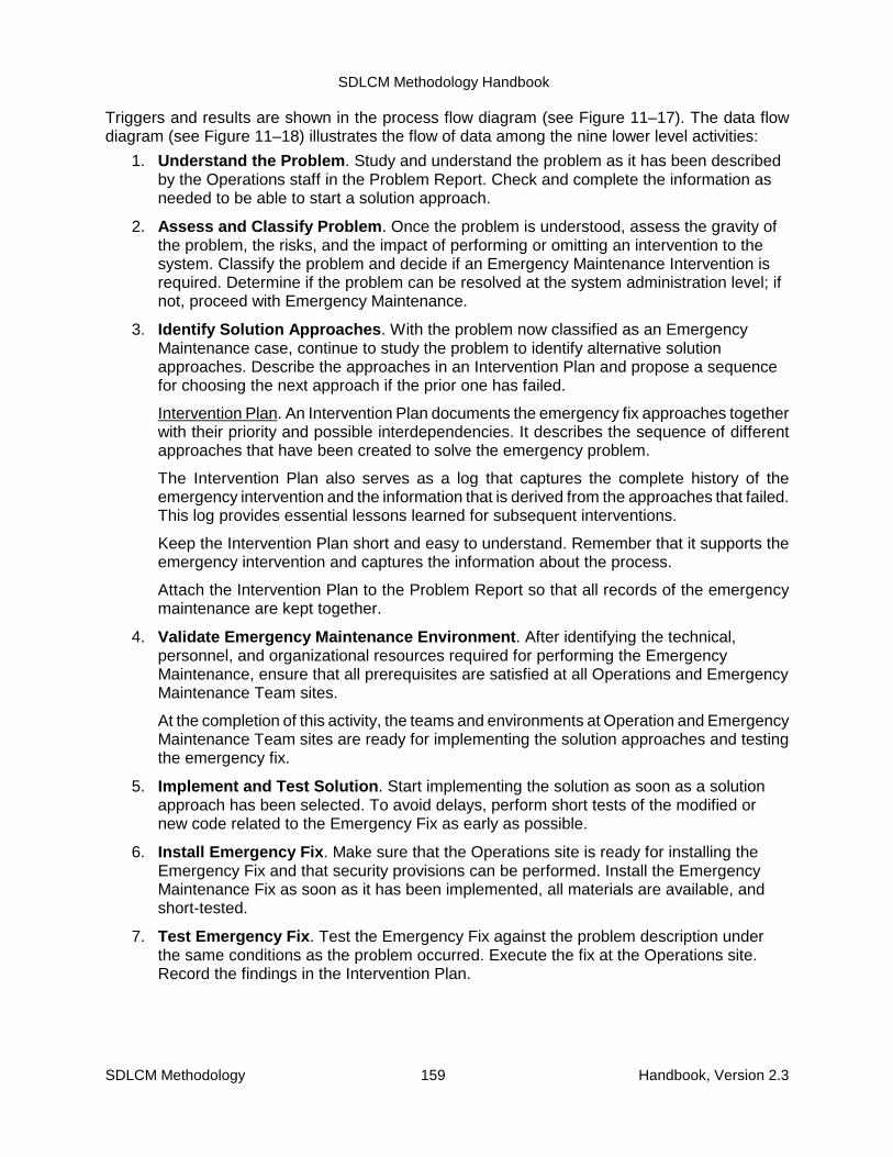
SDLCM Methodology Handbook
SDLCM Methodology 159 Handbook, Version 2.3
Triggers and results are shown in the process flow diagram (see Figure 11–17). The data flowdiagram (see Figure 11–18) illustrates the flow of data among the nine lower level activities:
1. Understand the Problem. Study and understand the problem as it has been describedby the Operations staff in the Problem Report. Check and complete the information asneeded to be able to start a solution approach.
2. Assess and Classify Problem. Once the problem is understood, assess the gravity ofthe problem, the risks, and the impact of performing or omitting an intervention to thesystem. Classify the problem and decide if an Emergency Maintenance Intervention isrequired. Determine if the problem can be resolved at the system administration level; ifnot, proceed with Emergency Maintenance.
3. Identify Solution Approaches. With the problem now classified as an EmergencyMaintenance case, continue to study the problem to identify alternative solutionapproaches. Describe the approaches in an Intervention Plan and propose a sequencefor choosing the next approach if the prior one has failed.
Intervention Plan. An Intervention Plan documents the emergency fix approaches togetherwith their priority and possible interdependencies. It describes the sequence of differentapproaches that have been created to solve the emergency problem.
The Intervention Plan also serves as a log that captures the complete history of theemergency intervention and the information that is derived from the approaches that failed.This log provides essential lessons learned for subsequent interventions.
Keep the Intervention Plan short and easy to understand. Remember that it supports theemergency intervention and captures the information about the process.
Attach the Intervention Plan to the Problem Report so that all records of the emergencymaintenance are kept together.
4. Validate Emergency Maintenance Environment. After identifying the technical,personnel, and organizational resources required for performing the EmergencyMaintenance, ensure that all prerequisites are satisfied at all Operations and EmergencyMaintenance Team sites.
At the completion of this activity, the teams and environments at Operation and EmergencyMaintenance Team sites are ready for implementing the solution approaches and testingthe emergency fix.
5. Implement and Test Solution. Start implementing the solution as soon as a solutionapproach has been selected. To avoid delays, perform short tests of the modified ornew code related to the Emergency Fix as early as possible.
6. Install Emergency Fix. Make sure that the Operations site is ready for installing theEmergency Fix and that security provisions can be performed. Install the EmergencyMaintenance Fix as soon as it has been implemented, all materials are available, andshort-tested.
7. Test Emergency Fix. Test the Emergency Fix against the problem description underthe same conditions as the problem occurred. Execute the fix at the Operations site.Record the findings in the Intervention Plan.
SDLCM Methodology Handbook
SDLCM Methodology 160 Handbook, Version 2.3
8. Evaluate Results of Approach. After the Fix has been tested, evaluate the results ofthe solution approach for the emergency problem to decide if the Emergency Fix solvesthe problem sufficiently or if another approach must be taken.
9. Reassess Emergency Problem and Fix. After the emergency situation has beenresolved, reassess both the problem that caused that emergency and the EmergencyFix. Include both system and business aspects in the assessment. Transfer theEmergency Fix into a Change Proposal and pass it to the Change Management if this isappropriate. The Fix will then be replaced by a release-based change in a later release.
Emergency fixes are done under severe time restrictions, with the focus on getting thesystem to operation as quick as possible and not on the quality aspects that apply toregular system evolution as done by Release-Based Maintenance. Furthermore, emergencyfixes might be done as patches to run-time modules and not traced back to the source codemodules after the system is running again. This situation may cause increasedmaintenance efforts, and increase the risk of losing the fix in a subsequent system orreleases.
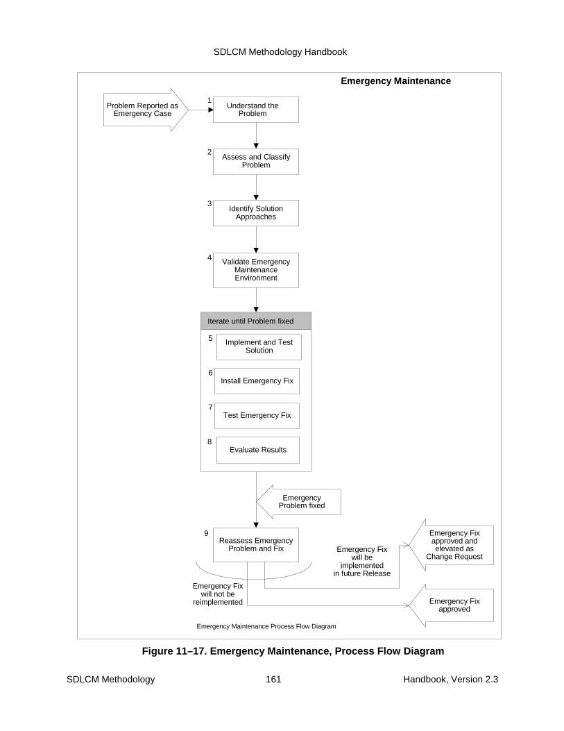
SDLCM Methodology Handbook
SDLCM Methodology 161 Handbook, Version 2.3
Understand theProblem
EmergencyProblem fixed
Problem Reported asEmergency Case
1
Assess and ClassifyProblem
Identify SolutionApproaches
Validate EmergencyMaintenanceEnvironment
14
Iterate until Problem fixed
Install Emergency Fix
Test Emergency Fix
5
6
7
Implement and TestSolution
Evaluate Results
Reassess EmergencyProblem and Fix
Emergency Fixapproved andelevated as
Change Request
Emergency Fixapproved
2
3
4
8
Emergency Fixwill not be
reimplemented
Emergency Fixwill be
implementedin future Release
9
Emergency Maintenance Process Flow Diagram
Emergency Maintenance
Figure 11–17. Emergency Maintenance, Process Flow Diagram

SDLCM Methodology Handbook
SDLCM Methodology 162 Handbook, Version 2.3
Operations
Understandthe Problem
Comments,Information
Emergency Maintenance
Data Flow Diagram of Emergency Maintenance
Assessand Classify
ProblemIdentifySolution
Approaches
ValidateEmergency
MaintenanceEnvironment
Implementand TestSolution
InstallEmergency Fix
Emergency Case,Problem Report
TestEmergency
Fix
EvaluateResults
ReassessEmergency
Problemand Fix
ProblemReport
(updated)
InterventionPlan
SolutionApproachesIntervention
Plan
Solution Approaches,Intervention Plan
Changesrelated toSolution,
InterventionPlan
UpdatedSystem
InterventionPlan
Results, Intervention Plan,Problem Report
if EmergencyProblem
if other Solution
found
Solution
ChangeBacklog
ProblemReport
(updated)
System /Operations
Documentation
InterventionPlan, Change
Documentation
Operations
ChangeManagement
System
Note:Emergency Managemt is
part of the Process
Intervention Plancaptures all recordson the EmergencyFix and the work
during the process
Figure 11–18. Emergency Maintenance, Data Flow Diagram
Table 11–9 associates the nine activities with the roles responsible for their execution.
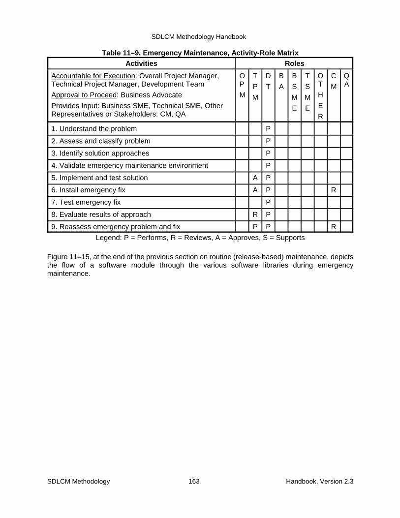
SDLCM Methodology Handbook
SDLCM Methodology 163 Handbook, Version 2.3
Table 11–9. Emergency Maintenance, Activity-Role MatrixActivities Roles
Accountable for Execution: Overall Project Manager,Technical Project Manager, Development Team
Approval to Proceed: Business Advocate
Provides Input: Business SME, Technical SME, OtherRepresentatives or Stakeholders: CM, QA
OP
M
T
P
M
D
T
B
A
B
S
M
E
T
S
M
E
OT
H
E
R
C
M
QA
1. Understand the problem P
2. Assess and classify problem P
3. Identify solution approaches P
4. Validate emergency maintenance environment P
5. Implement and test solution A P
6. Install emergency fix A P R
7. Test emergency fix P
8. Evaluate results of approach R P
9. Reassess emergency problem and fix P P R
Legend: P = Performs, R = Reviews, A = Approves, S = Supports
Figure 11–15, at the end of the previous section on routine (release-based) maintenance, depictsthe flow of a software module through the various software libraries during emergencymaintenance.
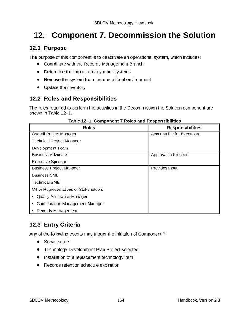
SDLCM Methodology Handbook
SDLCM Methodology 164 Handbook, Version 2.3
12. Component 7. Decommission the Solution12.1 Purpose
The purpose of this component is to deactivate an operational system, which includes:
� Coordinate with the Records Management Branch
� Determine the impact on any other systems
� Remove the system from the operational environment
� Update the inventory
12.2 Roles and Responsibilities
The roles required to perform the activities in the Decommission the Solution component areshown in Table 12–1.
Table 12–1. Component 7 Roles and ResponsibilitiesRoles Responsibilities
Overall Project Manager
Technical Project Manager
Development Team
Accountable for Execution
Business Advocate
Executive Sponsor
Approval to Proceed
Business Project Manager
Business SME
Technical SME
Other Representatives or Stakeholders
• Quality Assurance Manager
• Configuration Management Manager
• Records Management
Provides Input
12.3 Entry Criteria
Any of the following events may trigger the initiation of Component 7:
� Service date
� Technology Development Plan Project selected
� Installation of a replacement technology item
� Records retention schedule expiration

SDLCM Methodology Handbook
SDLCM Methodology 165 Handbook, Version 2.3
12.4 Input, Activities, and Outputs
The inputs to this component are as follows:
� Project Management Plan
� Software Engineering Notebook
� Installed solution
� Operational Environment
� System Inventory
� Technical Reference Model
� GILS
Figure 12–1 illustrates the flow of the following activities:
1. Review and update plans and announce decommissioning:
2. Notify Records Management Branch to review records management requirements
3. Analyze system interfaces and document effect on any other systems
4. Obtain approval to remove the solution from the operational environment
5. Update documentation and records
6. Wait for confirmation and remove the system
7. Obtain final sign-off that decommissioning is complete
As the figure suggests, many of the activities can be performed in parallel. The activities aredescribed in more detail in Section 12.7.
Figure 12–1 also summarizes the outputs of all Component 7 activities in the central data store.
Appendix C includes a summary description of all products of NRC Projects, indicates within whichcomponents each product is created and updated, and specifies which products are required.
The products, whose standard and form numbers are shown in the figure, are described inmore detail in the companion volume SDLCM Methodology Procedures, Standards, and Forms.
12.5 Techniques and Tools
The activities of Component 7 are supported by the following techniques:
� Structured Facilitation
� Structured Walkthrough
� Peer Review
Refer to the current SDLCM Methodology Tool Inventory for the recommended set of tools.

SDLCM Methodology Handbook
SDLCM Methodology 166 Handbook, Version 2.3
Project Action Plan (PAP), S-1052Software Engineering Notebook (SEN), S-3091Enterprise Model Change Request Form, F-2070System Inventory Update Form, F-2071Technical Reference Model Update Form, F-2073Problem Report Form, F-2251Problem Report Log Form, F-2252Government Information Locator System (GILS) Update Form, F-3060Records Retention and Disposition Authority, NRC Form 331Request for Records Disposition Authority, SF 115Go or No Go Decision for Project Form, Component 7, F-1157
7.1 Review andUpdate Plans and
AnnounceDecommissioning
7.2 NotifyRecords
ManagementBranch to review
RecordsManagementrequirements
7.3 Analyzesystem interfaces
and documenteffect on anyother systems
7.5 Updatedocumentation
and records
7.7 Obtain finalsign-off that
decommissioningis complete
Project Library fromprevious Components
PAP
7.6 Wait forconfirmation and
remove the system
7.4 Obtainapproval toremove the
solution from theoperational
environment
DecommissioningAnnouncement
SEN
F-2251F-2252
F-1157
F-1157
PAP
F-1157 (complete)
NRC Form 331
SF 115F-2070F-2071F-2073F-3060
SEN
Figure 12–1. Component 7

SDLCM Methodology Handbook
SDLCM Methodology 167 Handbook, Version 2.3
12.6 Exit Criteria
Component 7 is complete when:
� All critical products have been reviewed (structured walkthrough or peer review)
� Key products have been inspected by QA to conform to Project standards
� Products have been placed under CM control
� Information has been shared
� Issues have been resolved
� There is management approval that the decommissioning is complete
12.7 Component 7 Activity Details
The following pages provide detailed activities of Component 7, Decommission the Solution.

SDLCM Methodology Handbook
SDLCM Methodology 168 Handbook, Version 2.3
ProjectAction Plan
DeploymentAnnounce-
ment
CreateAnnounce-
ment
Awareness
AnnounceDeployment
Schedule
Determinewhat to do
with system
UpdatedPAP
Update thePAP
Figure 12–2. Review and Update Plans and Announce Decommissioning
Activity 7.1: Review and Update Plans and Announce Decommissioning
See Figure 12–2.
� Review the Project Management Plan, and announce the decommissioning to the entireNRC community. It is important to prepare people to expect decommissioning activities.The system may have users of whom the owner is unaware.
� From the users’ point of view, determine what will be done with the software, data, anddocumentation of the decommissioned system (for example, leave it in the inventory forpossible future use, turn it over to a different organization, save it for a specified timeperiod, destroy it). (Analysis of the legal and regulatory Records Managementrequirements may necessitate alternative disposition of the system.)
� Update the Project Management Plan.

SDLCM Methodology Handbook
SDLCM Methodology 169 Handbook, Version 2.3
Activity 7.2: Notify Records Management Branch to Review Records ManagementRequirements
See Figure 12–3.
1. Review copies of the previously submitted Records Management forms in the Projectlibrary:
� Information System Description, NA Form 14028
� Records Retention and Disposition Authority, NRC Form 331
� Notification of Electronic Information System Design or Modification, NRC Form 616
� Request for Records Disposition Authority, SF 115
2. Complete a new NRC Form 331 and deliver it to Records Management as notificationthat that an application system is about to be decommissioned.
3. After the form has been processed, combine the legal and regulatory requirements withthe business and technical requirements (documented in Activity 7.3) and update thedocumentation in Activity 7.5.

SDLCM Methodology Handbook
SDLCM Methodology 170 Handbook, Version 2.3
RecordsManagementRequirements
Review previousRecords
Managementforms
Records Retentionand Disposition
Authority, NRC Form331
Information SystemDescription, NA
Form 14028
Request for RecordsDisposition Authority,
SF 115
Notification of ElectrInfo Sys Design orModification, NRC
Form 616
Notify RecordsManagement thata system will bedecommissioned
Records Retentionand Disposition
Authority, NRC Form331
RecordsManagement
Branchprocesses form
Figure 12–3. Notify Records Management Branch to Review Records ManagementRequirements

SDLCM Methodology Handbook
SDLCM Methodology 171 Handbook, Version 2.3
Analyzeexternal
interfaces
SEN
Problem Reports(F-2251)
Problem Report Log(F-2252)
Figure 12–4. Analyze System Interfaces and Document Effect on Any Other Systems
Activity 7.3: Analyze System Interfaces and Document Effect on Any Other Systems
See Figure 12–4. Using information in the Software Engineering Notebook,
1. Analyze the system to determine any external interfaces or dependencies.
2. If other application systems make calls to functionality provided by this system or makeuse of any data generated by this system, submit Problem Report(s) using FormF–2251 to the CCBs of the affected systems to document the fact that thedependencies must be removed. (NOTE: It is the responsibility of the owners of theaffected systems to make the necessary changes or to request that thisdecommissioning activity be terminated. The decommissioning team must not initiateActivity 7.6 before receiving confirmation that all dependencies have been removed.)
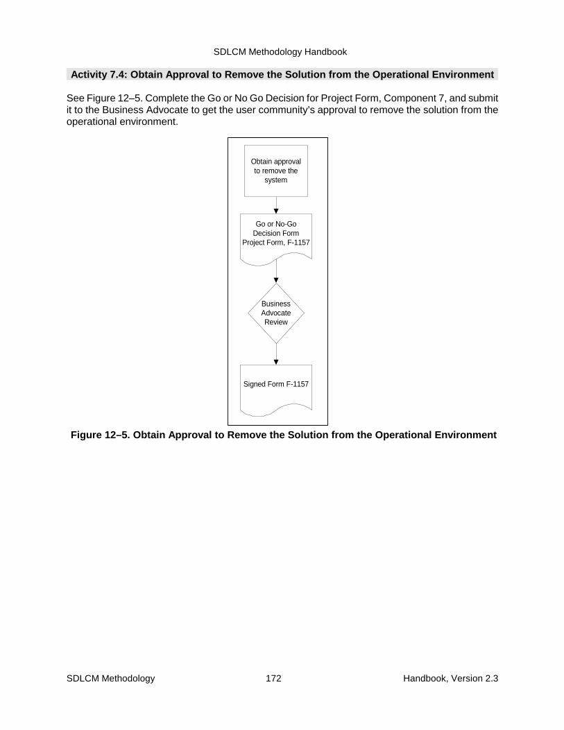
SDLCM Methodology Handbook
SDLCM Methodology 172 Handbook, Version 2.3
BusinessAdvocateReview
Go or No-GoDecision Form
Project Form, F-1157
Obtain approvalto remove the
system
Signed Form F-1157
Figure 12–5. Obtain Approval to Remove the Solution from the Operational Environment
Activity 7.4: Obtain Approval to Remove the Solution from the Operational Environment
See Figure 12–5. Complete the Go or No Go Decision for Project Form, Component 7, and submitit to the Business Advocate to get the user community’s approval to remove the solution from theoperational environment.
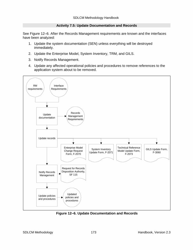
SDLCM Methodology Handbook
SDLCM Methodology 173 Handbook, Version 2.3
RMrequirements
Updatedocumentation
Updatedpolicies andprocedures
InterfaceRequirements
Update policiesand procedures
Request for RecordsDisposition Authority,
SF 115
RecordsManagementRequirements
Update records
Technical ReferenceModel Update Form,
F-2073
GILS Update Form,F-3060
Enterprise ModelChange Request
Form, F-2070
Notify RecordsManagement
System InventoryUpdate Form, F-2071
Figure 12–6. Update Documentation and Records
Activity 7.5: Update Documentation and Records
See Figure 12–6. After the Records Management requirements are known and the interfaceshave been analyzed:
1. Update the system documentation (SEN) unless everything will be destroyedimmediately.
2. Update the Enterprise Model, System Inventory, TRM, and GILS.
3. Notify Records Management.
4. Update any affected operational policies and procedures to remove references to theapplication system about to be removed.

SDLCM Methodology Handbook
SDLCM Methodology 174 Handbook, Version 2.3
Confirmationthat affected
systems havebeen re-deployed
Remove thesystem
Operationalenvironment with
any previousdependencies
removed
PAP
Figure 12–7. Wait for Confirmation and Remove the System
Activity 7.6: Wait for Confirmation and Remove the System
See Figure 12–7.
1. Wait for confirmation that any affected systems have been re-deployed.
2. Using the plans for decommissioning documented in the PMP, remove the system fromthe operational environment. Archive or destroy related processes and data asdocumented in the PMP.
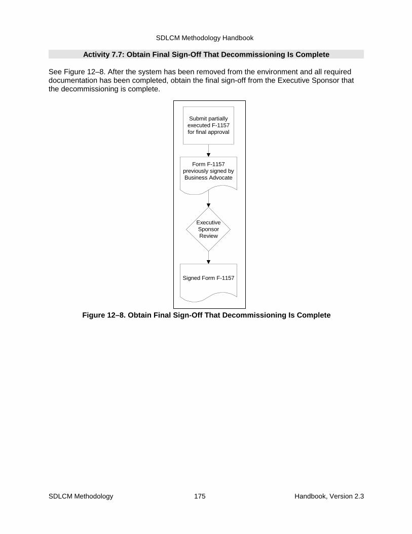
SDLCM Methodology Handbook
SDLCM Methodology 175 Handbook, Version 2.3
ExecutiveSponsorReview
Form F-1157previously signed byBusiness Advocate
Submit partiallyexecuted F-1157for final approval
Signed Form F-1157
Figure 12–8. Obtain Final Sign-Off That Decommissioning Is Complete
Activity 7.7: Obtain Final Sign-Off That Decommissioning Is Complete
See Figure 12–8. After the system has been removed from the environment and all requireddocumentation has been completed, obtain the final sign-off from the Executive Sponsor thatthe decommissioning is complete.
SDLCM Methodology Handbook
SDLCM Methodology 176 Handbook, Version 2.3
Appendix A. Maintaining the SDLCMMethodology
The SDLCM Methodology is the approach to doing business at the NRC. That approach isdescribed by a set of documents, including this handbook and the companion volume ofprocedures, standards, and forms.
As discussed in Section 2.4, every Project provides an opportunity to improve the processdefined by the SDLCM Methodology.
SDLCM Methodology Procedure P–9001 (SDLCM Methodology Change) defines themechanism for reporting deficiencies—or suggesting improvements—in the methodology or inthe documents describing the methodology. To request a change to the SDLCM Methodologyor to any part of its documentation set, follow the steps specified in Procedure P–9001.
SDLCM Methodology Form F–9001 (SDLCM Methodology Change Request Form) is thevehicle for documenting any change.
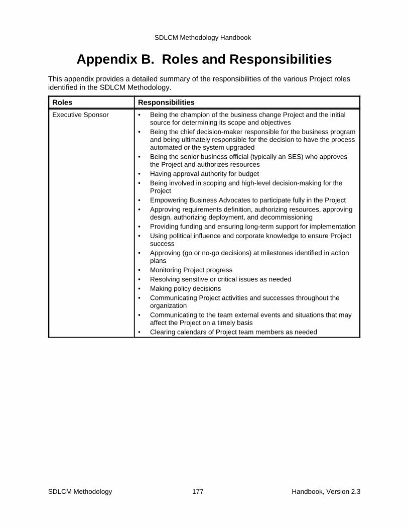
SDLCM Methodology Handbook
SDLCM Methodology 177 Handbook, Version 2.3
Appendix B. Roles and ResponsibilitiesThis appendix provides a detailed summary of the responsibilities of the various Project rolesidentified in the SDLCM Methodology.
Roles Responsibilities
Executive Sponsor • Being the champion of the business change Project and the initialsource for determining its scope and objectives
• Being the chief decision-maker responsible for the business programand being ultimately responsible for the decision to have the processautomated or the system upgraded
• Being the senior business official (typically an SES) who approvesthe Project and authorizes resources
• Having approval authority for budget• Being involved in scoping and high-level decision-making for the
Project• Empowering Business Advocates to participate fully in the Project• Approving requirements definition, authorizing resources, approving
design, authorizing deployment, and decommissioning• Providing funding and ensuring long-term support for implementation• Using political influence and corporate knowledge to ensure Project
success• Approving (go or no-go decisions) at milestones identified in action
plans• Monitoring Project progress• Resolving sensitive or critical issues as needed• Making policy decisions• Communicating Project activities and successes throughout the
organization• Communicating to the team external events and situations that may
affect the Project on a timely basis• Clearing calendars of Project team members as needed
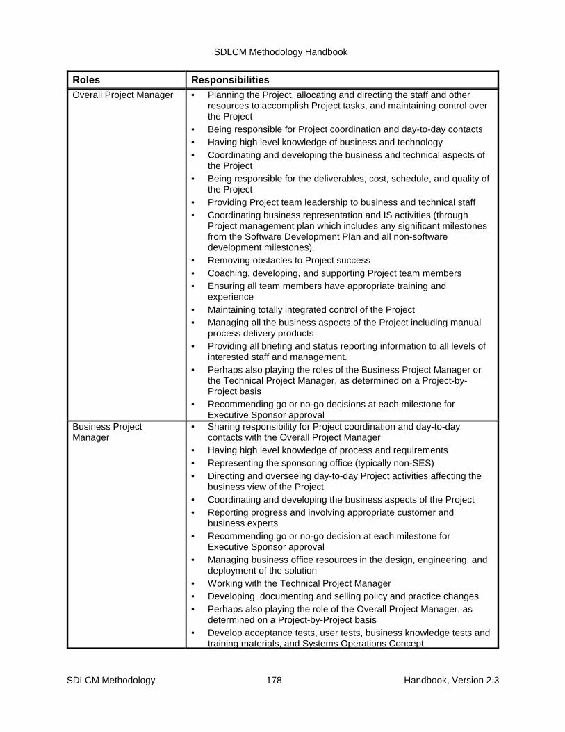
SDLCM Methodology Handbook
Roles Responsibilities
SDLCM Methodology 178 Handbook, Version 2.3
Overall Project Manager • Planning the Project, allocating and directing the staff and otherresources to accomplish Project tasks, and maintaining control overthe Project
• Being responsible for Project coordination and day-to-day contacts• Having high level knowledge of business and technology• Coordinating and developing the business and technical aspects of
the Project• Being responsible for the deliverables, cost, schedule, and quality of
the Project• Providing Project team leadership to business and technical staff• Coordinating business representation and IS activities (through
Project management plan which includes any significant milestonesfrom the Software Development Plan and all non-softwaredevelopment milestones).
• Removing obstacles to Project success• Coaching, developing, and supporting Project team members• Ensuring all team members have appropriate training and
experience• Maintaining totally integrated control of the Project• Managing all the business aspects of the Project including manual
process delivery products• Providing all briefing and status reporting information to all levels of
interested staff and management.• Perhaps also playing the roles of the Business Project Manager or
the Technical Project Manager, as determined on a Project-by-Project basis
• Recommending go or no-go decisions at each milestone forExecutive Sponsor approval
Business ProjectManager
• Sharing responsibility for Project coordination and day-to-daycontacts with the Overall Project Manager
• Having high level knowledge of process and requirements• Representing the sponsoring office (typically non-SES)• Directing and overseeing day-to-day Project activities affecting the
business view of the Project• Coordinating and developing the business aspects of the Project• Reporting progress and involving appropriate customer and
business experts• Recommending go or no-go decision at each milestone for
Executive Sponsor approval• Managing business office resources in the design, engineering, and
deployment of the solution• Working with the Technical Project Manager• Developing, documenting and selling policy and practice changes• Perhaps also playing the role of the Overall Project Manager, as
determined on a Project-by-Project basis• Develop acceptance tests, user tests, business knowledge tests and
training materials, and Systems Operations Concept
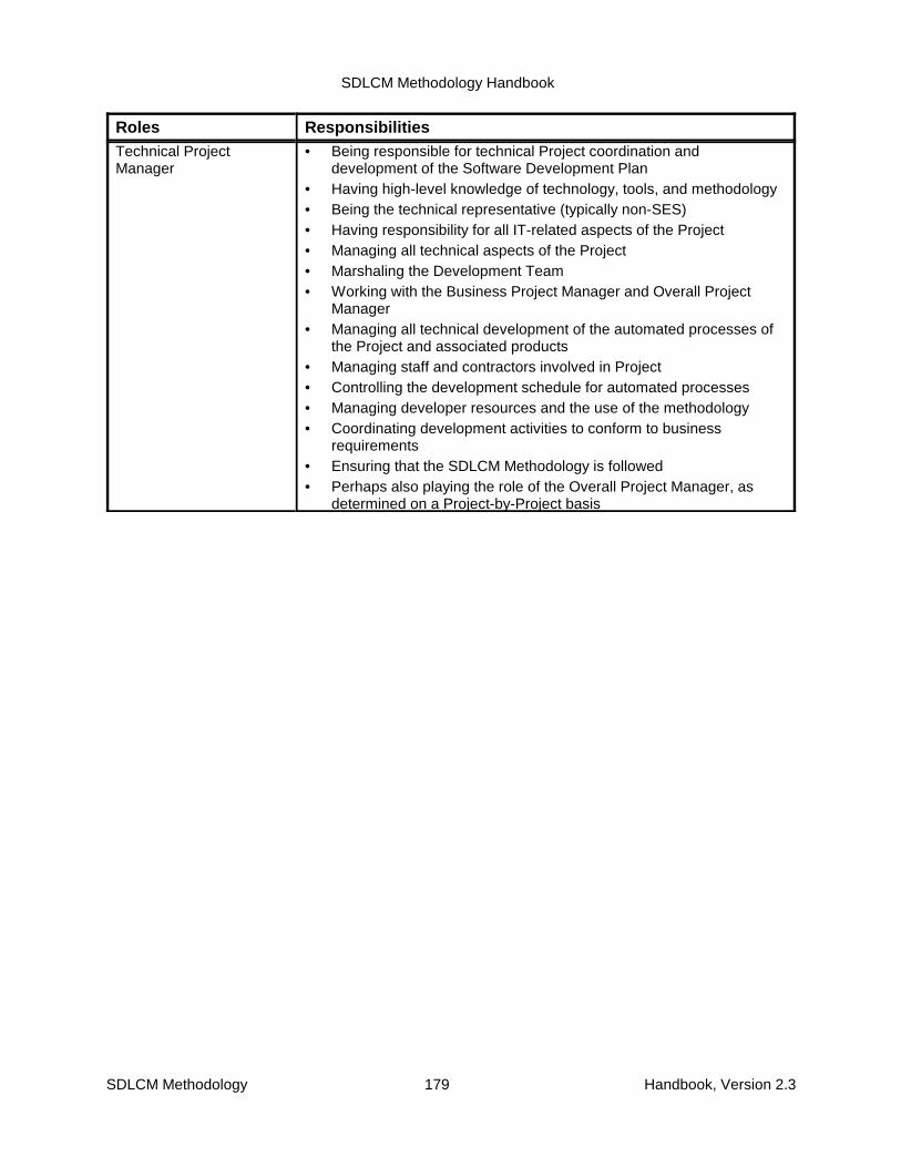
SDLCM Methodology Handbook
Roles Responsibilities
SDLCM Methodology 179 Handbook, Version 2.3
Technical ProjectManager
• Being responsible for technical Project coordination anddevelopment of the Software Development Plan
• Having high-level knowledge of technology, tools, and methodology• Being the technical representative (typically non-SES) • Having responsibility for all IT-related aspects of the Project• Managing all technical aspects of the Project• Marshaling the Development Team• Working with the Business Project Manager and Overall Project
Manager• Managing all technical development of the automated processes of
the Project and associated products• Managing staff and contractors involved in Project• Controlling the development schedule for automated processes• Managing developer resources and the use of the methodology• Coordinating development activities to conform to business
requirements• Ensuring that the SDLCM Methodology is followed• Perhaps also playing the role of the Overall Project Manager, as
determined on a Project-by-Project basis

SDLCM Methodology Handbook
Roles Responsibilities
SDLCM Methodology 180 Handbook, Version 2.3
Business Advocate • Being the primary beneficiary or stakeholder• Being the business leader whose business area is affected most by
the Project and who has the lead role in the direction and use of theapplication outcome
• Driving system requirements• Holding a key role in the business area where the system is being
implemented and perhaps being:� The customer who has a vested interest in the Project (that is, a
real user)
� The functional area manager responsible for the business areawhere the solution is required
� The principal user responsible for success of the Project
• Keeping the vision for the business needs of the Project• Being a visionary who identifies problems and recognizes the need
for improvement in a business area• Seeking authorization and approval from the Executive Sponsor• Being an enthusiast, a sales person, a resource identifier, and a
business verifier• Overcoming Project problems in all areas (resources, scoping,
design, selling, installation)• Selling the solution upward to executive management and executive
sponsorship• Selling the business need downward and outward to all involved with
the Project (equivalent of private industry program or matrixmanagement)
• Ensuring that all business requirements have been addressed by thesolution
• Reviews and recommends approval of all Project plans andproducts/deliverables
• Identifying and resolving critical issues• Obtaining approval for new business policies and practices to
support the new solution• Participating in the implementation of the solution within his or her
own business area• Working closely with development team to ensure compliance with
business area requirements• Testing and reporting discrepancies
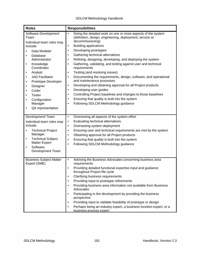
SDLCM Methodology Handbook
Roles Responsibilities
SDLCM Methodology 181 Handbook, Version 2.3
Software DevelopmentTeam
Individual team roles mayinclude:
• Data Modeler• Database
Administrator• Knowledge
Coordinator• Analyst• JAD Facilitator• Prototype Developer• Designer• Coder• Tester• Configuration
Manager• QA representative
• Doing the detailed work on one or more aspects of the system(definition, design, engineering, deployment, service ordecommissioning)
• Building applications• Developing prototypes• Gathering technical alternatives• Refining, designing, developing, and deploying the system• Gathering, validating, and testing against user and technical
requirements• Testing (and resolving issues) • Documenting the requirements, design, software, and operational
and maintenance processes• Developing and obtaining approval for all Project products• Developing user guides• Controlling Project baselines and changes to those baselines• Ensuring that quality is built into the system• Following SDLCM Methodology guidance
Development Team
Individual team roles mayinclude:
• Technical ProjectManager
• Technical SubjectMatter Expert
• SoftwareDevelopment Team
• Overseeing all aspects of the system effort• Evaluating technical alternatives• Overseeing system deployment• Ensuring user and technical requirements are met by the system• Obtaining approval for all Project products• Ensuring that quality is built into the system• Following SDLCM Methodology guidance
Business Subject MatterExpert (SME)
• Advising the Business Advocates concerning business arearequirements
• Providing detailed functional expertise input and guidancethroughout Project life cycle
• Clarifying business requirements• Providing input to prototype refinements• Providing business area information not available from Business
Advocates• Participating in the development by providing the business
perspective• Providing input to validate feasibility of prototype or design• Perhaps being an industry expert, a business function expert, or a
business process expert

SDLCM Methodology Handbook
Roles Responsibilities
SDLCM Methodology 182 Handbook, Version 2.3
Technical Subject MatterExpert (SME)
• Being an authority who has specialized knowledge of the technicalside of the Project
• Providing technical expertise to the Development Team• Being infrastructure experts, component hardware or software
experts, application package experts, or product and technologyexperts
• Working closely with the Development Team to ensure that thetechnical solution conforms to business requirements
• Providing detailed technical expertise• Identifying potential fixes• Providing input that defines or clarifies technical requirements• Advising the Development Team on alternative designs,
development approaches, applicable new technologies, etc.Other Representatives orStakeholders
• Representing the business needs of non-lead office(s) significantlyaffected by the system being developed or affected by the outcomeof the solution
• Providing input and perspective to Project plans and deliverables
SDLCM Methodology Handbook
SDLCM Methodology 183 Handbook, Version 2.3
Appendix C. Products of ProjectsThis appendix identifies and summarizes all products of Projects as specified by NRC’s SDLCMMethodology and specifies which products are required. Use this appendix together withAppendix D, which summarizes the activities and identifies the products of each activity, as across-reference to the component descriptions in the main body of this handbook.
Section 2 summarizes the products of NRC Projects, organized by the component of themethodology within which the product is initially created.
Section 2 addresses legacy systems.
C.1 Products of Projects by SDLCM Methodology Component
The tables in this section summarize the products according to the components in which theyare initially created. For a convenient listing of all products ordered by product identificationnumbers, see the Table of Contents of the companion volume of SDLCM MethodologyProcedures, Standards, and Forms. The standards and forms in that volume represent theproducts of Projects.
The SDLCM Methodology distinguishes among activities associated with (1) new development,(2) enhancement, and (3) maintenance of application systems. See Chapter 2, “MethodologyOverview,” and Chapter 11, “Component 6. Service the Solution,” for more information.
� Tables C–1 through C–5 (products of Components 1 through 5) pertain to newdevelopment and enhancement Projects.
� Table C–6 (products of Component 6) pertains to operational systems that have beendeployed and are under maintenance.
� Table C–7 (products of Component 7) pertains to any operational system that is beingdecommissioned.
When performing maintenance (Component 6), update only the system documentationproducts that are needed to support further system maintenance. For example, if the softwareor system tests are modified, then update the Test Plan; if the user interface or functionality ismodified, then update the User Guide. Do not update any system documentation products thatare not affected by the maintenance change. See also Section C.2.

SDLCM Methodology Handbook
SDLCM Methodology 184 Handbook, Version 2.3
Table C–1. Products Created within Component 1ProductName
Created inComponent
Updated inComponents
Product Summary
RequiredProduct?
Project Charter(S–1051)
1 The Project charter is a managementdocument used to initiate an NRC Project thatwill be developed using the SDLCMMethodology. The Project charter identifiesthe high-level goals and objectives of theProject. It specifies the Project’s keypersonnel, including the Executive Sponsorand Overall Project Manager, and commitstheir time and resources. It provides thebackground, scope, and a high-level approachfor its development. It also identifies anyconstraints and critical success factorsnecessary to the management of the Project.
Required fornewdevelop-mentProjects.
Not requiredfor en-hancementProjects.
SystemRequirementsSpecification(S–3051)
1 3,4,6 The SRS clarifies the scope of the Project. Itcontains the system functional requirements,data requirements, an assessment of thecurrent system (if any), an analysis ofalternative approaches for satisfying therequirements, and a system operationsconcept.
Required
Current SystemAssessmentDocument(S–3052)
1 Use the Current System AssessmentDocument to document the results of theassessment of the current system if theassessment is complex and cannot besummarized in the System RequirementsSpecification.
Required
ProjectManagement Plan(S–1052)
1 2,3,4,5,6,7 The PMP communicates to management, thecustomer, and Project members the overallplan for performing and managing the Projectfrom start to end.
Required
SoftwareDevelopmentPlan (S-1057)
1 2,3,4,5,6,7 The software development plan, provides thedetailed activities and schedules fordesigning, coding, integrating, and testingnew, legacy, and COTS software modules toprovide the full functionality of the software forthe Project. It is developed on Projects thatinclude software development or integrationafter Project software requirements have beenidentified.
Required
SystemOperationsConcept (S-3053)
1 2,3 Initially developed by the Overall ProjectManager, Business Advocates, and BusinessSubject Matter Experts as a high level conceptof the envisioned system for use in validatingcompleteness of requirements list and bydesigners in developing process models anddata models.
Required
AlternativesAnalysisDocument (S-3054)
1 2,3 Used by those persons who are responsiblefor the evaluation of alternative approaches toaddressing the options and associated costsand risks for delivering new or enhancedapplication systems or correcting problemswith existing application systems.
Required

SDLCM Methodology Handbook
ProductName
Created inComponent
Updated inComponents
Product Summary
RequiredProduct?
SDLCM Methodology 185 Handbook, Version 2.3
Quality AssurancePlan (S-2001)
1 2,3 The Quality Assurance Plan (QAP) is amanagement document, based on the ProjectManagement Plan (PMP), that defines thequality role and responsibilities duringdevelopment and/or maintenance for aspecific Project. This information includesidentification of quality resources, activitiesand processes that are to be implemented forthe identified Project.
Required
ConfigurationManagement Plan(S-3501)
1 2,3 The Configuration Management Plan (CMP) isa management document that identifies theorganization that performs ConfigurationManagement (CM) for the Project/Task. It istypically produced in a high level form duringthe early components of the SDLCMMprocess and is defined at a lower level ofdetail by the end of Component 3.
Required
TacticalIntegration Plan(S–5051)
1 2,3,4,5,6 The TIP serves as notification of the intendeddeployment of a system or application andprovides the time frame for scheduledoperation. It provides NRC management withthe information necessary to (1) ensure thatthe level of planning is sufficient to proceedwith the system deployment described, (2)assess the impact on other components of theNRC Enterprise Model, and (3) confirm theadequacy of the schedule and budget tocomplete the deployment and initial operation.
Required
Support ResourceAcquisitionRequest andCommitmentForm (F–1061)
1,6 Use this form, if needed, to identify andrequest personnel and other resources.
Requiredonly ifneeded
EnvironmentChange RequestForm (F–1601)
1,6 Use this form, if needed, to identify andrequest new or upgraded technology(including tools) that will change the NRCcomputing environment.
Requiredonly ifneeded
Notification ofElectronicInformationSystem Design orModification (NRCForm 616)
1,6 Use this form to notify the RecordsManagement Branch that a system is beingdesigned or modified. RM will assign arepresentative to act as its interface with theProject Manager.
Required
RecordsRetention andDispositionAuthority (NRCForm 331)
1,7 Use this form to notify the RecordsManagement Branch of the potential need toestablish or change the disposition of officialrecords.
Required
InformationSystemDescription (NAForm 14028)
1 Use this form to provide a description of thesystem to the Records Management Branch.
Required
Request forRecordsDispositionAuthority (SF 115)
1,7 Use this form to propose a disposition ofrecords. RM will submit the request to NARA.
Required
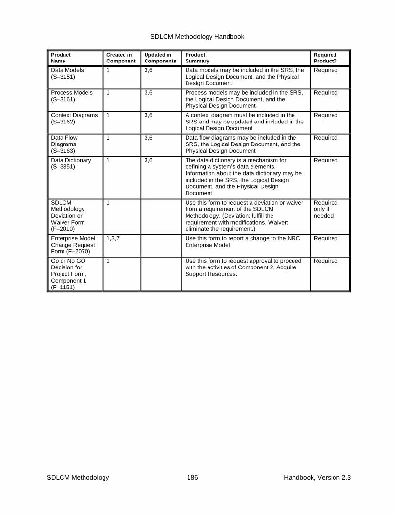
SDLCM Methodology Handbook
ProductName
Created inComponent
Updated inComponents
Product Summary
RequiredProduct?
SDLCM Methodology 186 Handbook, Version 2.3
Data Models(S–3151)
1 3,6 Data models may be included in the SRS, theLogical Design Document, and the PhysicalDesign Document
Required
Process Models(S–3161)
1 3,6 Process models may be included in the SRS,the Logical Design Document, and thePhysical Design Document
Required
Context Diagrams(S–3162)
1 3,6 A context diagram must be included in theSRS and may be updated and included in theLogical Design Document
Required
Data FlowDiagrams(S–3163)
1 3,6 Data flow diagrams may be included in theSRS, the Logical Design Document, and thePhysical Design Document
Required
Data Dictionary(S–3351)
1 3,6 The data dictionary is a mechanism fordefining a system’s data elements.Information about the data dictionary may beincluded in the SRS, the Logical DesignDocument, and the Physical DesignDocument
Required
SDLCMMethodologyDeviation orWaiver Form(F–2010)
1 Use this form to request a deviation or waiverfrom a requirement of the SDLCMMethodology. (Deviation: fulfill therequirement with modifications. Waiver:eliminate the requirement.)
Requiredonly ifneeded
Enterprise ModelChange RequestForm (F–2070)
1,3,7 Use this form to report a change to the NRCEnterprise Model
Required
Go or No GODecision forProject Form,Component 1(F–1151)
1 Use this form to request approval to proceedwith the activities of Component 2, AcquireSupport Resources.
Required

SDLCM Methodology Handbook
SDLCM Methodology 187 Handbook, Version 2.3
Table C–2. Products Created or Updated within Component 2Product Name Created in
ComponentUpdated inComponents
Product Summary RequiredProduct?
ProjectManagementPlan (S–1052)
1 2,3,4,5,6,7 (See Component 1.) Required
TacticalIntegration Plan(S–5051)
1 2,3,4,5,6 (See Component 1.) Required
Developmentand MaintenanceEnvironmentProductsInstallation Plan(S–1055)
2 6 The Development and MaintenanceEnvironment Products InstallationPlan provides a detailed descriptionof the activities involved in theinstallation of all resources requiredto design, engineer, and maintain thesystem. It defines responsibilities,schedules, risks, and risk mitigationapproaches.
Required only ifneeded
Statement ofWork (S–1053)
2 The SOW is the Project manager’sdescription of the resources requiredfrom the contractor who will providethem. It serves as the basis of acontractual agreement with thesupplier for the acquisition ofresources required for the Project.
Required only ifneeded
SupportResourceAcquisitionStrategy Form(F–1062)
2 Use this form to document thestrategy for acquiring the neededresources.
Required only ifneeded
DeveloperTrainingRequirementsForm (F–7051)
2 Use this form to document thetraining requirements for Projectpersonnel.
Required only ifneeded
Fully Staffed andTrained TeamForm (F–1181)
2 Use this form to document the rolesof the Project personnel and todocument that required training hasbeen completed.
Required
Go or No GODecision forProject Form,Component 2(F–1152)
2 Use this form to request approval toproceed with the activities ofComponent 3, Design the Solution.
Required

SDLCM Methodology Handbook
SDLCM Methodology 188 Handbook, Version 2.3
Table C–3. Products Created or Updated within Component 3Product Name Created in
ComponentUpdated inComponents
Product Summary RequiredProduct?
ProjectManagement Plan(S–1052)
1 2,3,4,5,6,7 (See Component 1.) Required
SoftwareDevelopment Plan (S-1057)
1 2,3,4,5,6,7 (See Component 1.) Required
SystemRequirementsSpecification(S–3051)
1 3,4,6 (See Component 1.) Required
Logical DesignDocument(S–3171)
3 4,6 The Logical Design Document presents thesystem architecture at a level of detail sufficientto begin detailed physical design activities. Ittranslates the system’s requirements,contained in the SRS, into the functions to beperformed by the hardware, software, andfirmware components of the system. It showshow the various components will work togetherto meet the operational requirements.
Required
Physical DesignDocument(S–3172)
3 4,6 The Physical Design Document summarizesthe results of translating the logical designobjects into physical design objects. Thephysical design objects include a relationalschema, a relational table structure diagram,the beginnings of the data definition language,a Data Dictionary, and the screen prototypes.
Required
TacticalIntegration Plan(S–5051)
1 2,3,4,5,6 (See Component 1.) Required
ProductsInstallation andIntegration Plan(S–5052)
3 4,5,6 The Products Installation and Integration Planprovides a detailed description of the activitiesinvolved in the installation and integration ofequipment resources (Commercial orGovernment off-the-shelf (COTS or GOTS)hardware and software and custom-developedsoftware) required for the deployment of thesolution system. It defines responsibilities,schedules, risks, and risk mitigationapproaches.
Required ifnot includedin update ofTIP
SolutionIntegration Plan(S–5053)
3 4,5,6 The Solution Integration Plan provides adetailed description of the activities involved inthe integrating the hardware and softwareconfiguration items (CIs) of the solution system.It also specifies roles and responsibilities andthe integration schedule, and identifies anyrisks, and risk mitigation approaches applicableto the integration process.
Required ifnot includedin update ofTIP
Other SystemsIntegration Plan(S–5054)
3 4,5,6 The Other Systems Integration Plan provides adetailed description of the activities involved inintegrating the solution system with other NRCsystems, both legacy and new. It definesresponsibilities, schedules, risks, and riskmitigation approaches.
Required ifnot includedin update ofTIP

SDLCM Methodology Handbook
Product Name Created inComponent
Updated inComponents
Product Summary RequiredProduct?
SDLCM Methodology 189 Handbook, Version 2.3
External SystemsInterfaceDiagrams(S–3164)
3 An external systems interface diagram is ahigh-level data flow diagram that shows anapplication with its interfaces to existing or newcomputer systems or agents. It illustratesprocess, external agents, external interfaces,and shared external databases. The diagrammay be included in the LDD and PDD, ifneeded.
Required inLDD andPDD if thereareinterfaces toexternalsystems
Other IntegrationIssues Plan(S–5055)
3 4,5,6 The Other Integration Issues Plan provides adetailed description of the activities involved inaccomplishing any integration issues notcovered by other plans. It definesresponsibilities, schedules, risks, and riskmitigation approaches.
May beincluded inthe TacticalIntegrationPlan (TIP)forintegrationissues notcovered byany otherintegrationplan.
Conversion Plan(S–1054)
3 4,5,6 The Conversion Plan provides a detaileddescription of what data will be converted,where the data will come from, and how thesupporting business process will be organized,staffed, and scheduled.
Required ifnot includedin update ofTIP
Security Controls(S–1056)
3 4,5,6 Specifies the set of security controls to beincluded in the developed system.
Required ifnot includedin update ofTIP
IntegratedEducation,Training, andReferenceMaterials(S–7052)
3 6 Summarizes the results of the training designactivities into an organized and logically flowingdeliverable.
Required
Data Models(S–3151)
1 3,6 (See Component 1.) Required
Process Models(S–3161)
1 3,6 (See Component 1.) Required
Context Diagrams(S–3162)
1 3,6 (See Component 1.) Required
Data FlowDiagrams(S–3163)
1 3,6 (See Component 1.) Required
Data Dictionary(S–3351)
1 3,6 (See Component 1.) Required
SoftwareEngineeringNotebook (S-3091)
3 4,5,6 The SEN is an implementation workbook thatconsolidates the information pertinent to asoftware element (or set of software elements).It also ensures ready access to complete andup-to-date information for modification andauditing purposes.
Required
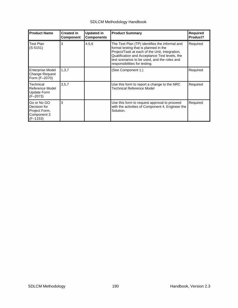
SDLCM Methodology Handbook
Product Name Created inComponent
Updated inComponents
Product Summary RequiredProduct?
SDLCM Methodology 190 Handbook, Version 2.3
Test Plan (S-5151)
3 4,5,6 The Test Plan (TP) identifies the informal andformal testing that is planned in theProject/Task at each of the Unit, Integration,Qualification and Acceptance Test levels, thetest scenarios to be used, and the roles andresponsibilities for testing.
Required
Enterprise ModelChange RequestForm (F–2070)
1,3,7 (See Component 1.) Required
TechnicalReference ModelUpdate Form(F–2073)
3,5,7 Use this form to report a change to the NRCTechnical Reference Model
Required
Go or No GODecision forProject Form,Component 3(F–1153)
3 Use this form to request approval to proceedwith the activities of Component 4, Engineer theSolution.
Required

SDLCM Methodology Handbook
SDLCM Methodology 191 Handbook, Version 2.3
Table C–4. Products Created or Updated within Component 4Product Name Created in
ComponentUpdated inComponents
Product Summary RequiredProduct?
ProjectManagementPlan (S–1052)
1 2,3,4,5,6,7 (See Component 1.) Required
SoftwareDevelopmentPlan (S-1057)
1 2,3,4,5,6,7 (See Component 1.) Required
SystemRequirementsSpecification(S–3051)
1 3,4,6 (See Component 1.) Required
SystemOperationsConcept
(S-3053)
1 4 (See Component 1.) Required
AlternativesAnalysisDocument
(S-3054)
1 4 (See Component 1.) Required
TacticalIntegrationPlan (S–5051)
1 2,3,4,5,6 (See Component 1.) Required
ExternalSystemsInterfaceDiagram
(S-3164)
3 4 (See Component 3.) Required
Logical DesignDocument(S–3171)
3 4,6 (See Component 3.) Required
PhysicalDesignDocument(S–3172)
3 4,6 (See Component 3.) Required
Test Plan(S–5151)
3 4,5,6 (See Component 3.) Required
OtherIntegrationIssues Plan(S–5055)
3 4,5,6 (See Component 3.) Required ifnotincluded inupdate ofTIP
ConversionPlan (S–1054)
3 4,5,6 (See Component 3.) Required ifnotincluded inupdate ofTIP

SDLCM Methodology Handbook
Product Name Created inComponent
Updated inComponents
Product Summary RequiredProduct?
SDLCM Methodology 192 Handbook, Version 2.3
SecurityControls(S–1056)
3 4,5,6 (See Component 3.) Required ifnotincluded inupdate ofTIP
SolutionIntegrationPlan
(S-5053)
3 4 (See Component 3.) Required ifnotincluded inupdate ofTIP
Other SystemsIntegrationPlan
(S-5054)
3 4 (See Component 3.) Required ifnotincluded inupdate ofTIP
InstallationInstructions(S–5252)
4 5, 6 The Installation Instructions document providesa detailed description of the activities involvedin the installation of a new or enhanced NRCsystem and the equipment resources, bothhardware and software, required for its supportin the production environment.
Required ifnotincluded inupdate ofTIP
OperationalSupport Guide(S–6151)
4 6 The Operational Support Guide providesguidance to operators and system supportpersonnel on how to support users byperforming specific tasks in a timely manner. Itincludes not only servicing users on an event-driven basis, but also performing some tasksperiodically.
Required
User Trainingand OrientationPlan (S–7053)
4 6 The User Training and Orientation Planprovides a detailed plan for assessing the skillsof users, providing training and orientation toenable users to operate the new system,specifying the budget and training schedule,and assessing the effectiveness of the trainingprogram.
Required
User Guide(S–6051)
4 6 The User Guide provides guidance on how touse the system effectively and efficiently.
Required
On-Line HelpSystem andTutorials(S–6052)
4 6 The On-Line Help System and Tutorialsdocument is a brief overview of the on-line helpand tutorials that are available.
Required
SoftwareEngineeringNotebook(S–3091)
3 4,5,6,7 (See Component 3.) Required
NetworkIntegrationDiagrams(S–5056)
4 A set of network diagrams depicts the networksupport required by the logical design of thesystem. The form of the diagrams will bedetermined by the size and complexity of thesystem being developed or enhanced. Thediagrams are included in the TIP.
Requiredin the TIP ifthe systemruns on anetwork

SDLCM Methodology Handbook
Product Name Created inComponent
Updated inComponents
Product Summary RequiredProduct?
SDLCM Methodology 193 Handbook, Version 2.3
Target UsersCapabilityUpgradeRequest Form(F–6054)
4,6 Use this form to request capability upgrades fortargeted users.
Requiredonly ifneeded
Change LogForm (F–2561)
4,5,6 The configuration management office uses thisform to maintain a record of all changeproposals.
Requiredonly ifChangeProposalshave beensubmitted
ChangeProposal Form(F–2502)
4,5,6 Use this form to request a change to abaselined system.
Requiredonly ifchangesareneeded
Go or No GODecision for Project Form,Component 4(F–1154)
4 Use this form to request approval to proceedwith the activities of Component 5, Deploy theSolution.
Required

SDLCM Methodology Handbook
SDLCM Methodology 194 Handbook, Version 2.3
Table C–5. Products Created or Updated within Component 5Product
Name
Created in
Component
Updated in
Components
Product
Summary
Required
Product?
ProjectManagement Plan(S–1052)
1 2,3,4,5,6,7 (See Component 1.) Required
Tactical IntegrationPlan (S–5051)
1 2,3,4,5,6 (See Component 1.) Required
Test Plan (S-5151) 3 4,5,6 (See Component 3.) Required
Other IntegrationIssues Plan(S–5055)
3 4,5,6 (See Component 3.) Required if notincluded inupdate of TIP
Change ProposalForm (F–2502)
4,5,6 (See Component 4.) Required only ifchanges areneeded
Problem ReportForm (F–2251)
5,6,7 Use this form to report a problemwith a deployed system.
Required only if aproblem isidentified
Problem Report LogForm (F–2252)
5,6,7 The configuration managementoffice uses this form to maintain arecord of all Problem Reports.
Required only ifProblem Reportshave beensubmitted
SoftwareEngineeringNotebook (S–3091)
3 4,5,6,7 (See Component 3.) Required
System InventoryUpdate Form(F–2071)
5,7 Use this form to submit an updateto the System Inventory
Required
TechnicalReference ModelUpdate Form(F–2073)
3,5,7 (See Component 3.) Required
GovernmentInformation LocatorSystem (GILS)Update Form(F–3060)
5,7 Use this form to submit an updateto the GILS.
Required
InstallationInstructions(S–5252)
4 5,6 (See Component 4.) Required if notincluded inupdate of TIP
Installation ReportForm (F-5254)
5,6 Use this form to report the resultsof installing the system.
Required only ifneeded
Rollout Report Form(F–5255)
5,6 Use this form to report on thereadiness for the system to bemoved to operational status.
Required only ifneeded
Performance ReportForm (F–5256)
5 Use this form to report that thesystem is ready for acceptancetesting.
Required only ifneeded
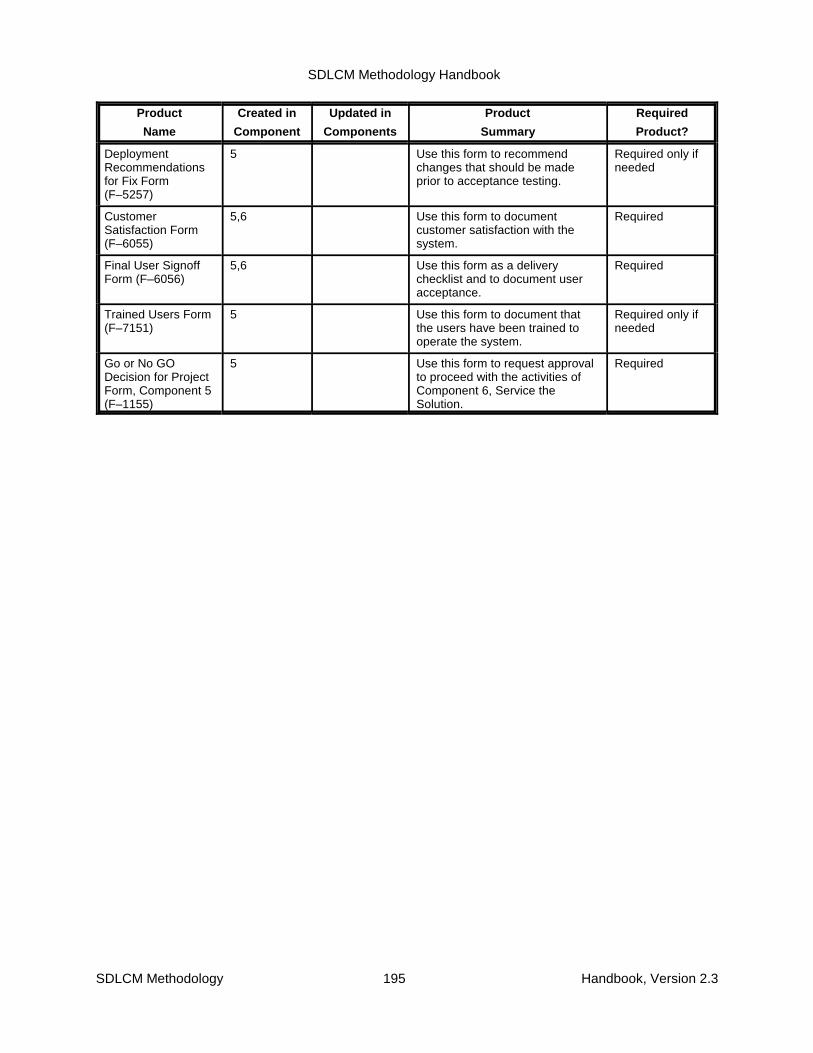
SDLCM Methodology Handbook
Product
Name
Created in
Component
Updated in
Components
Product
Summary
Required
Product?
SDLCM Methodology 195 Handbook, Version 2.3
DeploymentRecommendationsfor Fix Form(F–5257)
5 Use this form to recommendchanges that should be madeprior to acceptance testing.
Required only ifneeded
CustomerSatisfaction Form(F–6055)
5,6 Use this form to documentcustomer satisfaction with thesystem.
Required
Final User SignoffForm (F–6056)
5,6 Use this form as a deliverychecklist and to document useracceptance.
Required
Trained Users Form(F–7151)
5 Use this form to document thatthe users have been trained tooperate the system.
Required only ifneeded
Go or No GODecision for ProjectForm, Component 5(F–1155)
5 Use this form to request approvalto proceed with the activities ofComponent 6, Service theSolution.
Required
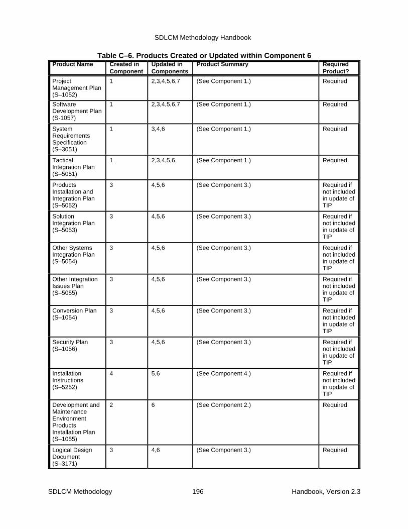
SDLCM Methodology Handbook
SDLCM Methodology 196 Handbook, Version 2.3
Table C–6. Products Created or Updated within Component 6Product Name Created in
ComponentUpdated inComponents
Product Summary RequiredProduct?
ProjectManagement Plan(S–1052)
1 2,3,4,5,6,7 (See Component 1.) Required
SoftwareDevelopment Plan (S-1057)
1 2,3,4,5,6,7 (See Component 1.) Required
SystemRequirementsSpecification(S–3051)
1 3,4,6 (See Component 1.) Required
TacticalIntegration Plan(S–5051)
1 2,3,4,5,6 (See Component 1.) Required
ProductsInstallation andIntegration Plan(S–5052)
3 4,5,6 (See Component 3.) Required ifnot includedin update ofTIP
SolutionIntegration Plan(S–5053)
3 4,5,6 (See Component 3.) Required ifnot includedin update ofTIP
Other SystemsIntegration Plan(S–5054)
3 4,5,6 (See Component 3.) Required ifnot includedin update ofTIP
Other IntegrationIssues Plan(S–5055)
3 4,5,6 (See Component 3.) Required ifnot includedin update ofTIP
Conversion Plan(S–1054)
3 4,5,6 (See Component 3.) Required ifnot includedin update ofTIP
Security Plan(S–1056)
3 4,5,6 (See Component 3.) Required ifnot includedin update ofTIP
InstallationInstructions(S–5252)
4 5,6 (See Component 4.) Required ifnot includedin update ofTIP
Development andMaintenanceEnvironmentProductsInstallation Plan(S–1055)
2 6 (See Component 2.) Required
Logical DesignDocument(S–3171)
3 4,6 (See Component 3.) Required
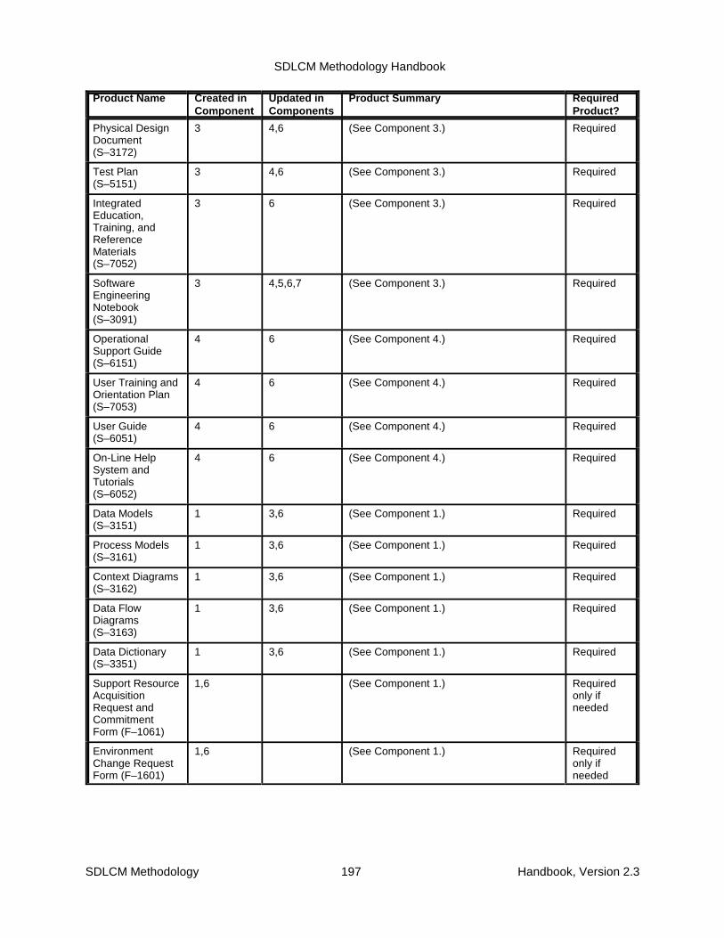
SDLCM Methodology Handbook
Product Name Created inComponent
Updated inComponents
Product Summary RequiredProduct?
SDLCM Methodology 197 Handbook, Version 2.3
Physical DesignDocument(S–3172)
3 4,6 (See Component 3.) Required
Test Plan(S–5151)
3 4,6 (See Component 3.) Required
IntegratedEducation,Training, andReferenceMaterials(S–7052)
3 6 (See Component 3.) Required
SoftwareEngineeringNotebook(S–3091)
3 4,5,6,7 (See Component 3.) Required
OperationalSupport Guide(S–6151)
4 6 (See Component 4.) Required
User Training andOrientation Plan(S–7053)
4 6 (See Component 4.) Required
User Guide(S–6051)
4 6 (See Component 4.) Required
On-Line HelpSystem andTutorials(S–6052)
4 6 (See Component 4.) Required
Data Models(S–3151)
1 3,6 (See Component 1.) Required
Process Models(S–3161)
1 3,6 (See Component 1.) Required
Context Diagrams(S–3162)
1 3,6 (See Component 1.) Required
Data FlowDiagrams(S–3163)
1 3,6 (See Component 1.) Required
Data Dictionary(S–3351)
1 3,6 (See Component 1.) Required
Support ResourceAcquisitionRequest andCommitmentForm (F–1061)
1,6 (See Component 1.) Requiredonly ifneeded
EnvironmentChange RequestForm (F–1601)
1,6 (See Component 1.) Requiredonly ifneeded

SDLCM Methodology Handbook
Product Name Created inComponent
Updated inComponents
Product Summary RequiredProduct?
SDLCM Methodology 198 Handbook, Version 2.3
Notification ofElectronicInformationSystem Design orModification (NRCForm 616)
1,6 (See Component 1.) Required
Solution ModulesReady forDeployment Form(F–4051)
4,6 (See Component 4.) Requiredonly ifneeded
Solution RolloutSupport Ready forDeployment Form(F–4052)
4,6 (See Component 4.) Requiredonly ifneeded
Change Log Form(F–2561)
4,6 (See Component 4.) Requiredonly ifChangeProposalshave beensubmitted
Change ProposalForm (F–2502)
4,5,6 (See Component 4.) Requiredonly ifchanges areneeded
Installation ReportForm (F-5254)
5,6 (See Component 5.) Requiredonly ifneeded
Problem ReportForm (F–2251)
5,6,7 (See Component 5.) Requiredonly if aproblem isidentified
Problem ReportLog Form(F–2252)
5,6,7 (See Component 5.) Requiredonly ifProblemReportshave beensubmitted
Rollout ReportForm (F–5255)
5,6 (See Component 5.) Requiredonly if
needed
Target UsersCapabilityUpgrade RequestForm (F–6054)
4,6 (See Component 4.) Requiredonly ifneeded
CustomerSatisfaction Form(F–6055)
5,6 (See Component 5.) Required
Final User SignoffForm (F–6056)
5,6 (See Component 5.) Required

SDLCM Methodology Handbook
Product Name Created inComponent
Updated inComponents
Product Summary RequiredProduct?
SDLCM Methodology 199 Handbook, Version 2.3
Go or No GODecision forProject Form,Component 6(F–1156)
6 Use this form to request approval toterminate maintenance support for anapplication system.
Required
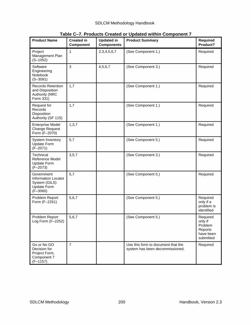
SDLCM Methodology Handbook
SDLCM Methodology 200 Handbook, Version 2.3
Table C–7. Products Created or Updated within Component 7Product Name Created in
ComponentUpdated inComponents
Product Summary RequiredProduct?
ProjectManagement Plan(S–1052)
1 2,3,4,5,6,7 (See Component 1.) Required
SoftwareEngineeringNotebook(S–3091)
3 4,5,6,7 (See Component 3.) Required
Records Retentionand DispositionAuthority (NRCForm 331)
1,7 (See Component 1.) Required
Request forRecordsDispositionAuthority (SF 115)
1,7 (See Component 1.) Required
Enterprise ModelChange RequestForm (F–2070)
1,3,7 (See Component 1.) Required
System InventoryUpdate Form(F–2071)
5,7 (See Component 5.) Required
TechnicalReference ModelUpdate Form(F–2073)
3,5,7 (See Component 3.) Required
GovernmentInformation LocatorSystem (GILS)Update Form(F–3060)
5,7 (See Component 5.) Required
Problem ReportForm (F–2251)
5,6,7 (See Component 5.) Requiredonly if aproblem isidentified
Problem ReportLog Form (F–2252)
5,6,7 (See Component 5.) Requiredonly ifProblemReportshave beensubmitted
Go or No GODecision forProject Form,Component 7(F–1157)
7 Use this form to document that thesystem has been decommissioned.
Required
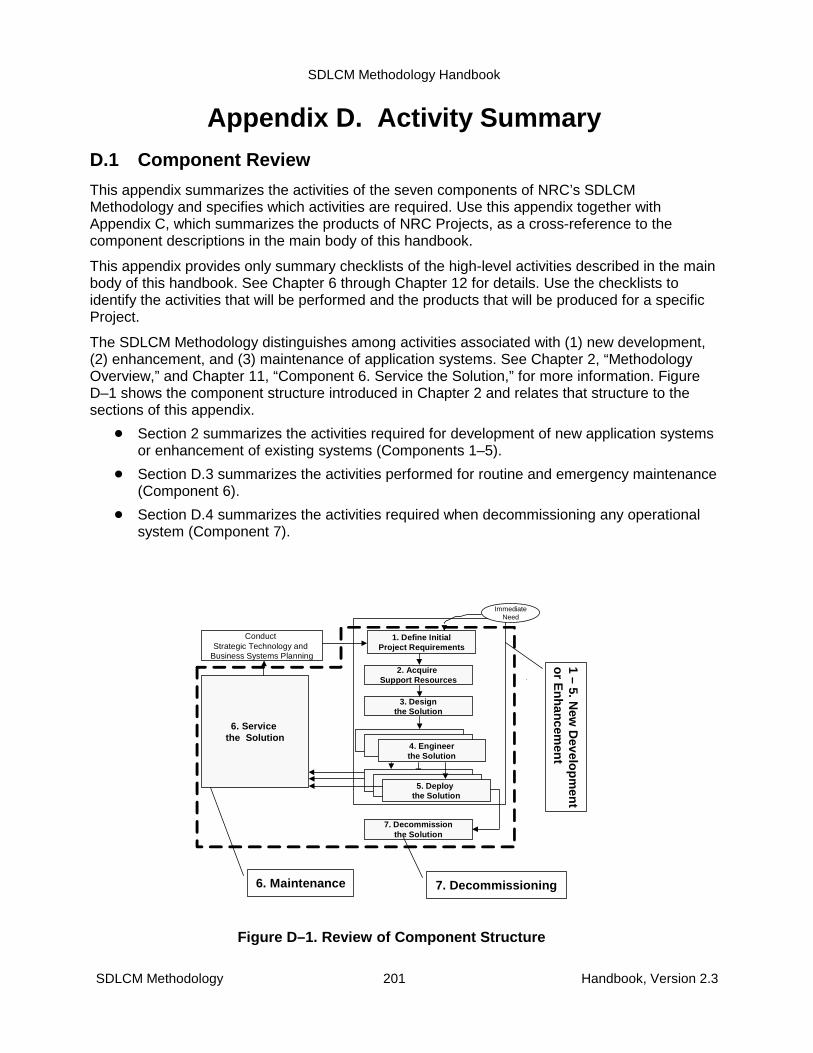
SDLCM Methodology Handbook
SDLCM Methodology 201 Handbook, Version 2.3
6. Maintenance
Conduct Strategic Technology and
Business Systems Planning
ImmediateNeed
7. Decommissionthe Solution
6. Service the Solution
3. Designthe Solution
2. Acquire Support Resources
1. Define InitialProject Requirements
4. Engineerthe Solution
5. Deploy the Solution
1 –5. N
ew D
evelop
men
t o
r En
han
cemen
t
7. Decommissioning
Figure D–1. Review of Component Structure
Appendix D. Activity SummaryD.1 Component Review
This appendix summarizes the activities of the seven components of NRC’s SDLCMMethodology and specifies which activities are required. Use this appendix together withAppendix C, which summarizes the products of NRC Projects, as a cross-reference to thecomponent descriptions in the main body of this handbook.
This appendix provides only summary checklists of the high-level activities described in the mainbody of this handbook. See Chapter 6 through Chapter 12 for details. Use the checklists toidentify the activities that will be performed and the products that will be produced for a specificProject.
The SDLCM Methodology distinguishes among activities associated with (1) new development,(2) enhancement, and (3) maintenance of application systems. See Chapter 2, “MethodologyOverview,” and Chapter 11, “Component 6. Service the Solution,” for more information. FigureD–1 shows the component structure introduced in Chapter 2 and relates that structure to thesections of this appendix.
� Section 2 summarizes the activities required for development of new application systemsor enhancement of existing systems (Components 1–5).
� Section D.3 summarizes the activities performed for routine and emergency maintenance(Component 6).
� Section D.4 summarizes the activities required when decommissioning any operationalsystem (Component 7).
SDLCM Methodology Handbook
SDLCM Methodology 202 Handbook, Version 2.3
D.2 New Development and Enhancement
This section summarizes the activities performed for new development and enhancement ofapplication systems. Chapters 6 through 10 provide the details. See Appendix C for a summaryof the products that must be produced.
The five tables in this section can be used as checklists for tailoring the SDLCM Methodology tothe specific needs of new development and enhancement Projects.
Remember: activities are not sequential steps. Although some activities cannot be started until apredecessor activity is complete, others can be performed concurrently. The diagrams in themain body of this handbook clarify the dependencies among activities.

SDLCM Methodology Handbook
SDLCM Methodology 203 Handbook, Version 2.3
Table D–1. Checklist for Component 11. Define Initial Project Requirements (2 Pages)
Activities Products Activity Req’d
Act.ID Activity Products
Standards orForms
NewDevelop-
mentEnhance-
ments
� 1.1 Clearly identify information managementproblem
Project Charter S–1051 X
� 1.2 Clarify the Project scope System RequirementsSpecification
• Section 1.3 Scope
System OperationsConcept
S–3051
S-3053
X
X
X
� 1.3 Establish a Project Plan and Project SupportControls
Project Management Plan
Quality Assurance Plan
ConfigurationManagement Plan
SDLCMM Deviation orWaiver Form
S–1052
S-2001
S-3501
F-2010
X
X
X
X
X
X
� 1.4 Establish the Software Development Plan Software DevelopmentPlan
S-1057 X X
� 1.5 Notify Records Management Branch to ReviewRecords Management Requirements.
Government Forms NRC Form616
NRC Form331
NA Form14028
SF 115
X
X
X
X
� 1.6 Identify requirements System RequirementsSpecification
Supporting Standards
Data Models
Process Models
Context Diagrams
Data Flow Diagrams
Data Dictionary
System OperationsConcept
Enterprise Model ChangeRequest Form
S–3051
S–3151
S–3161
S–3162
S–3163
S–3351
S–3053
F-2070
X
X
X
X
X
X
X
X
X
� 1.7 Analyze alternatives Alternatives AssessmentDocument
Current SystemAssessment Document
S-3054
S-3052
X
X
X
� 1.8 Review the toolkit Software DevelopmentPlan
S-1057 X X

SDLCM Methodology Handbook
1. Define Initial Project Requirements (2 Pages)
Activities Products Activity Req’d
Act.ID Activity Products
Standards orForms
NewDevelop-
mentEnhance-
ments
SDLCM Methodology 204 Handbook, Version 2.3
� 1.9 Develop a support resource request. Project Management PlanSection 4 - ProjectOrganization
Section 5 - WorkBreakdown Structure
Software DevelopmentPlan
Support ResourcesAcquisition Request Form
Environment ChangeRequest Form
S–1052
S-1057
F-1061
F-1601
X
X
X
X
� 1.10 Plan for deployment. Tactical Integration Plan
Sections for whichinformation can bespecified.
S–5051 X X
� 1.11 Review the Project to make a Go or No-Godecision
Go or No-Go DecisionForm
F–1151 X X
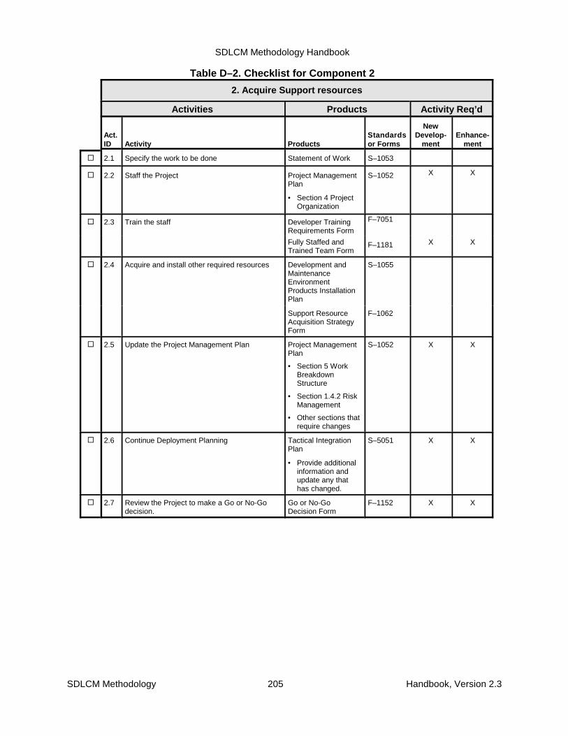
SDLCM Methodology Handbook
SDLCM Methodology 205 Handbook, Version 2.3
Table D–2. Checklist for Component 2
2. Acquire Support resources
Activities Products Activity Req’d
Act.ID Activity Products
Standardsor Forms
NewDevelop-
mentEnhance-
ment
� 2.1 Specify the work to be done Statement of Work S–1053
� 2.2 Staff the Project Project ManagementPlan
• Section 4 ProjectOrganization
S–1052 X X
� 2.3 Train the staff Developer TrainingRequirements Form
F–7051
Fully Staffed andTrained Team Form
F–1181 X X
� 2.4 Acquire and install other required resources Development andMaintenanceEnvironmentProducts InstallationPlan
S–1055
Support ResourceAcquisition StrategyForm
F–1062
� 2.5 Update the Project Management Plan Project ManagementPlan
• Section 5 WorkBreakdownStructure
• Section 1.4.2 RiskManagement
• Other sections thatrequire changes
S–1052 X X
� 2.6 Continue Deployment Planning Tactical IntegrationPlan
• Provide additionalinformation andupdate any thathas changed.
S–5051 X X
� 2.7 Review the Project to make a Go or No-Godecision.
Go or No-GoDecision Form
F–1152 X X
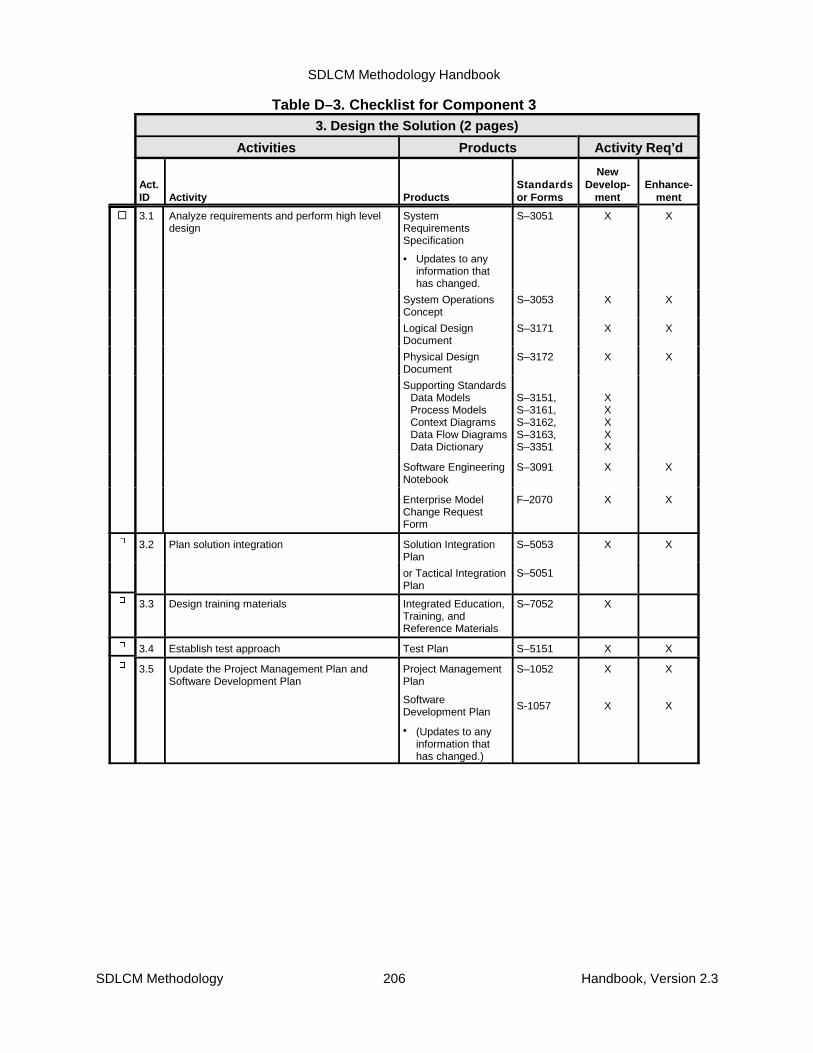
SDLCM Methodology Handbook
SDLCM Methodology 206 Handbook, Version 2.3
Table D–3. Checklist for Component 33. Design the Solution (2 pages)
Activities Products Activity Req’d
Act.ID Activity Products
Standardsor Forms
NewDevelop-
mentEnhance-
ment
� 3.1 Analyze requirements and perform high leveldesign
SystemRequirementsSpecification
• Updates to anyinformation thathas changed.
S–3051 X X
System OperationsConcept
S–3053 X X
Logical DesignDocument
S–3171 X X
Physical DesignDocument
S–3172 X X
Supporting StandardsData ModelsProcess ModelsContext DiagramsData Flow DiagramsData Dictionary
S–3151,S–3161,S–3162,S–3163,S–3351
XXXXX
Software EngineeringNotebook
S–3091 X X
Enterprise ModelChange RequestForm
F–2070 X X
9 3.2 Plan solution integration Solution IntegrationPlan
S–5053 X X
or Tactical IntegrationPlan
S–5051
9 3.3 Design training materials Integrated Education,Training, andReference Materials
S–7052 X
9 3.4 Establish test approach Test Plan S–5151 X X
9 3.5 Update the Project Management Plan andSoftware Development Plan
Project ManagementPlan
SoftwareDevelopment Plan
• (Updates to anyinformation thathas changed.)
S–1052
S-1057
X
X
X
X
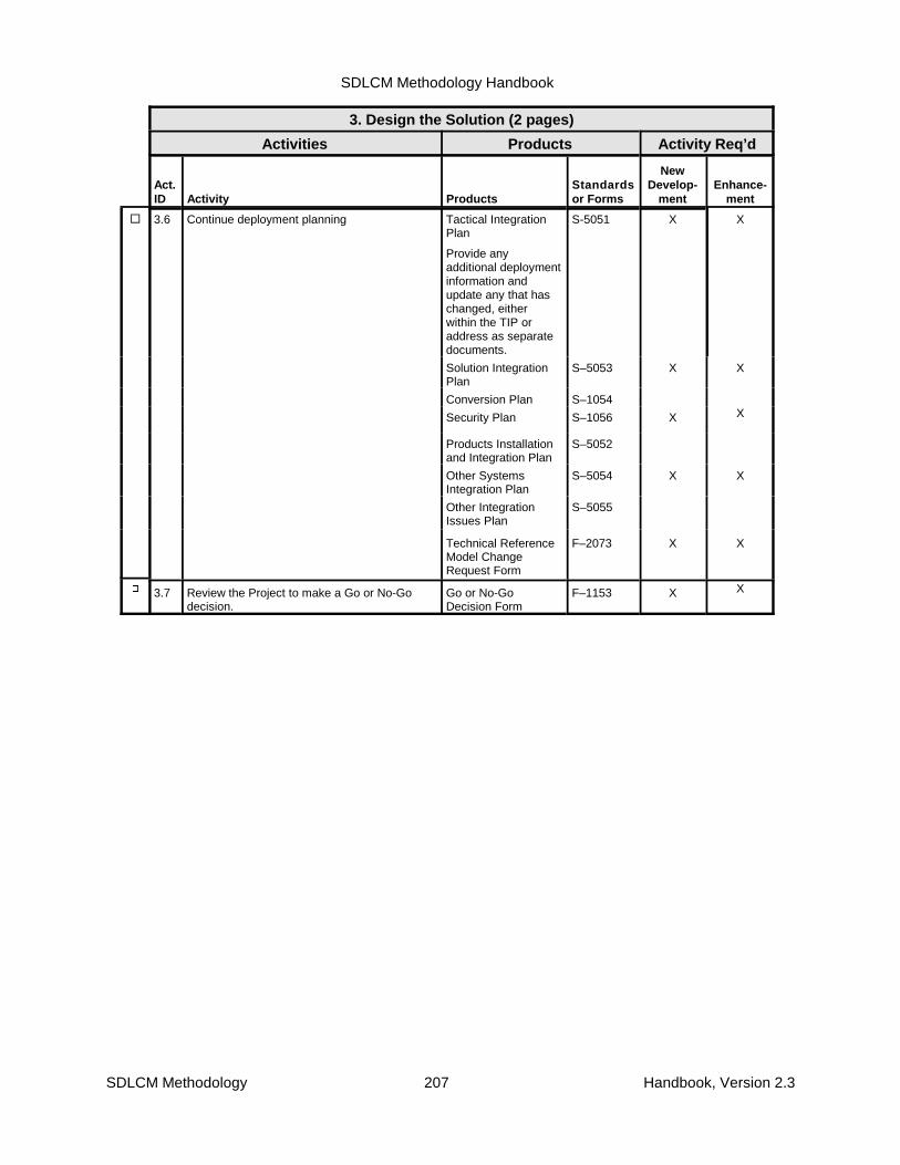
SDLCM Methodology Handbook
3. Design the Solution (2 pages)
Activities Products Activity Req’d
Act.ID Activity Products
Standardsor Forms
NewDevelop-
mentEnhance-
ment
SDLCM Methodology 207 Handbook, Version 2.3
� 3.6 Continue deployment planning Tactical IntegrationPlan
Provide anyadditional deploymentinformation andupdate any that haschanged, eitherwithin the TIP oraddress as separatedocuments.
S-5051 X X
Solution IntegrationPlan
S–5053 X X
Conversion Plan S–1054
Security Plan S–1056 X X
Products Installationand Integration Plan
S–5052
Other SystemsIntegration Plan
S–5054 X X
Other IntegrationIssues Plan
S–5055
Technical ReferenceModel ChangeRequest Form
F–2073 X X
9 3.7 Review the Project to make a Go or No-Godecision.
Go or No-GoDecision Form
F–1153 X X
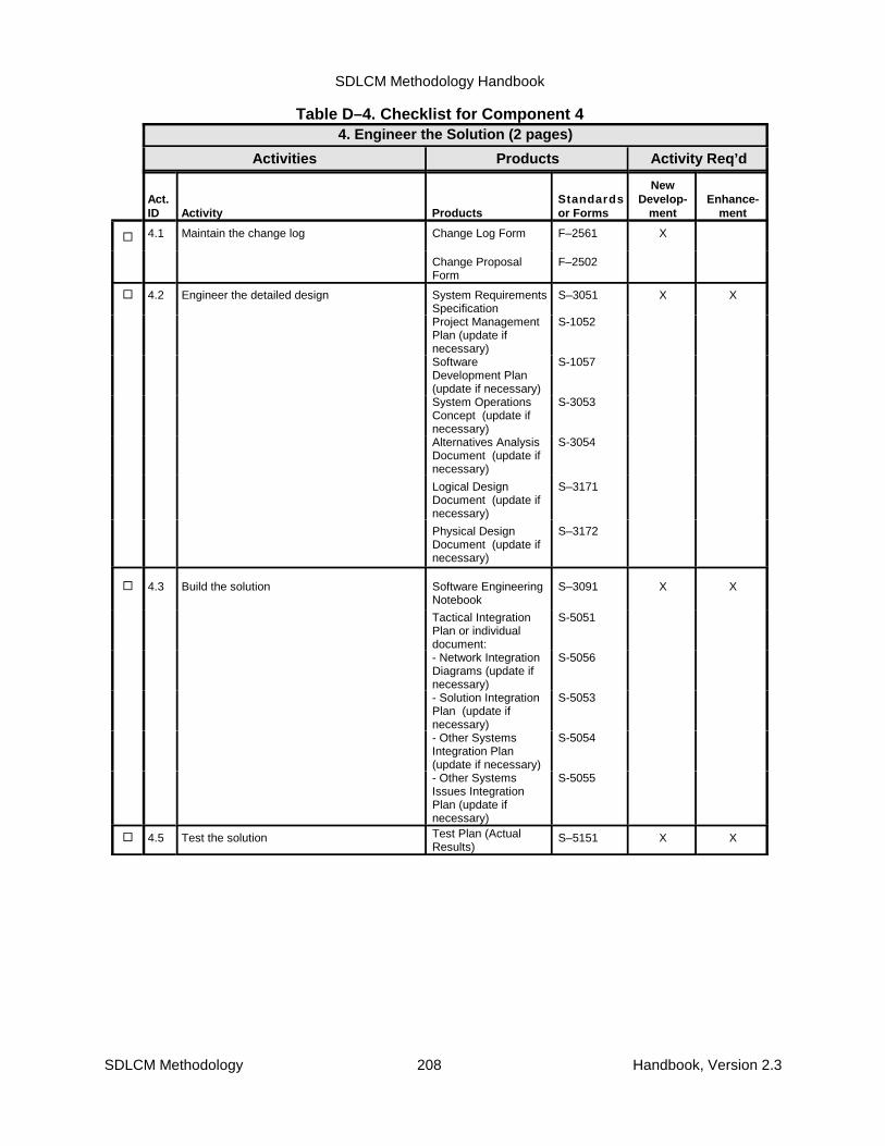
SDLCM Methodology Handbook
SDLCM Methodology 208 Handbook, Version 2.3
Table D–4. Checklist for Component 44. Engineer the Solution (2 pages)
Activities Products Activity Req’d
Act.ID Activity Products
Standardsor Forms
NewDevelop-
mentEnhance-
ment
� 4.1 Maintain the change log Change Log Form F–2561 X
Change ProposalForm
F–2502
� 4.2 Engineer the detailed design System RequirementsSpecification
S–3051 X X
Project ManagementPlan (update ifnecessary)
S-1052
SoftwareDevelopment Plan(update if necessary)
S-1057
System OperationsConcept (update ifnecessary)
S-3053
Alternatives AnalysisDocument (update ifnecessary)
S-3054
Logical DesignDocument (update ifnecessary)
S–3171
Physical DesignDocument (update ifnecessary)
S–3172
� 4.3 Build the solution Software EngineeringNotebook
S–3091 X X
Tactical IntegrationPlan or individualdocument:
S-5051
- Network IntegrationDiagrams (update ifnecessary)
S-5056
- Solution IntegrationPlan (update ifnecessary)
S-5053
- Other SystemsIntegration Plan(update if necessary)
S-5054
- Other SystemsIssues IntegrationPlan (update ifnecessary)
S-5055
� 4.5 Test the solution Test Plan (ActualResults)
S–5151 X X

SDLCM Methodology Handbook
4. Engineer the Solution (2 pages)
Activities Products Activity Req’d
Act.ID Activity Products
Standardsor Forms
NewDevelop-
mentEnhance-
ment
SDLCM Methodology 209 Handbook, Version 2.3
� 4.6 Create the rollout strategy and continuedeployment planning
Tactical IntegrationPlan (Section 2,Rollout Plan)
S–5051 X X
• InstallationInstructions (or asappendix to TIP)
S–5252
• NetworkIntegrationDiagrams (in TIP)
S–5056
• Additional TIPinformation/updatewith changes.
Target UsersCapability UpgradeRequest Form
F–6054
� 4.7 Update Policies and Procedures System InventoryUpdate Form
F-2071 X X
Technical ReferenceModel Update Form
F-2073
GovernmentInformation LocatorSystem Update Form
F-3060
ManagementDirectives, RuleChanges,Procedures, etc.
� 4.8 Build the user material and training materials User Guide S–6051 X X
Online Help Systemand Tutorials
S–6052
Operational SupportGuide
S–6151
User Training andOrientation Plan
S–7053
� 4.9 Deliver the Training User Guide S–6051 X X
Online Help Systemand Tutorials
S–6052
Operational SupportGuide
S–6151
User Training andOrientation Plan
S–7053
� 4.10 Update the Project Management Plan andSoftware Development Plan
Project ManagementPlan
SoftwareDevelopment Plan
S–1052
S-1057
X X
� 4.11 Review the Project to make a Go or No-Godecision.
Go or No-Go DecisionForm
F–1154 X X

SDLCM Methodology Handbook
SDLCM Methodology 210 Handbook, Version 2.3
Table D–5. Checklist for Component 55. Deploy the Solution (2 pages)
Activities Products Activity Req’d
Act.ID Activity Products
Standardsor Forms
NewDevelop-
mentEnhance-
ment
� 5.1 Review and update plans and announcedeployment
Project ManagementPlan
S–1052 X X
Tactical IntegrationPlan
·Updates to anyinformation that haschanged.
S–5051
DeploymentAnnouncement
X X
� 5.2 Validate and upgrade the environment (CurrentEnvironment)
X X
Tactical IntegrationPlan
S–5051
� 5.3 Install the solution InstallationInstructions
Installation ReportForm
S–5254
F–5254
X
X
X
X
� 5.4
5.6
5.10
Test the installed solution
Operational Support System Test
User Test the Solution
(Tested solution) X X
Tactical IntegrationPlan
S–5051
Test Plan (w/TestLog)
S-5151 X X
9 5.5
5.7
5.11
Analyze the Installed System Test Results
Analyze Operational Support Test Results
Analyze the User Test Results
Problem Report Form F–2251 X X
Problem Report LogForm
F–2252
Performance ReportForm
F–5256
DeploymentRecommendationsfor Fix Form
F–5257
� 5.8 Implement policies and procedures System InventoryUpdate Form
F–2071 X
Technical ReferenceModel Update Form
F–2073
GILS Update Form F–3060
(Updated system-specific policies andprocedures)
9 5.9 Train the users Change ProposalForm
F–2502
Problem Report Form F–2251
Trained Users Form F–7151

SDLCM Methodology Handbook
5. Deploy the Solution (2 pages)
Activities Products Activity Req’d
Act.ID Activity Products
Standardsor Forms
NewDevelop-
mentEnhance-
ment
SDLCM Methodology 211 Handbook, Version 2.3
9 5.12 Acceptance test the solution Software EngineeringNotebook
S–3091 X X
CustomerSatisfaction Form
F–6055
DeploymentRecommendation forFix
F-5257
Final User Sign-offForm
F–6056
Change ProposalForm
F–2502
Problem Report Form F–2251
� 5.13 Analyze the Acceptance Test Results Problem Report Form F–2251 X X
Problem Report LogForm
F–2252
Solution ModulesReady forDeployment Form
F–4051
DeploymentRecommendationsfor Fix Form
F–5257
� 5.15 Deploy the Solution Rollout Report
CutoverAnnouncement
F-5255 X
X
X
X
� 5.16 Review Component 5. Go or No-GoDecision Form
F–1155 X X
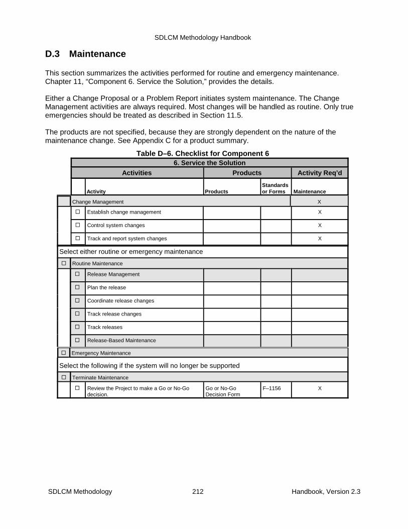
SDLCM Methodology Handbook
SDLCM Methodology 212 Handbook, Version 2.3
D.3 Maintenance
This section summarizes the activities performed for routine and emergency maintenance.Chapter 11, “Component 6. Service the Solution,” provides the details.
Either a Change Proposal or a Problem Report initiates system maintenance. The ChangeManagement activities are always required. Most changes will be handled as routine. Only trueemergencies should be treated as described in Section 11.5.
The products are not specified, because they are strongly dependent on the nature of themaintenance change. See Appendix C for a product summary.
Table D–6. Checklist for Component 66. Service the Solution
Activities Products Activity Req’d
Activity ProductsStandardsor Forms Maintenance
Change Management X
� Establish change management X
� Control system changes X
� Track and report system changes X
Select either routine or emergency maintenance
� Routine Maintenance
� Release Management
� Plan the release
� Coordinate release changes
� Track release changes
� Track releases
� Release-Based Maintenance
� Emergency Maintenance
Select the following if the system will no longer be supported
� Terminate Maintenance
� Review the Project to make a Go or No-Godecision.
Go or No-GoDecision Form
F–1156 X
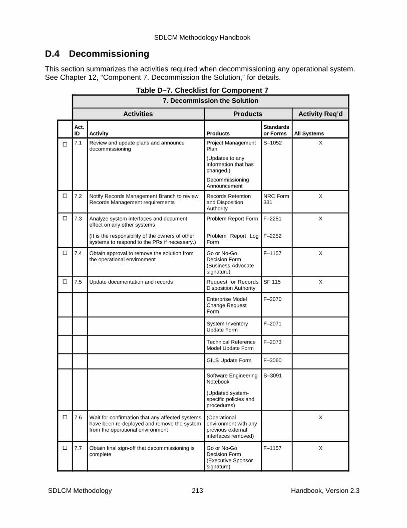
SDLCM Methodology Handbook
SDLCM Methodology 213 Handbook, Version 2.3
D.4 Decommissioning
This section summarizes the activities required when decommissioning any operational system.See Chapter 12, “Component 7. Decommission the Solution,” for details.
Table D–7. Checklist for Component 77. Decommission the Solution
Activities Products Activity Req’d
Act.ID Activity Products
Standardsor Forms All Systems
� 7.1 Review and update plans and announcedecommissioning
Project ManagementPlan
(Updates to anyinformation that haschanged.)
DecommissioningAnnouncement
S–1052 X
� 7.2 Notify Records Management Branch to reviewRecords Management requirements
Records Retentionand DispositionAuthority
NRC Form331
X
� 7.3 Analyze system interfaces and documenteffect on any other systems
Problem Report Form F–2251 X
(It is the responsibility of the owners of othersystems to respond to the PRs if necessary.)
Problem Report LogForm
F–2252
� 7.4 Obtain approval to remove the solution fromthe operational environment
Go or No-GoDecision Form(Business Advocatesignature)
F–1157 X
� 7.5 Update documentation and records Request for RecordsDisposition Authority
SF 115 X
Enterprise ModelChange RequestForm
F–2070
System InventoryUpdate Form
F–2071
Technical ReferenceModel Update Form
F–2073
GILS Update Form F–3060
Software EngineeringNotebook
(Updated system-specific policies andprocedures)
S–3091
� 7.6 Wait for confirmation that any affected systemshave been re-deployed and remove the systemfrom the operational environment
(Operationalenvironment with anyprevious externalinterfaces removed)
X
� 7.7 Obtain final sign-off that decommissioning iscomplete
Go or No-GoDecision Form(Executive Sponsorsignature)
F–1157 X

SDLCM Methodology Handbook
SDLCM Methodology 214 Handbook, Version 2.3
Appendix E. Transition of Legacy SystemsThis appendix summarizes the process for transition of legacy systems from the NRC to acontractor for life-cycle management.
E.1 Systems Developed with SDLCM Methodology Guidance
This section addresses the case in which NRC or a contractor has developed an applicationsystem under the guidance of NRC’s SDLCM Methodology. Under these conditions, when NRCtransitions the application system to a different NRC organization or contractor for maintenanceor enhancement, NRC will provide the system source code plus printed and electronic copies ofall available system documentation, including at least the following:
� System Requirements Specification
� System Operations Concept
� Analysis of Alternatives
� Current System Assessment Document
� Software Engineering Notebooks
� Logical Design Document (The following documents must be included or providedseparately.)
� Data Models
� Process Models
� Context Diagrams
� Data Flow Diagrams
� External Systems Interface Diagrams
� Data Dictionary
� Physical Design Document (The following documents must be included orprovided separately.)
� Data Models
� Process Models
� Context Diagrams
� Data Flow Diagrams
� External Systems Interface Diagrams
� Data Dictionary
� Tactical Integration Plan (The following documents must be included or providedseparately.)
� Operations and Maintenance Plan
� Products Installation and Integration Plan
SDLCM Methodology Handbook
SDLCM Methodology 215 Handbook, Version 2.3
� Solution Integration Plan
� Other Systems Integration Plan
� Other Integration Issues Plan
� Network Integration Diagrams
� Test Plan
� Integrated Education, Training, and Reference Materials
� Operational Support Guide
� User Guide
� On-Line Help System and Tutorials
� Waivers
The organization responsible for supporting the life-cycle management of the applicationsystem will maintain the system documentation to be consistent with changes in theoperational system.
E.2 Systems Developed without SDLCM Methodology Guidance
This section addresses the case in which NRC or a contractor has developed an applicationsystem without the benefits that would have been derived by following the guidance of NRC’sSDLCM Methodology. This situation may arise if the NRC wishes to transition a legacy systemdeveloped prior to NRC’s introduction of the SDLCM Methodology or if a user who is unaware ofthe requirement to adhere to NRC’s mandated system development methodology develops anew system.
Under those conditions, when NRC transitions the application system to a different NRCorganization or contractor for maintenance or enhancement, NRC will provide the system sourcecode plus printed and electronic copies of all available system documentation, including thoselisted if the preceding section, if possible.
A minimal subset of the system documentation is critical for the successful maintenance of anyapplication. Without this minimal subset of system documentation, there is a high risk that themaintenance organization will be unable to satisfy requests for changes to the applicationsystem. If that subset is not available, NRC will fund the maintenance organization to developthe following minimal documentation at the time of transition:
� System Requirements Specification
� Software Engineering Notebook(s)
� Logical Design Document (portions):
� Data Flow Diagrams
� Data Dictionary
� Physical Design Document (portions):
� Data Flow Diagrams
� Data Dictionary
SDLCM Methodology Handbook
SDLCM Methodology 216 Handbook, Version 2.3
� Tactical Integration Plan (portions or optional subdocuments):
� Solution Integration Plan
� Other Systems Integration Plan
� Network Integration Diagrams
� User Guide
Table E–1 summarizes the system documentation required for transition of an applicationsystem and references all of the products listed in Section E.1. For the convenience of thereader, the table also indicates the identifier of the SDLCM Methodology standard that definesthe content of the each product. For potentially complex documents (that is, the SRS, LDD,PDD, and TIP), the table lists sections (or optional subdocuments in the case of the TIP)separately.
The table also indicates the risk that maintenance will not be successful if the documentation isnot provided.
� High. The documentation is required for successful maintenance. NRC must minimallyprovide the indicated products at the time of transition or must fund the maintenanceorganization to develop the products at that time.
� Medium. The documentation is desirable. If it is not provided, NRC will fund developmentof the documentation when is it required for specific maintenance or enhancementactivities.
� Low. The documentation is potentially useful and will be provided to the maintenanceorganization if it is available. Although this documentation is essential when developing anew system, it is unlikely to be essential during maintenance. NRC will fund the creationof the documentation if it is needed for successful maintenance.
E.3 Alternative System Documentation
NRC’s SDLCM Methodology provides an alternative standard to be used only for the case inwhich NRC or a contractor has developed an application system without the benefits that wouldhave been derived by following the guidance of NRC’s SDLCM Methodology. In such asituation, preparing the complete SRS, LDD, and PDD after the application system has alreadybeen developed may not be useful. Portions of those products, although needed during the initialdevelopment of the application, may not be essential for system life-cycle management.
SDLCM Methodology Standard S–4151, As-Built System Documentation, consolidates therequirements and design of an existing system in one product to facilitate the maintenance andfuture enhancement of the application system. A documentation product built to comply with thisstandard contains all of the requirements and design information essential for successfulmaintenance and future enhancement activities. (See the standard for details of the content.) Asthe application system is modified through maintenance or enhancement, the maintenanceorganization will also maintain the as-built documentation to reflect the modified requirementsand design.
A decision by NRC to adopt the As-Built System Documentation for transition of a legacy systemthat was not developed with SDLCM Methodology guidance simplifies the minimal subset of thesystem documentation that is critical for the successful maintenance of an application. Instead ofthe list prescribed in Section E.2, NRC may elect to fund the maintenance organization todevelop the following minimal documentation at the time of transition:

SDLCM Methodology Handbook
SDLCM Methodology 217 Handbook, Version 2.3
� As-Built System Documentation
� Software Engineering Notebook(s)
� Tactical Integration Plan (portions or optional subdocuments):
� Solution Integration Plan
� Other Systems Integration Plan
� Network Integration Diagrams
� User Guide
Table E–1. Documentation Required for System Transition
Project Product Name (specified by NRC’s SDLCM Methodology) Identifier
Risk if not Provided
High Med Low
System Requirements Specification S–3051 �
Current System Assessment Document S–3052 �
Analysis of Alternatives Document S–3054 �
System Operations Concept (SOC) S–3053 �
Software Engineering Notebook S–3091 �
Logical Design Document S–3171 �
Data Models (Logical) S–3151 �
Process Models (Logical) S–3161 �
• Context Diagram (Logical) S–3162 �
• Data Flow Diagrams (Logical) S–3163 �
• External Systems Interface Diagrams (Logical) S–3164 �
• Data Dictionary (Logical) S–3351 �
Physical Design Document S–3172 �
• Data Models (Physical) S–3151 �
• Process Models (Physical) S–3161 �
• Context Diagram (Physical) S–3162 �
• Data Flow Diagrams (Physical) S–3163 �
• External Systems Interface Diagrams (Physical) S–3164 �
• Data Dictionary (Physical) S–3351 �
Tactical Integration Plan (and related sub-documents) S–5051
• (Section 2) Rollout Plan S–5051 �
• (Section 3) Operations and Maintenance Plan S–5051 �
• Conversion Plan S–1054 �
• Security Controls S–1056 �
• Products Installation and Integration Plan S–5052 �

SDLCM Methodology Handbook
Project Product Name (specified by NRC’s SDLCM Methodology) Identifier
Risk if not Provided
High Med Low
SDLCM Methodology 218 Handbook, Version 2.3
• Solution Integration Plan S–5053 �
• Other Systems Integration Plan S–5054 �
• Other Integration Issues Plan S–5055 �
• Network Integration Diagrams S–5056 �
• Installation Instructions S–5252 �
Test Plan S–5151 �
Integrated Education, Training, and Reference Materials S–7052 �
Operational Support Guide S–6151 �
User Guide S–6051 �
On-Line Help System and Tutorials S–6052 �
SDLCM Methodology Handbook
SDLCM Methodology 219 Handbook, Version 2.3
Appendix F. Project Management Overview ofSDLCMM
This appendix is written to present the SDLCMM from the view point of the Overall ProjectManager’s responsibilities. It provides scaling differences that exist between MaintenanceProjects and Development/Enhancement Projects. It also provides information regardingSDLCMM documentation developed during the CPIC Selection Phase that is necessary for theCPIC Business Case development and approval to move forward to the CPIC Project Phase.
F.1 The Overall Project Manager and the Use of the SDLCMM
The Overall Project Manager and his Project Team are responsible for the success of theProject. The Systems Development Life-Cycle Management Methodology (SDLCMM) isestablished as a Handbook which provided guidance regarding controls, decisions, and activitiesfor a generic project. It is supported by a volume containing Standards, Procedures and Forms.
The SDLCMM Handbooks defines seven Components. While the general life-cycle of any Project resulting in a system which includes automation of some or all of the processes, beginswith Definition (Chapter 6 - Component 1) and ends with Decommissioning (Chapter 12 -Component 7), the greater period of time for use of a system is spent in Service/Maintenance(Chapter 11 - Component 6). It is important to note that the reason for defining the SDLCMM in“components” rather than “phases” is because it is more flexible in this format to applying it tothe various Software Development Life-Cycle Models (See Chapter 3 of the SDLCMMHandbook). The Overall Project Manager, is responsible for choosing early in the Project theSoftware Development Life-Cycle Model that will be used for the Project. He makes thisdecision with input from his Project Team, specifically, the Technical Project Manager, based onthe detail level of understanding known of the requirements, the funding approach available forthe project, etc.
The Overall Project Manager is responsible for the planning, management, and oversight of theProject. He does this through effective use of Project Management skills and appropriatedelegations to his Project Team members. He must ensure that the staffing is adequate for thevarious roles necessary to support the Project. A definition of the roles and the responsibilitiesof these roles can be found in Appendix B of the SDLCMM Handbook. While at the beginning ofthe Project the roles of Executive Sponsor and Overall Project Manager may be the only staffedpositions, it is important to note that the SDLCMM provides for planning for and acquiring(Chapter 7 - Component 2) the necessary skills to meet the other roles and responsibilities. The Overall Project Manager should ensure that all resources needed are addressed not justthose that achieved through procurement or contracting. Go/No Go decisions are required evenin Component 2. This means that all commitments for proper staffing should be completedbefore going forward with the Project.
The Project’s requirements will be refined from the initial requirements and systems operationalconcept and will reflect a lower level of detail at the time of design from that known at thebeginning of the Project. For this reason, it is important the Overall Project Manager addresschange management and version control early in the Project so that proper controls are in placeas changes are made. Information on Configuration Management (which includes Change
SDLCM Methodology Handbook
SDLCM Methodology 220 Handbook, Version 2.3
Management and Version Control of products of the Project) is contained in Chapter 5 of theSDLCMM Handbook and the procedure for using a Change Control Board approach is defined inthe Companion Volume as P-2501.
Additionally, the quality of the Project’s products will need to examined throughout the Project toensure a high quality product at the end and traceability back to the original requirements. Information on Quality Assurance is provided in the SLDCMM Handbook in Chapter 4.
A list of the required products and the associated activities is provided in a quick checklist formin Appendix D of the SDLCMM Handbook. This should be reviewed and understood by theOverall Project Manager and any plans to omit specific products or substitute others should beaddressed early on through the submission of a formal Request for Deviation or Waiver from theSDLCMM. The form that is used to document this decision and obtain approval by the Office ofthe Chief Information Officer is F-2010 which can be found in the SDLCMM Companion Volumeof Procedures, Standards and Forms.
The OCIO provides formal training on the SDLCMM and is available to assist Overall ProjectManagers with any questions regarding the Methodology. It is a requirement that Overall ProjectMangers be trained in the SDLCMM and is recommended that all members of the Project Teamreceive training.
In sections that follow there is a discussion of Components 1 through 5 which may be usefulfrom a Overall Project Manager perspective when managing either a development ormaintenance project/effort. It presents in a narrative format the same information provided inthe Handbook Chapters 6 - 10, but provides some additional information related to use of theMethodology for Maintenance activities and the relationship of the activities and products to theCPIC process.
F.2Component Discussions
F.2.1 Component 1
During Component 1, system (or subsystem) concepts are defined and selected, and thetechnical groundwork is laid for the entire Project. This phase may be:
• The initial phase of a development effort
• The beginning of an effort which includes some or all of the following: definition, analysis,design, development/engineering and deployment/delivery of a system, subsystem(s) orcomponents for new installations, or as modification/improvement to an existing system
• A study effort which completes when the requirements are analyzed and results are reported
In any of these cases, SDLCMM Component 1 activities involve reviewing and evaluating Projectsystem requirements and translating them into alternative operating concepts and specifications.All requirements, at all levels, must be reviewed by all appropriate members of the ProjectTeam, especially the Overall Project Manager, Technical Project Manager and BusinessAdvocates, before being incorporated into the Project. Functional analysis, identifying interfaces,

SDLCM Methodology Handbook
SDLCM Methodology 221 Handbook, Version 2.3
synthesis, and analysis/tradeoff studies are the primary Component 1 activities which providethe basis for allocating requirements, developing alternative design concepts, and for refiningthe System Requirements Specification (SRS) in follow-on Components. The SRS contains thebaselined requirements for the system. Component 1 effort completes with a SystemRequirements Review (SRR). The system configuration, including requirements, that isestablished at the SRR represents the Functional Baseline. The procedure and description ofthe SRR is contained in P-2010. Project Team participation and approval at all appropriate levelsand for all disciplines is required in the performance of the SRR.
Formal documentation produced in this component includes: Project Charter (S-1051),preliminary Project Management Plan (S-1052), Current System Assessment Document (S-3052), System Operations Concept (S-3053), System Requirements Specification (S-3051),Configuration Management Plan (S-3501), Quality Assurance Plan (S-2001), SoftwareDevelopment Plan (S-1057), and Analysis of Alternatives (S-3054) for approaching thedevelopment of a solution and identification of support resources needed to proceed with theProject.
Component 1 activities may start as a part of CPIC Selection Phase activities related toresponding to requests for new products and major product enhancements. It may, alternatively,start with a change to an existing system in the form of an adaptive, corrective, preventivemaintenance or a perfective change viewed as a minor enhancement. The specifics of the need,or need for change, must be communicated clearly to all concerned parties and to NRCmanagement in order to make timely and informed decisions. The early efforts called for in theCPIC Selection Phase, including planning (Components 1, 2 and 3), analysis (Components 1and 3), review (Components 1 and 3), and design (Component 3), provide the basis for anaccurate cost estimate and improve the chances for performing to specifications on time andwithin budget.
Projects that require CPIC approval are, typically, development Projects (i.e., new work resultingin a new application system) or enhancement to an existing application system, as opposed tomaintenance efforts where a change, or minor enhancement, is being made to an existingsystem. This section will address the Component 1 process to be performed under each startingscenario but will tie together coordinating activities from Components 2 and 3. The specificComponent 2 and 3 activities will be addressed in more detail in follow-on sections.
F.2.1.1 Starting a Project under CPICWhile the CPIC Selection Phase starts with Component 1, where requirements are defined andanalyzed, it does not end until a Business Case is defined. The definition of the Business Caserequires that activities defined in Components 2 and 3 also be accomplished. Products that willbe completed in Components 2 and 3, which need to be initially addressed on Component 1 at ahigh level, are discussed as well.
In the CPIC Selection Phase, Component 1 defines the requirements by breaking down thestatement of need (information from the CPIC Screening Form) into functional, performance,operational, programmatic, special (accessibility, records, etc) and data requirements; in theComponent 1 activities a definition of the requirements is developed and a concept ofoperations is produced which provides a description of the system. The concept (Systems
SDLCM Methodology Handbook
SDLCM Methodology 222 Handbook, Version 2.3
Operations Concept) is used as a tool to verify that the requirements list (System RequirementsSpecification) is complete and to provide input regarding details of the programmatic use andprocesses from a user perspective when performing Component 3 activities. An additionalComponent 1 activity completed during this CPIC Phase involves performing an analysis ofalternatives for approaching the development of the system that will satisfy the concept andmeets the requirements. This analysis provides initial input to the development of the BusinessCase in the form of initial cost/benefit figures and analysis of the return on investment. Thealternatives analysis generally is conducted on at least three alternatives: staying as is (currentsystem assessment forms this baseline), and two or more other alternatives including suchapproaches as: modifying an existing system, building a new system from the ground up, orusing COTS, etc. Detailed Project Planning is started during the Component 1 effort and isrefined as the requirements are baselined and the Project progresses in Components 2 and 3.Baselining requirements at the end of the Component 1 effort is key to establishment of thefunctional capabilities of the proposed system.
The portions of the CPIC Selection Phase begun during Component 1 are: • Requirements Identification and Definition
• Alternatives Analysis with Cost/Benefit/Risk Analysis
• Development of the Project Management Plan
• Development of a System Operations Concept document
The early Systems Requirements Identification and Definition, Alternatives Analysis, and ProjectPlanning effort is considered a vital stage of the SDLCMM process for hardware/softwaredevelopment or system integration Projects because it is here that the entire Project Team(made up of NRC staff and others, as required, including the Executive Sponsor, BusinessAdvocates and Business Subject Matter Experts) reaches agreement on foundational elementsof the Project prior to actual design efforts. It is a key tenet of the SDLCMM that the personnelexpected to perform the primary roles in the development and acceptance of the applicationsystem are part of the planning effort.
The purpose of the early Systems Requirements Identification and Definition, AlternativesAnalysis, and Project Planning effort is threefold: (1) to allow the Executive Sponsor and theBusiness Advocates to communicate functional, performance, operational, programmatic, andother specific requirements from their own point of view to each other to reconcile terminologyand any conflicting objectives; (2) to document these requirements with definitions and examplesto ensure that they are uniformly understood by the Project Team; and (3) to formulate adetailed plan for accomplishment of the required effort. These requirements expand on the CPICScreening Form inputs and are captured in the initial draft of the SRS, while the planning andscheduling efforts are captured in the PMP and SDP.
Planning efforts set the stage for effective tracking, management and oversight of both therequirements and the actual planned Project effort. During planning, the organization, facilitation,work breakdown structure, program schedule, staffing needs, cost, and detailed plans necessaryfor the Project Team to meet the Project, or Program obligations in a cost-effective manner areestablished. It is imperative that planning be accomplished to ensure that adequate resources

SDLCM Methodology Handbook
SDLCM Methodology 223 Handbook, Version 2.3
and funding are allocated in order to achieve cost effectiveness. During the Needs Analysis andPlanning effort, the bringing together of all Project Team disciplines into a single team causesintegration of efforts to produce a quality product as each follow-on components of the SDLCMMis executed.
Note: It is implicit that the Overall Project Manager ensure that adequate resources andfunding are obtained during the Component 2 effort to accomplish all necessary activities inaccordance with NRC policy.
The goal of the System Requirements Definition and Alternatives Analysis effort is to formallydocument and obtain approval for the system requirements, as expressed and documented inthe SRS; definition and agreement upon a concept of how the system will work; and theapproach that will be taken to bring this system to fruition. The functional requirements for thesystem may be gathered through surveys, statements, feedback on prototypes, problem reportsor interviews, etc. and are expanded into a complete composite set of system requirements(SRS). These system requirements reflect what is needed to support and deliver to the level ofthe system operational concept (SOC) and should be stated in terms of system capabilities,including performance; interfaces with other systems; physical characteristics; user businessknowledge and computer skills; system quality factors, such as reliability, maintainability, andavailability; flexibility and expansion; documentation; logistics; data; and personnel and training.The system analysis also determines the qualification requirements; that is, the qualificationtests that are necessary to verify and validate the system capabilities. The Overall ProjectManager is responsible, during this Component, to develop the User Acceptance test criteriawhich addresses those requirements that must be satisfied for user acceptance of theapplication system.
System Requirements Definition and Alternatives Analysis effort is the first step in the process ofconverting the requirements derived from the initial CPIC Screening Form (Statement of Need) into a combination of system elements which satisfy that need. It involves analysis of existingdocumentation and conducting discussions with the Project Team (Technical InterchangeMeetings (TIMs)) to document agreement on requirements and to refine the purpose and themanner in which the user will operate the system. External interfaces to the system areidentified, as are system capacities. Methods for requirements verification of each requirementstatement are also determined at this point. The process iterates with functional analysis andsynthesis efforts to assess feasibility and to structure to the requirements in the most costeffective manner. This iterative process serves to make the verification process more accurateand cost effective by eliminating ambiguity in the requirement statements. The Project Teamshould also strive to eliminate unnecessary implied design in the requirement statements.
A very large system may require a multi-tiered approach to the System Requirements Definitionand Alternatives Analysis resulting in a system level requirements analysis and multiplesubsystem level analyses. For example, a system may be divided into two or more subsystemswith a requirements analysis being performed at the system and subsystem levels. In this case,the System Requirements Definition and Alternatives Analysis effort will be performed at a levelof abstraction appropriate for a High-Level System Design (see Component 3). The High-LevelSystem Design will identify the subsystems and allocate system requirements to each. Theprocess is then repeated for each subsystem. The input to the System Requirements Definitionand Alternatives Analysis effort for each subsystem then includes high-level system

SDLCM Methodology Handbook
SDLCM Methodology 224 Handbook, Version 2.3
requirements produced by the system level requirements analysis effort. All requirements of theHigh-Level System Design must map to the appropriate subsystem design and to theappropriate identifier for management control within that subsystem. Traceability of all systemrequirements must be documented.
F.2.1.2 Starting Component 1 for a System under MaintenanceMaintenance efforts are changes, minor enhancements and fixes to existing systems(applications and their support environments). Maintenance is a Component 6 (Service theSolution) effort and is explained more fully in Section 11. This section will detail the Component1 related activities associated with maintenance.
A maintenance effort is comprised of a reiteration of the necessary actions from Component 6and Components 1 through 5, but the efforts are separate, i.e., not aggregated as in the CPICprocess where Component 2 and 3 efforts are prerequisites to moving forward. In this scenario,Component 2 and Component 3 are separate efforts.
Maintenance is based upon a documented Change Management process. The ChangeManagement process may be different for different applications/systems, but must bedocumented in order to effect consistency and repeatability. All Component 1 inputs must derivefrom the Change Management process. Inputs generally take the form of a Change Proposal(CP) or Problem Report (PR). PRs and CPs report what needs to be fixed and may report howthe fix should be effected. In any case, the input of the high level need, or definition of theproblem, provides the basis for Component 1 Systems Requirements Definition and AlternativesAnalysis activities. In the case where the CP/PR contain information regarding how the changeshould be made, some, or all, of the Alternatives Analysis effort will have been completed.
Maintenance efforts present the greatest risk of error because the application system is in placeand all changes to it need to be documented and managed so that the application system is notcompromised as a result of the new work. Analysis of the need for change, the definition,coordination and management of the system requirements, and the careful planning of design,test and deployment activities is paramount. Complete testing to ensure that the change hasonly altered the functionality that was intended (regression testing) is of extreme importance inthis regard, specifically when new or changed functionality is introduced. Just as in Developmentefforts (Starting a Project under CPIC), Component 1 activities during a Maintenance effort setthe stage for all of the follow-on efforts by establishing a firm baseline which describes what is tobe reflected in the changed product.
SDLCMM Maintenance scenarios occur under one of three circumstances:
• Release-Based Maintenance
• Minor Enhancement
• Emergency Maintenance
Release-Based Maintenance is the most common instance of a Component 6 Maintenanceeffort. It assumes that periodic, or aperiodic, planned releases will be performed on a given

SDLCM Methodology Handbook
SDLCM Methodology 225 Handbook, Version 2.3
system through a Release-Based Management process. CPs and/or PRs are usuallyaggregated to form the planned deployment, but a release may be comprised of only oneCP/PR. When properly executed, this option presents the lowest level of risk because there is,or should be, the highest level of Systems Requirements Definition and Alternatives Analysis ofthe current system performed. There will also be highest level of planning for makingalternations to the application system, testing it, and coordinating it with the implementationefforts. With the communication of the Project Management Plan (PMP) and SoftwareDevelopment Plan (SDP), if applicable, all concerned or affected entities may be coordinated forrequirements definition/management, engineering effort monitoring, completion and approval ofall appropriate testing (including appropriate regression testing), training development anddelivery and deployment of the updated system.
Minor Enhancement is a “mini” development effort, requires careful definition and managementof requirements to ensure that the product baseline is protected, and presents the greatest riskof missing a step in the SDLCMM process. It does not however, when properly executed,present the greatest risk to the delivered product, simply because it is well planned. This caserequires the most effort because it will transition through all aspects of the SDLCMM define,design, engineer and deploy activities. It is, essentially, a repeat of the process that a CPICProject would use, without the up-front emphasis on building the business case. Care must betaken, at minimum, to consider change to all documentation and to make a case-by-casejudgement as to whether each document needs to be changed/updated. Some documentation isrequired, such as the PMP and TIP, updates to the SRS, and, in later components, LogicalDesign Document and Physical Design Document. Planning for the update of all appropriatedocumentation is a must.
Emergency Maintenance presents the highest risk to the system product due to the need forimmediacy of change. Compromises may be made in the heat of getting a system back on-lineafter experiencing a fault which requires prompt action. In such a situation, it is prudent to makeonly absolutely necessary changes and to place them in a “temporary” location so that they maybe easily removed after more permanent, properly engineered modifications are releasedthrough the release-based maintenance approach, explained above. Sometimes emergencyfixes are effected through “patches” to the code to simplify the process. It is, however, requiredthat the Component 1 Systems Requirements Definition and Alternatives Analysis activities beperformed as soon as possible after system repair. Because actions are usually taken in haste,sometimes without regard to “correctness,” it is crucial that the Maintenance team carefullydocument exactly what was done to address the emergency so that it is easier to assess theSystems Requirements Specification (SRS) and other documentation changes that will need tobe made. It is important that the correct paperwork, i.e., Problem Report (PR), is generated todocument the problem, that the PR be reviewed and approved at all appropriate levels, and thatall appropriate documents, especially the System Requirements Specification, are updated assoon as possible to reflect the modified state of the system. The SRS must be updated as partof the Component 1 Maintenance effort as the functional baseline has changed. There may alsobe a need for regression testing to ensure that the “fix” will not, actually or potentially, causeother problems with the changed, or an interfacing, system.
Component 1 for any scenario in Maintenance includes the Systems Requirements Identificationand Definition, Alternatives Analysis and Project/Effort Planning aspects of the SDLCMMprocess. It focuses on discerning the actual change required, planning the effort to accomplishthe changes, and updating all appropriate documentation to ensure that adequate knowledge is

SDLCM Methodology Handbook
SDLCM Methodology 226 Handbook, Version 2.3
transferred to continue maintenance of the system. The most important outcome of Component1 effort is the maintenance of the functional baseline as reflected in the requirements containedin the SRS. It is, therefore, of extreme importance that attention be given to updating the SRS asearly as possible in the Component 1 Maintenance effort, no matter which scenario.
Component 1 defines the requirements by breaking down the statement of need (informationfrom the Change Proposal (CP)/Problem Report (PR), i.e., new reporting format requirements,description of a problem experienced, etc.) into changes to the functional, performance,operational, programmatic, special (accessibility, records, etc.) and data requirements, whichthen become the updates for the System Requirements Specification. Component 1 thenperforms an analysis of the requirements and produces updates/changes to the SystemOperations Concept. Re-Baselining requirements at the end of the Component 1 effort is key tomaintenance of the functional baseline (full list of satisfied and new requirements to be met bythe application system).
The Systems Requirements Identification and Definition, Alternatives Analysis and Project/EffortPlanning efforts are considered vital in the SDLCMM process for all types of maintenance effortsbecause it is here that the entire Maintenance Team (CLIN Manager, User/Sponsor, andTechnical Subject Matter Experts) begins its planning and definition and analysis of theproposed system changes prior to commencement of the design efforts to effect them. If theChange Proposal (CP)/Problem Report (PR) that is driving the effort has already performed theanalysis and/or defined the design solution, then that analysis/definition must be communicatedand approved by all appropriate parties (CLIN Manager, CCB Chair, etc.) before proceeding. It isalso a key tenet of the SDLCMM that the maintenance personnel expected to perform the taskparticipate in the planning activities of the Component.
The purpose of the Systems Requirements Identification and Definition, Alternatives Analysisand Project/Effort Planning efforts is threefold: (1) to allow the Executive Sponsor and theBusiness Advocates to communicate changes to functional requirements from their own pointof view to each other to reconcile terminology and any conflicting objectives; (2) to documentthese changed requirements with definitions and examples to ensure that they are uniformlyunderstood by the Project Team; and (3) to formulate a detailed plan for accomplishment of therequired effort. The functional requirements discerned and/or expressed at this time may expandon the Change Proposal (CP)/Problem Report (PR) inputs and are captured in the update of theSystem Requirements Specification (SRS), while the planning and scheduling activities arecaptured in the Project Management Plan (PMP) for the maintenance effort. It is very importantto not let the updating of the SRS be neglected in any of the Maintenance scenarios. In the caseof Emergency Maintenance, the “after the fact” conduct of the Component 1 effort, i.e., after theactual fix has been made (even though only temporary), may lessen concern for ensuring thatthe new functional baseline is properly documented.
Planning activities set the stage for effective tracking, management and oversight of therequirements and the actual planned maintenance effort. During planning, the organization,facilitation, work breakdown structure, maintenance/enhancement schedule, staffing needs,cost, and detailed plans necessary for the Maintenance Effort Team to meet the maintenanceeffort obligations in a cost-effective manner are established. It is imperative that planning beaccomplished to ensure that adequate resources and funding are allocated in order to achievecost effectiveness. During the Systems Requirements Identification and Definition, Alternatives

SDLCM Methodology Handbook
SDLCM Methodology 227 Handbook, Version 2.3
Analysis and Project/Effort Planning activities, the bringing together of all Project Teamdisciplines into a single team causes integration of efforts to produce a quality product as eachfollow-on component of the SDLCMM is executed.
Note: It is implicit that the Overall Project Manager (in this case, the individual alsoserving as Contract Office Technical Representative (COTR) or CLIN Manager) ensurethat adequate resources and funding are approved during the Component 2 effort toaccomplish all necessary activities defined in Components 2, 3, 4, 5 and 6 in accordancewith NRC policy.
The purpose of the System Requirements Definition and Alternatives Analysis effort is toformally document and obtain approval for the changed system requirements, as expressed anddocumented in the Systems Requirements Specification (SRS) update; and the approach thatwill be taken to bring this maintenance effort to fruition. The changed system requirementsinclude updates to the system operational concept (SOC) and should be stated in terms ofsystem capabilities, including performance; interfaces with other systems; physicalcharacteristics; system quality factors, such as reliability, maintainability, and availability;flexibility and expansion; documentation; logistics; data; and personnel and training. There is aneed here for requirements to be prioritized and that criteria be defined for qualification tests thatare necessary to verify and validate the changed system capabilities, as well as regressiontesting, to ensure that unchanged capabilities are intact.
System Requirements Definition and Alternatives Analysis is the first step in the process ofconverting the requirements derived from the initial Change Proposal (CP)/Problem Report (PR)into a combination of system elements which satisfy that need. It will involve analysis of existingdocumentation and may include conducting discussions with the Project Team (TechnicalInterchange Meetings (TIMs)) to document agreement on changed/new requirements and torefine the purpose and the manner in which the end-user will utilize the system. Externalinterface changes are identified, as are system capacity changes, as applicable. Methods forverification and test of each changed/new requirement statement are also determined at thispoint. The process may iterate with functional analysis and synthesis efforts to ensure successof the maintenance effort through the verification process and by eliminating ambiguity. TheMaintenance Effort Team should also strive to eliminate unnecessary implied design.
F.2.2 Component 2
The purpose of the Acquire Support Resources Component is to take action to develop andexecute appropriate acquisition methods to secure the identified resources from Component 1,3, 4, 5, 6 and 7. While activities within Component 2 may begin concurrent with activities withinComponent 1, these activities may not finish until after the Systems Requirements Review andGo/No Go Decision are completed for Component 1. Additionally, since the Methodology isComponent based, rather than phase based, this Component may be revised each timeComponent 1, or other Components, identify additional resources (personnel, equipment,software, etc.).
Formal documentation produced in this Component includes updates to the ProjectManagement Plan (S-1052), Tactical Implementation Plan (S-5051), Software Development Plan(S-1057). Formal documentation developed during this Component may include: Development
SDLCM Methodology Handbook
SDLCM Methodology 228 Handbook, Version 2.3
and Maintenance Environment Products Installation Plan (S-1055) and one or more Statementof Work (S-1053). Statements of Work may address the acquisition of such items as: training ofdevelopment staff in new tools; training for users prior to testing and/or implementation of theapplication systems; hardware and software for the development environment; hardware andsoftware for the operational environment; editors, writers, etc. needed to document policy andprocedures; contractor services for the design phase of the application development; contractorservices for the engineering and deployment phase of the application development; contractorservices for the operational support phase of the application life cycle.
Component 2 may start as being part of the CPIC Selection Phase activities related toresponding to requests for new products and major product enhancements. It may, alternatively,start with an adaptive, corrective, or perfective (minor enhancement) change under amaintenance effort.
F.2.3 Component 3
The purpose of the Design the Solution Component (Component 3) is to allocate the baselinedsystem requirements to manual or automated processes and, if automated, to the hardware andsoftware approaches envisioned as the solution set for the automated system. The systemdesign decisions (Logical Design Document and Physical Design Document) made in thiscomponent have a major affect on subsequent components. For software development projects,this component identifies and defines the process paths through the system that input (stimuli ortransactions) to the system would take to provide an output (responses or transaction results).These process paths are documented as Process Models. Through the mapping ofrequirements to defined processes and the identification of creation, receipt, storage, deliveryand reporting points for data, further documentation is produced which defines Data (DataModels and Data Dictionary) and captures business rules. The initial planning activities fortesting, training, integration and deployment are begun in Component 3 and result in a numberof documents being started in this component (Tactical Integration Plan, Test Plans andscenarios, Solution Integration Plan, Integrated Training and Education and ReferenceMaterials, etc.). Initial decisions regarding the appropriate levels of testing and when and whoshould participate in these tests are made during this component.
Formal documentation reviewed and updated in this component may, as necessary, includeupdates to:
• Project Management Plan (S-1052)
• Alternative Analysis Document (S-3054)
• System Requirements Specification (S-3051)
• System Operations Concept (S-3053)
• Software Development Plan (S-1057)
Formal documentation requirements for Component 3 includes a review of:
• Configuration Management Plan (S-3501)
SDLCM Methodology Handbook
SDLCM Methodology 229 Handbook, Version 2.3
• Quality Assurance Plan (S-2001)
• Current System Assessment Document (S-3052)
Formal documentation requirements for Component 3 also includes drafting of the Test Plan (S-5151), planning for the development of the Training and Operational Support products, as wellas completing the baseline of both the Logical Design Document (S-3171) and Physical DesignDocument (S-3172).
Note: Baselining the Logical Design Document and Physical Design Document includesgeneration or update and baselining of:
• Data Models (S-3151)
• Process Models (S-3161)
• Context Diagrams (S-3162)
• Data Flow Diagrams (S-3163)
• Data Dictionary (S-3351)
Changes identified that affect the System Requirements Specification (S-3051), at this point, willbe handled through the Change Control process since that document has been previouslybaselined and now resides in the Project-Level Configuration Management Library. The designleads to a better assessment of cost, schedule, and risk, which input to the CPIC business case.The CPIC business case is submitted at the end of this Component. With the completion of thisComponent and submission of the CPIC business case, the Project must now halt to awaitapproval to enter the CPIC Project Phase.
F.2.3.1 Component 3 under CPICComponent 3 activities are a part of the CPIC Selection Phase activities related to responding torequests for new products and major product enhancements. Alternatively, Component 3activities are also a part of non-CPIC level enhancement and maintenance activities which startwith a change to an existing system in the form of an adaptive, corrective, preventive or minorenhancement change.
If this Component 3 effort is part of a CPIC Selection Phase, the activities may initially befocused on defining the design to the point that a business case with sufficient confidence in thedefinition of the cost and schedule can be presented for approval. After Project Phase approval,a verification of the design is accomplished in Component 4 to ensure that the design is still solidand that there have been no changes in requirements or other perturbations that affect the finaldesign. The start of planning for integration and deployment, and generation of the TIP, are alsoaccomplished in this Component. The design becomes baselined at the System Design Review(SDR) as all parties review and approve it to move to development in the Engineer the Solutioneffort, Component 4. Baseline of the design and completion of the SDR also are essential tobegin the CPIC Project Phase.
In a development effort, once the transition is made to Component 4, prototyping, computermodeling and/or testing may be undertaken to determine if the best design concept was actually

SDLCM Methodology Handbook
SDLCM Methodology 230 Handbook, Version 2.3
chosen in the Component 3 design effort. This ensures that the critical elements can meetoperational and support requirements, and, if indicated, allows return to Component 3 forrefinement of the design concept.
F.2.3.2 Component 3 under MaintenanceIf Component 3 is part of a Maintenance effort, activities will either focus on validating a solutionthat may have been supplied with the Change Proposal/Problem Report (CP/PR) that started themaintenance effort or on designing a solution to satisfy the need expressed in the correspondingCP/PR. The design becomes baselined at the System Design Review as all parties review andapprove it to move to development in the Engineer the Solution component, Component 4.
F.2.3.3 Component 3 Either CPIC or MaintenanceThis Component utilizes documentation products developed in other components asfoundational documents to perform the actual design of a system to the point of approval fordevelopment. The initial objective of the component is validating the system functional baselineby establishing that it is complete and consistent. The second objective is to develop candidatearchitectures (designs, hardware platforms and vendor tools (COTS), selecting those which canfulfill the requirements within cost and schedule constraints.
Note: In very large systems where a multi-tiered approach has been taken to SystemRequirements Analysis, resulting in a (High-Level) system requirements analysis andmultiple (Lower-Level) subsystem analyses, the design process will be iterated for eachsubsystem. Extra care must be taken in these cases to ensure integrity of the system.Thus, interface requirements and design take on more importance. All requirements ofthe High-Level System Design must map to the appropriate subsystem design and to theappropriate lower level code or hardware solution within that subsystem. Traceability ofall system requirements must be documented.
Conceptual design efforts and studies and tradeoffs of the alternatives are continued and/orrefined until the requirements are synthesized into firm system design concepts. The resultingplanned discrete pieces of the system (Configuration Items (CIs)) are documented in the LogicalDesign Document (LDD), Physical Design Document (PDD), Process Models (PM), Data Models(DM), Context Diagrams (CD), Data Flow Diagrams (DFD) and Data Dictionary (DD). Trainingand Operational Support materials are also to be included in the items developed and/orupdated in this Component. The Software Development Plan (SDP) and other required softwaredocumentation are delivered, or updated and delivered, as applicable.
Configuration Items (CIs) are the building blocks for a system, each uniquely identifiedand documented with its functional and physical characteristics. CIs provide the basis forapplying management controls to a system configuration, permitting the isolation of itemsto be controlled, the tracking of status, and the reporting of configurations. CIs may takedifferent forms:
• Software artifacts - the software CI is the architectural construct of the softwaresystem
• Hardware artifacts - the hardware CI is the architectural construct of the hardware

SDLCM Methodology Handbook
SDLCM Methodology 231 Handbook, Version 2.3
system
• Documentation artifacts - Documents, which describe CIs and configurations ofCIs (baselines), may be CIs themselves
Note: The Configuration Management Office (CMO), in cooperation with systemsengineering, establishes a scheme for the unique identification of each configuration itemto be controlled for the Project/effort. Configuration baselines are the documentation thatformally designate/identify the aggregation of CIs that constitute the system at anyspecific time. Configuration baselines, plus approved changes to those baselines,constitute the current approved configuration documentation. There are generally fourformally designated baselines in the development life-cycle of a system, namely theFunctional, Allocated/Design, Engineering, and Operational/Product baselines.Maintenance activities apply changes to the previous Operational/Product baseline tocreate the current Operational/Product baseline. Like named baselines are distinguishedfrom one another through assignment of unique version designators. Additionalinformation concerning configuration identification is contained in Section 5.2.
The component completes with a System Design Review (SDR), which determines whether thesystem is ready to proceed to the next Component in the SDLCMM process, the Engineer theSolution Component. Successful completion of Component 3 constitutes the Design/Allocatedbaseline. The start of planning for integration and deployment, and generation of the TIP, shouldalso have been accomplished in this Component. Overall Project Manager, Executive Sponsorand Technical Project Manager review, approval, and sign off (Go/No Go Decision) for alldisciplines at all appropriate levels is required at the SDR.
In Component 3, focus is directed toward:
• The organization/design of the system
• Definition of the data and associated business rules
• Definition of the processes
• The interaction among elements of the system
• Designing the system to meet performance, functional, and operational requirements
• Designing the system to meet reliability requirements
• Defining the cost and schedule for building, implementing and performing initialmaintenance of the system
• The adaptability of the system to potential future requirements
These points constitute the realization of the system concept, which was defined earlier (theSystem Operations Concept, a Component 1 product) as a model of the system that defines thefunctional approach and the generic techniques that are to be used to achieve the prescribedperformance. The portions of the system defined in the system design and the architecturesproposed for them (COTS, hardware products, custom code, etc.) are examined together toachieve the best performance of the system. This component produces a system architecture,

SDLCM Methodology Handbook
SDLCM Methodology 232 Handbook, Version 2.3
designed in detail and built as a set of independent portions/processes for subsequentintegration into the completed, or updated/changed (for the maintenance case), system.
System Integration, Training, and Test Planning activities and the development and delivery ofmaterials defined through these planning activities take place concurrently with System Designand continue to be addressed until full System Integration and Testing is completed inComponent 5.
The Test Plan, which is begun in this Component, defines the planned test phases (i.e., unit test,software integration test, system test, user test, performance, systems integration test,acceptance test, etc.), assigns the verification tasks to the appropriate test phase, and lays outthe organizational responsibilities in performing each test. These tests need to address allrequirements defined for the system, both automated and manual. Further, they should ensurethat user knowledge of the business area requirements are addressed if data value choices arenot automated. It describes the test program at both high and low levels, levies requirements onthe technical content of test plans and procedures, and establishes the criteria for verification ofrequirements.
The Test Plan must contain inputs from all disciplines that will be using and supporting thesystem. The Project Manager must ensure that this Test Plan does not represent only the inputfrom the Project Technical Lead and his contractor. The Test Plan, by necessity, must includeinputs from every concerned entity to ensure that all requirements are addressed in one or moretests and at all appropriate levels of test. Traceability of each system requirement to one or moretests must be documented. Review, understanding and approval is tantamount to ensuring acomplete comprehensive testing program.
F.2.4 Component 4
The purpose of the Engineer the Solution Component is to move the allocated baseline ofrequirements and the (Component 3) design that was developed to address these requirementsinto reality by building, integrating, documenting, testing and preparing the solution fordeployment. Component 4 takes a, possibly, preliminary design and carries it to the point whereit is ready for final testing and user acceptance testing before deployment. Also included in thiscomponent’s effort are construction of all necessary policy, procedures and guidance for boththe automated and non-automated aspects of the system addressing business knowledge anduse of the automated functions which include preparation of the training materials to ensure:
• That the user understands how to use the application system
• That those who are responsible can operate the system
System artifacts and documentation are completed to ensure that the personnel who aredesignated to later support and service the application systems are provided sufficientinformation to perform their functions. As is the case with all components of the SDLCMM, NRCinvolvement and approval at all appropriate levels and at all appropriate times is required.
Formal documentation produced in this component may, as necessary, include updates to the

SDLCM Methodology Handbook
SDLCM Methodology 233 Handbook, Version 2.3
schedule in the Project Management Plan (S-1052) and Software Development Plan (S-1057),updates to the System Operations Concept (S-3053), Test Plan (S-5151), Logical DesignDocument (S-3171), Physical Design Document (S-3172). During this Component, other criticaldocumentation is written: Operational Support Guide (S-6151), User Training and OrientationPlan (S-7053), User Guide (6051), On-Line Help System and Tutorials (S-6052), NetworkIntegration Diagrams (S-5056), entries are made to the Software Engineering Notebook (S-3091) and any necessary Rule Changes, Management Directives and business area functionalguidance documents are developed and approved. This Component also includes extensivedocumentation work in the testing arena as the testing strategy gels. All planned levels of testmust be planned and step-by-step procedures developed for conduct. Unit Testing, ApplicationSystem Integration Testing, and Single Node Performance Testing is conducted. Test Reports,prepared post-test, are required to ensure traceability and communication that all systemrequirements, as baselined in the SRS, are satisfied.
Component 4 may be the first effort in the CPIC Project Phase but, at this point in the SDLCMMprocess, there are no special considerations for the CPIC process other than reporting back tothe Overall Project Manager through the Technical Project Manager for the IT allocated portionsand, as directed by the Overall Project Manager, for the manual approach portions of theallocated baseline. At a minimum, reporting consists of providing a status on whether theschedules and costs are within the bounds of the estimates and a projection on any effects toschedule and costs to ensure that problems are identified and addressed early. In this regardthere are no differences between how this Component is viewed by a CPIC Project versus theMaintenance case.
The sequence of events in Component 4 is:
• Maintain the Change Log
• Design Validation (if not already completed)
• Design refinement (if not already completed)
• Code and Unit Test
• Integration and Test
• Create Rollout Strategy and Continue Deployment Planning
• Build the Users Manual
• Policies, Procedures and Training Materials Updated/Developed
• Update the Project Management Plan
• Review and Transfer Project Products to Central Configuration ManagementOrganization
Each of these elements is accompanied by appropriate documentation and traceability to thesystem requirements.
F2.4.1 Maintain the Change LogConfiguration Change Control is the systematic proposal, justification, evaluation, coordination,

SDLCM Methodology Handbook
SDLCM Methodology 234 Handbook, Version 2.3
approval or disapproval, and implementation of changes to Configuration Items (CIs), theplanned discrete pieces of the system. The objective of Configuration Change Control is topreserve the integrity of controlled work products and the documentation associated with them.Configuration Change Control begins with the initial release of an item within a baseline, andcontinues throughout a product’s life cycle including the operations and maintenance phases.Design changes are documented through the use of the Change Proposal Form (F-2502) andare logged in the Change Proposal Log Form (F-2561) as a record keeping and changemanagement tool. It is the initiation and maintenance of that log that is the thrust of this activity.
Formal Configuration Change Control must have been established within each system to governall changes and implemented at the Project level.
• No other method will be accepted for proposal of changes.
• "Formal" means "with a form" and with a specific review and approval process. The"form" may be electronic; the key is that there be auditable records of actual review andapproval.
• Authority for change rests with the NRC; authority may be delegated, but responsibilitycannot be delegated.
All requests must comply with defined change control requirements:
• Name and organization of requester
• Identification of configuration item/system to be changed
• Identification of other configuration items/systems which may be impacted
• Description of change
• Reason for change
• Date needed
Configuration Change Control processing is carried out through an aggregation of ProblemReports (PRs)/Change requests (CPs) and Configuration Control Boards (CCBs). PRs/CPs arecompleted to document all problems and changes. CCBs are convened to review perceivedproblems and proposed changes in order to decide if the problem is real or the change isneeded, and to approve or disapprove proposed solutions.
F.2.4.2 Design ValidationThis Section applies to projects/efforts for which the allocation of system requirements amongCIs, design decisions and any associated downstream make/buy decisions are completelysubject to the analysis and engineering judgment of the Project team, as approved by the NRC.In certain cases, however, some, or all, allocation, design and make/buy decisions have alreadybeen made earlier in the effort, either in the CPIC Selection Phase or in the CP/PR that sparkedthe Maintenance effort. Make/buy decisions are made in Component 1 and would necessitate arevisit of Component 1 by the Project Team should the need occur here.

SDLCM Methodology Handbook
SDLCM Methodology 235 Handbook, Version 2.3
In a development effort, once the transition is made from Component 3 to Component 4,prototyping, computer modeling and/or testing may be undertaken to determine if the bestdesign concept was actually chosen in the Component 3 design effort. This ensures that thecritical elements can meet operational and support requirements, and, if indicated, allows returnto Component 3 for refinement of the design concept. In effect, this event would extend thescope of the CPIC Selection Process into Component 4 and necessitate the use of a CriticalDesign Review at the extended end of the design effort as the gateway to the CPIC ProjectPhase.
For the requirements allocated to a IT delivery approach, the purpose of the Design Validationstep is to validate, if not already complete, a complete set of engineering requirements for eachspecific Configuration Item (CI). The requirements set includes functional, performance andgeneral design (e.g., availability, safety, security, etc.) requirements as decomposed andallocated from the system-level requirements specification and derived and allocated from thesystem-level architectural design definition. These requirements are documented in the LDD,PDD and the Test Plan (TP) and any implications reported for entry into the SDP and PMP to bereported. A complete set of CI qualification requirements is also documented in the LDD/PDD.Activities during the Design Validation effort include:
• Validate for each CI the detailed engineering requirements allocated or derived from theSRS
• Validate for each CI the qualifications and methods needed to ensure that the CIs satisfythe requirements allocated to them
• Validate the requirements of any database to be used in common by more than one CI
• Validate the interface requirements for each interface external to each CI.
In the case of a Maintenance scenario, this activity may not be necessary unless a “designsolution” accompanies the PR/CP that initiates a Maintenance effort. If a design is included inthe PR/CP, then validation of that design, as described for a development effort, is required tothe appropriate extent.
When present, Design Validation ends with a review, which may be formal or informal. It isprudent to plan to conduct reviews, as required during this effort, to ensure completecommunication of Project and product status to all entities concerned. Most reviews in thiscontext will be informal and in the form of Peer Reviews and/or Walkthroughs, but may includeformal reviews as required or specified. When this effort is included in CPIC Selection Phaseactivities, the Critical Design Review (CDR) is the review gateway. All requirements, at all levels,must be reviewed by all appropriate organizational entities before being incorporated into theproject.
For the requirements allocated to a manual approach, an analysis of the steps necessary to betaken to perform the work and deliver products that are called for (i.e., written policy,procedures, Management Directives, Training and Testing of Users in Business Principles, etc.)is conducted, assignments for work products are made and documented, and schedules aredefined. Responsibility for creating this information rests with the Overall Project Manager.
SDLCM Methodology Handbook
SDLCM Methodology 236 Handbook, Version 2.3
F.2.4.3 Design RefinementThe Design Refinement effort is used to define the architecture and detailed design for eachConfiguration Item (CI) based on specified requirements, to develop designs for the interfacesspecified and to partition the system into modules and define the design of each, to develop adesign for any shared databases, and to develop a plan for testing the software against therequirements specific to the type of test and category of testing agreed to in the SoftwareDevelopment Plan and Project Management Plan. In certain cases, however, some, or all,design decisions have already been made earlier in the effort, either in Component 3, which is apart of the CPIC Selection Phase or in the CP/PR that sparked the Maintenance effort.
The detailed design effort is used to identify and design all the Computer Software Units (CSUs)that will comprise each Computer Software Component (CSC) within each Configuration Item(CI). The design is developed in sufficient detail to permit coding of the individual CSUs (i.e.,programs, scripts, etc.). In addition to the design activities, CSU and CSC test requirements,responsibilities and schedules are defined (unit and process stream/sub-system testing). Testcases are defined for the informal CSU and CSC tests by developer/integrator. Test cases aredeveloped for each of the formal CI tests identified in the Test Plan (TP) by the integrator. Userdocumentation (i.e., User Guide, User Training and Orientation Plan, Operational SupportGuide, Tutorials, etc.) are updated by Users with new information developed during this effort.Also during this step, the data base to support code and debug activities is allocated so that thedata base can be certified ready for Code and Unit Test. Data bas allocation is as defined in theData Models and is placed on the Development Test servers. In addition, the design ofengineering software and procedures required to populate the production data base for deliveryis developed.
During this effort, all required certifications for user business knowledge testing and full systemtesting scenarios (written from a business process perspective) are developed and documented.Additionally, training criteria for business area knowledge testing, new procedures and policytesting, etc. are defined and training programs and tests are are developed to address thiscriteria. Further, during this effort Business Advocates and Stakeholders define test scenariosand test data for the full system and the Overall Project Manager ensures that Acceptance Testscenarios and data are defined, matching the criteria defined in Component 1. The OverallProject Manager, or his designee, has the responsibility to ensure that the documentation, testdata, and training materials cited in this paragraph are completed.
In the case of a Maintenance scenario, this activity will entail generation of the “design” of thesolution or refinement of the “design solution” that may have accompanied the PR/CP thatinitiated the Maintenance effort. The design, in any case, must be integrated with the existingsystem to ensure that it introduces no adverse effects into the system. If a design is included inthe PR/CP, then refinement of that design, as described for a development effort, is required tothe appropriate extent.
When present, Design Refinement ends with a review, which may be formal or informal. It isprudent to plan to conduct reviews, as required during this effort, to ensure completecommunication of Project and product status to all entities concerned. Most reviews in thiscontext will be informal and in the form of Peer Reviews and/or Walkthroughs, but may includeformal reviews as required or specified. When this activity is included in CPIC Selection Phase,the System Design Review is the review gateway. All requirements, at all levels, must be

SDLCM Methodology Handbook
SDLCM Methodology 237 Handbook, Version 2.3
reviewed by all appropriate organizational entities before being incorporated into the project.
F.2.4.4 Build the SolutionBuild the Solution is a Code and Unit Test activity which implements and tests the softwarewhich reflects the implementation of the design developed during the Design Component (andapplicable refinement) and approved at the System Design Review (SDR) and/or Critical DesignReview (CDR). The purpose of the Code and Unit Test effort is to produce and test each CSUdefined in the detailed design for the Configuration Item (CI). Each CSU is reviewed forcompliance with its corresponding detailed design description and applicable coding standardsprior to establishing internal configuration control of the CSU and releasing it for integration.Additionally portions of these activities include developing detailed procedures for conductingeach informal CSU and Computer Software Component (CSC) integration test. CI and build testprocedure generation is begun and will be completed during the CSC Integration and Testingeffort. There is no formal review during Code and Unit Test, but it is prudent to plan to conductreviews, as required, to ensure complete communication of Project and product status to allentities concerned. Most reviews in this context will be informal and in the form of Peer Reviewsand/or Walkthroughs, but may include formal reviews as required or specified. The outputs fromthis effort include the source code listings, source code, and the Procedures portion of thetesting documentation. This activity ends with the Test Readiness Review (TRR).
In a Maintenance scenario, implementation of the design may range from trivial to extremelycomplex. In any case, the appropriate level of coordination and planning for Code and Unit Testmust be completed. In most cases, this will entail careful planning for coding and regressiontesting to ensure continued integrity of the system.
F.2.4.5 Integration and TestThe purpose of the Integration and Test activity is to integrate and test the application systemsoftware and is considered the first formal test. Testing here concentrates on verifying that thedeveloped (implemented) CI meets the requirements specified in the SRS and is representativeof the Concept of Operations defined by the Project Team in Component 1. Where applicable,CSC testing is performed to aggregate modules or units before aggregating CSCs for integrationinto CIs. Verification in this instance means to establish the correspondence between a softwareproduct and its specification. This testing process is performed during the development cycleand can begin as early as when the code is developed and may extend to the end of Integrationand Test. It is complete when all CSCs and CIs have been successfully tested in accordancewith the appropriate test plan (formal test scenarios and procedures).
Computer Software Component (CSC) Integration and Testing is used to perform a series ofbuilds and tests to verify that a Configuration Item (CI) is complete and ready for formal testingby the full Project Team and the Users and Operations Support Staff who will be responsible forrunning the system in production. CSCs are aggregated using a cycle of build, build test andintegration test. Builds, in this context, are aggregations of CSCs that represent a definedfunctionality, structure, or scenario and are sometimes the entry point for new ComputerSoftware Units (CSU) into Project Configuration Management. Builds are generally performed bya dedicated build team using the baseline configuration contained in the CM library. Integrationtests determine by functional, structural, statistical, and regression testing that the softwareperforms correctly, generates expected results, and handles errors appropriately. The CSCIntegration and Testing effort is iterative and may overlap Code and Unit Test. CSC Integration
SDLCM Methodology Handbook
SDLCM Methodology 238 Handbook, Version 2.3
and Testing can begin as soon as groups of CSUs making up CSCs are available in theDevelopment Configuration. The outputs from this activity include the tested DevelopmentConfiguration and updated SENs for each CSC and CSU. Test reports document each testresult.
In a Maintenance scenario, integration and testing of the changed portions of the system mustinclude the appropriate level of coordination and planning to ensure continued integrity of thesystem.
When all Engineering effort is complete, with all entities integrated and successfully tested,Component 4 is ended. The Engineering Baseline is established at this time as the basis forSystem level and acceptance testing with the customer organization. Traceability of all systementities (CIs), and the testing thereof, to the system requirements must be maintained anddocumented.
F.2.4.6 Create Rollout Strategy and Continue Deployment PlanningThe purpose of this activity is for engineering, program and/or operations personnel who areinvolved in the building and using of a system to describe the integration of the hardware andsoftware components that comprise the system for final deployment in the customer’senvironment. It entails researching and deciding how, where and when the system will bedeployed, what the precedent actions are with respect to the environment and creating astrategy for putting the system in place.
After determination of the target user community, an assessment of the software/hardwareplatforms, configurations and environments will reveal the need for upgrade, customizationand/or replacement. Those things considered, a schedule for preparation of the environment canbe completed before actual installation and rollout of the system. The results of this planningeffort are documented in an update of the Tactical Implementation Plan.
In a Maintenance scenario, it is most important to maintain continuity between the existing andthe new system in terms of operability. To achieve that end, emphasis must be placed oninterface with the existing users to ensure that system, operational and environment changesare communicated and that appropriate training is conducted in advance of rollout and/ordeployment.
F.2.4.7 Build the Users ManualThe Build the User Manual activity encompasses not only putting together the actual UserGuide, but assembling the User Training and Orientation Plan and developing a CustomerSupport Center.
The User Guide is targeted for personnel who actually use the software, i.e., execute theapplication, to perform their job. The User Guide is both a training and a reference resource. Theeffort that results in production of the User Guide also produces the Help System, OperationalGuide, and Tutorials.
Knowledge of the target operational system and the requirements to support that system are

SDLCM Methodology Handbook
SDLCM Methodology 239 Handbook, Version 2.3
melded together to define the Customer Support Center. The Customer Support Center hasresponsibility for servicing the user after training as s/he uses the system in the true operationalsetting.
Overall training plans and strategies are developed from knowledge of the operational system,the known skill set of the user and other training materials. From this information, the UserTraining and Orientation Plan is assembled to assess the skills of the users, to tailor a trainingprogram for the target users, to evaluate resource needs to effect the training and to assess theeffectiveness of training. Update of User Manuals, training and interface are most important inthe case of a Maintenance effort.
F.2.4.8 Policies, Procedures and Training Materials Updated/DevelopedAfter an analysis of the NRC’s current policies and directives related to the business areas andprocesses supported by the application system design, develop or update to ensure that theysupport the business processes and rules as envisioned in the design and Systems OperationalConcept. It is important at this point to begin the development of user training materials for usein actual training. Training should address both the manual and automated process that makeup the system, as well as business knowledge of the user. This Activity ensures that all policiesand procedures that are the basis for work flows and business rules defined to the applicationsystem and presented in user training are in fact updated and ready for publication. Oncetraining materials are developed, actual training of business process users may begin in both theautomated and manual operations arenas for both development and maintenance efforts.
Updated policies and procedures will be finalized, published and fully implemented prior todeployment in Component 5.
F.2.4.9 Update the Project Management PlanBased on the activities in this component and the documents generated, it is important to nowgo back and update the PMP in preparation for Component 5 activities. The documents thatbecome inputs for the PMP update are shown in Activity 4-8.
F.2.4.10 Review and Transfer Project Products to Central Configuration ManagementOrganizationReview the results of the activities that were performed in this Component to determine if thesystem should be moved forward to Pre-Deployment/Final Testing. Subject Matter Experts in thearea of Records Management and the Infrastructure, along with the Technical and OverallProject Managers, should be involved in this review activity to ensure that all aspects of thesystem and the data are reviewed and commented on from those unique subject perspectivesand that the system is acceptable to move forward. If approved (Go/No Go Form), all the releaseartifacts are delivered to the Central Configuration Management Organization to audit andcheck-in prior to start-up of Component 5 activities.
F.2.5 Component 5
The purpose of the Deploy the Solution Component is move the baselined product into

SDLCM Methodology Handbook
SDLCM Methodology 240 Handbook, Version 2.3
production. This requires ensuring that the product is ready for deployment, the user knows howto use the system, the operator knows how to care for the system, and the environment is readyfor the system. This is accomplished by performing system level testing (includes integration andoperational performance testing such as threshold and throughput), user testing, andacceptance testing (user and operational support) before actual deployment of theapplication/system. It includes delivery of the training to:
• Ensure that the user understands how to use the automated application system and isproficient in the business rules which defines the way in which the application system isused.
• Operator support training which ensures that such actions as backup, recovery, softwareinstallation, and user access are understood and Operations Support Guides arereviewed for accuracy prior to deployment.
It also includes, where necessary, making upgrades to the infrastructure environment andtransferring data from old systems. It ends with the actual deployment of the new system.
As is the case with all components of the SDLCMM, NRC involvement and approval at allappropriate levels and at all appropriate times is required. However, unlike other Componentswhere a single Go/No Go decision is made, this Component requires two:
• A decision on deployment
• A decision on whether the development team will maintain the deployed version of thesystem for a set period of time, usually resulting from an approach that calls for a phaseddelivery of the system, or it the application will be transferred to the maintenancecontractor, which means a Go/No Go decision to Component 6. (This decision is moot inthe case of a maintenance effort since the system is already in maintenance.)
Formal documentation produced in this component includes preparation of the productdeployment announcement, updates to any of the Plans and other documents, and extensivedocumentation work in reporting test results and update of the technical inventory. All plannedlevels of test must be executed using the step-by-step procedures developed for their conduct,as documented in the Test Plan and scenarios. Post-test Test Reports are required to ensuretraceability and communication that all system requirements, as baselined in the SRS, aresatisfied.
Note: In general, this section describes the process that is followed when executing aCPIC initiated effort. A maintenance effort requires evaluation at each step to tailor theeffort for the particulars of the intended release. There is no less rigor employed in themaintenance effort, but there is also no need to expend unnecessary effort for a lesscomplex release. This section describes the full process, with notes and explanations forconsideration in tailoring the process for a maintenance effort.
The sequence of events in Component 5 is:
SDLCM Methodology Handbook
SDLCM Methodology 241 Handbook, Version 2.3
• Review and Update of Plans and Announcement of Deployment
• Validation and Upgrade of the Operational Testing Environment
• Installation, System Integration Test and Evaluation
• Operational Support System Level Training, Test, and Evaluation
• Implement Policies and Procedures
• Training of the Users
• User Testing and Evaluation
• Acceptance Test and Evaluation
• Validation and Upgrade of the Production Environment
• Cutover and Deployment
• Update of Technical Inventory
Each of these elements is accompanied by appropriate documentation and traceability to thesystem requirements.
F.2.5.1 Review and Update of Plans and Announcement of DeploymentReview the Project Management Plan and TIP, and prepare announcement for the upcomingdeployment. The announcement should address information that ensures that all concernedpersonnel are aware of the implementation of the new system capabilities/changes and thateach person (user, operator, manager, etc.) understands the overall and individual impact. It isimportant to prepare people to expect deployment activities. See Activity 5.1. Thisannouncement will be deployed to all interested and/or concerned parties in accordance with theschedule defined in the Project Management Plan, which has a schedule dependency linked tosatisfactory Acceptance Testing (Activity 5.12).
F.2.5.2 Validation and Upgrade of the Operational Testing EnvironmentCare must be taken at this point to ensure that each of the testing environments is conducive tothe testing activity which it must support. Validate each environment and make necessarychanges to ensure successful testing prior to deployment. See Activity 5.2.
F.2.5.3 Installation, Application System Integration Test and EvaluationThis activity is geared more toward a full (CPIC) development effort, but is important, to theextent applicable, for a maintenance effort in that the correct level of integration is accomplishedto ensure that changed elements do not adversely affect the system. This action sets the stagefor regression testing in the maintenance case.
The Application System CIs are installed in the proposed operational environment. ApplicationSystem Integration Test and Evaluation activity takes place after the CIs (discrete portions of theapplication system) have been integrated and tested. Application System Integration and Testencompasses software, hardware and firmware. This activity is concerned with the integration

SDLCM Methodology Handbook
SDLCM Methodology 242 Handbook, Version 2.3
and testing of the CIs to ensure that the interfaces between CIs, or combinations of them thatmake up sub-systems, are properly connected and to verify those requirements that can not beverified without an integrated system.
The purpose of the Application System Integration Test and Evaluation activity is to integrate theaggregate CIs into the end product system by conducting subsystem level integration of CIs intoCI subsystems and integrated subsystems against the requirements of the SRS, then integratingsubsystems into system segments or into a full system configuration. Test and audit of thesystem is conducted for responsiveness to documented functional and physical requirements.Various test scenarios, including end-to-end testing scenarios and, as applicable, integrationtesting should be utilized to test the Application System processes and functionality.
Application System Integration Testing activities will occur in the Consolidated Test Facility(CTF) which is a "lab type" integration facility. Inputs to this activity are the applicable Test Plansections, including step-by-step procedures for each intended scenario. The output of thisactivity is the System Test Report (STR). See Activities 5.3, 5.4 and 5.5.
F.2.5.4 Operational Support System Level Test and EvaluationOperational Support System Level Testing and Evaluation entails activities that are required toconduct technical product acceptance testing from an operation support perspective. This typeof testing is critical to perform prior to user acceptance and deployment of the applicationsystem. This is where the final technical verification of the application system is performed.Operational Support personnel are instructed on the application system and its components andoperational support requirements. These personnel are provided with an Operational SupportGuide which addresses such tasks as backup, recovery, and installation. Verification addressestesting against system performance, operational, and security requirements. Throughput andthreshold tests are performed. The application systems ability to address requirements forsecurity, backup and recovery, and installation into the infrastructure are tested and evaluated.Further, there is a level of full infrastructure integration (cohabitation) testing conducted. Anevaluation of document usefulness and accuracy is performed against the Operational SupportGuide, the Installation Instructions, etc. At the end of this testing and evaluation, all componentsof the application system product/operational baseline (documents, code, executables,integrations, software and hardware) are expected to be ready for deployment.
F.2.5.5 Implement Policies and ProceduresThis Activity centers on ensuring that all policies and procedures identified and updated inComponent 4, which are the basis for work flows and business rules defined to the applicationsystem and presented in user training, are, in fact, finalized, published and implemented.
F.2.5.6 Training of the Users Users must be thoroughly trained in the use of the application system and possess a certifiedlevel of knowledge regarding the business area supported by the application system. Trainingplan and training materials developed earlier in the SDLCMM are used to schedule and presentthis training. Certification testing may be conducted to ensure that Users are knowledgeable inthe business areas and appropriately familiar or trained in the Policies and Proceduresdeveloped in Activity 5.8.

SDLCM Methodology Handbook
SDLCM Methodology 243 Handbook, Version 2.3
F.2.5.7 User Testing and EvaluationTesting of the application system from a user perspective is conducted using both users certifiedin the business area and those who are not. Validation of the adequacy and ease of use of thePolicy and Procedures, User Guide and On-Line Help and Tutorials is conducted and results arerecorded and evaluated. Improvements to training, policy, procedures and the applicationsystems are captured through a Change Proposal and Problem Report approach and evaluatedalong with test results.
F.2.5.8 Acceptance Test and EvaluationUsing the criteria defined by the Sponsor for acceptance of the application system and capturedas scenarios to the Test Plan, the Project Sponsor and his designees conduct the AcceptanceTest against the technically accepted application system. Results of these test scenarios arecaptured and evaluated as part of the User Satisfaction Determination and the Go/No GoDecision. Documentation of these decisions must be completed after all of these levels of testinghave been conducted and there has been a determination of resolution for outstanding issues.With the Go/No Go Decision made to move forward, the cut-over and deployment activities canbe pursued.
At the end of these activities, test results and any updated documents are gathered for deliveryto CCM for use in completing the conduct of the final Functional and Physical Audits prior todeployment. This activity is completed after successful conduct of the Cutover ReadinessReview (CRR). The first Go/No Go decision is made at this point and documented by approval ofthe Solutions Modules Ready for Deployment Form (F - 4051). The announcement ofdeployment can now be published. All testing information is delivered to the Central CMOrganization for their use in completing the Functional Configuration Audit. The Central CMOrganization provides the necessary artifacts for the deployment to the appropriate parties afterthese audits are completed and the audits are favorable for deployment.
F.2.5.9 Validation and Upgrade of Production Environment, Cutover and Deployment ofApplication SystemThe purpose of the Validation and Upgrade of Production Environment, Cutover andDeployment of Application System Activities are to take any necessary steps needed to preparethe production environment (installing upgrades and vendor production) and to prepare priorapplication systems data or copy control tables, etc. for use in the new application system orrelease, and to release the application system, as supplied by the Central CM Organization, intothe production environment. The observation of its performance in actual operation, andgeneration of necessary changes through the CM change control process continue intoComponent 6 activity or into continued maintenance activities under the development contract.CPIC Projects require that a report be submitted on Lessons Learned after 6 months ofoperation.
This Component ends with the delivery of the product into production. Detailed guidance for theconduct of Deployment activity is contained in Activity 5.15. Activity context for Production andDeployment is shown in Figure 10-1
If maintenance of the application system is transferred to another contractor or contract under
SDLCM Methodology Handbook
SDLCM Methodology 244 Handbook, Version 2.3
the second Go/No Go decision, the Project shall be closed out in accordance with appropriateclose-out procedures or as specified in Project Management directives.
SDLCM Methodology Handbook
SDLCM Methodology 245 Handbook, Version 2.3
Appendix G. GlossaryAcquire Support Resources. SDLCM Methodology Component 2, whose purpose is to obtain the necessary resources to ensure timely and effective progress on the Project.
Activity. A unit of work that has well-defined entry and exit criteria. Activities can usually be broken into discrete steps.
Application System. A discrete set of information resources organized for the collection,storage, processing, retrieval, maintenance, use, sharing, dissemination, or disposition ofinformation.
Baseline. A document or set of documents, code, executables, etc. that makes up a system.After a baseline is established, the Nuclear Regulatory Commission (NRC) must approve allchanges prior to their incorporation. Three discrete baselines exist in a Development Project:Requirements/Functional, Design/Allocated, and Operational. Operational baselines aresurrendered to Central CM prior to testing.
Build. A version of software that meets a specified subset of the requirements that thecompleted software will meet. (See also release.)
Component. 1. One of the seven structural divisions of the SDLCM Methodology. 2. A module(See module.)
Computer software component (CSC). A logical subdivision of a computer softwareconfiguration item (CSCI). CSCs are a distinct part of a computer software configuration item. CSCs may be further decomposed into other CSCs and to yet smaller computer software units(CSUs).
Conceptual data model. One of the three data models; identifies groupings of data important tothe business situation that the Project addresses. (See also logical data model, physical datamodel.) The Conceptual data model represents the level of detailed knowledge of systemrequirements and design known prior to the completion of Component 3. The level of knowledgeknown at the completion of the Design (end of Component 3) is reflected in the Logical datamodel and a preliminary Physical Data Model. The Conceptual data model is a preliminaryLogical data model.
Conceptual process model. One of the two process models; also known as the scope-settingversion of the logical process model. (See context diagram. See also logical process model.)The Conceptual process model represents the level of detailed knowledge of systemrequirements and design known prior to beginning the design activities in Component 3. Thelevel of knowledge known at the completion of the Design (end of Component 3) is reflected inthe Logical Process Model. The Conceptual process model is a high-level, preliminary LogicalProcess Model.
Configuration audit. The mechanism for verifying the system configuration. Configurationaudits should address the examination of the system against the functional requirements and theSDLCMM required products (physical). Configuration audits are conducted on the system atboth the Project Level and Central Configuration Library Level by the Configuration Managementpersonnel.

SDLCM Methodology Handbook
SDLCM Methodology 246 Handbook, Version 2.3
Configuration identification. The application of a formal set of procedures to select CIs,determine the documentation required for each CI, affix unique identifiers to the documentationthat defines the CI, release CIs and their associated documentation, and establish configurationbaselines for each CI.
Configuration item (CI). System component (for example, hardware CI or software CI) that isdeveloped or purchased, controlled, accepted, and maintained separately from other systemcomponents. In practice, it is a component that is convenient and sensible to document andcontrol as an entity. (See software configuration item.)
Configuration management (CM). The application of a formal set of procedural concepts bywhich a uniform system of configuration identification, control, authentication, and statusaccounting is established and maintained for a system. These procedures are documented for aProject through the development of the Configuration Management Plan.
Configuration status accounting. The recording, monitoring, and reporting of all changes toestablished baselines for each CI. The purpose of configuration status accounting is to recordand report all information needed to manage configuration items effectively. The objective ofconfiguration status accounting is to ensure that all approved changes for a CI are reflected inassociated baselines that describe the CI and that no baseline includes any changes that havenot been approved.
Context diagram. A top-level data flow diagram that names the system to be developed ormodified and that defines the bounds of a system in terms of the data it receives and generates.(See conceptual process model, data flow diagram.)
COTS (or GOTS) software. Commercial (or government), off-the-shelf software. COTS andGOTS software includes (1) unique components that must be delivered with the product toexecute the operational software and (2) development tools that must be delivered with theproduct to support maintenance of the software.
CPIC - Capital Planning and Investment Control. A policy of the NRC to ensure thatinformation resource investments are planned, selected, managed and evaluated to maximizethe value and minimize the risks of those investments, in accordance with Federal statutes andregulations (M.D. 2.2)
Data flow diagram. A logical graphical representation of the data that are processed andgenerated during system operations.
Data model. (See conceptual data model, logical data model, and physical data model.)
Decommission The Solution. SDLCM Methodology Component 7, whose purpose is toinactivate and cease support of an application by appropriately addressing the RecordsDisposition Schedule conditions of the system.
Define Initial Project Requirements. SDLCM Methodology Component 1, whose purpose is toidentify an information management problem, clarify scope, identify functional and datarequirements, analyze alternative solutions, select appropriate tools, establish a ProjectManagement Plan, and develop a support resource request.
Deploy the Solution. SDLCM Methodology Component 6, whose purpose is to implement androll out the integrated solution.
Design. Those characteristics of a system, including its associated hardware and software CIs
SDLCM Methodology Handbook
SDLCM Methodology 247 Handbook, Version 2.3
that respond to the requirements (see requirements). Some will match the requirements; otherswill be elaborations of requirements, such as definitions of all error messages in response to arequirement to display error messages; still others will be rules, policies and procedures forsupport of manual data and process actions, including identification, collection, etc.; decisions onhow processes and data logic will be used, etc. to satisfy the requirements.
Design The Solution. SDLCM Methodology Component 3, whose purpose is to determinefunctional, data, and communications or network requirements, document user interfacerequirements, design the solution, develop necessary enabling rules, procedures, policy,directives, etc. and prepare integration and Project plans.
Development. Production of a new product that leads to delivery of all initially planned functionalcapability. The new product may be built from newly created components, reused components(with or without adaptations), GOTS components, and COTS components. (Contrast withenhancement, maintenance.)
Deviation. A departure from a requirement, an alteration of an activity defined by a procedure,or a variation in the production of a product defined by a standard. (Contrast with waiver.)
Documentation. A collection of data, regardless of the medium (or media) on which it isrecorded, that generally has permanence and can be read by humans or machines. Thesignificance of this definition is that documents do not necessarily have to be separately boundentities; they may comprise data in several media (for example: plans, data models, outputsfrom CASE tools, databases).
Effort. A defined and structured application of the SDLCMM to respond to maintenance changeproposals or emergency fixes. The word effort is differentiated from the word Project in that aunique reportable schedule and budget are not subject to CPIC review, report and oversight.
Engineer the Solution. SDLCM Methodology Component 4, whose purpose is to construct oracquire all modules of the system, perform tests, create the rollout strategy, and construct thetraining and education materials
Engineering change. A change to the currently approved configuration documentation of aconfiguration item at any point in the life cycle of the item. Generally, these are documented on aChange Proposal and approved through an established Project-level Change Control Board.
Enhancement. A major addition or change in the functionality of an operational system; oftenincludes many of the same activities as new development. Generally, reported to and controlledthrough the CPIC process. (Contrast with new development, maintenance; see also softwareengineering.) Minor enhancements are treated as perfective maintenance.
GOTS software. (See COTS software.)
Inspection. A process whereby products are reviewed for correctness, completeness, quality,and compliance with requirements and standards. The process is carried out by one or morepeers of the product’s developer. (Contrast with walkthrough.) Inspections, their frequency andresponsibility for conducting them are documented in the Project’s Quality Assurance Plan(QAP).
Joint application design (JAD). A facilitated workshop technique that brings together principalstakeholders to solve a well-defined problem to produce a well-defined product or set ofproducts.

SDLCM Methodology Handbook
SDLCM Methodology 248 Handbook, Version 2.3
Life cycle. (See system life cycle.)
Life-cycle model. A framework on which to map activities, methods, standards, procedures,tools, products, and services (for example, waterfall, spiral).
Logical data model. One of the three data models; the completed version that presents a fullyattributed and normalized data model and identifies the relationships among all data entities.(See also conceptual data model, physical data model.) The Logical Data Model improves uponthe Conceptual data model by further defining the data model based on the allocated datarequirements. The Logical Data Model represents the data in a model which reflects theunderstanding of the data and its use, from a design standpoint, at the close of Component 3.
Logical process model. One of the two process models; the completed version that providesall the details required to document and communicate to the business community the Projectteam’s understanding of the functional requirements of the application system. (See alsoconceptual process model.) The Logical Process Model represents the level of detailedknowledge of system requirements and design known prior to completing the design activities inComponent 3. The level of knowledge known at the completion of the Design (end ofComponent 3) is reflected in the delivered system.
Maintenance. Implementation of problem fixes and minor enhancements to an operationalproduct, also called Servicing the Solution and documented in the SDLCMM under Component6. (Contrast with new development, enhancement)
Method. A technique or approach, possibly supported by procedures and standards, thatestablishes a way of performing activities and arriving at a desired result.
Methodology. “A collection of methods, procedures, and standards that defines an integratedsynthesis of engineering approaches to the development of a product.” [Paulk]
Milestone review. A process or meeting involving representatives of the Project team and theparties assigned specific roles which produce products at which Project status, product status,and both Project and product issues are examined and discussed.
Module. A cohesive group of software units that performs a software function.
Non-developed item (NDI). A component that is not newly created by the software team. Thisincludes reused components, COTS and GOTS components, and components developed byother government groups or contractor personnel.
Physical data model. One of the three data models; the design model, which describes howdata will be distributed to different processing nodes and structured to meet performanceobjectives in a specific physical implementation. (See also conceptual data model, logical datamodel.)
Procedure. A written description of the roles, responsibilities, and steps required for performingan activity or a subset of an activity. (Contrast with standard.)
Process. “A sequence of steps performed for a given purpose; for example, the softwareengineering process.” [IEEE 610.12]
Process Model. (See conceptual process model, logical process model.)
Product. Software, procedures, rules, policy/directives, models, documentation and otherassociated information created, modified or incorporated to satisfy the requirements of a Project
SDLCM Methodology Handbook
SDLCM Methodology 249 Handbook, Version 2.3
or Effort. (Examples include plans, requirements, design, code, databases, test information andmanuals.)
Project. A resource investment that is subject to the CPIC controls. A Project consists of thework to be done and the personnel assigned to perform the work. Products are produced withina Project.
Prototype. An early experimental model of a system, system component, or system functionthat contains enough capabilities for it to be used to establish or refine requirements, or tovalidate design concepts.
Qualification testing. Testing performed to verify and demonstrate (often to the customer) thata software CI or a system meets its specified requirements.
Release. 1. A build that is delivered to the customer. (See build.) 2. An action performed by theconfiguration management organization making a particular version of software available for aspecific purpose (for example, for independent testing, or for installation into the productionenvironment).
Requirement. A characteristic that is initially defined in Component 1 which defines a specificneed for a system to deliver a capability, operational function, programmatic function or data.
Service The Solution. SDLCM Methodology Component 6, whose purpose is to maintain,enhance, or modify an existing application or its support environment.
Software engineering process. An organized set of activities performed to translaterequirements and operational concepts into software products.
Software engineering. A set of activities that results in software products. Software engineeringincludes new development, modification, reuse, reengineering, maintenance, or any otheractivities that result in software products.
Software product. Software or associated information created, modified, or incorporated tosatisfy the software requirements. Examples include plans, requirements, design, code,databases, test information, and manuals.
Software product evaluation. Activities performed by the software team to ensure that in-process and final software products meet criteria established for those products.
Software Development team. The group, led by the Technical Project Manager, responsible forengineering software products that automate specific system requirements (including newdevelopment, modification, reuse, reengineering, maintenance, or any other activity that resultsin software products).
Software test environment. The facilities, hardware, software, firmware, procedures, anddocumentation needed to perform qualification, and possibly other, testing of software. Elementsmay include but are not limited to simulators, code analyzers, test plan generators, and pathanalyzers, and may also include elements used in the software engineering environment.
System transition. The set of activities that enables responsibility for system engineering topass from one organization, usually the organization that performs system development, toanother, usually the organization that will perform operational support and maintenance.
Standard. Written criteria used to develop and evaluate a product or to provide and evaluate aservice.

SDLCM Methodology Handbook
SDLCM Methodology 250 Handbook, Version 2.3
System life cycle. “The period of time that begins when a system is conceived and ends whenthe system has been decommissioned.
Timebox. A subdivision of a release created to achieve a unit of production that is manageablein size, complexity, staffing, and duration. It is a planning construct that controls functionalitydelivered by fixing resources and time.
Version. An identified, documented, and controlled collection of automated and manualprocesses that make up a system, its associated data structures, procedures, policies anddocumentation. Any change to a version and its associated documentation and data structuresrequires a configuration management action.
Waiver. The elimination of a specific requirement to perform an activity or to produce a product.(Contrast with deviation.)
Walkthrough. Detailed technical presentation of a limited aspect or portion of a product. Suchpresentations are usually made by the product’s developer.

SDLCM Methodology Handbook
SDLCM Methodology 251 Handbook, Version 2.3
AcronymsAAD Alternatives Analysis DocumentBPR Business Process ReengineeringCCB Configuration Control BoardCCM Central Configuration ManagementCDR Critical Design ReviewCI Configuration ItemCIO Chief Information OfficerCLIN Contract Line ItemCM Configuration ManagementCMO Configuration Management OfficeCMP Configuration Management PlanCOTS Commercial Off-The-ShelfCP Change ProposalCPIC Capital Planning and Investment ControlCSAD Current System Assessment DocumentCSC Computer Software ComponentCSCI Computer Software Configuration ItemCSU Computer Software UnitDFD Data Flow DiagramDM Data ManagementFCA Functional Configuration AuditGILS Government Information Locator SystemGOTS Government Off-The-ShelfGSA General Services AdministrationIRM Information Resources ManagementIT Information TechnologyJAD Joint Application DesignLDD Logical Design DocumentNDI Non-Developed ItemNRC Nuclear Regulatory CommissionOCIO Office of Chief Information OfficerOIRM Office of Information Resources ManagementPAL Process Assets LibraryPCA Physical Configuration AuditPCM Project Configuration ManagementPDD Physical Design DocumentPFD Process Flow Diagram

SDLCM Methodology Handbook
SDLCM Methodology 252 Handbook, Version 2.3
PMP Project Management PlanPR Problem ReportQA Quality AssuranceQAP Quality Assurance PlanRFPA Request for Proposal ActionRM Records ManagementSDIB Systems Development and Integration BranchSDLCM System Development and Life-Cycle ManagementSDLCMM System Development and Life-Cycle Management MethodologySDP Software Development PlanSDR System Design ReviewSEN Software Engineering NotebookSME Subject Matter ExpertSOC System Operations ConceptSOW Statement of WorkSQA Software Quality AssuranceSRS System Requirements SpecificationSSR Software Specification ReviewTBD To Be DeterminedTIP Tactical Integration PlanWBS Work Breakdown Structure

SDLCM Methodology Handbook
SDLCM Methodology 253 Handbook, Version 2.3
References[IEEE 610.12] ANSI/IEEE-STD-610.12-1990, “IEEE Standard Glossary of Software
Engineering Terminology,” February 1991.
[ISO/SEC 12207] ISO/SEC 12207, “Software Life-Cycle Processes.”
[MIL-STD-498] MIL-STD-498, “Software Development and Documentation.
[NRC MD2.5] NRC Management Directive 2.5, “Application Systems Life-CycleManagement,” Draft, January 1997.
[NRC SH1.1] NRC OIRM/SDIB, SDLCM Methodology Handbook, Version 1.1, November1996.
[NRC SH2.0] NRC OCIO/ADD, SDLCM Methodology Handbook, Version 2.0, December1997.
[NRC SH2.2] NRC OCIO/ADD, SDLCM Methodology Handbook, Version 2.2, December1999.
[Paulk] Paulk, M., et al., Key Practices of the Capability Maturity Model, Version 1.1,Software Engineering Institute, Carnegie Mellon University, CMU/SEI-93-TR-25, February 1993.