system five user manual for software version 1.9.x ge vingmed ultrasound
TRANSCRIPT

System FiVeUser Manual forSoftware Version 1.9.x
GEVU P.No.: FA092423
GEVU Revision:L
GEMS Cat.No.: H44701VA
GE Vingmed Ultrasound
CAUTION: Federal law restricts this de-vice to sale by or on the or-der of a physician.
Verify the System Software version as shown on page 35

GE Vingmed Ultrasound
Intro-2 User Manual - FA092423 L - System FiVe - sw. 1.9.x

GE Vingmed Ultrasound Introduction
User Manual - FA092423 L - System FiVe - sw. 1.9.x Intro-3
System FiVe
MANUAL STATUS © Copyright 1996 – 2000 by GE Vingmed Ultrasound AIS.
Printed in Norway.eleventh edition, Sept-2000.
All rights reserved. No part of this Manual may be reproduced, stored in a retrieval system, or transmitted, in any form or by any means, electronic, mechanical, photocopying, recording, or otherwise, without the prior writ-ten permission from GE Vingmed Ultrasound AIS.
COMPANY DATA:
GE Vingmed Ultrasound A/S, P. O. Box 141,N-3191 Horten, Norway.
Telephone: +47 3302 1100 Telefax: +47 3302 1350 WWW: http://www.geultrasound.com/
Caution: Product Name labels, Colors, Op-tions, Specifications and Configu-rations described in this manual may vary in different geographical markets.Please contact the local represen-tative for more details.

Introduction GE Vingmed Ultrasound
Intro-4 User Manual - FA092423 L - System FiVe - sw. 1.9.x
INTRODUCTION
GE Vingmed Ultrasound
GE Vingmed Ultrasound is ISO 9001 (1994) and EN 46001 certified. Copies of the certifi-cates are available on request.
System FiVe
System FiVe is an Ultrasound Diagnostic System for applications such as Adult, Pediatric and Neonatal Cardiac, Peripheral Vascular, Abdominal and Ob-Gyn. (See: Indications for use, page 207.)
Probes
The System FiVe allows the use of various probes. Refer to a Probe / Application overview list on page 208.
User Interface
The System FiVe has an intuitive yet flexible user interface philosophy. All the tools are readi-ly available when needed.
Operating Modes
The system controls operate the following modes: Color Flow, 2-D Image, Color M-Mode, M-Mode, HPRF Doppler, LPRF Doppler and CW Doppler, or a combination of these, positioned on the operating panel.

GE Vingmed Ultrasound Introduction
User Manual - FA092423 L - System FiVe - sw. 1.9.x Intro-5
System FiVe’s User Manual
Using this manual:• The TOC of this manual contains, in the or-der from front to rear, the heading on each page of the manual from Chapter A and backwards.
• The manual has continuous numbering from Chapter A and backwards.• The manual has an index at the very rear which contains minimum 1, maxi-
mum 3 entries from each pageof this manual.
IMPORTANT.This manual is periodically revised. Changes, typographic errors and technical inaccu-racies, which may be included, will be corrected in future revisions.
FEEDBACK.Any views and comments concerning the product (including its manuals) should be for-warded to the local GE Vingmed Ultrasound product representative or GE Vingmed Ul-trasound Head office in Horten, Norway. The official address, is found on page 3 of this chapter.

INTRODUCTION GE Vingmed Ultrasound
Intro-6 User Manual - FA092423 L - System FiVe - sw. 1.9.x
Table of ContentsChapter A1
System Preparations . . . . . . . . . . . . . . . . . . . . . . . . . . . . . . . . . . .1
Turn ON the system . . . . . . . . . . . . . . . . . . . . . . . . . . . . . . . . . . . . . . . . . . . . . . . . .2Connect Power cable and locate Power switches . . . . . . . . . . . . . . . . . . . . . . . . 2The Power-Up process . . . . . . . . . . . . . . . . . . . . . . . . . . . . . . . . . . . . . . . . . . . . . 3
System Probes . . . . . . . . . . . . . . . . . . . . . . . . . . . . . . . . . . . . . . . . . . . . . . . . . . . . .4Probe connections . . . . . . . . . . . . . . . . . . . . . . . . . . . . . . . . . . . 4Change APAT Probes at Cable end . . . . . . . . . . . . . . . . . . . . . . . . . . . . . . . . . 5System-Connect Probe cabling . . . . . . . . . . . . . . . . . . . . . . . . . . . . . . . . . . . . . 6Active Probe and Application Selection . . . . . . . . . . . . . . . . . . . . . . . . . . . . . . . 7
Patient I/O & traces setup . . . . . . . . . . . . . . . . . . . . . . . . . . . . . . . . . . . . . . . . . . . .8Connect ECG harness . . . . . . . . . . . . . . . . . . . . . . . . . . . . . . . . . . . . . . . . . . . . . 8Screen changes after ECG connection . . . . . . . . . . . . . . . . . . . . . . . . . . . . . . . . . 9ECG trace control . . . . . . . . . . . . . . . . . . . . . . . . . . . . . . . . . . . . . . . . . . . . . . . . . 10ECG GAIN Adjustment . . . . . . . . . . . . . . . . . . . . . . . . . . . . . . . . . . . . . . . . . . . . . 11Set ECG trigger one . . . . . . . . . . . . . . . . . . . . . . . . . . . . . . . . . . . . . . . . . . . . . . . 12Set ECG trigger two . . . . . . . . . . . . . . . . . . . . . . . . . . . . . . . . . . . . . . . . . . . . . . . 13Timer Delay . . . . . . . . . . . . . . . . . . . . . . . . . . . . . . . . . . . . . . . . . . . . . . . . . . . . . . 14Timer Trigging . . . . . . . . . . . . . . . . . . . . . . . . . . . . . . . . . . . . . . . . . . . . . . . . . . . . 15Connect other trace sources . . . . . . . . . . . . . . . . . . . . . . . . . . . . . . . . . . . . . . . . . 16Trace area size . . . . . . . . . . . . . . . . . . . . . . . . . . . . . . . . . . . . . . . . . . . . . . . . . . . 17
Footswitch . . . . . . . . . . . . . . . . . . . . . . . . . . . . . . . . . . . . . . . . . . . . . . . . . . . . . . . .18Mount the System Footswitch . . . . . . . . . . . . . . . . . . . . . . . . . . . . . . . . . . . . . . . . 18Finding the Footswitch Mapping option . . . . . . . . . . . . . . . . . . . . . . . . . . . . . . . . 19Footswitch Mapping . . . . . . . . . . . . . . . . . . . . . . . . . . . . . . . . . . . . . . . . . . . . . . . 20
Wheel locking . . . . . . . . . . . . . . . . . . . . . . . . . . . . . . . . . . . . . . . . . . . . . . . . . . . . . .21Lock, Unlock scanner wheels . . . . . . . . . . . . . . . . . . . . . . . . . . . . . . . . . . . . . . . . 21
External I/O Panel . . . . . . . . . . . . . . . . . . . . . . . . . . . . . . . . . . . . . . . . . . . . . . . . . .22System I/O panel location . . . . . . . . . . . . . . . . . . . . . . . . . . . . . . . . . . . . . . . . . . . 22Socket identifications . . . . . . . . . . . . . . . . . . . . . . . . . . . . . . . . . . . . . . . . . . . . . . 23
Control Panel Equipment . . . . . . . . . . . . . . . . . . . . . . . . . . . . . . . . . . . . . . . . . . . .24Headphone connection and volume adjustment . . . . . . . . . . . . . . . . . . . . . . . . . . 24Lamp Connection . . . . . . . . . . . . . . . . . . . . . . . . . . . . . . . . . . . . . . . . . . . . . . . . . 25HINT . . . . . . . . . . . . . . . . . . . . . . . . . . . . . . . . . . . . . . . . . . . . . . . . . . . . . . . . . . . 25
Screen Configuration . . . . . . . . . . . . . . . . . . . . . . . . . . . . . . . . . . . . . . . . . . . . . . .26Start screen configuration . . . . . . . . . . . . . . . . . . . . . . . . . . . . . . . . . . . . . . . . . . . 26Configure Scanner Screen and VCR recording . . . . . . . . . . . . . . . . . . . . . . . . . . 27
Setup . . . . . . . . . . . . . . . . . . . . . . . . . . . . . . . . . . . . . . . . . . . . . . . . . . . . . . . . . . . . .28Start System Setup . . . . . . . . . . . . . . . . . . . . . . . . . . . . . . . . . . . . . . . . . . . . . . . . 28Get a Setup Menu overview . . . . . . . . . . . . . . . . . . . . . . . . . . . . . . . . . . . . . . . . . 29User Interface . . . . . . . . . . . . . . . . . . . . . . . . . . . . . . . . . . . . . . . . . . . . . . . . . . . 30Do Date & Time and Location setup . . . . . . . . . . . . . . . . . . . . . . . . . . . . . . . . . . . 31Do EchoPAC/Clipboard setup . . . . . . . . . . . . . . . . . . . . . . . . . . . . . . . . . . . . . . . . 32VCR Configuration . . . . . . . . . . . . . . . . . . . . . . . . . . . . . . . . . . . . . . . . . . . . . . . . 33Configuration and Test . . . . . . . . . . . . . . . . . . . . . . . . . . . . . . . . . . . . . . . . . . . . . 34 Diagnostic Tests, Software versions, GE Service . . . . . . . . . . . . . . . . . . . . . . . . 35 ECG Triggering . . . . . . . . . . . . . . . . . . . . . . . . . . . . . . . . . . . . . . . . . . . . . . . . . . 36
Internal Patient Archive* . . . . . . . . . . . . . . . . . . . . . . . . . . . . . . . . . . . . . . . . . . . . .37Open the internal Patient Archive . . . . . . . . . . . . . . . . . . . . . . . . . . . . . . . . . . . . . 37Do Patient information storage . . . . . . . . . . . . . . . . . . . . . . . . . . . . . . . . . . . . . . . 38New Exam . . . . . . . . . . . . . . . . . . . . . . . . . . . . . . . . . . . . . . . . . . . . . . . . . . . . . . . 39Find patient . . . . . . . . . . . . . . . . . . . . . . . . . . . . . . . . . . . . . . . . . . . . . . . . . . . . . . 39

GE Vingmed Ultrasound INTRODUCTION
User Manual - FA092423 L - System FiVe - sw. 1.9.x Intro-7
Complete an Exam entry . . . . . . . . . . . . . . . . . . . . . . . . . . . . . . . . . . . . . . . . . . . 40Do Ultrasound Image storage . . . . . . . . . . . . . . . . . . . . . . . . . . . . . . . . . . . . . . . . 41Cineloop Analysis . . . . . . . . . . . . . . . . . . . . . . . . . . . . . . . . . . . . . . . . . . . . . . . . . 42Add, Find, Edit, Delete Personnel… . . . . . . . . . . . . . . . . . . . . . . . . . . . . . . . . . . . 43Patients list handling . . . . . . . . . . . . . . . . . . . . . . . . . . . . . . . . . . . . . . . . . . . . . . . 44Diagnosis entry . . . . . . . . . . . . . . . . . . . . . . . . . . . . . . . . . . . . . . . . . . . . . . . . . . . 45
Image Recall . . . . . . . . . . . . . . . . . . . . . . . . . . . . . . . . . . . . . . . . . . . . . . . . . . . . . . 46Recall the clipboard image . . . . . . . . . . . . . . . . . . . . . . . . . . . . . . . . . . . . . . . . . . 46
System Quick Reference . . . . . . . . . . . . . . . . . . . . . . . . . . . . . . . . . . . . . . . . . . . . 47System connections . . . . . . . . . . . . . . . . . . . . . . . . . . . . . . . . . . . . . . . . . . . . . . . 47System communication . . . . . . . . . . . . . . . . . . . . . . . . . . . . . . . . . . . . . . . . . . . . 48Screen areas . . . . . . . . . . . . . . . . . . . . . . . . . . . . . . . . . . . . . . . . . . . . . . . . . . . . 49Scan mode selection . . . . . . . . . . . . . . . . . . . . . . . . . . . . . . . . . . . . . . . . . . . . . . 50Basic mode adjustments . . . . . . . . . . . . . . . . . . . . . . . . . . . . . . . . . . . . . . . . . . . 51Assigned Keys and Rotaries . . . . . . . . . . . . . . . . . . . . . . . . . . . . . . . . . . . . . . . . 52System screen tools . . . . . . . . . . . . . . . . . . . . . . . . . . . . . . . . . . . . . . . . . . . . . . . 53Post-processing functions . . . . . . . . . . . . . . . . . . . . . . . . . . . . . . . . . . . . . . . . . . 54
Chapter B55
Scanning . . . . . . . . . . . . . . . . . . . . . . . . . . . . . . . . . . . . . . . . . . . . . . . . . . . . 55
2D Mode . . . . . . . . . . . . . . . . . . . . . . . . . . . . . . . . . . . . . . . . . . . . . . . . . . . . . . . . . . 56Start 2D scanning . . . . . . . . . . . . . . . . . . . . . . . . . . . . . . . . . . . . . . . . . . . . . . . . . 56Ultrasound picture Controls . . . . . . . . . . . . . . . . . . . . . . . . . . . . . . . . . . . . . . . . . 57Control Panel Re-programmable Rotaries & keys . . . . . . . . . . . . . . . . . . . . . . . . 58Screen commands, Cardiac, Live & Full freeze . . . . . . . . . . . . . . . . . . . . . . . . . . 59Screen commands, Cardiac, live only . . . . . . . . . . . . . . . . . . . . . . . . . . . . . . . . . 60Sector Tilt . . . . . . . . . . . . . . . . . . . . . . . . . . . . . . . . . . . . . . . . . . . . . . . . . . . . . . . 61Octave Tissue Imaging . . . . . . . . . . . . . . . . . . . . . . . . . . . . . . . . . . . . . . . . . . . . . 62How does Octave Imaging improve image quality? . . . . . . . . . . . . . . . . . . . . . . . 63
Depth Control . . . . . . . . . . . . . . . . . . . . . . . . . . . . . . . . . . . . . . . . . . . . . . . . . . . . . . 64Adjust Region of Interest DEPTH . . . . . . . . . . . . . . . . . . . . . . . . . . . . . . . . . . . . . 64
GAIN . . . . . . . . . . . . . . . . . . . . . . . . . . . . . . . . . . . . . . . . . . . . . . . . . . . . . . . . . . . . . 65Gain Location . . . . . . . . . . . . . . . . . . . . . . . . . . . . . . . . . . . . . . . . . . . . . . . . . . . . 65Adjust Gains . . . . . . . . . . . . . . . . . . . . . . . . . . . . . . . . . . . . . . . . . . . . . . . . . . . . . 66
Acquisition mode handling . . . . . . . . . . . . . . . . . . . . . . . . . . . . . . . . . . . . . . . . . . 67Add modes . . . . . . . . . . . . . . . . . . . . . . . . . . . . . . . . . . . . . . . . . . . . . . . . . . . . . . 67Use the Active Mode key to change Parameters . . . . . . . . . . . . . . . . . . . . . . . . . 68
Memory Replay . . . . . . . . . . . . . . . . . . . . . . . . . . . . . . . . . . . . . . . . . . . . . . . . . . . . 69Replay memory handling . . . . . . . . . . . . . . . . . . . . . . . . . . . . . . . . . . . . . . . . . . . 69
Annotations . . . . . . . . . . . . . . . . . . . . . . . . . . . . . . . . . . . . . . . . . . . . . . . . . . . . . . . 70Start Annotation . . . . . . . . . . . . . . . . . . . . . . . . . . . . . . . . . . . . . . . . . . . . . . . . . . 70Add a menu Arrow . . . . . . . . . . . . . . . . . . . . . . . . . . . . . . . . . . . . . . . . . . . . . . . . 71Enter an menu text abbreviation . . . . . . . . . . . . . . . . . . . . . . . . . . . . . . . . . . . . . . 72Change a text entry . . . . . . . . . . . . . . . . . . . . . . . . . . . . . . . . . . . . . . . . . . . . . . . 73Configuration . . . . . . . . . . . . . . . . . . . . . . . . . . . . . . . . . . . . . . . . . . . . . . . . . . . . 74Setup . . . . . . . . . . . . . . . . . . . . . . . . . . . . . . . . . . . . . . . . . . . . . . . . . . . . . . . . . . 75
Body Marks . . . . . . . . . . . . . . . . . . . . . . . . . . . . . . . . . . . . . . . . . . . . . . . . . . . . . . . 76Start the Body mark function . . . . . . . . . . . . . . . . . . . . . . . . . . . . . . . . . . . . . . . . 76Select a body mark . . . . . . . . . . . . . . . . . . . . . . . . . . . . . . . . . . . . . . . . . . . . . . . . 77Move the Body mark and Probe Indicator . . . . . . . . . . . . . . . . . . . . . . . . . . . . . . 78Turn or Rotate Probe Indicator . . . . . . . . . . . . . . . . . . . . . . . . . . . . . . . . . . . . . . . 79
Compound . . . . . . . . . . . . . . . . . . . . . . . . . . . . . . . . . . . . . . . . . . . . . . . . . . . . . . . . 80Start Compound . . . . . . . . . . . . . . . . . . . . . . . . . . . . . . . . . . . . . . . . . . . . . . . . . . 80
Color Flow Mapping . . . . . . . . . . . . . . . . . . . . . . . . . . . . . . . . . . . . . . . . . . . . . . . . 81Start Color Flow in 2D mode . . . . . . . . . . . . . . . . . . . . . . . . . . . . . . . . . . . . . . . . 81

INTRODUCTION GE Vingmed Ultrasound
Intro-8 User Manual - FA092423 L - System FiVe - sw. 1.9.x
Move the color sector within the 2D sector . . . . . . . . . . . . . . . . . . . . . . . . . . . . . . 82Programmable Keys and Rotaries . . . . . . . . . . . . . . . . . . . . . . . . . . . . . . . . . . . . 83Color map selection . . . . . . . . . . . . . . . . . . . . . . . . . . . . . . . . . . . . . . . . . . . . . . . 84Invert color map . . . . . . . . . . . . . . . . . . . . . . . . . . . . . . . . . . . . . . . . . . . . . . . . . . 85Region of interest handling . . . . . . . . . . . . . . . . . . . . . . . . . . . . . . . . . . . . . . . . . . 86Tissue priority . . . . . . . . . . . . . . . . . . . . . . . . . . . . . . . . . . . . . . . . . . . . . . . . . . . . 87Baseline . . . . . . . . . . . . . . . . . . . . . . . . . . . . . . . . . . . . . . . . . . . . . . . . . . . . . . . . 88Variance . . . . . . . . . . . . . . . . . . . . . . . . . . . . . . . . . . . . . . . . . . . . . . . . . . . . . . . . 89How Color Flow Mapping works . . . . . . . . . . . . . . . . . . . . . . . . . . . . . . . . . . . . . . 90Color Map construction . . . . . . . . . . . . . . . . . . . . . . . . . . . . . . . . . . . . . . . . . . . . . 91The Spectral Estimate . . . . . . . . . . . . . . . . . . . . . . . . . . . . . . . . . . . . . . . . . . . . . . 92Assigning Colors and unwrapping the Color Wheel . . . . . . . . . . . . . . . . . . . . . . . 93Disturbed Flow Indicator . . . . . . . . . . . . . . . . . . . . . . . . . . . . . . . . . . . . . . . . . . . . 94
Angio . . . . . . . . . . . . . . . . . . . . . . . . . . . . . . . . . . . . . . . . . . . . . . . . . . . . . . . . . . . . .95Start Angio . . . . . . . . . . . . . . . . . . . . . . . . . . . . . . . . . . . . . . . . . . . . . . . . . . . . . . 95Power amplitude Doppler, Angio . . . . . . . . . . . . . . . . . . . . . . . . . . . . . . . . . . . . . 96
Traditional M-Mode . . . . . . . . . . . . . . . . . . . . . . . . . . . . . . . . . . . . . . . . . . . . . . . . .97Start M-Mode, duplex view . . . . . . . . . . . . . . . . . . . . . . . . . . . . . . . . . . . . . . . . . . 97Elements in duplex M-Mode display . . . . . . . . . . . . . . . . . . . . . . . . . . . . . . . . . . . 98Image size . . . . . . . . . . . . . . . . . . . . . . . . . . . . . . . . . . . . . . . . . . . . . . . . . . . . . . . 99
Anatomic M-Mode . . . . . . . . . . . . . . . . . . . . . . . . . . . . . . . . . . . . . . . . . . . . . . . . . .100Prepare for Anatomic M-Mode . . . . . . . . . . . . . . . . . . . . . . . . . . . . . . . . . . . . . . . 100Maneuvering the cursor line . . . . . . . . . . . . . . . . . . . . . . . . . . . . . . . . . . . . . . . . . 101Anatomic M-Mode viewing . . . . . . . . . . . . . . . . . . . . . . . . . . . . . . . . . . . . . . . . . . 102About… . . . . . . . . . . . . . . . . . . . . . . . . . . . . . . . . . . . . . . . . . . . . . . . . . . . . . . . . . 103
Color M-Mode . . . . . . . . . . . . . . . . . . . . . . . . . . . . . . . . . . . . . . . . . . . . . . . . . . . . . .104Select Color M-Mode . . . . . . . . . . . . . . . . . . . . . . . . . . . . . . . . . . . . . . . . . . . . . . 104Assignables, screen functions, live . . . . . . . . . . . . . . . . . . . . . . . . . . . . . . . . . . . . 105Assignables, screen functions, FULL FREEZE . . . . . . . . . . . . . . . . . . . . . . . . . . 106
Side by side viewing . . . . . . . . . . . . . . . . . . . . . . . . . . . . . . . . . . . . . . . . . . . . . . . .107Choose side by side view . . . . . . . . . . . . . . . . . . . . . . . . . . . . . . . . . . . . . . . . . . . 107
Doppler . . . . . . . . . . . . . . . . . . . . . . . . . . . . . . . . . . . . . . . . . . . . . . . . . . . . . . . . . . .108Start PW Doppler Mode . . . . . . . . . . . . . . . . . . . . . . . . . . . . . . . . . . . . . . . . . . . . 108Start Duplex CW Doppler . . . . . . . . . . . . . . . . . . . . . . . . . . . . . . . . . . . . . . . . . . . 109Carotid Angle Correction . . . . . . . . . . . . . . . . . . . . . . . . . . . . . . . . . . . . . . . . . . . . 110Peak Velocity Correction . . . . . . . . . . . . . . . . . . . . . . . . . . . . . . . . . . . . . . . . . . . . 111Sample Volume size change . . . . . . . . . . . . . . . . . . . . . . . . . . . . . . . . . . . . . . . . 112Assignables, screen commands, live . . . . . . . . . . . . . . . . . . . . . . . . . . . . . . . . . . 113Doppler Control descriptions . . . . . . . . . . . . . . . . . . . . . . . . . . . . . . . . . . . . . . . . . 114Assignables, screen commands, FULL FREEZE . . . . . . . . . . . . . . . . . . . . . . . . . 115
Tape Recording . . . . . . . . . . . . . . . . . . . . . . . . . . . . . . . . . . . . . . . . . . . . . . . . . . . .116Control Panel VCR controls . . . . . . . . . . . . . . . . . . . . . . . . . . . . . . . . . . . . . . . . . 116
Chapter C117
Applications . . . . . . . . . . . . . . . . . . . . . . . . . . . . . . . . . . . . . . . . . . . . . . . .117
User Defaults storage . . . . . . . . . . . . . . . . . . . . . . . . . . . . . . . . . . . . . . . . . . . . . . .118User Defaults selection . . . . . . . . . . . . . . . . . . . . . . . . . . . . . . . . . . . . . . . . . . . . . 118Save and Recall your user default . . . . . . . . . . . . . . . . . . . . . . . . . . . . . . . . . . . . 119
System Five, SuperVision . . . . . . . . . . . . . . . . . . . . . . . . . . . . . . . . . . . . . . . . . . . .120Handle EchoPAC on System FiVe . . . . . . . . . . . . . . . . . . . . . . . . . . . . . . . . . . . . 120Patient ID entry selection . . . . . . . . . . . . . . . . . . . . . . . . . . . . . . . . . . . . . . . . . . . 121Patient ID input . . . . . . . . . . . . . . . . . . . . . . . . . . . . . . . . . . . . . . . . . . . . . . . . . . . 122Special Setup functions . . . . . . . . . . . . . . . . . . . . . . . . . . . . . . . . . . . . . . . . . . . . 123Footswitch activity messages . . . . . . . . . . . . . . . . . . . . . . . . . . . . . . . . . . . . . . . . 124Willful System shut-Down with integrated Mac™ . . . . . . . . . . . . . . . . . . . . . . . . . 125

GE Vingmed Ultrasound INTRODUCTION
User Manual - FA092423 L - System FiVe - sw. 1.9.x Intro-9
Biopsy Option . . . . . . . . . . . . . . . . . . . . . . . . . . . . . . . . . . . . . . . . . . . . . . . . . . . . . 126Introduction . . . . . . . . . . . . . . . . . . . . . . . . . . . . . . . . . . . . . . . . . . . . . . . . . . . . . . 126Bracket and Needle guide mounting (10MHz FLA-Feb.99) . . . . . . . . . . . . . . . . . 127Bracket and Needle Guide mounting (3.5MHz CLA) . . . . . . . . . . . . . . . . . . . . . . 128Start the Biopsy Option . . . . . . . . . . . . . . . . . . . . . . . . . . . . . . . . . . . . . . . . . . . . . 129Determine Biopsy needle length . . . . . . . . . . . . . . . . . . . . . . . . . . . . . . . . . . . . . . 130
Chapter D131
Using M&A . . . . . . . . . . . . . . . . . . . . . . . . . . . . . . . . . . . . . . . . . . . . . . . . . . 131
M&A examples . . . . . . . . . . . . . . . . . . . . . . . . . . . . . . . . . . . . . . . . . . . . . . . . . . . . . 132M-Mode M&A . . . . . . . . . . . . . . . . . . . . . . . . . . . . . . . . . . . . . . . . . . . . . . . . . . . . 132Draw the first distance measurement . . . . . . . . . . . . . . . . . . . . . . . . . . . . . . . . . . 133Store measurement number one . . . . . . . . . . . . . . . . . . . . . . . . . . . . . . . . . . . . . 134Repeat a measurement . . . . . . . . . . . . . . . . . . . . . . . . . . . . . . . . . . . . . . . . . . . . 135Store the repeated measurement . . . . . . . . . . . . . . . . . . . . . . . . . . . . . . . . . . . . . 136Measure 2D Area in duplex M-Mode . . . . . . . . . . . . . . . . . . . . . . . . . . . . . . . . . . 137Complete and store 2D area measurements . . . . . . . . . . . . . . . . . . . . . . . . . . . . 138Cardiac M&A Configuration . . . . . . . . . . . . . . . . . . . . . . . . . . . . . . . . . . . . . . . . . 139Mode shifting during M&A . . . . . . . . . . . . . . . . . . . . . . . . . . . . . . . . . . . . . . . . . . 140Report . . . . . . . . . . . . . . . . . . . . . . . . . . . . . . . . . . . . . . . . . . . . . . . . . . . . . . . . . . 141
VCR M&A . . . . . . . . . . . . . . . . . . . . . . . . . . . . . . . . . . . . . . . . . . . . . . . . . . . . . . . . . 142About VCR M&A . . . . . . . . . . . . . . . . . . . . . . . . . . . . . . . . . . . . . . . . . . . . . . . . . . 1422D VCR Calibrate . . . . . . . . . . . . . . . . . . . . . . . . . . . . . . . . . . . . . . . . . . . . . . . . 143Enter the 2D calibration data . . . . . . . . . . . . . . . . . . . . . . . . . . . . . . . . . . . . . . . . 144Ready for 2D M&A . . . . . . . . . . . . . . . . . . . . . . . . . . . . . . . . . . . . . . . . . . . . . . . . 1452D/M-Mode calibration . . . . . . . . . . . . . . . . . . . . . . . . . . . . . . . . . . . . . . . . . . . . . 146Calibrate the 2D area . . . . . . . . . . . . . . . . . . . . . . . . . . . . . . . . . . . . . . . . . . . . . . 147Mark the M-Mode area . . . . . . . . . . . . . . . . . . . . . . . . . . . . . . . . . . . . . . . . . . . . . 148Calibrate the M-Mode area Time scale . . . . . . . . . . . . . . . . . . . . . . . . . . . . . . . . 149Calibrate the M-Mode area depth scale . . . . . . . . . . . . . . . . . . . . . . . . . . . . . . . . 150M&A Package for application change . . . . . . . . . . . . . . . . . . . . . . . . . . . . . . . . . . 151The Calibration Marker . . . . . . . . . . . . . . . . . . . . . . . . . . . . . . . . . . . . . . . . . . . . 152
Cardiac Acquisition Formulas . . . . . . . . . . . . . . . . . . . . . . . . . . . . . . . . . . . . . . . . 153
Cardiac Acquisition Parameters . . . . . . . . . . . . . . . . . . . . . . . . . . . . . . . . . . . . . . 157
PV M&A: . . . . . . . . . . . . . . . . . . . . . . . . . . . . . . . . . . . . . . . . . . . . . . . . . . . . . . . . . . 161Start Ellipse measuring . . . . . . . . . . . . . . . . . . . . . . . . . . . . . . . . . . . . . . . . . . . . . 161Make the ellipse . . . . . . . . . . . . . . . . . . . . . . . . . . . . . . . . . . . . . . . . . . . . . . . . . . 162
Volume M&A, Tissue, Bladder and Thyroid . . . . . . . . . . . . . . . . . . . . . . . . . . . . . 163Start Volume M&A . . . . . . . . . . . . . . . . . . . . . . . . . . . . . . . . . . . . . . . . . . . . . . . . 163Save Volume M&A Results . . . . . . . . . . . . . . . . . . . . . . . . . . . . . . . . . . . . . . . . . 164Volume Formulas: . . . . . . . . . . . . . . . . . . . . . . . . . . . . . . . . . . . . . . . . . . . . . . . . 164
Hip Angle M&A . . . . . . . . . . . . . . . . . . . . . . . . . . . . . . . . . . . . . . . . . . . . . . . . . . . . . 165Start Hip Angle M&A . . . . . . . . . . . . . . . . . . . . . . . . . . . . . . . . . . . . . . . . . . . . . . . 165Complete Measurements and Save results . . . . . . . . . . . . . . . . . . . . . . . . . . . . . 166
OBGYN M&A Setup . . . . . . . . . . . . . . . . . . . . . . . . . . . . . . . . . . . . . . . . . . . . . . . . . 167Select the Measurement type . . . . . . . . . . . . . . . . . . . . . . . . . . . . . . . . . . . . . . . . 167Do the Measurement . . . . . . . . . . . . . . . . . . . . . . . . . . . . . . . . . . . . . . . . . . . . . . 168
OBGYN M&A Calculation Formulas . . . . . . . . . . . . . . . . . . . . . . . . . . . . . . . . . . . . 169Gestational Age (week+days) using Femur Length . . . . . . . . . . . . . . . . . . . . . . . 169Gestational Age (week+days) using Biparietal Diameter . . . . . . . . . . . . . . . . . . . 171Gestational Age (week+days) using Crown Rump Length . . . . . . . . . . . . . . . . . . 173Gestational Age (week+days) using Head Circumference . . . . . . . . . . . . . . . . . . 174Gestational Age (week+days) using Abdominal Circumference . . . . . . . . . . . . . 175Gestational Age (week+days) using Humerus Length . . . . . . . . . . . . . . . . . . . . . 177Gestational Age (week+days) using Ulna Length . . . . . . . . . . . . . . . . . . . . . . . . 178

INTRODUCTION GE Vingmed Ultrasound
Intro-10 User Manual - FA092423 L - System FiVe - sw. 1.9.x
Measurements & Ratios . . . . . . . . . . . . . . . . . . . . . . . . . . . . . . . . . . . . . . . . . . . . 179
Cardiovascular Acquisition Formulas . . . . . . . . . . . . . . . . . . . . . . . . . . . . . . . . . .180
Chapter E183
Installation & Maintenance . . . . . . . . . . . . . . . . . . . . . . . . . .183
System FiVe Installation . . . . . . . . . . . . . . . . . . . . . . . . . . . . . . . . . . . . . . . . . . . . .184
Preventive User Maintenance . . . . . . . . . . . . . . . . . . . . . . . . . . . . . . . . . . . . . . . . .184
Chapter F187
Warnings . . . . . . . . . . . . . . . . . . . . . . . . . . . . . . . . . . . . . . . . . . . . . . . . . . . .187
Electrical Power Safety . . . . . . . . . . . . . . . . . . . . . . . . . . . . . . . . . . . . . . . . . . . . . 188Electrical Shock Hazards . . . . . . . . . . . . . . . . . . . . . . . . . . . . . . . . . . . . . . . . . . . 188Explosion Hazards . . . . . . . . . . . . . . . . . . . . . . . . . . . . . . . . . . . . . . . . . . . . . . . . 188Mechanical Safety . . . . . . . . . . . . . . . . . . . . . . . . . . . . . . . . . . . . . . . . . . . . . . . . . 188AIUM statement on clinical safety. . . . . . . . . . . . . . . . . . . . . . . . . . . . . . . . . . . . . 189AIUM Statement on Mammalian in Vivo Ultrasonic Biological Effects . . . . . . . . . 189GE Vingmed Ultrasound Safety statement . . . . . . . . . . . . . . . . . . . . . . . . . . . . . . 189
The GE Vingmed Ultrasound Patent Rights . . . . . . . . . . . . . . . . . . . . . . . . . . . . .190List of GE Vingmed Ultrasound’s Patents . . . . . . . . . . . . . . . . . . . . . . . . . . . . . . . 190
Warnings and Caution labels . . . . . . . . . . . . . . . . . . . . . . . . . . . . . . . . . . . . . . . . .193External I/O Warning label . . . . . . . . . . . . . . . . . . . . . . . . . . . . . . . . . . . . . . . . . . 193Mobility Warnings . . . . . . . . . . . . . . . . . . . . . . . . . . . . . . . . . . . . . . . . . . . . . . . . . 193Probe Warning . . . . . . . . . . . . . . . . . . . . . . . . . . . . . . . . . . . . . . . . . . . . . . . . . . . 193ECG Warning . . . . . . . . . . . . . . . . . . . . . . . . . . . . . . . . . . . . . . . . . . . . . . . . . . . . 193FDA’s Prescription Device Label . . . . . . . . . . . . . . . . . . . . . . . . . . . . . . . . . . . . . 193Monitors . . . . . . . . . . . . . . . . . . . . . . . . . . . . . . . . . . . . . . . . . . . . . . . . . . . . . . . . 194Printers, B/W and Color . . . . . . . . . . . . . . . . . . . . . . . . . . . . . . . . . . . . . . . . . . . . 197Video Cassette Recorders . . . . . . . . . . . . . . . . . . . . . . . . . . . . . . . . . . . . . . . . . . 198
Chapter G199
Specifications . . . . . . . . . . . . . . . . . . . . . . . . . . . . . . . . . . . . . . . . . . . . .199
Regulatory Information . . . . . . . . . . . . . . . . . . . . . . . . . . . . . . . . . . . . . . . . . . . . . 200Standards used . . . . . . . . . . . . . . . . . . . . . . . . . . . . . . . . . . . . . . . . . . . . . . . . . . . 200
. . . . . . . . . . . . . . . . . . . . . . . . . . . . . . . . . . . . . . . . . . . . . . . . . . . . . . . . . . . . . . . . . .200
System Five . . . . . . . . . . . . . . . . . . . . . . . . . . . . . . . . . . . . . . . . . . . . . . . .201
System Architecture . . . . . . . . . . . . . . . . . . . . . . . . . . . . . . . . . . . . . . . . . . . . . . . 201Data Acquisition . . . . . . . . . . . . . . . . . . . . . . . . . . . . . . . . . . . . . . . . . . . . . . . . . . 201Data Processing . . . . . . . . . . . . . . . . . . . . . . . . . . . . . . . . . . . . . . . . . . . . . . . . . . 201Display Replay™ . . . . . . . . . . . . . . . . . . . . . . . . . . . . . . . . . . . . . . . . . . . . . . . . . 201Display Annotations . . . . . . . . . . . . . . . . . . . . . . . . . . . . . . . . . . . . . . . . . . . . . . . 201Tissue Imaging . . . . . . . . . . . . . . . . . . . . . . . . . . . . . . . . . . . . . . . . . . . . . . . . . . . 201M-mode . . . . . . . . . . . . . . . . . . . . . . . . . . . . . . . . . . . . . . . . . . . . . . . . . . . . . . . . . 202Color Doppler . . . . . . . . . . . . . . . . . . . . . . . . . . . . . . . . . . . . . . . . . . . . . . . . . . . . 202Color Doppler Imaging . . . . . . . . . . . . . . . . . . . . . . . . . . . . . . . . . . . . . . . . . . . . . 202Color Angio (Color Intensity Imaging) . . . . . . . . . . . . . . . . . . . . . . . . . . . . . . . . . . 203Color M-mode . . . . . . . . . . . . . . . . . . . . . . . . . . . . . . . . . . . . . . . . . . . . . . . . . . . . 203Spectral Doppler . . . . . . . . . . . . . . . . . . . . . . . . . . . . . . . . . . . . . . . . . . . . . . . . . . 203PW / HPRF Doppler . . . . . . . . . . . . . . . . . . . . . . . . . . . . . . . . . . . . . . . . . . . . . . . 203CW Doppler . . . . . . . . . . . . . . . . . . . . . . . . . . . . . . . . . . . . . . . . . . . . . . . . . . . . . 203Physiological Traces . . . . . . . . . . . . . . . . . . . . . . . . . . . . . . . . . . . . . . . . . . . . . . . 203Analysis Program . . . . . . . . . . . . . . . . . . . . . . . . . . . . . . . . . . . . . . . . . . . . . . . . . 203Image Memory . . . . . . . . . . . . . . . . . . . . . . . . . . . . . . . . . . . . . . . . . . . . . . . . . . . 204

GE Vingmed Ultrasound INTRODUCTION
User Manual - FA092423 L - System FiVe - sw. 1.9.x Intro-11
Advanced Options . . . . . . . . . . . . . . . . . . . . . . . . . . . . . . . . . . . . . . . . . . . . . . . . 204
Indications for use . . . . . . . . . . . . . . . . . . . . . . . . . . . . . . . . . . . . . . . . . . . . . . . . . . 207
Contraindication: . . . . . . . . . . . . . . . . . . . . . . . . . . . . . . . . . . . . . . . . . . . . . . . . . . . 207Probe / Application / System overview(Max.Configuration) . . . . . . . . . . . . . . . . 208Options . . . . . . . . . . . . . . . . . . . . . . . . . . . . . . . . . . . . . . . . . . . . . . . . . . . . . . . . . 217Guidelines for Fetal use . . . . . . . . . . . . . . . . . . . . . . . . . . . . . . . . . . . . . . . . . . . . 218Physical Dimensions . . . . . . . . . . . . . . . . . . . . . . . . . . . . . . . . . . . . . . . . . . . . . . 219Electrical Specifications . . . . . . . . . . . . . . . . . . . . . . . . . . . . . . . . . . . . . . . . . . . . 219REM . . . . . . . . . . . . . . . . . . . . . . . . . . . . . . . . . . . . . . . . . . . . . . . . . . . . . . . . . . . 219Radiated audio noise level: . . . . . . . . . . . . . . . . . . . . . . . . . . . . . . . . . . . . . . . . . 219Environmental conditions . . . . . . . . . . . . . . . . . . . . . . . . . . . . . . . . . . . . . . . . . . . 220
Measurement Accuracy . . . . . . . . . . . . . . . . . . . . . . . . . . . . . . . . . . . . . . . . . . . . . 221General . . . . . . . . . . . . . . . . . . . . . . . . . . . . . . . . . . . . . . . . . . . . . . . . . . . . . . . . . 221Sources of error . . . . . . . . . . . . . . . . . . . . . . . . . . . . . . . . . . . . . . . . . . . . . . . . . . 221Optimizing Measurement Accuracy . . . . . . . . . . . . . . . . . . . . . . . . . . . . . . . . . . . 222Measurement Uncertainties . . . . . . . . . . . . . . . . . . . . . . . . . . . . . . . . . . . . . . . . . 223
Chapter H227
Symbols . . . . . . . . . . . . . . . . . . . . . . . . . . . . . . . . . . . . . . . . . . . . . . . . . . . . . 227
System Symbols . . . . . . . . . . . . . . . . . . . . . . . . . . . . . . . . . . . . . . . . . . . . . . . . . . . 228
Shipment Symbols . . . . . . . . . . . . . . . . . . . . . . . . . . . . . . . . . . . . . . . . . . . . . . . . . 230
Keyboard Symbols . . . . . . . . . . . . . . . . . . . . . . . . . . . . . . . . . . . . . . . . . . . . . . . . . 232
Chapter L239
Index . . . . . . . . . . . . . . . . . . . . . . . . . . . . . . . . . . . . . . . . . . . . . . . . . . . . . . . . . . 239
ADDENDUM . . . . . . . . . . . . . . . . . . . . . . . . . . . . . . . . . . . . . . . . . . . . . . . . . . . . . . . 247LABEL for locating DISASSEMBLY PROCEDURE . . . . . . . . . . . . . . . . . . . . . . . 247

INTRODUCTION GE Vingmed Ultrasound
Intro-12 User Manual - FA092423 L - System FiVe - sw. 1.9.x

Chapter A
System Preparations
This chapter tells you about, and how to:
• Turn ON the system. . . . . . . . . . . . . . . . . . . . . . . . . . . . . . . . . . . 2• Connect Power cable and locate Power switches . . . . . . . . . . . 2• The Power-Up process . . . . . . . . . . . . . . . . . . . . . . . . . . . . . . . 3
• System Probes . . . . . . . . . . . . . . . . . . . . . . . . . . . . . . . . . . . . . . 4
• Patient I/O & traces setup. . . . . . . . . . . . . . . . . . . . . . . . . . . . . . 8• Connect ECG harness. . . . . . . . . . . . . . . . . . . . . . . . . . . . . . . . 8• Connect other trace sources . . . . . . . . . . . . . . . . . . . . . . . . . . . 16
• Wheel locking. . . . . . . . . . . . . . . . . . . . . . . . . . . . . . . . . . . . . . . . 21
• External I/O Panel . . . . . . . . . . . . . . . . . . . . . . . . . . . . . . . . . . . . 22
• Control Panel Equipment . . . . . . . . . . . . . . . . . . . . . . . . . . . . . . 24• Headphone connection and volume adjustment . . . . . . . . . . . . 24• Lamp Connection. . . . . . . . . . . . . . . . . . . . . . . . . . . . . . . . . . . . 25
• Screen Configuration . . . . . . . . . . . . . . . . . . . . . . . . . . . . . . . . . 26• Start screen configuration . . . . . . . . . . . . . . . . . . . . . . . . . . . . . 26• Configure Scanner Screen and VCR recording. . . . . . . . . . . . . 27
• Setup . . . . . . . . . . . . . . . . . . . . . . . . . . . . . . . . . . . . . . . . . . . . . . 28• Start System Setup . . . . . . . . . . . . . . . . . . . . . . . . . . . . . . . . . . 28• Do EchoPAC/Clipboard setup . . . . . . . . . . . . . . . . . . . . . . . . . . 32• Configuration and Test. . . . . . . . . . . . . . . . . . . . . . . . . . . . . . . . 34• Diagnostic Tests, Software versions, GE Service . . . . . . . . . . . 35
• Internal Patient Archive*. . . . . . . . . . . . . . . . . . . . . . . . . . . . . . . 37• Do Patient information storage . . . . . . . . . . . . . . . . . . . . . . . . . 38• Complete an Exam entry . . . . . . . . . . . . . . . . . . . . . . . . . . . . . . 40• Do Ultrasound Image storage . . . . . . . . . . . . . . . . . . . . . . . . . . 41
• Image Recall . . . . . . . . . . . . . . . . . . . . . . . . . . . . . . . . . . . . . . . . 46
• System Quick Reference . . . . . . . . . . . . . . . . . . . . . . . . . . . . . . 47

Chapter A - System Preparations GE Vingmed Ultrasound
2 User Manual - FA092423 L - System FiVe - sw. 1.9.x
Turn ON the systemConnect Power cable and locate Power switches
Unwind this cable and connect the plug end to a hospital grade power source with correct Voltage and Power consumption specifications.
System FiVe is now in a Stand by situation. The internal VCR is ON.
To start System FiVe, press this Stand by/ON key once.
Switch ON the Power here.

GE Vingmed Ultrasound Chapter A - System Preparations
User Manual - FA092423 L - System FiVe - sw. 1.9.x 3
Turn On the system
The Power-Up process
When done, the screen picture changes, the default probe, if con-nected, calibrates and the ma-chine opens in the 2D scan mode.
To change settings, enter ID etc., go to Chapter B.
HINT All connected GE Vingmed Ultrasound probes have unique identities that the system reads at boot-up. The system chooses the one with the lowest num-ber as default probe.
The actions on the previ-ous page start the pow-er-up process, including self-tests. During this, the start-screen picture ap-pears on the monitor.
At the top left hand side of the screen, the Location name is found and be-low it, the Patient ID window. Find the Clipboard area for image captures to the right of patient I/O input. Down the left edge you see scan parameters. Down the right edge, we have the scanner info window and the paddle menu controls.
The ultrasound area has a depth scale, a 2D sec-tor, a tilt indicator, a grey-scale bar, a time/motion line with 1second apart markers.
IMPORTANT
Color unstableness on the monitor picture at power up may last as long as 10 minutes. Do not try to correct this or do any other monitor adjustments dur-ing this period.
For scanning information, go to Chapter B.

Chapter A - System Preparations GE Vingmed Ultrasound
4 User Manual - FA092423 L - System FiVe - sw. 1.9.x
System ProbesProbe connections
Before the scanner can be used, it is necessary to mount the Probes that are to be used. Let connect-ed but unused Probes rest in the Probe holders at each side of the system.
Connect either 1 or 2 APAT Probes, or 1 or 2 MPTE Probes and one Doppler Probe on this connector panel.
HINTAvailable Probes are listed on page 208.
CAUTIONMalfunctioning or non-working probes that show any signs of mis-handled use will not be replaced by GE Vingmed Ultrasound A/S.
Connect Phased Array Probes (maximum 3) on this connector panel. An extra Phased array Probe connector may be lodged in the dummy slot.
Organize all probe cabling so that it runs via the hooks under the control panel and avoids getting run over when the System is moved.

GE Vingmed Ultrasound Chapter A - System Preparations
User Manual - FA092423 L - System FiVe - sw. 1.9.x 5
System Probes
Change APAT Probes at Cable end
To disconnect the APAT Probe from the cable, hold the probe, take a grip of the cable release collar and gently free it from the Probe housing.
To connect an APAT Probe to its ca-ble, align the connector and recepta-cle and connect the cable.
After connections, the system senses the Probe's presence, notes its imag-ing frequency and calibrates it.
Study the connector section of the Probe and Probe cable, and notice how they can fit together.
Release collar
The activated Probe frequency is on the screen.
HINT!Find the Probe’s part number and frequency on the colored Probe collar and the serial number on the grey housing near the ring.
CAUTIONUse ultrasound gel during all NON-INVASIVE investigations to get the best image views at the lowest possible Acoustic power output. For Invasive probes consult each invasive probes manual.

Chapter A - System Preparations GE Vingmed Ultrasound
6 User Manual - FA092423 L - System FiVe - sw. 1.9.x
System Probes
System-Connect Probe cabling
HINT1 You may change APAT Probe types at the Probe end of the cable, without removing the socket end. See previous page.
HINT2 After Probe changing at these locations, al-ways select the (new) activated Probe on the PROBE MENU. See next page.
To connect APAT or MPTE Probes, align the connector with the socket and insert it.To disconnect one of these, press this part of the connector gently downwards and extract the connector from the socket.
Disconnect a probe connector in the reverse order.
To connect a Phased Array Probe, align the connector with the socket, insert the connector into the socket so that the con-nector center pin centers on the socket center. To fasten the connector, rotate the lock handle 90° clockwise.

GE Vingmed Ultrasound Chapter A - System Preparations
User Manual - FA092423 L - System FiVe - sw. 1.9.x 7
System Probes
Active Probe and Application Selection Press this key to dis-play the Probe menu which contains an over-view of the connected Probes.
This Probe menu ap-pears on the screen. Its setup contents are Probe type depen-dent.
With the trackball, move activity onto the menu and onto the desired Probe. Beside the Probe menu, an Application menu appears shortly after.
To select a Probe and Application, highlight it and press the Select key.
Exit from Probe and Application Menus with Cancel.
Chapter A - System Preparations GE Vingmed Ultrasound
8 User Manual - FA092423 L - System FiVe - sw. 1.9.x
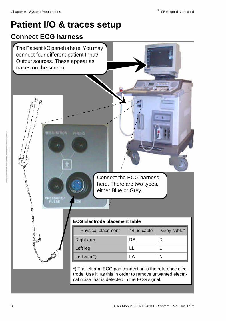
Patient I/O & traces setupConnect ECG harness
Connect the ECG harness here. There are two types, either Blue or Grey.
ECG Electrode placement table
*) The left arm ECG pad connection is the reference elec-trode. Use it as this in order to remove unwanted electri-cal noise that is detected in the ECG signal.
Physical placement “Blue cable” “Grey cable”
Right arm RA R
Left leg LL L
Left arm *) LA N
The Patient I/O panel is here. You may connect four different patient Input/Output sources. These appear as traces on the screen.

GE Vingmed Ultrasound Chapter A - System Preparations
User Manual - FA092423 L - System FiVe - sw. 1.9.x 9
Patient I/O & traces setup
Screen changes after ECG connectionIn 2D tissue mode, with no ECG trace, the screen may look like this.
HintIn Peripheral Vascular ac-quisition, the display of traces is off but may be re-configured to be on.
In Cardiac 2D Acquisi-tion, when ECG wiring is strapped to a patient and connected to the system, a trace from it appears as shown here.
WARNING!To obtain the correct isolation on the patient I/O only one connection (i.e.ECG, Phono, Pulse pressure or Respiration) must be used on the Scan-ner at a time.This means that in normal use the Scanner will have three open connectors. The System User must ensure that the patient cannot touch the open connectors.

Chapter A - System Preparations GE Vingmed Ultrasound
10 User Manual - FA092423 L - System FiVe - sw. 1.9.x
Patient I/O & traces setup
ECG trace control
The screen is redrawn, and some Trace controls are available on the Pad-dle-controlled menu.
HintScreen Functions are:- Timer Delay, Each step to the right lengthens time be-tween triggers, when on.- Keep Cont.frames,On/Off, for keeping the continually memory stored frames before switching to triggered scan or just over-writing the stored data.
At the re-program-mables on the con-trol panel these functions appear.
To access the Physio-logical trace controls, including ECG, press this key.

GE Vingmed Ultrasound Chapter A - System Preparations
User Manual - FA092423 L - System FiVe - sw. 1.9.x 11
Patient I/O & traces setup
ECG GAIN AdjustmentWhen the ECG trace ap-pears on the screen, it has a setting of maxi-mum gain and the wave-form height looks similar to this.
To reduce the waveform height, turn this rotary counterclockwise.
Reducing ECG GAIN also reduces the wave-form height shown.

Chapter A - System Preparations GE Vingmed Ultrasound
12 User Manual - FA092423 L - System FiVe - sw. 1.9.x
Patient I/O & traces setup
Set ECG trigger one In ECG Triggered acqui-sition, live scan data is synchronized with the heart cycle trace from the continually oncom-ing ECG data from the patient.
Through this you can relate seen heart abnor-mality occurrences to positions in time, along the heart cycle.
The systems dual ECG triggers allow you to pin-point events for Specific image display, each time you reach the pin-pointed section of the loop.
Press the ECG trigging key once and Turn ECGTrig1slightly clockwise. See the change at position ECG trig1 on the Trig-ging menu. See also the vertical trig marker and note that the shown screen scene will appear each time the screen update line passes the triggers.

GE Vingmed Ultrasound Chapter A - System Preparations
User Manual - FA092423 L - System FiVe - sw. 1.9.x 13
Patient I/O & traces setup
Set ECG trigger twoTo set a second trigger to capture for display another occurrence, rotate this rotary clock-wise. Notice the change in the below menu position ECG Trig2. See also the ECG trig2 marker and the image occurrence it represents.
Your acquisition is now ECG controlled. The first trigger updates your dis-played image 13 milliseconds after each R wave. The second trigger up-dates your image 33 milliseconds after each R wave.

Chapter A - System Preparations GE Vingmed Ultrasound
14 User Manual - FA092423 L - System FiVe - sw. 1.9.x
Patient I/O & traces setup
Timer Delay
Use this paddle to step the gray area on Timer Delay one step to the right.
The update will now skip every second R-wave Image update, as shown here.
Step the gray area an-other step. The update passes two R-waves be-fore image update shown here.
Use this paddle on the Traces menu to place the selection window onto Timer Delay.

GE Vingmed Ultrasound Chapter A - System Preparations
User Manual - FA092423 L - System FiVe - sw. 1.9.x 15
Patient I/O & traces setup
Timer Trigging
The Timer trigging markers appear as specified in Trace info window shown below.
To do Timer Trigging, press this key ON.
Rotate this rotary clock-wise to increase delay between image trig-gered updates shown here.

Chapter A - System Preparations GE Vingmed Ultrasound
16 User Manual - FA092423 L - System FiVe - sw. 1.9.x
Patient I/O & traces setup
Connect other trace sources
Press this key to se-lect a trace from a connected source for display on the image.
Besides the ECG source, connect a Heart microphone source, a Breath indicator source and one Pressure/Pulse device source at the other sockets.
Heart microphones, Breath indicators and Pressure/Pulse devices are available options from the manufacturer.
A Trace menu appears somewhere on the screen. Here, it appears in the Paddle (see below) con-trolled area.
Switches traces On-Off, sets gain levels and po-sitions traces on screen.
Moves select-win-dow Up and Down the Menu.

GE Vingmed Ultrasound Chapter A - System Preparations
User Manual - FA092423 L - System FiVe - sw. 1.9.x 17
Patient I/O & traces setup
Trace area size
With Large area chosen the Traces menu has these additional setting op-tions, the same as the Small Area.
To set or change the Trace area size on the screen, click ON/OFF Small, Mediur, Large or Full.
Using paddle controls, connect and switch ON Phono and Resp traces.
Adjust their settings, still using the Paddle controls, and the result will resemble the screen situation shown here.

Chapter A - System Preparations GE Vingmed Ultrasound
18 User Manual - FA092423 L - System FiVe - sw. 1.9.x
FootswitchMount the System Footswitch
To prepare it for use, pull it out of this open-ing and place it on the floor where you need it.
The system contains an internally connected Footswitch located in this slot.
WARNINGThe standard footswitch is not submersible. Do not use the standard foot-switch in operating rooms or other locations where fluids might be present on the floor. If you need a submersible footswitch in your environment, con-tact your local GEVU dis-tributor.

GE Vingmed Ultrasound Chapter A - System Preparations
User Manual - FA092423 L - System FiVe - sw. 1.9.x 19
Footswitch
Finding the Footswitch Mapping optionTo do Footswitch mapping, press this key to display the Setup menu.
IMPORTANTFootswitch mapping, as described here, will always relate to the presently active probe. When you save a Footswitch setup, it relates to this only. Other probes need new setup rounds.

Chapter A - System Preparations GE Vingmed Ultrasound
20 User Manual - FA092423 L - System FiVe - sw. 1.9.x
Footswitch
Footswitch Mapping
To REC/PAUSE tape recording, press and release this foot switch. Press and release it again to continue tape recording.
To FULL FREEZE the scan func-tion, press and release the center foot control. Press and release it once more to continue scanning.
Press and release the right hand foot control to IMAGE STORE from the Acquisition to the system Clipboard.
Using the Trackball, place the cur-sor within each switch menu and click select your switch setup shown above and described be-low.
Place the cursor onto Footswitch Mapping and press the Select ar-ea. To the right of the Setup menu the Foot-switch Mapping menu appears.

GE Vingmed Ultrasound Chapter A - System Preparations
User Manual - FA092423 L - System FiVe - sw. 1.9.x 21
Wheel lockingLock, Unlock scanner wheels
In upper position the rear wheels are direction locked but rotate freely
At the lowest position the system is parked and breaks are active on both-rear wheels.
At half way down position all wheels turn and rotate freely.

Chapter A - System Preparations GE Vingmed Ultrasound
A-22 User Manual - FA092423 L - System FiVe - sw. 1.9.x
External I/O PanelSystem I/O panel location
The External I/O connector panel is located here on the system.The panel sockets are identified on the next page.
WARNING
The External input and output sockets are not electrically isolated from the rest of the circuitry within System FiVe. Any instruments which are connect-ed to System FiVe via these inputs or outputs must conform to standard hospital electrical safety and leakage requirements. It is the responsibility of the user to ensure that this important safety requirement is met in all cas-es. When connecting the System FiVe to a non-isolated device, a Hospital grade isolation transformer should be used to supply the mains power.

GE Vingmed Ultrasound Chapter A - System Preparations
User Manual - FA092423 L - System FiVe - sw. 1.9.x A-23
External I/O Panel
Socket identifications
GR(aphic) RS232 and CPU RS232 sockets.
ETHERNET** socket. Used for communication with EchoPAC stand-alone.
SVHS OUT and SVHS IN sockets for Super VHS VCR connection.
COMP OUT and COMP IN connectors. COMP OUT is used by EchoPAC. COMP IN can be used by a great variety of sources, such as display of an X-Ray picture etc.
Four Analog input sockets. Can be used for auxiliary traces.
Output sockets for color printers.
ECG TRIG OUT socket.
**IMPORTANTConnect the Ethernet interface cable (FA200460) between the External I/O socket and the Ethernet adapter and slide latch these together. Arrange cabling to avoid any possible damages. When a patient is connected to the System, always use the Ethernet Isolation Box (P/N:EP200032, as shown to the right) to obtain correct isolation.

Chapter A - System Preparations GE Vingmed Ultrasound
24 User Manual - FA092423 L - System FiVe - sw. 1.9.x
Control Panel EquipmentHeadphone connection and volume adjustment
HELPINFO
TEXT PAGEERASE
LINEERASE
BODYMARK
ILLUM.
SCREENCONFIG
PHYS.TRACE
SPLITSCREENREC.
HEADPHONE
AUDIO
ACTIVEMODE
GAIN
2D
DEPTH
ZOOM
Connect the Headphone jack to this system socket and ad-just the sound level with the volume control above it.
The above volume control also regu-lates the sound level from the loud-speakers.

GE Vingmed Ultrasound Chapter A - System Preparations
User Manual - FA092423 L - System FiVe - sw. 1.9.x 25
Control Panel Equipment
Lamp Connection
HELPINFO
TEXT PAGEERASE
LINEERASE
BODYMARK
ILLUM.
SCREENCONFIG
PHYS.TRACE
SPLITSCREENREC.
HEADPHONE
AUDIO
ACTIVEMODE
GAIN
2D
DEPTH
ZOOM
Connect the plug end of the system lamp into this socket and adjust the emit-ted light level with the IL-LUM. Control directly below it.
HINTThe lamp is governed by a light sensor on the control panel. When it gets darker the lamp is lit. If an increase of emitted light from other sources prevail the lamp is switched off.

Chapter A - System Preparations GE Vingmed Ultrasound
26 User Manual - FA092423 L - System FiVe - sw. 1.9.x
Screen ConfigurationStart screen configurationTo select screen config-uration, press this key once.
This displays the options that are available for screen configuration on this dialog window.

GE Vingmed Ultrasound Chapter A - System Preparations
User Manual - FA092423 L - System FiVe - sw. 1.9.x 27
Screen Configurations
Configure Scanner Screen and VCR recording
Change image size here.
Displayduplex mode data Side By Side or Over/Under each.
Switch ON/OFF the display of KHz on a Doppler scale.
For description of Trace Sizes see page A-17.
Hide or Show scan pa-rameters on tape re-cordings.
Hide or Show Patient name on tape recordings.
To reserve the complete ultrasound area for trac-es, select Full.
To switch On/Off traces select this.
To choose a Small trace area select this one On.
Select a medium sized area with this one.
Select a large sized area with this one.
Hint!The Small trace area is default chosen at boot-up.
Chapter A - System Preparations GE Vingmed Ultrasound
28 User Manual - FA092423 L - System FiVe - sw. 1.9.x
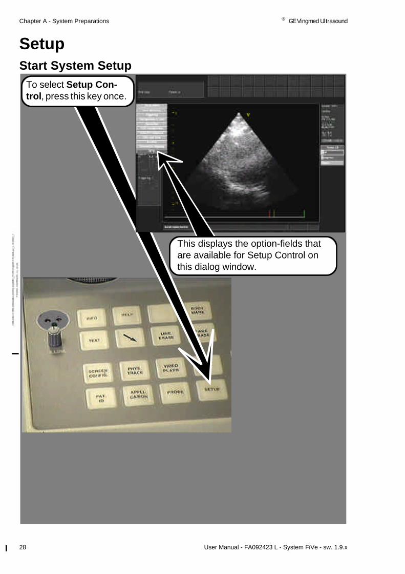
SetupStart System Setup
To select Setup Con-trol, press this key once.
This displays the option-fields that are available for Setup Control on this dialog window.

GE Vingmed Ultrasound Chapter A - System Preparations
User Manual - FA092423 L - System FiVe - sw. 1.9.x 29
Setup
Get a Setup Menu overview
Done exits you from the setup menu. Changes are automati-cally saved on exit by Done.
Here, you have an overview of the options on the Setup menu. Change the setup whenever you change probes or application.
Most of these options have their own separate descriptions on the following pages.
Footswitch mapping is described in the Foot-switch mounting description found on page 20.

Chapter A - System Preparations GE Vingmed Ultrasound
30 User Manual - FA092423 L - System FiVe - sw. 1.9.x
Setup
User Interface
Do your User Interface setups on this configura-tion screen. It allows you to configure Freeze and Autofreeze functionality.

GE Vingmed Ultrasound Chapter A - System Preparations
User Manual - FA092423 L - System FiVe - sw. 1.9.x 31
Setup
Do Date & Time and Location setupOn the Date and Time Setup dialog set the Date and time of day in a format that is select-able on the Location di-alog, described below.
To set date, make New Date area active, erase contents within, enter new date in same format as re-moved contents and click-select Set date to start it at Current Date.
To set time, make New Time area active, erase contents within, enter new date in same format as re-moved contents and click-select Set time to start it at Current Time.
On the Location Setup dialog, enter the Hospi-tal name. Enter the Hospital Department name where the system is to be used. Choose the native Language of the country that the hos-pital is located in and choose a Date and time format.To enter Hospital
and Department names, make each area active, erase any wrong contents, type the correct names at each.
To choose a Language or Date and Time For-mat for system display, place the cursor within each area and click-se-lect the correct lan-guage and Date and Time format.

Chapter A - System Preparations GE Vingmed Ultrasound
32 User Manual - FA092423 L - System FiVe - sw. 1.9.x
Setup
Do EchoPAC/Clipboard setup
Click-select here to dis-play the options for EchoPAC or Clipboard configuration.
The Image Store keys destination con-figuration area where you can set the button to do one of four dif-ferent storage meth-ods available within this area.
Set the time in-terval (ms) be-tween 2D frames when storing Doppler spec-trum or M-mode.
Here you can define what to store with the Image Store key.
Set Time span (ms) to transfer/store in live 2D-mode with-out ECG.
Set number of heartcycles to transfer/store, or Select single frame transfer/store.
To set the Image format for transfers to EchoPAC, select Preview cineloop before transfer, RGB trans-fer of single frame (image area) or RGB half resolution(full screen).
Insert the Trig point off-set in ms at this option to define where on the QRS the ECG trigger point is.

GE Vingmed Ultrasound Chapter A - System Preparations
User Manual - FA092423 L - System FiVe - sw. 1.9.x 33
Setup
VCR ConfigurationClick-select this option, and the VCR Configura-tion dialog appears.
Here, it is possible to make the Record/Pause key blink during recording or during a pause.
Here, you may enter a counter when the tape is inserted into the VCR recorder.
You can also click se-lect this key and set the counter value in this window.
When completed click OK, otherwise, click the Cancel function.
Here, you see a list of System FiVe support-ed VCRs.

Chapter A - System Preparations GE Vingmed Ultrasound
34 User Manual - FA092423 L - System FiVe - sw. 1.9.x
Setup
Configuration and Test
This is the Hardware Module overview. Ac-tives you module names, part numbers and their revisions levels, Master Control Document revision, Factory Order num-ber and production series number.
This function gives ac-cess to Password input for GE service and Sys-tem Options, tests, and Software and Hardware overviews.
The System options and password input example is displayed when you select Op-tions. Yellow text re-flects the installed, Black text displays the available.

GE Vingmed Ultrasound Chapter A - System Preparations
User Manual - FA092423 L - System FiVe - sw. 1.9.x 35
Setup
Diagnostic Tests, Software versions, GE Service
This is the password access to the system for GE Service personnel only.
Enter the password to gain access to this set of service functions
Select this key to start a Diagnostics test. The test proceeds auto-matically when you se-lect Run test. When completed, a list of re-sults is displayed in the grey area.
Select SW to display the system sw ver-sions.

Chapter A - System Preparations GE Vingmed Ultrasound
36 User Manual - FA092423 L - System FiVe - sw. 1.9.x
Setup
ECG Triggering
It allows you to set two individual ECG trigger intervals. Configure one of the pedals on the Footswitch to quickly toggle between the in-tervals.
To make the left ped-al toggle between the two, switch ON the ECG trig Interval sw.
In our example let’s enter 3 in the first input box and 5 in the next which means that we want the system to trigger at the third or fifth heartcycle.
Triggering is a special function for the Con-trast Option in ECG triggered acquisition.
The left switch pedal will now trigger at the third heart-cycle one time you press it and on the fifth the next time in accordance with our example.

GE Vingmed Ultrasound Chapter A - System Preparations
User Manual - FA092423 L - System FiVe - sw. 1.9.x 37
Internal Patient Archive*Open the internal Patient Archive
Hint You may scan a patient without entering Pa-tient ID. To store this however, in a retrievable manner, you should always do ID entries prior to storage. Scanning is described in Chapter B. Id entry and storage descriptions continue here.
To start the internal pa-tient archive for patient ID entries, press this key.
Internally, the system is designed to handle maximum 100 patients at a time. Within this lim-it, you can store externally, delete and add pa-tients as often as you wish. Internally Stored, Cine loops have typical data sizes ranging from 1MB to 5MB, because of probe and application choices for each. The patient archive, or individ-ual patients, can be transferred to an externally connected GE Vingmed Ultrasound EchoPAC Stand alone solution, along with measure-ments, cine loops etc. EchoPAC converts the incoming System FiVe data to its own format which allows you to use it at a later stage.
*The Internal Patient ar-chive is only available on Systems without an inte-grated EchoPAC.

Chapter A - System Preparations GE Vingmed Ultrasound
38 User Manual - FA092423 L - System FiVe - sw. 1.9.x
Internal Patient Archive
Do Patient information storage
The area for Patient ID entries where Minimum accepted input is the Last Name.
The area for examination background entries.
This is the Examinations overview area. Its displayed contents, also dependent on the input from the above areas.
Area for free text input as Referral reasons, Diagnosis and Comments.
Hints:Maximum number of char-acters in text entries:Last name: 30First name: 30
Birthdate: 10Patient ID: 30Street: 20Phone:20City:20
State: 20Weight:15height:15Zip:20
Hints:Max.Characters & entries:4 Pop-up menus: 8 user en-tries each.Operator:16
Resp Phys:16Rep Phys:16 Diag codes:16Echolab:20Tape:20
ExamID:20Counter:20
Screen function keys described separately on following pages.
INFOAll text input from keyboard. Delete text in-put with Backspace key.

GE Vingmed Ultrasound Chapter A - System Preparations
User Manual - FA092423 L - System FiVe - sw. 1.9.x 39
Internal Patient Archive
New Exam
Find patient
To tell the system that you are go-ing to do a New Examination, click-select this screen function.
Create New Examination
Use Undefined Patient
Create New Patient
Search For Patient
Use Current Patient
Cancel
On the New Exam menu that ap-pears, use the Trackball and the Select function to choose one of the menu alternatives or Cancel the activity.
To find a patient name stored on your system, click-select this func-tion.
Last Name First Name Examination
Hansen Hans
Images
01/11-1914 2 0
Wilson Will 24/06-1939 4 8
Cancel
On the patient list that appears, use the Trackball and Select function to choose the correct patient or cancel to exit.
A patient file similar to the one shown on the next page, regarding your selected patient, is displayed.
Note! If you are going to do a new examination, find the patient via the New Exam function.

Chapter A - System Preparations GE Vingmed Ultrasound
40 User Manual - FA092423 L - System FiVe - sw. 1.9.x
Internal Patient Archive
Complete an Exam entryA complete ID entry, pri-or to an exam, will re-semble this.
If EchoPAC is on-line with System FiVe, EchoPAC will also auto-matically create a home screen for your patient, shown to the left.
If you shut down Echo-PAC, and restart it, it au-tomatically comes up again with the same home screen.
Exit from patient ar-chive with Done or Cancel.
Minimum input is the last name.

GE Vingmed Ultrasound Chapter A - System Preparations
User Manual - FA092423 L - System FiVe - sw. 1.9.x 41
Internal Patient Archive
Do Ultrasound Image storageThe current patient file’s Ultrasound image area is here.
Hint!As mentioned previous you have an ultrasound data variation between 1MB and 5MB for a 1 second cineloop from live mode scanning. You can transfer cine loops to EchoPAC with related patient archive.
Hint!Stored images in frozen mode are approximately 50k as internally stored files.
You can store cine loops longer than one second and by that larger than five MB, but it will take a lot longer to store/recall such large cine loops.
Use this key to do Ultrasound data storage in frozen or live modes. The stored file is transferred to the system clipboard shown at the top of the il-lustration above and in the clipboard area of the illustration to the left.

Chapter A - System Preparations GE Vingmed Ultrasound
42 User Manual - FA092423 L - System FiVe - sw. 1.9.x
Internal Patient Archive
Cineloop AnalysisTo do Cineloop analysis on Patient archive stored images Click-select the image and this Analyze key.
Your one second cineloop appears here. See also the red and green cineloop end marks along the lower edge of the Ultrasound area. Set-up a cineloop or run through it with the trackball. Press the Pat ID key to return to the Patient archive.

GE Vingmed Ultrasound Chapter A - System Preparations
User Manual - FA092423 L - System FiVe - sw. 1.9.x 43
Internal Patient Archive
Add, Find, Edit, Delete Personnel…To do this select the Personnel… key at this location.
The Personnel…func-tion dialog window ap-pears. On it you can Find personnel, Delete personnel, Clear per-sonnel input from the personnel window, Can-cel personnel activity or just exit with Done.

Chapter A - System Preparations GE Vingmed Ultrasound
44 User Manual - FA092423 L - System FiVe - sw. 1.9.x
Internal Patient Archive
Patients list handling
To display the Archive Patients list click-Se-lect this key.
Exit from this with done.
Press this key to Save the current patient to the on-line EchoPAC solution. Images etc. are in the transfer.
To Select all in archive list, press this key.
Press this key to Delete a selection. It deletes your patient selection and its images etc.
The thirty patient files, are stored here when the scanner is not in any way connected to EchoPAC.
Use this function to handle patient file storage limits within the system (Thir-ty Patients). With it you can select the current, any individual or all files, transfer the current file, any file or all files to EchoPAC. After the transfer to EchoPAC, you can Delete current, any individual or all patient files, plus their images etc., from the internal storage area.
To Transfer all selected, or just a selected patient, to an on-line EchoPAC, press this key. Images etc., are in the transfer.
HintThe system can be con-figured so that all patient files established on the system go directly to EchoPAC storage and never land here.
Press this key to Save the current patient to the in-tern Disk
GE Vingmed Ultrasound Chapter A - System Preparations
User Manual - FA092423 L - System FiVe - sw. 1.9.x 45
Internal Patient Archive
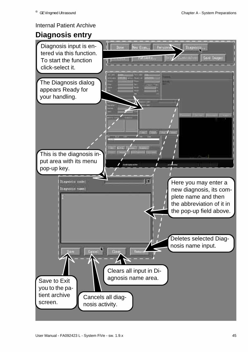
Diagnosis entryDiagnosis input is en-tered via this function. To start the function click-select it.
The Diagnosis dialog appears Ready for your handling.
This is the diagnosis in-put area with its menu pop-up key.
Here you may enter a new diagnosis, its com-plete name and then the abbreviation of it in the pop-up field above.
Clears all input in Di-agnosis name area.
Cancels all diag-nosis activity.
Save to Exit you to the pa-tient archive screen.
Deletes selected Diag-nosis name input.

Chapter A - System Preparations GE Vingmed Ultrasound
46 User Manual - FA092423 L - System FiVe - sw. 1.9.x
Image RecallRecall the clipboard image
To recall Clipboard stored images, press this key. You are then asked to click-select one of the icons on the clipboard area. Click-select it.
Your selected image recall is then dis-played as shown here.

GE Vingmed Ultrasound Chapter A - System Preparations
User Manual - FA092423 L - System FiVe - sw. 1.9.x 47
System Quick ReferenceSystem connections
3
4
6
7
Number label Title Contents
1 Headphone - Headphone connector with vol-ume control
2 Illum. - One lamp connector with Intensity adjustment
3 External I/O panel, (Left side, rear)See warning text on pageF-193
- Two RS232 interface sockets- One ECG TRIG socket- One Ethernet interface socket- One SVHS OUT socket- One SVHS IN socket- One Composite Video output
socket- One Composite video input socket- One B/W Video output socket- Four Analog input sockets- Output sockets for color printers
4 Patient I/O panel - One pressure sockets(option)- One Respiration socket(option)- One Phono socket(option)- One ECG socket
5 Rear wall - One mains cable- One Power ON/OFF switch- Protective earth
6 Upper Front End panel - Two Annular Phased Array probe sockets
- One Doppler probe socket- One system Standby-ON switch
7 Lower Front End panel - Sockets for three Phased Array probes
- A parking socket for an unused Phased Array probe
P.S.A Phased Array probes must be connected at position 1 before Power Up.
12
5
Warning:Even though they may look and feel alright afterwards, never continue using any Vingmed Probes that have been dropped onto or bashed against hard surfac-es . Such probes must be disconnected and tested by qualified personnel.
NoteStudy mobility warnings on pageF-193 before you start using the systems mobility.

Chapter A - System Preparations GE Vingmed Ultrasound
48 User Manual - FA092423 L - System FiVe - sw. 1.9.x
System Quick Reference
System communication
Number label Unit Communication type
1 Screen - Visual
2 Video Cassette Recorder - Taped
3 Loudspeakers - Sound
4 Control Panel - Key
5 Printer - Paper
6 Footswitch - Pedal switches
7 Printer - Paper
7
2
1
3
5
6
4

GE Vingmed Ultrasound Chapter A - System Preparations
User Manual - FA092423 L - System FiVe - sw. 1.9.x 49
System Quick Reference
Screen areas
Number label
Title Contents
1 Information display area - Patient ID- Clipboard- Current clinical application icon- Date and Time - Operator ID- Replay indicator- Thermal index - VCR Status- Active mode- Paddle report window- System messages- Warnings- User adjustable parameters- Performed measurements- Measurements list
2 Ultrasound display area
1
2
ClipboardPatientinfo
Scaninfo

Chapter A - System Preparations GE Vingmed Ultrasound
50 User Manual - FA092423 L - System FiVe - sw. 1.9.x
System Quick Reference
Scan mode selection
1 2 3
8 7
4
5
6
Number label Title Activity
1 ADD MODECURSOR/ - Adds a non-displayed mode to a Simplex mode or Duplex mode situation in combina-tion with the specific mode key
- Adds a screen cursor to desktop activities and displayed communication windows
2 DOPPL. - Starts the default Doppler Mode
3 M-MODE - Starts the M-Mode
4 CW|PW - Starts the CW and PW Doppler Modes
5 2D FREEZE - Halts activity in 2D mode
6 CFM - Adds Color Flow to 2D Mode and M-Mode
7 ACTIVE MODE - Switches active mode in Duplex and Triplex mode situations.
8 2D - Starts the 2D mode

GE Vingmed Ultrasound Chapter A - System Preparations
User Manual - FA092423 L - System FiVe - sw. 1.9.x 51
System Quick Reference
Basic mode adjustments
2 3
5
6
7
Number label Title Activity
1 TGC slides - Adjust the amount of echo brightness at specific depths in the 2D sector
2 GAIN, 2D - Adjusts the overall amount of echo bright-ness within the 2D sector
3 GAIN, ACTIVE MODE - Increases or decreases echo brightness within the active mode window
4 Assigned keys and rotaries - See next page.
5 ZOOM, Step variable. - Enables step variable zoom.
6 - Enables continuously variable zoom.
7 Depth, 2D sector - In 2D, 2D/color, M-Mode and Color M-Mode it adjusts the depth of the data sam-pling area which is displayed.
- In PW Doppler it adjusts the depth of the measuring point.
4
Continuously variable ZOOM
1

Chapter A - System Preparations GE Vingmed Ultrasound
52 User Manual - FA092423 L - System FiVe - sw. 1.9.x
System Quick Reference
Assigned Keys and Rotaries
Number label Title Contents
1 Upper assign panel - A continually mode updated rotary func-tion label window
- A row of mode assigned rotaries
2 Lower assign panel - A continually mode updated key function label window
- Mode assigned keys
1
2

GE Vingmed Ultrasound Chapter A - System Preparations
User Manual - FA092423 L - System FiVe - sw. 1.9.x 53
System Quick Reference
System screen tools
Number label Title Activity
1 SPLIT SCREEN - Divides the acquisition area into two halves, horizontally or vertically.
2 SELECT SCREEN - selects active screen
3 Select key - confirms selections
4 Trackball - steers the Pointing device
5 Vertical paddle switch - moves activity between menu fields vertically.
6 Horizontal Paddle switch - moves activity between menu fields horizon-tally.
2 5 61 3 4

Chapter A - System Preparations GE Vingmed Ultrasound
54 User Manual - FA092423 L - System FiVe - sw. 1.9.x
System Quick Reference
Post-processing functions1 2 3 4
6
7
8
9
10
11
15 14 13 1216
Number label Title Activity
1 TEXT - starts the text annotations function.
2 ARROW - allows arrow annotation with trackball and select key.
3 LINE ERASE - removes a selected text line.
4 BODY MARK - starts body marking function.
5 PAGE ERASE - erases all annotation arrows on active screen.
6 REPORT - starts the report generator function.
7 IMAGE RECALL - recalls stored image from clipboard.
8 VIDEO PREVIEW - displays video preview before VCR storage.
9 REC/PAUSE - remote VCR control.
10 PRINT (ALT.) - prints on alternative printer.
11 PRINT - prints on default printer.
12 MEAS. - starts M&A.
13 IMAGE SIZE -changes size of displayed image .
14 FULL FREEZE - halts active scanning
15 IMAGE STORE - saves single images or cineloops to clipboard.
16 CALIPERS - starts calipers M&A
5

Chapter B
Scanning
This section tells you about:
• 2D Mode . . . . . . . . . . . . . . . . . . . . . . . . . . . . . . . . . . . . . . . . . . . . . . . 56
• Depth Control . . . . . . . . . . . . . . . . . . . . . . . . . . . . . . . . . . . . . . . . . . . 64
• GAIN . . . . . . . . . . . . . . . . . . . . . . . . . . . . . . . . . . . . . . . . . . . . . . . . . . 65
• Acquisition mode handling . . . . . . . . . . . . . . . . . . . . . . . . . . . . . . . . . 67
• Memory Replay . . . . . . . . . . . . . . . . . . . . . . . . . . . . . . . . . . . . . . . . . . 69
• Annotations . . . . . . . . . . . . . . . . . . . . . . . . . . . . . . . . . . . . . . . . . . . . . 70
• Body Marks . . . . . . . . . . . . . . . . . . . . . . . . . . . . . . . . . . . . . . . . . . . . . 76
• Color Flow Mapping . . . . . . . . . . . . . . . . . . . . . . . . . . . . . . . . . . . . . . 81
• Traditional M-Mode . . . . . . . . . . . . . . . . . . . . . . . . . . . . . . . . . . . . . . . 97
• Anatomic M-Mode . . . . . . . . . . . . . . . . . . . . . . . . . . . . . . . . . . . . . . . . 100
• Color M-Mode . . . . . . . . . . . . . . . . . . . . . . . . . . . . . . . . . . . . . . . . . . . 104
• Side by side viewing . . . . . . . . . . . . . . . . . . . . . . . . . . . . . . . . . . . . . . 107
• Doppler . . . . . . . . . . . . . . . . . . . . . . . . . . . . . . . . . . . . . . . . . . . . . . . . 108
• Tape Recording . . . . . . . . . . . . . . . . . . . . . . . . . . . . . . . . . . . . . . . . . . 116

Chapter B -Scanning GE Vingmed Ultrasound
56 User Manual - FA092423 L - System FiVe - sw. 1.9.x
2D ModeStart 2D scanning
Place the probe onto the patient, start scan-ning and image adjust-ment.
At every boot-up, the System Five starts in the previous shut-down mode.Here, It is 2D-Mode.
In this case the patient is also connected with ECG cabling where trace handling etc., is described in chapter A, under section for Patient I/O & traces setup.
About 2D Mode -12d mode gives a 2-Di-mensional ultrasound-generated view of the heart where you perfect its presentation with mode - available tools.
About 2D mode - 2The gotten views allow you to study tissue be-havior and valve functioning primarily.

GE Vingmed Ultrasound Chapter B -Scanning
User Manual - FA092423 L - System FiVe - sw. 1.9.x 57
2D Mode
Ultrasound picture Controls
To the left here we have two screen paddle menu sets of 2D cardiac picture controls. The farthest away one is at FULL FREEZE and the nearest in live mode. None of these control positions are permanent.
Tilt
DDP
Compress
Reject
Dynamic Range
Contour
Diff off/on
Power
Tissue 2D
In 2d cardiac you may have screen controls situated shown on this page. Which controls are present and set-tings et cetera are de-finitively probe and application selection dependable.
The upper set of key-board controls (4 ON/OFF switches and 4 Rotaries) are here available in live scan-ning. The Lower set (2 ON/OFF switches) is available at FULL FREEZE.

Chapter B -Scanning GE Vingmed Ultrasound
58 User Manual - FA092423 L - System FiVe - sw. 1.9.x
2D Mode
Control Panel Re-programmable Rotaries & keysAngleControls the scan sector angle.
FramerateFramerate controls the resolution in im-age movement and detail. Increase the framerate to get frames with less focal points and made up of wider beams, which in turn gives images with poor detail resolution but high temporal resolution.A framerate reduction does the exact op-posite.The control is not available for APAT(annular array) probes.
Up/DownTheseflip the ultrasound image upside down or downside up.
Left/Right These flip the ultrasound Image right or left
B-Mode maps (Live and FREEZE)This function Displays a menu of alterna-tive color maps for displayed tissue, se-lectable from the trackball and Select key area.
Cineloop (FULL FREEZE only)is a group of functions that you to create and run a mini movie from the stack of scan data found in the systems replay memory.
FocusFocus positions the transmit focus point(s) within the transmitted sector depth, indicat-ed by a focal marker on the screen depth scale. Available focal regions overlap, and make it possible to focus on any part of the image.If you use ZOOM in live 2D, the focal point(s) move to within the zoomed part of the image. If you exit from zooming, with-out touching the focal control, the focus re-turns to the position it had before you activated ZOOM.
FrequencyFrequency is the transmitted frequency that your acquisition scan has. Frequen-cy variations, depends on probe and ap-plication selections. -Increase the frequency value to im-prove resolution.
-Reduce thefrequency value to improve penetration.
There is often a tradeoff situation be-tween the two.Frequency adjustment in 2D imaging changes the display framerate and moves the focal marker to a new posi-tion on the screen depth scale.
The Cineloop Re-pro-grammables

GE Vingmed Ultrasound Chapter B -Scanning
User Manual - FA092423 L - System FiVe - sw. 1.9.x 59
2D Mode
Screen commands, Cardiac, Live & Full freezeDDP (Data Dependent Pro-cessing)In cases where normal scan ad-justments are not enough, cases where random artifacts, appear as bright speckles, in your image, try DDP. Increase DDP to remove the speckle without effecting moving structures such as valve flaps etc.
CompressCompress adjusts the greyscale range of your image. No Compress hardens your image, giving it a black and white appearance. In-creased Compress tends to make your image grayish, and in turn softer.
RejectReject removes low amplitude unwanted noise echoes in your image. Increased Reject darkens your image and re-moves more and more of the low amplitude echoes. Avoid removing relevant low amplitude echoes. After Compress & Reject, readjust Gain, if necessary.
L
RDU
Menu
Value
Tilt
DDP
Compress
Reject
Dynamic Range
Contour
Diff off/on
Power
Tissue 2D

Chapter B -Scanning GE Vingmed Ultrasound
60 User Manual - FA092423 L - System FiVe - sw. 1.9.x
2D Mode
Screen commands, Cardiac, live only
PowerPower adjusts penetration effectiveness. It does not increase the background noise that makes unwanted artifacts in doing so. Power increase improves penetration.
Diff OFF/ONThis affects reverberations in the image. If turned on the frame rate (or focal zones) will decrease, while the reverberations at-tenuate
Dynamic rangeThis function gives shades of gray to the various intensities of the incoming image data. It differs from Compress, Reject, postprocessing or screen adjustment controls because it actu-ally preprocesses the grayscale range of the incoming data. Dynamic Range is a live mode function which is unavailable in Full Freeze mode.
ContourContour adjusts the edges enhancement in an image. Adjust-ments towards minimum give minimum enhancement.
Tilt
DDP
Compress
Reject
Dynamic Range
Contour
Diff off/on
Power
Tissue 2D

GE Vingmed Ultrasound Chapter B -Scanning
User Manual - FA092423 L - System FiVe - sw. 1.9.x 61
2D Mode
Sector Tilt
Tilt
DDP
Compress
RejectDynamic Range
Contour
Diff off/on
Power
Tissue 2D
L
RDU
Menu
Value
Tilt is active, whenever there is a 2D image present on the screen, without a Time motion cursor. When the cursor is displayed, tilt adjust-ment is disabled.
On this System a less than 90°sector is tiltable in any direction, left and right, within the probes 90° scan range, by merely stepping the paddle.
The Yellow marker that is visible at the top of the sector, marks the probe diode light’s position.

Chapter B -Scanning GE Vingmed Ultrasound
62 User Manual - FA092423 L - System FiVe - sw. 1.9.x
2D-Mode
Octave Tissue ImagingStandard B-mode (2D) imaging transmits and receives ultrasound at roughly the same fre-quency. At higher power levels, return echoes from tissue are generated not only at the original frequency but also at twice the frequency transmitted. This frequency, known as the second harmonic, is one octave higher than the original frequency. These echoes are mixed with normal echoes when they return to the transducere but are much weaker. With-in the System Five the second harmonic, from the received spectrum is separated, am-plified and processed for display.
To start Octave Tissue Imaging that is avail-able with 2.5 and 3.5MHz FPA, 3.25MHZ Apa and 3.5MHz CLA probes, adjust the Freq rotary to the active probe’s two lowest fre-quency levels.
Notice the displayed frequency reading.
A Text, confirming that you are in Octave, ap-pears in this information window when it is active.
Shortly after the dis-played image from Oc-tave Tissue Imaging appears.

GE Vingmed Ultrasound Chapter B -Scanning
User Manual - FA092423 L - System FiVe - sw. 1.9.x 63
2D-Mode
How does Octave Imaging improve image quality?When Octave Imaging is active, the transmitted frequency is lowered, fully utilizing the high bandwidth of the transducer. At lower frequency the ultrasound beam becomes less sensi-tive to the non-linear characteristics of tissue; it also penetrates further into the tissue before losing signal strength.Thus with lower transmit frequency more signal energy reaches the region of interest.
The harmonic ultrasound signal is then reflected from the organ and back to the transducer, just like the original(fundamental frequency) ultrasound signal. Very little harmonic signal is generated from “noise echoes” often seen in the blood pools and as general noise; therefore the returned signal provides better contrast separation betweentissue and blood pools. Since the frequency is doubled,Octave Tissue Imaging also provides twice the lateral reso-lution due to the increased effective aperture.

Chapter B -Scanning GE Vingmed Ultrasound
64 User Manual - FA092423 L - System FiVe - sw. 1.9.x
Depth ControlAdjust Region of Interest DEPTH
2D Depth moves your scanned Region of In-terest, up or down, with-in the viewed sector.
It also redraws and reduces Depth reading here.
MoveROIUPMove
ROIDown
An example of depth movement could look like this. The Region is now at a lower position on the screen.

GE Vingmed Ultrasound Chapter B -Scanning
User Manual - FA092423 L - System FiVe - sw. 1.9.x 65
GAINGain Location
To adjust the amplifica-tion of all received sig-nals we have the Gain center on the Control panel. From it, you may add and reduce the am-plification over all, in the active mode and at spe-cific depths of received scan data to improve the detail visibility on the screen.

Chapter B -Scanning GE Vingmed Ultrasound
66 User Manual - FA092423 L - System FiVe - sw. 1.9.x
Gain
Adjust Gains
2D Gain adjust the amplifica-tion of tissue in tissue in the displayed 2D sector.
TGC has eight slide-potentiome-ters. Each of these allow you to separately adjust the amplification of displayed data at eight specific depths on the displayed 2D sector. The mid-positioning of all, shown here should give correct TGC for the normal patient.
Active Mode Gain ad-justs, as it states, Gain in the mode that is active. In 2D mode it does the same as the 2D gain rotary. In color flow it adjusts the color flow etc.
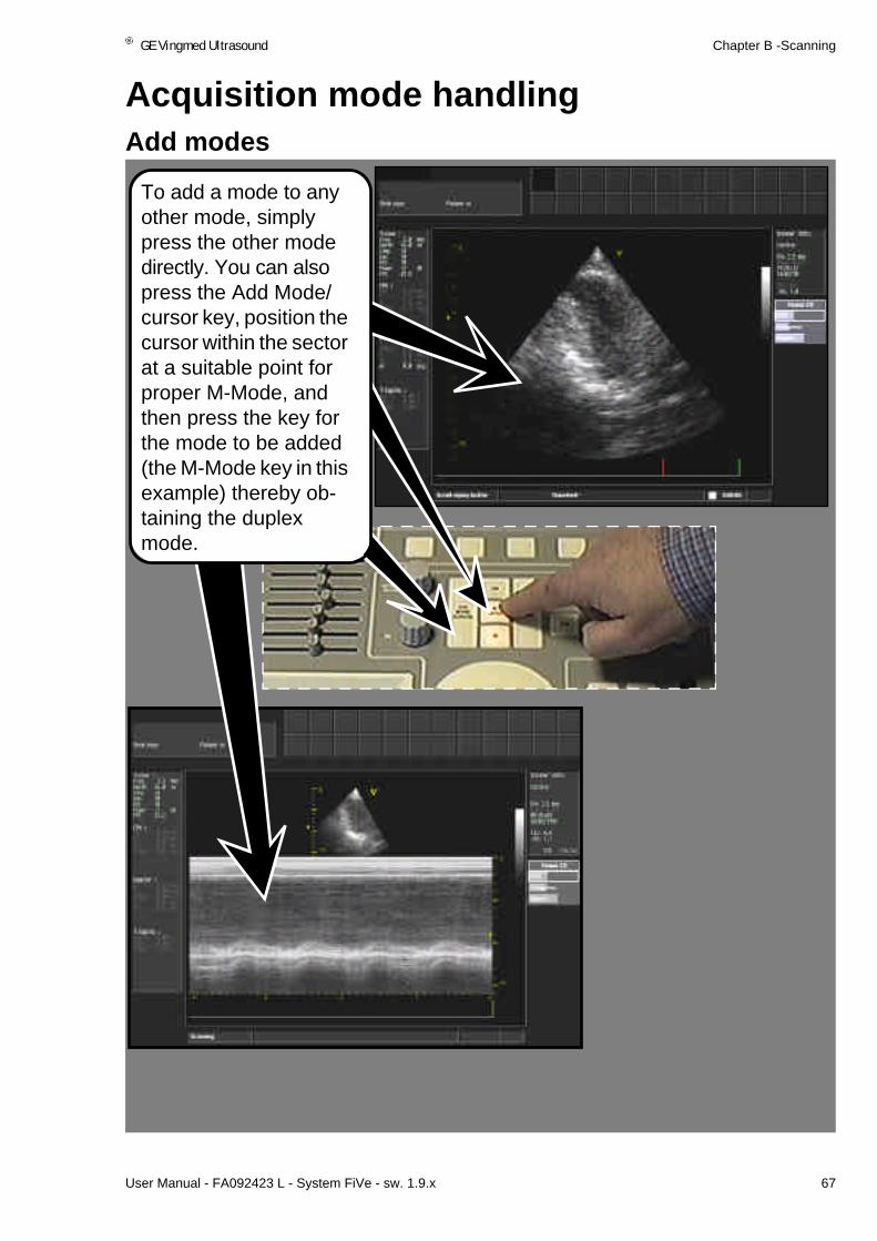
GE Vingmed Ultrasound Chapter B -Scanning
User Manual - FA092423 L - System FiVe - sw. 1.9.x 67
Acquisition mode handlingAdd modes
To add a mode to any other mode, simply press the other mode directly. You can also press the Add Mode/cursor key, position the cursor within the sector at a suitable point for proper M-Mode, and then press the key for the mode to be added (the M-Mode key in this example) thereby ob-taining the duplex mode.

Chapter B -Scanning GE Vingmed Ultrasound
68 User Manual - FA092423 L - System FiVe - sw. 1.9.x
Acquisition mode handling
Use the Active Mode key to change ParametersTo display tissue adjust-ment parameters when in 2D/Color Flow, with Color Flow adjustment parameters present, press the Active mode key once the Color flow key starts to blink. Be-fore it stops blinking press the 2D key once.
The parameters appear here.
The 2D tissue parameters are also available on the pro-grammable rotaries as you can see in our example where we have adjusted the Angle Rotary.

GE Vingmed Ultrasound Chapter B -Scanning
User Manual - FA092423 L - System FiVe - sw. 1.9.x 69
Memory ReplayReplay memory handling
To do memory replay, press FULL FREEZE at a stage of interest in your acquisition, and your system memory now filled with prelimi-nary stored ultrasound data.
So, as the system prompts you to do, scroll the Replay buffer with the trackball.
Total number of frames.
Current frame.
Number of seconds from start of memory

Chapter B -Scanning GE Vingmed Ultrasound
70 User Manual - FA092423 L - System FiVe - sw. 1.9.x
AnnotationsStart Annotation
The light in the key lights up and the Annotations menu appears at this lo-cation on the screen.
To start Annotations on a displayed image, select this key on the control panel.
Hint When you select the TEXT key, you can start typing a text on the keyboard that will appear on the sector without having done anything on the Annota-tions menu to begin with.

GE Vingmed Ultrasound Chapter B -Scanning
User Manual - FA092423 L - System FiVe - sw. 1.9.x 71
Annotations
Add a menu Arrow
Move the trackball again and now the ar-row shaft stretches, or crimps or the whole ar-row and shaft rotate around the anchor.
Using this knowledge, maneuver the shaft and arrowhead so that it points at its target and press select to anchor it completely.
An arrowhead appears on the screen. Using the trackball, maneuver it onto the location you want to anchor its shaft at and press the select key.
To add a menu arrow select this menu posi-tion.
A quite different arrow pointer key is also available on the control panel. When selected its key lights up and the arrow pointer pops onto the screen. It is also maneuvered, positioned as if fastened to the trackball and select key.

Chapter B -Scanning GE Vingmed Ultrasound
72 User Manual - FA092423 L - System FiVe - sw. 1.9.x
Annotations
Enter an menu text abbreviation
Highlight and choose AO with the Select key, and your input appears with a text input cursor behind it. If necessary, you can edit or add text from system keyboard.
To anchor it at this loca-tion, press the select key. Use Line Erase to delete the selected in-put.
Maneuver the input to its planned position with the trackball.
Use Edit to change a text input or to move it to another location.

GE Vingmed Ultrasound Chapter B -Scanning
User Manual - FA092423 L - System FiVe - sw. 1.9.x 73
Annotations
Change a text entryTo Change a text entry, choose Edit on the menu, place the Cross cursor that appears on the screen, onto AO, and press Select. A short and vertical line cursor, replaces the cross, and places itself behind the AO text. Press the Backspace key once, and O disap-pears.
You can also use the LINE ERASE, and the PAGE ERASE keys to erase single entries, one by one, or all en-tries in one selection.

Chapter B -Scanning GE Vingmed Ultrasound
74 User Manual - FA092423 L - System FiVe - sw. 1.9.x
Annotations
Configuration
To do Annotations con-figuration click select this position on the An-notations menu. A con-figuration dialog appears.
Move Up or Move Down highlighted text. Delete highlight-ed text.
Add new text en-try input from keyboard in this area.
Cancel all con-figuration activi-ties.
Save all changes, deletions, additions et cet-era, and even establish a new menu position if necessary after changes.
Factory

GE Vingmed Ultrasound Chapter B -Scanning
User Manual - FA092423 L - System FiVe - sw. 1.9.x 75
Annotations
Setup
Do Annotations setup as clearly explained on this dialog.
To do Annotation settings select the function here.

Chapter B -Scanning GE Vingmed Ultrasound
76 User Manual - FA092423 L - System FiVe - sw. 1.9.x
Body MarksStart the Body mark function
To add BODY MARKS to your displayed ultra-sound picture, press this key on the control panel.
Body marks appear on the Annotations menu.The body mark selection that appears is applica-tion-dependent. These are the Carotid applica-tion ones. See Body marks for other application below. They function as described here.
Aorta IIiac
Abdo,PedAbdo and Renal.
Pelvic and Gyn.
LegArt and LegVein
Small Parts
Page Erase removes all Body marks and Anno-tation inputs. Line Erase takes the click-se-lected ones only.

GE Vingmed Ultrasound Chapter B -Scanning
User Manual - FA092423 L - System FiVe - sw. 1.9.x 77
Body Mark
Select a body mark Whenever you need to add a body mark during ultra-sound scanning start the body marking function, de-cide which mark view suits your needs and click select it shown below.
The Annotations menu always ap-pears in a ready for editing status.
By default setup, the selected Body mark pops onto your ultrasound situation, shown here.The Probe Indicator is active and locked to all Trackball movement, ready to be moved around the Body mark.
Key operators are:Del to go Backwards one step, at each entry, to previous activity.Select to go forward one step to next activity.

Chapter B -Scanning GE Vingmed Ultrasound
78 User Manual - FA092423 L - System FiVe - sw. 1.9.x
Body Mark
Move the Body mark and Probe Indicator
Use the Trackball, move the Body Mark to a desired position on the ultrasound sector and press Select to lock it there.
To move the Body mark around your ultrasound situation, press the Del key and the Body Mark is now locked to all trackball move-ment.
The Select input also exits you from Body mark movement to Probe Indicator movement.
The Del key input exits you from Probe Indicator movement to Body mark movement.
The Select key input also exits you to the next activity which is Turn or Ro-tate the Probe indicator at the locked position. For more on this see the next page.
A Del key input returns you to Move Body mark mode, if you need to ad-just it.
To move the Probe indicator on the Body mark, roll the Trackball in the desired direction. When satisfactory, press Select to lock it at the position.

GE Vingmed Ultrasound Chapter B -Scanning
User Manual - FA092423 L - System FiVe - sw. 1.9.x 79
Body Mark
Turn or Rotate Probe IndicatorThe Indicator’s short and right-angled line is the probe head. The rest of it is the probe body. Trackball rota-tion rotates the body around the locked in place head.
At the new angle, press the Select key once to lock it at this position.
A Del input returns you to the previous situation where you can move the Probe Indicator on the Body mark.
Select also exits you to the next activity.
Roll the Trackball to the left or right and the Probe Indicator turns or rotates leftward or rightward.

Chapter B -Scanning GE Vingmed Ultrasound
80 User Manual - FA092423 L - System FiVe - sw. 1.9.x
CompoundStart Compound
Some probes for System five have the Compound function.
Select the Compound function here.
Traditional PV scanning will normally give you a screened image situation similar to this.
When activated Com-pound gives you a screen situation that re-sembles this. You should clearly see that the area within the yel-low rectangle is much clearer than in the im-age above.
The reason for this is that with Compound one scan is “shot” with-in the dot- rimmed area and the next one within the Line-rimmed area. This gives the Yellow marked area double coverage which results in a better picture.

GE Vingmed Ultrasound Chapter B -Scanning
User Manual - FA092423 L - System FiVe - sw. 1.9.x 81
Color Flow MappingStart Color Flow in 2D mode
To start Color Flow in 2D mode, press this key directly or go via the Add Mode/Cursor key. Two clearly seen lines appear on the 2D sec-tor that mark the color limits.
As you scan in live mode you will see col-or flow appear within this sector. You may need to adjust the Ac-tive Mode gain rotary.
Note that the term Color Flow is a generic term which includes the three Color Flow modes that are available in the system:
* Conventional Color Flow Mapping* Power Amplitude Doppler (Ref: page 96.)* Tissue Velocity Imaging (optional).See separate Manual.Conventional Color Flow Mapping provides information (bandwidth and direction) about the velocity, bandwidth and direction of blood flowing in the Region of Interest box. Blood flowing towards the transducer is mapped in red, while blood flowing away from the transducer is mapped in blue. Blood flow that contains a variety of velocities which often appear where there is turbulence or a jet mapped in green.Tissue Velocity Imaging maps velocities from tissue motion to colors in accordance with a color map.

Chapter B -Scanning GE Vingmed Ultrasound
82 User Manual - FA092423 L - System FiVe - sw. 1.9.x
Color Flow Mapping
Move the color sector within the 2D sectorIn live scanning, right and left Trackball move-ment moves the color sector simultaneously. You may also want to change color maps and this is done at the as-signable keys on the control panel.

GE Vingmed Ultrasound Chapter B -Scanning
User Manual - FA092423 L - System FiVe - sw. 1.9.x 83
Color Flow Mapping
Programmable Keys and Rotaries
Here are the re-pro-grammable keys and Rotaries in live color flow.
The same in FULL FREEZE.
Low Velocity Reject re-moves all low velocity signals below certain predefined levels. These are normally coming from low veloci-ty blood flow and tissue movement noise.The rotary has two steps, or levels. Find the current level at this position on the Tissue/Color Flow Mapping settings infor-mation window.
WARNINGFrequency adjustment In Doppler or Color Flow modes affects the maximum size of the available velocity range. (Frequency increase lowers the maximum).

Chapter B -Scanning GE Vingmed Ultrasound
84 User Manual - FA092423 L - System FiVe - sw. 1.9.x
Color Flow Mapping
Color map selection
To change color maps press the below shown programmable key marked COLOR MAPS.
On the Color Menu use the trackball and select area key to choose your map selection.

GE Vingmed Ultrasound Chapter B -Scanning
User Manual - FA092423 L - System FiVe - sw. 1.9.x 85
Color Flow Mapping
Invert color mapTo Invert your color map, press this key.
The inverted map ap-pears here.

Chapter B -Scanning GE Vingmed Ultrasound
86 User Manual - FA092423 L - System FiVe - sw. 1.9.x
Color Flow Mapping
Region of interest handling
Adjust ROI Span shown above to achieve situations to the right and adjust ROI Width shown below to the Right, to achieve situations shown direct below. Trackball ad-justs the angle of ROI.

GE Vingmed Ultrasound Chapter B -Scanning
User Manual - FA092423 L - System FiVe - sw. 1.9.x 87
Color Flow Mapping
Tissue priorityWhile you are scanning or in FULL FREEZE Move onto Tissue Prior-ity on the paddle menu and pace it at a mini-mum value with the right/left paddle. The color on your image has now the priority shown to the right. You may here have tissue detail that is not visible be-cause of flow. Continue with the investigation shown below.
Using the same paddle and in live or frozen sta-tus and adjust Tissue priority to the approxi-mately same level shown to the left. Color is hardly visible, and tis-sue has the priority. It is now possible to view structures that were not visible when color had the priority.
HintThe paddles govern the right hand menu as described earlier.

Chapter B -Scanning GE Vingmed Ultrasound
88 User Manual - FA092423 L - System FiVe - sw. 1.9.x
Color Flow Mapping
BaselineIn color flow, find Base-line on the re-program-mable rotaries shown below and on the pad-dle menu. It allows you to view suspecting flow velocities shown in ex-amples to the right and below.
Above we adjust Baseline to a mini-mum, to study the negative velocities. Notice the color bar.To the left we adjust Baseline towards maximum to look at positive velocities. Notice also the color bar change and vari-ance is present in both.

GE Vingmed Ultrasound Chapter B -Scanning
User Manual - FA092423 L - System FiVe - sw. 1.9.x 89
Color Flow Mapping
Variance
At a minimum setting or, when switched off at the re-programma-bles the Variance func-tion is not present on the color bar or in the displayed flow of the right hand view.
Whereas when you paddle onto or switch On Variance it is present on the image and in the color bar.
About Variance - 1
Variance selection, is avail-able in both live scanning and full freeze
Variance is a measure of how disturbed, or non-luminary the flow is at the given sam-ple volume. From a technical point of view, it is the band-width of the velocity informa-tion.
About Variance - 2Use Variance maps when you look at disturbed flows. Such flows include jets of all sorts, regurgitations, leaks, ASDs, VSDs and the like.Intensity is a measure of the amplitude of the echoes coming back from the sam-ple volume. Intensity maps are best suited when you are looking at slower flows, ven-tricle filling, Carotids etc.

Chapter B -Scanning GE Vingmed Ultrasound
90 User Manual - FA092423 L - System FiVe - sw. 1.9.x
Color Flow Mapping
How Color Flow Mapping works
Understanding the basic processes for Color Flow images is how to get the best color flow images possible from striking the optimal balance between frame rate, mapping angle, quality (“packet size”) and Low Velocity Reject.
This section will establish a basic understanding of what color flow mapping is, and briefly describe the complex series of events that must happen to build a color flow map in real time.
In Doppler Spectrum Analysis (pulsed) a large mathematically transformed data set from a given sample volume is to yield the spectrum of velocities present in that sample volume over the time. Because the interrogation of one specific sample volume at a time is typical, there is a continuous stream of data available from that location, and time or frame rate is not a factor.
In Color Flow Mapping, a limited set of data from a given sample volume is collected over an interval of time which is as short as possible. Mathematically manipulated data produce the Color Flow outputs for this sample volume. The outputs obtained are an estimate of the mean velocity, the intensity or power of the signal, and a measure of the statistical variance of the velocities in the sample.

GE Vingmed Ultrasound Chapter B -Scanning
User Manual - FA092423 L - System FiVe - sw. 1.9.x 91
Color Flow Mapping
Color Map construction
A color flow map construction enhanced from an array of a variable amount of indepen-dent color flow lines, each of which is taken from a variable amount of independent sam-ple volumes, obtained as described on the previous page. Although all the sample volumes on a given flow line are evaluated and obtained simultaneously, each line re-quires many ultrasound pulses to make velocity estimates.
The flow information from the array of lines combined with 2D information, collected on an independent 2D scan, to yield the whole color flow map. At each location in the dis-played sector you have either an echo intensity or a mean velocity.Constructing a color flow image, therefore, can take a considerable length of time.
The key to understanding the velocities being mapped is understanding the color bar. This is a pictorial trans-lation table that will allow you to associate a color on the flow map with a particular flow state. To understand what the color bar represents, one must first under-stand what information is available from the color flow mapping process.

Chapter B -Scanning GE Vingmed Ultrasound
92 User Manual - FA092423 L - System FiVe - sw. 1.9.x
Color Flow Mapping
The Spectral Estimate
Spectral estimation is the process in which the CFM extracts velocity information from the returning Doppler shifted ultrasound data. Thethree parameters, mean velocity, sig-nal intensity, and the variance of velocity determines each pixel on the flow map, i.e., each range gate along each flow vector. The mean velocity is the statistically deter-mined average velocity. Variance is a measure of the bandwidth of the velocity spec-trum. It tells how much the velocity typically deviates from the average velocity. The intensity is a measure of the returning signal strength.
Spectral estimation depends on a mathematical process called auto-correlation to con-vert the Doppler shifted echoes into velocity information. The raw outputs of the auto-correlation process are a set of rays, each having an angle and a length. The angle of the ray corresponds to the velocity, and can range from O to 1 Nyquist Velocity covering the span of O to 180°. The length of the ray is proportional to the signal intensity.
Spectral estimate rays can be drawn on the wheel shown here. On this wheel one ray is drawn, although for the spectral estimate there will be at least three (Application de-pendent) generated in the Color Flow Mode. One thing to notice is that for any given ray there is no way to deduce whether the velocity detected is flowing to or from the trans-ducer. Inference from observed hemodynamics, determine the flow direction in clinical situations.
Zerovelocity
Nyquistvelocity
Increasing “red” velocities
Increasing “blue” velocities

GE Vingmed Ultrasound Chapter B -Scanning
User Manual - FA092423 L - System FiVe - sw. 1.9.x 93
Color Flow Mapping
Assigning Colors and unwrapping the Color Wheel
Although the flow wheel represents a continuous process, in color flow mapping systems the wheel is always “cut” at some point to be unwrapped and displayed on the monitor. The exact cut location on the wheel is arbitrary. The cut location is similar to the position of the baseline in a Doppler spectrum display.
Locations on the wheel shown on the previous page have assigned colors in red/blue flow maps. This type of color assignment is the core of most manufacturer’s red/blue maps. In the Vingmed map, intensity is an additional factor. This will appear on the color wheel as concentric rings, growing brighter as the diameter grows. Adding intensity to the color assignments helps to give the mapped velocities a more flow-like appearance.

Chapter B -Scanning GE Vingmed Ultrasound
94 User Manual - FA092423 L - System FiVe - sw. 1.9.x
Color Flow Mapping
Disturbed Flow Indicator
The Disturbed Flow Indicators purpose is to help in the visualization and delineation of turbulent flows and jets. A set of color maps is available for selection on the Color Map menu. In cardiac Yellow/Cyan is the normally used map. Disturbed Flow describes a variety of flow conditions that are not well defined by a flow map that incorporates only the velocity and in-tensity parameters into the color assignment pro-cess.
The turbulence causes the presence of a broad range of velocities so that the mean velocity statistic is not very significant. This is the classic example of Disturbed Flow. The variance display allows you to see variation from normal velocities or turbulent flow. This type of turbulent flow ids associated with dop-pler data with a broad bandwidth such as signals generated by valvular regurgitation, valvular stenos-is and intercavity shunts.
With the Disturbed Flow Indicator system, when the system determines that the given combination of in-tensity, mean velocity and variance will not yield meaningful mean velocity data, a shade of green substitution, not addition, forthe mean velocity color. These green areas stand out from the other flow ar-eas, and catch the eye’s attention as often brief phe-nomena pass by. The heart of the Disturbed Flow system is Deciding exactly when to substituted mean velocity for the Disturbed Flow green. This is what provides the outstanding jet and turbulent flow visualization in the CFM.
Yellow
Cyan
Green
Variance
Nyquist
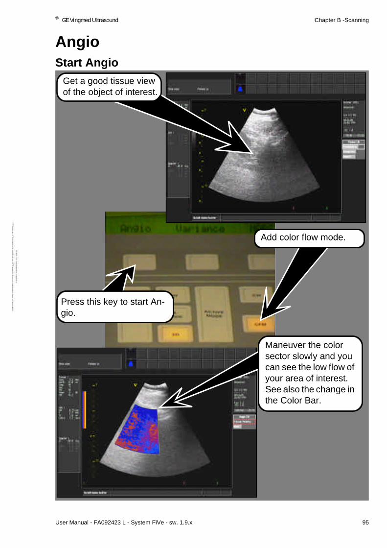
GE Vingmed Ultrasound Chapter B -Scanning
User Manual - FA092423 L - System FiVe - sw. 1.9.x 95
AngioStart Angio
Press this key to start An-gio.
Add color flow mode.
Get a good tissue view of the object of interest.
Maneuver the color sector slowly and you can see the low flow of your area of interest. See also the change in the Color Bar.

Chapter B -Scanning GE Vingmed Ultrasound
96 User Manual - FA092423 L - System FiVe - sw. 1.9.x
Angio
Power amplitude Doppler, Angio
Note that the term Color Flow is a generic term which includes the three Color Flow modes that are available in the system:
* Conventional Color Flow Mapping (Ref: page 81.)* Power Amplitude Doppler* Tissue Velocity Imaging (optional). See separate Manual.Power Amplitude Doppler, also known as Ultrasound Angio or Doppler Energy, uses the same data as acquired using Conventional Color Flow Mapping. In Power Ampli-tude Doppler it is the of the doppler signal amplitude that represents the intensity which is mapped to a color instead of the velocity, bandwidth and direction. Undesired signals from slowly moving tissue structures are surpressed by the same type of wall filter. Power Amplitude Doppler provides noticeably higher sensitivity because of much lower pulse repetition frequency and extensive temporal processing.
Tissue Velocity Imaging maps velocities from tissue motion to colors in accordance with a color map.

GE Vingmed Ultrasound Chapter B -Scanning
User Manual - FA092423 L - System FiVe - sw. 1.9.x 97
Traditional M-ModeStart M-Mode, duplex view
In 2D mode, press the ADD CURSOR/MODE key and position the cursor line on a tissue area of interest. Press this key to start 2D/M-Mode.
Shortly after, Duplex M-Mode replaces 2D.
About M-ModeIn Traditional M-Mode, Tissue Data is continual-ly gathered along the cur-sor line on the 2D image. Each recorded pulse is joined together and pre-sented horizontally within a rectangle which has a horizontal time scale and a vertical depth scale. It is normally used to scru-tinize found tissue abnor-malities on the 2D image.

Chapter B -Scanning GE Vingmed Ultrasound
98 User Manual - FA092423 L - System FiVe - sw. 1.9.x
Traditional M-Mode
Elements in duplex M-Mode display
Moving Erase bar is present while updating M-Mode in live mode.
The cursor line on the 2D image is reposi-tioned with the track-ball, if necessary.
The Depth scales aid you in pinpoint-ing occurrences of interest in the pre-sented situation.
Time scale.
The controls available for M-Mode perfection are the same as for 2D, apart from Horizontal sweep, which is de-scribed here.
Horizontal Sweep regulates the update rate of screen-dis-played M-mode.

GE Vingmed Ultrasound Chapter B -Scanning
User Manual - FA092423 L - System FiVe - sw. 1.9.x 99
Traditional M-Mode
Image size
Press this key to tog-gle between small or larger 2D image, de-pending on which size is displayed by default setting as de-scribed in Chapter A.

Chapter B -Scanning GE Vingmed Ultrasound
100 User Manual - FA092423 L - System FiVe - sw. 1.9.x
Anatomic M-ModePrepare for Anatomic M-Mode
Scroll through and study data from the Replay Buffer, using the trackball.
In 2D, as shown here, press Full Freeze and the M-MODE key direct-ly after to obtain Ana-tomic M-Mode.

GE Vingmed Ultrasound Chapter B -Scanning
User Manual - FA092423 L - System FiVe - sw. 1.9.x 101
Anatomic M-Mode
Maneuvering the cursor lineStill in full freeze status, press ADD CURSOR/MODE once to move activity to the 2D image and thereby access to cursor line maneuver.
When you stop maneu-vering these a display update of the M-Mode view at the new location of interest occurs.
Press ADD CURSOR/MODE once more to re-turn to normal M-Mode Replay buffer scrolling.
The Instruction Move Cursor is displayed at the left side of the lower edge of the screen.
Using the trackball, ma-neuver the line cursor, and position its sam-pling markers on an area of interest.

Chapter B -Scanning GE Vingmed Ultrasound
102 User Manual - FA092423 L - System FiVe - sw. 1.9.x
Anatomic M-Mode
Anatomic M-Mode viewing
Hint
Anatomic M-mode can be initiated in both 2D Tissue and 2D Color Flow modes.
After positioning the cur-sor and Sampling mark-ers, press the Select area, surrounding the trackball, once to toggle from Move Cursor activ-ity to Turn AMM Cursor.
At the new cursor posi-tion, maneuver the trackball, a new cursor line, that is anchored at the old cursors sam-pling marker, appears.
As you move the trackball, it rotates freely in the direc-tion of the move-ment. When you stop, an M-Mode redo at the new lo-cation occurs. At this stage do a sur-vey of the area in Anatomic M-Mode.

GE Vingmed Ultrasound Chapter B -Scanning
User Manual - FA092423 L - System FiVe - sw. 1.9.x 103
Anatomic M-Mode
About…
Anatomical M-Mode is a most useful tool for the validation and quantification of tissue movement and thickening. It is for instance possible to measure wall thickening in lo-cations where the wall boundary is parallel with the acoustic beams. The anatomical M-Mode applied to tissue velocity data provides the tool that resolves the complex motion characteristics of myocardial wall movement. The Anatomical M-Mode lines are sampled with the same temporal and spatial resolution as done with the 2D tis-sue or 2D color flow images, making it possible to produce high quality M-Mode im-ages from high framerate 2D acquisitions.

Chapter B -Scanning GE Vingmed Ultrasound
104 User Manual - FA092423 L - System FiVe - sw. 1.9.x
Color M-ModeSelect Color M-Mode
In 2D/M-Mode, press this key, to select Color M-Mode, and below shown color informa-tion, representing speed (movement), ap-pears.

GE Vingmed Ultrasound Chapter B -Scanning
User Manual - FA092423 L - System FiVe - sw. 1.9.x 105
Color M-Mode
Assignables, screen functions, live
Tissue Priority
Sample Volume
Baseline
Frequency
Radial Avg.
Power
ColorMMode
InformationFind missing Color M-Mode commands and adjustment de-scriptions in 2D, M-Mode and Color flow descriptions.
Sample Volume determines the size of the flow data gath-ering area.
Radial averaging is vertical data averaging to get smoother M-Mode flow.
WARNINGFrequency adjustment In Doppler or Col-or Flow modes affects the maximum size of the available velocity range. (Frequen-cy increase lowers the maximum.

Chapter B -Scanning GE Vingmed Ultrasound
106 User Manual - FA092423 L - System FiVe - sw. 1.9.x
Color M-Mode
Assignables, screen functions, FULL FREEZEInformationFind missing Color M-Mode com-mands and adjustment descrip-tions in 2D, M-Mode and Color flow descriptions.

GE Vingmed Ultrasound Chapter B -Scanning
User Manual - FA092423 L - System FiVe - sw. 1.9.x 107
Side by side viewingChoose side by side view
To present the new view, shown to the left, press the SELECT SCREEN key.
The default setting on the screen configura-tion menu, over/under, is the automatic choice when selecting duplex modes.
Repeat the above to return the default view.

Chapter B -Scanning GE Vingmed Ultrasound
108 User Manual - FA092423 L - System FiVe - sw. 1.9.x
DopplerStart PW Doppler Mode
From 2D mode, press this key to add Doppler from the region of inter-est marked by the TM cursor. The 2D picture is rescaled, and the Doppler Window ap-pears below it.

GE Vingmed Ultrasound Chapter B -Scanning
User Manual - FA092423 L - System FiVe - sw. 1.9.x 109
Doppler
Start Duplex CW Doppler
Depth scale in mm.
A time scale in sec-onds.
The ECG trace re-scaled to fit the Dop-pler window.
A Doppler center Baseline.
A velocity scale in m/s, (meters per sec-ond).
Press this key to start live Duplex CW Dop-pler shown below.
The 2D situation with continually adjust-able TM cursor and a depth scale.

Chapter B -Scanning GE Vingmed Ultrasound
110 User Manual - FA092423 L - System FiVe - sw. 1.9.x
Doppler
Carotid Angle CorrectionObtain a good image and engage the Cursor with the Add Mode/Cursor key.
To move the cursor to an-other position press the Select key once more.
Press one of the Doppler Mode keys and continue the investigation.
Press the Select key once, adjust the angle until the yellow line is parallel with the vessel wall or the assumed di-rection of flow.
Move the Cursor with the Trackball and place the Angle Correction marker, on the cursor sample volume, in the center of vessel.

GE Vingmed Ultrasound Chapter B -Scanning
User Manual - FA092423 L - System FiVe - sw. 1.9.x 111
Doppler
Peak Velocity Correction
Peak velocity Correction is used for finding a more correct maxi-mum velocity reading as a func-tion of Tilt Angle Correction, Sample Volume and Depth.
With the above situation the Automatic Peak Velocity Cor-rection is switched ON/OFF here.
When switched ON the Veloci-ty is corrected and the Doppler scale is Green.

Chapter B -Scanning GE Vingmed Ultrasound
112 User Manual - FA092423 L - System FiVe - sw. 1.9.x
Doppler
Sample Volume size change
Sample Volume Con-trols size of the doppler Sample Volume (Gate).
Increasing the sam-ple volume size im-proves sensitivity but reduces spatial resolution.
This also reduces the achievable maximum velocity range.
The horizontal paddle adjusts the Sample Vol-ume. The vertical pad-dle finds the Sample Volume

GE Vingmed Ultrasound Chapter B -Scanning
User Manual - FA092423 L - System FiVe - sw. 1.9.x 113
Doppler
Assignables, screen commands, live
Compress
Reject
Frequency
Framerate
Power
Angle Corr.
Doppler CW
Sample Volume
Compress
Reject
Frequency
Framerate
Tracking
Doppler PW
Overrange
Power
Angle Corr.
BaselineControls position of the zero velocity baseline of the spectral display. To be used to help avoid aliasing of the doppler display.
WARNINGFrequency adjustment In Doppler or Color Flow modes affect the maximum size of the available velocity range. Frequency increase lowers the maximum.

Chapter B -Scanning GE Vingmed Ultrasound
114 User Manual - FA092423 L - System FiVe - sw. 1.9.x
Doppler
Doppler Control descriptionsVelocity RangeControl the velocity range of the spectrum display.The requested velocity range will not necessarily be achievable. The available range depends on parameters like frequency, sample volume position and sample volume size. If the required range is not achievable reducing the sample volume size might help.When measuring high velocities one might get unlikely sample volumes. To get rid of these use either the LPRF control (this will lower the velocity range) or the Overrange control. The displayed velocity range depends on the setting of the Angle Correction.TrackingControls the spectral analyzers “tracking” of blood cells. When tracking is off (set to mini-mum value) the analyzer will work in the traditional way. Increasing the tracking will make the analyzer to try to “track” the blood cells. This will improve the resolution of the spectral display, and it makes it possible to measure velocity above the Nyquist velocity. But in-creasing the tracking will also reduce the sensitivity of the doppler. See also Overrange control.OverrangeIf overrange is on (value higher than minimum) the spectral analyzer analyzes velocities beyond the Nyquist velocity. This will make the measurement of high velocities possible without the drawback of unlikely sample volumes. To make it possible to distinguish the signal from blood moving with velocities beyond Nyquist velocities from ghosts from lower velocity signals tracking must be on (see Tracking control).

GE Vingmed Ultrasound Chapter B -Scanning
User Manual - FA092423 L - System FiVe - sw. 1.9.x 115
Doppler
Assignables, screen commands, FULL FREEZE
Find information from the Doppler scanning at this location on the screen.

Chapter B -Scanning GE Vingmed Ultrasound
116 User Manual - FA092423 L - System FiVe - sw. 1.9.x
Tape RecordingControl Panel VCR controls
Press this key to Record screen activities.
Press this key to Pause recording screen activities.
Press this key to Initiate Vid-eo Playback.
A set of VCR functions ap-pear at the switches and ro-taries.
These include Shuttle speed for manual ad-justment of video play-back speed.
Stop to halt video playback.When stop has been activiated, the LCD shows Eject
FF to move video playback Fast forward.
Press this key to play and display on screen the re-corded screen activities.
Press REW to rewind played VCR tape.

Chapter C
Applications
This section tells you about:
• User Defaults storage . . . . . . . . . . . . . . . . . . . . . . . . . . . . . . . . . . . . . 118
• System Five, SuperVision . . . . . . . . . . . . . . . . . . . . . . . . . . . . . . . . . . 120
• Biopsy Option . . . . . . . . . . . . . . . . . . . . . . . . . . . . . . . . . . . . . . . . . . . 126

Chapter C - Application GE Vingmed Ultrasound
118 User Manual - FA092423 L - System FiVe - sw. 1.9.x
User Defaults storageUser Defaults selection
IMPORTANTYour POWER control setting is not stored with your saved user default.
This function allows you to save and recall system adjustments and setups to add effectivity to your acquisition routines. How to do this follows.
Select the Probe, Scan the patient and adjust the system to optimize the scan.
To gain access to the Applications menu, press the APPLICATION key.
To open the User De-faults setup dialog, click- select User Defaults on the displayed Applica-tions Menu.
Here, you can Save settings under a file-name, Set as Default for present acquisi-tion, Deleted altogether or you can use FACTORY set instead.

GE Vingmed Ultrasound Chapter C - Application
User Manual - FA092423 L - System FiVe - sw. 1.9.x 119
User Defaults Storage
Save and Recall your user default
To return to the Users Defaults menu and click Set as Default which will make this setting the automatic choice the next time you choose Cardiac on the Applica-tion Menu.
Type your User Defaults identity as shown here and place the cursor onto Save and click it.
Your entered setup file-name appears on the list below the naming window.
To recall your default set-up, which in our example was in Cardiac acquisi-tion you can find your saved defaults file on the Settings Menu that ap-pears when you highlight Cardiac shown here. Oth-erwise, you must find it via the User Defaults menu.
Note If you have chosen your own setting its filename appears on the scanner info window, under the chosen application.

Chapter C - Application GE Vingmed Ultrasound
120 User Manual - FA092423 L - System FiVe - sw. 1.9.x
System Five, SuperVisionHandle EchoPAC on System FiVe
Some System Fives are shipped with an EchoPAC integration. These have added functionality within and SuperVision added to their product names. The following section describes how the integration affects normal System Five use. The EchoPAC integration boots at system boot-up.
Whenever you need to switch from System Five scanning and over to the EchoPAC program, press this key.
This keyboard covers most of your normal EchoPAC needs but some shortcuts may fail.
After selection, Echo-PAC display covers this area.
The Trackball and Select area function as your stand-alone mouse, and it’s Select key when EchoPAC is active.
This miniature monitor, found just above the key-board, continuously dis-plays the current EchoPAC situation.

GE Vingmed Ultrasound Chapter C - Application
User Manual - FA092423 L - System FiVe - sw. 1.9.x 121
System Five, SuperVision
Patient ID entry selectionTo do Patient ID entry on System FiVE with EchoPAC active, press this key.
This executes an automatic switch to the EchoPAC patient handling functions.
Here, you can choose this function to fulfill your ID entry task.
Find descriptions of the other functions here, in the EchoPAC User Manual.
Hint:To Eject Magneto Optical Disks from System FiVe press fn and e keys once.

Chapter C - Application GE Vingmed Ultrasound
122 User Manual - FA092423 L - System FiVe - sw. 1.9.x
System Five, SuperVision
Patient ID inputDo patient ID input as described in the Echo-PAC User Manual*.
After ID entry, you exit from it, and the Home screen appears on the screen showing your en-tered ID.
Shortly after the Sys-tem FiVe scan situa-tion appears showing the automatically en-tered ID at this loca-tion.
*Note:Please refer to these EchoPAC User manual Part Numbers:EP192010_D for 6.3.x sw ML292397_E for 5.4.x swML292223_I for 5.4.x sw

GE Vingmed Ultrasound Chapter C - Application
User Manual - FA092423 L - System FiVe - sw. 1.9.x 123
System Five, SuperVision
Special Setup functionsSwitch EchoPAC Video Grabbing ON when you want to do video grab-bing from the System Five video signal and transfer it to EchoPAC.
In live mode you get a raw data transfer of the scan activity on the screen. At full freeze you transfer the amount of rawda-
ta memorized by the System FiVe, or a normal copy of the present screen picture or a high resolution copy of the screen picture.
Select these to make the Footswitch work in EchoPAC only. Then the footswitch acts as it does on the EchoPAC stand-alone. See the EchoPAC User Manual for details.
The Transfer in detail is also dependent on oth-er setups on this menu.

Chapter C - Application GE Vingmed Ultrasound
124 User Manual - FA092423 L - System FiVe - sw. 1.9.x
System Five, SuperVision
Footswitch activity messages
When doing Continuous capture, from System FiVe to EchoPAC, display of the footswitch activity Status messages, for Grabbing and Pause ap-pear at this location.

GE Vingmed Ultrasound Chapter C - Application
User Manual - FA092423 L - System FiVe - sw. 1.9.x 125
System FiVe SuperVision
Willful System shut-Down with integrated Mac™
During normal everyday conditions, always use following shut-down routine:
-Set in standby-mode with Standby/ON key.
-Allow time for computer to clear up and organize it’s data and allow the system to come to rest in Stand-by mode.
-After this, switch power off with the Power ON/OFFswitch at the sys-tem rear.

Chapter C - Application GE Vingmed Ultrasound
126 User Manual - FA092423 L - System FiVe - sw. 1.9.x
Biopsy OptionIntroduction
Intended useThe biopsy option is intended for use by a duly licensed physician who has received the appropriate training in biopsy techniques as dictated by current relevant practices, as well as in proper operation of the System FiVe Ultrasound Scanner.
This device provides a mechanical means for doing needle / instrument guided proce-dures with the use of a diagnostic ultrasound probe. A reusable bracket is securely po-sitioned over the probe body allowing attachment and use of disposable needle guides. This device provides a fixed path for the needle or instrument that, when coupled by the ultrasound system software, corresponds to on-screen imaging guidelines for visualizing guided instrument placement procedures. Furnish the CIVCO Biopsy Needle Guide in-cludes transducer cover, which are disposable for single patient / procedure use, sterile. The single use, disposable feature helps to prevent transfer of microorganisms, body flu-ids, and particulate material to the patient and health care worker during reuse of the transducer. Furnish the reusable Biopsy bracket non-sterile, and clean it before each use to the user-required disinfection level.
Sterile Kit packaging.
Rubber Bands.
Sterile GEL sachet and Sterile Cover.
A Biopsy Bracket
A Probe.
A Needle Guide with revers-ible snap-on, snap-off, hole-channel piece.
A Biopsy Needle with pro-tection sheath.

GE Vingmed Ultrasound Chapter C - Application
User Manual - FA092423 L - System FiVe - sw. 1.9.x 127
Biopsy option
Bracket and Needle guide mounting (10MHz FLA-Feb.99)
WARNINGUse the utmost of care when you are mounting and dismounting the Bracket.
WARNING Avoid puncturing the ster-ile cover.
Mount the Bracket on the probe.
Drape the probewith bracket tightly us-ing the sterile cover from the Biopsy kit.
Add GEL to the probe scan face.
Caution Follow the texts on the right hand side step by step from top to bottom
Add some sterile Gel, from the Biopsy kit, to this area of the cover.
Remove any air bubbles that are trapped be-tween the sterile cover and the gel, before sealing the cover’s open end with sterile rub-ber bands from the kit.
Slide the fastener in place as shown here.
Tighten the fastener as shown here.
Gently snap the Needle Guide onto the Biopsy Bracket as shown here.

Chapter C - Application GE Vingmed Ultrasound
128 User Manual - FA092423 L - System FiVe - sw. 1.9.x
Biopsy option
Bracket and Needle Guide mounting (3.5MHz CLA)
Mount the bracket onto this side of the probe so that the three protru-sions on the inner side of the bracket rest in the three square groves on the probes housing. It is necessary to loosen the bracket fastener before the mounting and to fastening it again after-wards.
Gently snap the Nee-dle Guide onto the Biopsy Bracket as shown here.
WARNING Avoid puncturing the sterile cover.
WARNINGAvoid compromising sterile parts.
With sterile precautions, drape this probe and bracket as described on the previous page.

GE Vingmed Ultrasound Chapter C - Application
User Manual - FA092423 L - System FiVe - sw. 1.9.x 129
Biopsy option
Start the Biopsy OptionTo start the Biopsy Option, press this key on the Control Panel.
A Biopsy menu appears on the screen. It con-sists of click-selectable keys for Probe type/Nee-dle thickness selection.
The Biopsy guide lines replace the menu on the screen’s ultra-sound area. (1.0cm between large yellow dots, 0.5cm from large yellow dots to small yellow dots and 5.0cm between red dots).
Choose a needle with an appropriate gauge (14, 16, 18, 20 or 22) for the job. Press the appropriate needle key as input for the system.

Chapter C - Application GE Vingmed Ultrasound
130 User Manual - FA092423 L - System FiVe - sw. 1.9.x
Biopsy option
Determine Biopsy needle lengthTo determine the needed needle length, scan and find the best possible pas-sageway to the area of in-terest. When you find it, press Meas, the scanning halts and you can retrieve the situation from the Re-play memory.
Choose Biopsy Cal on this appearing menu.
On the the displayed Measure-ments menu, a measurement start point setting appears at a point where upward extended guide lines cross the leftward ex-tended 0 depth line of the scan.
Maneuver it until it reaches the point of in-terest. Press Select to mark the end point of the measurement.
Roll the trackball diag-onally downwards to the right and the green cursor appears.
Two measured distanc-es appear here. These are; Dist which is the distance between the point of interest and the 0 depth mark, and Nee-dle which is distance between the top of the needle guide and the point of interest.

Chapter D
Using M&A
This section tells you how to:
• M&A examples . . . . . . . . . . . . . . . . . . . . . . . . . . . . . . . . . . . . . 132
• M-Mode M&A . . . . . . . . . . . . . . . . . . . . . . . . . . . . . . . . . . . . . . 132
• Draw the first distance measurement . . . . . . . . . . . . . . . . . . . . 133
• Store measurement number one. . . . . . . . . . . . . . . . . . . . . . . . 134
• Repeat a measurement. . . . . . . . . . . . . . . . . . . . . . . . . . . . . . . 135
• Store the repeated measurement . . . . . . . . . . . . . . . . . . . . . . . 136
• Measure 2D Area in duplex M-Mode. . . . . . . . . . . . . . . . . . . . . 137
• Complete and store 2D area measurements . . . . . . . . . . . . . . 138
• Cardiac M&A Configuration. . . . . . . . . . . . . . . . . . . . . . . . . . . . 139
• Mode shifting during M&A . . . . . . . . . . . . . . . . . . . . . . . . . . . . . 140
• Report . . . . . . . . . . . . . . . . . . . . . . . . . . . . . . . . . . . . . . . . . . . . 141
• VCR M&A . . . . . . . . . . . . . . . . . . . . . . . . . . . . . . . . . . . . . . . . . 142
• 2D/M-Mode calibration . . . . . . . . . . . . . . . . . . . . . . . . . . . . . . . 146
• Cardiac Acquisition Formulas . . . . . . . . . . . . . . . . . . . . . . . . . . 153
• Cardiac Acquisition Parameters . . . . . . . . . . . . . . . . . . . . . . . . 157
• PV M&A: . . . . . . . . . . . . . . . . . . . . . . . . . . . . . . . . . . . . . . . . . . 161
• Start Ellipse measuring . . . . . . . . . . . . . . . . . . . . . . . . . . . . . . . 161
• Measurements & Ratios . . . . . . . . . . . . . . . . . . . . . . . . . . . . . . 179
• Cardiovascular Acquisition Formulas . . . . . . . . . . . . . . . . . . . . 180

Chapter D - Using M&A GE Vingmed Ultrasound
132 User Manual - FA092423 L - System FiVe - sw. 1.9.x
M&A examplesM-Mode M&A
To halt all scan activi-ty, press the FULL FREEZE key. This ac-tivates the 2D FREEZE key simulta-neously. The 2D FREEZE key can also be used to halt the 2D-sector only.
Using the trackball, run through the replay data, to find the Area of interest, and press the MEAS., or CALI-PER key.
On the Measure menu that appears alone, when you select MEAS. Beforehand, select M Cal, and the measuring menu, to-gether with the mea-suring cross appears on your screen. Mea-surement instructions appear in this area.

GE Vingmed Ultrasound Chapter D - Using M&A
User Manual - FA092423 L - System FiVe - sw. 1.9.x 133
M&A examples
Draw the first distance measurement
Using the Trackball and Select key area sur-rounding it, place the cross at a start point, as prompted by the soft-ware and press select to mark it.
Using the trackball Draw the measuring line as shown and press the Select key when you reach the end point.
At the assignable you will always find Mode related mea-surement types as shown here for M-Mode.

Chapter D - Using M&A GE Vingmed Ultrasound
134 User Manual - FA092423 L - System FiVe - sw. 1.9.x
M&A examples
Store measurement number oneYour first measurement turns red and gets num-bered at the top. Move onto the Measuring menu and highlight 1. Dist which holds the re-sult. Press the Select key.
This exits you to the Measuring menu again for selection of new activities.
A Storage menu ap-pears beside the measuring menu. Using the trackball find a storage loca-tion on it and press Select to confirm storage.

GE Vingmed Ultrasound Chapter D - Using M&A
User Manual - FA092423 L - System FiVe - sw. 1.9.x 135
M&A examples
Repeat a measurement
Place the cross at the start point and press Select.
The old mea-surement is moved down one position to make place for the next mea-surement.
To repeat a measure-ment select this menu function and a new cross appears at the center of the screen.
Hint!Press also the trackball surrounding select area to repeat measure-ments.

Chapter D - Using M&A GE Vingmed Ultrasound
136 User Manual - FA092423 L - System FiVe - sw. 1.9.x
M&A examples
Store the repeated measurement
The result is available on the Measuring menu. Store it as de-scribed previously.
As you arrive at the end point of your second measurement press the trackballSelect area.

GE Vingmed Ultrasound Chapter D - Using M&A
User Manual - FA092423 L - System FiVe - sw. 1.9.x 137
M&A examples
Measure 2D Area in duplex M-Mode
To measure 2D area se-lect Area on the Mea-surement types menu. A position on the mea-suring menu is made available and the previ-ous measurements are moved one place down-wards.
A cursor appears on the 2D image. Using the trackball move it to an area drawing start position, press Select and start tracing the 2D area, using track-ball movement in the correct direction.

Chapter D - Using M&A GE Vingmed Ultrasound
138 User Manual - FA092423 L - System FiVe - sw. 1.9.x
M&A examples
Complete and store 2D area measurements
When completed, exit from measuring M Cal.
Complete the Area trace and when you reach close to the start point press Select and the Area trace is auto-matically completed. Repeat, if necessary, and store as described previously.

GE Vingmed Ultrasound Chapter D - Using M&A
User Manual - FA092423 L - System FiVe - sw. 1.9.x 139
M&A examples
Cardiac M&A Configuration
Select CONFIG.
The Cardiac configu-ration menu appears with three configura-tions options.
Select Sp Calipers.
On the dialog that ap-pears configure Sp Cal-ipers and exit by saving or cancelling.

Chapter D - Using M&A GE Vingmed Ultrasound
140 User Manual - FA092423 L - System FiVe - sw. 1.9.x
M&A examples
Mode shifting during M&A
Mode Shifting during an M&A session is very easy and correct measurement types are always present for the active mode.
M&A is also available in other ap-plications and related measure-ment types are also presented.

GE Vingmed Ultrasound Chapter D - Using M&A
User Manual - FA092423 L - System FiVe - sw. 1.9.x 141
M&A examples
Report
To obtain a Measure-ment Report on this system, press this key on the control panel. The Report generator presents its opening screen.
In our examples we did M-Mode measure-ments. To see these, select M-Mode and they are presented as show here. If this Patient file is moved to an external storage, these mea-surements will follow, providing the correct name is noted for the investigation.

Chapter D - Using M&A GE Vingmed Ultrasound
142 User Manual - FA092423 L - System FiVe - sw. 1.9.x
VCR M&AAbout VCR M&A
On System FiVe you can do M&A on VCR recorded scan data from single or duplex modes. You are automatically asked to calibrate VCR scan data from single or duplex modes. You can choose to use existing calibrations from single or duplex modes. The M&A Function, when used on VCR data, is always related to the systems active probe and selected application and not the ones that were used during this particular vcr recording. You may however change application and gain access to the measurement types that you intended to use.
The VCR Calibrate menu, the M&A control panel tools and a dis-played VCR situation that is ready for M&A.
When no tape is in-serted this on the sceen at this location will remind you

GE Vingmed Ultrasound Chapter D - Using M&A
User Manual - FA092423 L - System FiVe - sw. 1.9.x 143
VCR M&A
2D VCR Calibrate
After initiating a video replay of VCR recorded data, press the MEAS., or Calipers key on the control panel.
On the VCR Calibrate menu select the 2D po-sition with the Trackball and the Select area sur-rounding it.
The menu is removed, a cursor appears on the 2D situation and what to do next is continually updated at this location, as you proceed.

Chapter D - Using M&A GE Vingmed Ultrasound
144 User Manual - FA092423 L - System FiVe - sw. 1.9.x
VCR M&A
Enter the 2D calibration data
As instructed, place the cursor onto the dis-played depth scale and mark the start point of your calibration line.
Using the trackball move the cursor to an-other position on the depth scale and mark it as an end point with the select area.
On the length input dialog that appears, enter a depth. In our example, this is 15 (cm).
Press Ok to enter input and proceed. Press Cancel to exit from calibra-tion.

GE Vingmed Ultrasound Chapter D - Using M&A
User Manual - FA092423 L - System FiVe - sw. 1.9.x 145
VCR M&A
Ready for 2D M&A The Ok input leads you to proceed with M&A using the measurement types that are forward-ed by the system. If the application and dis-played measurement types are wrong for the displayed data, recall the VCR Calibrate menu, select M&A Package and proceed as described on page D1-151.

Chapter D - Using M&A GE Vingmed Ultrasound
146 User Manual - FA092423 L - System FiVe - sw. 1.9.x
VCR M&A
2D/M-Mode calibration
In Duplex mode calibra-tion, which in our exam-ple is 2D/M-Mode, select either 2D/M-Mode or 2D/Doppler on the menu.
The system cursor ap-pears once again on the 2D part of the scene and the system asks you to use it to draw a rectan-gle to mark the 2D area.

GE Vingmed Ultrasound Chapter D - Using M&A
User Manual - FA092423 L - System FiVe - sw. 1.9.x 147
VCR M&A
Calibrate the 2D area
To mark the 2D area, place the cursor at a start point, mark it, move the cursor in a di-agonal direction to a new position simulta-neously pulling out a rectangle and mark the new point of the area.
As instructed here, place the cursor at 0cm position on the depth scale se-lect it as a line start point. Move the cursor, position it at 15cm on the scale and mark it as a line end point.
A Length input dialog appears. Enter the line length as shown here and press Ok to store it and exit to M-Mode calibration or Cancel to exit from M&A.

Chapter D - Using M&A GE Vingmed Ultrasound
148 User Manual - FA092423 L - System FiVe - sw. 1.9.x
VCR M&A
Mark the M-Mode area
Do this in the exact same manner as de-scribed for marking the 2D area and end up with a rectangle that resembles this.
When 2D sector is cali-brated you are asked to mark the M-Mode area.

GE Vingmed Ultrasound Chapter D - Using M&A
User Manual - FA092423 L - System FiVe - sw. 1.9.x 149
VCR M&A
Calibrate the M-Mode area Time scale
The next step is to cal-ibrate the M-Mode time lapse. To do this place the cursor onto 0 secs and press select. Move the cursor onto 4 secs mark and press select again. A white line is now drawn along the time scale.
The seconds entry dialog appears for you to enter the specific number.

Chapter D - Using M&A GE Vingmed Ultrasound
150 User Manual - FA092423 L - System FiVe - sw. 1.9.x
VCR M&A
Calibrate the M-Mode area depth scale
Hint!Autotrace is not avail-able in VCR M&A.
The M&A options for in this case 2D/M-Mode are displayed and you can continue.
On the entry dialog enter 15 and select Ok to do M&A or Cancel to exit.
Once more you are asked to measure depth but this time it concerns the M/Mode view. So place the cursor on 0cm marker and press se-lect. Repeat this at the 15cm marker.

GE Vingmed Ultrasound Chapter D - Using M&A
User Manual - FA092423 L - System FiVe - sw. 1.9.x 151
VCR M&A
M&A Package for application changeTo change application in VCR M&A, click-select M&A Package on the VCR Calibrate menu.
On this input the system presents a set of applications. Highlight and select one that suits your displayed VCR recorded data.

Chapter D - Using M&A GE Vingmed Ultrasound
152 User Manual - FA092423 L - System FiVe - sw. 1.9.x
VCR M&A
The Calibration Marker The Calibration Marker is automati-cally generated in re-corded data when there is a change of velocities in the Spectrum data.
The velocity scale/calibration is valid for measurements in the marked area. This is true as long as the Replay marker is positioned in the same area.
Replay marker
Replay marker
Velocity Scale

GE Vingmed Ultrasound Chapter D - Using M&A
User Manual - FA092423 L - System FiVe - sw. 1.9.x 153
Cardiac Acquisition FormulasIn addition to the parameters that are directly measured by a user, the System FiVe has a number of Formulas which are automatically calculated as soon as all of the parameters in the Formulas have been assigned. The labels in the for-mulas below, are the same as the labels listed in the parameter menus for as-signment.
Body Surface Area
BSA = (Patient Browser Entry)
BSA
(Patient Browser Entry)
2D - measurements
Volume
Volume by length-area =
Volume by Simpson =
When calculating volume by Simpson, the Volume is sliced up in 20 slices perpen-dicular to the long-axis. The h in the formula is the thickness of the slice, and D is the diameter.
Left Ventricular study
2D-Left Ventricular Ejection Fraction =
m2[ ] 0.007184 Height cm[ ]0.725( ) Weight kg[ ]0.425( )××
Basedonweight Weight3 kg[ ])(2
0.1•=
cm3[ ] 8 Area cm
2[ ]( )2
×3 Π Dist cm[ ]××--------------------------------------------
cm3[ ] Π h cm[ ] D cm[ ]2××
4----------------------------------------------------
1
20
∑
LeftVentricularVolumeEndDiastole cm3[ ] LeftVentricularVolumeEndSystole cm3[ ]–LeftVentricularVolumeEndDiastole cm3[ ]
---------------------------------------------------------------------------------------------------------------------------------------------------------------------------------------------------------------------------------

Chapter D - Using M&A GE Vingmed Ultrasound
154 User Manual - FA092423 L - System FiVe - sw. 1.9.x
Cardiac Acquisition FormulasLV Mass
M - Mode measurements
Left Ventricular-study
M-Mode Left Ventricular Ejection Fraction =
Fractional Shortening[%] =
LV MASS
(Report)
LA/AO ratio = (Report)
E/A ratio =
a1 LeftVentricleEpcardialArea
a2 LeftVentricleEndocardialArea
ba2π
------ ta1π
------ b–==
=
=
DLVMass 1.05=56--- a1{[× LeftVentricalEndocardialLength( t )}+ a2 LeftVentricaleEndocardialLength }×{– ]×
LeftVentricularDiameterEndDiastole cm[ ]3 LeftVentricularDiameterEndSystole cm[ ]) 3(–LeftVentricularDiameterEndDiastole cm[ ]3
-------------------------------------------------------------------------------------------------------------------------------------------------------------------------------------------------------------------------------------------------
100LeftVentricularDiameterEndDiastole cm[ ] LeftVentricularDiameterEndSystole cm[ ]–
LeftVentricularDiameterEndDiastole cm[ ]--------------------------------------------------------------------------------------------------------------------------------------------------------------------------------------------------------------------------------------×
LVMass 1.04x IVSd(( LVPWd LVDd+ )3 LVDd 3 )– 13.6–+=
LeftAtrialDiameterEndSystole cm[ ]AorticDimensionEndDiastole cm[ ]----------------------------------------------------------------------------------------------
MVe Evelocity( ) m s⁄[ ]MVa Avelocity( ) m s⁄[ ]-----------------------------------------------------------

GE Vingmed Ultrasound Chapter D - Using M&A
User Manual - FA092423 L - System FiVe - sw. 1.9.x 155
Cardiac Acquisition FormulasTeich holz:
Doppler Spectrum measurements
Calipers
The pressure is calculated as follows:
P[mmHg] =
Cardiac Output
Pmax[mmHg] = .
Vmean =
Pmean[mmHg] =
Velocity Trace Integral =
Heart Rate[BPM] =
Cardiac Output =
where Vavg = vti/TBB (vti i [m])
EDVtz cm3[ ] 7.02.4 LVDd cm[ ]+------------------------------------------ LVDd 3•=
ESVtz cm3[ ] 7.02.4 LVDs cm[ ]+----------------------------------------- LVDs cm[ ]3•=
SVtz cm3[ ] EDVtz ESVtz–=
EFtzESVtzEDVtz-----------------=
COtz SVtz HR•=
4 Vms----
2×
4 Vmaxms----
2×
ms---- 1
TimeOfEnvelope s[ ]---------------------------------------------------- V
ms----
0
TimeOfEnvelope s[ ]
∫× td
1TimeOfEnvelope s[ ]---------------------------------------------------- 4 v
ms----
2td×
0
TimeOfEnvelope s[ ]
∫×
cm[ ] Vms---- td
0
TimeOfEnvelope s[ ]
∫
60TimeBetweenBeats s[ ]----------------------------------------------------------
lmin--------- 6 Π Diameter cm[ ]
2-------------------------------------
2×× Vavg
ms----×

Chapter D - Using M&A GE Vingmed Ultrasound
156 User Manual - FA092423 L - System FiVe - sw. 1.9.x
Cardiac Acquisition Formulas
Shunt Ratio:
Pressure Half Time
Pressure Half Time is calculated automatically.
PHT[s] = time to reach
Mitral Valve Area =
Mitral Valve Area By Continuity Equation =
(Report)
Aortic Valve Area By Continuity Equation =
(Report)
Aortic Valve Area From Vmax =
(Report)
ShuntRatioPVvti π PA 2 )⁄( 2•(•
AVvti π Ao 2 )⁄( 2••-------------------------------------------------------=
1
2 Vmaxms----×
--------------------------------------
cm2[ ] 0.22
MitralValvePressureHalfTime s[ ]-----------------------------------------------------------------------------------------
cm2[ ]
Π LeftVentrOutflowTractDiam cm[ ]2
----------------------------------------------------------------------------------------- 2 LeftVentOutflowTractVelocityTraceIntegral cm[ ]
MitralValveVelocityTimeIntegral cm[ ]------------------------------------------------------------------------------------------------------------------------------------××
cm2[ ]
Π LeftVentrOutflowTractDiam cm[ ]2
----------------------------------------------------------------------------------------- 2 LeftVentrOutflowTractVelocityTraceIntegral cm[ ]
AorticValveVelocityTimeIntegral cm[ ]---------------------------------------------------------------------------------------------------------------------------------------××
cm2[ ]
Π LeftVentrOutflowTractDiam cm[ ]2
----------------------------------------------------------------------------------------- 2
LeftVentrOutflowTractPeakVelocityms----
AorticValvePeakVelocityms----
------------------------------------------------------------------------------------------------------------××

GE Vingmed Ultrasound Chapter D - Using M&A
User Manual - FA092423 L - System FiVe - sw. 1.9.x 157
Cardiac Acquisition ParametersMitral ValveName Label Unit Description Mode
MVVMX MV m/s Mitral Valve Peak VelocityMVVME MVmn m/s Mitral Valve Mean VelocityMVVR MR m/s Mitral Valve Regurgitant VelocityMVVMER MRmn m/s Mitral Valve Mean Regurg. VelocityMVACF MV m/s2 Mitral Valve Flow AccelerationMVPMX MV mmHg Mitral Valve Peak PressureMVPME MVmn mmHg Mitral Valve Mean PressureMVPR MRp mmHg Mitral Valve Regurgitant PressureMVPMER MRpmn mmHg Mitral Valve Mean Regurg. PressureSMVA MVA cm2 Mitral Valve Area (from Spectrum)2MVA MVA cm 2 Mitral Valve Area (from 2d)MVAVTI MVAvti cm2 Mitral Valve Area (from VTI)MVPHT MVpht ms Mitral Valve Pressure HalftimeMVVTI MVvti cm Mitral Valve Velocity Time IntegralMVCO MV l/min Mitral Valve Cardiac OutputMVTTP MVtpk sec Mitral Valve Time To PeakMVDSE EPSS cm Mitral Valve S-E distanceMVE MVEX cm Mitral Valve ExcursionMVSEF MVe-f cm/s Mitral Valve E-F SlopeMVD MV cm Mitral Valve Diameter
Tricuspid ValveName Label Unit Description Mode
TVVMX TV m/s Tricuspid Valve Peak VelocityTVVME TVmn m/s Tricuspid Valve Mean VelocityTVVR TR m/s Tricuspid Valve Regurgitant VelocityTVVMER TRmn m/s Tricuspid Valve Mean Regurg. VelocityTVACF TV m/s2 Tricuspid Valve Flow AccelerationTVPMX TV mmHg Tricuspid Valve Peak PressureTVPME TV mmHg Tricuspid Valve Mean PressureTVPR TRp mmHg Tricuspid Valve Regurgitant PressureTVPMER TRpmn mmHg Tricuspid Valve Mean Regurg. PressureTVPHT TVpht ms Tricusp Valve Pressure HalftimeTVVTI TVvti cm Tricuspid Valve Velocity Time IntegralTVCO TV l/min Tricuspid Valve Cardiac OutputTVTTP TVtpk sec Tricuspid Valve Time To PeakTVD TV cm Tricuspid Valve Diameter

Chapter D - Using M&A GE Vingmed Ultrasound
158 User Manual - FA092423 L - System FiVe - sw. 1.9.x
Pulmonic ValveName Label Unit Description Mode
PVVMX PV m/s Pulmonic Valve Peak VelocityPVVME PVmn m/s Pulmonic Valve Mean VelocityPVVI PI m/s Pulmonic Valve Insufficience VelocityPVVMER PImn m/s Pulmonic Valve Mean Insufficience VelocityPVACF PV m/s2 Pulmonic Valve Flow AccelerationPVPMX PV mmHg Pulmonic Valve Peak PressurePVPME PVmn mmHg Pulmonic Valve Mean PressurePVPI PIp mmHg Pulmonic Valve Insufficience PressurePVPMEI PIpmn mmHg Pulmonic Valve Mean Insuff. PressurePVVTI PVvti cm Pulmonic Valve Velocity Time IntegralPVCO PV l/min Pulmonic Valve Cardiac OutputPVTTP PVtpk sec Pulmonic Valve Time To PeakPVD PV cm Pulmonic Valve Diameter
Aortic ValveName Label Unit Description Mode
AVVMX AV m/s Aortic Valve Peak VelocityAVVME AVmn m/s Aortic Valve Mean VelocityAVVI AI m/s Aortic Valve Insuff. VelocityAVVMER AImn m/s Aortic Valve Mean Insufficience VelocityAOPHTR ARpht ms Aortic Valve Regurg. Pressure HalftimeAVACF AV m/s2 Aortic Valve Flow AccelerationAVPMX AV mmHg Aortic Valve Peak PressureAVPME AVmn mmHg Aortic Valve Mean PressureAVPI AIp mmHg Aortic Valve Insuff. PressureAVPMEI AIpmn mmHg Aortic Valve Mean Insuff. PressureAVVTI AVvti cm Aortic Valve Velocity Time IntegralAVCO AV l/min Aortic Valve Cardiac OutputAVTTP AVtpk sec Aortic Valve Time To PeakMAVDED Ao cm Aortic Dimension (ed) (from M-mode)2AVD Ao cm Aortic Dimension (from 2d)MAVD AV cm Aortic Valve Diameter (from M-mode)AVA AVA cm 2 Aortic Valve AreaAVAVTI AVAvti cm Aortic Valve Area (from VTI)AVAVMX AVAvmx cm Aortic Valve Area (from Vmax)
Left VentricularName Label Unit Description Mode
LVOTVMX LVOT m/s Left Ventricular Outflow Tract Peak VelocityLVOTD LVOT cm Left Ventricular Outflow Tract DiameterLVOTVTI LVOTvt cm Left Ventricular Outflow Tract Velocity Trace IntegralLVOTVME LVOTmn m/s Left Ventricular Outflow Tract Mean VelocityLVOTCO LVOT l/min Left Ventricular Outflow Tract Cardiac OutputLVOTPMX LVOT mmHg LVOT Peak PressureLVOTPME LVOTmn mmHg LVOT Mean Pressure

GE Vingmed Ultrasound Chapter D - Using M&A
User Manual - FA092423 L - System FiVe - sw. 1.9.x 159
LVET LVET sec Left Ventricular Ejection TimeMLVDED LVDd cm Left Ventricular Diameter (ed) (from M-mode)2LVDED LVDd cm Left Ventricular Diameter (ed) (from 2d)LVPWED LVPWd cm Left Ventricular Posterior Wall (ed)LVAED LVAd cm 2 Left Ventricular Area (ed)LVAEN LVAend cm2 Left Ventricular Area (endo) in LVmass(2d)LVAEP LVAepi cm 2 Left Ventricular Area (epi) in LVmass(2d)LVVED LVVd ml Left Ventricular Volume (ed)MLVDES LVDs cm Left Ventricular Diameter (es) (from M-mode)2LVDES LVDs cm Left Ventricular Diameter (es) (from 2d)LVVES LVVs ml Left Ventricular Volume (es)LVPWES LVPWs cm Left Ventricular Posterior Wall (es)LVAES LVAs cm 2 Left Ventricular Area (es)LVPW LVPW cm Left Ventricular Posterior Wall2LVEF LVEF Left Ventricle Ejec Frac (from 2d)MLVEF LVEF Left Ventricle Ejec Frac (from M-mode)LVFS %FS % Left Ventricle Fractional ShorteningLVM LVmass g Left Ventricle Mass2LVM LVmass(AL) g Left Ventricle Mass 2D Area-Length MethodLVDEN LVDend cm Left Ventricular Length (endo)(from2D)
Right VentricularName Label Unit Description Mode
RVET RVET sec Right Ventricular Ejection TimeMRVDED RVDd cm Right Ventricular Dimension (ed) (from M-mode)2RVDED RVDd cm Right Ventricular Dimension (ed) (from 2d)RVVED RVVd ml Right Ventricular Volume (ed)2RVDES RVDs cm Right Ventricular Dimension (es) (from 2d)MRVDES RVDs cm Right Ventricular Dimension (es) (from M-mode)RVVES RVVs ml Right Ventricular Volume (es)
Left AtrialName Label Unit Description Mode
LAD LAD cm Left Atrial DimensionLADES LADs cm Left Atrial Dimension (es)LAV LAV ml Left Atrial Volume
Right AtrialName Label Unit Description Mode
RAV R AV ml Right Atrial Volume
E/AName Label Unit Description Mode
MVVE MVe m/s E Velocity in E/AMVVA MVa m/s A Velocity in E/AIVRT IVRT [ms] ISO Volumetric Relaxation TimeMVTAC aT [ms] Mitral Valve Acceleration Time

Chapter D - Using M&A GE Vingmed Ultrasound
160 User Manual - FA092423 L - System FiVe - sw. 1.9.x
MVTDC DT [ms] Mitral Valve Deceleration TimeMVEAR E/A MVe/MVa Dimension Ratio
??Name Label Unit Description Mode
TBB Tb-b sec Time Between HeartbeatsHR HR BPM Heart Rate
Inter VentricularIndex Name Label Unit Description Mode
IVSDED IVSd cm Inter Ventricular Septum (ed) M-modeIVSDES IVSs cm Inter Ventricular Septum (es) M-modeIVSD IVS cm Inter Ventricular Septum 2DTQAV AVq-o sec Time from Q-wave to Aortic Valve opensTQPV PVq-o sec Time from Q-wave to Pulmonic Valve opens
LA/AOName Label Unit Description Mode
LAAOR LA/AO LA/AO Dimension Ratio
WEIGHT, HEIGHT, BSA (Pat. browser)Name Label Unit Description Mode
WEIGHT Weight kg Patient WeightHEIGHT Height cm Patient HeightBSA B.S.A m2 Body Surface Area

GE Vingmed Ultrasound Chapter D - Using M&A
User Manual - FA092423 L - System FiVe - sw. 1.9.x 161
PV M&A:Start Ellipse measuring
To start Ellipse measur-ing in PV M&A, when you have found a scan view of interest, press FULL FREEZE then MEAS and the measur-ing menu appears for you to select Ellipse.
The Measurements menu, for the Ellipse measurement, appears, together with a green cursor, in the scan area.
Place the cursor at a position on your area of interest from where you can start drawing an ellipse axis and press Select to mark the start point of it.

Chapter D - Using M&A GE Vingmed Ultrasound
162 User Manual - FA092423 L - System FiVe - sw. 1.9.x
PV M&A
Make the ellipseUsing the trackball, move the cursor to-wards the end point of this longitudinal ellipse axis and press select once more when you meet it.
Using the trackball once more, move it as shown here, diagonally downwards to the left, and your ellipse starts to appear.
Keep moving it until the ellipse covers your measurement area of interest. When it is cov-ered, press Select once more. The ellipse turns red and automat-ically calculated mea-surements from it appear in the measure-ments menu.
As you proceed with a function your next step is always prompted here by the system.

GE Vingmed Ultrasound Chapter D - Using M&A
User Manual - FA092423 L - System FiVe - sw. 1.9.x 163
Volume M&A, Tissue, Bladder and Thyroid Start Volume M&A
The Volume M&A’s are very much alike and sim-ilar to use. To prepare for any one of them, obtain the correct probe, scan the patient and press FULL FREEZE and then MEAS keys, at a sight of interest
Start them from this menu that appears.
Continue in this manner until all are measured.
A measuring cursor ap-pears on the screen along with a measure-ments menu to the left where three are shown vacant and awaiting entries from your mea-surements.
Place the cursor in ac-cordance with instruc-tions here, press Select to choose a start point and do the measurement.
HintVolume M&A is independent of continuous measuring. You may start mea-suring, measure length and width, exit from M&A and continue scanning. If you then re-enter M&A and measure the height your volume calculation will be completed.

Chapter D - Using M&A GE Vingmed Ultrasound
164 User Manual - FA092423 L - System FiVe - sw. 1.9.x
Volume M&A, Tissue, Bladder and Thyroid
Save Volume M&A Results
When completed, the volume is presented be-low the measurements on the measuring menu.
Volume Formulas:These are as shown below
TissueVolume π6--- length width height×××
BladderVolume 0.7 length width height×××ThyroidVolume 0.479 length width height×××=
=
=
Save these to the re-port.

GE Vingmed Ultrasound Chapter D - Using M&A
User Manual - FA092423 L - System FiVe - sw. 1.9.x 165
Hip Angle M&AStart Hip Angle M&AThis is Fetal M&A with ul-trasound. It allows you to uncover fetal abnormali-ties.at an early stage. Scan your patient with the correct probe, obtain and study a good fetal view before selecting to start Measurements.
The Hip Angle Function is located on this menu. To start hip angle M&A highlight and choose it on the menu using the Trackball and Select key
Place the appearing cursor onto the starting point of the first angular measurement, as in-structed along the lower edge of the screen and press select to mark it. With trackball move-ment, direct the cursor at the instructed angle. The reading appears on the left hand measure-ment menu.

Chapter D - Using M&A GE Vingmed Ultrasound
166 User Manual - FA092423 L - System FiVe - sw. 1.9.x
Hip Angle M&A
Complete Measurements and Save results
When all measure-ments are completed, an angular calculation is displayed on the Measurement menu. Store or assign it.
Place the starting point and do the second an-gular measurement as continuously instructed along the lower edge.
When this is completed, execute the third. It is not uncommon to dis-cover that all angle are less than 90 degrees

GE Vingmed Ultrasound Chapter D - Using M&A
User Manual - FA092423 L - System FiVe - sw. 1.9.x 167
OBGYN M&A SetupSelect the Measurement type
On the Table selection menu select the OBG-YN table type of your choice as shown here and select Save.
Cancel forgets your selection.
Select OB CONFIG-URE and the BPD measurement as an example.
With the OB applica-tion selected, choose CONFIG on the Measure menu.

Chapter D - Using M&A GE Vingmed Ultrasound
168 User Manual - FA092423 L - System FiVe - sw. 1.9.x
OBGYN M&A Setup
Do the Measurement
This is included on the OBGYN report Page-where you can see that our two measure-ments have been av-eraged to give safer age and closer date of delivery.
Do Biparietal Diameter measurements as de-cided previously and repeat if necessary.This gives automatic calculation of Gesta-tional Age GA and Esti-mated Date of Delivery EDD.

GE Vingmed Ultrasound Chapter D - Using M&A
User Manual - FA092423 L - System FiVe - sw. 1.9.x 169
OBGYN M&A Calculation FormulasGestational Age (week+days) using Femur LengthFL(GA) via ASUMFL range: 1.0 –7.9 cm
Assosiated standard deviation:
FL(GA) via HadlockFL range: 0.7 –8.2 cm
Assosiated standard deviation:
FL(GA) via HansmanFL range: 2.0 –7.5 cm
Assosiated standard deviation:
FL(GA) via HohlerFL range: 0.1 –8.7 cm
Assosiated standard deviation:
FL(GA) via JeantyFL range: 1.0 –8.0 cm
FL5*000003583.0FL4*00009128.0FL3*0008605.0FL2*1912.0FL*262.238.10 +−+++=Ga
FL*42.019.0 +=Sd
FL2*17.0FL*46.235.10 ++=Ga
Sd=1.0+0.26*FL
FL5*001861.0FL4*3495.0FL3*2492.0FL2*6631.0FL*728.379.10 +−+−+=Ga
FL*412.019.0 +=Sd
FL2*159947.0FL*670895.2174068.9 ++=Ga
FL*42.019.0 +=Sd
FL3*0009513.0FL2*0890988.0FL*05168.3421153.9 +++=Ga

Chapter D - Using M&A GE Vingmed Ultrasound
170 User Manual - FA092423 L - System FiVe - sw. 1.9.x
OBGYN M&A Calculation FormulasAssosiated standard deviation:
FL(GA) via O’BrienFL range: 1.0 –7.9 cm
Assosiated standard deviation:
70.2=Sd
FL5*004815.0FL4*116949.0FL3*041302.1FL2*99398.3FL*844899.9184726.5 +−+−+=Ga
FL*42.019.0 +=Sd

GE Vingmed Ultrasound Chapter D - Using M&A
User Manual - FA092423 L - System FiVe - sw. 1.9.x 171
OBGYN M&A Calculation Formulas
Gestational Age (week+days) using Biparietal Diameter
BPD(GA) via ASUMBPD range: 2.0 –9.8 cm
Assosiated standard deviation:
BPD(GA) via CampbellBPD range: 2.1 –9.4 cm
Assosiated standard deviation:
BPD(GA) via Eik-NesBPD range: 2.5 –10.1 cm
Assosiated standard deviation:
BPD(GA) via HadlockBPD range: 1.5 –10.1 cm
Assosiated standard deviation:
BPD5*005114.0BPD4*1359.0BPD3*377.1BPD2*492.6BPD*03.17269.5 +−+−+−=Ga
BPD*331.0125.0 +−=Sd
BPD5*002448.0BPD4*0522160.0BPD3*387842.0BPD2*9873671.0BPD*4510590.2363446.9 +−+−+=Ga
BPD*253.0643.0 +=Sd
BPD5*00004305.0BPD4*004395.0BPD3*0709.0BPD2*2468.0BPD*522.3035.2 +−−++=Ga
BPD*33.0125.0 +−=Sd
BPD3*000008771.0BPD*26345.08954.6 ++=Ga
BPD*253.0643.0 +=Sd
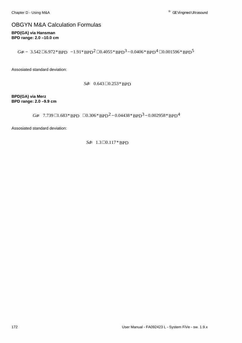
Chapter D - Using M&A GE Vingmed Ultrasound
172 User Manual - FA092423 L - System FiVe - sw. 1.9.x
OBGYN M&A Calculation FormulasBPD(GA) via HansmanBPD range: 2.0 –10.0 cm
Assosiated standard deviation:
BPD(GA) via MerzBPD range: 2.0 –9.9 cm
Assosiated standard deviation:
BPD5*001596.0BPD4*0406.0BPD3*4055.0BPD2*91.1BPD*972.6542.3 +−+−+−=Ga
BPD*253.0643.0 +=Sd
BPD4*002958.0BPD3*04438.0BPD2*306.0BPD*683.1739.7 −−++=Ga
BPD*117.03.1 +=Sd

GE Vingmed Ultrasound Chapter D - Using M&A
User Manual - FA092423 L - System FiVe - sw. 1.9.x 173
OBGYN M&A Calculation Formulas
Gestational Age (week+days) using Crown Rump Length
CRL(GA) via HansmanCRL range: 0.6 –15.0 cm
Assosiated standard deviation:
CRL(GA) via RobinsonCRL range: 0.6 –7.8 cm
Assosiated standard deviation:
CRL5*000005078.0CRL4*0007966.0CRL3*02904.0CRL2*3868.0CRL*822.2555.4 +−+−+−=Ga
CRL*098.081.0 +=Sd
CRL5*0004623.0CRL4*011622.0CRL3*117067.0CRL2*6356975.0CRL*8007.2933912.4 +−+−+−=Ga
CRL*098.081.0 +=Sd

Chapter D - Using M&A GE Vingmed Ultrasound
174 User Manual - FA092423 L - System FiVe - sw. 1.9.x
OBGYN M&A Calculation Formulas
Gestational Age (week+days) using Head Circumference
HC(GA) via CampbellHC range: 11.0 –34.8 cm
Assosiated standard deviation:
HC(GA) via HadlockHC range: 6.7 –35.0 cm
Assosiated standard deviation:
HC(GA) via HansmanHC range: 14.0 –35.0 cm
Assosiated standard deviation:
Assosiated standard deviation:
HC(GA) via MerzHC range: 7.6 –36.1 cm
Assosiated standard deviation:
HC4*00008253.0HC3*005916.0HC2*1546.0HC*8894.083.11 +−+−=Ga
HC*4.02.1 +=Sd
HC2*0003.0HC*54.096.8 ++=Ga
HC*008.010.3 −=Sd
HC5*000001944.0HC4*0002935.0HC3*01505.0HC2*3522.0HC*033.337.22 ++−+−=Ga
HC*008.010.3 −=Sd
HC4*00001634.0HC3*0009649.0HC2*02711.0HC*4014.0779.7 +−++=Ga
HC*3.04.0 +=Sd

GE Vingmed Ultrasound Chapter D - Using M&A
User Manual - FA092423 L - System FiVe - sw. 1.9.x 175
OBGYN M&A Calculation Formulas
Gestational Age (week+days) using Abdominal Circum-ference
AC(GA) via ASUMAC range: 3.5 –37.7 cm
Assosiated standard deviation:
AC(GA) via CampbellAC range: 8.6 –36.0 cm
Assosiated standard deviation:
AC(GA) via HadlockAC range: 5.1 –40.0cm
Assosiated standard deviation:
AC(GA) via HansmanAC range: 5.3 –32.0 cm
Assosiated standard deviation:
AC5*010000000028.0AC4*0000002614.0AC3*000009226.0AC2*0001584.0AC*8784.0958.6 +++−+=Ga
AC*06155.06129.0 +=Sd
AC3*0003847.0AC2*022174.0AC*277832.1490188.4 +−+=Ga
AC*048.031.1 +=Sd
AC2*0036.0AC*753.014.8 ++=Ga
AC*048.031.1 +=Sd
AC5*000001314.0AC4*0001004.0AC3*002514.0AC2*01746.0AC*9061.0427.7 +++−+=Ga
AC*048.031.1 +=Sd

Chapter D - Using M&A GE Vingmed Ultrasound
176 User Manual - FA092423 L - System FiVe - sw. 1.9.x
OBGYN M&A Calculation FormulasAC(GA) via JeantyAC range: 5.7 –31.6 cm
Assosiated standard deviation:
AC(GA) via MerzAC range: 5.8 –34.6 cm
Assosiated standard deviation:
AC3*0008904.0AC2*040213.0AC*494606.1467561.4 +−+=Ga
Sd=1.31+0.048*AC
AC4*0000003159.0AC3*00003561.0AC2*00137.0AC*9519.0445.6 +−++=Ga
AC*02.05.1 +=Sd

GE Vingmed Ultrasound Chapter D - Using M&A
User Manual - FA092423 L - System FiVe - sw. 1.9.x 177
OBGYN M&A Calculation Formulas
Gestational Age (week+days) using Humerus LengthHL(GA) via JeantyHL range: 1.0 –6.9 cm
Assosiated standard deviation
HL4*0002902.0HL3*006896.0HL2*315232.0HL*454296.2814957.9 +−++=Ga
HL*00983.0283.1 +=Sd

Chapter D - Using M&A GE Vingmed Ultrasound
178 User Manual - FA092423 L - System FiVe - sw. 1.9.x
OBGYN M&A Calculation Formulas
Gestational Age (week+days) using Ulna Length
UL(GA) via JeantyUL range: 1.0 –6.4 cm
Assosiated standard deviation
UL5*0004399.0UL4*009265.0UL3*071384.0UL2*042887.0UL*253571.3797318.9 +−+++=Ga
UL*0013.052.1 +=Sd

GE Vingmed Ultrasound Chapter D - Using M&A
User Manual - FA092423 L - System FiVe - sw. 1.9.x 179
PV M&A
Measurements & Ratios
Calculated RatiosICA/CCA (Internal Carotid Artery to common Carotid artery - Carotid Application)
CFA/EIA(Common Femoral Artery to External Line Artery-Lower Limbs)
SFA/CFA(Superficial Femoral Artery to Common Femoral Artery-Lower Limbs)
Renal Artery/Aorta (Abdomen and Renal applications)
Two Ratios are calculated-from Peak Systolic Velocities and End Diastolic ve-locities. For the first three ratios, the two vessels must be on the same side and labelled Right or Left.

Chapter D - Using M&A GE Vingmed Ultrasound
180 User Manual - FA092423 L - System FiVe - sw. 1.9.x
Cardiovascular Acquisition Formulas
In addition to the parameters that are directly measured by a user, the System FiVe has a number of Formulas which are automatically calculated as soon as all of the parameters in the Formulas have been assigned. The labels in the For-mulas below, are the same as the labels listed in the parameter menus for as-signment.
2D-measurements
Body Surface Area (Patient Browser Input)
BSA = 0.007184 x Height (cm) 0.725 x Weight (Kg) 0.425
(US units are internally converted to metric units and used in the same formula.
Distance stenosis
Stenosis =
Area stenosis
.
Stenosis =
Spectrum measurements
RI = ---->If Triphasic, then RI=1.
S/D =
100.0 1.0 SmallestDis ce mm[ ]tanLargestDis ce mm[ ]tan------------------------------------------------------------–
×
100.0 1.0 SmallestArea mm2[ ]
LargestArea mm2[ ]
----------------------------------------------------–
×
VMaxcms
------- VMincms
-------–
VMaxcms
---------------------------------------------------------------------
VMaxcms
-------
VMincms
-----------------------------------

GE Vingmed Ultrasound Chapter D - Using M&A
User Manual - FA092423 L - System FiVe - sw. 1.9.x 181
Cardiovascular Acquisition Formulas
Vmax and Vmin is the larger/lesser value when we compare absolute values but in the For-mulas we use the measurement assigned values. i.e. V1 = -5, V2 = -3 where Vmax is assigned the value of -5 and Vmin -3.
RI =
Automatic trace
Flow = Cross Sectional Area x Vavg
PI
PI =
5– 3–( )–5–
------------------------
mlmin---------
TimeAverageVelocity CrossSectionalArea× 60 Π Diameter cm[ ]2
------------------------------------- 2
AverageVelocitycms
-------×××=
SystoleVelocitycms
------- DiastoleVelocitycms
-------–
AverageVelocitycms
-------
-----------------------------------------------------------------------------------------------------------------------

Chapter D - Using M&A GE Vingmed Ultrasound
182 User Manual - FA092423 L - System FiVe - sw. 1.9.x

Chapter E
Installation & Maintenance This chapter provides you with maintenance procedures for your system and its
probes and contains some advice on installation.
Chapter E explains how to:
• System FiVe Installation . . . . . . . . . . . . . . . . . . . . . . . . . . . 184
• Preventive User Maintenance . . . . . . . . . . . . . . . . . . . . . . . 184• Cleaning the System . . . . . . . . . . . . . . . . . . . . . . . . . . . . . . 184• Cleaning the Probes . . . . . . . . . . . . . . . . . . . . . . . . . . . . . . 185• Visual Inspection & Maintenance . . . . . . . . . . . . . . . . . . . . 185

Chapter E - Installation & Maintenance GE Vingmed Ultrasound
184 User Manual - FA092423 L - System FiVe - sw. 1.9.x
System FiVe InstallationSystem FiVe
Shipments:
• System FiVe should be unpacked, installed and cleared for operation by an au-thorized service representative. Packing /Unpacking instructions are found on the outside of the transport package. System FiVe must be mains-connected to a HOSPITAL GRADE power source. DO NOT attempt to assemble the system or connect it to a power source until qualified approval for operation has been given.
Preventive User MaintenanceCleaning the System
• DO NOT pour water on System FiVe or immerse any part of it, in any liquid. Avoid spilling liquids into ventilation grates.
Weekly: • The exterior surface of the System FiVe should be cleaned with a dry cloth. When more extensive cleaning is required, the unit should first be powered down and then wiped with a soft cloth that has been dampened with either water or a very mild detergent. NEVER use abrasive cleaners or steel wool.
After use: • Wipe away gel stains from the control panel and keyboard as soon as possible, because some ultrasound gels are mildly aggressive towards plastics.

GE Vingmed Ultrasound Chapter E - Installation & Maintenance
User Manual - FA092423 L - System FiVe - sw. 1.9.x 185
Cleaning the Probes
Patient exams and the appropriate level of cleaning or disinfection are categorized by the na-ture of patient contact (location or type of tissue):
• Scanning on intact surface skin is considered non-critical and usually requires a low or intermediate level disinfection. Cleaning with soap and water is usually sufficient.
• Invasive scanning involving contact with mucous membranes (TR, TV or TE probes) is considered semi-critical and requires a cleaned and High-Level Disinfected probe or a probe having been intermediate level disinfected and fitted with a sanitary probe sheath. A sanitary sheath is recommended for all TV and TR exams.
• Invasive scanning involving contact with re-circulating blood (surgical probes) is considered critical and requires sterile technique using a cleaned and sterilized probe or a probe having been High Level Disinfected with a fully enclosing sterile sheath. Sterile technique and sterile sheath are indicated with any probe involving biopsy procedures.
After each patient investigation:
Note: Disinfection of Invasive probes (Transesophageal or Tranvaginal) is described in the specific probe manuals. The description below is for non-invasive probes only
Probes and their cables should be cleaned using a soft cloth dampened with a mild deter-gent. We recommend that this be done in accordance with site rules and regulations.
DO NOT AUTOCLAVE ANY PROBES OR ATTEMPT TO STERILIZE THE PROBES USING ETO GAS OR AGGRESIVE FLUIDS.
Do NOT submerge any system probes or connectors in cleaning / disinfection fluids. Use caution when cleaning probes and avoid spilling liquids into connector recep-tacles.
If probes are to be used in potential contamination situations, cover the probe WITH A STER-ILE SHEATH
Visual Inspection & Maintenance
• Prior to all system maintenance tasks, disconnect the mains cable.
Monthly: • The user is advised to inspect all external cables and connectors for signs of wear. If cables or connectors appear to be damaged, contact your ser-vice representative for repair or replacement.
• Two Air filters are situated under the system. These are easily removed by using a cross-point screwdriver. These should be vacuume cleand or washed in water to remove dust particals
Always: • If the bulb in the control panel lamp is defect or used up, disconnect the lamp from the front panel, remove and replace the bulb and reconnect the lamp on the control panel.
More extensive maintenance should be performed by trained Service personnel.

Chapter E - Installation & Maintenance GE Vingmed Ultrasound
186 User Manual - FA092423 L - System FiVe - sw. 1.9.x

Chapter F
WarningsThe use of the System FiVe requires a high regard for patient and operator safety. The System FiVe was designed to meet or exceed all applicable electri-cal and mechanical safety standards. However, design alone cannot eliminate the possibility of unsafe operation. The operator must be aware of the types of procedures or actions that could result in unsafe conditions. It is recommended that you carefully review the following information before attempting to operate the unit.
These Warnings inform you about:• System safety . . . . . . . . . . . . . . . . . . . . . . . . . . . . . . . . . . . . . . . . . . 188
• Electrical Power Safety . . . . . . . . . . . . . . . . . . . . . . . . . . . . . . . . . . 188• Electrical Shock Hazards. . . . . . . . . . . . . . . . . . . . . . . . . . . . . . . . . 188• Explosion Hazards. . . . . . . . . . . . . . . . . . . . . . . . . . . . . . . . . . . . . . 188• Mechanical Safety . . . . . . . . . . . . . . . . . . . . . . . . . . . . . . . . . . . . . . 188
• Statements on the safety of Ultrasound . . . . . . . . . . . . . . . . . . . . . 189• GE Vingmed Ultrasound Safety statement . . . . . . . . . . . . . . . . . . . 189
• The GE Vingmed Ultrasound Patent Rights . . . . . . . . . . . . . . . . . . 190
• Warnings and Caution labels . . . . . . . . . . . . . . . . . . . . . . . . . . . . . . 193• External I/O Warning label. . . . . . . . . . . . . . . . . . . . . . . . . . . . . . . . 193• Mobility Warnings. . . . . . . . . . . . . . . . . . . . . . . . . . . . . . . . . . . . . . . 193• Probe Warning. . . . . . . . . . . . . . . . . . . . . . . . . . . . . . . . . . . . . . . . . 193• ECG Warning. . . . . . . . . . . . . . . . . . . . . . . . . . . . . . . . . . . . . . . . . . 193• Printers, B/W and Color. . . . . . . . . . . . . . . . . . . . . . . . . . . . . . . . . . 197• Video Cassette Recorders. . . . . . . . . . . . . . . . . . . . . . . . . . . . . . . . 198

Chapter F - Warnings GE Vingmed Ultrasound
188 User Manual - FA092423 L - System FiVe - sw. 1.9.x
System safetyElectrical Power SafetySystem FiVe is factory-wired to operate at 115-120 (Hospital graded mains circuit), or 230-240VAC, or as ap-
propriate for the original destination. Verify the correct voltage at your location before mains con-nection of the unit. All connections must be made with the plug provided with the unit.
The system grounding point is clearly marked provided at the rear. The system must be grounded when the three- pronged plug from the System FiVe is plugged into a grounded (Hospital graded, where ap-plicable) wall receptacle.
Electrical Shock Hazards
• DO NOT try to open any of the System FiVe panels or remove any covers or wires. Refer all ser-vicing or questions regarding system function, to qualified service personnel.
• The System FiVe external input and output protection cover may be removed by the user, using an appropriate screwdriver. This gives access to a location for legal connection of accessory de-vices. All external connectivity at this location must be carried out when the system is switched off.
• The System FiVe external input and output connectors are not electrically isolated from the rest of the circuitry inside System FiVe. Any instruments connected to the System FiVe via these in-putsor outputs must conform to standard hospital electrical safety and leakage requirements. It is the responsibility of the user to ensure that he meets the important safety requirement in all cases. When connecting the System FiVe to a non-isolated device, use a Hospital grade isola-tion transformer for all mains power supply..
Explosion Hazards• If System Five use is in the vicinity of flammable anesthetics, the risk of explosion exists.
Mechanical SafetyThe System FiVe is a compact and mobile system. To ensure user and patient safety, take the following pre-cautions when moving the system.
• Make sure that all loose wires, such as transducer cables, are out of the way so that they will not snag on wheels, doorknobs or other protruding objects.
• Place all loose objects such as bottles of gel, ECG leads and cable, extra video tapes, film or paper in the storage drawer or bins provided.
• Both front wheels have locks. Be sure to unlock each wheel before attempting to move the sys-tem. Once you move the unit to a new location, we recommended that the front wheels are locked to prevent it from rolling during use.

GE Vingmed Ultrasound Chapter F - Warnings
User Manual - FA092423 L - System FiVe - sw. 1.9.x 189
Statements on the safety of Ultrasound
AIUM statement on clinical safety.October 1982, Revised March 1983 and October 1983.Diagnostic ultrasound has been in use for over 35 years. Given its known benefits and recognized efficacy for medical diagnosis, including use during human pregnancy, the American Institute of Ultrasound In Medicine herein addresses the clinical safety of such use:
No confirmed biological effects on patients or instrument operators caused by exposure at intensities typical of present diagnostic ultrasound instruments have ever been reported. Although the possibility exists that such biological effects may be identified in the future, current data indicate that the benefits to patients of the prudent use of diagnostic ultrasound outweigh the risks, if any, that may be present.
AIUM Statement on Mammalian in Vivo Ultrasonic Biolog-ical EffectsAugust 1976, Revised October 1978: Reaffirmed October 1982 and Octo-ber 1983In the low megahertz frequency range there have been (as of this date) no independently confirmed significant biological effects in mammalian tissues exposed to intensities ”a” below 100 mW/cm2. For ultrasound exposure times “b” less than 500 seconds and greater than 1 second, such effects have not been demonstrated even at higher intensities when the product of intensity “a” and exposure time “b” is less than 50 joules/cm2.
1 Spatial peak, temporal average as measured in a free field in water.2 Total time, this includes off-time as well as on-time for a repeated pulse regime.
GE Vingmed Ultrasound Safety statementMay 1994Although no harmful biological effects have been demonstrated for ultrasound frequencies, intensities and ex-posure times used in examination with the VINGMED System FiVe systems, VINGMED SOUND recommends using the lowest acoustic output settings which will produce diagnostically acceptable information.

Chapter F - Warnings GE Vingmed Ultrasound
190 User Manual - FA092423 L - System FiVe - sw. 1.9.x
The GE Vingmed Ultrasound Patent RightsBelow you will find a valid list of approved patents which are fully or partly used in GE Vingmed Ultrasound System FiVe. In addition, the product comprises pending patents.
List of GE Vingmed Ultrasound’s PatentsREVISED 31.03.00/Rba
* new patentCASE NO.1 ULTRASONICS TRANSDUCER PROBE WITH LINEAR MOTION DRIVE MECHA-
NISM
PATENT NO. 4,757,818 US (1988)PATENT NO. 2.512,461 JAPAN (1996)PATENT NO. 235.969 FRANCE EURO (1997)PATENT NO. 235.969 GERMANY EURO (1997)PATENT NO. 235.969 ITALY EURO (1997)PATENT NO. 235.969 UK EURO (1998) CASE NO.5/6 MINI PROBE: A MINIATURIZED MECHANICALLY-STEERABLE ULTRASONIC
PROBE
PATENT NO. 4,972,839 US (1990)PATENT NO. 375.132 EUROPA (1995)PATENT NO. 375.132 GERMANY EURO (1995) PATENT NO. 375.132 ITALY EURO (1995)PATENT NO. 375.132 FRANCE EURO (1995)
CASE NO. 7 COLOR CODES: A METHOD OF COLOR CODING TWO DIMENSIONAL ULTRA-SONIC DOPPLER VELOCITY IMAGES OF BLOOD FLOW ON A DISPLAY
PATENT NO. 4,932,415 US (1990)
CASE NO 8 ULTRASONIC IMAGING PROBE
PATENT NO. 5,085,221 US (1992)
CASE NO 13 MULTIGATED DOPPLER: METHOD FOR ESTIMATING BLOOD FLOW VELOCITY
PATENT NO. 5.560.363 US (1996)PATENT NO 1277233 ITALY (1998)PATENT NO. 2 727 851 FRANCE ( 1998)
CASE NO 14 MATCHED SPECTRUM
PATENT NO 5.662.115 US (1997)PATENT NO 1.279.010 ITALY (1998)PATENT NO 2 720 922 FRANCE (1999)
CASE NO 15 WALL MOVEMENT5.568.811 US (1996)

GE Vingmed Ultrasound Chapter F - Warnings
User Manual - FA092423 L - System FiVe - sw. 1.9.x 191
CASE NO 16 POSITION INDICATION
PATENT NO 5.617.858 US (1997)PATENT NO 300.407 NORWAY (1997)PATENT NO 1277510 ITALY (1998)PATENT NO 95.101.30 FRANCE (1997)PATENT NO 689724 SWITZERLAND (1999)
CASE NO 17 M-MODE: A METHOD FOR GENERATING ANATOMICAL M-MODE DISPLAYS
PATENT NO 5,515,856 US (1996)PATENT NO 1277511 ITALY (1998)PATENT NO 2.723.835 FRANCE (1998)
CASE NO. 18 TISSUE ANALYSIS: A METHOD FOR REAL-TIME ANALYSIS
PATENT NO 5,467,096 US (1996)PATENT NO 1277512 ITALY (1998)PATENT NO 2.724.245 FRANCE (1998)
CASE NO 19 TISSUE VELOCITY: A METHOD FOR ANALYSIS AND MEASUREMENT OF TEM-PORAL TISSUE VELOCITY INFORMATION
PATENT NO 5,820,561 US (1998)PATENT NO 1293746 ITALY (1999)
CASE NO.114/115 METHOD OF ULTRASONICALLY MEASURING BLOOD FLOW VELOCITY
PATENT NO. 4,559,952 US (1985)PATENT NO. 2,112,937 UK (1982)PATENT NO. PV 82 18 993 FRANCE (1988)PATENT NO. 1,210,951 ITALY (1990)PATENT NO. 1,595,636 JAPAN (1991)PATENT NO. 32 41 670 GERMANY (1995)
CASE NO. 118 METHOD AND APPARATUS FOR GENERATING A MULTIDIMENSIONALMAP OFBLOOD VELOCITIES USING BACKSCATTERED ULTRASOUND AND THE DOP-PLER EFFECT
PATENT NO. 4,848,354 US (1989)PATENT NO. 2,142,142 UK (1989)PATENT NO. 2545715 FRANCE (1992)PATENT NO. 1,174,091 ITALY (1988)PATENT NO. 1887967 JAPAN (1995)PATENT NO. 4317660.80 GERMANY (1995)
CASE NO. 121 METHOD AND APPARATUS FOR SYNTHESIZING A CONTINUOUS ESTIMATESIGNAL FROM SEGMENTS OF A GAUSSIAN SIGNAL PROVIDED BY ULTRA-SONIC DOPPLER MEASUREMENT ON A FLUID FLOW
PATENT NO. 4,934,373 US (1990)

Chapter F - Warnings GE Vingmed Ultrasound
192 User Manual - FA092423 L - System FiVe - sw. 1.9.x
PATENT NO. 2,142,753 UK (1988)PATENT NO. 3,417,568 GERMANY (1993)PATENT NO 2,549,957 FRANCE (1990)PATENT NO. 1,173,985 ITALY (1987)PATENT NO. 1887966 JAPAN (1995)
CASE NO. x METHOD AND APPARATUS FOR ULTRASOUND IMAGING
PATENT NO. 5,465,723 US (1998)
REGISTRATED TRADE MARK: SONOTRON ULTRASOUND SOLUTIONSFRANCE 97 667 911
REGISTRATED TRADE MARK: ECHOPAC FRANCE 98/727/129(VALID UNTIL 08.04.2008)
ECHOPAC GERMANY 398 20 510
ECHOPAC US 2,281,514
ECHOPAC UK obs avventer bevis pr 13.03.00
ECHOPAC JAPAN * 4365760

GE Vingmed Ultrasound Chapter F - Warnings
User Manual - FA092423 L - System FiVe - sw. 1.9.x 193
Warnings and Caution labels External I/O Warning label
Mobility WarningsNever leave a mobile device such as the System FiVe unattended on a slanted surface.To lock front wheels, press edge marked (1). To unlock front wheels press edge marked (2).
Do not carry System FiVe by the front handles (3) or rear bumper (4). These are designed for tilting, pushing and guiding the system.
Probe WarningAlthough they may look and feel OK afterwards, never continue using any Vingmed Probe that has been dropped onto, or been bashed against hard surfaces. Disconnect such probes and get them tested by qualified personnel.
ECG WarningConductive parts of the electrodes and the ECG cables, including the neutral electrode must not come into contact with other conductive parts, including ground
FDA’s Prescription Device LabelFederal law restricts this device to sale by or on the order of a physician.
2
1
34

Chapter F - Warnings GE Vingmed Ultrasound
194 User Manual - FA092423 L - System FiVe - sw. 1.9.x
Warnings and Caution labels
Monitors

GE Vingmed Ultrasound Chapter F - Warnings
User Manual - FA092423 L - System FiVe - sw. 1.9.x 195
Warnings and Caution labels
Monitors

Chapter F - Warnings GE Vingmed Ultrasound
196 User Manual - FA092423 L - System FiVe - sw. 1.9.x
Warnings and Caution labels
Monitors

GE Vingmed Ultrasound Chapter F - Warnings
User Manual - FA092423 L - System FiVe - sw. 1.9.x 197
Warnings and Caution labels
Printers, B/W and Color

Chapter F - Warnings GE Vingmed Ultrasound
198 User Manual - FA092423 L - System FiVe - sw. 1.9.x
Warnings and Caution labels
Video Cassette Recorders

Chapter G
Specifications
• Regulatory Information. . . . . . . . . . . . . . . . . . . . . . . . . . . . . . 200• Standards used . . . . . . . . . . . . . . . . . . . . . . . . . . . . . . . . . . . 200
• System Five . . . . . . . . . . . . . . . . . . . . . . . . . . . . . . . . . . . . . . . 201• Indications for use . . . . . . . . . . . . . . . . . . . . . . . . . . . . . . . . . 207• Probe / Application / System overview(Max.Configuration). . 208• Options . . . . . . . . . . . . . . . . . . . . . . . . . . . . . . . . . . . . . . . . . 217• Guidelines for Fetal use. . . . . . . . . . . . . . . . . . . . . . . . . . . . . 218• Physical Dimensions . . . . . . . . . . . . . . . . . . . . . . . . . . . . . . . 219• Electrical Specifications. . . . . . . . . . . . . . . . . . . . . . . . . . . . . 219• Radiated audio noise level: . . . . . . . . . . . . . . . . . . . . . . . . . . 219• Environmental conditions. . . . . . . . . . . . . . . . . . . . . . . . . . . . 220• Measurement Accuracy. . . . . . . . . . . . . . . . . . . . . . . . . . . . . 221

Chapter G - Specifications GE Vingmed Ultrasound
200 User Manual - FA092423 L - System FiVe - sw. 1.9.x
Regulatory InformationThe GE Vingmed Ultrasound product families are tested to meet all applicable requirements in relevant EU Di-rectives and European/International standards. (See “Standards used” below.) Any changes to accessories,peripheral units or any other part of the system must be approved by the manufacturer; GE Vingmed Ultra-sound. Ignoring this advice may compromise the regulatory approvals obtained for the product.
Please consult your local GE Vingmed Ultrasound representative for further details.
Standards usedOur ultrasound scanners are class I devices, according to Clause 14 of IEC 60601-1 (1988).
To fulfill the requirements of relevant EC directives and/or European Harmonized/International standards, thefollowing documents/standards have been used:
NOTE:1) Any rest energy within our scanners or their components will be below 60V DC or 2 mJ..
STANDARD/DIRECTIVE SCOPE
93/42/EEC Medical Devices Directive (MDD)
IEC 801-2/ 4.1991 Electrostatic Discharge
IEC 801-3/ 1984 Radiated Electromagnetic Field
IEC 801-4/ 1988 Electrical Fast Transient/Burst
IEC 801-5/ 1.1993(draft) Surge
EN 55011/CISPR 11/ 3.1991 Emitted noise according to Class B requirements + Electromagnetic Suscep-tibility
IEC 60601-1 (1988)EN 60601-1/ 1990UL2601-1/ 8.1994
Medical Electrical Equipment, Part 1; General Requirements for Safety
“CLASSIFIED BY UNDERWRITERS LABORATARIES INC WITH RE-SPECT TO ELECTRICAL SHOCK, FIRE AND MECHANICAL HAZ-ARDS ONLY IN ACCORDANCE WITH UL2601-1 AND CAN/CSAC22.2 NO.601.1”
IEC 1157/ EN 61157/ 1994 Requirements for the declaration of the acoustic output of medical diagnos-tic ultrasonic equipment.
IEC EN 60601-1-2 /1993 Medical Electrical Equipment - part 2. Collateral standard: Electromagneticcompatibility - Requirements and tests.
0301

GE Vingmed Ultrasound Chapter G - Specifications
User Manual - FA092423 L - System FiVe - sw. 1.9.x 201
System Five
System Architec-ture• All-modality digital Front-
End for excellent cardio-vascular performance with high frame rate and ad-vanced research capabili-ties
Data Acquisition• High precision data acqui-
sition • Programmable open-end-
ed system architecture• 12 bit A/D converters per
physical channel• Application specific Digital
Beam Forming algorithms for each mode
• Supports Curved Linear, Phased Array and Doppler transducers
• Receive focusing, aperture, apodization, and frequency response are all continu-ously variable as a function of depth
Data Processing• PipeLink™ technology:
high speed echo data pro-cessing
• Echo data processing of phase, amplitude and fre-quency
• Easily upgraded for future expansions
• Raw data digital replay for retro and looping. Allows for adjustment of all major display parameters and M & A
Display Replay™• High resolution, flicker-free
SVGA 17 inch computer graphics monitor, tilt and
swivel• Resolution of main display
1024 * 768. 16.7 Million si-multaneous colors avail-able
• VCR input is played back through Digital Replay™, allowing VCR images to be looped during review
• Scanplane position indica-tor and probe temperature are displayed with all multi-plane TEE probes.
• Image orientation marker• Selectable display configu-
ration of duplex and triplex modes: side-by-side or top-bottom, during live, Digital Replay™ and clipboard im-age recall
Display Annota-tions• On-screen display of Me-
chanical Index (MI)• On-screen display of Ther-
mal Index (TIB, TIS, TIC)• Patient name/ID• Hospital name• Time/date• Trackball driven annotation
arrows• Scanning parameters• Active mode display
Tissue ImagingGeneral• Variable transmit frequen-
cies for resolution/penetra-tion optimization
• Variable Acquisition Zoom concentrates all image ac-quisition power into select-ed Region of Interest ROI)
• Proprietary Confocal Imag-ing™
• Variable Contour filtering for edge enhancement
• Depth range up to 30 cm, transducer specific
• Selectable grayscale pa-rameters: Gain, Reject,
Compress can be adjusted in Live, Digital Replay™ or image clipboard recall
• Predefined TGC curves re-quire minimal operator in-teraction - application specific
2D-mode• Sector tilt capability• Frame Rate in excess of
600 fps, depending on transducer, settings and applications
• Coded Octave Imaging™ 2nd generation harmonic tissue imaging providing improved lateral and con-trast resolution over con-ventional imaging. Features reduced noise and improved wall defini-tion. COI™ gives improved axial resolution without sacrificing frame rate, mak-ing it the tissue modality of choice for all patient groups.
• Confocal Imaging™ allows for multiple focal zones over range of view and a high vector density, probes dependent.
• Variable image width: a re-duction either increases frame rate or increases the number of focal zones while maintaining the frame rate, application de-pendent
• L/R and Up/Down invert, in live, Digital Replay™ or im-age clipboard recall
• Digital Replay™ for retro-spective review or auto-matic looping of images, allowing for adjustment of parameters such as gain, color, reject, Anatomical M-Mode (optional), persis-tence and replay speed.
• Data Dependent Process-ing™ performs temporal

Chapter G - Specifications GE Vingmed Ultrasound
202 User Manual - FA092423 L - System FiVe - sw. 1.9.x
processing which reduc-es random noise but leaves motion of signifi-cant tissue structures largely unaffected. Can be adjusted even in Digi-tal Replay™
• Colorized 2D-mode, user selectable in real-time, Digital Replay™
M-mode• Trackball Steerable M-
Mode line available with all imaging transducers, max steering angle is transducer dependent.
• Simultaneous Real Time 2D- and M-mode.
• M-mode PRF 1 kHz, all image data acquired are combined to give high quality recording regard-less of display scroll speed.
• Digital Replay™ for retro-spective review of spec-tral data
• 1/3 - 2/3, 2/3 - 1/3, 1/2 - 1/2, side-by-side or top-bottom duplex display formats. Can be adjusted in Live or Digital Re-play™.
• Selectable horizontal scroll speed: 1, 2, 4, 8, 16 seconds across display. Can be adjusted in Live or Digital Replay™.
Color DopplerGeneral• Steerable Color Doppler
available with all imaging transducers, max steer-ing angle is transducer dependent
• Trackball-controlled ROI• Removal of color map
from the tissue during Digital Replay™
• Digital Replay™ for retro-spective review of Color M-mode data allowing for adjustment of parame-ters such as encoding principle, Color Priority and Color Gain even on frozen data
• Mosaic and variance maps to delineate dis-turbed flow and high ve-locity jets, user selectable in Digital Replay™ and image clipboard recall
• PRF settings, user select-able
• Advanced Regression Wall Filter gives efficient suppression of wall clut-ter
• For each encoding princi-ple multiple color maps can be selected, in live and Digital Replay™
• More than 65,000 simul-taneous colors pro-cessed, providing a smooth display two-di-mensional color maps containing a multitude of color hues
• Color Invert, user select-able in Live and Digital Replay™
• Variable color baseline, user selectable in Live & Digital Replay™
• Multivariate Color Priority function gives reliable de-lineation of disturbed flows even across bright areas of the 2D-mode im-age
• Selection of color maps• Color Doppler freq. can
be changed indepen-dently from 2D for optimal flow
Color Doppler Imaging• Frame Rate in excess of
100 fps, depending on transducer and settings
• Variable ROI size in width and depth
• Very high digital signal processing power, main-taining high frame rates with large ROIs even for very low PRF settings
• Advanced Regression Wall Filter
• User selectable Radial and Lateral Averaging for reduction of statistical un-certainty in the color ve-locity and variance estimates
• Data Dependent Pro-cessing™ (DDP) per-forms temporal processing and display smoothing with reduced possibility for loss of tran-sient events of hemody-namic significance.
• Digital Replay™ for retro-spective review or auto-matic looping of color images, allowing for ad-justment of parameters such as DDP, encoding principle, baseline shift, color maps, color priority and color gain even on frozen/recalled data
• Application dependent Multivariate Motion Dis-criminator reduces flash artifacts
• Same controls and func-tions available as in stan-dard 2D color Doppler
• Dedicated coronary flow application

GE Vingmed Ultrasound Chapter G - Specifications
User Manual - FA092423 L - System FiVe - sw. 1.9.x 203
Color Angio (Color Intensity Imaging)• Angle independent mode
for visualization of small vessels with increased sensitivity compared to standard color flow
Color M-mode• Variable ROI size, user
selectable• User selectable Radial
Averaging for reduction of statistical uncertainty in the color velocity and variance estimates
• Selectable horizontal scroll speed: 1, 2, 4, 8, 16 seconds across display. Can be adjusted during Live, Digital Replay™ or image clipboard recall.
• Real-time 2D image while in color M-mode
• Same controls and func-tions available as in stan-dard 2D color Doppler
Spectral Dop-plerGeneral• Operates in PW, HPRF,
and CW modes• Trackball Steerable Dop-
pler available with all im-aging transducers, max steering angle is trans-ducer dependent
• Selectable Doppler fre-quency for better optimi-zation
• High-Quality Real Time Duplex or Triplex opera-tion in all Doppler modes, CW and PW and for all velocity settings
• Frame Rate control for optimized use of acquisi-tion power between
spectrum, 2D, and Color Doppler modes in duplex or triplex modes
• Very fast and flexible spectrum analysis with an equivalent DFT rate of 0.2 ms
• Dynamic Gain Compen-sation™ for display of flows with varying signal strengths over the cardi-ac cycle and improved ease-of-use
• Dynamic Reject™ gives consistent suppression of background, user se-lectable, in real-time, Dig-ital Replay™ or image clipboard recall
• Digital Replay™ for retro-spective review of spec-tral Doppler data.
• 1/3 - 2/3, 2/3 - 1/3, 1/2 - 1/2 duplex display formats, side-by-side or top-bot-tom. Can be adjusted in Live or Digital Replay™.
• Selectable horizontal scroll speed:
1, 2, 4, 8, 16 seconds across display. Can be adjusted in Live or Digital Replay™.
• Adjustable spectral Dop-pler display parameters: Gain, Reject, Compress, color maps, can be ad-justed in Live or Digital Replay™
• User adjustable baseline shift, in Live, Digital Re-play™ and image clip-board recall
• Adjustable velocity scale• Wall filters with range 10 -
2000 Hz (velocity scale dependent)
• Angle correction with au-tomatic adjustment of ve-locity scale, in Live, Digital Replay™ and im-age clipboard recall
• Stereo speakers mount-ed in the front panel
• Display annotations of frequency, mode, scales, Nyquist limit, wall filter setting, angle correction, acoustic power indices.
PW / HPRF Dop-pler• Automatic HPRF Doppler
maintains its sensitivity even for shallow depths and with the highest PRFs
• Digital Velocity Tracking Doppler™ employs pro-cessing in range and time for high quality spectral displays
• Frequency Over-range control allows analysis and display of narrow-band velocities exceed-ing the Nyquist limit.
• Adjustable sample vol-ume size of 1-20 mm (transducer dependent).
• Maximum sample volume depth 30 cm.
CW Doppler• Highly sensitive steerable
CW available with all phased array probes.
Physiological Traces• Up to 4 traces display si-
multaneously.• ECG trigger.• High-resolution display of
the following traces: ECG, Respiration, Pres-sure, Phono.
Analysis Pro-gram• Bodymark icons for loca-

Chapter G - Specifications GE Vingmed Ultrasound
204 User Manual - FA092423 L - System FiVe - sw. 1.9.x
tion and position of trans-ducer
• Cardiac calculation pack-age including extensive measurements, and dis-play of multiple repeated measurements.
• Vascular measurements package
• Measurements assign-able to report generator
• Doppler auto trace func-tion with automatic calcu-lations
• Possibility of performing Measure and Analysis on video playback
• User assignable parame-ters
User Interface• Easy-to-learn user inter-
face with intelligent key-board
• Front Panel with assign-able rotaries and push buttons for primary con-trols, application specific
• Application specific sec-ondary controls available through slidebars operat-ed by paddles
• Slide pot TGC curve with 8 pots
• Overall gain for 2D-mode, Depth and Zoom Span on dedicated rotaries
• Digital harvesting of im-ages and loops into Im-age Clipboard
• Patient Browser screen for registration of demo-graphic data and quick re-view of Image Clipboard contents
• Fully programmable user presets for probe/applica-tion default settings
• Support for international (European) keyboard character sets (ISO 8859)
Image Memory• 2D, CFM or TVI data at
maximum framerate may be reviewed by scrolling or by running cineloops.
• “Image Clipboard” for stamp-size storage and review of stored images and loops.
• Built-in patient archive with images/loops, pa-tient information and measurements
• Internal archive can be exported to Removable Image Storage through Magneto-Optical Disk of EchoPAC™.
• Internal hard-disk: storing Programs, Application defaults, Ultrasound Im-ages and patient archive.
• All ultrasound data stor-age is digital RF data based, allowing to change gain, baseline, color maps, sweepspeeds etc., for re-called images and loops.
Advanced Op-tionsCompound Imaging• Real-time Compound Im-
aging mode with linear ar-rays for improved delineation of curved structures and speckle reduction without loss of any image resolution.
Anatomical M-mode™• M-mode generated from
the cursor independent from the axial plane, can be activated from Digital Replay™ or image clip-board recall
• M & A Capability
Tissue Velocity Imag-ing™
• Myocardial Doppler Im-aging with color overlay on tissue image
• Digital Velocity profile analysis allowing velocity and time quantification at any point and at any time during the heart cycle from Digital Replay™ or image clipboard recall.
• Quantitative Segmental wall motion analysis can be obtained with use of Anatomical M-mode, from Digital Replay™ or image clipboard recall
• The velocity of all myocar-dial segments after entire heart cycle can be dis-played in one single im-age.
• Tissue color overlay can be removed to show just the 2D image, still retain-ing the tissue velocity in-formation.
• Tissue Tracking: real time integrated TVI display.
Contrast Option*• Myocardial Contrast (MC)
Application:- Based on 2 nd har-
monic Imaging, op-timized for detection of con-trast specific sig-nals within the myocardium in ECG-triggered mode
- Available in 2D Tis-sue harmonic imag-ing and Color Angio
- Probe dependent: 2.5 MHz FPA, 3.5MHz FPA and 5.0 MHz MPTE
• Left Ventricular Contrast (LVC):

GE Vingmed Ultrasound Chapter G - Specifications
User Manual - FA092423 L - System FiVe - sw. 1.9.x 205
- Based on 2nd har-monic imaging, opti-mized for LV edge detection and LV thrombus detection.
- Probe dependent: 2.5 MHz FPA, 3.5 MHz FPA and 5.0 MHz MPTE.
Digital RF (Radio Fre-quency) output (Re-search option)• Features acquisition and
export of ultrasound RF data
• Special EchoPAC™ mod-ule: EchoResearch avail-able to translate to MATLAB® file format, al-lowing for complex and extensive signal process-ing to the imported data
• Probe dependent• Echo densitometry• RF Spectroscopy
Biopsy Support• Biopsy needle probe at-
tachment for the following transducers:
- 3.5 MHz Convex Ar-ray
- 10.0 MHz Linear Ar-ray
• On-screen biopsy guide-line display
Continuous capture op-tion
• Small rodents option• Special applications op-
tion to optimize perfor-mance when scanning small animals. For high frequency probes.
EchoPAC™ • EchoPAC™ adds post-
processing and data ar-chiving capabilities to System FiVe™. It takes special advantage of the easy access to ultra-sound raw data provided
by the system.• EchoPAC™ is available
as a fully integrated mod-ule into the ultrasound system or as a standal-one review station
• EchoPAC™ captures scan data from basic ul-trasound application such as adult and pediat-ric cardiac, stress echo
echo-cardiography, transe-sophageal and intra-op-erative imaging.
• The software is available as application related modules:
Echo Basic: • Raw data acquisition at
original frame rate and resolution from scanner or video grabbing image capture and storage.
• Complete patient and im-age archive database.
• Advanced Post process-ing analysis.
• Anatomical M-Mode• Complete M&A and Re-
porting capabilities• Clinical data, PICT or
JPEG files from one or several studies can be stored into a common re-pository. The files may then be loaded into the computer memory for quick recall during pre-sentation or peer-re-views.
• DICOM Media Inter-change: storage to re-movable media and import from removable media of DICOM images (single or multiframe).
• Magneto-optical disk drive.
Echo Stress• Advanced and flexible
stress-echo capabilitiesEchoResearch
• Advanced analysis fea-tures such as:
-Quantitative TVI-RF analysis-3D casting Echo3D
(research option)• Post-processing of scan
data captured with an at-tached position sensing device for 3D scanning
• Volume visualization and measurements
• 3D color flow visualiza-tion.
Echo Client• Enables System FiVe for
communication with a central database.
• Optional HL7 Communi-cator for export and im-port of data going to or coming from HIS.
Echo Contrast• This module lets the user
perform analysis and post processing on Con-trast Harmonic images (2D and Angio data) such as:
-Time-Intensity anal-ysis (densitometry).
-Backscatter analysis-Baseline Image Sub-straction.
-Arbitrary straight An-atomical M-Mode
-Arbitrary curved An-atomical M-Mode
-Caliper-Area
Echo DICOM• Enables the user to store
DICOM images (single and multiframe) and veri-fy connection to any DI-COM device
Echo Import• Enables EchoPAC™ to
read, display and import images and measure-ments from MO-disks from HP Sonos ultra-

Chapter G - Specifications GE Vingmed Ultrasound
206 User Manual - FA092423 L - System FiVe - sw. 1.9.x
sound systems.PDF Creator• enables user to create
PDF (Portable Document Format) reports directly from EchoPAC.
Peripherals (options)• Integrated VCR controls
(VCR peripheral option)• Recommended VCR:
Sony 9500.• Hard-copy devices: Any
Video-based device us-ing Composite, S-Video or RGB format PAL video.
Cart• Low rolling resistance
casters • Brakes on front casters• Direction of rear casters
can be locked for im-proved maneuverability
• Intelligent Fans: revolu-tion speed is automatical-ly adapted to the system’s internal operat-ing temperature, reduc-ing audible fan noise

GE Vingmed Ultrasound Chapter G - Specifications
User Manual - FA092423 L - System FiVe - sw. 1.9.x 207
Indications for use System FiVe is intended for the forllowing applications:
Abdominal, Cardiac, Small Organ, Pediatric, Fetal, Intra-Operative, Transe-sophageal, Transvaginal, Transrectal, Peripheral Vascular, Neonatal and Adult Cephalic.
Contraindication:
"System FiVe is not intended for ophthalmic use or any use causing the acous-tic beam to pass through the eye."
CAUTION: Federal law restricts this device to sale by or on the order of a physician.

Chapter G - Specifications GE Vingmed Ultrasound
208 User Manual - FA092423 L - System FiVe - sw. 1.9.x
Technical Specifications
Probe / Application / System overview(Max.Configura-tion)
Name: CLA 3.5MHz Type: Curved Linear Array probe Part Number: KK 100004
System Five Application System Five System FiveUS Note
Abdominal y y Not intended for fetal use
Aorto-Iliac y y Not intended for fetal use
Contrast y y Not intended for fetal use
Octave RF (Research Option) y y Not intended for fetal use
Fetal Heart y y
Obstetrics y y
Pelvic y y Not intended for fetal use
Renal y y Not intended for fetal use
RF (Research Option) y y Not intended for fetal use
Name: CLA 5.0MHz Type: Curved Linear Array probe Part Number: KN 100008
System Five Application System Five System FiveUS Note
Abdominal y y Not intended for fetal use
Aorto-Iliac y y Not intended for fetal use
Fetal Heart y y
Obstetrics y y
Pelvic y y Not intended for fetal use
Renal y y Not intended for fetal use
Name: ECLA 6.25MHz Type: Curved Linear Array (En-docavity) probe
Part Number: KQ 100002
System Five Application System Five System FiveUS Note
Obstetrics y y
Pelvic y y Not intended for fetal use
Prostate y y Not intended for fetal use

GE Vingmed Ultrasound Chapter G - Specifications
User Manual - FA092423 L - System FiVe - sw. 1.9.x 209
Technical SpecificationsProbe / Application / System overview(Max.Configuration) Cont..d
Name: FLA 5.0MHz Type: Flat Linear Array probe Part Number: KN 100003
System Five Application System Five System Five US Note
Carotid y y Not intended for fetal use
Limbs-Arterial y y Not intended for fetal use
Limbs-Veneous y y Not intended for fetal use
Superficial y y Not intended for fetal use
Breast y y Not intended for fetal use
Name: FLA 7.5MHz Type: Flat Linear Array probe Part Number: KT 100001
System Five Application System Five System Five US Note
Breast y n Not intended for fetal use
Carotid y n Not intended for fetal use
Limbs-Arterial y n Not intended for fetal use
Limbs-Veneous y n Not intended for fetal use
Long acquisition y n Not intended for fetal use
RF (Research Option) y n Not intended for fetal use
Superficial y n Not intended for fetal use
Name: FLA10MHz Type: Flat Linear Array probe Part Number: KW 100001
System Five Application System Five System Five US Note
Breast y y Not intended for fetal use
Carotid y y Not intended for fetal use
Limbs-Arterial y y Not intended for fetal use
Limbs-Veneous y y Not intended for fetal use
Long acquisition y y Not intended for fetal use
RF (Research Option) y y Not intended for fetal use
Superficial y y Not intended for fetal use

Chapter G - Specifications GE Vingmed Ultrasound
210 User Manual - FA092423 L - System FiVe - sw. 1.9.x
Technical SpecificationsProbe / Application / System overview(Max.Configuration) Cont..d
Name: FPA 2.5MHz Type: Flat Phased Array probe Part Number: KG 100001/A
System Five Application System Five System Five US Note
Abdominal y y Not intended for fetal use
Cardiac y y Not intended for fetal use
MC Contrast y y Not intended for fetal use
LV Contrast y y Not intended for fetal use
Octave RF (Research Option) y y Not intended for fetal use
Coronary y y Not intended for fetal use
HFR y y Not intended for fetal use
RF (Research Option) y y Not intended for fetal use
Digital Stress y y Not intended for fetal use
Transcranial y y Not intended for fetal use
TVI y y Not intended for fetal use
Stress y y Not intended for fetal use

GE Vingmed Ultrasound Chapter G - Specifications
User Manual - FA092423 L - System FiVe - sw. 1.9.x 211
Technical SpecificationsProbe / Application / System overview(Max.Configuration) Cont..d
Name: FPA 2.5MHz Type: Flat Phased Array probe Part Number: KG 100001/B
System Five Application System Five System FiveUS Note
Abdominal y y Not intended for fetal use
Cardiac y y Not intended for fetal use
MC Contrast y y Not intended for fetal use
LV Contrast y y Not intended for fetal use
Octave RF (Research Option) y y Not intended for fetal use
Coronary y y Not intended for fetal use
HFR y y Not intended for fetal use
RF (Research Option) y y Not intended for fetal use
Digital Stress y y Not intended for fetal use
Transcranial y y Not intended for fetal use
TVI y y Not intended for fetal use
Stress y y Not intended for fetal use
Name: FPA 2.5MHz Type: Flat Phased Array probe Part Number: KG 100001/C
System Five Application System Five System FiveUS Note
Abdominal y y Not intended for fetal use
Cardiac y y Not intended for fetal use
MC Contrast y y Not intended for fetal use
LV Contrast y y Not intended for fetal use
Octave RF (Research Option) y y Not intended for fetal use
Coronary y y Not intended for fetal use
HFR y y Not intended for fetal use
RF (Research Option) y y Not intended for fetal use
Digital Stress y y Not intended for fetal use
Transcranial y y Not intended for fetal use
TVI y y Not intended for fetal use
Stress y y Not intended for fetal use

Chapter G - Specifications GE Vingmed Ultrasound
212 User Manual - FA092423 L - System FiVe - sw. 1.9.x
Technical SpecificationsProbe / Application / System overview(Max.Configuration) Cont..d
Name: FPA 3.5MHz Type: Flat Phased Array probe Part Number: KK 100001/A
System Five Application System Five System Five US Note
Abdominal y y Not intended for fetal use
Cardiac y y Not intended for fetal use
MC Contrast y y Not intended for fetal use
LV Contrast y y Not intended for fetal use
Octave RF (Research Option) y y Not intended for fetal use
Coronary y y Not intended for fetal use
HFR y y Not intended for fetal use
RF (Research Option) y y Not intended for fetal use
Digital Stress y y Not intended for fetal use
TVI y y Not intended for fetal use
Stress y y Not intended for fetal use
Name: FPA 3.5MHz Type:Flat Phased Array probe Part Number: KK 100001/BC
System Five Application System Five System Five US Note
Abdominal y y Not intended for fetal use
Cardiac y y Not intended for fetal use
MC Contrast y y Not intended for fetal use
LV Contrast y y Not intended for fetal use
Octave RF (Research Option) y y Not intended for fetal use
Coronary y y Not intended for fetal use
HFR y y Not intended for fetal use
RF (Research Option) y y Not intended for fetal use
Digital Stress y y Not intended for fetal use
TVI y y Not intended for fetal use
Stress y y Not intended for fetal use

GE Vingmed Ultrasound Chapter G - Specifications
User Manual - FA092423 L - System FiVe - sw. 1.9.x 213
Technical SpecificationsProbe / Application / System overview(Max.Configuration) Cont..d
Name: FPA 3.5MHz Type: Flat Phased Array probe Part Number: KK 100005
System Five Application System Five System FiveUS Note
Abdominal y y Not intended for fetal use
Cardiac y y Not intended for fetal use
MC Contrast y y Not intended for fetal use
LV Contrast y y Not intended for fetal use
Octave RF (Research Option) y y Not intended for fetal use
Coronary y y Not intended for fetal use
HFR y y Not intended for fetal use
RF (Research Option) y y Not intended for fetal use
Digital Stress y y Not intended for fetal use
TVI y y Not intended for fetal use
Stress y y Not intended for fetal use
Name: FPA 5MHz Type: Flat Phased Array probe Part Number: KN 100001
System Five Application System Five System FiveUS Note
Abdominal y y Not intended for fetal use
Cardiac y y Not intended for fetal use
Coronary y y Not intended for fetal use
Fetal Heart y y
HFR y y Not intended for fetal use
Neonatal Head y y Not intended for fetal use
Pediatric heart y y Not intended for fetal use
TVI y y Not intended for fetal use
Obstetrics y y

Chapter G - Specifications GE Vingmed Ultrasound
214 User Manual - FA092423 L - System FiVe - sw. 1.9.x
Technical SpecificationsProbe / Application / System overview(Max.Configuration) Cont..d
Name: FPA 5MHz Ped Type:Flat Phased Array probe Part Number: KN 100002/A
System Five Application System Five. System Five US Note
Abdominal y n Not intended for fetal use
Cardiac y n Not intended for fetal use
Coronary y n Not intended for fetal use
HFR y n Not intended for fetal use
Neonatal Head y n Not intended for fetal use
Pediatric heart y n Not intended for fetal use
TVI y n Not intended for fetal use
Name: FPA 5MHz Ped Type: Flat Phased Array probe Part Number: KN 100002/B
System Five Application System Five. System Five US Note
Abdominal y y Not intended for fetal use
Cardiac y y Not intended for fetal use
Coronary y y Not intended for fetal use
HFR y y Not intended for fetal use
Neonatal Head y y Not intended for fetal use
Pediatric heart y y Not intended for fetal use
TVI y y Not intended for fetal use
Name: FPA 10MHz Ped Type: Flat Phased Array probe Part Number: KW100002
System Five Application System Five System FiveUS Note
Cardiac y y Not intended for fetal use
TVI y y Not intended for fetal use
Pediatric Heart y y Not intended for fetal use
Coronary y y Not intended for fetal use
Neonatal Head y y Not intended for fetal use

GE Vingmed Ultrasound Chapter G - Specifications
User Manual - FA092423 L - System FiVe - sw. 1.9.x 215
Technical SpecificationsProbe / Application / System overview(Max.Configuration) Cont..d
Name: DOP 2MHz Type: Doppler probe Part Number: TE 100024
System Five Application System Five System FiveUS Note
Cardiac y y Not intended for fetal use
Name: DOP TC 2MHz Type: Doppler Transcranial probe
Part Number: KE 100001
System Five Application System Five System FiveUS Note
Transcranial y n Not intended for fetal use
Name: DOP 6MHz Type: Doppler probe Part Number: TQ 100001
System Five Application System Five System FiveUS Note
Carotid y y Not intended for fetal use
Name: DOP 6MHz Type: Doppler probe Part Number: TQ 100002
System Five Application System Five System FiveUS Note
Carotid y y Not intended for fetal use
Name: APA 2.5MHz Type: Annular Array probe Part Number: TG 100102
System Five Application System Five System FiveUS Note
Cardiac y y Not intended for fetal use
Name: APA 3.25MHz Type: Annular Array probe Part Number: TK 100104
System Five Application System Five System FiveUS Note
Cardiac y y Not intended for fetal use

Chapter G - Specifications GE Vingmed Ultrasound
216 User Manual - FA092423 L - System FiVe - sw. 1.9.x
Technical SpecificationsProbe / Application / System overview (Max.Configuration) Cont..d
Name: APA 5MHz Type: Annular Array probe Part Number: TN 100119
System Five Application System Five System FiveUS Note
Cardiac y y Not intended for fetal use
Name: APA 7.5MHz Type:Annular Array probe Part Number: TT 100101
System Five Application System Five System FiveUS Note
Cardiac y y Not intended for fetal use
Carotid y y Not intended for fetal use
Name: APA TE 5MHz Type: Annular Array Transe-sophageal probe
Part Number: TN 100047
System Five Application System Five System FiveUS Note
Cardiac y n Not intended for fetal use
NameAPA MPTE 5MHz Type: Annular Array Transe-sophageal (Multiplane) Part Number: TN 100053
System Five Application System Five. System FiveUS Note
Cardiac y y Not intended for fetal use
Name: APA MPTE Ped Type: Annular Array Transe-sophageal (Multiplane) Part Number : TN 100065
System Five Application System Five System FiveUS Note
Pediatric heart y y Not intended for fetal use
Name:PA MPTE 5MHz Type: Phased Array Transe-sophageal (Multiplane)
Part Number: KN 100006
System Five Application System Five. PSystem FiveUS Note
Cardiac y y Not intended for fetal use
Coronary y y Not intended for fetal use
MC Contrast y y Not intended for fetal use
LV Contrast y y Not intended for fetal use
HFR y y Not intended for fetal use
TVI y y Not intended for fetal use

GE Vingmed Ultrasound Chapter G - Specifications
User Manual - FA092423 L - System FiVe - sw. 1.9.x 217
Technical SpecificationsProbe / Application / System overview(Max.Configuration) Cont..d
OptionsSee page 204 for the options for this product version
Name: PA MPTE 5MHz Type: Phased Array Transe-sophageal (Multiplane)
Part Number: KN 100007/A
System Five Application System Five System Five US Note
Cardiac y n Not intended for fetal use
Coronary y n Not intended for fetal use
HFR y n Not intended for fetal use
TVI y n Not intended for fetal use
Name: PA MPTE 5MHz Type: Phased Array Transe-sophageal (Multiplane)
Part Number: KN 100007/B
System Five Application System Five System Five US Note
Cardiac y y Not intended for fetal use
Coronary y y Not intended for fetal use
HFR y y Not intended for fetal use
TVI y y Not intended for fetal use
Name: PA MPTE Ped Type: Phased Array Transesoph-ageal (Multiplane)
Part Number : KN 100010
System Five Application System Five System FiveUS Note
Pediatric heart y y Not intended for fetal use

Chapter G - Specifications GE Vingmed Ultrasound
218 User Manual - FA092423 L - System FiVe - sw. 1.9.x
Technical Specifications
Guidelines for Fetal use Ultrasound Energy Exposure
Ultrasonic energy, propagated via mechanical compressions and rarefactions of the media through which it travels. These compressions and rarefactions happen at the transducer’s natural frequency. If the acoustic intensities are great enough, i.e. the compressions and rarefactions are large enough, an effect called cavitation (or micro-cavitation) may occur.
This cavitation can cause physical damage or disruption at the cellular level. No reports of bio-effects caused by ultrasonic energy in the intensity ranges used on System FiVe are documented to this date. This lack of bio-effects not with standing - IT IS PRUDENT TO KEEP ULTRASOUND EXPO-SURE AS LOW AS POSSIBLE, within the constraints of getting the data necessary and enough to develop a meaningful and clinical diagnosis.
Fetal Exposure to Ultrasonic Energy
• The fetus is particularly sensitive to cavitation because of, among other factors, its embryological growth and the cell division/differentiation that is constantly happening.

GE Vingmed Ultrasound Chapter G - Specifications
User Manual - FA092423 L - System FiVe - sw. 1.9.x 219
Technical Specifications
Physical Dimensions
*Size: (With monitor and without peripherals)
Weight without Monitor: System Five196Kg (432 Ibs).+Computer +10Kg
Electrical SpecificationsPower requirements:
REMPower requirements:
*+EchoPAC.
Radiated audio noise level:Less than 70dB(A) according to DIN 45635 - 19 - 01 - KL2
Height Width Depth
142cm 68.5cm 112cm
55.9 ins 27.0 ins 44.1 ins
P/N: Voltage Tolerances Current Frequency
FB000226 230-240VAC ±10% 8 A 50-60 Hz
FB000228 100VAC ±10% 13,5 A 50-60 Hz
FB000227 110-120VAC ±5% 13,2 A 50-60 Hz
P/N: Voltage Tolerances Current Frequency
FB000717 230VAC ±10% 8 A 50-60 Hz
FB000715 115VAC ±5% 13,2 A 50-60 Hz
FB000718* 230VAC ±10% 8 A 50-60 Hz
FB000716* 115VAC ±5% 13,2 A 50-60 Hz
WARNING!Be absolutely sure that your power source fits the power requirements of your system.

Chapter G - Specifications GE Vingmed Ultrasound
220 User Manual - FA092423 L - System FiVe - sw. 1.9.x
Technical Specifications
Environmental conditions
(all temperatures in deg C, conversion to deg F = deg C*(9/5) + 32)
Specifications are subject to change without notice.
SYSTEMS:
Operating temperature 10 - 35 deg C (50 - 95 deg F)
Storage temperature -20 - 50 deg C (- 4 - 122 deg F)
Humidity < 90% non-condensing
Heath dissipation 4500 BTU pr hour
PROBES:
Electronic TE/MPTE PAMPTE APAT
Operation 10 - 40 15 - 41,3 15 - 42,7 10 - 35
Storage -20 - 50 0 - 45 -20 - 50 0 - 50
WARNING:SYSTEMS AND ELECTRONIC PROBES ARE DESIGNED FOR STORAGE TEMPERA-TURES OF -20 TO + 50 deg C. WHEN EXPOSED TO LARGE TEMPERATURE VARIA-TIONS, THE PRODUCT SHOULD BE KEPT IN ROOM TEMPERATURE FOR 10 HOURS BEFORE USE.
MECHANICAL PROBES MAY BE STORED BETWEEN ZERO AND +50 deg C DUE TO CONTENTS OF LIQUID. FACTORY PACKAGING ALLOWS TRANSPORTATION FOR SHORTER PERIODS (LESS THAN 6 HOURS) AT TEMPEREATURES DOWN TO -20 deg C.
MECHANICAL PROBES WITH AIR BUBBLES, A RESULT OF LOW TEMPERATURE STORAGE/TRANSPORTATION, SHOULD BE KEPT IN AN UPRIGHT POSITION UNDER TEMPERATURES BETWEEN + 20 and + 40 deg C UNTIL THE AIR BUBBLES DISSA-PEAR.

GE Vingmed Ultrasound Chapter G - Specifications
User Manual - FA092423 L - System FiVe - sw. 1.9.x 221
Measurement AccuracyGeneralWhen using the Measurement and Analysis (M&A) package, it is important to keep in mind the different aspects that affect the accuracy of the measurements. These include acoustical properties, patient echogenicity, measurement tools and algorithms, scanner setup (espe-cially Field-of-view or Range settings), probe type used, and operator inputs.
Sources of errorImage Quality
The accuracy of each measurement is highly dependent on image quality. Image quality is highly dependent on system design, operator variability, and patient echogenicity. The operator variability and patient echogenicity are independent of the ultrasound system.
Operator variabilityOne of the largest potential sources of error is operator variability. A skilled oper-ator can reduce this by optimizing the image quality for each type of measure-ment. Clear identification of structures, good probe alignment and correct cursor placement is important. Because of pixel resolution, the accuracy of a measure-ment decreases with decreasing distance on screen. Therefore it is important when scaling the object on the screen to avoid measuring objects that are too small. See also “Optimizing Measurement Accuracy” below for recommended techniques.
Image measurementThe accuracy in lateral direction is limited by the beam width and the beam posi-tioning (especially mechanical positioning for APA probes). The radial accuracy is mainly limited by the acoustic pulse length. Best accuracy is obtained by measur-ing distances along the beam axis.
Doppler alignmentErrors in velocity measurements increase with the cosine of the angle between the measured flow and the ultrasound beam. For example, an alignment error of 20 degrees, will give a 6% under-estimation of the velocities, while an error of 40 degrees will cause the under-estimation to be 24%.Optimize transducer position to align the beam with the flow direction. If alignment is not possible, you may use the ANgle CORRection control to compensate if the flow direction is known.

Chapter G - Specifications GE Vingmed Ultrasound
222 User Manual - FA092423 L - System FiVe - sw. 1.9.x
Measurement Accuracy
Screen pixel resolution
The display screen is composed of an array of square picture elements (pixels). The smallest resolvable unit is +/- 1pixel. This pixel error is only significant when measuring short distances on the screen. By observing good scanning practices, the settings of the field of view should be such that the measured distance covers a relatively large portion of the screen. When such scaling is impossible, the pixel error may come into play. The pixel error is +/- 0.2 % (or better) of the full ultra-sound area in the User Screen.
Algorithms
Some formulae used in clinical calculations are based on assumptions or approx-imations. For example the volume calculations from 2D or M-mode assume a cer-tain, ‘ideal’ shape of the heart chamber, while the actual shape can vary quite much between individuals. Also, formulae taking several “raw” measurements as inputs are prone to increased errors, depending on the combination of input vari-able accuracies. For example, the Cardiac Output formula from Doppler is sensi-tive to errors in the entered Diameter, since this will be squared in the formula.
Speed of Sound in Tissue
The average value 1540 meters / second is used for all calculations. Depending on the tissue structures, this generalization may give errors from 2% (typical) to 5% (much fatty tissue layers present).
Optimizing Measurement AccuracyProbe selection
Select a transducer appropriate for the application, and optimize the transducer frequencies used. Higher imaging frequencies give better resolution, but less penetration than lower frequencies. Lower Doppler frequencies can measure higher max velocities, and at greater depths, but with less velocity resolution than higher Doppler frequencies.
Field of View
All display modes should be adjusted so that the area of interest covers as large portion of the display as possible. Use DEPTH, ANGLE, ZOOM, HORizontal SWEEP and VELOCITY controls to optimize the different modes.
Cursor Placement
All measurements are dependent on the accuracy of their “input” data. Consisten-cy and precision in placing cursors and drawing traces correctly on the images are important.
Please notice that on curved and linear probes system sensitivity is optimized if cursor placement near the array edges is avoided.

GE Vingmed Ultrasound Chapter G - Specifications
User Manual - FA092423 L - System FiVe - sw. 1.9.x 223
Measurement Accuracy
Measurement UncertaintiesThe accuracy percentages reported below are based on data taken with optimum control setings, using calibrated phantoms and test equipment. The tables below does not include sources of error other than system uncertainties, measured under these conditions.
The calibration is done for the measurement primitives: Distance, Time and Velocity. All mea-surements are based on these, and mathematical formulae are used to calculate the expect-ed accuracy for derived masurements and calculations.
Independent sources of uncertainty contribute to a total uncertainty by a RMS (Root Mean Square) combination of the sources .
Please refer to the discussions above regarding measurement accuracy and sources of error when reading the tables below.
.
Table 1: Cardiac Measurement Uncertainties
Measurement Typ. Range Accuracy Comments
2D
Distance 1 - 10 cm 7% Typical range 1 to 10 cm
> 10 cm 5%
Area 1 - 300 cm2 10% Typical range 1 to 50 cm2
> 300 cm2 7%
Circumference 6 - 10 cm 10% Typical Range: 6 - 20 cm
> 10 cm 7%
Volume 20 - 150 cm3 15 - 35% Length area method
20 - 150 cm3 12 - 20% Method of discs
M-mode
Calipers
Distance 1 - 10 cm 5 - 7%
dt 0.5 - 1.5 s 0.5% - 10% At low and high sweep rate, resp.
dD/dt 2 - 14 cm/s 5 - 15%
Left Ventricular study
Left Ventricular Ejection Frac-tion
0.4 - 0.7 15 - 20%
Fractional Shortening 25 - 50% 7 - 10%
Right Ventricular study
Right Ventricular Dimension diastole/systole
1 - 10 cm 5 - 7%

Chapter G - Specifications GE Vingmed Ultrasound
224 User Manual - FA092423 L - System FiVe - sw. 1.9.x
Left Atrium-Aortic open-ing study
Mitral Valve Excursion 1 - 10 cm 5 - 7%
Mitral Valve EF slope 2 - 14 cm/s 5 - 15%
Spectrum
Calipers
Velocity (v1 - v2) 0.5 - 1.0 m/s 6%
dt 0.5 - 1.5 s 0.5% - 10% At low and high sweep rate, resp.
dv 0 - 1.0 m/s 8.5% Accuracy of dv decreases when v1 and v2 approach each other
dv/dt 0.1 - 10 m/s2 8 - 14%
P (pressure gradient) 40 - 200 mmHg 12 - 20% Simplified Bernoulli equation
Envelope Tracing
Vmax 0.5 - 1.0 m/s 6%
Pmax 0.1 - 10 m/s2 12 - 20%
Vmean 0 - 1.0 m/s 6 - 12%
Pmean 60 - 180 mmHg 12 - 16%
Velocity Time Integral (VTI) 8 - 20 cm 6 - 10%
Heart Rate 40 - 200 BPM 0.5 - 10%
Cardiac Output 3.0 - 6.0 l/min 14 - 25% The accuracy of the manually entered diameter is significant since the value is squared in the equation
Pressure Half-Time (PHT)
40 - 500 ms 6 - 12% Accuracy increases with the dis-tance between the two points
Derived Measure-ments displayed in Report
M-mode derived
LV Ejection Fraction 0.4 - 0.7 15 - 20%
Fractional Shortening 25 - 50% 7 - 10%
LA/AO Ratio 1.2 - 1.7 7 - 14%
Spectrum derived
Mitral Valve Area 0.5 - 5.0 cm2 6 - 12%
Mitral Valve Area by Continuity Equation
0.5 - 5.0 cm2 13 - 25%
Table 1: Cardiac Measurement Uncertainties
Measurement Typ. Range Accuracy Comments

GE Vingmed Ultrasound Chapter G - Specifications
User Manual - FA092423 L - System FiVe - sw. 1.9.x 225
Aortic Valve Area by Continuity Equation
0.5 - 5.0 cm2 13 - 25%
Aortic Valve Area from Vmax 0.5 - 3.0 cm2 13 - 20%
Table 2: Peripheral/Vascular Measurement Uncertainties
Measurement Typ. Range Accuracy Comments
2D
Distance 1 - 10 cm 7% Typical range 1 to 10 cm
> 10 cm 5%
Distance Stenosis 20 - 80% 7 - 14%
Area 5 - 30 cm2 10%
Area Stenosis 20 - 80% 15 - 25%
M-mode
Distance 1 - 10 5 - 10%
Spectrum Alignment error < 20% assumed
Calipers
Velocity (v1 - v2) 0.2 - 1.5 m/s 6%
dt 0.5 - 1.5 s 0.5% - 10% At low and high sweep rate, resp.
dv 0 - 1.0 m/s 8.5% Accuracy of dv decreases when v1 and v2 approach each other
Resistance Index 0.2 - 0.8 9%
S/D (Vmax/Vmin) 3 - 7 9%
Automatic Tracing Best on a clean, strong Doppler sig-nal
Flow 3 - 5 l/min 13 - 20%
Manual Tracing 3 - 5 l/min 13 - 20%
Pulsatility Index (PI) 2 - 10 10%
TAV ratio 2 - 8 9%
Automatic Average Velocity Calc.
17%
Bandwidth 17%
Table 1: Cardiac Measurement Uncertainties
Measurement Typ. Range Accuracy Comments

Chapter G - Specifications GE Vingmed Ultrasound
226 User Manual - FA092423 L - System FiVe - sw. 1.9.x

Chapter H
SymbolsThis chapter provides you with an overview of the International symbols that are used by GE Vingmed Ultrasound.
Chapter H shows you:
• System Symbols . . . . . . . . . . . . . . . . . . . . . . . . . . . . . . . . . . . . 228
• Shipment Symbols 230
• Keyboard Symbols 232

Chapter H - Symbols GE Vingmed Ultrasound
228 User Manual - FA092423 L - System FiVe - sw. 1.9.x
System SymbolsSymbols used by Vingmed Sound are described below, together with reference
to international publication(s).
No. SymbolIEC pub-lication
Description
1 417-5032 Alternating current
2 417-5019 Protective earth (ground)
3 417-5017 Earth (ground)
4 417-5021 Equipotentiality
5 348Attention, consult ACCOMPANYING DOCU-
MENTS
6 417-5008 Off (power: disconnection from the mains)
7 417-5007 On (power: connection to the mains)

GE Vingmed Ultrasound Chapter H - Symbols
User Manual - FA092423 L - System FiVe - sw. 1.9.x 229
8 417-5065 “Off” (only for a part of EQUIPMENT)
9 417-5064 “On” (only for a part of EQUIPMENT)
10 878-02-02 TYPE B EQUIPMENT
11 878-02-03 TYPE BF EQUIPMENT
12 TYPE CF EQUIPMENT
13 878-03-01 Dangerous voltage
14 Freeze
15 Screen Cursor
No. SymbolIEC pub-lication
Description

Chapter H - Symbols GE Vingmed Ultrasound
230 User Manual - FA092423 L - System FiVe - sw. 1.9.x
Shipment Symbols
No.
Symbol Ref. Description
1 Extract of Symbols from a VINGMED shipment
2 Transport Placeing instructions: THIS SIDE UP
3 Fragile, handle with utmost care symbol
4 Avoid all wetness sym-bol
5 TILT-N-TIP or TILT-WATCH and SHOCK-WATCH positionining area. Tilt-n-tip is not used so often as Tilt-watch. See also 7 and 8.
6
34
52

GE Vingmed Ultrasound Chapter H - Symbols
User Manual - FA092423 L - System FiVe - sw. 1.9.x 231
6 HANDLE WITH CARE and FRAGILE MEDI-CAL ELECTRONIC EQUIPTMENT warnings text in english
7 TILTWATCH, Detects and reports system-fatal shipment-tilting that may happen during transport. Color dye is visible in the round hole in the middle of the arrow, when this occurs
8 SHOCKWATCH, Detects and reports system-fatal shipment shock-movements that may happen during transport. Color dye is visible in the tube side-view between two arrows, when this occurs.
No.
Symbol Ref. Description

Chapter H - Symbols GE Vingmed Ultrasound
232 User Manual - FA092423 L - System FiVe - sw. 1.9.x
Keyboard SymbolsSymbol Meaning Language
AUDIO AUDIOACOUSTIQUEAUDIOAUDIO ÁUDIOAUDIO
EnglishFrenchGermanItalienPortugueseSpanish
HEAD-PHONE
HEADPHONEÉCOUTEUR KOPFHÖRERCUFFIA HEADPHONE AURICULAR
EnglishFrenchGermanItalienPortugueseSpanish
ILLUM. ILLUMINATIONILLUMINATIONABLICHTUNG ILLUMINAZIONEILUMINAÇÃO ILUMINACIÓN
EnglishFrenchGermanItalienPortugueseSpanish
INFO INFORMATIONL'cInformation INFORMATIONEN Le INFORMAZIONI INFORMAÇÃO INFORMACIÓN
EnglishFrenchGermanItalienPortugueseSpanish
AnnotationAnnotation Anmerkung Annotazione Anotação Anotación
EnglishFrenchGermanItalienPortugueseSpanish
HELP HELPAIDE HILFE AIUTO AJUDA AYUDA
EnglishFrenchGermanItalienPortugueseSpanish
BIOPSY BIOPSYBIOPSIE BIOPSIE BIOPSIA BIOPSY BIOPSIA
EnglishFrenchGermanItalienPortugueseSpanish

GE Vingmed Ultrasound Chapter H - Symbols
User Manual - FA092423 L - System FiVe - sw. 1.9.x 233
BODYMARK
BODY MARKMARQUE DE CORPS KÖRPER Markierung CONTRASSEGNO DEL CORPO MARCA DO CORPO MARCA DEL CUERPO
EnglishFrenchGermanItalienPortugueseSpanish
TEXT TEXTTEXTE TEXT TESTO TEXTO TEXTO
EnglishFrenchGermanItalienPortugueseSpanish
LINEERASE
LINE ERASELA LIGNE EFFACENT ZEILE LÖSCHEN LA RIGA CANCELLA A LINHA APAGA LA LÍNEA BORRA
EnglishFrenchGermanItalienPortugueseSpanish
PAGEERASE
PAGE ERASELA PAGE EFFACENT SEITE LÖSCHEN LA PAGINA CANCELLA A PÁGINA APAGA LA PAGINACIÓN BORRA
EnglishFrenchGermanItalienPortugueseSpanish
SCREENCONFIG
SCREEN CONFIGCONFIGURATION D'CÉcran BILDSCHIRM Konfiguration CONFIGURAZIONE DELLO SCHERMO CONFIGURAÇÃO DA TELA CONFIGURACIÓN DE LA PANTALLA
EnglishFrenchGermanItalienPortugueseSpanish
PHYS.TRACE
PHYSIOLOGICAL TRACEPHYSIOLOGIQUE TRACE PHYSIOLOGISCHE SPUR FISIOLOGICA TRACCIA PHYSIOLOGICAL TRAÇO FISIOLÓGICO RASTRO
EnglishFrenchGermanItalienPortugueseSpanish
VIDEOPLAY-BACK
VIDEO PLAYBACKVISUEL PLAYBACK VIDEO Playback VIDEO PLAYBACK VIDEO PLAYBACKVIDEO APARATO DE LECTURA
EnglishFrenchGermanItalienPortugueseSpanish
Symbol Meaning Language

Chapter H - Symbols GE Vingmed Ultrasound
234 User Manual - FA092423 L - System FiVe - sw. 1.9.x
ESC ESCAPEÉVASION ENTWEICHENFUGA ESCAPEESCAPE
EnglishFrenchGermanItalienPortugueseSpanish
SPLITSCREEN
SPLIT SCREENDIVISÉ ÉCRAN AUFGETEILTER BILDSCHIRM SPACCATO SCHERMO RACHADA TELADIVIDIDA PANTALLA
EnglishFrenchGermanItalienPortugueseSpanish
SELECT SCREEN
SELECT SCREENCHOISISSEZ L'CÉcranWÄHLEN SIE BILDSCHIRM AUS SELEZIONARE LO SCHERMO SELECIONE A TELA SELECCIONE LA PANTALLA
EnglishFrenchGermanItalienPortugueseSpanish
SETUP SETUPINSTALLATIONSETUPMESSA A PUNTOINSTALAÇÃODISPOSICIÓN
EnglishFrenchGermanItalienPortugueseSpanish
PROBE PROBESONDESONDESONDA PONTA DE PROVA PUNTA DE PRUEBA
EnglishFrenchGermanItalienPortugueseSpanish
APPLICA-TION
APPLICATIONAPPLICATION ANWENDUNGAPPLICAZIONEAPLICAÇÃO APLICACIÓN
EnglishFrenchGermanItalienPortugueseSpanish
PAT.ID. PATIENT IDENTITYPATIENTE IDENTITÉ GEDULDIGE IDENTITÄT PAZIENTE IDENTITÀ PACIENTE IDENTIDADEPACIENTE IDENTIDAD
EnglishFrenchGermanItalienPortugueseSpanish
Symbol Meaning Language

GE Vingmed Ultrasound Chapter H - Symbols
User Manual - FA092423 L - System FiVe - sw. 1.9.x 235
ADD MODE/CURSOR
ADD MODE/CURSORAJOUTEZ MODE/CURSOR FÜGEN SIE MODE/CURSOR HINZUAGGIUNGERE MODE/CURSOR ADICIONE MODE/CURSOR AGREGUE MODE/CURSOR
EnglishFrenchGermanItalienPortugueseSpanish
PW PULSED WAVEPULSÉE VAGUEPULSIERTE WELLEPULSATA ONDA PULSADA ONDAPULSADA ONDA
EnglishFrenchGermanItalienPortugueseSpanish
M-MODE M-MODE M-MODEM-MODE M-MODEM-MODEM-MODE
EnglishFrenchGermanItalienPortugueseSpanish
2D 2 DIMENSIONAL2 DIMENSIONNEL 2 DIMENSIONAL2 DIMENSIONALE 2 DIMENSIONAL 2 DIMENSIONAL
EnglishFrenchGermanItalienPortugueseSpanish
ACTIVEMODE
ACTIVE MODEACTIF MODEAKTIVER MODUS ATTIVO MODO ATIVA MODALIDADE ACTIVO MODO
EnglishFrenchGermanItalienPortugueseSpanish
CW CONTINUOUS WAVECONTINUE VAGUE UNUNTERBROCHENE WELLE CONTINUA ONDA CONTÍNUA ONDACONTINUA ONDA
EnglishFrenchGermanItalienPortugueseSpanish
CFM COLOR FLOW MODEMODE D'CÉcoulement DE COULEUR FARBE FLUSS ModusMODO DI FLUSSO DI COLORE MODALIDADE DO FLUXO DA CORMODO DEL FLUJO DEL COLOR
EnglishFrenchGermanItalienPortugueseSpanish
Symbol Meaning Language

Chapter H - Symbols GE Vingmed Ultrasound
236 User Manual - FA092423 L - System FiVe - sw. 1.9.x
GAIN GAINGAINGEWINN GUADAGNO GANHO AUMENTO
EnglishFrenchGermanItalienPortugueseSpanish
DEPTH DEPTHPROFONDEURTIEFE PROFONDITÀ PROFUNDIDADE PROFUNDIDAD
EnglishFrenchGermanItalienPortugueseSpanish
ZOOM ZOOMZOOMZOOMZOOMZOOMZOOM
EnglishFrenchGermanItalienPortugueseSpanish
SPLIT SCREEN SELECT
SPLIT SCREEN SELECTÉCRAN DIVISÉ CHOISI AUFGETEILTER BILDSCHIRM AUSERWÄHLT SCHERMO SPACCATO PRESCELTOTELA RACHADA SELETAPANTALLA DIVIDIDA SELECTA
EnglishFrenchGermanItalienPortugueseSpanish
2D FREEZE
2D FREEZE2D GEL 2D FREEZE 2D FREEZE 2D FREEZE2.O HELADA
EnglishFrenchGermanItalienPortugueseSpanish
REPORT REPORTENREGISTRENTBERICHTEN SEGNALANORELATÓRIO SEÑALAN
EnglishFrenchGermanItalienPortugueseSpanish
IMAGE RECALL
IMAGE RECALLRAPPEL D'CImage BILD Rückruf RICHIAMO DI IMMAGINE RECORDAÇÃO DA IMAGEM MEMORIA DE LA IMAGEN
EnglishFrenchGermanItalienPortugueseSpanish
Symbol Meaning Language

GE Vingmed Ultrasound Chapter H - Symbols
User Manual - FA092423 L - System FiVe - sw. 1.9.x 237
VIDEO PREVIEW
VIDEO PREVIEWVISUELLE PRÉVISION VIDEO VorbetrachtungVIDEO PREVISIONEVIDEO INSPECÇÃO PRÉVIA VIDEO INSPECCIÓN PREVIO
EnglishFrenchGermanItalienPortugueseSpanish
EchoPAC EchoPACEchoPACEchoPACEchoPACEchoPACEchoPAC
EnglishFrenchGermanItalienPortugueseSpanish
REC./PAUSE
REC./PAUSEENREGISTRENT/PAUSE SATZ/PAUSE REGISTRANO/PAUSAGRAVAM/PAUSA REGISTRAN/PAUSA
EnglishFrenchGermanItalienPortugueseSpanish
PRINT (Alt)
PRINT (Alternative)Copie (Alternative) Druck (Alternative) Stampa (Alternativa)Cópia (Alternativa) Impresión (Alternativa)
EnglishFrenchGermanItalienPortugueseSpanish
PRINT PRINTCopieDruck StampaCópiaImpresión
EnglishFrenchGermanItalienPortugueseSpanish
MEAS. MEASUREMESURE MASS MISURA MEDIDAMEDIDA
EnglishFrenchGermanItalienPortugueseSpanish
IMAGE SIZE
IMAGE SIZETAILLE D'CImageBILD Größe FORMATO DI IMMAGINE TAMANHO DA IMAGEM TALLA DE LA IMAGEN
EnglishFrenchGermanItalienPortugueseSpanish
Symbol Meaning Language

Chapter H - Symbols GE Vingmed Ultrasound
238 User Manual - FA092423 L - System FiVe - sw. 1.9.x
FULL FREEZE
FULL FREEZEPLEIN GEL VOLLER FREEZE PIENO FREEZE CHEIO FREEZELLENA HELADA
EnglishFrenchGermanItalienPortugueseSpanish
IMAGE STORE
IMAGE STOREMÉMOIRE D'CImageBILD SpeicherDEPOSITO DI IMMAGINE LOJA DA IMAGEM ALMACÉN DE LA IMAGEN
EnglishFrenchGermanItalienPortugueseSpanish
CALIPER CALIPERÉTRIER SCHIEBER COMPASSO COMPASSO DE CALIBRECALIBRADOR
EnglishFrenchGermanItalienPortugueseSpanish
Symbol Meaning Language

Numerics2D
Adjust depth 64Color Flow 81FREEZE 132FREEZE key 50GAIN 51Key 50Mode 56
Color Flow 81Default Start 56
Picture Controls 572D Calibration
VCR 1432D Color Flow
Disturbed Flow Indicator 94How Color Flow Mapping Works 90Spectral Estimate 92
2D Mode 56
AAbdominal 208, 210, 211, 212, 213, 214Acquisition
Mode handling 67Acqusition
Windows area 49Active Mode 66
GAIN 51Active Mode key 50
Change Parameters 68Active Probe
Selection 7ADD
Color Flow 50CURSOR 50MODE 50Modes 67Non-displayed mode 50Screen cursor 50
ADD CURSORKey 50
ADD MODEKey 50
Adjust
2D Color sector 82Depth 64Echo brightness 51TGC 65
Adjustments 51AIUM statement on clinical safety 189AIUM Statement on Mammalian in Vivo Ul-
trasonic Biological Effects 189Analog input 47Angio 95Angle 58Annotations 70
Add a menu Arrow 71Configuration 74Enter a text abbreviation 72Erase a text entry 73
Annular Array probe 214, 215, 216Annular Array Transesophageal (Multi-
plane) 216, 217Annular Array Transesophageal probe 216Aorto-Iliac 208APA 2.5MHz 215APA 3.25MHz 215APA 5MHz 216APA 7.5MHz 216APA MPTE Ped 216APA TE 5MHz 216APAT probe 47Application menu 7Assigned
Keys 52Rotaries 52
BB/W Video output 47Baseline 88, 113Basic mode adjustments 51B-Color maps 58Biopsy option 126
Bracket and Needle Guide mounting(3MHz CLA) 128
Determine needle length 130Intended for use 126
Chapter L
Index

Chapter L - Index GE Vingmed Ultrasound
240 User Manual - FA092423 L - System FiVe - sw. 1.9.x
Bladder Volume M&A 163Body mark
Move 78Rotate probe indicator 79Select 77
Body Marks 76Breast 209
CCalibrate
2D VCR 143Calibration
VCR data 143Calibration Marker 152CALIPER 132Cardiac 210, 211, 212, 213, 214, 215, 216,
217Cardiac Acquisition
Formulae 153Parameters 157
Cardiovascular AcquisitionFormulae 180
Care,Cleaning etc. 184Carotid 209, 215Carotid Angle Correction 110CAUTION
Phased Probes 4CAUTION and WARNING labels 193CFM key 50Change
Split screen view 107Change APAT probes
At Cable end 5Choose active mode 68Cineloop 58CLA 3.5MHz 208CLA 5.0MHz 208Cleaning
Gel stains 184Probes 185The System 184
Cleaning with Water 184Color
Flow Mapping 81Map construction 91Map selection 84Menu 84
Printers 47Color M-Mode 104, 105
Assignables 105FULL FREEZE 106
Screen functions 105, 106Communication 48COMP IN Connector 23COMP OUT Connector 23Complete and store
2D Area measurements 138Composit Video output 47Compound 80Compress 59Configuration
Annotations 74VCR 33
Configuration & Test 34Connect
APAT Probes 4Doppler Probes 4Headphone 24Phased Array Probes 4, 6Power cable 2Probes 6
ConnectorsTrace sources 16
Contour 60Contrast (option) 208Contrast RF (option) 211, 212, 213Contrast Triggering 36Control Panel 48
Re-programmableRotaries & keys 58
Control panel lamp 185Controls
VCR 116
Controls effecting Acoustic Output 221Coronary 210, 211, 212, 213, 214, 216, 217CPU RS232 23Curved Linear Array (Endocavity) probe
208Curved Linear Array probe 208CW|PW key 50
DDate & Time

GE Vingmed Ultrasound Chapter L - Index
User Manual - FA092423 L - System FiVe - sw. 1.9.x 241
Setup 31DDP Function 59Depth
2D sector 51Control 64
DescriptionColor Flow Mapping 90
Diagnostic Tests 35Diff ON/OFF 60Digital Stress 210, 211, 212, 213Dimensions 219Disturbed Flow Indicator
2D Color Flow 94DOP 2MHz 215DOP 6MHz 215DOP TC 2MHz 215DOPPL. key 50Doppler 108
Control descriptions 114Duplex Display 109Mode 108Probe 47
Doppler Assignables & Screen commandsFULL FREEZE 115Live mode 113
Doppler probe 215Doppler Transcranial probe 215Draw
First distance measurement 133Duplex
M-ModeElements on display 98
ViewM-Mode 97
Duplex mode 50Dynamic range 60
EECG 47
Electrode placement table 8GAIN Adjustment 11Harness 8Set trigger 1 12Set trigger 2 13Trace control 10TRIG Connector 47TRIG OUT Connector 23Trig. Buffer Flush 10
Trigging Key 12Warning 193
ECG connectionScreen changes 9
ECG TriggeringSetup 36User interface Setup 36
EchoPAC 23EchoPAC/Clipboard
Setup 32ECLA 6 2.5MHz 208Electrical
Power Safety 188Shock Hazards 188Specifications 219
Electrical Specifications 219Environmental Conditions 220ETHERNET
Connector 23, 47Examples
M&A 132Explosion Hazards 188Extensive cleaning 184External I/O
Analog input 47Color printers 47Composit video input 47Composit Video output 47ECG TRIG 47Ethernet 47RS232 47Socket identifications 23
External I/O panel 47SVHS IN 47SVHS OUT 47
External I/O Warning label 193
FFetal Exposure to Ultrasonic Energy 218Fetal Heart 208, 213FF 116Find patient 39FLA 5.0MHz 209FLA 7.5MHz 209FLA10MHz 209Flat Linear Array probe 209Flat Phased Array probe 210, 211, 212,

Chapter L - Index GE Vingmed Ultrasound
242 User Manual - FA092423 L - System FiVe - sw. 1.9.x
213, 214Flow Indicator
Disturbed Flow Indicator 94Focus 58Footswitch 48
Activity messages 124Formulae
Cardiac M&A 153Cardiovascular M&A 180OBGYN Calculation Formulas 169
FPA 10MHz Ped 214FPA 2.5MHz 210, 211FPA 3.5MHz 212, 213FPA 5MHz 213FPA 5MHz Ped 214Framerate 58Frequency 58FULL FREEZE 132
GGAIN 65
2D 51ACTIVE MODE 51
GAIN, 2D 51GAIN, ACTIVE MODE 51GE Service 35GE VINGMED ULTRASOUND
Safety statement 189Gel stains
Cleaning 184GR(aphic)RS232 23Guidelines
Fetal use 218Guidelines for Fetal use 218
HHalt
2D mode 50Handle EchoPAC on System Five 120Hazards 188Headphone 47
Headphone connector 47Volume control 47
Headphone connector 47HFR 210, 211, 212, 213, 214, 216, 217HINT
Active Probe choice 6
Available Probes 4Changing APAT Probe types 6Lamp function 25
Hip Angle M&A 165HOSPITAL GRADE power source 184Hospital Name Entry 31
II/O 47IEC 601-1 (1990)
Clause 14 200Illum. 47
Lamp connector 47Variator 47
ImageRecall 46Storage 41
IMPORTANTPOWER control setting 118
Improve image qualityOctave imaging 63
Installation 183Installation & Maintenance 183Instructions for Use
Chapter A 1–46Chapter B 55–116Chapter C 117Chapter D 131–181
Interface sockets 47Invert color map 85
KKeyboard Symbols
Meanings 232Keys and Rotaries 52
LLabels
Symbols used 228Lamp connector 47Left/Right 58Limbs-Arterial 209Limbs-Veneous 209Locate
Power switches 2Location setup 31Long acquisition 209

GE Vingmed Ultrasound Chapter L - Index
User Manual - FA092423 L - System FiVe - sw. 1.9.x 243
Loudspeakers 48Low Velocity Reject 83Lower assign panel 52Lower Front End panel 47
Probe parking socket 47Three Phased Array probes 47
LV Contrast 210, 211, 212, 213, 216
MM&A 131
Find best region of interest 133M&A Configuration
Cardiac 139Magneto Optical Disks
To Eject 121Mains cable 47Maintenance 183, 184MC Contrast 210, 211, 212, 213, 216Measure
2D Area in duplex M-Mode 137MEASUREMENT Key
Start M&A 132Measurement Uncertainties 221Mechanical
Safety 188Memory Replay 69Message window 49
System messages 49Warnings 49
M-ModeDuplex view 97M&A 132
M-MODE key 50Mobility Warnings 193Mode
Adjustments 51Selection 50
Mode shiftingDuring M&A 140
MoveColor sector 82
MPTE 5MHz 217MPTE probes 4
NNative Language
Choice 31
Neonatal Head 213, 214New Exam 39
OOBGYN M&A 167
Calculation Formulas 169Obstetrics 208, 213Octave imaging 62Octave RF (Research Option) 210, 211,
212, 213Options 217Output sockets 47Overview
Probe/Application/System 208
PPA MPTE Ped 217Password Access
GE Service 35Patent Rights 190Patient I/O 47
Connect ECG harness 8Connect other trace sources 16ECG 47Phono 47Pressure 47Respiration 47
Patient ID entrySelection 121
Patient ID input 122Peak Velocity Correction 111Pediatric Heart 214Pediatric heart 213, 214, 216, 217Pelvic 208Phased Array Transesophageal (Multi-
plane) 216, 217Phono 47Physical Dimensions 219Physiological trace controls 10Play Key
VCR 116Post processing functions 54
ARROW 54BODY MARK 54CALIPERS 54FULL FREEZE 54IMAGE RECALL 54

Chapter L - Index GE Vingmed Ultrasound
244 User Manual - FA092423 L - System FiVe - sw. 1.9.x
IMAGE SIZE 54IMAGE STORE 54LINE ERASE 54MEAS. 54PAGE ERASE 54PRINT 54PRINT (ALT.) 54REC/PAUSE 54REPORT 54TEXT 54VIDEO PREVIEW 54
Power 60ON/OFF switch 47Requirements 219Safety 188
Power-Up 2Process 3
Pressure 47Printer
Location 48Probe
Menu 7Warning 193
Probe/Application/System overview 208Probes 4, 6
APAT 4Connections 4
Programmable Keys and Rotaries 83Prostate 208PV M&A
Calculated Ratios 179Ellipse measuring 161Measurements & Ratios 179
RRadial averaging 105Radiated audio noise level 219Rear wall 47
Mains cable 47Power ON/OFF 47
RecallClipboard image 46User defaults 119
Region Of InterestHandling 86
Reject 59Renal 208Repeat a measurement 135
Replay memoryHandling 69
Report 141Respiration 47RF (option) 208, 209, 210, 211, 212, 213Rotaries 52RS232 47
SSample Volume 105Sample Volume size change 112Scan mode
Selection 50Scanning 55, 117Screen 48Screen commands
CardiacLive & Full freeze 59Live only 60
Screen Configuration 26Function overview 27
Screen Status-Information windows 49Screen tools 53
Horizontal Paddle switch 53Select key 53SELECT SCREEN 53SPLIT SCREEN 53Trackball 53Vertical paddle switch 53
Sector Tilt 61Select
User defaults 118Setup 28
Control Selection 28Menu Overview 29Patient I/O & traces 8
Shipments 184Shock Hazards 188Shuttle speed 116Side by side viewing 107Simplex mode 50Software versions 35Special Setup functions 123Spectral Estimate
2D Color Flow 92Spilling liquids 184Stand by-ON

GE Vingmed Ultrasound Chapter L - Index
User Manual - FA092423 L - System FiVe - sw. 1.9.x 245
Switch 47Standards used 200Start
2D mode 50Angio 95Annotation 70Biopsy Option 129Body mark function 76Color Flow 81Compound 80CW and PW Doppler Modes 50Default Doppler Mode 50Duplex CW Doppler 109Hip Angle M&A 165M-Mode 50, 97PWDoppler Mode 108The Biopsy Option 129
StatementsThe safety of Ultrasound 189
Status-Information windows 49Stop Key
VCR 116Store
Measurement number one 134Repeated measurement 136
Stress 210, 211, 212, 213Super VHS
VCR I/O sockets 23Superficial
Probe Application 209SuperVision (Option) 120SVHS
IN 23, 47OUT 23, 47
SwitchActive mode 50
Symbols used on labels 228System
Communications 48Footswitch 18I/O 47Maintenance
After use 184Weekly 184
Messages 49Preparations 1Probes 4Safety 188Screen tools 53
System FiveInstallation 184Integrated EchoPAC 120SuperVision 120
System SetupStart 28
TTGC 51, 66
Slides 51The Calibration Marker 152The Patent Rights 190Thyroid Volume M&A 163Timer Delay 10, 14Timer Trigging 15Tissue
ImagingOctave 62
Priority 87Volume M&A 163
TraceInfo menu 12Sources 16
Traditional M-Mode 97Transcranial 210, 211, 215Trig1Key 12Trig2 Key 13TVI 210, 211, 212, 213, 214, 216, 217
UUltrasound Energy Exposure 218Up/Down key 58Upper assign panel 52Upper Front End panel 47
APAT probe sockets 47Doppler probe socket 47Standby-ON switch 47
User DefaultsSelection 118Storage 118
User Interface 30Using M&A 131
VVariance 89Variator 47VCR

Chapter L - Index GE Vingmed Ultrasound
246 User Manual - FA092423 L - System FiVe - sw. 1.9.x
2D Calibrate 1432D M&A 1452D/M-Mode calibration 146Control Panel Controls 116M&A 142M&A Package
Application change 151Record 116
VCR Configuration 33VCR Play
Key 116VCR Stop
key 116Velocity Range 114Video
Cassette Recorder 48Playback 116
Volume control 47Volume M&A
Bladder 163Thyroid 163Tissue 163
WWARNING
External I/O 22FDA’s Prescription Device Label 193Frequency adjustment 83, 105, 113Qualified temperatures 220Sterile cover 128Sterile cover. 127Sterile parts 128
WARNINGS 49, 187Guidelines for Fetal use 187Monitors 194Printers, B/W and Color 197Safety of Ultrasound 187System Five 187System safety 187The SYSTEM FIVE Patent Rights 187Video Cassette Recorders 198
WARNINGS AND CAUTION LABELS 193Monitors 194
Weekly system maintenance 184
XX-Ray picture
Signal input 23
ZZOOM 51
Continuously variable 51Step variable 51

GE Vingmed Ultrasound Chapter X - Addendum
User Manual - FA092423 L - System FiVe - sw. 1.9.x 247
ADDENDUMThe following warning on the cover page should be modified from:“Caution: Federal law restricts this device to sale by or on the order of a physician”
to
Pages 193 to198 should be removed because they are nearly unreadable.
“Caution for USA only: US Federal law restricts this device to sale by or on the order of a physician”
References to ALARA text (As Low As Reasonably Achieveable) in this manual should be removed.
The following sentence is to be added on page 217: “All probes sold with System FiVe/Vivid FiVe are type CF, except PAMPTE Adult which is type BF.”
The following sentence is to be added on page 200:
“The system meets Class A EMC requirements. Electromagnetic interference between the equipment and other devices may occur.”
The following recycling information is to be added after page 193:
LABEL for locating DISASSEMBLY PROCEDURE The following small sticker label is found on the system rear plate.
The following sentence is added on page 200:
“Circuit diagrams, parts lists etc. will be provided upon request.
The following sentence referring to Packing/Unpacking instructions which accompanies ev-ery system, is to be edited into the Warnings Chapter F page 193:
To safeguard the system during all external transportation use the systems original deliv-ery casing with safeguards etc. and follow instructions in the Vivid/System Five Packing/ Unpacking procedure P.No: FA050431.
To be inserted into Warnings Chapter F page 193:
The area inside the dotted line shows the patient environment (refer to local regulations and EN 60601-1-1).
DISASSEMBLY PROCEDURE
Please find disassembly procedure attached to the inside of lower right side panel. To access the procedure remove the panel by unscrewing the 4 screws on the rear side of the panel.

Chapter X - Addendum GE Vingmed Ultrasound
248 User Manual - FA092423 L - System FiVe - sw. 1.9.x
In Chapter F - Warnings, the following sentence should be modified:“When connecting the System FiVe to a non-insolated device, use a Hospital grade isolation transformer for all mains power supply”
to
“When connecting the System FiVe to a non-insolated device, refer to IEC- EN 60601-1-1 must be adhered to (EU) or use a Hospital grade isolation transformer for all mains power supply (USA).”
The following street address should be added to the company data on page 3:
Strandprommenaden 45
Subject: Recommended Liquid Chemical Germicides, To be added to chapter EIn order to provide users with options in choosing a germicide for processing their ultrasound transducer between uses, GE Medical Systems routinely reviews new medical germicides for compatibility with the materials used in the transducer enclosure, cable and lens. Al-though a necessary step in protecting your patients and employees from disease transmis-sion, liquid chemical germicides must also be selected to minimize potential damage to the transducer.
For cleaning and low-level disinfection, we recommend washing the probe and cable in a warm soap and water solution (<80∞F / 27∞C), removing all visible residue by scrubbing with a soft bristle brush or gauze and using a mild, nonabrasive soap. Rinse with clean water and wipe dry with a soft towel. Check the instructions provided with each probe so as not to exceed the depth to which the probe can be safely immersed in liquid. Do not immerse the electrical connector. Use additional precautions (e.g., gloves and gown) when decontami-nating an infected probe.
Low-level disinfection is intended to destroy vegetative bacteria and lipid or medium sized viruses and is somewhat effective on fungi. This is usually sufficient when scanning on intact surface skin.
For high-level disinfection, it is necessary to soak the thoroughly cleaned probe in a suitable liquid chemical germicide for an extended period. Check the instructions provided with each probe so as not to exceed the depth to which the probe can be safely immersed in liquid. Do

GE Vingmed Ultrasound Chapter X - Addendum
User Manual - FA092423 L - System FiVe - sw. 1.9.x 249
not immerse the electrical connector. Use additional precautions (e.g., gloves and gown) when decontaminating an infected probe. The following germicides have been evaluated as being compatible only with the probe type listed:
Be sure to follow the germicide manufacturer's instructions for storage, handling, prepara-tion, time of exposure and disposal. Use only disinfectants that are approved according to local / national regulations.
High-level Disinfection destroys vegetative bacteria; lipid & non-lipid viruses, fungi and, de-pending highly on time of contact, is effective on bacterial spores. This is required for cavity (TV,TR,TE) scanning when in contact with mucosal membrane.
CAUTION - Improper handling can lead to early probe failure and electric shock hazards:
- DO NOT disinfect or sterilize probes by autoclaving or ethylene oxide gas process.
- DO NOT soak or wipe the probe face with methanol, ethanol, isopropanol or any other al-cohol based cleaner. Doing so could result in irreversible damage to the probe’s lens.
- DO follow the specific cleaning, disinfection procedures provided with the documentation of your product, as well as the germicide manufacturer's instructions.
Table 3:
ProbeP/N DISINFECTANT
Cidex™ Cidex PA™ Cidex OPA™ Sporox™
FPA 2.5 -64 KG100001 YES YES YES YES
FPA 3.5 -96 KK100005 YES YES YES YES
FPA 5.0 -96 KN100002 YES YES YES YES
FLA 5.0-192 KN100003 YES YES YES YES
FPA 10.0 KW100002 YES YES YES YES
FPA 5.0 - 128 KN100001 YES No YES No
CLA 3.5 - 192 KK100004 YES No YES No
CLA 5.0 - 192 KK100008 YES No YES No
ECLA 6.5 -128 KQ100002 YES No No No
FLA 10.0 KW100001 YES No No No
2MHz Doppler TE100024 YES No No No
6MHz Doppler TQ100002 YES No No No
Transesoph-ageal probes
YES YES YES No

Chapter X - Addendum GE Vingmed Ultrasound
250 User Manual - FA092423 L - System FiVe - sw. 1.9.x
Failure to do so will void probe warranty.
Addition to chapter C:Special note regarding vascular or abdominal measurements with integrated EchoPAC:
If the user makes several vascularor abdominal measurements on the system, saves the data to EchoPAC (measurements viewable in EchoPAC report), and then goes back to the scanner to make additional measurements and saves them, these last measurements will delete all of the previous measurements already stored in EchoPAC for the current exami-nation.
Workaround: If it is necessary to make additional measurements, start a new exam for that patient
Addition to chapter A
System FiVe Phono/Heart Microphone
Instructions for use
1. Plug transducer into connector in front of system marked Phono.
2. Select the button on the keyboard marked Phys. Trace.
3. Use the up/down toggle switch on the keyboard to select Phono off/on. This selection is located on the lower part of the menu to the right of the ultrasound image. The Phono off/on selection is not visible until the down pointing arrow on the menu is activated. Click to the right to turn the trace on.
4. The trace will be displayed on top of the ECG trace on the System FiVe monitor.
5. To adjust the position of the trace on the screen, select Phono Offset on the menu using the up/down toggle. The trace is moved upwards and downwards using the left/right toggle. (CAUTION: Adjusting the trace baseline too far from the ECG can cause the trace to be a flat line)
6. The size of the trace window is adjustable. The default size is small. The window size can be changed by pressing the Screen Config button. The options are small, medium, large and full.
7. To adjust the gain of the trace, use the up/down toggle switch and select Phono Gain. The gain is increased by clicking the left/right toggle to the right and decreased clicking the left/right toggle to the left (CAUTION: The gain should be adjusted in very small increments).
8. The heart microphone is placed on the chest of the patient. The heart microphone is equiv-alent to a stethoscope and should be used in the same way.
9. The heart sound trace will be displayed on the screen.
Heart sound filtering

GE Vingmed Ultrasound Chapter X - Addendum
User Manual - FA092423 L - System FiVe - sw. 1.9.x 251
1. It is possible to process the phono signal by passing it through a filter. You can choose between six different filters. The filters are accessible by first pressing Phys. Trace, then the Phono Filter button. A menu with the different filters will pop up. The default filter is highlight-ed.
2. The characteristics of each filter are shown in the table below:
Table 1 - The characteristics of the different phono filters
The different filter characteristics are shown in the figure below:
Table 4:
Lower frequency
Higher frequency
Comment
BP LOW 50Hz 100Hz Bandpass filter located in a lower frequency range
BP MED 65Hz 105Hz Bandpass filter located in a medium frequency range
BP HIGH 75Hz 150Hz Bandpass filter located in a high frequency range
HP50 50Hz • Highpass filter attenuating fre-quency content lower than 50Hz in the signal
HP30 30Hz • Highpass filter attenuating fre-quency content lower than 30Hz in the signal
STAN-DARD
At the moment, the same as HP30

Chapter X - Addendum GE Vingmed Ultrasound
252 User Manual - FA092423 L - System FiVe - sw. 1.9.x
Figure 1 - Phono filter characteristics
Proper filter is chosen based on what heart sound you want to listen to. The BP-LOW is used for heart sounds with low pitch, BP-MED is used for heart sounds with medium pitch while the BP-HIGH is used for heart sounds with high pitch.
It is also possible to only have low pass characteristics. This might be desirable in cases where you don’t want to limit the higher frequency content of the signal. The two filters using this characteristics are the HP30 and the HP50 filter. The filter characteristics are shown in the figure below:
Figure 2 - Phono filter characteristics
Reported Edit misses Page 86 - “Adjust ROI Span shown above...” however the picture shows “ROI
Length”?__ It is a undetected menu name change. ROI span has become ROI length since last update.
To be added under Chapter F: WarningsImportant regulatory information for use in Germany:
Accessory equipment connected to the analogue and digital interfaces must be certified ac-cording to the respective IEC standards (e.g. IEC 950 for data processing equipment and IEC 601-1 for medical equipment). Furthermore all configurations shall comply with the sys-tem standard EN 60601-1-1:1993. Everybody who connects additional equipment to the sig-nal input part or signal output part configures a medical system, and is therefore responsible that the system complies with the requirements of the system standard IEC 601-1-1:1993. If in doubt, consult the technical service department or your local representative.

GE Vingmed Ultrasound Chapter X - Addendum
User Manual - FA092423 L - System FiVe - sw. 1.9.x 253
To be added under Chapter G: Specifications
The following table to be inserted under Chapter A, System Probes.
The probes listed in the table below in bolded letters are tested with Vivid Five. The remain-ing previously approved System Five probes are supported by Vivid Five.
ACCESSORY
PART NUMBER
COMMENT
TYPE/CLASS
ECG lead wire
164L0027 AHA cable US
Type CF
ECG patient cable
164L0025 AHA cable US
Type CF
ECG lead wire
164L0028 IEC cable EU
Type CF
ECG patient cable
164L0026 ECG patient cable
Type CF
Foot pedal, general use
FB200723 Class IP20
Foot pedal, operating room
FB200734 Class IP68
PROBE TYPE
GE VINGMED
P/NCAT NO
SYSTEM FIVE
VIVID FIVE
CLA 3.5 MHz
KK 100004 H4830KL X X
CLA 5.0 MHz
KN 100008 H4830KM X X
ECLA 6.25 MHz
KQ 100002 H4830KN X X
FLA 5.0 MHz
KN100003 H4830KJ X X

Chapter X - Addendum GE Vingmed Ultrasound
254 User Manual - FA092423 L - System FiVe - sw. 1.9.x
To be added under Chapter E, Installation & Maintenance
The user must ensure that safety inspections are performed at least every 12 months ac-cording to the requirements of the patient safety standard IEC-EN 60601-1.
FLA 10.0 MHz
KW 100001
H4830JZ X X
I13LV, flat linear array
KW 100003 H45001KC X X
I18LV, flat linear array
KQ 100005 H45001KB X X
FPA 2.5 MHz
KG 100001/C
H4830JS X X
FPA 2.5 MHz
KK 100001/BC
H4830JT X X
FPA 3.5 MHz
KK 100005 H4830JW X X
FPA 5.0 MHz
KN 100001 H4830JX X X
FPA 5.0 MHz Ped
KN 100002/B
H4830JY X X
FPA 10.0 MHz Ped
KW 100002
H4501AE X X
Dop 2.0 MHz (dop-pler)
TE 100024 H4830JE X X
Dop TC 2 MHz (TC – transcranial)
KE 100001 H4830KP X X
PA MPTE 5.0 MHz
KN 100006 H4830KK X X
PA MPTE 5.0 MHz
KN 100007/B
H45001A X X
PA MPTE Ped
KN 100010 H45001JJ X X
PROBE TYPE
GE VINGMED
P/NCAT NO
SYSTEM FIVE
VIVID FIVE

GE Vingmed Ultrasound Chapter X - Addendum
User Manual - FA092423 L - System FiVe - sw. 1.9.x 255
Only trained persons are allowed to perform the safety inspections mentioned above.

Chapter X - Addendum GE Vingmed Ultrasound
256 User Manual - FA092423 L - System FiVe - sw. 1.9.x