system integration using model-driven engineeringkitty/pubs/bookchapter-final.pdf · system...
TRANSCRIPT
System Integration using Model-Driven Engineering∗
Krishnakumar Balasubramanian, Douglas C. Schmidt, Zoltán Molnár, Ákos LédecziInstitute for Software Integrated Systems
Vanderbilt University, Nashville{kitty,schmidt,zolmol,akos}@isis.vanderbilt.edu
Abstract
With the emergence of commercial-off-the-shelf (COTS) component middleware technologies software system integrators
are increasing faced with the task of integrating heterogeneous enterprise distributed systems built using different COTS tech-
nologies. Although there are well-documented patterns and techniques for system integration using various middleware tech-
nologies, system integration is still largely a tedious and error-prone manual process. To improve this process, component
developers and system integrators must understand key properties of the systems they are integrating, as well as the integra-
tion technologies they are applying.
This paper provides three contributions to the study of functional integration of distributed enterprise systems. First, we de-
scribe the challenges associated with functionally integrating software for these types of systems. Second, we describe how
the composition of domain-specific modeling languages (DSMLs) can simplify the functional integration of enterprise dis-
tributed systems by enabling the combination of diverse middleware technologies. Third, we demonstrate how composing
DSMLs can solve functional integration problems in an enterprise distributed system case study by reverse engineering an ex-
isting CCM system and exposing it as web service(s) to web clients who use these services. This paper shows that functional
integration done using (meta)model composition provides significant benefits with respect to automation and re-usability
compared to conventional integration processes and methods.
1. Introduction
1.1. Functional Integration of Component Middleware
With the maturation of commercial-off-the-shelf (COTS) component middleware technologies, such as Enterprise JavaBeans (EJB) (Sun Microsystems, 2001), CORBA Component Model (CCM) (CORBA Components, 2002), and Microsoft.NET Framework (Microsoft Corporation, 2002), software developers are increasingly faced with the task of integrating het-erogeneous enterprise distributed systems built using different COTS technologies, rather than just integrating proprietarysoftware developed in-house. Although there are well-documented patterns (Hohpe & Woolf, 2003) and techniques (Brit-ton & Bye, 2004) for integrating systems via various component middleware technologies, system integration is still largelya tedious and error-prone manual process. To improve this process, therefore, component developers and system integra-tors must understand key properties of the integration technologies they are applying and the systems1 they are integrat-ing.
There are multiple levels at which system integration is done today (TrowBridge, Roxburgh, Hohpe, Manolescu, & Nad-han, 2004), including:
Data integration, which integrates systems at the logical data layer, typically using some form of data transfer/sharing. Ex-ample technologies that allow data integration include commercial databases (such as IBM DB2, Oracle, and Microsoft SQLServer) and tools (such as Microsoft BizTalk Mapper and IBM WebSphere Integration Developer) that provide databaseschema mapping between different databases.
∗ This work was sponsored in part by grants from Raytheon and Lockheed Martin Advanced Technology Laboratories.1 In the remainder of this chapter “system” or “application” refers to an enterprise distributed system built using component middleware like EJB, Mi-
crosoft .NET, or CCM.
Functional integration, which integrates systems at the logical business layer, typically using distributed objects/components,service-oriented architectures, or messaging middleware. Examples of technologies that allow functional integration includethe Java Connector Architecture and Service-Oriented Integration adapters available in commercial products, such as IBM’sWebsphere.
Presentation integration, which allows access to an application’s functionality through its user interface by simulating auser’s input and by reading data from the screen. This “screen scraping” is usually done via programming languages like Perlthat use regular expressions to parse the screen output of legacy systems.
Portal integration, which creates a portal application that displays information retrieved from multiple applications via aunified user interface, thereby allowing users to perform required tasks. Examples of technologies that allow portal integra-tion include Microsoft ASP.NET and Java portlets combined with Java Server Pages (JSP), which provide technologies tobuild web-based portals for integrating information from a variety of sources.
Process integration, which defines a business process model that describes the individual steps in a complex business func-tion and coordinates the execution of long-running business functions that span multiple disparate applications. Exampletechnologies that support process integration include implementations of Business Process Execution Language (BPEL) andits web services incarnation (WS-BPEL).
This chapter describes technologies that help simplify the functional integration of systems built using component middle-ware. This type of integration operates at the logical business layer, typically using distributed objects/components, exposingservice-oriented architectures, or messaging middleware, and is responsible for delivering services to clients with the de-sired quality of service (QoS). We focus on functional integration of systems in this paper since:
• Component middleware is typically used to implement the core business logic of a system. In this context it is inappro-priate to use portal integration since there may be no direct user interaction and because component middleware usuallyresides in the second tier of a typical three-tier enterprise architecture. In contrast, the entities that make up a “por-tal,” e.g., portlets, are usually user-facing and belong in the first tier front-end.
• Unlike legacy systems, component middleware technologies usually expose an API to access functionality. Employ-ing presentation integration to integrate systems built using component middleware technologies is problematic. Forexample, techniques used in typical presentation integration (such as parsing the output of a system to enable integra-tion) are ad hoc compared with using the well-defined APIs exposed by component middleware technologies.
• Updates to data at the business logic layer occur frequently during system execution. Due to the cost of remote dataaccess operations and the rate at which such operations are generated by the business logic components in the secondtier of a three-tier enterprise architecture, it is therefore infeasible to employ data integration to keep the data consistentamong the different systems. Data integration is usually appropriate for the back-end (i.e., third tier) of a three-tierenterprise architecture, where the data is long-lived and not transient.
• The business logic of a system is often proprietary and organizations tightly control the interfaces exposed by the sys-tem. It is often unnecessary, therefore, to employ process integration, which usually applies to inter-organizational in-tegration where loose-coupling is paramount. Process integration is a superset of functional integration, and usuallyrelies on functional integration within autonomous organizational boundaries.
Functional integration of systems is hard due to the variety of available component middleware technologies, such as EJBand CCM. These technologies differ in many ways, including the protocol level, the data format level, the implementationlanguage level, and/or the deployment environment level. In general, however, component middleware technologies are amore effective technology base than the brittle proprietary infrastructure used in legacy systems (Sharp, 1998), which havehistorically been built in a vertical, stove-piped fashion.
Despite the benefits of component middleware, key challenges in functional integration of systems remain unresolvedwhen integrating large-scale systems developed using heterogeneous COTS middleware. These challenges include (1) inte-
gration design, which involves choosing the right abstraction for integration, (2) interface mapping, which reconciles differ-ent datatypes, (3) technology mapping, which reconciles various low-level issues, (4) deployment mapping, which involvesplanning the deployment of heterogeneous COTS middleware, and (5) portability incompatibilities between different imple-mentations of the same middleware technology. The lack of simplification and automation in resolving these challenges to-day significantly hinders effective system integration.
1.2. Solution Approach→Functional Integration of Systems using (Meta)Model Composition
A promising approach to address the functional integration challenges outlined above is Model-Driven Engineering
(MDE) (Schmidt, 2006), which involves the systematic use of models as essential artifacts throughout the software life-cycle. At the core of MDE is the concept of domain-specific modeling languages (DSMLs) (Karsai, Sztipanovits, Ledeczi,& Bapty, 2003), whose type systems formalize the application structure, behavior, and requirements within particular do-mains. DSMLs have been developed for a wide range of domains, including software defined radios (Trask, Paniscotti, Ro-man, & Bhanot, 2006), avionics mission computing (Karsai, Neema, Abbott, & Sharp, 2002), warehouse management (Denget al., 2003), and even the domain of component middleware (White, Schmidt, & Gokhale, 2005) itself.
Third-generation programming languages, such as C++, Java, and C#, employ imperative techniques for development, de-ployment, and configuration of systems. Imperative techniques specify the policies, e.g., security, real-time QoS propertieset al., at the same level of abstraction (usually in great level of detail) as the mechanisms, e.g., object request brokers, soft-ware services et al., used to implement these policies. Thus, the policies and mechanisms are often entangled, and it is hardto separate the two.
In contrast, MDE tools and DSMLs employ a declarative approach using a visual notation. Declarative techniques clearlyseparate the specification of policies from the mechanisms used to enforce the policies. Specification of policies is usuallydone at a higher level of abstraction (and in less amount of detail), e.g., using models, simple configuration languages et
al.. Thus, declarative techniques relieve the user from the intricacies of how the policies are mapped onto the underlyingmechanisms implementing them, thereby, allowing easy modifications to the policies.
For example, it is hard to write imperative Java or C# code that correctly and optimally deploys large-scale distributed sys-tems with hundreds or thousands of interconnected software components. A key culprit is the significant semantic gap be-tween design intent (such as deploy components 1-50 onto nodes A-G and components 51-100 onto nodes H-N in accor-dance with system resource requirements and availability) and the expression of this intent in thousands of lines of hand-crafted third-generation languages. By using high-level declarative visual notations, MDE tools and DSMLs help overcomethe complexity gap between the design intent and the expression of such design intent.
DSMLs are described using metamodels, which define the relationships among concepts in a domain and precisely spec-ify the key semantics and constraints associated with these domain concepts. For example, a DSML might represent the dif-ferent hardware elements of a radar system and the relationships between them in a component middleware technology likeCCM. Likewise, it might represent the different elements, such as EJBComponent, EJBHome, EJBContainer and Applica-tionServer, that are present in a component middleware technology like EJB. Developers use DSMLs to build applicationsusing elements of the type system captured by metamodels and express design intent declaratively rather than imperatively.
A DSML is often accompanied by interpreters and generators, which analyze the models and synthesize various types ofartifacts, such as source code, deployment descriptors, or input to simulators. By capturing the semantics of a domain us-ing DSMLs and using this information to develop generators, DSMLs can be used as effective “metadata management”frameworks. DSMLs thus help automate the analysis and generation of various component middleware deployment and con-figuration descriptors, thereby alleviating the complexity associated with creating and exchanging metadata between differ-ent technologies.
DSMLs are an effective means to capture implicit assumptions associated with component middleware technologies.These assumptions may be specification-compliant behavior of a particular technology (such as the protocol version usedwhen sending out the initial message in a CORBA IIOP conversation), or they may be implementation-defined behavior(such as interpretation of elements of a standard WSDL schema). In either case, representing these implicit assumptions asfirst-class entities of a DSML makes essential—but easily overlooked—information explicit at the modeling level. By explic-itly capturing the assumptions, DSMLs allow detection of problems at an earlier stage, i.e., at design time rather than finalsystem integration time, when these problems are much more expensive to fix.
While DSMLs have been used to help software developers create homogeneous systems (Karsai et al., 2002; Stankovic etal., 2001), enterprise distributed systems are rarely homogeneous. A single DSML developed for a particular component mid-dleware technology, such as EJB or CCM, may therefore not be applicable to model, analyze, and synthesize key concepts ofweb services. To integrate heterogeneous systems successfully, therefore, system integrators need automated tools that pro-vide a unified view of the entire enterprise system, while also allowing fine-grained control over specific subsystems andcomponents.
Our approach to integrating heterogeneous systems is called (meta)model composition (Lédeczi, Nordstrom, Karsai, Vol-gyesi, & Maroti, 2001), where the term “(meta)model” conveys the fact that this technique can be applied to both metamodelsand models. At the heart of this technique is a method for
• Creating a new DSML (a composite DSML) from multiple existing DSMLs (component DSMLs) by adding new ele-ments or extending elements of existing DSMLs,
• Specifying new relationships between elements of the component DSMLs, e.g., relationships that capture the seman-tics of the interaction between elements of the two previously separate component DSMLs, and
• Defining relationships between elements of the composite DSML and elements of the component DSMLs, e.g., rela-tionships that define containment of elements of component DSMLs inside elements of composite DSMLs.
A key benefit of (meta)model composition is its ability to add new capabilities while simultaneously leveraging prior in-vestments in existing tool-chains, including domain constraints and generators of existing DSMLs. A combination of DSMLsand DSML composition technologies can therefore help address the challenges outlined in Section 1.1 that are associatedwith functional integration of component middleware technologies, without incurring the drawbacks of conventional ap-proaches. Common drawbacks include (1) requiring expertise in all of the domains corresponding to each subsystem of thesystem being integrated, (2) writing more code in third-generation programming languages to integrate systems, (3) the lackof scalability of such an approach, and (4) the inflexibility in (re-)targeting integration code to more than one underlying mid-dleware technology during system evolution.
This chapter describes the design and application of the System Integration Modeling Language (SIML). SIML is our open-source DSML that enables functional integration of component-based systems via the (meta)model composition mechanismsprovided by the Generic Modeling Environment (GME) (Ledeczi et al., 2001), which is an open-source meta-programmablemodeling environment. The SIML composite DSML combines the following two existing DSMLs:
• The CCM profile of the Platform-Independent Component Modeling Language (PICML) (Balasubramanian, Balasub-ramanian, Parsons, Gokhale, & Schmidt, 2005), which supports the model-driven engineering of CCM-based systems,
• The Web Services Modeling Language (WSML), which supports model-driven engineering of web services-based sys-tems.
Since SIML is a composite DSML, it has complete access to the semantics of PICML and WSML (sub-DSMLs), whichsimplifies and automates various tasks associated with integrating systems built using CCM and web services.
The remainder of this chapter is organized as follows: Section 2 evaluates related work on system integration and com-pares it with SIML; Section 3 describes a case study of a enterprise distributed system built using component middlewarethat we use throughout the paper to evaluate functional integration technologies; Section 4 describes the DSML composi-tion framework provided by GME to simplify the integration of heterogeneous domains; Section 5 shows how SIML usesGME’s DSML composition framework to integrate heterogeneous enterprise distributed systems; and Section 7 presents con-cluding remarks.
2. Related Work
This section surveys the technologies that provide the context of our work on system integration in the domain of en-terprise distributed systems. We classify techniques and tools in the integration space according to the role played by thetechnique/tool in system integration.
Integration evaluation tools enable system integrators to specify the systems/technologies being integrated and evaluate theintegration strategy and tools used to achieve integration. For example, IBM’s WebSphere (IBM, 2001) supports modelingof integration activities and runs simulations of the data that is exchanged between the different participants to help predictthe effects of the integration. System execution modeling (Smith & Williams, 2001) tools, such as CUTS (Hill, Slaby, Baker,& Schmidt, 2006), help developers conduct “what if” experiments to discover, measure, and rectify performance problemsearly in the lifecycle (e.g., in the architecture and design phases), as opposed to the integration phase.
Although these tools help identify potential integration problems and evaluate the overall integration strategy, they do notreplace the actual task of integration itself since these tools use simulation-/emulation-based abstractions of the actual sys-tems. SIML’s role is thus complementary to existing integration evaluation tools. In particular, after the integration evaluationhas been done using integration evaluation tools, SIML can be applied to design the integration and generate various arti-facts required for integration, as discussed in Section 5.1.
Integration design tools. OMG’s UML profile for Enterprise Application Integration (EAI) (UML Profile for Enterprise Ap-
plication Integration (EAI), 2004) defines a Meta Object Facility (MOF) (MetaObject Facility (MOF) 2.0 Core Specifica-
tion, 2003) for collaboration and activity modeling. MOF provides facilities for modeling the integration architecture, focus-ing on connectivity, composition and behavior. The EAI UML profile also defines a MOF-based standardized data formatintended for use by different systems to exchange data during integration. Data exchange is achieved by defining an EAI ap-plication metamodel that handles interfaces and metamodels for programming languages (such as C, C++, PL/I, and COBOL)to aid the automation of transformation.
While standardizing on MOF is a step in the right direction, in practice there are various problems, such as the lackof widespread support for MOF by various tools, and the differences between versions of XML Metadata Interchange(XMI) (MOF 2.0/XMI Mapping Specification, v2.1, 2005) support in tools. Existing integration design tools provide lim-ited support for interface mapping by generating stubs and skeletons, for facilitating interface mapping, and perform proto-col mapping. Moreover, key activities like discovery mapping, and deployment mapping must still be programmed manuallyby system integrators. The primary difference between SIML and integration design tools is therefore that SIML not only al-lows such integration design, but it also automates the generation of key integration artifacts, such as gateways. Gatewaysencapsulate the different adaptations required to bridge the differences in the underlying low-level mechanisms of hetero-geneous middleware technologies like network protocols and service discovery, reducing the amount of effort required todevelop and deploy the systems, as discussed in Section 5.2.
Integration patterns (TrowBridge et al., 2004) provides guidance to system integrators in the form of best patterns and prac-tices, with examples using a particular vendor’s products. (Hohpe & Woolf, 2003) catalogs common integration patterns, withan emphasis on system integration via asynchronous messaging using different commercial products. These efforts do not di-rectly provide tools for integration, but instead provide pattern-based guidance to apply existing tools to achieve more effec-tive integration. A future goal of SIML is to add support for modeling integration patterns so that users can design integrationarchitectures using patterns. We also plan to enhance SIML’s generative capabilities to incorporate integration pattern guide-lines in gateway generation, as discussed in Section 5.2.
Resource adapters are used during integration to transform data and services exposed by service producers to a formamenable to service consumers. Examples include data transformation (mapping from one schema to another), protocol
transformation (mapping from one network protocol to another), or interface adaptation (which includes both data and pro-tocol transformation). The goal of resource adapters is to provide integrated, reusable solutions to common transformationproblems encountered in integrating systems built using different middleware technologies.
Existing standards (such as the Java Messaging Specification (SUN, 2002) and J2EE Connector Architecture Specifi-cation (Microsystems, 2003)) and tools (such as IBM’s MQSeries (IBM, 1999)) provide the architectural framework forperforming resource adaptations. These standards and tools, however, approach the integration from a middleware and pro-gramming perspective, i.e., system integrators must still handcraft the “glue” code that invokes the resource adapter frame-works to connect system components together. In contrast, SIML uses syntactic information present in the DSMLs to auto-mate the required mapping/adaptation by generating the necessary “glue” code, as discussed in Section 5.2. Moreover, SIMLrelies on user input only for tool use, as opposed to requiring writing code in a programming language to configure the re-source adapters.
Integration frameworks. The semantic web and the Web Ontology Language (OWL) (Consortium, 2004) have focused onthe composition of services from unambiguous, formal descriptions of capabilities as exposed by services on the Web. Re-search on service composition has focused largely on automation and dynamism (Ponnekanti & Fox, 2002), integration onlarge-scale “system-of-systems,” such as the GRID (Foster, Kesselman, Nick, & Tuecke, 2002). Other work has focused onoptimizing service compositions such that they are “QoS-aware” (Zeng et al., 2004); in such “QoS-aware” compositions,a service is composed from multiple other services taking into account the QoS requirements of clients. Since these auto-mated composition techniques rely on unambiguous, formal representations of capabilities, system integrators must maketheir legacy systems available as web services. Likewise, system integrators need to provide formal mappings of system ca-pabilities to integrate, which may not always be feasible.
SIML’s approach to (meta)model composition, however, is not restricted to a single domain, though the semantics arebound at design time, as discussed in Section 5.1. While both approaches rely on metadata, SIML uses metadata to enhancethe generative capabilities during integration. Automated composition techniques, in contrast, focus on extraction of semantic
knowledge from metadata, which is then used as the basis for producing compositions that satisfy user requirements.
Integration quality analysis. As the integration process evolves, it is necessary to validate whether the results are satisfac-tory from functional and QoS perspectives. Research on QoS issues associated with integration has yielded languages and in-
Gateway
Component
Gateway
Component
Naming
Service
LoggingLogging
Component
Coordinator
Component
Coordinator
Component
Database
Component
Database
ComponentIdentity
Manager
Identity
Manager
Business
Logic
Business
Logic
Client A
Client B
Web Service
Log Analyzer
CCM Log
Analyzer
component LoggingService
{
provides Logger handle;
consumes LogEvent logEvent;
};
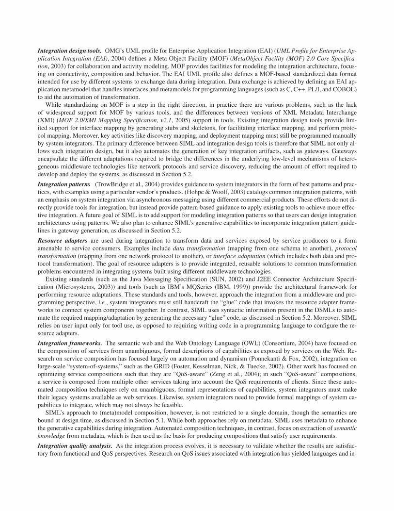
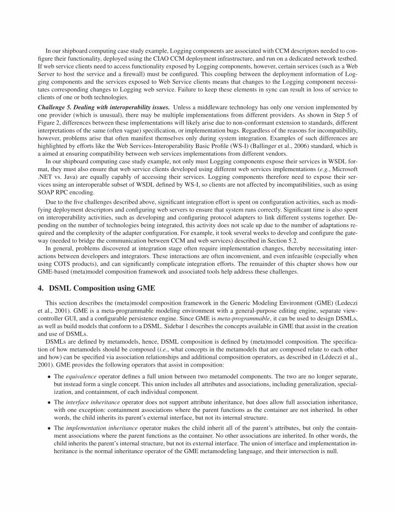
Figure 1. Enterprise Distributed System Architecture
frastructure for evaluating service-level agreements, which are contracts between service providers and consumers that definethe obligations of the parties involved and specify what measures to take if service assurances are not satisfied. Examples in-clude (1) the Web Service-Level Agreement language (WSLA) (Ludwig, Keller, Dan, King, & Franck, 2003) framework,which defines an architecture to define service-level agreements using an XML Schema, and provides an infrastructure tomonitor the conformance of the running system to the desired service-level agreement, (2) (Oldham, Verma, Sheth, & Hakim-pour, 2006), which allows monitoring user-specific service level agreements within the WS-Agreement framework, and (3)Rule-Based Service Level Agreement (Paschke, Dietrich, & Kuhla, 2005), which is a formal multi-layer approach to describ-ing and monitoring service level agreements. Other efforts have focused on defining processes for distributed continuousquality assurance (Wang & Gill, 2004) of integrated systems to identify the impact on performance during system evolu-tion. Information from these analysis tools should be incorporated into future integration activities.
Although quality analysis tools can provide input to design-time integration activities, they do not support automated feed-back loops. In particular, they do not provide mechanisms to modify the integration design based on results of quality analy-sis. SIML, in contrast, is designed to model service-level agreements to allow their evaluation before and/or after integration,as discussed in Section 5.1.
3. Functional Integration Case Study
To motivate the need for MDE-based functional integration capabilities, this section describes an enterprise distributedsystem case study from the domain of shipboard computing environments (Hill et al., 2006), focusing on its functional inte-gration challenges. A shipboard computing environment is a metropolitan area network (MAN) of computational resourcesand sensors that provides on-demand situational awareness and actuation capabilities for human operators, and responds flex-ibly to unanticipated runtime conditions. To meet such demands in a robust and timely manner, the shipboard computing en-vironment uses services to
• Bridge the gap between shipboard applications and the underlying operating systems and middleware infrastructureand
• Support multiple QoS requirements, such as survivability, predictability, security, and efficient resource utilization.
The shipboard computing environment that forms the basis for our case study was originally developed using one componentmiddleware technology: OMG CCM implemented using the CIAO middleware (Institute for Software Integrated Systems,Vanderbilt University). It was later enhanced to integrate with components written using another middleware technology:W3C web services implemented using Microsoft’s .NET web services.
3.1. Shipboard Enterprise Distributed System Architecture
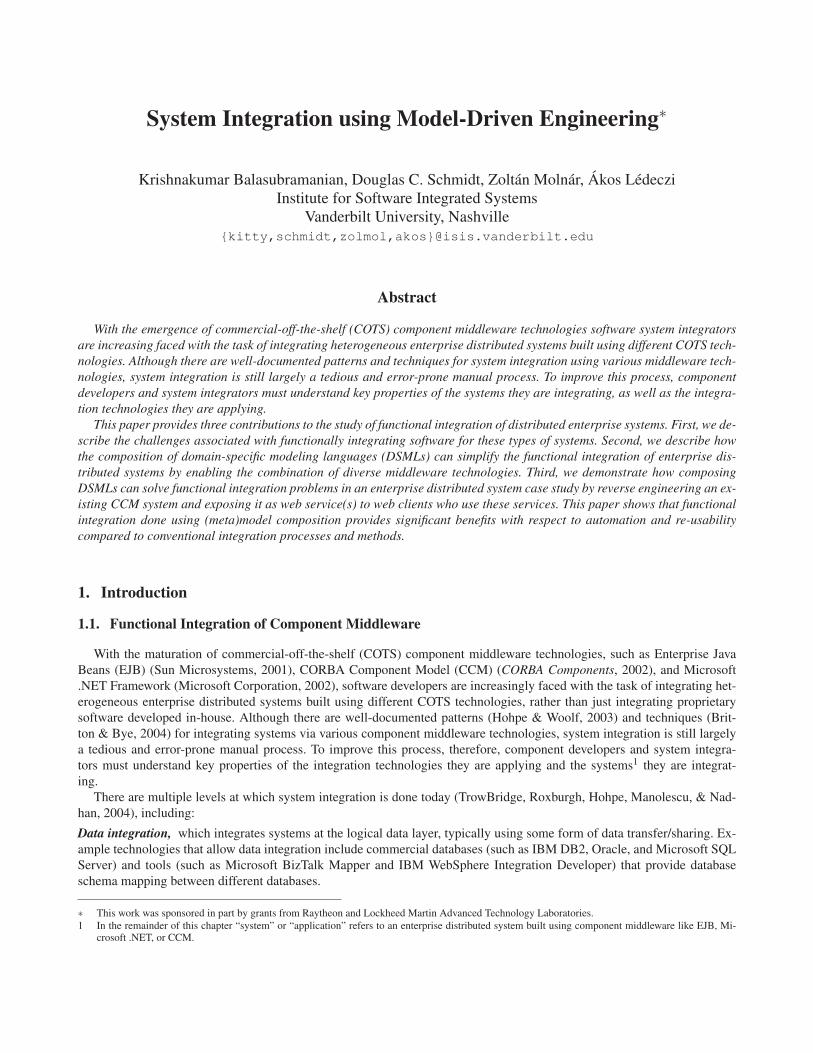
The enterprise distributed system in our case study consists of the components shown in Figure 1 and outlined below:
• Gateway component, which provides the user interface and main point of entry into the system for operators,
• Naming Service components, which are repositories that hold locations of services available within the system,
• Identity Manager components, which are responsible for user authentication and authorization,
• Business logic components, which are responsible for implementing business logic, such as determining the route tobe taken as part of ship navigation, tracking the work allocation schedule for sailors, etc.,
• Database components, which are responsible for database transactions,
• Coordinator components, which act as proxies for business logic components and interact with clients,
• Logging components, which are responsible for collecting log messages sent by other components,
• Log Analyzer components, which analyze logs collected by Logging components and display results.
Clients that use the component services outlined above first connect to a Naming Service to obtain the Gateway’s loca-tion. They then request services offered by the system, passing their authentication/authorization credentials to a Gatewaycomponent, which initiates the series of interactions shown in Figure 1. The system provides differentiated services depend-ing on the credentials supplied by clients. Areas where services can be differentiated between various clients include themaximum number of simultaneous connections, maximum amount of bandwidth allocated, and maximum number of re-quests processed in a particular time period.
To track the performance of the system—and the QoS the system offers to different clients—application developers orig-inally wrote Log Analyzer components to obtain information by analyzing the logs. Based on changes in the COTS technol-ogy base and user requirements, a decision was made to expose a web service API to Logging components so that clientscould also track the QoS provided by the system to their requests by accessing information available in Logging compo-nents. Since the original system was written using CCM, this change request introduced a new requirement to integrate sys-tems that were not designed to work together, i.e., CCM-based Logging components with the Web Service clients.
The flow of control—and the number and functionality of the different participants—in this case study is representative ofenterprise distributed systems that require authentication and authorization from clients—and provide differentiated servicesto clients—based on the credentials offered by the client. Below, we examine this system from an integration perspective, i.e.,how can this system—which initially had a homogeneous, stand-alone design—be integrated with other middleware. Notethat this chapter is not studying the system from the perspective of system functionality or the QoS provided by the BusinessLogic components.
3.2. Functional Integration Challenges
Functional integration of systems is hard and involves activities that map between various levels of abstraction in the in-tegration lifecycle, including design, implementation, and use of tools. Below we describe some of the key challenges as-sociated with integrating older component middleware technologies, such as CCM and EJB, with newer middleware tech-nologies, such as web services, and relate them to our experiences developing the shipboard computing case study describedin Section 3.1. The following list of challenges is by no means complete, i.e., we focus on challenges addressed by our ap-proach.
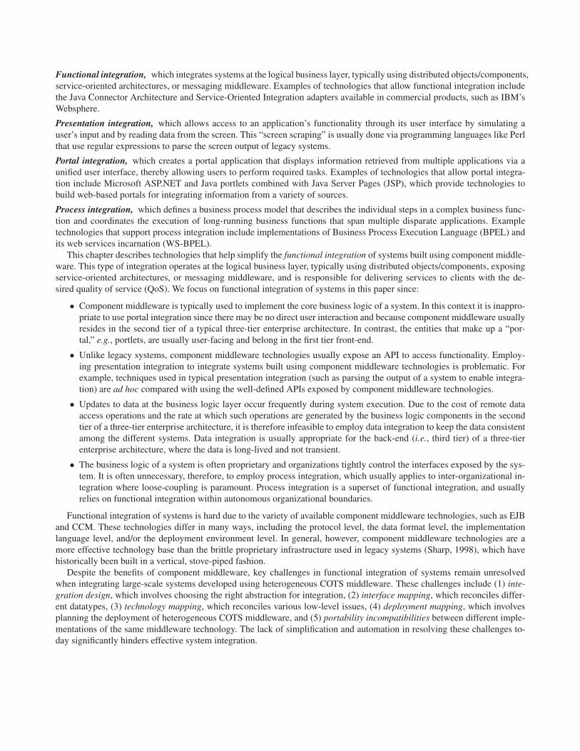
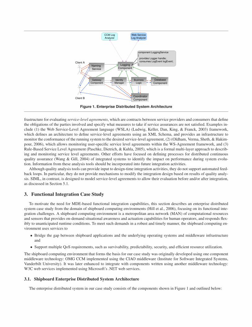
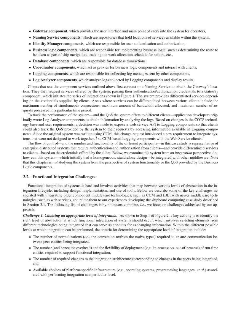
Challenge 1. Choosing an appropriate level of integration. As shown in Step 1 of Figure 2, a key activity is to identify theright level of abstraction at which functional integration of systems should occur, which involves selecting elements fromdifferent technologies being integrated that can serve as conduits for exchanging information. Within the different possiblelevels at which integration can be performed, the criteria for determining the appropriate level of integration include:
• The number of normalizations (i.e., the conversion to/from the native types) required to ensure communication be-tween peer entities being integrated,
• The number (and hence the overhead) and the flexibility of deployment (e.g., in-process vs. out-of-process) of run-timeentities required to support functional integration,
• The number of required changes to the integration architecture corresponding to changes in the peers being integrated,and
• Available choices of platform-specific infrastructure (e.g., operating systems, programming languages, et al.) associ-ated with performing integration at a particular level.
Web Services
CORBA Component Model
Web Service
Deployment
descriptors
1
2
3
4
5
Gateway
Identity
Manager
Business
Logic
Naming
Service
Coordinator
Database
Logging Logging
Java Log
Analyzer
C# Log
Analyzer
Log
Analyzer
CCM Deployment
descriptors
component Benchmark_Data_Collector
{
provides Testing_Service testing_service;
provides BDC_Control_Handle controls;
attribute long timeout;
attribute string service;
};
<wsdl:service
name="CUTS.Benchmark_Data_Collector">
<wsdl:port
name="CUTS.Benchmark_Data_Collector.controls"
binding="tns:CUTS.Benchmark_Data_Collector._SE_
controls">
<soap:address location="http://localhost:8080/"
wsdl:required="false"/>
</wsdl:port>
</wsdl:service>
TypeSpecific
IIOP SOAP
CCM ComponentWeb ServiceWeb Service Client
Figure 2. Functional Integration Challenges
Attempting integration at the wrong level of abstraction can yield brittle integration architectures. For instance, the por-tions of the system implementing the integration might require frequent changes in response to changes in either the sourceor the target system being integrated.
In our shipboard computing case study example, we need to integrate Logging components so that web service clientscan access their services. The programming model of CCM prescribes component ports as the primary component inter-connection mechanism. Web Services also defines ports as the primary interconnection mechanism between a web serviceand its clients. During functional integration of CCM with web services, therefore, a mapping between CCM componentports and web services ports offers an appropriate level of abstraction for integration. Although mapping CCM and web ser-vices ports is relatively straightforward, determining the right level of abstraction to integrate arbitrary middleware technolo-gies can be much harder since a natural mapping between technologies may not always exist. In general, it is hard for systemintegrators to decide the right level of abstraction, and requires expertise in all the technologies being integrated.
Challenge 2. Reconciling differences in interface specifications. After the level of abstraction to perform functional inte-gration is determined, it is necessary to map the interfaces exposed by elements of the different technologies as shown inStep 2 of Figure 2. COTS middleware technologies usually have an interface definition mechanism that is separate from thecomponent/service implementation details, e.g., CCM uses the OMG Interface Definition Language (IDL), whereas web ser-vices use W3C Web Services Definition Language (WSDL). Older technologies (such as COBOL or C) may not offer as cleara separation of interfaces from implementations, so the interface definition itself may be tangled. Irrespective of the mecha-nism used to define interfaces, mapping interfaces between any two technologies involves at least three tasks:
• Datatype mapping, which involves mapping a datatype (both pre-defined and complex types) from source to targettechnology.
• Exception mapping, which involves mapping exceptions from source to target technology. Exceptions are defined sep-arately from datatypes since the source or target technologies may not support (e.g., Microsoft’s COM uses a HRE-
SULT to convey errors instead of using native C++ exceptions).
• Language mapping, which involves mapping datatypes between two technologies while accounting for differencesin languages at the same time. Functional integration is limited when attempting this mapping, which is often done
via inter-process communication at runtime to work around limitations in hosting these technologies “in-process”, i.e.,within the same process.
In our shipboard computing case study example, Logging components handle CORBA datatypes, (which offer a lim-ited subset of datatypes) whereas web service clients exchange XML datatypes (which provide a virtually unlimited set ofdatatypes due to XML’s flexibility). Similarly, Logging components throw CORBA exceptions with specific minor/majorcodes containing specific fault and retry semantics. In contrast, web service clients must convert these exceptions to SOAP“faults,” which have a smaller set of exception codes and associated fault semantics. Performing these mappings is non-trivial, requires expertise in both the source and target technologies, and can incur scalability problems due to tedium anderror-proneness if not automated.
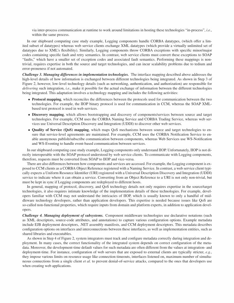
Challenge 3. Managing differences in implementation technologies. The interface mapping described above addresses thehigh-level details of how information is exchanged between different technologies being integrated. As shown in Step 3 ofFigure 2, however, low-level technology details (such as networking, authentication, and authorization) are responsible fordelivering such integration, i.e., make it possible for the actual exchange of information between the different technologiesbeing integrated. This adaptation involves a technology mapping and includes the following activities:
• Protocol mapping, which reconciles the differences between the protocols used for communication between the twotechnologies. For example, the IIOP binary protocol is used for communication in CCM, whereas the SOAP XML-based text protocol is used in web services.
• Discovery mapping, which allows bootstrapping and discovery of components/services between source and targettechnologies. For example, CCM uses the CORBA Naming Service and CORBA Trading Service, whereas web ser-vices use Universal Description Discovery and Integration (UDDI) to discover other web services.
• Quality of Service (QoS) mapping, which maps QoS mechanisms between source and target technologies to en-sure that service-level agreements are maintained. For example, CCM uses the CORBA Notification Service to en-able anonymous publish/subscribe communication between components, whereas Web Services use WS-Notificationand WS-Eventing to handle event-based communication between services.
In our shipboard computing case study example, Logging components only understand IIOP. Unfortunately, IIOP is not di-rectly interoperable with the SOAP protocol understood by web service clients. To communicate with Logging components,therefore, requests must be converted from SOAP to IIOP and vice-versa.
There are also differences between how components and services are accessed. For example, the Logging component is ex-posed to CCM clients as a CORBA Object Reference registered with a Naming Service. In contrast, a web service client typi-cally expects a Uniform Resource Identifier (URI) registered with a Universal Description Discovery and Integration (UDDI)service to indicate where it can obtain a service. Converting from an Object Reference to a URI is not only non-trivial, butmust be kept in sync if Logging components are redeployed to different hosts.
In general, mapping of protocol, discovery, and QoS technology details not only requires expertise in the source/targettechnologies, it also requires intimate knowledge of the implementation details of these technologies. For example, devel-opers familiar with CCM may not understand the intricacies of IIOP, which is usually known to only a handful of mid-dleware technology developers, rather than application developers. This expertise is needed because issues like QoS areso-called non-functional properties, which require inputs from domain and platform experts, in addition to application devel-opers.
Challenge 4. Managing deployment of subsystems. Component middleware technologies use declarative notations (suchas XML descriptors, source-code attributes, and annotations) to capture various configuration options. Example metadatainclude EJB deployment descriptors, .NET assembly manifests, and CCM deployment descriptors. This metadata describesconfiguration options on interfaces and interconnections between these interfaces, as well as implementation entities, such asshared libraries and executables.
As shown in Step 4 of Figure 2, system integrators must track and configure metadata correctly during integration and de-ployment. In many cases, the correct functionality of the integrated system depends on correct configuration of the meta-data. Moreover, the development-time default values for such metadata are often different from the values at integration- anddeployment-time. For instance, configuration of web servers that are exposed to external clients are typically stricter, e.g.,they impose various limits on resource usage like connection timeouts, interfaces listened on, maximum number of simulta-neous connections from a single client et al. to prevent denial-of-service attacks, compared to the ones that developers usewhen creating web applications.
In our shipboard computing case study example, Logging components are associated with CCM descriptors needed to con-figure their functionality, deployed using the CIAO CCM deployment infrastructure, and run on a dedicated network testbed.If web service clients need to access functionality exposed by Logging components, however, certain services (such as a WebServer to host the service and a firewall) must be configured. This coupling between the deployment information of Log-ging components and the services exposed to Web Service clients means that changes to the Logging component necessi-tates corresponding changes to Logging web service. Failure to keep these elements in sync can result in loss of service toclients of one or both technologies.
Challenge 5. Dealing with interoperability issues. Unless a middleware technology has only one version implemented byone provider (which is unusual), there may be multiple implementations from different providers. As shown in Step 5 ofFigure 2, differences between these implementations will likely arise due to non-conformant extension to standards, differentinterpretations of the same (often vague) specification, or implementation bugs. Regardless of the reasons for incompatibility,however, problems arise that often manifest themselves only during system integration. Examples of such differences arehighlighted by efforts like the Web Services-Interoperability Basic Profile (WS-I) (Ballinger et al., 2006) standard, which isa aimed at ensuring compatibility between web services implementations from different vendors.
In our shipboard computing case study example, not only must Logging components expose their services in WSDL for-mat, they must also ensure that web service clients developed using different web services implementations (e.g., Microsoft.NET vs. Java) are equally capably of accessing their services. Logging components therefore need to expose their ser-vices using an interoperable subset of WSDL defined by WS-I, so clients are not affected by incompatibilities, such as usingSOAP RPC encoding.
Due to the five challenges described above, significant integration effort is spent on configuration activities, such as modi-fying deployment descriptors and configuring web servers to ensure that system runs correctly. Significant time is also spenton interoperability activities, such as developing and configuring protocol adapters to link different systems together. De-pending on the number of technologies being integrated, this activity does not scale up due to the number of adaptations re-quired and the complexity of the adapter configuration. For example, it took several weeks to develop and configure the gate-way (needed to bridge the communication between CCM and web services) described in Section 5.2.
In general, problems discovered at integration stage often require implementation changes, thereby necessitating inter-actions between developers and integrators. These interactions are often inconvenient, and even infeasible (especially whenusing COTS products), and can significantly complicate integration efforts. The remainder of this chapter shows how ourGME-based (meta)model composition framework and associated tools help address these challenges.
4. DSML Composition using GME
This section describes the (meta)model composition framework in the Generic Modeling Environment (GME) (Ledecziet al., 2001). GME is a meta-programmable modeling environment with a general-purpose editing engine, separate view-controller GUI, and a configurable persistence engine. Since GME is meta-programmable, it can be used to design DSMLs,as well as build models that conform to a DSML. Sidebar 1 describes the concepts available in GME that assist in the creationand use of DSMLs.
DSMLs are defined by metamodels, hence, DSML composition is defined by (meta)model composition. The specifica-tion of how metamodels should be composed (i.e., what concepts in the metamodels that are composed relate to each otherand how) can be specified via association relationships and additional composition operators, as described in (Lédeczi et al.,2001). GME provides the following operators that assist in composition:
• The equivalence operator defines a full union between two metamodel components. The two are no longer separate,but instead form a single concept. This union includes all attributes and associations, including generalization, special-ization, and containment, of each individual component.
• The interface inheritance operator does not support attribute inheritance, but does allow full association inheritance,with one exception: containment associations where the parent functions as the container are not inherited. In otherwords, the child inherits its parent’s external interface, but not its internal structure.
• The implementation inheritance operator makes the child inherit all of the parent’s attributes, but only the contain-ment associations where the parent functions as the container. No other associations are inherited. In other words, thechild inherits the parent’s internal structure, but not its external interface. The union of interface and implementation in-heritance is the normal inheritance operator of the GME metamodeling language, and their intersection is null.
Sidebar 1: Generic Modeling Environment
The Generic Modeling Environment (GME) is an open-source, visual, configurable design environment for creat-ing DSMLs and program synthesis environments, available for download from escher.isis.vanderbilt.edu/
downloads?tool=GME. A unique feature of GME is that it is meta-programmable, which means that it can not onlybuild DSMLs, but also build models that conform to a DSML. In fact, the environment used to build DSMLs in GME is it-self built using another DSML (also known as the meta-metamodel) called “MetaGME,” which provides the following ele-ments to define a DSML:
• Project, which is the top-level container in a DSML,• Folders, which are used to group collections of similar elements together,• Atoms, which are the indivisible elements of a DSML, and used to represent the leaf-level elements in a DSML,• Models, which are the compound objects in a DSML, and are used to contain different types of elements like Refer-
ences, Sets, Atoms, Connections et al. (the elements that are contained by a Model are known as parts),• Aspects, which are used to provide a different viewpoint of the same Model (every part of a Model is associated with
an Aspect),• Connections, which are used to represent relationships between the elements of the domain,• References, which are used to refer to other elements in different portions of a DSML hierarchy (unlike Connections,
which can be used to connect elements within a Model),• Sets, which are containers whose elements are defined within the same aspect and have the same container as the
owner.
Together, these three operators allow for a semantically rich composition of metamodels.A key property of a composite DSML is that it supports the open-closed principle (Meyer, 1992), which states that a class
should be open for extension but closed with respect to its public interface. In GME, elements of the sub-DSMLs are closed,i.e., their semantics cannot be altered in the composite DSML. The composite DSML itself, however, is open, i.e., it al-lows the definition of new interactions and the creation of new derived elements. All tools that are built for each sub-DSMLwork without any modifications in the composite DSML and all the models built in the sub-DSMLs are also usable in thecomposite DSML.
We use the following GME (meta)model composition features to support the SIML-based integration of systems builtusing different middleware technologies, as described in Section 5:
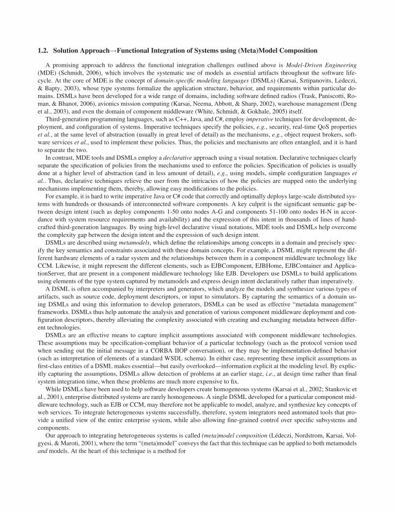
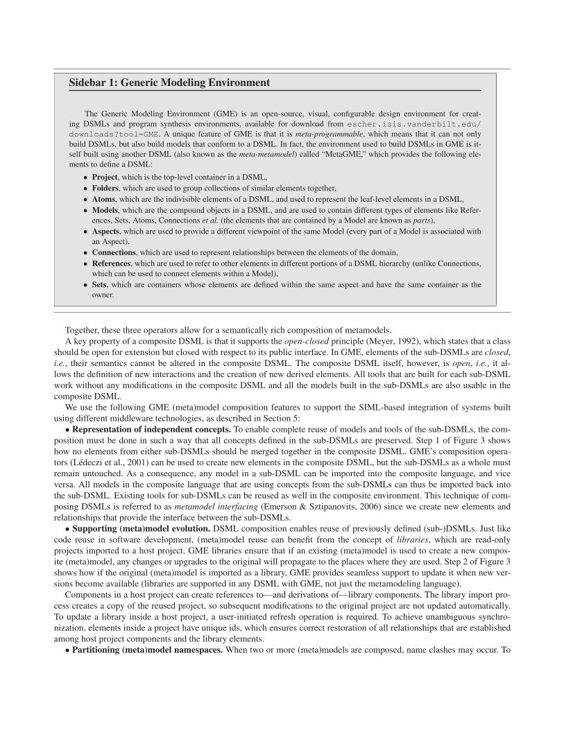
• Representation of independent concepts. To enable complete reuse of models and tools of the sub-DSMLs, the com-position must be done in such a way that all concepts defined in the sub-DSMLs are preserved. Step 1 of Figure 3 showshow no elements from either sub-DSMLs should be merged together in the composite DSML. GME’s composition opera-tors (Lédeczi et al., 2001) can be used to create new elements in the composite DSML, but the sub-DSMLs as a whole mustremain untouched. As a consequence, any model in a sub-DSML can be imported into the composite language, and viceversa. All models in the composite language that are using concepts from the sub-DSMLs can thus be imported back intothe sub-DSML. Existing tools for sub-DSMLs can be reused as well in the composite environment. This technique of com-posing DSMLs is referred to as metamodel interfacing (Emerson & Sztipanovits, 2006) since we create new elements andrelationships that provide the interface between the sub-DSMLs.
• Supporting (meta)model evolution. DSML composition enables reuse of previously defined (sub-)DSMLs. Just likecode reuse in software development, (meta)model reuse can benefit from the concept of libraries, which are read-onlyprojects imported to a host project. GME libraries ensure that if an existing (meta)model is used to create a new compos-ite (meta)model, any changes or upgrades to the original will propagate to the places where they are used. Step 2 of Figure 3shows how if the original (meta)model is imported as a library, GME provides seamless support to update it when new ver-sions become available (libraries are supported in any DSML with GME, not just the metamodeling language).
Components in a host project can create references to—and derivations of—library components. The library import pro-cess creates a copy of the reused project, so subsequent modifications to the original project are not updated automatically.To update a library inside a host project, a user-initiated refresh operation is required. To achieve unambiguous synchro-nization, elements inside a project have unique ids, which ensures correct restoration of all relationships that are establishedamong host project components and the library elements.
• Partitioning (meta)model namespaces. When two or more (meta)models are composed, name clashes may occur. To
System Integration Modeling
Language
PICML WSML
Component
Port
Service
BindingPort
HttpsBinding
Service
BindingPort
Figure 3. Domain-Specific Modeling Language Composition in GME
alleviate this problem, (meta)model libraries (and hence the corresponding components DSMLs) can have their own names-paces specified by (meta)modelers, as shown in Step 3 of Figure 3. External software components, such as code genera-tors or model analysis tools that were developed for the composite DSML, must use the fully qualified names. But tools thatwere developed for component DSMLs will still work because GME sets the context correctly before invoking such a com-ponent.
• Handling constraints. The syntactic definitions of a metamodel in GME can be augmented by static semantics specifi-cations in the form of Object Constraint Language (OCL) (Warmer & Kleppe, 2003) constraint expressions. When metamod-els are composed together, the predefined OCL expressions coming from a sub-DSML should not be altered. GME’s Con-straint Manager therefore uses namespace specifications to avoid any possible ambiguities, and these expressions are eval-uated by the Constraint Manager with the correct types and priorities as defined by the sub-DSML, as shown in Step 4 ofFigure 3. The composite DSML can also define new OCL expressions to specify the static semantics that augment the speci-fications originating in the metamodels of the sub-DSMLs.
5. Integrating Systems with SIML
This section describes how we created and applied the System Integration Modeling Language (SIML) to solve the chal-lenges associated with functional integration of systems in the context of the shipboard computing scenario described in Sec-tion 3.1. SIML is our open-source composite DSML that simplifies functional integration of component-based systems builtusing heterogeneous middleware technologies. First, we describe how SIML applies GME’s (meta)model composition fea-tures described in Section 4 to compose DSMLs built for CCM and web services. We then describe how the challenges de-scribed in Section 3.2 are resolved using features in SIML.
5.1. The Design and Functionality of SIML
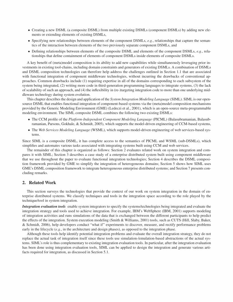
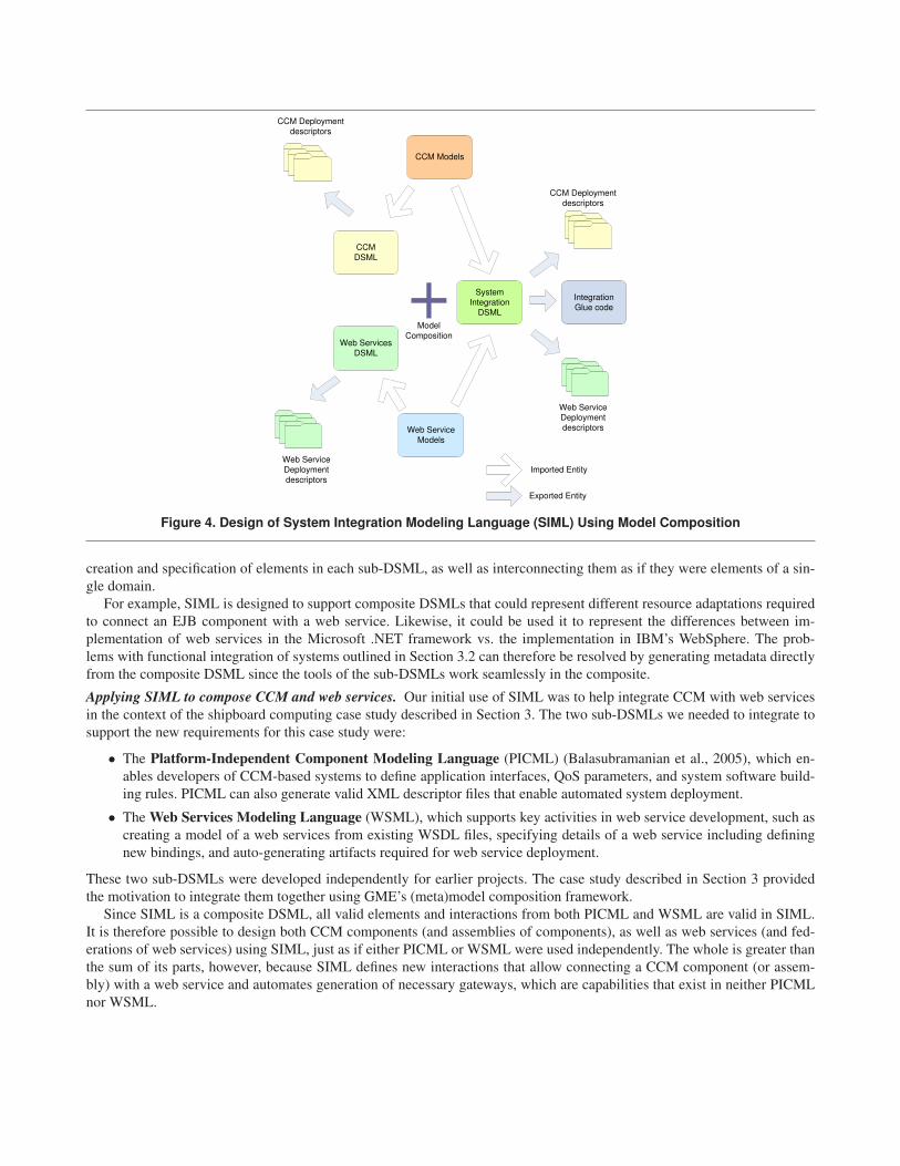
Applying GME’s (meta)model composition features to SIML. To support integration of systems built using different mid-dleware technologies, SIML uses the GME (meta)model composition features described in Section 4 as shown in Figure 4.SIML is thus a composite DSML that allows integration of systems by composing multiple DSMLs, each representing a dif-ferent middleware technology. Each sub-DSML is responsible for managing the metadata (creation, as well as generation) ofthe middleware technology it represents.
The composite DSML produced using SIML defines the semantics of the integration, which might include reconciling dif-ferences between the diverse technologies, as well as representing characteristics of various implementations. The result is asingle composite DSML that retains all the characteristics of its sub-DSMLs, yet also unifies them by defining new interac-tions between elements present in both DSMLs. System integrators therefore have a single MDE environment that allows the
CCM
DSML
Web Services DSML
CCM Models
Web Service
Models
System
IntegrationDSML
Model
Composition
CCM Deployment
descriptors
Web Service
Deployment
descriptors
CCM Deployment
descriptors
Web Service
Deployment
descriptors
Integration
Glue code
Imported Entity
Exported Entity
Figure 4. Design of System Integration Modeling Language (SIML) Using Model Composition
creation and specification of elements in each sub-DSML, as well as interconnecting them as if they were elements of a sin-gle domain.
For example, SIML is designed to support composite DSMLs that could represent different resource adaptations requiredto connect an EJB component with a web service. Likewise, it could be used it to represent the differences between im-plementation of web services in the Microsoft .NET framework vs. the implementation in IBM’s WebSphere. The prob-lems with functional integration of systems outlined in Section 3.2 can therefore be resolved by generating metadata directlyfrom the composite DSML since the tools of the sub-DSMLs work seamlessly in the composite.
Applying SIML to compose CCM and web services. Our initial use of SIML was to help integrate CCM with web servicesin the context of the shipboard computing case study described in Section 3. The two sub-DSMLs we needed to integrate tosupport the new requirements for this case study were:
• The Platform-Independent Component Modeling Language (PICML) (Balasubramanian et al., 2005), which en-ables developers of CCM-based systems to define application interfaces, QoS parameters, and system software build-ing rules. PICML can also generate valid XML descriptor files that enable automated system deployment.
• The Web Services Modeling Language (WSML), which supports key activities in web service development, such ascreating a model of a web services from existing WSDL files, specifying details of a web service including definingnew bindings, and auto-generating artifacts required for web service deployment.
These two sub-DSMLs were developed independently for earlier projects. The case study described in Section 3 providedthe motivation to integrate them together using GME’s (meta)model composition framework.
Since SIML is a composite DSML, all valid elements and interactions from both PICML and WSML are valid in SIML.It is therefore possible to design both CCM components (and assemblies of components), as well as web services (and fed-erations of web services) using SIML, just as if either PICML or WSML were used independently. The whole is greater thanthe sum of its parts, however, because SIML defines new interactions that allow connecting a CCM component (or assem-bly) with a web service and automates generation of necessary gateways, which are capabilities that exist in neither PICMLnor WSML.
System Integration Modeling Language
Web Services Modeling Language
Platform-Independent Component Modeling Language
Web Service
Deployment
descriptors
CCM Component
Gateway
Identity
Manager
Business
Logic
Naming
Service
Coordinator
Database
Logging Logging
Java Log
Analyzer
C# Log
Analyzer
Log
Analyzer
CCM Deployment
descriptors
Interface Definition
Language Files
Web Services Definition
Language Files
idl_to_picml.exe
idl_to_wsdl.exe
WSDLImporter.exe
WSDLExporter.exe
DeploymentPlan.exe
GatewayGenerator.exe
Web ServiceWeb Service Client
12
3
4
57
6TypeSpecific
Gateway
IIOP SOAP
SOAP
Server
CCM
Client
Figure 5. Generating a Web Service Gateway Using SIML
5.2. Resolving Functional Integration Challenges using SIML
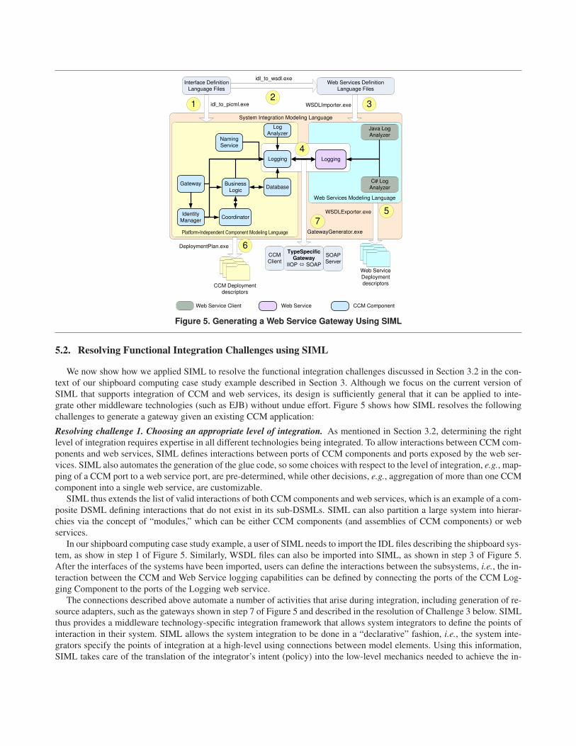
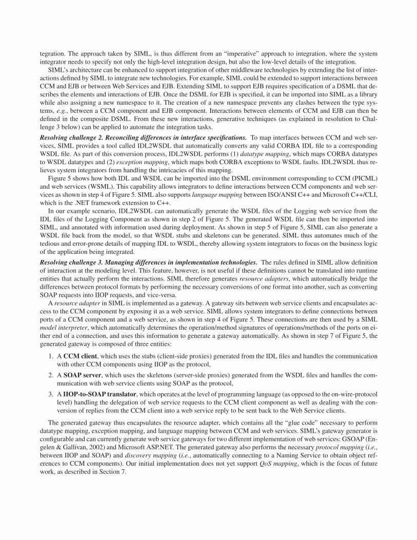
We now show how we applied SIML to resolve the functional integration challenges discussed in Section 3.2 in the con-text of our shipboard computing case study example described in Section 3. Although we focus on the current version ofSIML that supports integration of CCM and web services, its design is sufficiently general that it can be applied to inte-grate other middleware technologies (such as EJB) without undue effort. Figure 5 shows how SIML resolves the followingchallenges to generate a gateway given an existing CCM application:
Resolving challenge 1. Choosing an appropriate level of integration. As mentioned in Section 3.2, determining the rightlevel of integration requires expertise in all different technologies being integrated. To allow interactions between CCM com-ponents and web services, SIML defines interactions between ports of CCM components and ports exposed by the web ser-vices. SIML also automates the generation of the glue code, so some choices with respect to the level of integration, e.g., map-ping of a CCM port to a web service port, are pre-determined, while other decisions, e.g., aggregation of more than one CCMcomponent into a single web service, are customizable.
SIML thus extends the list of valid interactions of both CCM components and web services, which is an example of a com-posite DSML defining interactions that do not exist in its sub-DSMLs. SIML can also partition a large system into hierar-chies via the concept of “modules,” which can be either CCM components (and assemblies of CCM components) or webservices.
In our shipboard computing case study example, a user of SIML needs to import the IDL files describing the shipboard sys-tem, as show in step 1 of Figure 5. Similarly, WSDL files can also be imported into SIML, as shown in step 3 of Figure 5.After the interfaces of the systems have been imported, users can define the interactions between the subsystems, i.e., the in-teraction between the CCM and Web Service logging capabilities can be defined by connecting the ports of the CCM Log-ging Component to the ports of the Logging web service.
The connections described above automate a number of activities that arise during integration, including generation of re-source adapters, such as the gateways shown in step 7 of Figure 5 and described in the resolution of Challenge 3 below. SIMLthus provides a middleware technology-specific integration framework that allows system integrators to define the points ofinteraction in their system. SIML allows the system integration to be done in a “declarative” fashion, i.e., the system inte-grators specify the points of integration at a high-level using connections between model elements. Using this information,SIML takes care of the translation of the integrator’s intent (policy) into the low-level mechanics needed to achieve the in-
tegration. The approach taken by SIML, is thus different from an “imperative” approach to integration, where the systemintegrator needs to specify not only the high-level integration design, but also the low-level details of the integration.
SIML’s architecture can be enhanced to support integration of other middleware technologies by extending the list of inter-actions defined by SIML to integrate new technologies. For example, SIML could be extended to support interactions betweenCCM and EJB or between Web Services and EJB. Extending SIML to support EJB requires specification of a DSML that de-scribes the elements and interactions of EJB. Once the DSML for EJB is specified, it can be imported into SIML as a librarywhile also assigning a new namespace to it. The creation of a new namespace prevents any clashes between the type sys-tems, e.g., between a CCM component and EJB component. Interactions between elements of CCM and EJB can then bedefined in the composite DSML. From these new interactions, generative techniques (as explained in resolution to Chal-lenge 3 below) can be applied to automate the integration tasks.
Resolving challenge 2. Reconciling differences in interface specifications. To map interfaces between CCM and web ser-vices, SIML provides a tool called IDL2WSDL that automatically converts any valid CORBA IDL file to a correspondingWSDL file. As part of this conversion process, IDL2WSDL performs (1) datatype mapping, which maps CORBA datatypesto WSDL datatypes and (2) exception mapping, which maps both CORBA exceptions to WSDL faults. IDL2WSDL thus re-lieves system integrators from handling the intricacies of this mapping.
Figure 5 shows how both IDL and WSDL can be imported into the DSML environment corresponding to CCM (PICML)and web services (WSML). This capability allows integrators to define interactions between CCM components and web ser-vices as shown in step 4 of Figure 5. SIML also supports language mapping between ISO/ANSI C++ and Microsoft C++/CLI,which is the .NET framework extension to C++.
In our example scenario, IDL2WSDL can automatically generate the WSDL files of the Logging web service from theIDL files of the Logging Component as shown in step 2 of Figure 5. The generated WSDL file can then be imported intoSIML, and annotated with information used during deployment. As shown in step 5 of Figure 5, SIML can also generate aWSDL file back from the model, so that WSDL stubs and skeletons can be generated. SIML thus automates much of thetedious and error-prone details of mapping IDL to WSDL, thereby allowing system integrators to focus on the business logicof the application being integrated.
Resolving challenge 3. Managing differences in implementation technologies. The rules defined in SIML allow definitionof interaction at the modeling level. This feature, however, is not useful if these definitions cannot be translated into runtimeentities that actually perform the interactions. SIML therefore generates resource adapters, which automatically bridge thedifferences between protocol formats by performing the necessary conversions of one format into another, such as convertingSOAP requests into IIOP requests, and vice-versa.
A resource adapter in SIML is implemented as a gateway. A gateway sits between web service clients and encapsulates ac-cess to the CCM component by exposing it as a web service. SIML allows system integrators to define connections betweenports of a CCM component and a web service, as shown in step 4 of Figure 5. These connections are then used by a SIMLmodel interpreter, which automatically determines the operation/method signatures of operations/methods of the ports on ei-ther end of a connection, and uses this information to generate a gateway automatically. As shown in step 7 of Figure 5, thegenerated gateway is composed of three entities:
1. A CCM client, which uses the stubs (client-side proxies) generated from the IDL files and handles the communicationwith other CCM components using IIOP as the protocol,
2. A SOAP server, which uses the skeletons (server-side proxies) generated from the WSDL files and handles the com-munication with web service clients using SOAP as the protocol,
3. A IIOP-to-SOAP translator, which operates at the level of programming language (as opposed to the on-wire-protocollevel) handling the delegation of web service requests to the CCM client component as well as dealing with the con-version of replies from the CCM client into a web service reply to be sent back to the Web Service clients.
The generated gateway thus encapsulates the resource adapter, which contains all the “glue code” necessary to performdatatype mapping, exception mapping, and language mapping between CCM and web services. SIML’s gateway generator isconfigurable and can currently generate web service gateways for two different implementation of web services: GSOAP (En-gelen & Gallivan, 2002) and Microsoft ASP.NET. The generated gateway also performs the necessary protocol mapping (i.e.,between IIOP and SOAP) and discovery mapping (i.e., automatically connecting to a Naming Service to obtain object ref-erences to CCM components). Our initial implementation does not yet support QoS mapping, which is the focus of futurework, as described in Section 7.
In our shipboard computing case study example, SIML can automatically generate the Logging web service gateway con-forming to GSOAP and/or Microsoft ASP.NET, by running the SIML model interpreter as shown in step 7 of Figure 5.Auto-generation of gateways eliminates the tedious and error-prone programming effort that would have otherwise been re-quired to integrate CCM components with Web Services. In general, given a pair of technologies to integrate, auto-generationof gateways eliminates the need for both writing code required to perform the technology mapping, as well as the repetitive in-stantiation of such code for each of the interfaces that need to be integrated. Auto-generation also masks the details of theconfiguration of the technology-specific resource adapters used in the integration.
Resolving challenge 4. Managing deployment of subsystems. After the necessary integration gateways have been gener-ated, system integrators also need to deploy and configure the application and the middleware using metadata, e.g., in theform of XML descriptors. Since SIML is built using (meta)model composition it can automatically use the tools devel-oped for the sub-DSMLs directly from within SIML. For instance, PICML can handle deployment of CCM applications andWSML can handle deployment of web services.
In our shipboard computing case study example, SIML can thus be used to automatically generate the necessary de-ployment descriptors for all CCM components, as well as the Logging web service as shown in steps 5 and 6 of Figure 5.SIML therefore shields system integrators from low-level details of the formats of the different descriptors. It also shieldsthem from manually keeping track of the number of such descriptors required to deploy a CCM component or a Web Ser-vice.
By encapsulating the required resource adapters inside a web service or CCM component, SIML allows reuse of deploy-ment techniques available for both CCM and web services. System integrators therefore need not deploy resource adaptersseparately. While this approach works for in-process resource adapters (such as those generated by SIML), out-of-process re-source adapters need support from a deployment descriptor generator. Since SIML is a DSML itself, this support could beadded to SIML so it can generate deployment support for out-of-process resource adapters.
Resolving challenge 5. Dealing with interoperability issues. Since knowledge of the underlying middleware technologiesis built into SIML, it can compensate for certain types of incompatibilities, such as differences in interface definition stylesduring design time. For example, IDL2WSDL allows generation of WSDL that supports an interoperable subset of WSDLas defined in the WS-I Basic Profile. System integrators are thus better prepared to avoid incompatibilities that would havetraditionally arisen during integration testing.
SIML can also define constraints on WSDL definition as prescribed by the WS-I Basic Profile, so that violations can alsobe checked at modeling time. Similarly, gateway generation can automatically add workarounds for particular implementa-tion quirks, such as defining the correct set of values for XML namespaces of the interfaces defined in WSDL files dependingupon the (observed) behavior of the target middleware implementation. System integrators are once again shielded from dis-covering these problems during final integration testing. In our shipboard computing case study example, SIML can generatea Logging web service gateway that either supports a WS-I subset or uses SOAP RPC encoding.
SIML’s DSML composition-based approach to integrating systems therefore relieves system integrators from developingmore code during integration. The automation of gateway generation allows integration of systems that have a large numberof components since developers need not write system specific integration code. In addition, SIML supports evolution of theintegrated system by incrementally adding more components or by targeting different middleware implementations as futureneeds dictate.
6. Future Trends
This section discusses emerging and future technological trends in the integration of systems, with special focus on func-tional integration and deployment of component-middleware(such as EJB and CCM) based systems. We also discuss howMDE approaches help with functional integration of systems.
Increased focus on deployment and configuration of systems. The success of component middleware technologies like EJBand Microsoft.NET has resulted in software systems created by customizing pre-existing COTS components rather than be-ing created from scratch. The increased use of pre-existing components shifts the focus from development to configurationand deployment of COTS components. With the increase in scale of the systems being developed, traditional approaches to de-ployment and configuration, (e.g. using ad hoc scripts) no longer suffice. To alleviate the complexity in deployment and con-figuration of systems with a large number of components, specifications of sophisticated deployment infrastructures (such asthe OMG’s Deployment and Configuration (D&C) specification (Deployment and Configuration of Component-based Dis-
tributed Applications, v4.0, 2006)) and implementations of these specifications (Deng, Balasubramanian, Otte, Schmidt, &Gokhale, 2005) have emerged.
Another factor contributing to the need for agile deployment and configuration of systems is the transition away from tra-ditional versioned software releases with major upgrades in features between versions, to a more incremental upgrade pro-cess with more frequent releases with few feature updates between versions. Technologies like ClickOnce deployment (Mi-crosoft Corporation, 2006a) and Java Web Start (Sun Microsystems, 2006c) which utilizes (Sun Microsystems, 2006b) havebeen developed to support rapid installation, as well as flexible upgrades of software systems onto a number of target ma-chines.
The trend towards development and use of sophisticated and customizable deployment middleware infrastructure will con-tinue to grow as the scale of deployed systems increases. The proliferation of such deployment middleware, however, alsomotivates the need for development of design-time tools, such as PICML (Balasubramanian et al., 2005), in the commer-cial software product space. Tools that support the Software Factories (Greenfield, Short, Cook, & Kent, 2004) paradigm area promising start to fill the gap present in design-time tools for deployment. Other efforts include the SOA Tools Platformproject (Eclipse.Org, 2006), which aims to build frameworks that help in the design, configuration, assembly, deployment,monitoring, and management of software designed using the Service Component Architecture specification (SCA) (IBM De-veloperWorks, 2005).
Integration of systems using heterogeneous component technologies. Large-scale distributed systems are also composed ofheterogeneous competing middleware technologies, such as EJB, CCM, and Microsoft.NET. The trend towards selling soft-ware as a service has resulted in the Service-Oriented Architecture (SOA) paradigm becoming a popular way to integrateand deploy in-house applications systems. The most popular implementation of SOA—web services—leverages the ubiqui-tous presence of the Web to its advantage, and thus figures prominently in enterprise distributed system integration activitiesand standards.
An older approach is Enterprise Application Integration (EAI), which implement normalized message routers. In this ap-proach all messages between applications that are integrated are first normalized to a canonical format before being routedto the destination. In the presence of service-oriented middleware technologies, however, such normalization might imposean unnecessary and unacceptable overhead (Vinoski, 2003) on the performance and QoS offered by the integrated system.New approaches to implementing system integration middleware, such as in IONA’s Artix (IONA Technologies, 2006), Ad-vanced Message Queuing Protocol (Vinoski, 2006), Java Business Integration (Sun Microsystems, 2006a), and the ServiceComponent Architecture (IBM DeveloperWorks, 2005), are designed to support pluggable architectures for system integra-tion.
The increase in sophistication of integration middleware technologies will likely mirror the need for flexible integration ar-chitectures. Coupled with the increase in heterogeneity of the middleware technologies, the task of integration is likely todevelop into a critical stage of the traditional software development lifecycle. We therefore need tools to support the de-sign and configuration of the integration architectures based on these integration middleware platforms. Tools like SIMLdescribed in this paper are a step in this direction, and motivate the need for more R&D activities and commercial prod-ucts in this area.
MDE-based integration. The need for design-time tools to support the integration activities highlighted above will resultin the development of tools to simplify system integration. The levels of abstraction in existing software development meth-ods, such as object-oriented programming (OOP) and aspect-oriented programming (AOP), and technologies (such as third-generation programming languages like C++, Java and C#, and application frameworks like Microsoft.NET and Java Classlibraries), however, has the potential to render integration tools as complex as the software being integrated. It is therefore crit-ical that these tools support a higher-level of abstraction, e.g., models using a MDE approach, as opposed to using low-levelconfiguration files in XML and/or programming language code.
A promising approach is to build MDE tools that use models with well-defined semantics to capture the design intentincluding the assumptions in an explicit fashion. Representing the integration architecture as models provides many benefits,including
• Making integration design decisions explicit, supporting re-targeting to multiple integration platforms, and allowingdomain experts to concentrate on integration activity rather than platform-specific details.
• Providing a common format for reverse engineering from pre-existing systems, which is important since integrationof enterprise distributed systems typically involves integrating many pre-existing (often heterogeneous) pieces, as op-posed to pieces implemented from scratch.
• Transferring information between different integration tools than specifications written using informal notations, suchas English.
Promising approaches to representation of systems using models include the OMG’s Unified Modeling Language(UML) (Unified Modeling Language (UML) v1.4, 2001) and domain-specific languages based on OMG’s Meta-Object Facil-ity (MOF) (MetaObject Facility (MOF) 2.0 Core Specification, 2003), as well as technologies like Microsoft’s System Defi-nition Model (SDM) (Microsoft Corporation, 2006b).
The QoS offered by systems that are integrated from a number of sub-systems will likely be determined by the qualityof the integration architecture. To represent complex integration architectures at a high-level of abstraction—and to supportunderstanding of existing sub-systems during integration—it is helpful to use an MDE-based integration approach. Model-driven tools like SIML are a step in dealing with the complexity of future integration technologies.
7. Concluding Remarks
The development of enterprise distributed systems increasingly involves more integration of existing commercial-off-the-shelf (COTS) software and less in-house development from scratch. As the capabilities of COTS component middlewaretechnologies grow, the complexity of integration of systems built upon such frameworks also grows. This chapter showedhow a model-driven engineering (MDE) approach to functional integration of systems built using component middlewaretechnologies enhances conventional tedious, error-prone, and non-scalable approaches to integration of enterprise distributedsystems. In particular, we showed how domain-specific modeling language(DSML)s and (meta)model composition can helpMDE tools address these limitations.
To demonstrate the viability of our approach, we enhanced support for composition of DSMLs in the Generic ModelingEnvironment (GME). Using this new capability, we developed the System Integration Modeling Language (SIML), which is aDSML composed from two other DSMLs: the CORBA Component Model (CCM) profile of Platform-Independent Compo-
nent Modeling Language (PICML) and the Web Services Modeling Language (WSML). We then demonstrated how compos-ing DSMLs can solve functional integration problems in an enterprise distributed system case study by reverse engineering anexisting CCM system and exposing it as web service(s) to web clients who use these services. Finally, we evaluated the ben-efits of our approach by generating a Logging component gateway from the model, which automates key steps needed tofunctionally integrate CCM components with web services.
The following is a summary of lessons learned thus far from our work developing and applying the SIML (meta)modelcomposition MDE tool-chain to integrate heterogeneous middleware technologies:
• Integration tools are becoming as essential as design tools. SIML is designed to bridge the gap between existing com-
ponent technologies (in which the majority of software systems are built) and integration middleware (which facilitate the in-tegration of such systems). SIML elevates the activity of integration to the same level as system design by providing MDEtools that support integration design of enterprise distributed systems built with heterogeneous middleware technologies.
• Representation and evaluation of service-level agreements is a crucial aspect of integration. Since SIML is a DSML,it can potentially be used as the infrastructure to define constraints on the integration process itself, thereby allowing eval-uation of service-level agreements prior to the actual integration. For example, the MDE-based approach used in SIML al-lows extensions to support associating service-level agreements (SLAs) on sub-systems being integrated, and evaluate suchSLAs at design-time itself. The integration can therefore be evaluated from the perspective of “quality-of-integration,” in ad-dition to evaluation for feasibility of integration from a functional perspective.
• Automating key portions of the integration process is critical to building large-scale distributed systems. Com-pared with conventional approaches, SIML’s MDE approach to system integration automates key aspects of system inte-gration, including gateway “glue code” generation, metadata management, and design-time support for expressing uniquedomain and/or implementation assumptions. It supports seamless migration of existing investment in models and allows in-cremental integration of new systems. SIML also helps integrate applications based on middleware technologies other thanCCM and web services.
• Standards-based inter-operability of design-time tools is key to realizing the benefits of such tools. Although ourimplementation of SIML is done using GME as the underlying modeling environment, our MDE approach is general-purposeand can be applied to tool-chains other than GME. For example, by adding support for import/export for XML Metadata In-terchange (XMI) (MOF 2.0/XMI Mapping Specification, v2.1, 2005), models developed using tools such as IBM’s RationalSoftware Architect, Objecteering UML and MagicDraw UML, can be imported into SIML. SIML can then be used to per-form the key integration activities. Application developers and integrators can therefore seamlessly realize the benefits ofsystem development and integration using SIML’s MDE-based approach.
• QoS integration is a complex problem, and requires additional R&D advances. Though SIML helped map func-tional aspects of a system from a source technology to a target technology, the non-functional, QoS-related aspects of a sys-tem should also map seamlessly. For example, technologies like the Real-time CORBA Component Model (RT-CCM) (Wang& Gill, 2004) support many QoS-related features (such as thread pools, lanes, priority banded connections, and standardstatic/dynamic scheduling services) that allow system developers to configure the middleware to build systems with de-sired QoS features. When systems based on RT-CCM are integrated with other technologies, it is critical to automaticallymap the QoS-related features used by an application in the source technology to the set of QoS features available in the tar-get technology. For example, a number of specifications have been released for web services that target QoS features, suchas reliable messaging, security, and notification. The focus of our future efforts in functional integration of systems there-fore involves extending SIML to map QoS features automatically from one technology to another using DSMLs, such thatthe integration is automated in all aspects – both functional and non-functional.
• Integration design tools should become a part of the end-to-end software development cycle. Ultimately, there is aneed for integration design tools that help with functional integration, as well as other forms of integration, including data,presentation, and process integration. These design tools themselves require integration into the software development lifecy-cle to to provide an “application integration platform,” similar to how software testing tools (such as JUnit (Massol & Husted,2003) and NUnit (Hunt & Thomas, 2004)) have gained widespread acceptance and have become an integral part of the soft-ware development lifecycle.
Instructions for downloading and building the open-source SIML and GME MDE tools are available at www.dre.vanderbilt.edu/cosmic.
References
Balasubramanian, K., Balasubramanian, J., Parsons, J., Gokhale, A., & Schmidt, D. C. (2005, March). A Platform-Independent Component Modeling Language for Distributed Real-time and Embedded Systems. In Proceedings of
the 11th real-time technology and application symposium (rtas ’05) (pp. 190–199). San Francisco, CA.Ballinger, K., Ehnebuske, D., Ferris, C., Gudgin, M., Liu, C. K., Nottingham, M., et al. (2006, April). WS-I Basic Profile.
www.ws-i.org/Profiles/BasicProfile-1.1.html.Britton, C., & Bye, P. (2004). IT Architectures and Middleware: Strategies for Building Large, Integrated Systems. Addison-
Wesley Professional.Consortium, W. W. W. (2004, Feb). Web Ontology Language. www.w3.org/2004/OWL/.CORBA Components. (2002, June).Deng, G., Balasubramanian, J., Otte, W., Schmidt, D. C., & Gokhale, A. (2005, November). DAnCE: A QoS-enabled Com-
ponent Deployment and Configuration Engine. In Proc. of the 3rd working conf. on component deployment (cd 2005)
(pp. 67–82). Grenoble, France.Deng, G., Lu, T., Turkay, E., Gokhale, A., Schmidt, D. C., & Nechypurenko, A. (2003, October). Model Driven Development
of Inventory Tracking System. In Proceedings of the oopsla 2003 workshop on domain-specific modeling languages.
Anaheim, CA.Deployment and Configuration of Component-based Distributed Applications, v4.0. (2006, April).Eclipse.Org. (2006). Soa tools platform project. http://www.eclipse.org/stp/index.php.Emerson, M., & Sztipanovits, J. (2006, Oct). Techniques for metamodel composition. In The 6th oopsla workshop on
domain-specific modeling, oopsla 2006. Portland, OR.Engelen, R. van, & Gallivan, K. (2002). The gSOAP Toolkit for Web Services and Peer-to-Peer Computing Networks. In
Ccgrid (pp. 128–135). IEEE Computer Society.Foster, I., Kesselman, C., Nick, J. M., & Tuecke, S. (2002). Grid Services for Distributed System Integration. Computer,
35(6), 37–46.Greenfield, J., Short, K., Cook, S., & Kent, S. (2004). Software factories: Assembling applications with patterns, models,
frameworks, and tools. New York: John Wiley & Sons.Hill, J. H., Slaby, J., Baker, S., & Schmidt, D. C. (2006, August). Applying System Execution Modeling Tools to Evaluate
Enterprise Distributed Real-time and Embedded System QoS. In Proceedings of the 12th international conference on
embedded and real-time computing systems and applications. Sydney, Australia.Hohpe, G., & Woolf, B. (2003). Enterprise Integration Patterns: Designing, Building, and Deploying Messaging Solutions.
Addison-Wesley Professional.Hunt, A., & Thomas, D. (2004). Pragmatic unit testing in c# with nunit. The Pragmatic Programmers.
IBM. (1999). MQSeries Family. www-4.ibm.com/software/ts/mqseries/.IBM. (2001). WebSphere. www.ibm.com/software/info1/websphere/index.jsp.IBM DeveloperWorks. (2005). Service component architecture. http://www-128.ibm.com/developerworks/
library/specification/ws-sca/.Institute for Software Integrated Systems. (Vanderbilt University). Component-Integrated ACE ORB (CIAO).
www.dre.vanderbilt.edu/CIAO/.IONA Technologies. (2006). Artix - soa for the complex enterprise. http://www.iona.com/products/artix/.Karsai, G., Neema, S., Abbott, B., & Sharp, D. (2002, August). A Modeling Language and Its Supporting Tools for Avionics
Systems. In Proceedings of 21st digital avionics systems conf.
Karsai, G., Sztipanovits, J., Ledeczi, A., & Bapty, T. (2003, January). Model-Integrated Development of Embedded Soft-ware. Proceedings of the IEEE, 91(1), 145–164.
Ledeczi, A., Bakay, A., Maroti, M., Volgysei, P., Nordstrom, G., Sprinkle, J., et al. (2001, November). Composing Domain-Specific Design Environments. IEEE Computer, 44–51.
Lédeczi Ákos, Nordstrom, G., Karsai, G., Volgyesi, P., & Maroti, M. (2001). On Metamodel Composition. In Proceedings
of the 2001 ieee international conference on control applications (cca) (pp. 756–760). Mexico City, Mexico: IEEE.Ludwig, H., Keller, A., Dan, A., King, R. P., & Franck, R. (2003, January). Web Service Level Agreement Language Specifi-
cation. researchweb.watson.ibm.com/wsla/documents.html.Massol, V., & Husted, T. (2003). Junit in action. Greenwich, CT, USA: Manning Publications Co.MetaObject Facility (MOF) 2.0 Core Specification. (2003, October).Meyer, B. (1992, October). Applying Design By Contract. Computer (IEEE), 25(10), 40–51.Microsoft Corporation. (2002). Microsoft .NET Development. msdn.microsoft.com/net/.Microsoft Corporation. (2006a). Clickonce deployment overview. http://msdn2.microsoft.com/en-us/
library/142dbbz4.aspx.Microsoft Corporation. (2006b). System definition model overview. http://www.microsoft.com/
windowsserversystem/dsi/sdmwp.mspx.Microsystems, S. (2003, November). J2EE Connector Architecture Specification. java.sun.com/j2ee/connector/.MOF 2.0/XMI Mapping Specification, v2.1. (2005, September).Oldham, N., Verma, K., Sheth, A., & Hakimpour, F. (2006). Semantic ws-agreement partner selection. In Www ’06: Pro-
ceedings of the 15th international conference on world wide web (pp. 697–706). New York, NY, USA: ACM Press.Paschke, A., Dietrich, J., & Kuhla, K. (2005). A logic based sla management framework. In Iswc ’05: Proceedings of the
semantic web and policy workshop (pp. 68–83).Ponnekanti, S. R., & Fox, A. (2002, January 01). SWORD: A Developer Toolkit for Web Service Composition.Schmidt, D. C. (2006). Model-Driven Engineering. IEEE Computer, 39(2), 25-31.Sharp, D. C. (1998, April). Reducing Avionics Software Cost Through Component Based Product Line Development. In
Proceedings of the 10th annual software technology conference.
Smith, C., & Williams, L. (2001). Performance Solutions: A Practical Guide to Creating Responsive, Scalable. Addison-Wesley Professional.
Stankovic, J. A., Wang, H., Humphrey, M., Zhu, R., Poornalingam, R., & Lu, C. (2001, December). VEST: Virginia Embed-ded Systems Toolkit. In Proceedings of the ieee real-time embedded systems workshop. London, UK.
SUN. (2002). Java Messaging Service Specification. java.sun.com/products/jms/.Sun Microsystems. (2001, August). Enterprise JavaBeans Specification. java.sun.com/products/ejb/docs.html.Sun Microsystems. (2006a). Java business integration (jbi). http://www.jcp.org/en/jsr/detail?id=208.Sun Microsystems. (2006b). Java network launching protocol and api. http://jcp.org/en/jsr/detail?id=56.Sun Microsystems. (2006c). Java web start technology. http://java.sun.com/products/javawebstart/
index.jsp.Trask, B., Paniscotti, D., Roman, A., & Bhanot, V. (2006). Using model-driven engineering to complement software product
line engineering in developing software defined radio components and applications. In Oopsla ’06: Companion to
the 21st acm sigplan conference on object-oriented programming systems, languages, and applications (pp. 846–853).New York, NY, USA: ACM Press.
TrowBridge, D., Roxburgh, U., Hohpe, G., Manolescu, D., & Nadhan, E. G. (2004, June). Integration Patterns. msdn.
microsoft.com/library/default.asp?url=/library/en-us/dnpag/html/intpatt.asp.UML Profile for Enterprise Application Integration (EAI). (2004, March).Unified Modeling Language (UML) v1.4. (2001, September).
Vinoski, S. (2003). Integration with web services. IEEE Internet Computing, 07(6), 75-77.Vinoski, S. (2006). Advanced message queuing protocol. IEEE Internet Computing, 10(6), 87-89.Wang, N., & Gill, C. (2004, January). Improving Real-time System Configuration via a QoS-aware CORBA Component
Model. In Hawaii International Conference on System Sciences, Software Technology Track, Distributed Object and
Component-based Software Systems Minitrack, HICSS 2004. Kona, HW.Warmer, J., & Kleppe, A. (2003). The object constraint language: Getting your models ready for mda. Boston, MA, USA:
Addison-Wesley Longman Publishing Co., Inc.White, J., Schmidt, D., & Gokhale, A. (2005, October). Simplifying Autonomic Enterprise Java Bean Applications via
Model-driven Development: a Case Study. In MODELS 2006: 8th International Conference on Model Driven Engi-
neering Languages and Systems. Montego Bay, Jamacia.Zeng, L., Benatallah, B., Ngu, A. H., Dumas, M., Kalagnanam, J., & Chang, H. (2004). QoS-Aware Middleware for Web
Services Composition. IEEE Trans. Softw. Eng., 30(5), 311–327.