system level design review - edge
TRANSCRIPT

P09221: Innovative Composite Parts for a Formula SAE Racecar
Team Members:David Holland
Theodore KusnierzAnthony SalvoRyan Baldi
Charles ThomasMartin Iwanowicz
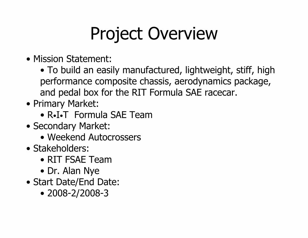
Project Overview
• Mission Statement:• To build an easily manufactured, lightweight, stiff, high performance composite chassis, aerodynamics package, and pedal box for the RIT Formula SAE racecar.
• Primary Market:• R•I•T Formula SAE Team
• Secondary Market:• Weekend Autocrossers
• Stakeholders:• RIT FSAE Team• Dr. Alan Nye
• Start Date/End Date:• 2008-2/2008-3

Components for RedesignCustomers Interviewed:• Formula SAE Driver, Project Manager, Chassis Designer, & Chief Engineer• SCCA Autocrosser
Customer Needs (Pedal Box):• Stiff• Lightweight• Adjustable• Easily Manufactured
Customer Needs (Undertray):• Center of pressure near CG of car• Lightweight• Easily manufactured• Makes Downforce• Does not interfere with car operation
Customer Needs (Chassis):• Torsionally Stiff• Lightweight• Ergonomic• Test Procedure for Correlation• Works with F16’s other parts
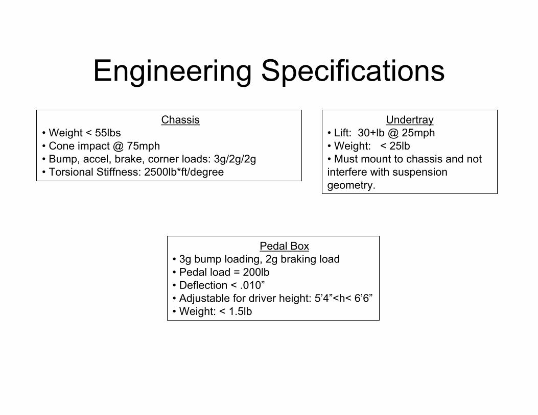
Engineering Specifications
Pedal Box• 3g bump loading, 2g braking load• Pedal load = 200lb• Deflection < .010”• Adjustable for driver height: 5’4”<h< 6’6”• Weight: < 1.5lb
Undertray• Lift: 30+lb @ 25mph• Weight: < 25lb• Must mount to chassis and not interfere with suspension geometry.
Chassis• Weight < 55lbs• Cone impact @ 75mph• Bump, accel, brake, corner loads: 3g/2g/2g• Torsional Stiffness: 2500lb*ft/degree

Resin Selection
Polyester:Pros:• Cheap• Low viscosity• Properties can be tailored
Cons:• Poor adhesive characteristics• Relatively brittle and weak• Large number of ester groups means water has significant effect on properties due to hydrolysis• High degree of shrinkage
VinylesterPros:• Relatively cheap• Low viscosity• Good mechanical properties• Fewer ester groups than polyester, more resistant to ingress of water• High toughness because active sites are at ends of molecular chains
Cons:• High degree of shrinkage• Relatively poor adhesive qualities
EpoxyPros:• Excellent thermal and mechanical properties due to cyclic groups (instead of linear chains)• Ethylene Oxide groups instead of ester groups – high resistance to water• Reaction sites are at ends of molecular chains – high toughness• Excellent adhesive properties
Cons:• High viscosity• Cost
Idealized Polyester Molecule(Isophthalic)
Idealized Epoxy Molecule(Bisphenol A)
Idealized Vinylester Molecule
Idealized Ethylene Oxide Group (Epoxy)

Resin Selection

Resin Selection
Selection Criteria:
• Elasticity/Toughness• Adhesion Properties• Strength• Water Degradation• Resistance to Corrosives• Viscosity• Cost
Selected Matrix: Epoxy
• Highest Fatigue/Creep Resistance• Highest Resistance to Water & Corrosives

Fiber Selection
Selected Fiber: Carbon Fiber
• Highest specific stiffness• Very little sacrifice in strength• More experience with CF

Composite MonocoqueMonocoque Style
Above: Full Monocoque(RMIT)
Above: Partial Monocoque(TU Graz)
Above: Partial Monocoque Roll Hoop Mounting(ETS)

Composite MonocoqueMonocoque Style
Partial Monocoque:
Pros:• Less carbon = cheaper• Ease of manufacturing
• Smaller monocoque footprint means easier time finding oven/autoclave• Fewer molds and less lay-up time
• Easy engine mounting scheme
Cons:• Different suspension mounting scheme front and rear• Extensive welding required
Full Monocoque:
Pros:• Solutions for suspension mounting can be applied to both front and rear• Continuous fabric rear box is likely stiffer and stronger than steel rear• Less time, if any, spent welding
Cons:• More expensive• Difficult to transition to steel roll hoop, then back to carbon• Difficulty in engine mounting• Larger footprint restricts oven choices
Concept Selected: Partial Monocoque
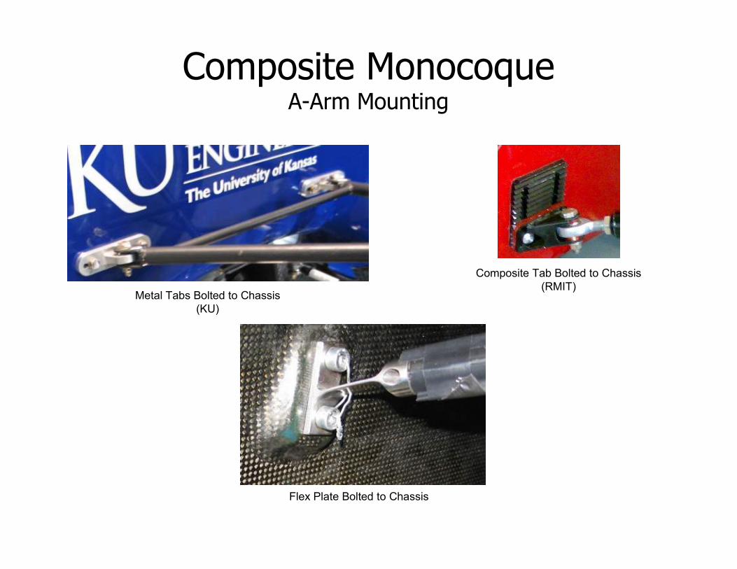
Composite MonocoqueA-Arm Mounting
Metal Tabs Bolted to Chassis(KU)
Composite Tab Bolted to Chassis(RMIT)
Flex Plate Bolted to Chassis

Composite MonocoqueA-Arm Mounting
Tabs (carbon or metal):
Pros:• Minimal alteration of vehicle’s kinematics• Longer lifetime (no reversing flexural loads)
Cons:• Heavy• Expensive bearings• Subject to bearing supplier’s lead times
Flex Plates:
Pros:• Lightweight• Simple design with very few parts
Cons:• Changes spring rate of vehicle• Reversing flexural loads decrease fatigue life
Concept Selected: Tabs Bolted to Chassis
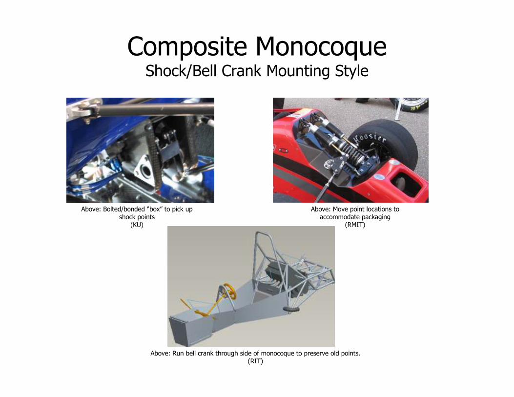
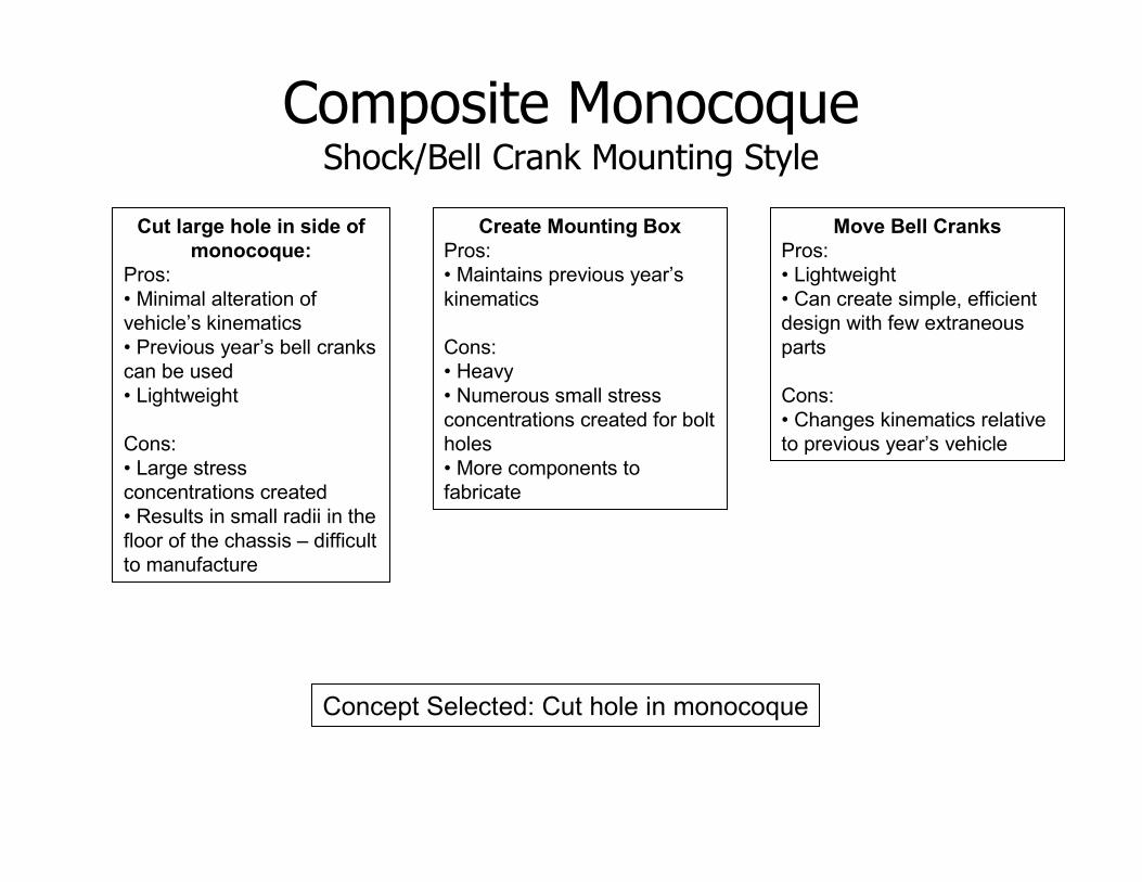
Composite MonocoqueShock/Bell Crank Mounting Style
Above: Run bell crank through side of monocoque to preserve old points.(RIT)
Above: Bolted/bonded “box” to pick up shock points
(KU)
Above: Move point locations to accommodate packaging
(RMIT)
Composite MonocoqueShock/Bell Crank Mounting Style
Cut large hole in side of
monocoque:
Pros:• Minimal alteration of vehicle’s kinematics• Previous year’s bell cranks can be used• Lightweight
Cons:• Large stress concentrations created• Results in small radii in the floor of the chassis – difficult to manufacture
Move Bell Cranks
Pros:• Lightweight• Can create simple, efficient design with few extraneous parts
Cons:• Changes kinematics relative to previous year’s vehicle
Concept Selected: Cut hole in monocoque
Create Mounting Box
Pros:• Maintains previous year’s kinematics
Cons:• Heavy• Numerous small stress concentrations created for bolt holes• More components to fabricate

Composite MonocoqueChassis Analysis
Governing Equation of Finite Element Analysis:
• Garbage In = Garbage Out
FEM must:• Have quickly traced and resolved errors• Run “quickly” on school computers• Be robust enough to easily run multiple load cases• Comprehend composite-to-steel interface at roll hoop mounts• Be easily modified• Be accurate
FEA Package Chosen: ANSYS

Composite MonocoqueChassis Analysis
Steps for Building Model(Note: All steps will be completed first by modeling composite components with equivalent isotropic properties.
After successful runs, full laminate will be modeled)
• Model a channel with min & max chassis radii.
• Model front half of chassis, apply arbitrary loads and constraints.
• “Bond” both steel roll hoops (beam elements) to monocoque (shell elements). Apply arbitrary loads and constraints
• Increase roll hoop element count, connect nodes from roll hoop elements to shell elements. Use beam elements with fastener material & geometric properties.
• Add rear of chassis as beam elements. Run model with realisticloads/constraints (coarse mesh)
• Model small chassis segments w/ very fine mesh. Apply displacements (taken from global coarse grid model) at boundaries. Check for strain, stress, buckling, etc..

• Chassis plug used as accurate base for chassis manufacture
• 2 plugs will be made, one representing top half geometry, one representing bottom half geometry
• Plugs will be CNC manufactured out of MDF primarily for accuracy, but also to minimize manufacturing time
• MDF cost (~$400) is a major concern
• Surface will be finished with sanded/polished paint and coated with mold release
Top and Bottom Plugs (CSU Northridge)
Initial Bottom Plug Design
Composite MonocoqueChassis Plug
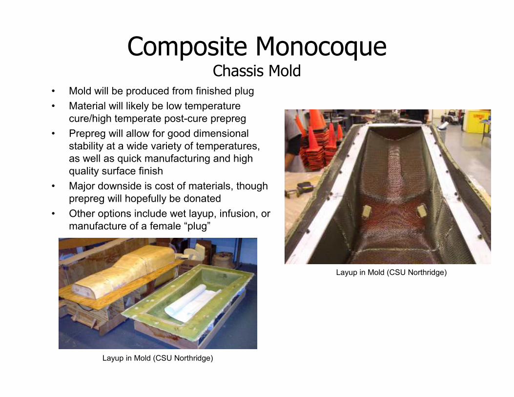
• Mold will be produced from finished plug
• Material will likely be low temperature cure/high temperate post-cure prepreg
• Prepreg will allow for good dimensional stability at a wide variety of temperatures, as well as quick manufacturing and high quality surface finish
• Major downside is cost of materials, though prepreg will hopefully be donated
• Other options include wet layup, infusion, or manufacture of a female “plug”
Layup in Mold (CSU Northridge)
Layup in Mold (CSU Northridge)
Composite MonocoqueChassis Mold

• Aerospace prepreg will be cured in an autoclave at high temperature and pressure
• Process assures very high quality, consistent part and allows use of high performance resins
• Cost of materials is very high, but they will hopefully be donated
Lower Chassis Half (CSU Northridge)
Autoclave Cure of Components (CSU Northridge)
Lower Chassis Model
Composite MonocoqueFinal Part

Composite MonocoqueOverall Cost

Left: Concept pedal box assembly including:- Pedals
- Bias block- Footrest
Right: Load cases to be considered:- Driver input reactions
- Bump loading
Composite Pedal BoxConcept Development

Composite Pedal BoxStiffening Concepts
Above: Design combing flat plate and rib-style concepts(in progress)Upper-left: Flat plate concept
Left: Rib-style concept

Composite Pedal BoxAnalysis & Testing
Test Plan:
• Destructive testing to verify:• Fabric/matrix properties • Pin pull-out• Bias-block tabs
• Determine required material thicknesses
Analysis Plan:
• ANSYS Workbench• “Iso” properties• Estimate deflection• Estimate thickness
• ANSYS Classic• Refine thickness & ply orientation• Ply stress analysis
• ANSYS Workbench• Bond-line analysis• Determine suitable structural adhesive

Composite Pedal BoxManufacturing
Mold Concept:
• Two piece compression-molding:• Tray• Bias block tabs• Stiffening plates
• Possible materials include:• MDF• Plastic• Aluminum
Above: Lower mold concept

Composite Pedal BoxOverall Cost

Composite UndertrayUndertray Images
Rear Tunnels of TU Graz’s Undertray Side view of TU Graz’s Undertray
Underside of TU Graz’s Undertray
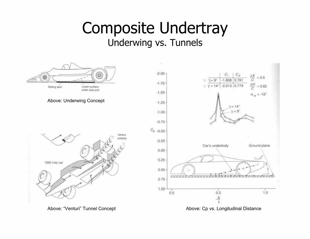
Composite UndertrayUnderwing vs. Tunnels
Above: Underwing Concept
Above: “Venturi” Tunnel Concept Above: Cp vs. Longitudinal Distance
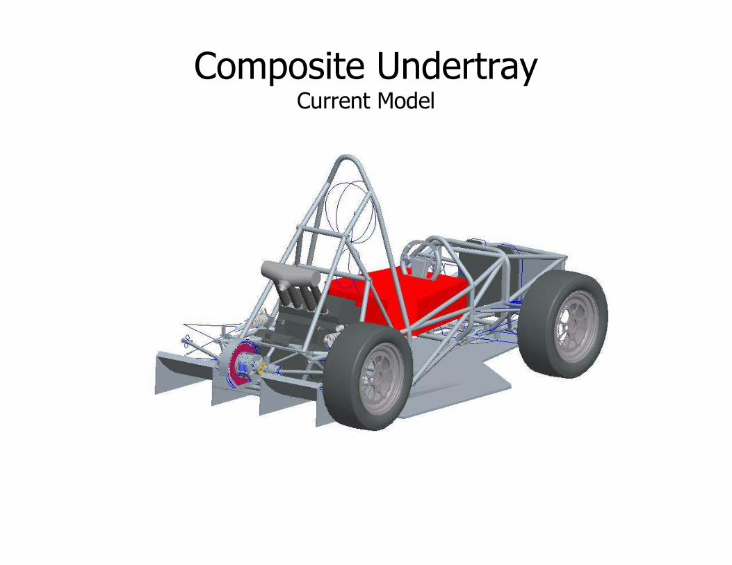
Composite UndertrayCurrent Model
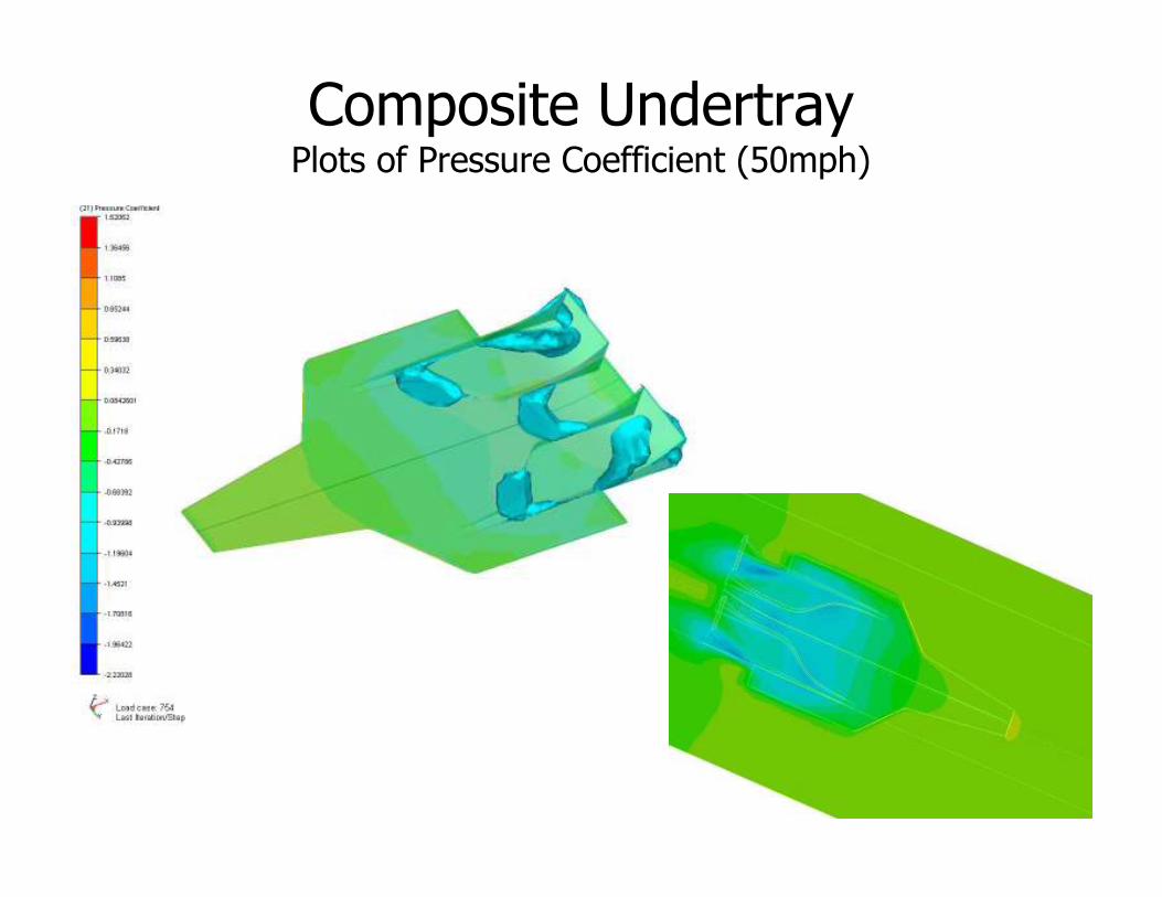
Composite UndertrayPlots of Pressure Coefficient (50mph)
Salvo, please insert Cp results plot

Composite UndertrayPlot of Velocity Gradient (25mph)
Salvo, please insert velocity results plots

Composite Undertray
Salvo, please insert downforce vs. speed results plots
Forces vs Vehicle Speed
27.6
56.5
249.8
3.1 6.213.54
29
122.25
0
50
100
150
200
250
300
0 10 20 30 40 50 60 70 80
Vehicle Speed (mph)
Force (lbs)
Li ft (-Z)
Drag (-X)
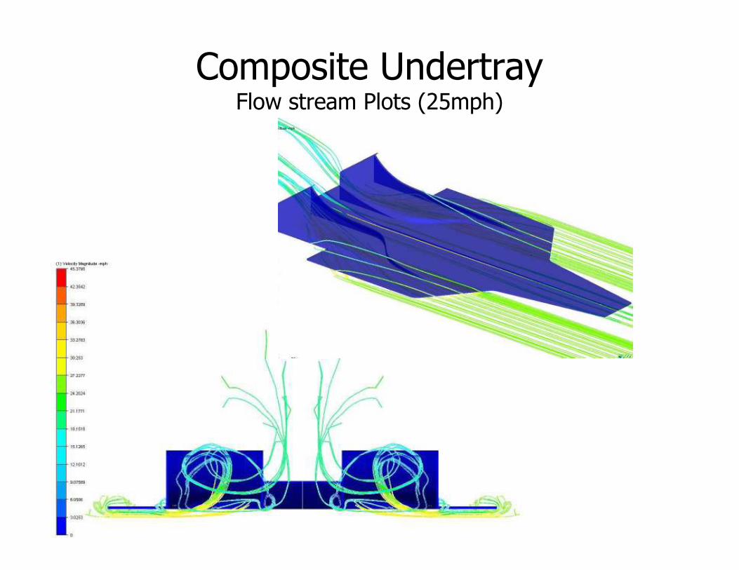
Composite UndertrayFlow stream Plots (25mph)

Composite UndertrayManufacturing
Undertray Manufacturing Process:
• Mold “roughed out” with a hot wire and foam block
• “Rough” mold bonded to wooden base
• Fiberglass overlaid onto foam
• Bond-o applied over fiberglass
• Final prep for mold (painting, wet sanding, fine bond-o work, etc…)
• Wet lay-up performed
• Vacuum bag applied.
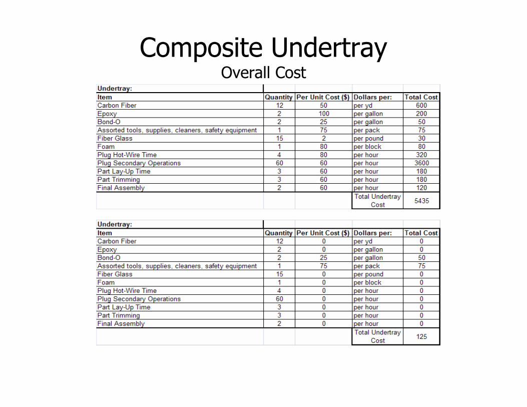
Composite UndertrayOverall Cost

Verification of Components
• Had meeting with PCB Piezotronics
– January 9th, 2009
• Looking for sensors to validate designs
– Decided upon strain gages and load cells
• Sent in “wish list” for desired sensors
– Waiting on pricing quote

Verification of Components
• Strain gage– Model 740B02 – Dynamic ICP
Strain Sensor• 50 mV/µε sensitivity
• 0.5Hz to 100kHz frequency range
• 0.02 oz in weight
• 0.6 nε resolution
• Integral 10ft cable with 10-32 coaxial plug
• Reusable
• Used for strain measurement at various locations on the chassis
• Four units requested

Verification of Components
• Load Cells– Model 222B
• Used for pullrod force measurement• 2500 lb tension range• 2.00 oz in weight• 0.9 mV/lb• Two units requested
– Model 221B05• Used for pushrod force measurement• 5000lb compression range• 1.1 oz in weight• 1 mV/lb• Two units requested

Verification of Components
• Undertray verification uses load cells– A load cell in each pushrod and pullrod will allow for
direct measurements of downforce and pressure center.
• Chassis verification uses strain gages– Strain gages distributed about the chassis will allow
for FEA Model verification
– Coupling with loads gathered with load cells and accelerometers will allow for FEA analysis using empirically measured loads and compare measured strain to theoretical strain.

• Gurit's Guide to Composites: www.gurit.com• Introduction to Composite Materials Design by Ever J. Barbero• Race Car Aerodynamics by Joseph Katz
Sources