system-level hazard analysis using the sequence-tree … hazard... · system-level hazard analysis...
TRANSCRIPT
Available online at www.sciencedirect.com
www.elsevier.com/locate/anucene
Annals of Nuclear Energy 35 (2008) 353–362
annals of
NUCLEAR ENERGY
System-level hazard analysis using the sequence-tree method
Hui-Wen Huang a,b,*, Chunkuan Shih a, Swu Yih c, Ming-Huei Chen b
a Department of Engineering and System Science, National Tsing-Hua University, 101, Section 2 Kuang Fu Road, Hsinchu, Taiwanb Institute of Nuclear Energy Research, No. 1000, Wenhua Road, Chiaan Village, Longtan Township, Taoyuan County 32546, Taiwanc Department of Computer Science and Information Engineering, Ching Yun University, 229, Chien-Hsin Road, Jung-Li City, Taiwan
Received 20 February 2007; received in revised form 18 July 2007; accepted 22 July 2007Available online 4 September 2007
Abstract
A system-level PHA using the sequence-tree method is presented to perform safety-related digital I&C system SSA. The conventionalPHA involves brainstorming among experts on various portions of the system to identify hazards through discussions. However, sincethe conventional PHA is not a systematic technique, the analysis results depend strongly on the experts’ subjective opinions. The qualityof analysis cannot be appropriately controlled. Therefore, this study presents a system-level sequence tree based PHA, which can clarifythe relationship among the major digital I&C systems. This sequence-tree-based technique has two major phases. The first phase adopts atable to analyze each event in SAR Chapter 15 for a specific safety-related I&C system, such as RPS. The second phase adopts a sequencetree to recognize the I&C systems involved in the event, the working of the safety-related systems and how the backup systems can beactivated to mitigate the consequence if the primary safety systems fail. The defense-in-depth echelons, namely the Control echelon,Reactor trip echelon, ESFAS echelon and Monitoring and indicator echelon, are arranged to build the sequence-tree structure. Allthe related I&C systems, including the digital systems and the analog back-up systems, are allocated in their specific echelons. This sys-tem-centric sequence-tree analysis not only systematically identifies preliminary hazards, but also vulnerabilities in a nuclear power plant.Hence, an effective simplified D3 evaluation can also be conducted.� 2007 Elsevier Ltd. All rights reserved.
0306-4549/$ - see front matter � 2007 Elsevier Ltd. All rights reserved.
doi:10.1016/j.anucene.2007.07.010
Abbreviations: ABWR, advanced boiling water reactor; ADS, auto-matic depressurization system; ARI, alternate rod insertion; ATM, analogtrip module; ATWS, anticipated transient without scram; BTP, branchtechnical position; CMF, common mode failure; CPU, central processingunit; D3, diversity and defense-in-depth; ECCS, emergency core coolingsystem; ESFAS, engineered safety features actuation system; FMCRD,fine motion control rod drive; FMEA, failure modes and effects analysis;FWP, feedwater pump; FTA, fault tree analysis; HPCF, high pressurecore flooder; I&C, instrumentation and control; INER, Institute of Nu-clear Energy Research; LOCA, loss of coolant accident; LPFL, low pre-ssure core flooder; NPP, Nuclear Power Plant; NRC, Nuclear RegulatoryCommission; NTHU, National Tsing Hua University; PCTran, personalcomputer transient analyzer; PHA, preliminary hazard analysis; RCIC,reactor core isolation cooling; RFC, recirculation flow control system;RHR, residual heat removal system; RIP, reactor internal pump; RPS,reactor protection system; Rx, reactor; SAR, safety analysis report; SBPC,steam bypass and pressure control system; SCM, software configurationmanagement; SLCS, standby liquid control system; SSA, software safetyanalysis; SV&V, software verification and validation.
* Corresponding author. Address: Department of Engineering andSystem Science, National Tsing-Hua University, 101, Section 2 KuangFu Road, Hsinchu, Taiwan. Tel.: +886 (3) 4711400x6352; fax: +886 (3)4711415.
E-mail address: [email protected] (H.-W. Huang).
1. Introduction
Many recent NPP designs utilize digital control sys-tems. Digital control systems have the following advanta-ges: (1) no setpoint drifting; (2) automatic calibration; (3)various improvement capabilities, such as fault tolerance,self-testing, signal validation and process system diagnos-tics, and (4) much detailed information helping operatorsto discover the plant status. However, digital control sys-tems induce new failure modes that differ from those ofanalog control systems. Analog systems comprise logiccircuits, each of which can obtain its own logical resultindependently. In contrast, a digital system is run on acomputer. All the logic circuits are transferred to soft-ware, and all the logical computations should be per-formed by the CPU. Thus, all the software should berun by the CPU. The software should be allocated inmemory, possibly producing problems of address conflictand memory overflow. The transfer digital data also raisesissues of communication through the network. Redundant

354 H.-W. Huang et al. / Annals of Nuclear Energy 35 (2008) 353–362
system design can help resist against single failure. How-ever, the redundant system typically implements the samesoftware module as the original system. This indicatesthat software CMF can defeat the redundant system.Therefore, digital I&C systems must address issue of soft-ware failure. Branch Technical Position HICB-14 (BTP-14), ‘‘Guidance on Software Reviews for Digital Com-puter-Based I&C Systems (1997)’’, requests SV&V andSCM to reduce the number of software errors, and thusenhance software reliability. However, error-free softwareis impossible to achieve in a complicated digital system. Inparticular, some software faults are not detectable,because they take effect only in particular contexts. There-fore, SSA and D3 can improve the system safety whereverthe software fault takes effect on the NPP. SSA identifiesthe system hazards introduced by software failure. D3focuses on plant level defense against safety-related digitalI&C system failure. Fault-tolerance techniques can suc-cessfully resolve software or hardware single failure. Leeet al. (2001) presented a best-estimate analysis methodol-ogy to perform defense-in-depth and diversity evaluationfor the Korean Next Generation Reactor. Lee et al.(2006) also proposed an evaluation method of error detec-tion coverage and fault tolerance to perform safety assess-ment of the digitalized system. Liu et al. (2007) employedstate-based modeling to perform safety analysis of soft-ware product lines. However, software common modefailure can defeat the fault-tolerance architecture. D3evaluation should be performed to cope with the softwareCMF issue. The US NRC states the requirement for D3in Branch Technical Position HICB-19 (BTP-19), ‘‘Guid-ance for Evaluation of Defense-in-Depth and Diversity inDigital Computer-Based Instrumentation and ControlSystems (1997)’’ and SECY 93-087, ‘‘Defense againstCommon-Mode Failures in Digital Instrumentation andControl System, Staff Requirement Memorandum(1993).’’ Software CMF is the major concern. The diversebackup system is an acceptable consideration, and can bean automatic analog system with the same function ormanual system-level actuation function. BTP-19 (1997)also endorsed NUREG/CR-6303, ‘‘Method for Perform-ing Diversity and Defense-in-depth Analyses of ReactorProtection Systems (1994)’’ as an acceptable D3 analysismethod. Although replacing the obsolete analog systemis one of the objectives of I&C system digital upgrade,the digitalized NPP currently still need the analog systemas a backup.
Several SSA techniques, including preliminary hazardanalysis, failure modes and effects analysis, fault treeanalysis, system modeling, software requirements hazardanalysis, walkthroughs and simulator/plant model testing,are described in Annex D of IEEE 7.4.3.2-2003, ‘‘Identi-fication and resolution of hazards (2003)’’. Markov chainmodeling and dynamic flowgraph methodology can alsobe adopted in SSA. NUREG/CR-6430, ‘‘Software SafetyHazard Analysis (1995)’’ and IEEE Std. 1228-1994,‘‘IEEE Standard for Software Safety Plans (1994)’’
described in detail the procedure for performing SSA.IEEE Std. 1044-1993, ‘‘IEEE Standard Classificationfor Software Anomalies (1993)’’ describes a uniformapproach to classification of anomalies found in softwareand its documentation. Some SSA techniques adoptquantitative parameter, such as failure rate or transitionprobability, for PRA and risk-informed decision making.However, software faults are caused by design error. Themechanism of software failure is different from the agingprocess of hardware failure. It means the software failurerate is very hard to measure. Hence, qualitative tech-niques, such as PHA, FMEA, and FTA (without soft-ware failure rate), are the major SSAs adopted atINER, Taiwan (see Fig. 1). If the hazard cannot be suc-cessfully identified for some specific complex cases, simu-lator-based analysis will be used to analyze the dynamicrelationships among I&C systems. If thermal hydraulicsafety analysis is still required, then RETRAN (2007a,2007b) or RELAP (2007) are applied to confirm thedetails (such as pressure boundary or fuel integrity) accu-rately. At INER, Swu et al. (2004) and Huang et al.(2005, 2006a,b, 2007a,b) have utilized the Simulator-based model technique by PCTran-ABWR (1981) foryears. Micro-Simulation Technology (2007) producedPCTran-ABWR, a faster-than-real-time plant simulationcomputer code. This code was developed to evaluatethe transients and accidents of ABWR. INER andNTHU (Taiwan) are involved in a long-term collabora-tion project to extend and improve this code. To clarifythe properties of SSA techniques, Huang et al.(2006c,d) presented developed an evaluation method forsoftware hazard identification techniques. The SSA teamof INER adopted this evaluation method to obtain astrategy to adopt SSA techniques combination includingPHA, FMEA, FTA (without failure rate), and a simula-tor-based model technique.
Conventional PHA adopts a critical function list and achecklist to guide and focus discussions. The role of theanalyzed safety-related system, such as RPS or ECCS,in a postulated event or accident cannot be obviouslyclarified. Moreover, the relationship among the involvedI&C systems still cannot be clearly described. Further-more, since this conventional PHA is not a systematictechnique, the analysis result depends strongly on theexperts’ subjective opinions. The analysis quality cannotbe suitably managed. Therefore, this study presents a sys-tem-level sequence-tree-based PHA, which can systemati-cally clarify the relationship among the major digitalI&C systems.
The proposed sequence-tree-based technique has twomajor phases. The first phase applies a table to analyzeeach event in SAR Chapter 15, ‘‘Accident Analysis’’, fora specific system. The second phase adopts a sequence treeto identify the I&C systems that are involved in the event,how the safety-related systems work, and how the backupsystems can be activated to mitigate the consequences offailure of the primary safety systems.

Fig. 1. Current hazard identification application status at INER.
Table 1Generic SAR event analysis table
Analyzed system Section Title Event description The role of analyzedsafety-related I&C system
Mitigation means
The name ofanalyzedsafety-relatedI&C system
SARsectionnumber
SAReventtitle
The block describes theevent sequence and theI&C system involved in theevent
The block describes therole of analyzed safety-related I&C system in theevent
How the diverse backup systems mitigate theconsequence of event what if the analyzed safety-related I&C system fails to perform itsdesignated function
1 ESFAS is not for backing up the reactor trip system in case of failure.It is utilized to compensate for coolant loss exceeding the normal feedcapacity. It is activated even if the reactor trip succeeds.
H.-W. Huang et al. / Annals of Nuclear Energy 35 (2008) 353–362 355
2. SAR event analysis table
The SAR event analysis table can determine how a pri-mary safety-related digital I&C system performs its func-tion in an event, and how the mitigation methodperforms the backup function if the primary digital I&Cfails. Table 1 presents a generic SAR event analysis table.The columns of an SAR event analysis table are ‘‘analyzedsystem’’, ‘‘section’’, ‘‘title’’, ‘‘event description’’, ‘‘the roleof analyzed safety-related I&C system’’ and ‘‘mitigationmethod’’.
‘‘Section’’ and ‘‘title’’ indicate the analyzed event, forexample, ‘‘15.1.1 Loss of Feedwater Heating’’ or ‘‘15.2.1Pressure Regulator Failure – closed’’. The ‘‘Event descrip-tion’’ column describes the event sequence and I&Csystem involved in the event. ‘‘The role of analyzedsafety-related I&C system’’ describes the role of the ana-lyzed safety-related I&C system in the event. ‘‘Mitigationmethod’’ describes how the diverse backup systems miti-gate the consequence of events if the analyzed safety-related digital I&C system fails to perform its designatedfunction.
3. Sequence-tree method
NUREG/CR-6303 (1994) defines Echelons of defense as‘‘specific applications of the principle of defense-in-depthto the arrangement of instrumentation and control systemsattached to a nuclear reactor for the purpose of operatingthe reactor or shutting it down and cooling it.’’ For anuclear power plant, ‘‘the echelons are the control system,the reactor trip or scram system, the Engineered SafetyFeatures actuation system (ESFAS), and the monitoringand indicator system. The echelons may be considered tobe concentrically arranged in that when the control systemfails, the reactor trip system shuts down reactivity; whenboth the control system and the reactor trip system fail,1
the ESFAS continues to support the physical barriers toradiological release by cooling the fuel, thus allowing timefor other measures to be taken by reactor operators toreduce reactivity. All four echelons depend upon sensorsto determine when to perform their functions, and a serious
356 H.-W. Huang et al. / Annals of Nuclear Energy 35 (2008) 353–362
safety concern is to ensure that no more than one echelon isdisabled by a common sensor failure or its directconsequences.’’
The sequence-tree method can identify what I&C sys-tems are involved in the event, how the safety-related sys-tems work, and how the backup systems can be activatedto mitigate the consequences of failure of the primarysafety systems. The defense-in-depth echelons, namely theControl echelon, RPS echelon, ESFAS echelon, and Mon-itoring and indicator echelon, are arranged in the sequencetree to build the structure. All the related I&C systems, i.e.the digital systems and the analog back-up systems, areallocated in their specific echelons.
Fig. 2 illustrates a generic sequence tree. A sequencetree denotes a specific SAR event. Each SAR event is ini-tiated by a transient initiation system. The transient initi-ation system can be a control system, an ESFAS systemor a mechanical system. Abnormal behavior in a tran-sient initiation system could induce a plant-level tran-sient. For instance, in the ‘‘Loss of Feedwater Heating’’event, closure of the steam extraction line to the heatercan cause the loss of a feedwater heater. In ‘‘FeedwaterController Failure-Maximum Demand’’ event, the rootcause is postulated as a single failure of a control device.The former is a mechanical failure, while the latter is acontrol system failure. The transient initiation systemcan induce some plant parameter changes, such as adecrease in vessel water level or an increase in vesselpressure.
The control echelon contains non-safety equipment thatroutinely prevents reactor excursions toward unsafe opera-tion regimes, and is adopted for normal operation of thereactor. A small transient can be eliminated by the controlechelon and the reactor physical response itself. Forinstance, the feedwater control system can eliminate a smallfeedwater flow perturbation, so that the plant reaches thebalanced state. However, if the transient is sufficiently vio-lent, then the reactor might scram due to the low waterlevel in the reactor vessel. The control echelon can also per-form mitigation. For instance, runback or trip of reactorinternal pumps by some pre-set condition can reduce thereactor core flow, and consequently reduce the reactorpower.
The reactor trip echelon consists of safety equipmentthat is designed to reduce reactivity rapidly in responseto an uncontrolled excursion. If the digital RPS doesnot perform the normal reactor scram, then thebackup/alternative automatically initiates the reactorshutdown function to mitigate the consequences of thisfailure. For instance, ATM and FMCRD run-in arethe backup/alternative reactor shutdown functions ofRPS in ABWR. ATM, which receives hard-wired waterlevel signal, can transmit a reactor trip signal to initiateFMCRD run-in at the setpoint below that of RPS.FMCRD run-in is a motor driven control rod insertionprocedure, which is different from the hydraulic rodinsertion mechanism of RPS. Manual scram by the oper-
ator through hard-wiring is the last defense line of thereactor trip echelon. However, the operator should relyon the monitoring and indication echelon to recognizethe abnormal situation.
The ESFAS echelon consists of safety equipment thatremoves heat or otherwise assists in maintaining the integ-rity of the three physical barriers to radioactive release(cladding, vessel and containment). The major system setof ESFAS for an ABWR is ECCS, which comprises digi-tized RCIC, HPCF and LPFL. Each of these systems caninject water by its specific low water level setpoint or highdrywell pressure setpoint. Diverse means are designedbehind the digital ESFAS systems to mitigate the softwarecommon mode failure of the digital system. The systemscan be automatic analog systems or manual push-buttonsystems.
The monitoring and indication echelon is a set of sen-sors and safety parameter displays. This echelon includesthe primary digital monitoring and indication systems,and the diverse backup devices. The operator can identifythe plant status while a transient is progressing from thestatus of this echelon. If RPS or ESFAS cannot performtheir function properly, then the operator can take manualaction with the monitoring and indication echelon to pre-vent further plant deterioration. Additionally, the analogmonitoring and indication system is designed to back upthe digital system in the event of software common modefailure.
The time-axis of the sequence-tree method can onlyroughly describe the sequence of activities in the event.The method cannot describe precisely the dynamic changeof each parameter. A nuclear power plant simulation com-puter code should be adopted in this situation if furthertime-dependent details need to be recognized. Fig. 3 illus-trates an example of trend plot analyzed using PCTran-ABWR. However, the trend plot cannot directly describethe relationships among the systems. Hence, a combinationanalysis is required to observe all the views of systeminteractions.
4. Case study
Two safety-related I&C system cases, each involving aspecific SAR event, were analyzed. Conventional eventanalysis assumes that all the safety-related I&C systemfunctioned properly. However, the case studies in thisstudy assumed that one or more safety-related I&C systemsfailed. Moreover, the system-level interactions were ana-lyzed, and the D3 means were also evaluated.
4.1. Reactor protection system
The RPS case study in this study analyzed the ‘‘feed-water controller failure-maximum demand’’ event by theABWR SAR event analysis table and sequence-treemethod. All the RPS-involved events in SAR should beselected and analyzed for a complete RPS analysis.

Fig. 2. Generic sequence tree.
H.-W. Huang et al. / Annals of Nuclear Energy 35 (2008) 353–362 357
Table 2 presents an analysis of the RPS case study event.The ‘‘feedwater controller failure-maximum demand’’event is presented in SAR Section 15.1.2. This eventassumes feedwater controller failure at maximum demand.In this case, the feedwater flow rises due to the abnormallyhigh speed of two turbine-driven feedwater pumps. The
water level rises to the high-level set point (Level 8), induc-ing main turbine trip and feedwater pump trip. Conse-quently, the water level falls to the low-level set point(Level 3), which induces reactor scram. The analyzedsafety-related I&C system, namely digitalized RPS, triggersa scram signal due to a low reactor-vessel water level (Level

Fig. 3. Example of trend plot analyzed by PCTran-ABWR.
Table 2Analysis table case study on RPS failure event
Section Title Event description The role of analyzed safety-related I&C system
Mitigation means
SAR Section15.1.2
Feedwater controller failure –maximum demand
� Feedwater controller failureleading to maximumdemand� Feedwater flow rises� Water level rises to high
level induces turbine tripand feedwater pump trip� Water level falls to low level
induces reactor scram
RPS triggers scram signal dueto low reactor vessel water level(Level 3)
If RPS fails to scram when thelevel falls to Level 3, then thefollowing diversified mitigationmeans are initiated
(1) When water level isbelow Level 2, the analogtrip module (ATM) will ini-tiate alternate rod insertion(ARI), fine motion controlrod drive (FMCRD) run-into shut down the reactor.Boron Injection is initiatedat 3 min after water levelreaches Level 2(2) The hard-wired levelindication and low-levelalarm notify the operatorto manually scram thereactor
358 H.-W. Huang et al. / Annals of Nuclear Energy 35 (2008) 353–362
3). If the digitalized RPS fails to scram when the level fallsto Level 3, then the following diverse mitigation means areinitiated. (1) The analog trip module (ATM) initiates thealternate rod insertion (ARI) and fine motion control roddrive (FMCRD) run-in to shutdown the reactor when thewater level falls below Level 2. (2) Boron Injection is initi-ated at 3 min after the water level reaches Level 2. (3) Thehard-wired level indication and low-level alarm notifies theoperator to scram the reactor manually.
Fig. 4 displays the RPS sequence-tree case study. In the‘‘feedwater controller failure-maximum demand’’ event,the feedwater control system is the transient initiator, caus-ing the water level to rise to Level 8. In the control echelon,the high reactor water level signal triggers the feedwaterpump trip and the main turbine trip to prevent water fromflowing into the main steam lines. The 10 turbine bypassvalves rapidly open to release the steam to avoid high reac-tor pressure. Since the reactor power is still at a high level,and no feedwater enters the reactor vessel, the water level
falls to low (Level 3). Four RIPs are tripped due to thelow water level.
In the reactor trip echelon, Level 3 is the reactor scramsetpoint. If the reactor is normally scrammed, then thewater level change rate falls significantly. This case studyassumed that the digitalized RPS fails to trip the reactor(i.e. ATWS) due to software CMF. The hazards of RPSfailure can be identified as (1) the water level continuouslyfalls rapidly, and (2) the core uncovery potential risessimultaneously. Some diverse backup means were designedto mitigate the hazard. ARI and FMCRD run-in are initi-ated if the water level subsequently drops to Level 2. Toavoid using the common signal type software CMF, theanalog water level instrument is diverse from the primarydigital water level signal. The ATM transmits the reactorshutdown signals ARI, FMCRD run-in and SLCS whenthe water level is below Level 2. The ARI can open thealternate valves to release a hydraulic driving force, so thatcontrol rods can be inserted. This alternate driving force is

Fig. 4. RPS sequence tree case study.
H.-W. Huang et al. / Annals of Nuclear Energy 35 (2008) 353–362 359
360 H.-W. Huang et al. / Annals of Nuclear Energy 35 (2008) 353–362
not as strong as that of the primary reactor scram. TheFMCRD run-in adopts a motor to insert the control rods,and takes even longer to perform reactor shutdown. TheSLCS injects boron to the reactor 3 min after the waterlevel reaches Level 2 if the control rod still fails to insert.Hard-wired manual scram is the last defense line of reactorshutdown performed by the operator.
In the ESFAS echelon, RCIC is initiated if the waterlevel reaches Level 2. If the reactor is successfullyscrammed, then RCIC begins to inject water into the reac-tor vessel to avoid core uncovery. However, the high reac-tor power consumes water quite rapidly in the ATWS case.Consequently, the water level might reach Level 1.5 andinitiate HPCF. Manual HPCF hard-wired initiation is analternate means to ensure that the reactor core can be cov-ered under water.
In the monitoring and indication echelon, the digital-ized monitoring and indication system continuously pro-vides information about the water level and pressure ofthe reactor vessel. Additionally, the diverse reactor waterlevel sensor and instrument, the diverse reactor waterlevel display and the diverse reactor water level lowalarm can provide alternate information to help the oper-ator determine whether to take manual action to shut thereactor down or inject water into the reactor. This anal-ysis result of the case study reveals that the diverse mit-igation means design is sufficient to protect the fuel andthe NPP in the ‘‘feedwater controller failure-maximumdemand’’ event.
4.2. Emergency core cooling system
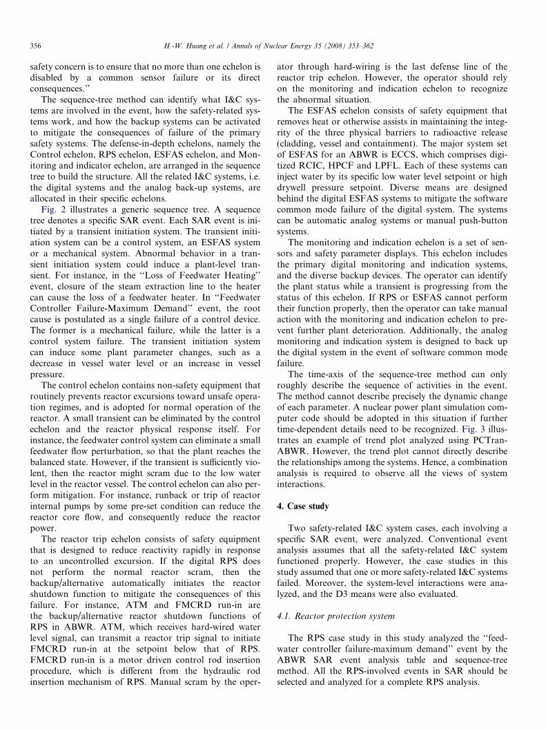
The ECCS case study analyzed the ‘‘LOCA-HPCF linebreak’’ event in the ABWR SAR event analysis table andsequence-tree method. ECCS is designed to mitigate theconsequence of LOCA. All the ECCS-involved events inSAR should be selected and analyzed for a complete ECCSanalysis. A significant improvement in ABWR is the rede-sign of the recirculation pumps with an outer loop recircu-
Table 3Analysis table case study on HPCF failure event
Section Title Event description
SAR Section 6.3 LOCA-HPCF line break � Assume HPCF line break� Rx scram due to water le
falling to Level 3� RCIC initiated due to wa
level falling to Level 2� HPCF line is broken, the
fore no HPCF injectiowhen water level falls to Le1.5� MSIV closed due to wa
level falling to Level 1.5� ADS opened and LPFL in
ated due to water level fallto Level 1
lation line to reactor internal pumps. Hence, the majorLOCA considerations are the main steam line break, thefeedwater line break and the HPCF line break, which aremuch less severe than the recirculation line break.
Table 3 shows the event analysis of the ECCS casestudy. The ‘‘LOCA-HPCF line break’’ event is describedin SAR Section 6.3. The event initiator is the HPCF linebreak. The water level starts to fall due to LOCA. Thereactor scrams when the water level falls to Level 3.RCIC is initiated when the water level falls to Level2. This event assumes one HPCF line break, meaningthat another HPCF cannot start due to diesel generatorfailure. No HPCF water is injected when the water levelfalls below Level 1.5. MSIV closes when the water levelfalls to Level 1.5. Finally, ADS is opened, and RHR/LPFL starts to inject water to the reactor vessel, whenthe water level reduces to Level 1. Table 3 also describesthe roles of RCIC, ADS and RHR/LPFL. The tablealso lists the mitigation procedures for handling the soft-ware common failure. If ADS fails to open or LPFLfails to be initiated due to software common mode fail-ure, then the operator can recognize the water leveldecreasing to Level 1 by digital or diverse water levelindication, and manually open ADS or start RHR/LPFL by hard-wiring.
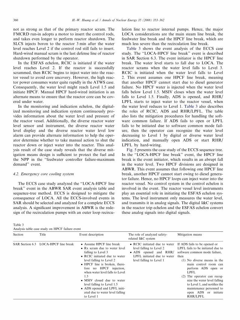
Fig. 5 presents the case study of the ECCS sequence tree.In the ‘‘LOCA-HPCF line break’’ event, the HPCF linebreak is the event initiator, which results in an abrupt fallin the water level. Two HPCF divisions are designed inABWR. This event assumes that following one HPCF linebreak, another HPCF cannot start owing to diesel genera-tor failure. Hence, no HPCF loops can inject water into thereactor vessel. No control system in the control echelon isinvolved in the event. The reactor vessel level instrumentsplay an essential role in initiating the ESFAS echelon sys-tems. The level instrument only measures the water level,and transmits it in analog signals. The digital I&C systemsin the reactor trip echelon and the ESFAS echelon convertthese analog signals into digital signals.
The role of analyzed safety-related I&C system
Mitigation means
vel
ter
re-n,
vel
ter
iti-ing
� RCIC initiated due to waterlevel falling to Level 2
� ADS opened and RHR/LPFL initiated due to waterlevel falling to Level 1
If ADS fails to be opened orLPFL fails to be initiated due tosoftware common mode failure,then
(1) No diverse means in themain control room canperform ADS open orLPFL
(2) The operator can recog-nize the water level fallingto Level 1, and notifies themaintenance personnel toopen ADS or initiateRHR/LPFL

Fig. 5. ECCS sequence tree case study.
H.-W. Huang et al. / Annals of Nuclear Energy 35 (2008) 353–362 361
362 H.-W. Huang et al. / Annals of Nuclear Energy 35 (2008) 353–362
In the reactor trip echelon, the reactor is scrammedwhen the water level reduces to Level 3. The MSIV isclosed when the water level reduces to Level 1.5. Since thiscase study concentrates on ECCS, it does not address soft-ware common mode failure in the reactor trip echelon. Ifthe RPS and ESFAS adopt the same operating system,then failure in the software common mode might defeatboth echelons simultaneously.
In the ESFAS echelon, RCIC is initiated if the waterlevel reaches Level 2. ADS is opened, and RHR/LPFL isinitiated to inject water to the reactor vessel when the waterlevel drops to Level 1. If software common mode failuredefeats the digital ADS or RHR/LPFL I&C system, thenthe operator should manually initiate the system by hard-wiring.
In the monitoring and indication echelon, the digitalizedmonitoring and indication system continuously providesreactor vessel water level and pressure information. Addi-tionally, the diverse reactor water level sensor and instru-ment, the diverse reactor water level display and thediverse reactor water level low alarm can provide alterna-tive information to notify the operator to initiate theADS or RHR/LPFL system by manual hard-wiring.
If automatic analog backup ADS and RHR/LPFL I&Csystems are adopted, then the operator’s work load andresponsibility can be shared when a software commonmode related event happens.
5. Conclusion
This study has successfully developed a system-levelsequence-tree-based PHA that can clarify the relation-ships among the major digital I&C systems. This sys-tem-centric technique cannot only identify preliminaryhazards, but also vulnerabilities in a nuclear power plant.Hence, inadequacies in the analog back-up systems orhard-wired manual initiation design can be improved,i.e., an effective simplified diversity and defense-in-depthevaluation can also be performed. Two case studies aredemonstrated in this paper, namely an RPS related caseand an ECCS related case to prove the feasibility of thismethod.
Manual action is the last line of defense in the all eche-lons in the NPP. If the D3 design includes sufficient auto-matic analog backups, then the operator’s working loadand responsibility can be properly shared when a softwarecommon mode related event occurs. Additionally, the USNRC established the position on D3 for the advanced reac-tors in the document BTP-19, noting that, ‘‘The diverse ordifferent function may be performed by a non-safety systemif the system is of sufficient quality to perform the necessaryfunction under the associated event conditions.’’ Thismeans that the utilities can adopt industrial grade analogI&C systems as the backups of digital system without beingsuffered by the safety grade regulatory process.
Acknowledgement
The authors thank Dr. Jong-Rong Wang, Li-HsinWang, Yuan-Chang Yu, Ben-Ching Liao of INER andWei-Yi Yang, Wan-Tsz Tu, Hung-Chih Hung, Shu-ChuanChen of NTHU for their technical assistance.
References
Branch Technical Position HICB-14, 1997. Guide on Software Review forDigital Computer-Based Instrumentation and Control System,USNRC, Washington, DC, USA.
Branch Technical Position HICB-19, 1997. Guidance for Evaluation ofDefense-in-Depth and Diversity in Digital Computer-Based Instru-mentation and Control Systems, USNRC, Washington, DC, USA.
Huang, H. et al., 2005. Development and Application of a SimulationFramework for Investigating Human Computer Interaction Process,19th Sino-Japanese Seminar on Nuclear Safety, Taipei, Taiwan.
Huang, H. et al., 2006a. Digital I&C Failure Events Derivation andAnalysis for ABWR, Dependability of Computer Systems 2006(DepCoS ’06), Szklarska Poreba, Poland.
Huang, H. et al., 2006b. Digital Instrumentation and Control FailureEvents Derivation and Analysis by Frame-Based Technique,ICONE14, Miami, Florida, USA.
Huang, H. et al., 2006c. Development of Evaluation Method for SoftwareSafety Analysis Techniques, 15PBNC, Sydney, 15–20 October 2006.
Huang, H. et al., 2006d. Development of Evaluation Method for SoftwareHazard Identification Techniques, 5th NPIC & HMIT, Albuquerque,NM, USA.
Huang, H. et al., 2007a. Model extension and improvement for simulator-based software safety analysis. Nuclear Engineering and Design 237,955–971.
Huang, H. et al., 2007b. Software failure events derivation and analysisby frame-based technique. Annals of Nuclear Energy 34, 307–318.
IEEE Std. 1044-1993, IEEE Standard Classification for SoftwareAnomalies.
IEEE Std. 1228-1994. IEEE Standard for Software Safety Plans.IEEE Std. 7-4.3.2-2003, IEEE Standard for Digital Computers in Safety
Systems of Nuclear Power Generating Stations.Lee, J. et al., 2001. Defense-in-depth and diversity evaluation to cope with
design bases events concurrent with common mode failure in digitalplant protection system for KNGR. Nuclear Engineering and Design207, 95–104.
Lee, J. et al., 2006. Evaluation of error detection coverage and fault-tolerance of digital plant protection system in nuclear power plants.Annals of Nuclear Energy 33 (6), 544–554.
Liu, J. et al., 2007. Safety analysis of software product lines using state-based modeling. Journal of Systems Software. doi:10.1016/j.jss.2007.01.04.
Micro-Simulation Technology, 2007. <http://www.microsimtech.com/>.NUREG/CR-6303, 1994. Method for Performing Diversity and Defense-
in-depth Analyses of Reactor Protection Systems.NUREG/CR-6430, 1995. Software Safety Hazard Analysis.Po, L.C., 1981. A faster than real-time computer code for loss of coolant
and feedwater transient prediction. ANS Transactions 39, 1056–1057.RELAP5-3D Home Page, 2007. <http://www.inl.gov/relap5/>.RETRAN-02, 2007a. <http://www.csai.com/retran/R02index.html>.RETRAN-3D, 2007b. <http://www.csai.com/retran/R3Dindex.html>.SECY 93-087, 1993. Defense against Common-Mode Failures in Digital
Instrumentation and Control System, Staff RequirementMemorandum.
Swu, Y. et al., 2004. Development and Application of Risk AnalysisTechniques for Digital I&C Systems, Nuclear Plant Instrumentation,Control and Human-Machine Interface Technologies NPIC & HMIT2000, Columbus, OH, USA.