system reliability for utility pv inverters · pdf filethe availability of a pv plant is...
TRANSCRIPT
System Reliability for Utility PV Inverters
Ron Vidano
February 26, 2014
Abstract
2 2/27/2014
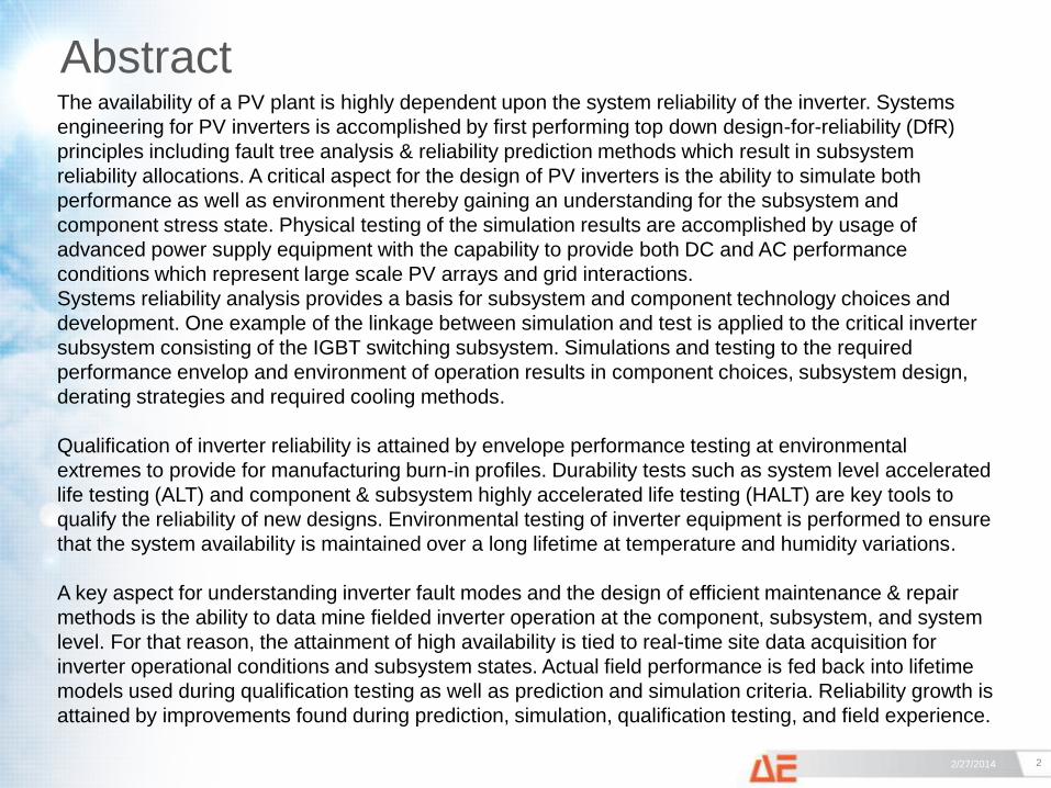
The availability of a PV plant is highly dependent upon the system reliability of the inverter. Systems
engineering for PV inverters is accomplished by first performing top down design-for-reliability (DfR)
principles including fault tree analysis & reliability prediction methods which result in subsystem
reliability allocations. A critical aspect for the design of PV inverters is the ability to simulate both
performance as well as environment thereby gaining an understanding for the subsystem and
component stress state. Physical testing of the simulation results are accomplished by usage of
advanced power supply equipment with the capability to provide both DC and AC performance
conditions which represent large scale PV arrays and grid interactions.
Systems reliability analysis provides a basis for subsystem and component technology choices and
development. One example of the linkage between simulation and test is applied to the critical inverter
subsystem consisting of the IGBT switching subsystem. Simulations and testing to the required
performance envelop and environment of operation results in component choices, subsystem design,
derating strategies and required cooling methods.
Qualification of inverter reliability is attained by envelope performance testing at environmental
extremes to provide for manufacturing burn-in profiles. Durability tests such as system level accelerated
life testing (ALT) and component & subsystem highly accelerated life testing (HALT) are key tools to
qualify the reliability of new designs. Environmental testing of inverter equipment is performed to ensure
that the system availability is maintained over a long lifetime at temperature and humidity variations.
A key aspect for understanding inverter fault modes and the design of efficient maintenance & repair
methods is the ability to data mine fielded inverter operation at the component, subsystem, and system
level. For that reason, the attainment of high availability is tied to real-time site data acquisition for
inverter operational conditions and subsystem states. Actual field performance is fed back into lifetime
models used during qualification testing as well as prediction and simulation criteria. Reliability growth is
attained by improvements found during prediction, simulation, qualification testing, and field experience.
Methodology - Reliability Assurance Milestones During Inverter Product Lifecycle
3 2/27/2014
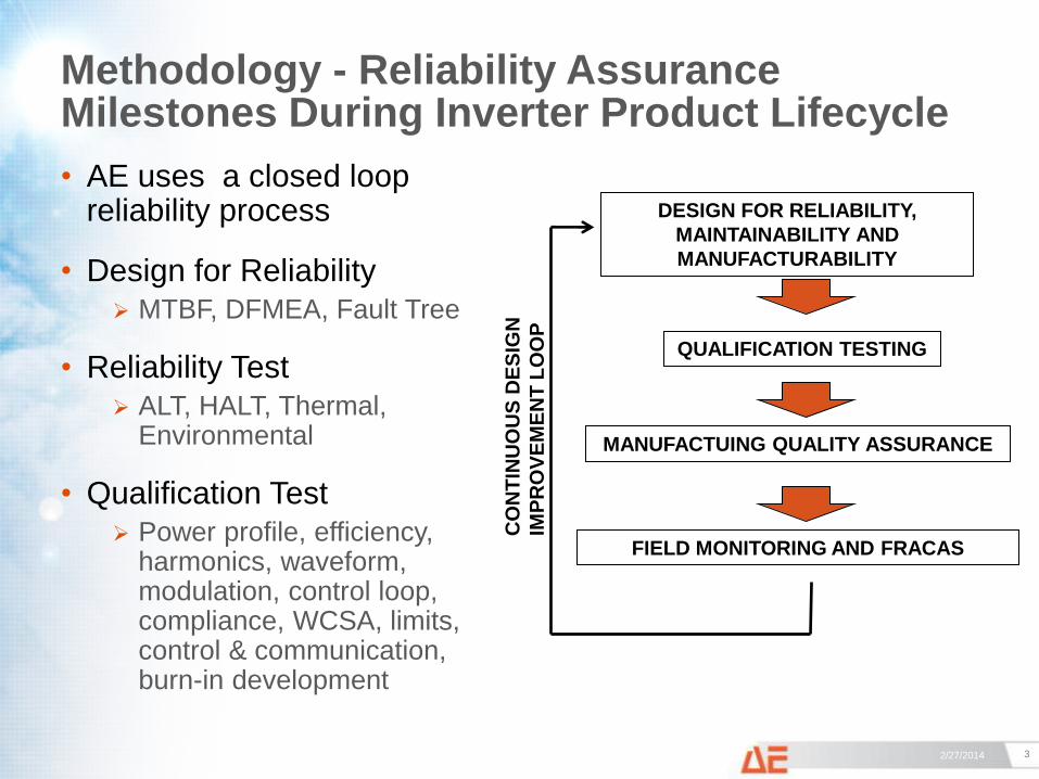
• AE uses a closed loop reliability process
• Design for Reliability
MTBF, DFMEA, Fault Tree
• Reliability Test
ALT, HALT, Thermal, Environmental
• Qualification Test
Power profile, efficiency, harmonics, waveform, modulation, control loop, compliance, WCSA, limits, control & communication, burn-in development
DESIGN FOR RELIABILITY,
MAINTAINABILITY AND
MANUFACTURABILITY
QUALIFICATION TESTING
FIELD MONITORING AND FRACAS
MANUFACTUING QUALITY ASSURANCE
CO
NT
INU
OU
S D
ES
IGN
IMP
RO
VE
ME
NT
LO
OP
Inverter Reliability Assurance Program
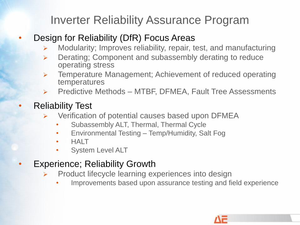
• Design for Reliability (DfR) Focus Areas Modularity; Improves reliability, repair, test, and manufacturing
Derating; Component and subassembly derating to reduce operating stress
Temperature Management; Achievement of reduced operating temperatures
Predictive Methods – MTBF, DFMEA, Fault Tree Assessments
• Reliability Test Verification of potential causes based upon DFMEA
• Subassembly ALT, Thermal, Thermal Cycle
• Environmental Testing – Temp/Humidity, Salt Fog
• HALT
• System Level ALT
• Experience; Reliability Growth Product lifecycle learning experiences into design
• Improvements based upon assurance testing and field experience
Design-for-Reliability; Reliability Calculation
5 2/27/2014
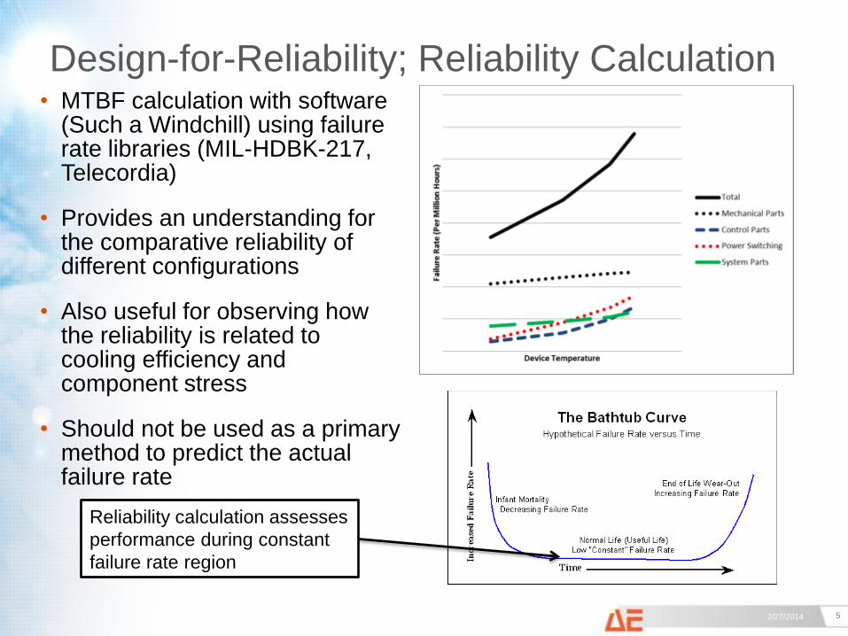
• MTBF calculation with software (Such a Windchill) using failure rate libraries (MIL-HDBK-217, Telecordia)
• Provides an understanding for the comparative reliability of different configurations
• Also useful for observing how the reliability is related to cooling efficiency and component stress
• Should not be used as a primary method to predict the actual failure rate
Reliability calculation assesses
performance during constant
failure rate region
Design-for-Reliability; DFMEA Example
6 2/27/2014
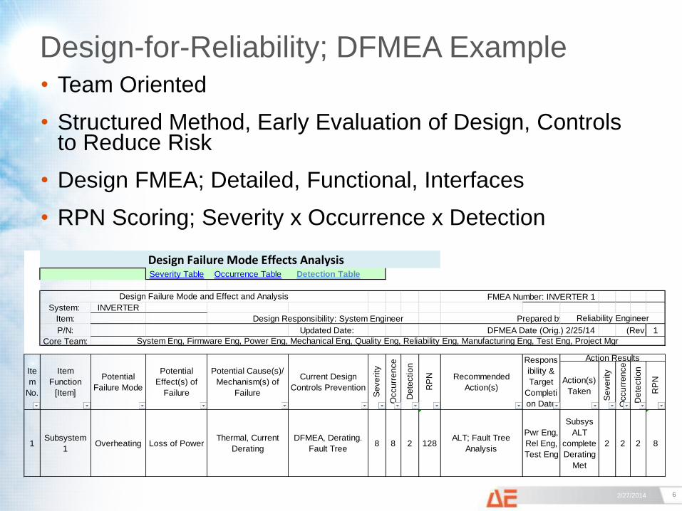
• Team Oriented
• Structured Method, Early Evaluation of Design, Controls to Reduce Risk
• Design FMEA; Detailed, Functional, Interfaces
• RPN Scoring; Severity x Occurrence x Detection
Design Failure Mode Effects Analysis Severity Table Occurrence Table Detection Table
FMEA Number: INVERTER 1
System: INVERTER
Item: Design Responsibility: System Engineer Prepared by:
P/N: Updated Date: DFMEA Date (Orig.) 2/25/14 (Rev.) 1
Core Team:
Action(s)
Taken
Se
ve
rity
Occu
rre
nce
De
tectio
n
RP
N
1Subsystem
1Overheating Loss of Power
Thermal, Current
Derating
DFMEA, Derating.
Fault Tree8 8 2 128
ALT; Fault Tree
Analysis
Pwr Eng,
Rel Eng,
Test Eng
Subsys
ALT
complete
Derating
Met
2 2 2 8
Reliability Engineer
System Eng, Firmware Eng, Power Eng, Mechanical Eng, Quality Eng, Reliability Eng, Manufacturing Eng, Test Eng, Project Mgr
Design Failure Mode and Effect and Analysis
Se
ve
rity
Occu
rre
nce Action Results
De
tectio
n
RP
N Recommended
Action(s)
Respons
ibility &
Target
Completi
on Date
Current Design
Controls Prevention
Ite
m
No.
Item
Function
[Item]
Potential
Failure Mode
Potential
Effect(s) of
Failure
Potential Cause(s)/
Mechanism(s) of
Failure
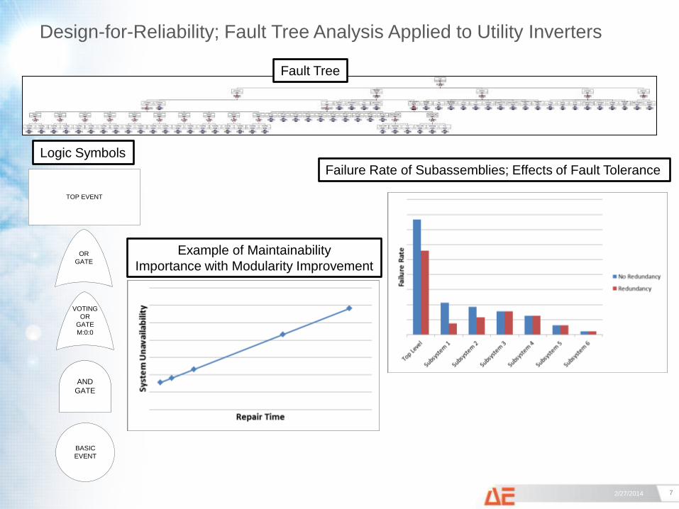
Design-for-Reliability; Fault Tree Analysis Applied to Utility Inverters
7 2/27/2014
Failure Rate of Subassemblies; Effects of Fault Tolerance
Example of Maintainability
Importance with Modularity Improvement
TOP EVENT
OR
GATE
AND
GATE
BASIC
EVENT
VOTING
OR
GATE
M:0:0
Logic Symbols
Fault Tree
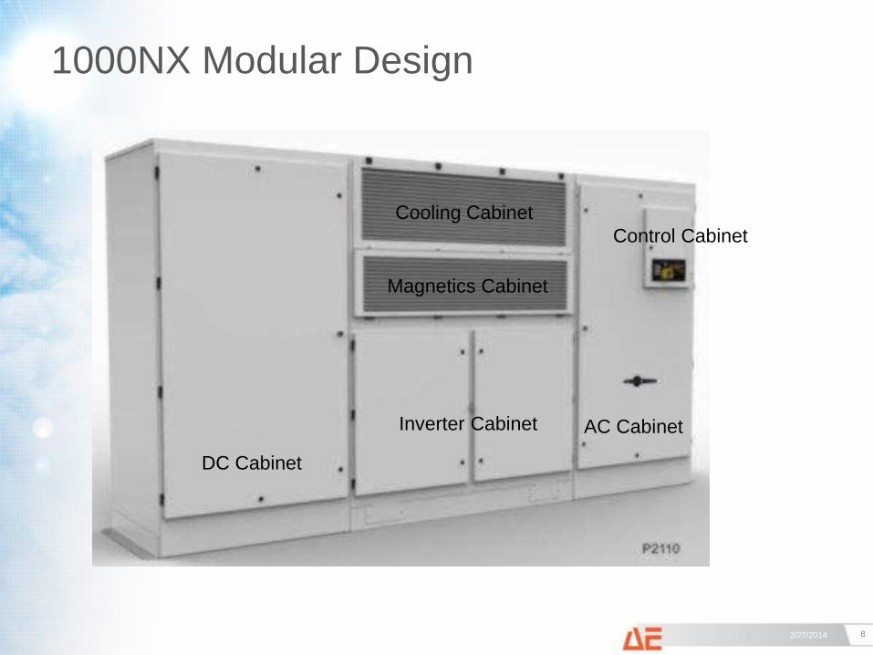
1000NX Modular Design
8 2/27/2014
DC Cabinet
AC Cabinet Inverter Cabinet
Magnetics Cabinet
Cooling Cabinet
Control Cabinet
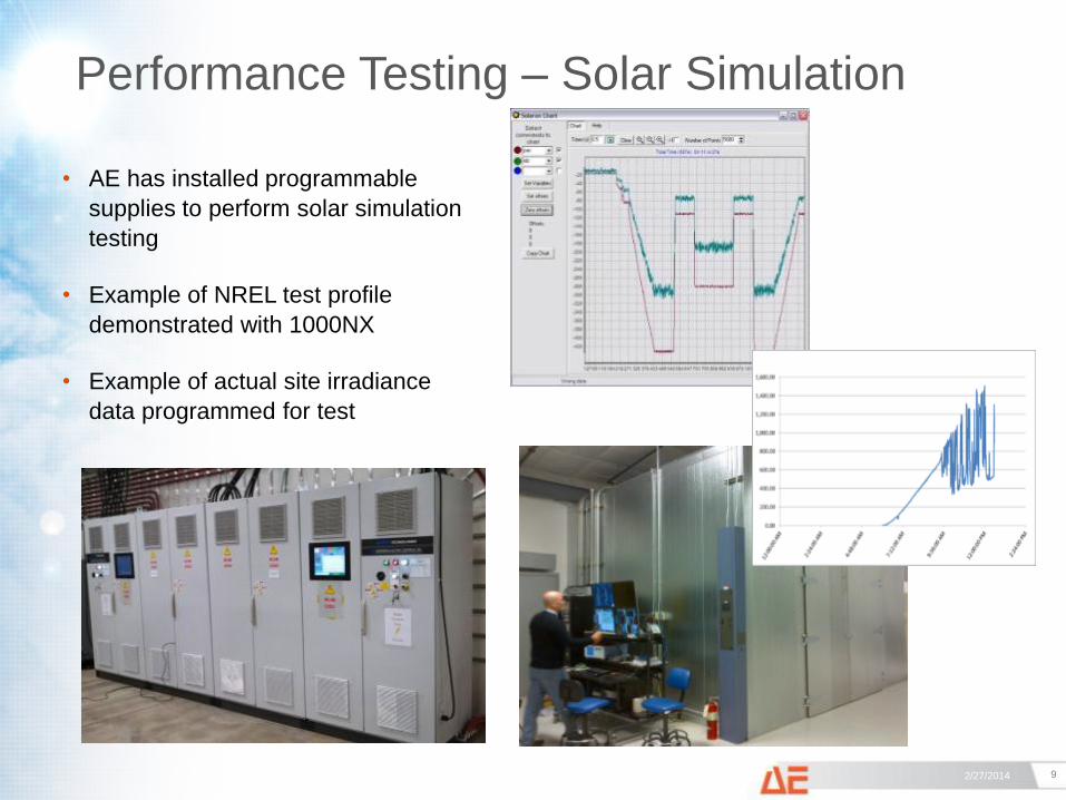
Performance Testing – Solar Simulation
9 2/27/2014
• AE has installed programmable
supplies to perform solar simulation
testing
• Example of NREL test profile
demonstrated with 1000NX
• Example of actual site irradiance
data programmed for test
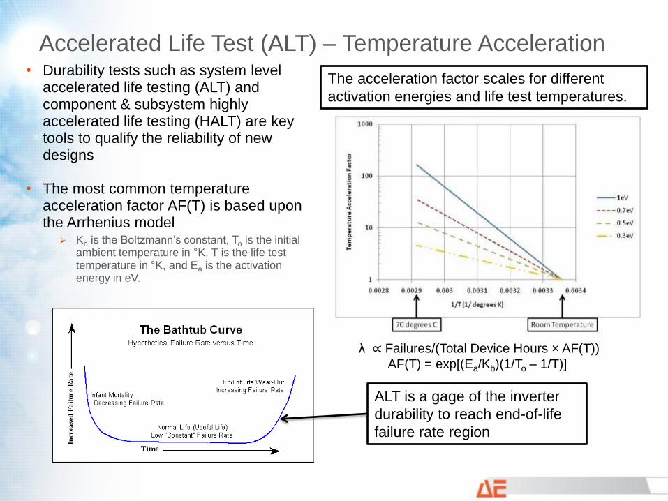
Accelerated Life Test (ALT) – Temperature Acceleration • Durability tests such as system level
accelerated life testing (ALT) and component & subsystem highly accelerated life testing (HALT) are key tools to qualify the reliability of new designs
• The most common temperature acceleration factor AF(T) is based upon the Arrhenius model
Kb is the Boltzmann’s constant, To is the initial ambient temperature in °K, T is the life test temperature in °K, and Ea is the activation energy in eV.
λ ∝ Failures/(Total Device Hours × AF(T))
AF(T) = exp[(Ea/Kb)(1/To – 1/T)]
ALT is a gage of the inverter
durability to reach end-of-life
failure rate region
The acceleration factor scales for different
activation energies and life test temperatures.
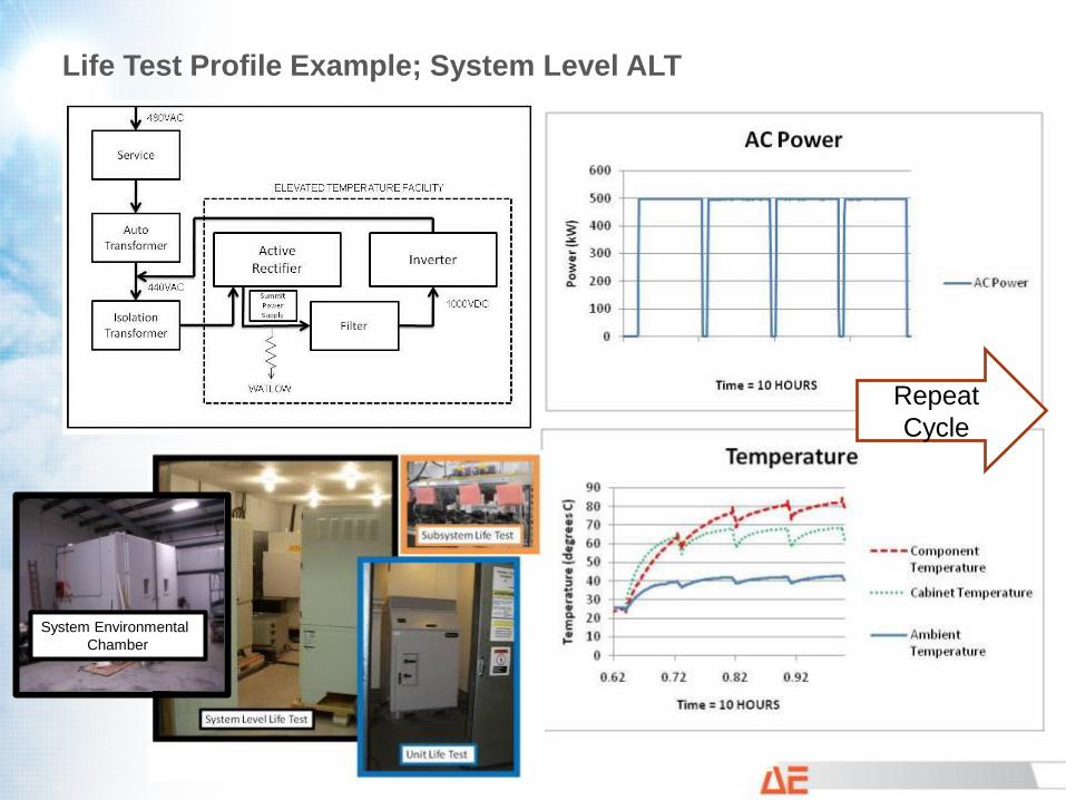
Life Test Profile Example; System Level ALT
Repeat
Cycle
System Environmental
Chamber
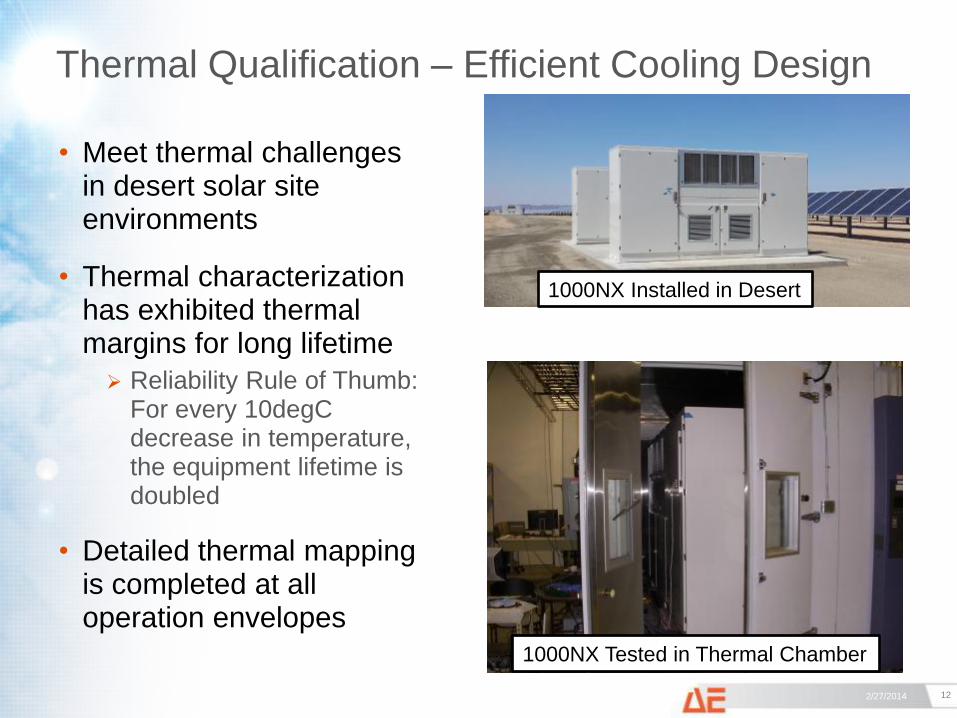
Thermal Qualification – Efficient Cooling Design
12 2/27/2014
• Meet thermal challenges in desert solar site environments
• Thermal characterization has exhibited thermal margins for long lifetime
Reliability Rule of Thumb: For every 10degC decrease in temperature, the equipment lifetime is doubled
• Detailed thermal mapping is completed at all operation envelopes
1000NX Installed in Desert
1000NX Tested in Thermal Chamber
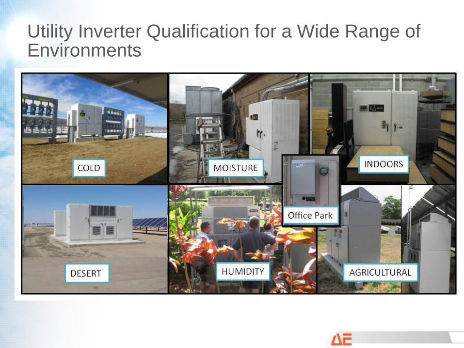
Utility Inverter Qualification for a Wide Range of Environments
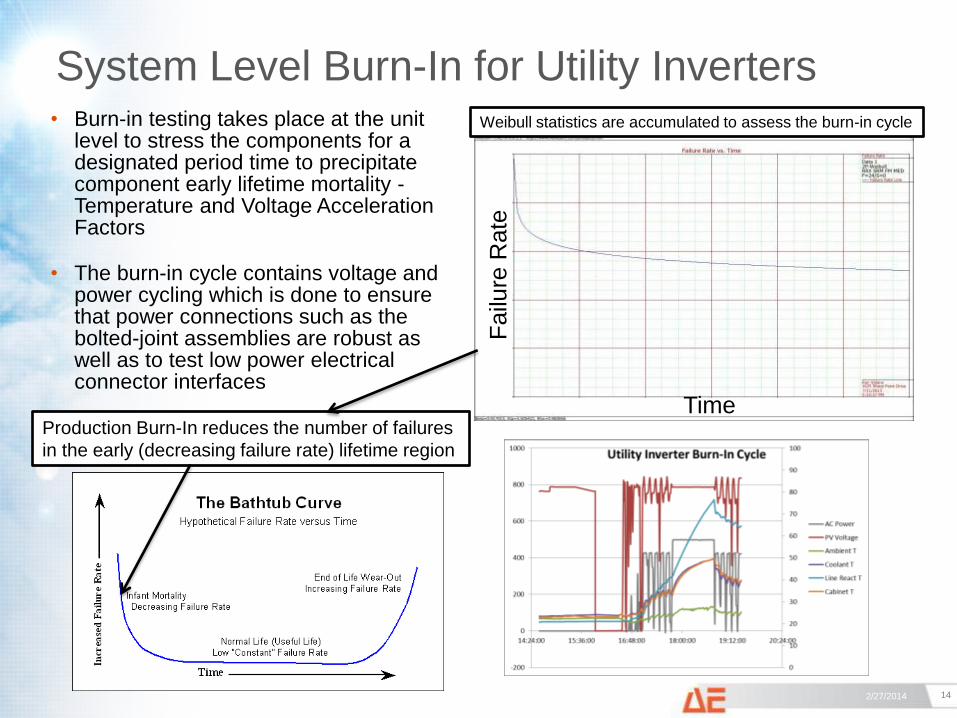
System Level Burn-In for Utility Inverters
14 2/27/2014
• Burn-in testing takes place at the unit level to stress the components for a designated period time to precipitate component early lifetime mortality - Temperature and Voltage Acceleration Factors
• The burn-in cycle contains voltage and power cycling which is done to ensure that power connections such as the bolted-joint assemblies are robust as well as to test low power electrical connector interfaces
Time
Failu
re R
ate
Production Burn-In reduces the number of failures
in the early (decreasing failure rate) lifetime region
Weibull statistics are accumulated to assess the burn-in cycle
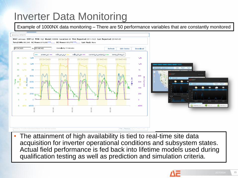
Inverter Data Monitoring
15 2/27/2014
• The attainment of high availability is tied to real-time site data acquisition for inverter operational conditions and subsystem states. Actual field performance is fed back into lifetime models used during qualification testing as well as prediction and simulation criteria.
Example of 1000NX data monitoring – There are 50 performance variables that are constantly monitored
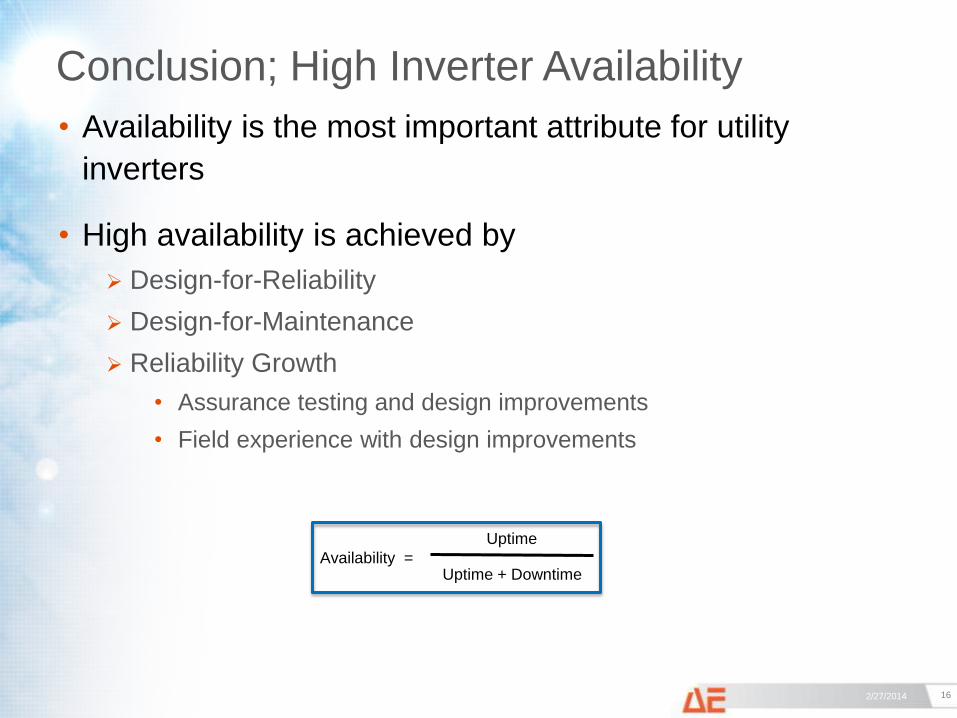
Conclusion; High Inverter Availability
16 2/27/2014
• Availability is the most important attribute for utility
inverters
• High availability is achieved by
Design-for-Reliability
Design-for-Maintenance
Reliability Growth
• Assurance testing and design improvements
• Field experience with design improvements
Availability =
Uptime
Uptime + Downtime
AE Solar Energy 115 Nicholson Lane
San Jose, CA. 95134
(541) 312-3832
(877) 312-3832
www.advanced-energy.com/solarenergy