system saver 636 twin cylinder air compressor for mack e ... - wabco … · service notes service...
TRANSCRIPT

System Saver 636 TwinCylinder Air Compressorfor Mack E-TechTM Engines
Maintenance Manual MM-0204Issued 08-02

Service Notes
Service NotesService NotesService Notes
Before You Begin
This manual provides service and repair procedures for the Meritor WABCO System Saver 636 twin cylinder air compressor for Mack E-Tech
TM
engines. Before you begin procedures:
1. Read and understand all instructions and procedures before you begin to service components.
2. Read and observe all Caution and Warning safety alerts that precede instructions or procedures you will perform. These alerts help to avoid damage to components, serious personal injury, or both.
3. Follow your company’s maintenance and service, installation, and diagnostics guidelines.
4. Use special tools when required to help avoid serious personal injury and damage to components.
Safety Alerts, Torque Symbol and Notes
Access Product and Service Information on Our Website
Enter meritorwabco.com in your browser’s address box for quick access to our website. At our home page, click on literature to access our publications.
meritorwabco.com
To Order Information by Phone
Call ArvinMeritor’s Customer Service Center at 800-535-5560 to order the following item.
O
Drivetrain Plus
TM
by ArvinMeritor Technical Electronic Library on CD. Features product and service information on most Meritor, ZF Meritor and Meritor WABCO products. $20. Order TP-9853.
WARNING
A Warning alerts you to an instruction or procedure that you must follow exactly to avoid serious personal injury.
CAUTION
A Caution alerts you to an instruction or procedure that you must follow exactly to avoid damage to components.
A torque symbol alerts you to tighten fasteners to a specified torque value.
NOTE
A Note provides information or suggestions that help you correctly service a component.

Table of Contents
Section 1: Introduction
Application . . . . . . . . . . . . . . . . . . . . . . . . . . . . . . . . . . . . . . . . . . . . . . . . . . . . . . . . . . . . . . . . . . . . . . . . . . .1Description Operation . . . . . . . . . . . . . . . . . . . . . . . . . . . . . . . . . . . . . . . . . . . . . . . . . . . . . . . . . . . . . . . . . . . . . . . . . . . .2Maintenance Intervals Cylinder Head Visual Inspection . . . . . . . . . . . . . . . . . . . . . . . . . . . . . . . . . . . . . . . . . . . . . . . . . . . . . . . . . . . . . . . . . . . . . .3
Section 2: Troubleshooting
. . . . . . . . . . . . . . . . . . . . . . . . . . . . . . . . . . . . . . . . . . . . . . . . . . . . . . . . . . . .5
Section 3: Compressor Replacement
Compressor Replacement Information . . . . . . . . . . . . . . . . . . . . . . . . . . . . . . . . . . . . . . . . . . . . . . . . . . . .9Compressor Removal Compressor Installation . . . . . . . . . . . . . . . . . . . . . . . . . . . . . . . . . . . . . . . . . . . . . . . . . . . . . . . . . . . . . . .10Cylinder Head Replacement Removal Installation . . . . . . . . . . . . . . . . . . . . . . . . . . . . . . . . . . . . . . . . . . . . . . . . . . . . . . . . . . . . . . . . . . . . . . . . . .11Performance Testing . . . . . . . . . . . . . . . . . . . . . . . . . . . . . . . . . . . . . . . . . . . . . . . . . . . . . . . . . . . . . . . . . .13Air System Leakage Test
Section 1Introduction
Maintenance Manual MM-0204 Copyright 2002Issued 08-02 ArvinMeritor, Inc. Page 1
Section 1Introduction
Application
O
Used on Mack engines.
Figure 1.1
.
O
Swept volume displacement: 37.4 cubic feet per minute.
O
Flange mounted to the engine.
— Coupling driven through the auxiliary shaft.
— Inlet air, oil lubrication and coolant supplied from the engine.
O
Pneumatic pressure signal from the governor controls compression:
— Integrated pressure relief valve protects the compressor and engine if discharge or governor lines become blocked, or if compressor cannot unload. The valve prevents the compressor from pumping more than 250 psi in the event of a blocked discharge line or other malfunction.
NOTE:
This compressor has NO through drive capabilities for hydraulic power steering pumps.
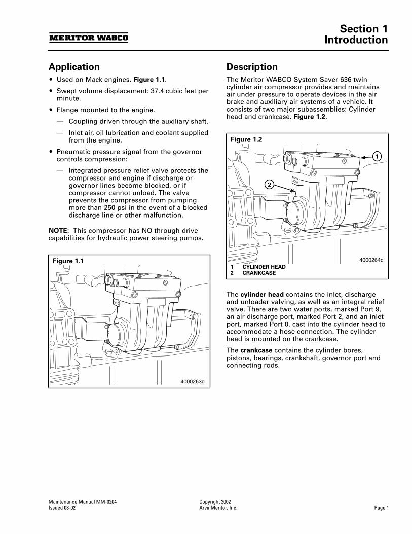
Description
The Meritor WABCO System Saver 636 twin cylinder air compressor provides and maintains air under pressure to operate devices in the air brake and auxiliary air systems of a vehicle. It consists of two major subassemblies: Cylinder head and crankcase.
Figure 1.2
.
The
cylinder head
contains the inlet, discharge and unloader valving, as well as an integral relief valve. There are two water ports, marked Port 9, an air discharge port, marked Port 2, and an inlet port, marked Port 0, cast into the cylinder head to accommodate a hose connection. The cylinder head is mounted on the crankcase.
The
crankcase
contains the cylinder bores, pistons, bearings, crankshaft, governor port and connecting rods.
Figure 1.1
4000263d
Figure 1.2
1 CYLINDER HEAD2 CRANKCASE
4000264d
1
2

Section 1Introduction
Copyright 2002 Maintenance Manual MM-0204Page 2 ArvinMeritor, Inc. Issued 08-02
Operation
The compressor is driven by the engine. The compressor’s crankshaft turns continuously while the engine is running. Compression of air is controlled by the
governor
and by the
compressor’s unloading mechanisms
.
The
governor
maintains the brake system air pressure at preset maximum and minimum levels. The governor is mounted apart from the compressor, either horizontally or vertically. The governor port is located on the crankcase of the compressor.
Figure 1.3
.
The
unloader mechanisms
control the air compression cycle; an air compression cycle has three phases:
1.
Induction:
Air flows from the engine to the compressor, opening the inlet valves in the cylinder head of the compressor.
2.
Compression:
Air pressure is increased, causing the compressor’s discharge valves to open.
3.
Unloading:
Air passes from the cylinders to the inlet chambers of the cylinder head via a port controlled by sliding leaf valves.
When system cut-in pressure is reached, air is exhausted from the unloader ports.
4. After unloading, the unloader pistons return the sliding leaf valves to the loaded position. This seals the unloader ports and compression resumes.
Figure 1.4
.
Maintenance Intervals
The Meritor WABCO System Saver 636 twin cylinder air compressor receives inlet air, oil and coolant from the engine, so it is important to follow the engine manufacturer’s recommendations and maintenance schedules regarding fluid levels, air filter and recommended change intervals.
Cylinder Head
Remove carbon deposits from the discharge cavity and rust and scale from the cooling passages of the cylinder head.
Clean carbon and dirt from the inlet and unloader passages.
Figure 1.3
1 GOVERNOR PORT
4000265b
1
Figure 1.4
1 SLIDING LEAF VALVES
4000266c
11

Section 1Introduction
Maintenance Manual MM-0204 Copyright 2002Issued 08-02 ArvinMeritor, Inc. Page 3
Visual Inspection
A visual check of the compressor can detect minor problems (see legend for examples of these problems). This check should be part of the vehicle preventive maintenance program.
Figure 1.5
.
Figure 1.5
1 Check water ports for leakage.2 Check air inlet and discharge ports for leakage.3 Check around end cover for oil leakage.4 Check flanges for cracks or breaks.
4000267c
21
3
4

Notes
Copyright 2002 Maintenance Manual MM-0204Page 4 ArvinMeritor, Inc. Issued 08-02

Section 2Troubleshooting
Maintenance Manual MM-0204 Copyright 2002Issued 08-02 ArvinMeritor, Inc. Page 5
Section 2Troubleshooting
Use the following chart to troubleshoot the Meritor WABCO System Saver 636 twin cylinder air compressor.
NOTE:
If you have any questions or need additional information, please contact the Meritor WABCO Customer Service Center at 866-668-7221.
Table A: Compressor Troubleshooting Guide
Condition Possible Cause Solution
Compressor passes excessive oil
(for example, the presence of oil at exhaust air brake system valves, oil in air dryer dessicant, etc.)
Blocked or restricted oil return Clean oil drain passages in the compressor and on the engine surface. Verify proper passage alignment.
Contaminated inlet air or oil Replace damaged, defective or dirty engine air filter.
Repair any leaking, damaged or defective compressor air intake components.
Change engine lubricating oil.
NOTE:
To avoid this condition, make sure vehicle manufacturer’s oil and filter maintenance schedules are followed.
Restricted air inlet or excessive vacuum present at compressor inlet
Verify engine air cleaner is functioning properly. Replace if necessary.
Repair compressor air inlet kinks or excessive bends.
Check vehicle specifications to ensure air and coolant lines meet all requirements.
Excessive engine crankcase pressure
Verify engine crankcase venting is to manufacturer’s specification.
Compressor duty cycle too high Check system for leaks. Make necessary repairs.
None of the above, but condition persists
Replace the compressor.
Compressor leaks oil
Physical damage or internal problems with compressor
Replace the compressor.
Compressor continuously cycles
Compressor unloader piston leaking
With compressor unloaded check for air leakage. If leaking, replace the cylinder head.
Governor air leak Refer to the manufacturer’s manual for governor maintenance and troubleshooting procedures.
Dryer purge valve air leakage Check for air dryer malfunction. Refer to air dryer manufacturer’s service instructions.
Air leak at governor-compressor attachment.
Inspect connection for physical damage. Inspect and repair connection.
Air leak at alcohol injector Clear line of any obstructions.
Inspect and repair connection.
Excessive reservoir contamination
Drain reservoirs.
None of the above, but condition persists
Replace the compressor.

Section 2Troubleshooting
Copyright 2002 Maintenance Manual MM-0204Page 6 ArvinMeritor, Inc. Issued 08-02
No air delivery
Low air delivery
Low air pressure
Discharge line blockage Check for freeze up in the discharge line.
Check low spots and eliminate any traps in the discharge line.
Inspect and repair compressor discharge port and clear any line restrictions. Replace damaged lines as necessary.
Check for carbon build-up. If carbon has built up, make sure cooling lines are not kinked or restricted. If carbon has built up in the discharge line, replace the line.
Inlet line kinked or restricted Inspect the compressor air induction line for kinks and restrictions. Repair or replace as necessary.
Governor malfunction or misadjustment
Check for proper loader/unloader cycles of compressor.
Refer to vehicle manufacturer’s manual for governor maintenance and troubleshooting procedures.
External contamination Replace broken, defective or dirty air filters. Clean contaminants from surface of compressor.
Air dryer purge valve stuck open or leaking
Check for air dryer malfunction. Refer to air dryer manufacturer’s service instructions.
Chafed or worn discharge line Replace faulty sections of discharge line.
Loose or leaking air line connections
Verify all connections are secure.
Tighten to vehicle specifications where necessary.
Inspect port threads for damage. If damage is extensive, replace cylinder head.
Damage to compressor valves and/or valve seats
Replace the cylinder head.
Leaking or malfunctioning internal pressure relief valve
Replace the cylinder head.
Noisy air compressor
Loose drive hub
Loose accessory drive coupling
Check fit of drive coupling.
Ensure hub is completely seated and crankshaft nut is tight.
Inspect crankshaft for damage — replace compressor if crankshaft is damaged.
None of the above, but condition persists
Replace the compressor.
Broken connecting rod or crankshaft
Oil starvation to crank pin or front main bearing
Check oil pressure. Verify oil passage is free of obstructions. Make necessary repairs.
Failed power steering pump Verify power steering pump is in proper operating order. Refer to the component manufacturer’s service instructions.
All of the above Replace compressor.
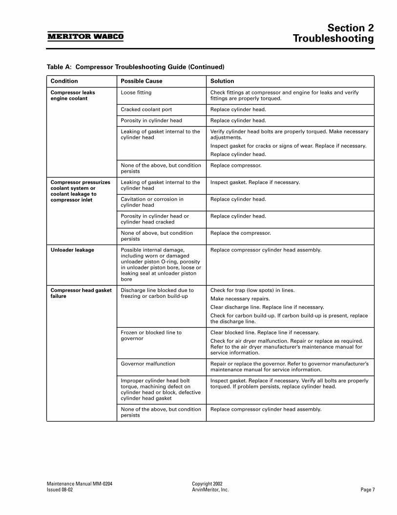
Table A: Compressor Troubleshooting Guide (Continued)
Condition Possible Cause Solution
Section 2Troubleshooting
Maintenance Manual MM-0204 Copyright 2002Issued 08-02 ArvinMeritor, Inc. Page 7
Compressor leaks engine coolant
Loose fitting Check fittings at compressor and engine for leaks and verify fittings are properly torqued.
Cracked coolant port Replace cylinder head.
Porosity in cylinder head Replace cylinder head.
Leaking of gasket internal to the cylinder head
Verify cylinder head bolts are properly torqued. Make necessary adjustments.
Inspect gasket for cracks or signs of wear. Replace if necessary.
Replace cylinder head.
None of the above, but condition persists
Replace compressor.
Compressor pressurizes coolant system or coolant leakage to compressor inlet
Leaking of gasket internal to the cylinder head
Inspect gasket. Replace if necessary.
Cavitation or corrosion in cylinder head
Replace cylinder head.
Porosity in cylinder head or cylinder head cracked
Replace cylinder head.
None of above, but condition persists
Replace the compressor.
Unloader leakage
Possible internal damage, including worn or damaged unloader piston O-ring, porosity in unloader piston bore, loose or leaking seal at unloader piston bore
Replace compressor cylinder head assembly.
Compressor head gasket failure
Discharge line blocked due to freezing or carbon build-up
Check for trap (low spots) in lines.
Make necessary repairs.
Clear discharge line. Replace line if necessary.
Check for carbon build-up. If carbon build-up is present, replace the discharge line.
Frozen or blocked line to governor
Clear blocked line. Replace line if necessary.
Check for air dryer malfunction. Repair or replace as required. Refer to the air dryer manufacturer’s maintenance manual for service information.
Governor malfunction Repair or replace the governor. Refer to governor manufacturer’s maintenance manual for service information.
Improper cylinder head bolt torque, machining defect on cylinder head or block, defective cylinder head gasket
Inspect gasket. Replace if necessary. Verify all bolts are properly torqued. If problem persists, replace cylinder head.
None of the above, but condition persists
Replace compressor cylinder head assembly.
Table A: Compressor Troubleshooting Guide (Continued)
Condition Possible Cause Solution

Notes
Copyright 2002 Maintenance Manual MM-0204Page 8 ArvinMeritor, Inc. Issued 08-02

Section 3Compressor Replacement
Maintenance Manual MM-0204 Copyright 2002Issued 08-02 ArvinMeritor, Inc. Page 9
Section 3Compressor Replacement
The cylinder head portion of the compressor is replaceable. The crankcase is not replaceable. If the crankcase is damaged or malfunctioning, replace the complete compressor.
WARNING
To prevent serious eye injury, always wear safe eye protection when you perform vehicle maintenance or service.
Remove all pressure from the air system before you disconnect any component. Pressurized air can cause serious personal injury.
Park the vehicle on a level surface. Block the wheels to prevent the vehicle from moving. Support the vehicle with safety stands. Do not work under a vehicle supported only by jacks. Jacks can slip and fall over. Serious personal injury and damage to components can result.
Compressor Replacement Information
CAUTION
The removal instructions given in this manual are general. Depending on the type of vehicle involved, additional steps may be required. Refer to the vehicle manufacturer’s manual for additional information.
The front of the Meritor WABCO System Saver 636 air compressor is mounted to the engine.
Before you remove the compressor, make sure you have a replacement gasket to install with the new compressor (Mack Part Number 590GB2159). Figure 3.1.
Compressor Removal
1. Set the spring (parking) brakes and block the wheels of the vehicle.
2. Drain the air pressure from the air system.
3. Drain the engine cooling system and the cylinder head of the compressor.
4. Disconnect all air and water lines leading to the compressor.
5. Remove the discharge and coolant fittings. Note fitting locations to aid in reassembly.
NOTE:
The discharge fitting consists of a fitting and a bushing. The bushing should remain in the cylinder head.
6. Loosen and remove the four bracket mounting bolts: Two bolts that hold the rear support bracket to the back of the compressor and two bolts that hold the bracket to the engine block. Retain the bolts for re-assembly.
NOTE:
This bracket supports the weight of the compressor.
7. Loosen the three flange mounting bolts that hold the compressor to the engine.
8. Remove the compressor from the engine.
Remove and retain the oil supply tube that runs between the compressor and the engine. Figure 3.2.
Figure 3.1
1003382a1003382a

Section 3Compressor Replacement
Copyright 2002 Maintenance Manual MM-0204Page 10 ArvinMeritor, Inc. Issued 08-02
Compressor Installation
1. Reinstall the oil supply tube.
2. Install a new compressor gasket.
3. Position the compressor on the engine.
4. Install the three flange mounting bolts. Tighten to 15 lb-ft (20 N•m) +90° rotation.
5. Install the two bolts that hold the bracket to the compressor and the two bolts that hold the bracket to the engine block. Run the bolts down finger tight at both ends of the bracket (engine and compressor). The bracket should be in contact with both surfaces; engine block and compressor rear support face. Tighten bolts to 18 lb-ft (25 N•m) maximum at compressor side. Tighten bolts at engine side per Mack specification.
6. Attach the discharge and coolant fittings. Finger-tighten fittings and rotate 2 to 3 turns to position fitting.
7. Connect all air and water lines leading to the compressor. Tighten per Mack specifications.
8. Add engine coolant to the cooling system. Use the coolant recommended by the engine manufacturer. Visually inspect the engine and compressor for leaks.
9. Start the engine and allow air system to build to governor cutout. Stop the engine. Use a soap and water solution at connection points to check for air leaks. Make any necessary repairs.
10. Remove the wheel blocks and release the spring (parking) brakes.
Cylinder Head Replacement
Removal
1. Follow the steps listed in Compressor Removal to remove the compressor from the engine. Take care not to damage the crankcase, since it will not be replaced.
2. Use a cleaning solvent to remove road dirt and grease from the exterior of the compressor.
3. Remove and discard the six hex head bolts that attach the cylinder head to the crankcase and remove the cylinder head valves and gaskets.
Figure 3.3
.
4. Use a mild cleaning solvent to clean the top of the crankcase.
Figure 3.2
1 OIL SUPPLY TUBE
4000263b
4000268d
1
Figure 3.3
4000269b

Section 3Compressor Replacement
Maintenance Manual MM-0204 Copyright 2002Issued 08-02 ArvinMeritor, Inc. Page 11
Installation
NOTE:
A Torx
®
tool is required for this procedure.
Cylinder head valve components MUST be aligned in the proper position in order for the compressor to function.
1. Install the sliding leafs. The two holes in each sliding leaf must be installed over the two pins on the base of the cylinder head.
Figure 3.4
.
NOTE:
A light application of engine oil will hold the sliding leaves to the inlet valves.
Figure 3.4
.
2. Lay the new cylinder head gasket in place, ensuring that it fits over the guide bushings and that the unloader hole allows air pressure communication from the cylinder head to the crankcase.
Figure 3.5
.
3. Place the inlet valves over the guide pins provided, ensuring that the pads are up and the valves will lie flat against the head openings. A small amount of Lubriplate grease can be used to ensure they remain in place for the remainder of the assembly.
Figure 3.5
.
4. Position the cylinder head on top of the compressor. Ensure the notched pins on the cylinder head align with the recesses in the block. Only four of the six bolt holes have notched pins.
Figure 3.6
.
Figure 3.4
1 SLIDING LEAF VALVES2 UNLOADER PASSAGE3 GUIDE BUSHINGS
4000271c
1
1
2
3
Figure 3.5
1 INLET VALVE2 CYLINDER HEAD GASKET
Figure 3.6
1 CYLINDER HEAD NOTCHED PINS2 SIDE VIEW OF CYLINDER HEAD
2
1
4000273b
1 1
2

Section 3Compressor Replacement
Copyright 2002 Maintenance Manual MM-0204Page 12 ArvinMeritor, Inc. Issued 08-02
5. Install the six hex head mounting bolts that hold the cylinder head in place. Tighten the mounting bolts in sequence per Table B, following Steps 1-12.
Figure 3.7
.
6. Use a Torx
®
tool to tighten the seven Torx
®
head screws in sequence per Table B, following Steps 13-26.
Figure 3.8
.
CAUTION
Use the proper tools to perform this torque-turn bolt tightening sequence exactly as shown in Table B. Accuracy is CRITICAL to your field service success!
Table B: Bolt Tightening Sequence
7. Follow the steps listed in Compressor Installation to reinstall the compressor and test for leaks.
Figure 3.7
1 Tighten bolts in sequence shown.
Figure 3.8
1 Tighten bolts in sequence shown.
4000274b
1 A E
B
F
C
D
4000275b
1
I
K
J
H G
L M
Step Bolt
TorqueRotation (Degrees) (N•m) lb-ft
1 A 25
+0-5
18.5
+0-3.7
2 B 25
+0-5
18.5
+0-3.7
3 C 25
+0-5
18.5
+0-3.7
4 D 25
+0-5 18.5 +0
-3.7
5 E 25 +0-5 18.5 +0
-3.7
6 F 25 +0-5 18.5 +0
-3.7
7 A 150° +15-5
8 B 150° +15-5
9 C 120° +15-5
10 D 120° +15-5
11 E 120° +15-5
12 F 120° +15-5
13 G 6 +6-6 4.4 +4.4
-4.4
14 H 6 +6-6 4.4 +4.4
-4.4
15 I 6 +6-6 4.4 +4.4
-4.4
16 J 6 +6-6 4.4 +4.4
-4.4
17 K 6 +6-6 4.4 +4.4
-4.4
18 L 6 +6-6 4.4 +4.4
-4.4
19 M 6 +6-6 4.4 +4.4
-4.4
20 G 135° +15-5
21 H 135° +15-5
22 I 135° +15-5
23 J 135° +15-5
24 K 135° +15-5
25 L 135° +15-5
26 M 135° +15-5

Section 3Compressor Replacement
Maintenance Manual MM-0204 Copyright 2002Issued 08-02 ArvinMeritor, Inc. Page 13
Performance Testing
Test the vehicle air system as follows:
1. Bleed the vehicle air system reservoir gauges down (apply brakes several times) to approximately 85 psig.
2. With the engine running at full governed speed (no load, no air accessories being used), the compressor should reach governor cutout pressure, then unload.
If the compressor does not reach governor cutout pressure, check for air leaks in the system. If reservoir volume and engine RPM are per original vehicle manufacturer’s specifications, system plumbing leakage must be checked and, if necessary, repaired. See air system leakage test procedures which follow.
If the compressor fails to unload, verify proper governor operation.
Air System Leakage Test
(Conforms to North American Uniform Roadside Inspection Criteria)
1. Park the vehicle on a level surface. Apply the parking brakes. Disconnect any attached or towed vehicles (semi-trailer, full trailer, dolly, etc.). Leave engine on.
2. Chock the tires.
3. Release the parking brakes.
4. With the compressor in pumping mode, engine at idle and service brakes fully applied gauge must stay between 80-90 psi or gradually rise.
If pressure is not maintained (pressure drops) there is an air leak in the system.
Listen for air leaks. Soapy water or high frequency acoustic detectors may be used to detect any leaks. Make the necessary repairs.

Meritor WABCOVehicle Control Systems3331 West Big Beaver Road, Suite 300Troy, MI 48084 USA800-535-5560meritorwabco.com
Information contained in this publication was in effect at the time the publication was approved for printing and is subject to change without notice or liability. Meritor WABCO reserves the right to revise the information presented or discontinue the production of parts described at any time.
Copyright 2002 Maintenance Manual MM-0204ArvinMeritor, Inc. Issued 08-02All Rights Reserved Printed in the USA 16579/24240