system stability - pjm
TRANSCRIPT
PJM State & Member Training Dept.
System Stability
Transmission ITP
10/15/2019PJM©2019
Objectives
Students will be able to:
• Define:
‒ Stable operations
‒ Instability
‒ Steady State Stability
‒ Dynamic Stability
‒ Transient Stability
• Discuss the actions that may be taken by the System Operator that will impact the stability of the system
• Discuss how instability threatens the system
2
• Generic:
‒ Stability is the condition of equilibrium between opposing forces
• In the power system:
‒ Mechanical Power = Electrical Power
• Following a disturbance:
‒ Mechanical Power = Electrical Power + Acceleration Power
• Maximum amount of power that can be transferred without a loss of synchronism is defined as the power, or stability limit
‒ Critical value of power transfer
Stable Operation
6270 3
• Angular differences must exist between two buses in order for MW to flow
• If δ = 0, then PTransfer = 0
• δ is the driving force for MW flow
• δ can also indicate direction of MW flow
• MWs flow “downhill” with respect to δ
• Restated: Buses with high δ flow MW towards buses with lower δ
Transmission System MW Flow and Power Angle
(to a point)
(to a point)
6270 4
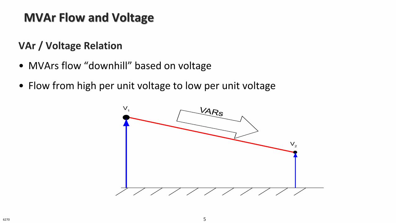
VAr / Voltage Relation
• MVArs flow “downhill” based on voltage
• Flow from high per unit voltage to low per unit voltage
MVAr Flow and Voltage
6270 5
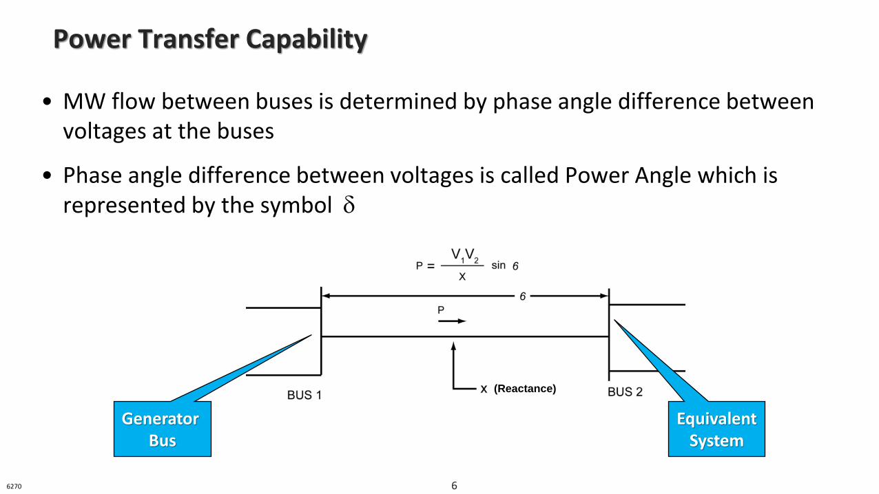
• MW flow between buses is determined by phase angle difference between voltages at the buses
• Phase angle difference between voltages is called Power Angle which is represented by the symbol
Power Transfer Capability
Generator Bus
EquivalentSystem
(Reactance)
6270 6
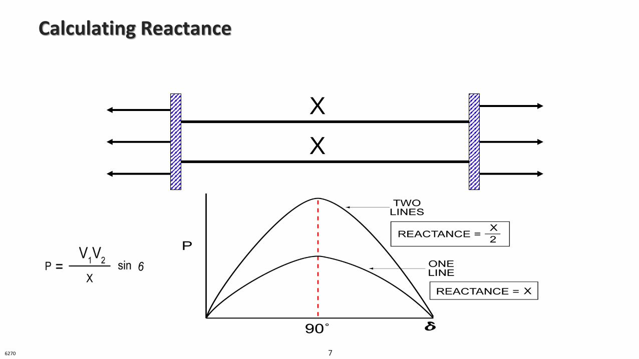
Calculating Reactance
X
X
6270 7
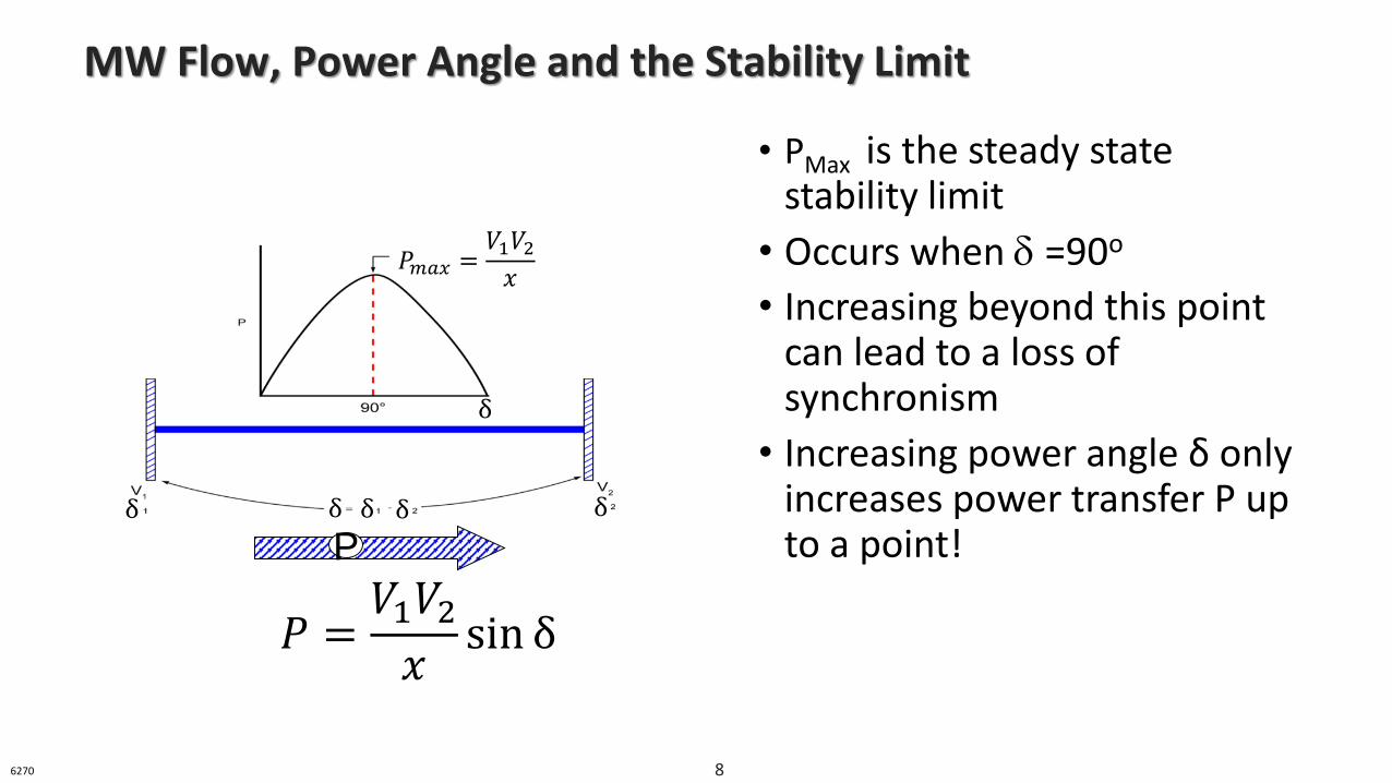
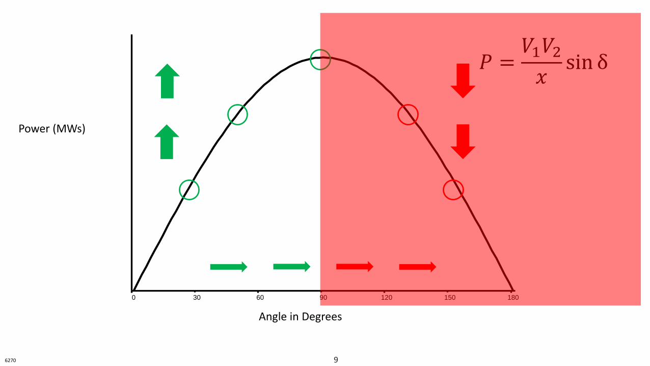
MW Flow, Power Angle and the Stability Limit
• PMax is the steady state stability limit
• Occurs when =90o
• Increasing beyond this point can lead to a loss of synchronism
• Increasing power angle δ only increases power transfer P up to a point!P
𝑃 =𝑉1𝑉2𝑥
sin δ
𝑃𝑚𝑎𝑥 =𝑉1𝑉2𝑥
δ
δδ δ δ δ
6270 8
Angle in Degrees
0 30 60 90 120 150 180
Power (MWs)
𝑃 =𝑉1𝑉2𝑥
sin δ
6270 9
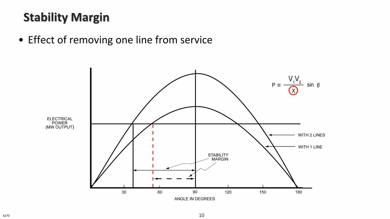
• Effect of removing one line from service
Stability Margin
6270 10
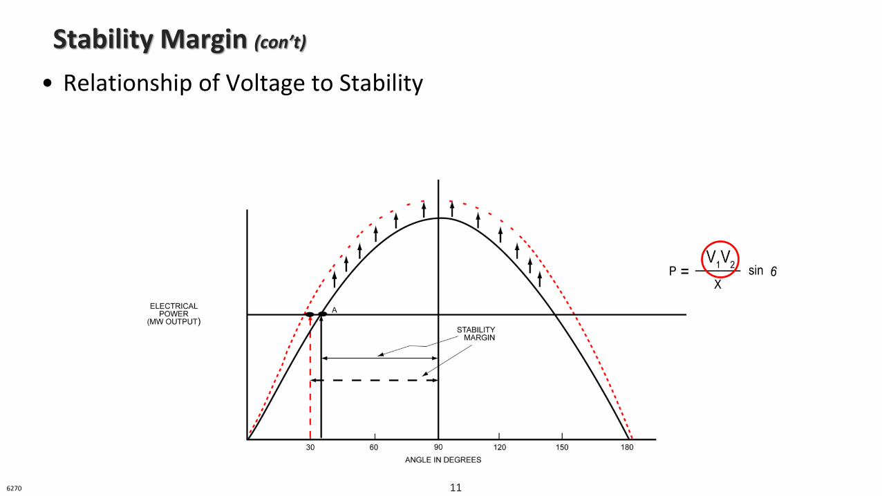
• Relationship of Voltage to Stability
Stability Margin (con’t)
6270 11
• Ability of the system to withstand small changes or disturbances from equilibrium without the loss of synchronism
‒ Stable loads
‒ Balanced generation with said loads
‒ Small, gradual changes
‒ No emergency conditions
• Consistent voltages at, or near, nominal values with AVRs in service
Steady State Stability
6271 12
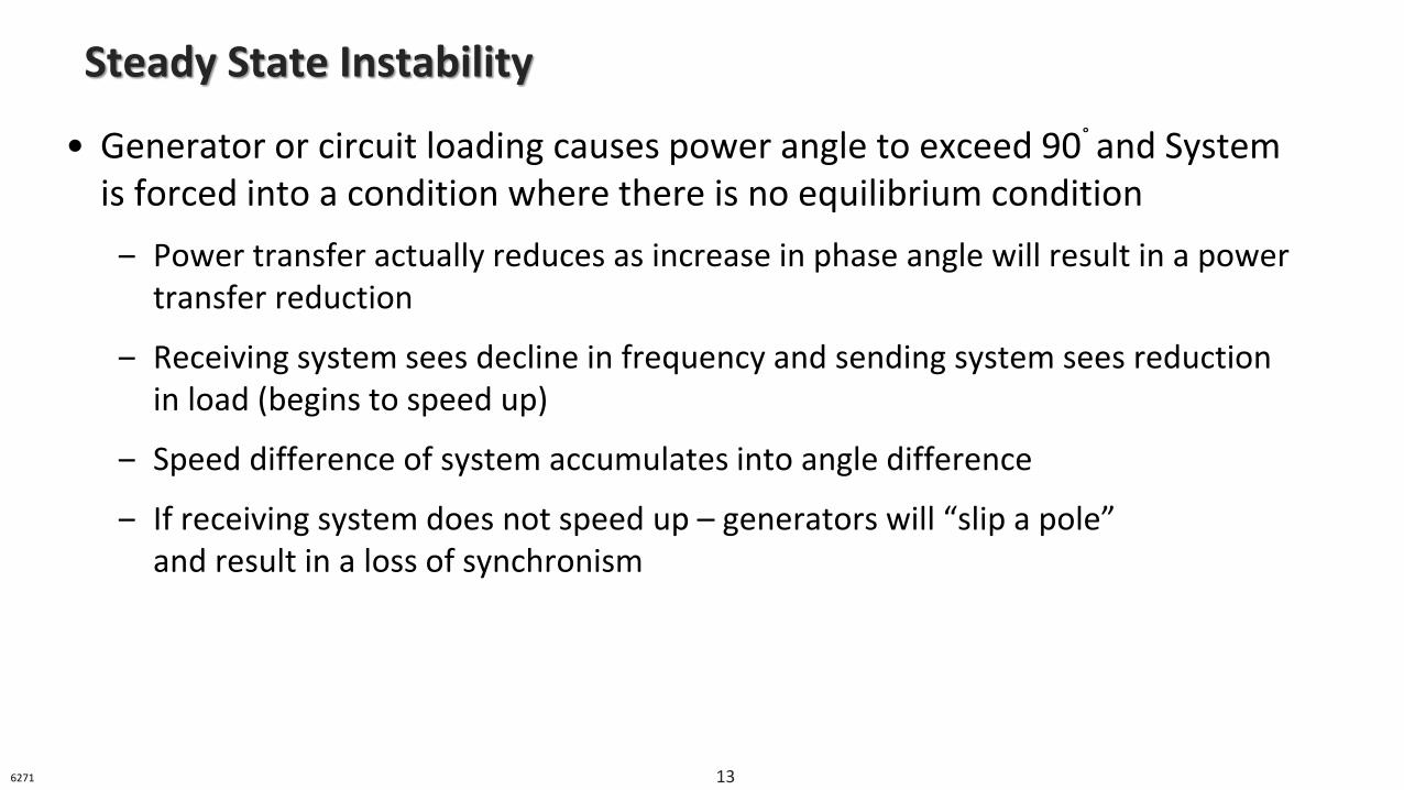
• Generator or circuit loading causes power angle to exceed 90˚ and System is forced into a condition where there is no equilibrium condition
‒ Power transfer actually reduces as increase in phase angle will result in a power transfer reduction
‒ Receiving system sees decline in frequency and sending system sees reduction in load (begins to speed up)
‒ Speed difference of system accumulates into angle difference
‒ If receiving system does not speed up – generators will “slip a pole” and result in a loss of synchronism
Steady State Instability
6271 13
• Length of the line can affect the loadability or maximum power transfer of a transmission circuit
• Not very common in general – especially on a tightly interconnected system, like PJM’s, where most transmission circuits are relatively short
Steady State Instability (con’t)
6271 14
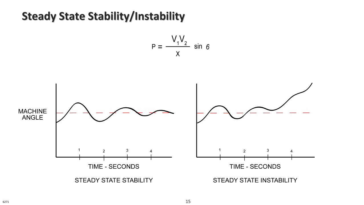
Steady State Stability/Instability
6271 15
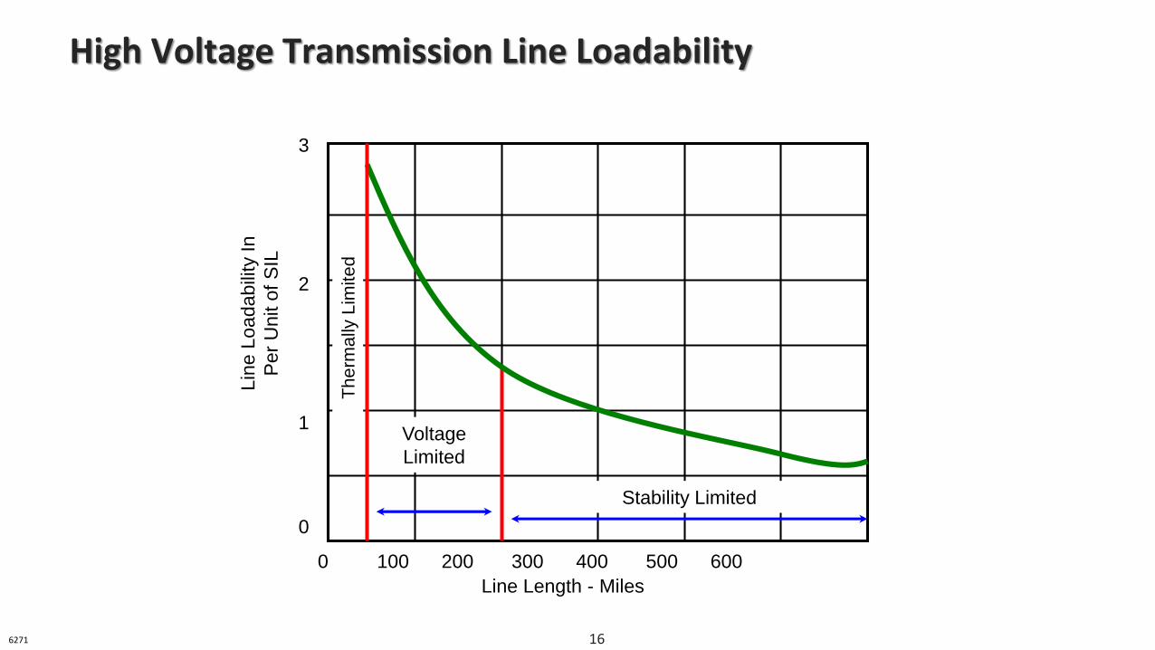
High Voltage Transmission Line Loadability
Stability Limited
Th
erm
ally
Lim
ite
d
Lin
e L
oadab
ility
In
Per
Unit o
f S
IL
3
2
1
0
0 100 200 300 400 500 600
Line Length - Miles
Voltage
Limited
6271 16
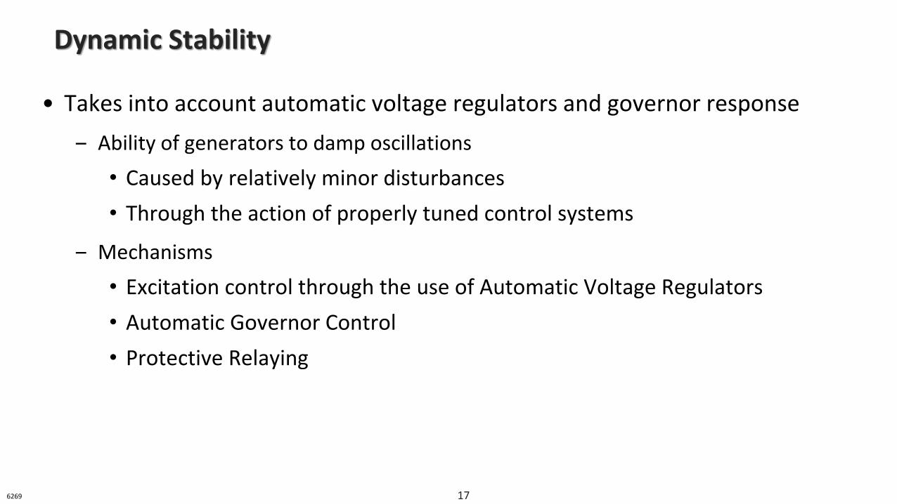
• Takes into account automatic voltage regulators and governor response
‒ Ability of generators to damp oscillations
• Caused by relatively minor disturbances
• Through the action of properly tuned control systems
‒ Mechanisms
• Excitation control through the use of Automatic Voltage Regulators
• Automatic Governor Control
• Protective Relaying
Dynamic Stability
6269 17
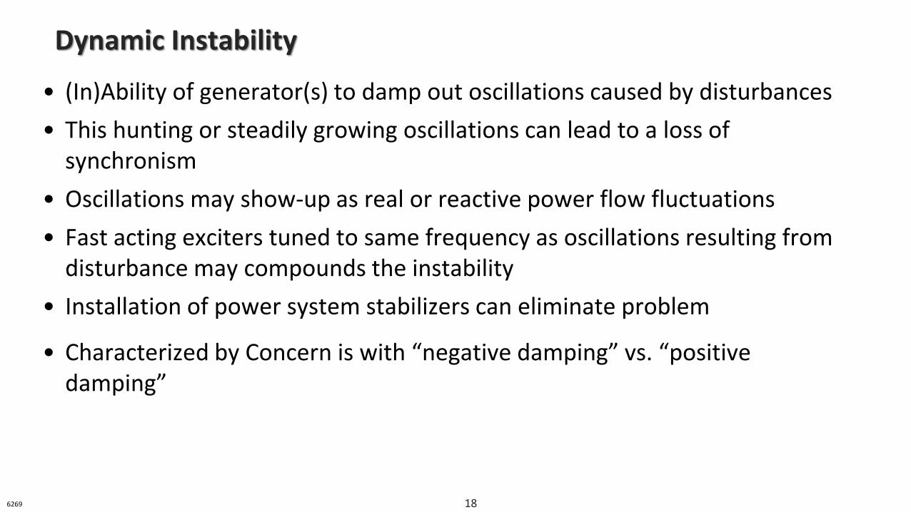
• (In)Ability of generator(s) to damp out oscillations caused by disturbances
• This hunting or steadily growing oscillations can lead to a loss of synchronism
• Oscillations may show-up as real or reactive power flow fluctuations
• Fast acting exciters tuned to same frequency as oscillations resulting from disturbance may compounds the instability
• Installation of power system stabilizers can eliminate problem
• Characterized by Concern is with “negative damping” vs. “positive damping”
Dynamic Instability
6269 18
Analogy of Dynamic Instability
6269 19
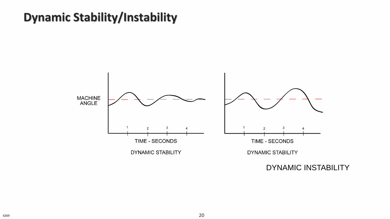
Dynamic Stability/Instability
DYNAMIC INSTABILITY
6269 20
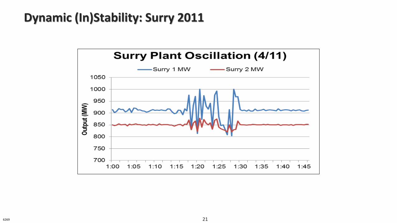
Dynamic (In)Stability: Surry 2011
6269 21
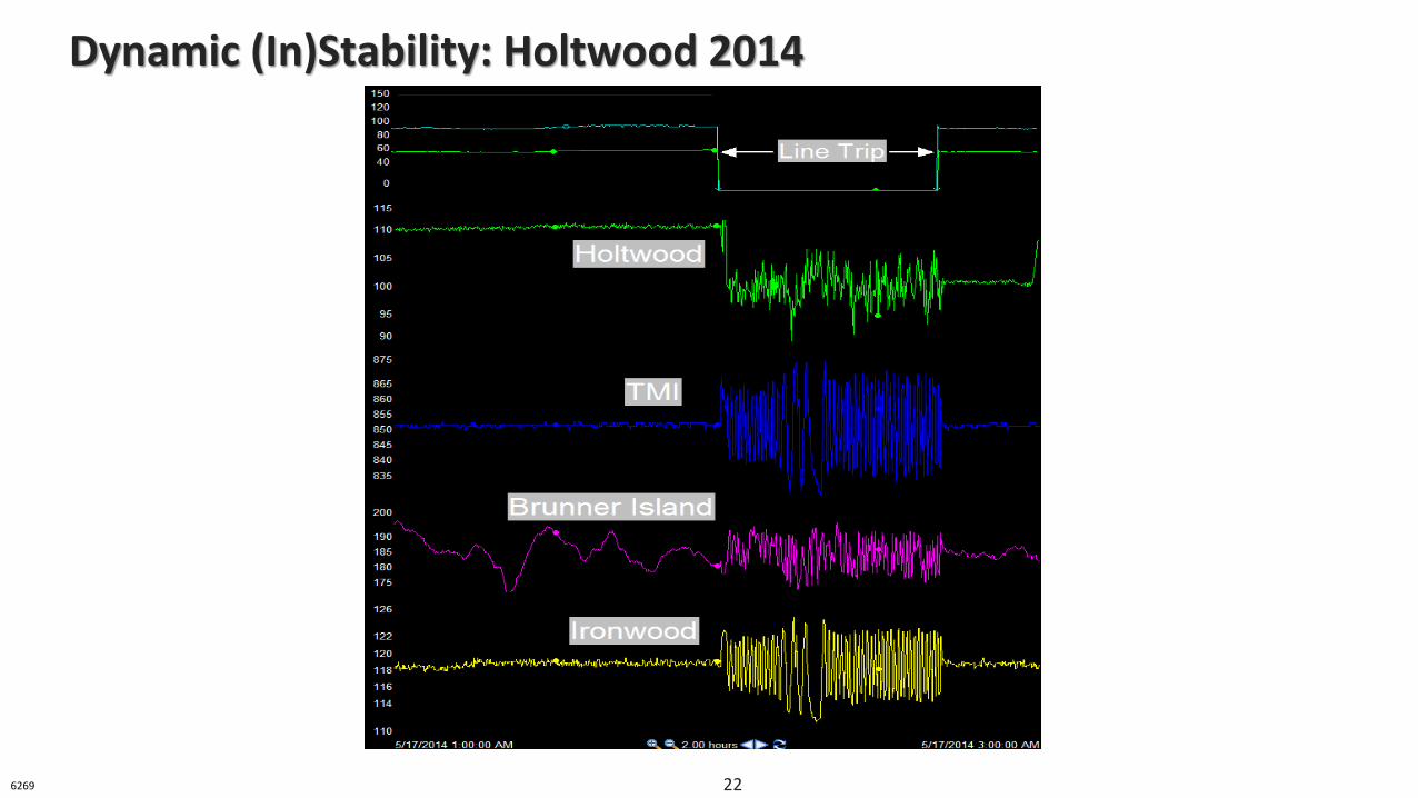
Dynamic (In)Stability: Holtwood 2014
6269 22
• The ability of a generator or group of generators to remainin synchronism immediately following a severe and sudden system disturbance (initial swing)
• Transient stability is typically viewed as “first swing” stability
• The first swing for a generator takes less than a second
• Considers the inherent mechanical and electromagnetic characteristics of the synchronous machines and the impedance of the circuits connecting them
Transient Stability
6272 23
• Inability of system generators to remain synchronized following a significant disturbance (usually a fault)
• Upon the disturbance – generator rotors accelerate then decelerate before new operating point is reached
• System is transiently stable if Accelerating Area ≤ Decelerating Area
• Multiple types of faults, examples:
‒ Three-phase (Most severe)
‒ Single phase (Less severe)
• Equivalent impedances involved in different faults varies
Transient Instability
6272 24
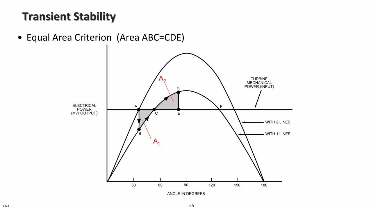
• Equal Area Criterion (Area ABC=CDE)
Transient Stability
A1
A2
6272 25
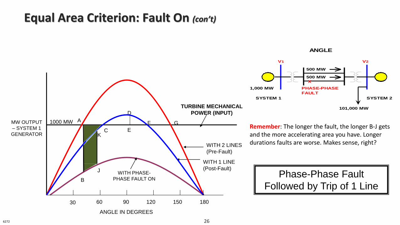
Equal Area Criterion: Fault On (con’t)
A
B
C
F
TURBINE MECHANICAL
POWER (INPUT)
WITH 2 LINES
(Pre-Fault)
WITH 1 LINE
(Post-Fault)
ANGLE IN DEGREES
MW OUTPUT
– SYSTEM 1
GENERATOR
J
K
D
E
WITH PHASE-
PHASE FAULT ON
1000 MW
30 60 90 120 150 180
Phase-Phase Fault
Followed by Trip of 1 Line
G
500 MW
500 MW
X
V1 V2
SYSTEM 1 SYSTEM 2
101,000 MW
1,000 MW PHASE-PHASE
FAULT
ANGLE
Remember: The longer the fault, the longer B-J gets and the more accelerating area you have. Longer durations faults are worse. Makes sense, right?
6272 26
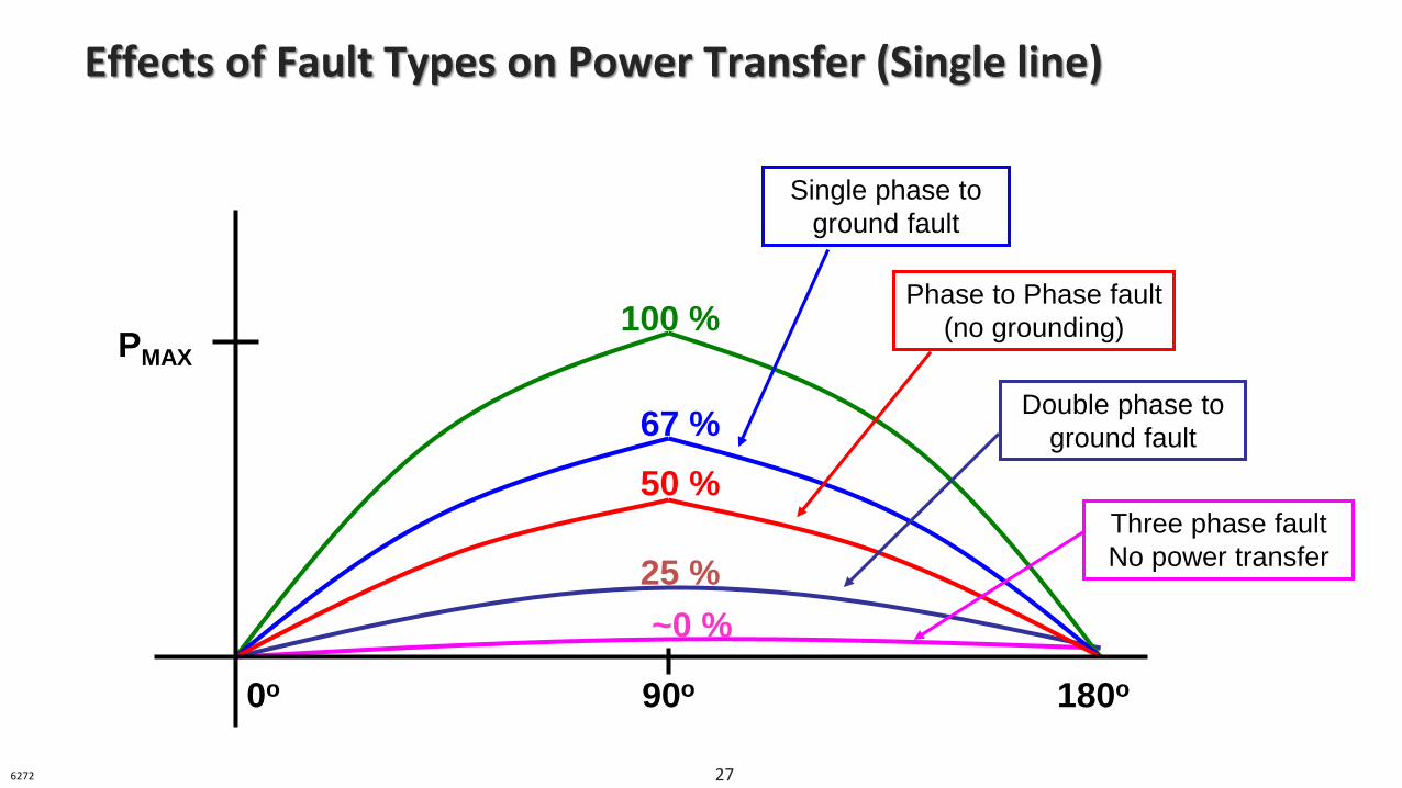
Effects of Fault Types on Power Transfer (Single line)
PMAX
0o 90o 180o
100 %
67 %
50 %
25 %
~0 %
Single phase to
ground fault
Phase to Phase fault
(no grounding)
Double phase to
ground fault
Three phase fault
No power transfer
6272 27
• Limit transfers
• Assure AVRs + PSSs in service
• Raise generator/transmission voltage
• Restore Transmission to service
• Restore Reclosing and Applicable RASs
Transient Stability: Helping your margins
6272 28
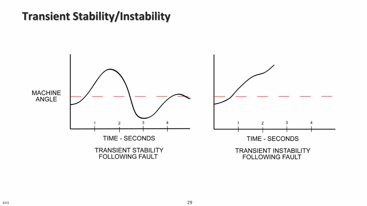
Transient Stability/Instability
6272 29
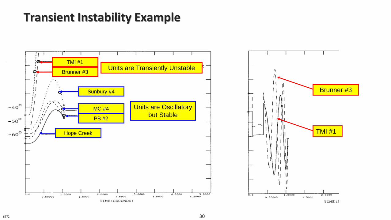
Transient Instability Example
TMI #1
Brunner #3
Brunner #3
TMI #1Units are Transiently Unstable
Hope Creek
PB #2
MC #4
Sunbury #4
Units are Oscillatory
but Stable
6272 30
• Loss (or gain) of one or more generators
• System faults/facility outages
• Low voltage operation
• High Transfers
• Automatic Voltage Regulator & Power System Stabilizer Outages
• Relay Scheme Outages
• Load changes
Typical Threats to Stability
6268 31
• Awareness
• Generator MW output
‒ Decrease MW output to increase stability
• Generator MVAr output
‒ Increase MVAr output to increase stability
• Lines in service - system strength
‒ Put more lines in service to increase stability
• Arm special relay schemes
Operator Actions Affecting Stability
6268 32
• Steady State
‒ Phase angle exceeds 90 degrees
• Dynamic
‒ Continued oscillations over long periods of time
‒ Damage to units before they are tripped
• Transient
‒ Excessive rotor angle swings
‒ Units tripped, possibly damaged, following disturbance
Consequences of Instability: Loss of synchronization
6268 33
• Transmission Operations Manual 03 – Section 5
‒ What do these guidelines contain?
• Unit restrictions for each outage that affects stability
Tripping schemes
Generator MW output restrictions
Generator MVAR output restrictions
Stability Guides
6268 34
• How are these guides developed?
‒ Guidelines are based on detailed stability studies that consider severe fault conditions (N-1) that occur under each significant outage condition (N-2) in the area of concern
‒ Guidelines are developed under very conservative assumptions of generation dispatch and load level
Stability and the PJM Generator Interconnection Process
6268 35
• When are these guides updated and developed?
‒ Guides will be updated every time a new equipment (generator or transmission) locates in vicinity of problem
‒ Anytime an area becomes concentrated with a large amount of generation relative to the transmission outlet capability of the area, a detailed stability study will be performed to see if an operating guide is needed
Stability and the PJM Generator Interconnection Process
6268 36
• Why are these guides so important?
‒ Guides usually involve several large generators that can be damaged when they are operated out-of-step with the rest of the system
‒ A generator that is operated out-of-step can cause transmission lines to trip before the generator itself trips off-line
‒ When several large generators are operated out-of-step, cascading outages and widespread load loss can result due to the fluctuations in power flows, voltage and frequency
Stability and the PJM Generator Interconnection Process
6268 37
• Stability has not yet become the most significant system limitation
• Operators need to be aware of the importance of why stability operating guides are developed and why they will be updated much more frequently than in the past
In Summary
6268 38
DSA Monitor: Dynamic Security Assessment (EMS equivalent is “Disp Mon” and “Exec Ctrl” screens)
TSA/TSAT: Transient Stability Analysis Tool(EMS equivalent is “SA”)
PSAT: Powerflow & Short-circuit Analysis Tool(EMS equivalent is Study “Powerflow”)
PCM: Preventive Control Measure(EMS equivalent is “AO” report)
Bonus: Real Time Stability Tools!
6268 39

PJM Client Management & ServicesTelephone: (610) 666-8980
Toll Free Telephone: (866) 400-8980 Website: www.pjm.com
The Member Community is PJM’s self-service portal for members to search for answers to their questions or to track and/or open cases with
Client Management & Services
Questions?
40
Resources & References
41
Bergen, A. & Vittal, V. (2000). Power System Analysis (2 ed.). Prentice Hall, Inc.
Radhakrishna, C. (1981). Transient Stability Analysis. Retrieved from https://ieeexplore.ieee.org/document/4110615/
Rustebakke, H. (1983). Electric Utility Systems and Practices (4 ed.). Wiley-Interscience.