system thermalhydraulics for dba analysis and …
TRANSCRIPT

SYSTEM THERMALHYDRAULICS
FOR DBA ANALYSIS AND SIMULATION
STATUS OF TOOLS AND METHODS
AND DIRECTION FOR FUTURE R&D
D. Bestion
Commissariat à l’Energie Atomique et aux Energies Alternatives, DEN-DM2S-STMF-LMES,
17 Rue des Martyrs, 38054, GRENOBLE, FRANCE [email protected]
ABSTRACT System thermalhydraulic investigations of Design Basis Accident require several tools and methods including the Process Identification and Ranking Table, the scaling, experiment analysis, modeling, code development, code Validation and Verification, and Uncertainty Quantification. This paper intends to give an overview of these methods and tools showing what the state of the art is, and presenting some recent advances. Recommendations are made with future direction for R&D including the need of new advanced experiments and instrumentation, and the future role of CFD and multi-scale analyses. For many people it is not clear what current system codes are, and what they can be. Then the main characteristics of these codes are recalled and propositions are made to clarify the code capabilities and limitations and to improve the knowledge of the conditions for a correct application of the codes for safety in a Best Estimate Plus Uncertainty approach. Also the on-going developments of 3-field models and Transport of Interfacial Area are summarized and associated experimental needs are identified. The growing role of 3D modelling of reactor core and Pressure Vessel requires additional experimental data for a proper validation. CFD in open medium also contributes to investigations when 3D geometrical aspects play an important role. Recent activities performed in the OECD-NEA Working Group for Analysis and Management of Accidents is summarized and recent applications of two-phase CFD to boiling flows and two-phase PTS scenarios are reported. The role of a multi-scale approach of safety issues is illustrated for the LOCA transients in LWRs. Attention is focused on the need of specific validation experiments and of consolidated uncertainty methods for both system codes and CFD codes. KEYWORDS System thermalhydraulics, BEPU, Scaling, Multi-scale simulation
3420NURETH-16, Chicago, IL, August 30-September 4, 2015 3420NURETH-16, Chicago, IL, August 30-September 4, 2015

1. INTRODUCTION
System thermalhydraulic investigations of Design Basis Accident (DBA) require several tools and methods including the Process Identification and Ranking Table (PIRT), the scaling, experiment analysis, modeling, code development and Validation and Verification (V&V), and Uncertainty Quantification (UQ). This paper gives an overview of these methods and tools, presents the state of the art and some recent advances. Each step is considered and the role of the system codes is emphasized Attention is drawn the scale-up capability of system codes. Then the status of the uncertainty methods is presented showing what should be further investigated on the determination and validation of the uncertainties of closure laws. For many people it is not clear what current system codes are, what they should be, and what they can be. Then the main characteristics of these codes are recalled and propositions are made to clarify the code capabilities and limitations and to improve the knowledge of the conditions for a correct application of the codes for safety in a Best Estimate Plus Uncertainty (BEPU) approach. Also the on-going developments of 3-field models and Transport of Interfacial Area (TIA) are summarized and associated experimental needs are identified. The growing role of 3D modelling of reactor core and Pressure Vessel (PV) requires additional experimental data for a proper validation. CFD in open medium also contributes to investigations when 3D geometrical aspects play an important role. Recent activities performed in the OECD-NEA Working Group for Analysis and Management of Accidents is summarized and recent applications of two-phase CFD to boiling flows and two-phase PTS scenarios are reported. The role of a multi-scale approach of safety issues is illustrated for the LOCA transients in LWRs. Attention is focused on the need of specific validation experiments and of consolidated uncertainty methods for both system codes and CFD codes. The two-phase CFD significantly progressed for a few applications and multiscale analyses are in progress. The status is summarized and the role in the solution of reactor issues is illustrated by some examples. Recommendations are made with future direction for R&D including the need of new advanced experiments and instrumentation, and the future role of CFD and multi-scale analyses
2. THE METHODS AND TOOLS FOR DBA ANALYSIS
The reactor safety demonstration requires the analysis of complex problems related to accident scenarios. The equations of fluid motion and heat transfer are known but cannot be solved in a complex system due to the turbulence and the two-phase flows which have a wide spectrum of interacting scales from microscopic to macroscopic. No analytical solution exist and numerical solution of exact equations is still beyond the computer capabilities. Experiments cannot reproduce at a reasonable cost the physical situation without any simplification or distortion and the numerical tools cannot simulate the problem by solving the exact equations. Only reduced scale experiments are feasible to investigate the phenomena and only approximate system of equations may be solved to predict time and/or space averaged parameters with errors due to imperfections of the closure laws and to numerical errors. Therefore complex methodologies are necessary to solve a problem including a PIRT analysis, a scaling analysis, the selection of scaled Integral Effect Tests (IET) or Combined effect tests (CET) and Separate Effect Tests, the selection of a numerical simulation tool, the Verification and Validation of the tool, the code application to the safety issue of interest and the use of an uncertainty method to determine the uncertainty of code prediction. This global approach is illustrated in Figure 1.
3421NURETH-16, Chicago, IL, August 30-September 4, 2015 3421NURETH-16, Chicago, IL, August 30-September 4, 2015

2.1 The PIRT
Phenomena identification is the process of analyzing and subdividing a complex system thermal-hydraulic scenario into several dominant processes or phenomena. Usually, there is a parameter of interest in the thermal-hydraulic scenario which may be a safety criterion (e.g. a peak clad temperature, a reactivity insertion, a thermal or mechanical load,…). Ranking means here the process of establishing a hierarchy between identified processes with regards to its influence on the parameter of interest. PIRT is a formal method described by Wilson & Boyack [1]. The main steps of the physical analysis based on PIRT are:
� Establish the purpose of the analysis and specify the reactor transient (or situation) of interest � Define the dominant parameters or FoM (figures of Merit) � Identify and rank key phenomena with respect to their influence on the FoM � Identify dimensionless numbers controlling the dominant phenomena
PIRT can be based on expert assessment, on analysis of some experiments, and on sensitivity studies using simulation tools. As it is an iterative process one can start with expert assessment and then iterate after some experiment analysis and/or with some sensitivity studies performed with thermalhydraulic codes to refine the PIRT conclusions.
2.2 Scaling
When dominant phenomena are identified and ranked, experiments are designed to simulate at reduced scale and power the reactor transient in Integral Effect Test (IET) facilities and in Separate Effect Test facilities. Scaling of an experiment is the process of selecting the non-dimensional numbers to be respected for having a good similarity with the reactor behaviour at least for the dominant processes. For application in nuclear reactor safety, a comprehensive methodology named H2TS (“Hierarchical Two Tiered Scaling”) was developed by a Technical Program Group of the U.S. NRC under the chairman N. Zuber [2] (1991). This work provided a theoretical framework and systematic procedures for carrying out scaling analyses (Zuber at al. [3]). The name is based on using a progressive and hierarchized scaling
3422NURETH-16, Chicago, IL, August 30-September 4, 2015 3422NURETH-16, Chicago, IL, August 30-September 4, 2015

organized in two basic steps. The first one from top to down, T-D, and the second step from bottom to up (B-U) The first step T-D is organized at the system or plant level and is used to deduce non-dimensional groups that are obtained from mass (M), energy (E) and momentum (MM) conservation equations, obtained from the systems that have been considered as important in a PIRT. These non-dimensional groups are used to establish the scaling hierarchy i.e. what phenomena have priority in order to be scaled, and to identify what phenomena must be included in the bottom-up analysis. The second part of the H2TS methodology is the B-U analysis. This is a detailed analysis at the component level that is performed in order to assure that all relevant phenomena are properly represented in the balance equations that govern the evolution of the main magnitudes in the different control volumes. The PIRT associated to H2TS may lead to the scaling of experimental data of both IET type and of SET type. When solving a reactor thermalhydraulic issue the answer to the issue may be:
1. Purely experimental: the experiments can tell what would occur in the reactor with sufficient accuracy and reliability (dotted arrow in Figure 1)
2. Both experiments and simulation tools are used to solve the issue. The first case is not frequent and simulation tool are most often used to extrapolate from experiments to reactor situation - this is the upscaling process- and the degree of confidence on this extrapolation is part of the scaling issue. When dominant phenomena are affecting the whole behavior of the system, a system code is necessary. This is the case of many transients like loss of coolant accidents (LOCAs), steam line break (SLB), loss of feedwater (LOFW), loss of electrical power, loss of residual heat removal (LORHR) and others. When local complex 3D phenomena are playing a dominant role, CFD codes may be required or even a coupling of system and CFD codes. The scaling analysis is based on the PIRT but it can also help the PIRT by helping in the ranking of phenomena. Zuber et al. [4] proposed the Fractional Scaling Analysis (FSA) which is a quantitative methodology to scale evolution of processes with interacting modules and processes, and to integrate information and data for reactor transient analysis. FSA identifies dominant processes rank them quantitatively and provides an objective basis for PIRT as well as for uncertainty analysis. It was applied to LOCA by Wulff et al. [5] and Catton et al. [6] and could predict Peak Clad Temperature (PCT) with an uncertainty on the basis of existing data and without any code. However there is no reason to do the work without codes which can help at several steps of the process of solving a complex reactor issue and we try here below to list the requirements for a proper use of system codes in a Best-Estimate Plus Uncertainty (BEPU) approach. The use of time scales in scaling methods appears to be a convenient way of identifying the relative importance of processes. All non-dimensional numbers may be seen as a ratio of the time scales associated to two physical processes. One may then consider two cases:
� Several processes are coupled in a sequential way to contribute to a phenomenon: the larger time constant will control the phenomenon. For example a heat transfer from a fuel rod to the coolant may include conduction in the pellet, conduction and radiation in the gap, conduction in the clad, and convection to liquid. If the time constant associated to convection is much larger than the other time constants having it is not necessary to represent very precisely the fuel rod transfers to predict the heat transfer to liquid. This remains true as long as the time evolution of the convection to fluid remains also large. When clad-to-fluid transfer changes very rapidly (CHF occurrence in a blowdown phase of a LBLOCA), the larger time scale may be associated to the conduction in the fuel pellet and an experiment needs a rod design which respects the pellet conductivity.
� Several local processes contribute in parallel to a more macroscopic quantity evolution in a control volume: one can evaluate the ratio of the control volume fill time scale and process intensity time scale. This establishes a hierarchy of processes and higher levels in the hierarchy should be preserved.
3423NURETH-16, Chicago, IL, August 30-September 4, 2015 3423NURETH-16, Chicago, IL, August 30-September 4, 2015

Such scaling methods may be used not only for scaling IETs and SETs but also to define a hierarchy of phenomena which should be modelled in the codes. In both applications compromises are very often necessary. In scaling an IET to investigate a reactor transient it is easy to respect some highly ranked processes and to neglect some low priority processes but usually there are a few medium rank processes which are distorted. In a code development there may be difficulties to model all phenomena of interest for all possible transients. The level of physical description is also a compromise with the complexity and with the available experimental information required for validation. There may be distorted phenomena predicted by codes due to simplifying assumptions which are not justified in some application cases. Examples of distortions in IET and in system codes are given here below.
2.2.1 Distortion in a IET
A classical scaling of IET uses the Kv-scaling or power-to-volume scaling where the same reduction factor is applied to power, volume and flowrate. If vertical scale is preserved, channels are thin and tall. This is
not a problem in core and SGs since one may just reduce the number of rods (resp. tubes) and respect the hydraulic diameter, this preserves all non-dimensional numbers that are important for friction losses, heat transfers, flow regime, and interfacial transfers.
However in an annular donwcomer this induces a strong distortion which may affect the flow regime and the global behavior. Horizontal legs of a PWR should respect a Froude similarity in order to respect the stratification criterion. This induces some distortions of Reynolds and Kutateladze numbers:
Figure 2: SETs used in the CATHARE code Validation to solve the BETHSY IET distortion problem for CCFL and flooding limit
One may expect that droplet entrainment occurrence will not be respected which plays a significant role in a LBLOCA Reflooding. Also the aspect ratio or shape of the bend and inlet header of steam generator (SG)
3424NURETH-16, Chicago, IL, August 30-September 4, 2015 3424NURETH-16, Chicago, IL, August 30-September 4, 2015

is not respected and one may expect distortions in the CCFL in such components and this may induce a wrong liquid mass repartition in some small break (SB) or intermediate break(IB) LOCAS. This CCFL distortion problem can be solved by using system codes provided that they are able to predict with the same reliability the CCFL in reactor geometry and in IET geometry. Figure 2 shows a set of experiments which were used for CATHARE code validation. It includes CCFL tests in the same geometry as the BETHSY IET but also reduced scale and scale 1 data in reactor geometry. This is a typical case where the system code can solve the distortion in an IET by validation on SETs. For the droplet behavior in a hot leg during a Reflooding specific SET were designed to investigate droplet entrainment and deposition in order to develop adequate models able to predict different behavior in distorted IETs and in reactor. However one may encounter another source of distortion due to limitations of the physical model of system codes. This is explained here below.
2.2.3 Distortion of physical processes in a system code
Distortion may be encountered in thermalhydraulic codes due to some simplifying assumptions which are not satisfied in all conditions of interest. The two-fluid model is used in most system codes and it has extended capabilities to model correctly. Let us consider the models which control the slip between phases. In the case of bubbly-slug churn flow regimes, the steam is in small or large bubbles and the relative motion of these bubbles within the liquid is the result of drag force, inertial forces, and buoyancy forces as can be seen in the following equation derived from liquid and gas momentum equations after elimination of the pressure gradient:
Scaling analysis shows that the drag and buoyancy forces are dominant compared to other forces such as inertia. This would allow to eliminate all the other forces and to keep an algebraic relation corresponding to an equilibrium slip obtained with drag equal buoyancy. This is the approach of the drift flux model. This shows that the two-fluid model with two momentum equations is not necessary in this flow regime and a more simple model with one mixture momentum equation + a drift flux model is sufficient. However one may also consider that the bubbles are created at the wall with a very small sizes and detach from the wall are transported by the liquid, collide with other bubbles and coalesce or may be broken by eddies. They may also change in size by vaporization or condensation. All these processes affect the bubble size and consequently the equilibrium slip. So processes affecting the bubble size and phenomena affecting the slip between phases are processes coupled in a sequential way and one should determine their time scale to determine which phenomena can be neglected. It is now very clear that the time scale associated to coalescence and break up of bubbles may be larger than the time scale for a bubble of given size to reach an equilibrium slip. Then additional equation to predict the bubble size would be required, such as a transport equation for interfacial area. This approach has been developed for 15 years but no industrial code version use it since there is still a lack of validation data. The case of a steam + droplet flow as encountered in a core during reflooding would lead to different conclusions. Droplet are created at the quench front and are entrained to the top of the core by steam flow. Using the same equation as above, scaling analysis would show that inertial forces play a dominant role as well as gravity and drag forces. As shown in figure 3, the droplet velocity increases towards an equilibrium slip but many droplets do not reach this equilibrium within the core. Since the velocity difference plays a dominant role in the steam-to-droplet heat transfer, it is much better to take inertia of droplets into account and two momentum equations are doing a much better job than algebraic slip in such case. This was one of the reasons why all current system codes have at least the two fluid model.
3425NURETH-16, Chicago, IL, August 30-September 4, 2015 3425NURETH-16, Chicago, IL, August 30-September 4, 2015
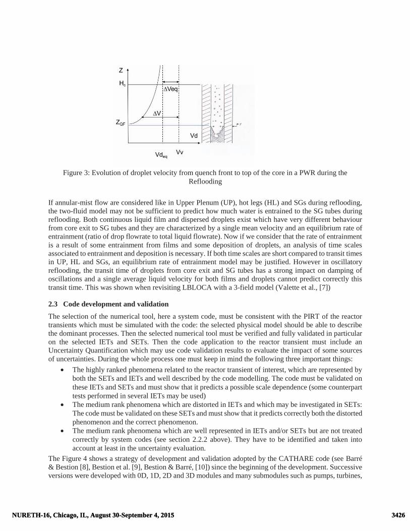
Figure 3: Evolution of droplet velocity from quench front to top of the core in a PWR during the Reflooding
If annular-mist flow are considered like in Upper Plenum (UP), hot legs (HL) and SGs during reflooding, the two-fluid model may not be sufficient to predict how much water is entrained to the SG tubes during reflooding. Both continuous liquid film and dispersed droplets exist which have very different behaviour from core exit to SG tubes and they are characterized by a single mean velocity and an equilibrium rate of entrainment (ratio of drop flowrate to total liquid flowrate). Now if we consider that the rate of entrainment is a result of some entrainment from films and some deposition of droplets, an analysis of time scales associated to entrainment and deposition is necessary. If both time scales are short compared to transit times in UP, HL and SGs, an equilibrium rate of entrainment model may be justified. However in oscillatory reflooding, the transit time of droplets from core exit and SG tubes has a strong impact on damping of oscillations and a single average liquid velocity for both films and droplets cannot predict correctly this transit time. This was shown when revisiting LBLOCA with a 3-field model (Valette et al., [7])
2.3 Code development and validation
The selection of the numerical tool, here a system code, must be consistent with the PIRT of the reactor transients which must be simulated with the code: the selected physical model should be able to describe the dominant processes. Then the selected numerical tool must be verified and fully validated in particular on the selected IETs and SETs. Then the code application to the reactor transient must include an Uncertainty Quantification which may use code validation results to evaluate the impact of some sources of uncertainties. During the whole process one must keep in mind the following three important things:
� The highly ranked phenomena related to the reactor transient of interest, which are represented by both the SETs and IETs and well described by the code modelling. The code must be validated on these IETs and SETs and must show that it predicts a possible scale dependence (some counterpart tests performed in several IETs may be used)
� The medium rank phenomena which are distorted in IETs and which may be investigated in SETs: The code must be validated on these SETs and must show that it predicts correctly both the distorted phenomenon and the correct phenomenon.
� The medium rank phenomena which are well represented in IETs and/or SETs but are not treated correctly by system codes (see section 2.2.2 above). They have to be identified and taken into account at least in the uncertainty evaluation.
The Figure 4 shows a strategy of development and validation adopted by the CATHARE code (see Barré & Bestion [8], Bestion et al. [9], Bestion & Barré, [10]) since the beginning of the development. Successive versions were developed with 0D, 1D, 2D and 3D modules and many submodules such as pumps, turbines,
3426NURETH-16, Chicago, IL, August 30-September 4, 2015 3426NURETH-16, Chicago, IL, August 30-September 4, 2015

heat structures, fuel rods, heat exchangers, breaks, valves?... Successive consistent sets of closure laws (called “Revisions 1, 2,,, n) are also developed and validated. Closure laws (see Bestion, [11]) are taken either from known previous work or from analysis of specific Sets. When a whole set of closure laws is available, the Revision is frozen and the Version + Revision follows a complete validation process with SETs and IETs. Validation on SETs allows to check the quality of each closure law in a separate effect way. When the dominant phenomena at the process level and associated relevant non-dimensional numbers are well identified, some parameters may be fitted on the experiment and the predictions may be rather precise. When some phenomena are not modelled or distorted by the code it may result in some significant differences between the predictions and measurements. A limited accuracy is obtained which will be taken into account in the Uncertainty quantification. When the disagreement is too large, a return to the analysis of data may be necessary to correct the formulation of the closure law. Validation on IETs checks the consistency of all closure laws together. When some significant errors are found in predictions they are analyzed and possible sources of errors are identified. No tuning of any closure law is allowed to improve an IET simulation. This would probably induce some compensating errors which would improve the prediction in this test but without possible extrapolation to other situations. Usually new SETs are built and analyzed to confirm the origin of the error and to improve the modelling of some phenomena which were not well described in the code. Validation on SETs is also used to determine the uncertainty on each closure law. This uncertainty is determined from sensitivity of code responses upon closure laws and from error in code predictions which are treated by a statistical tool (CIRCE) to determine the uncertainty on the closure laws (de Crecy [12]), de Crecy & Bazin, [13]). These uncertainties should be validated themselves by proving that they bound measured parameter values of all SETs.
Figure 4: Strategy for development and validation of a frozen Version + revision of physical models of
the CATHARE code
3427NURETH-16, Chicago, IL, August 30-September 4, 2015 3427NURETH-16, Chicago, IL, August 30-September 4, 2015

Codes must be validated at reactor and component and process levels to demonstrate its capability to simulate all important processes for each transient. Then codes should respect some requirements to do the upscaling up to the reactor scale. Figure 2 shows a strategy for development and validation of a frozen Version + revision of physical models of the CATHARE code. SET data are analysed to develop or improve closure laws of the code. When a set of consistent closure laws was developed this is called a new “Revision” of the physical model. The Version with this Revision is frozen and follows an extensive V&V process. Verification is a preliminary step which controls the quality of the numerical scheme and the correct coding of all equations and algorithms. Verification is associated to the Version (set of modules) whereas Validation is associated to a Revision (set of models).
3. THE SYSTEM CODES
3.1 The current system codes
The development of the present generation of system codes was initiated in the years 1970 to 1980. The main objective of developing these codes was to replace Evaluation Models which used many conservative assumptions by the best-estimate approach for more realistic predictions of PWR or BWR accidental transients. Such codes may have a wide range of applications from research to safety and design purposes. Examples of applications are:
� Safety analysis � Quantification of the conservative analyses margin � Investigation of Plant Operating Procedures and Accident Management � Definition and verification of Emergency Operating Procedures � Investigations for new types of fuel management � Preparation and interpretation of experimental programs with scaling analyses � Licensing when used in a BEPU approach � Design of new reactors and systems including passive features for the 3rd and 4th generations of
NPP � System code application has been often extended to the field of severe accidents. For this purpose
they are coupled with other codes, which model core degradation and fission product release. � Implementation in Full Scope Plant Simulator: simplified versions were first used to obtain real
time simulations and later, thanks to the increasing computer performance, the standard versions were used
Building such system codes was very challenging with respect to a number of difficulties: � Geometrical complexity of the systems: the geometry of the flows within reactor circuits is
extremely complex and has to be drastically simplified in order to allow a coarse nodalization while keeping reliable predictions of macroscopic parameters
� Variety of two-phase flows: the very wide scope of transients to simulate with system codes covers all types of two-phase flow regimes and all regimes of heat transfers with heating or cooling walls
� Wide range of physical parameters: 0.1<P<20MPa, T< 1200°C, Velocity up to sonic � CPU time must remain compatible with an industrial use: all type of accidental transients including
Large Break LOCAs must be simulated in a reasonable time (e.g. 12 hours) allowing many sensitivity tests to be performed in addition to a base case calculation
� Selecting phenomena which deserve a specific modelling effort: since the variety of flow regimes, heat transfer regimes, and geometric configuration is extremely wide, most important phenomena
3428NURETH-16, Chicago, IL, August 30-September 4, 2015 3428NURETH-16, Chicago, IL, August 30-September 4, 2015

for safety issues have to be identified and a specific effort has to be paid for an appropriate modelling of these dominant and sensitive phenomena.
� Selecting the right level of complexity of the models: the level of complexity of the model must remain compatible with the available scientific knowledge, with available experimental data for validation, and with the required reliability of predictions for safety
Nearly all current two-phase flow models used in present “best estimate” thermal hydraulic system codes are based on the “two-fluid model”. Phases are treated as interpenetrating continua and “macroscopic” separate balance equations for each phase are obtained by a space and/or time or ensemble averaging of the local instantaneous basic flow equations, with source terms representing the interfacial transfers for mass, momentum and energy. Due to the averaging, information on local flow processes, in particular at the interface separating the two phases or at the region near the walls, is lost and has to be compensated by additional modeling.
3.2 Developing closure relations
Physical models are required to close the system of equations. Closure relationships concern mass, momentum, and energy exchanges between phases and between each phase and the wall. In a first step, code developers look at the scientific literature to find such models. When they exist, they are often developed based on theoretical work and from rather academic experimental data such as air-water flow in a circular pipe with a large length to diameter ratio. They must be later confronted to more industrial flow conditions, with steam-water data in larger ducts of various shapes. Specific separate effect tests were performed and analyzed to investigate two-phase flows in conditions more representative of the reactor transients to be simulated. Based on these data new correlations were developed when existing models were not satisfactory. The degree of empiricism depends on the comprehension of the physical mechanisms involved. In the domain where experimental and theoretical knowledge was still missing, extrapolations were adopted by making simple assumptions. Thermal and mechanical transfers are interconnected in steam-water two-phase flows. However it was often assumed in a first approximation that mechanical interactions do not strongly depend on thermal exchanges. A step-by-step method was then used. Mechanical terms were first derived from experiments where thermal non equilibrium is negligible. Interfacial heat transfer terms were then derived. Finally wall to fluid heat fluxes are correlated. One may distinguish four different approaches used to establish the closure relations:
� The fully empirical approach: representative experiments are carried out in the required range of parameters and a transfer term of the system of equations is measured together with the main variables. A correlation is then established between the transfer term and the main variables of the flow by using some fitting technique or interpolation technique. CATHARE, TRACE and RELAP use CHF look up tables for the Critical Heat Flux prediction. This method may be the most accurate but it requires a lot of experimental data and it does not allow extrapolations out of the domain covered by data.
� Empirical approach with dimensional analysis: correlations are here expressed with dimensionless numbers. Since many dimensionless numbers exist in two-phase flows, a preliminary analysis may allow to identifying the controlling physical processes and only the dimensionless parameters which re supposed to play a role are used in the correlation. This method was used to establish “Full range drift flux correlations” by EPRI (Chexal, & Lellouche, [14]).
� The phenomenological or mechanistic approach: A governing physical mechanism is assumed and an expression of the transfer term is derived theoretically. Expressions of the added mass force, or of the interfacial pressure difference term in stratified flow in the CATHARE code (see Bestion and Serre, [15]) are examples of this method. The validity is verified a posteriori by comparison with experimental data. The quality depends on the appropriateness of the basic assumptions made on the governing processes.
3429NURETH-16, Chicago, IL, August 30-September 4, 2015 3429NURETH-16, Chicago, IL, August 30-September 4, 2015

� The semi-empirical approach: Compared to the previous method, weaker assumptions are made, which allow to deriving expressions theoretically with some free parameters to tune with experimental data. The interfacial friction or interfacial heat transfer expressions are often of this type. This is the most common approach and it was used for interfacial friction in the CATHARE code (see Bestion & Matteo, [16]).
First versions of the system codes used mainly the mechanistic approach based on academic work but, after an extensive validation, the degree of empiricism of closure relations was progressively adapted to the lack of comprehension and to the complexity of the physical mechanisms involved in such a large variety of two-phase flows. In order to allow mechanistic modelling, flow regime maps are used to predict the interfacial structure of the flow. However existing flow regime maps have limitations:
� Range of validity: no observations are available in high pressure steam water flows to validate the flow maps in such reactor conditions. Also data in large diameter pipes are very limited.
� Flow geometry: very limited observation of flows in complex geometry (rod bundle) is available although geometrical effects are likely to be significant. Also effects of some singularities are not taken into account.
� Steady and established flows are necessary to establish such maps, and they are extrapolated in transient or non-established conditions. History effects and relaxation time constants associated with regime transitions are not taken into account.
Looking at the closure laws used in RELAP5/MOD3 [17], TRACE V5.0 [18] and CATHARE (Bestion, [11]) one can draw some conclusions:
� Codes rarely selected the same correlation. First versions of the codes used mechanistic models which were often modified through empirical corrections after comparison with experimental data of the validation.
� Even when codes do not use the same basic correlation, they often converged to the same degree of empiricism in the selected final correlation. The level of empiricism corresponds to the understanding and the degree of ignorance on basic processes
� A high accuracy is not required for all models and more attention was paid to the most sensitive models in accidental transients and an effort was made to improve them using corrections based on experimental validation. The sensitivity to the models being not uniform, it results that the accuracy and reliability of the models is not uniform.
After 30 years of validation and improvements, system codes are able to predict the main dominant phenomena of most accidental transients of PWR & BWR with a reasonable accuracy and allow reliable conclusions on safety issues (see Bestion, [19]).
Was the two-fluid model the right choice?
The present generation of system codes is based on the two-fluid model. This choice was made after having identified unacceptable drawbacks of previous models. In the domain of simulation of system codes for reactor accidental transients, all kinds of thermal and mechanical non equilibrium may exist. Sub-cooled liquid with direct contact condensation after ECCS injection have to be modelled. Superheated vapour has to be modelled mainly when Post-CHF heat transfer occurs in the core. Meta-stable superheated liquid and sub-cooled vapour exist in flashing flows with a small relaxation time constant (of the order of 10-3 second). Only models with two mass balance equations plus two energy balance equations can model all these situations. Mechanical non equilibrium is also encountered in most situations with possible weak coupling between phases. Using only one momentum equation with a drift flux models is sufficient for many situations, particularly when the coupling between phases is rather strong. Two momentum equations are necessary in other cases particularly when inertial forces play a role in the slip ratio. Droplets created in a Core during a
3430NURETH-16, Chicago, IL, August 30-September 4, 2015 3430NURETH-16, Chicago, IL, August 30-September 4, 2015

reflooding are entrained by steam but do not reach the equilibrium slip velocity before leaving the core due to high inertia. Better capabilities are also found for stratified flows by writing two momentum equations, which allow to represent wave propagation phenomena. The choice of the two-fluid model promoted a very extensive experimental program required for validating all closure relations. Due to this effort, the choice of the two-fluid model was a success. Multi-field models are expected to have better capabilities for annular-dispersed flows or stratified-dispersed flow.
3.3 The predictive capabilities and up-scaling capabilities of system codes
Main limitations of the present system codes
As mentioned above, the accuracy of the various models is not uniform since more attention was paid to the most sensitive models in accidental transients. A rather high degree of empiricism was necessary for some models reflecting a lack of understanding of all governing physical processes. These two reasons make system code application to new transient situations or new geometry somewhat hazardous. New experimental programs with industrial configuration are still required for any new reactor design. The intrinsic limitations of the two-fluid 6-equation model were reached in this generation of system code. Further progress would require additional equations, such as transport equations for interfacial area or for turbulent scales, or a multi-field modelling. These were the conclusions of several OECD-CSNI specialist meetings [20], [21], [22]. Another important limitation of present system codes is related to the coarse nodalization of reactor circuit required by CPU cost. The geometrical complexity is then very simplified and specific effects cannot be predicted. The CCFL is an example of sensitive phenomenon which is very geometry dependant. System codes are not predictive. One must perform a dedicated SET to measure the flooding curve in the real geometry and implement the flooding model in the system code as an option after a translation into a specific local interfacial friction model (see Freitas & Bestion, [23]).
Code up-scaling capability
Codes which are validated on some scaled SETs and IETs may have the capability to predict the phenomena of interest at reactor scale provided that some conditions are satisfied. This is called the up-scaling or scaling-up capabilities. Among the main conditions to satisfy one may find:
� The code has been validated on the transients of interest performed in scaled IETs which represent the dominant phenomena of the transient as identified in a PIRT, and predicts well qualitatively and quantitatively the main phenomena
� The code has been validated on the transients of interest performed in several scaled IETs at different scales and the code predicts the scale effect or the absence of scale effect
� The code has proved that closure laws have a good upscaling capability by validation of all important phenomena at local or component scale against several SETs at different scales
� The code has proved that closure laws validation domain cover the entire prototypical thermal hydraulic range of interest
� Since scaled IETs have necessarily some scale distortions, the code should be able to predict correctly the distorted phenomena. This may require a validation of the distorted (in IETs) phenomena in non-distorted SETs
� The uncertainty of code prediction should take into account the uncertainty due to IC and BC, material properties, physical models, numerical errors, and should also estimate the uncertainty due to non-modelled phenomena or code distortions due to limitations of the physical model.
3431NURETH-16, Chicago, IL, August 30-September 4, 2015 3431NURETH-16, Chicago, IL, August 30-September 4, 2015

3.4 The 3-field modelling in system codes
The annular-mist flow is clearly better described by a 3 field model with separate balance equations for droplets and continuous liquid. This approach has been developed for a long time in the context of dry-out investigations for Boiling Water Reactors. The interest for PWR was shown when revisiting LBLOCA with a 3-field model (Valette et al. [7]). This requires additional experimental data for validation with information on droplet entrainment and deposition. Several codes are now being developed with a 3-field model as a standard model or as an option such as SPACE, CATHARE-3 or TRACE. These models will come to maturity sooner than TIA since they extend the 2-fluid model only for one flow regime and the additional validation is limited.
3.5 The dynamic modelling of interfacial area
A dynamic modelling of interfacial area (IA) in system codes may be a way to go beyond limitations of current codes by taking into account times scales associated with coalescence, break up phenomena and flow regime transitions. The experience gained so far in developing a dynamic modelling of IA was summarized by Bestion and Serre [24]:
� The IA data and TIA models available today cannot yet be used to improve system codes and cover only a very small fraction of the flow situations of interest.
� The analysis of some flow regimes with new measurement giving access to IA and bubble size distribution has confirmed that almost all flow are non-established flows. In such condition an algebraic IA modeling has limitations, a TIA equation may bring some added value, and a poly-dispersion modelling would be necessary to get a very significant progress.
� A mechanistic modeling of poly-dispersion still requires a very long effort of modeling and validation and requires that many new data are produced. This may be envisaged only in a long term perspective.
� The modeling of some important flow regime transitions such as onset of droplet entrainment or bubbly-to-stratified flow would require first a multi-field modeling to separate the dispersed field (bubbles or drops) from continuous liquid or gas before benefiting from the use of TIA for the dispersed field.
However in a medium term perspective TIA may be used in a more heuristic way to improve system code predictions provided that:
� The modeling is simplified to use also SET data without IA measurement. This does not allow complex modelling with many additional transport equations and many closure laws
� One must accept some empiricism in TIA equation closure laws � A step by step strategy may be used for TIA implementation in system codes where TIA may be
used in one component whereas algebraic IA models are still used in other components. � Investigations are focused on some important flow conditions such as core flow
The void fraction range [0; 0.8] in core rod bundle geometry (probably in some kind of bubbly-slug-churn flow) might benefit from TIA by taking into account the effect of boiling on the bubble size distribution. It is observed that for a given steam flowrate, the slip ratio is higher when there is low heat flux than with a high heat flux. This is attributed to a larger number of small bubbles created at the wall which require some time and space to coalesce. Also the slip ratio is smaller when there is depressurisation than at constant pressure due to many small bubbles being created by flashing. Such effect cannot be modeled with algebraic IA and could be modeled by a simple TIA equation. In this case, the unknown would be empirically fitted on rod bundle data with various heat fluxes and with both constant pressure and during slow blowdown. In order to support this modeling effort, new experiments in core geometry would be necessary starting with a characterization of a flow regime map for rod bundle (see Bestion, [25]). Very few data were reported and only in adiabatic low pressure low temperature air-water conditions. All effects of pressure, temperature and boiling or flashing must be investigated before having reliable information in reactor conditions.
3432NURETH-16, Chicago, IL, August 30-September 4, 2015 3432NURETH-16, Chicago, IL, August 30-September 4, 2015

Multi-field models have to be developed in parallel to be able to improve modeling of annular-mist flow, stratified mist flow, bubbly-to stratified flow regime transition and stratified to stratified-mist flow transition. In all these flow conditions, one phase is split into a continuous field and a dispersed field and TIA could be used for the dispersed field provided that both fields are treated separately.
3.6 The evolution of 3D modelling in system codes
System codes like RELAP and ATHLET codes first developed “cross-flow junctions” between 1D modules to represent some multi-dimensional flow features. 1D equations are written in the main direction of the flow and simplified momentum equation are used in the transverse direction to allow mass exchanges between several parallel channels. This simplified approach of 3D flows may be sufficient in some cases particularly for porous body like a reactor core when only small cross flows exist due to high resistance to transverse velocity. Explicit 3-dimensional modules exist as an option in the codes TRACE, RELAP-5 and CATHARE for the reactor pressure vessel. They represent a straightforward extension of the one-dimensional modules for cylindrical or Cartesian coordinates. The main objective of such 3D modules is the modelling of large scale 3D effects in a pressure vessel during LBLOCA such as downcomer penetration of ECCS water, Reflooding of the core with transverse power profile effects. Due to the heavy computational effort needed, the 3-dimensional modules are being used mainly for fast (short) transients like large break LOCA but with the increasing computer power CATHARE 3-D Module is now also used for Small Break LOCA and many other transients. In most applications, rather coarse nodalization schemes (about 1000 nodes for a CATHARE Pressure Vessel 3D nodalization) are applied and consequently the advantage of a 3-dimensional modelling of the flow processes might be offset to a certain extent. However, large scale 3D effects can be better modelled than with 1D models. Using such coarse nodalization is far from being converged in space. Then these 3D modules must validate together the physical model, the numerical scheme, and the reference vessel nodalization using scale 1 experiments such as UPTF tests. This does not prevent from compensating errors but such 3-dimensional modules are a progress compared to parallel channel representation with cross-junction connections. The computer power continuous increase now allows much finer nodalizations with a core nodalization which may be one mesh/assembly and 40 axial meshes, i.e; 6000 to 10000 meshes for the Core (see Dor et al., [26]). 40 axial meshes was found to provide a reasonably good convergence of peak clad temperature (a few degrees) during LOCA simulations whereas 10 axial meshes could result in numerical errors of about 30K. One considers that the industrial use of a system code allows transient simulations within hours (say <12 hours) of common engineer computers so that many sensitivity tests can be performed or uncertainty propagation using a Monte-Carlo type method (a hundred runs are usually performed) can be performed. Previous validation was limited to some UPTF tests for LBLOCA refill and PERICLES, SCTF or CCTF tests for Reflooding (Morel & Boudier [27], Morel & Bestion, [28], Dor & Germain, [29]). They provided sufficient validation for LBLOCA. If the use of 3D modelling is extended to many transients, a better modelling and a separate effect test validation is required (see Bestion, [25], Bestion and Matteo, [16]). The wall friction and interfacial friction terms have to be modelled in a core with a more general formulation of friction tensors taking into account the non-isotropy of the geometry. Radial transfers (see Chandesris et al. [30]) in a quasi-vertical flow have to be better modelled and validated.
3433NURETH-16, Chicago, IL, August 30-September 4, 2015 3433NURETH-16, Chicago, IL, August 30-September 4, 2015

Figure 5: Example of evolution of the 3D modelling of a Pressure Vessel with Cartesian frame for the core, cylindrical coordinates for upper and lower plena and elliptical coordinates for Upper head and
bottom of vessel. This requires non-conform meshing at the boundaries. In the Core at least one raw of mesh per assembly with possibility of a local zoom with sub-channel analysis in one or a few assemblies.
Radial transfers of phase momentum may be due to:
� Transport by mean transverse velocity when there are crossflows � Radial diffusion (molecular + turbulent) of momentum � Radial dispersion of momentum by sub-scale transverse velocity � Interfacial transfers between phases due to radial void dispersion force
The radial transfers of phase enthalpy may be due to: � Transport terms by mean transverse velocity if there are crossflows � Radial diffusion (molecular+ turbulent) of energy � Radial dispersion of energy by sub-scale transverse velocity
3.7 The Uncertainty Quantification of system codes
In 1988 USNRC allowed the use of best estimate code in licensing safety analyses and opened the way to the best estimate plus uncertainty (BEPU) method. USNRC also issued the Code Scaling Applicability and Uncertainty (CSAU) methodology [31, 32, 33]. Two other methods were proposed by GRS (based on propagation of uncertainty) and by University of Pisa (UMAE-CIAU). The CSAU methodology includes a PIRT, an identification of uncertainty sources (reactor input parameters, code and experiments accuracy, and scaling). The methodology relies on SETs and IETs, and scaling
3434NURETH-16, Chicago, IL, August 30-September 4, 2015 3434NURETH-16, Chicago, IL, August 30-September 4, 2015

distortion of these tests and their contributions to the overall uncertainty is taken into account. Also the scale-up capabilities of closure correlations used in the code is considered. The method propagates some uncertainties and also evaluates uncertainties and biases due to scaling distortion on important processes and to scale-up capabilities of closure correlations. Following the pioneering idea of CSAU, the method using propagation of code input uncertainties for thermalhydraulics was later extended by GRS (Glaeser et al, [34] 1994). It is the most widely used class of methods. Uncertain input parameters are first listed including initial and boundary conditions, material properties, and closure laws. Probability density functions are determined for each input parameter. Then the parameters are sampled according to their probability functions and the reactor simulations are run with each set. In the GRS proposal a Monte Carlo sampling is performed with all input parameters being varied simultaneously according to their density function. The main advantage to use these tools is that the number of calculations is independent of the number of uncertain parameters to be investigated. The necessary number of code calculations is given by the Wilk’s formula. It makes it possible to estimate the boundaries of the uncertainty range on any code response with a given degree of confidence. The number of code runs is around 100 for an acceptable degree of confidence, even if slightly higher number of code runs, typically 150 to 200 is advisable to have a better accuracy on the uncertainty ranges of the code response. No systematic consideration of scaling distortion on important processes and of scale-up capabilities of closure correlations was mentioned although it may be added to a more general methodology. The methods identified as propagation of code output errors are based upon the extrapolation of accuracy. One can cite UMAE (d'Auria and Debrecin, [35]) and CIAU (d’Auria, F., Giannotti, [36], Petruzzi & d’Auria, [37]). A very extensive validation of system codes on both SETs and IETs allows to measure the accuracy of code predictions in a large variety of situations. In the case of UMAE and CIAU a metrics for accuracy quantification is defined using Fourier Transform. The experimental data base includes results from different scales and once it is assumed that the accuracy of code results does not depend on the scale this accuracy is extrapolated to reactor scale. Methods based on extrapolation from validation experiment possibly require only one reactor transient simulation but many preliminary validation calculations of Integral Test Facilities are required. Even the impact of some non-modelled phenomena is taken into account when we compare simulations to IETs which is not so clear for uncertainty propagation. Methods based on propagation allow to make sensitivity analysis although methods based on extrapolation do not consider individual contributors to the uncertainty of the response. Benchmarking with system codes of the methods belonging to the two different classes was made within the international projects launched by OECD/CSNI. These are identified as UMS [38] and BEMUSE (de Crécy et al. [39]). A significant lesson of these benchmarks is that the methods have now reached a reasonable degree of maturity, even if the quantification of the uncertainty of the closure laws stays a difficult issue for propagation methods. The OECD-NEA PREMIUM benchmark [40] was proposed to benchmark the methods for quantification of the uncertainty of the closure laws. Simple engineer judgment or validation on SETs are usually used to determine the uncertainty on each closure law. A statistical tool may be used to determine the uncertainty on the closure laws (de Crecy, [12], de Crecy & Bazin, [13]). These uncertainties should be validated themselves by proving that they bound measured parameter values of SETs. The benchmark results have demonstrated that reliable uncertainty of the closure laws should be validated against the largest range of available data. Table I compares the methodologies with regard to the use of SET and IET and the number of required reactor calculations. Since thermalhydraulics has a complex phenomenology which is far from being fully understood, the experimental data are the most precious source of information and methods which are confronted to both IETs and SETs have better chances to capture all sources of uncertainty. Also methods which use many reactor calculations in addition to the base case have better chances to capture non-linear behaviour and some bifurcations.
3435NURETH-16, Chicago, IL, August 30-September 4, 2015 3435NURETH-16, Chicago, IL, August 30-September 4, 2015

Table I: Some characteristics of some UQ methodologies
Basic methodology Methods
Use of SETs number
Use of IETs number
Nb of reactor calc.
Propagation of uncertainty
method
Monte-Carlo random sampling
(GRS method)
YES many
No High 100 or more
Accuracy extrapolation
method
UMAE-CIAU
Must use Many
Must use Many
1
Combined propagation & extrapolation
method
Use of meta models or not CSAU
Can use many
Can use many
several
Table II: Sources of uncertainty addressed by some UQ methodologies
Basic methodology
Method
Address the sources of uncertainty
IC & BC Phys. Pties
Physical models
Discretization & numerics
Non modeled processes
Propagation method
Monte-Carlo random sampling
OK OK OK No or to a low extent
Extrapolation method
Extended UMAE Not fully
OK OK OK partly
Combined propagation & extrapolation
method
Use of meta models or not CSAU
OK OK OK OK partly
A few by propagation Others by extrapolation or added
Table II compares the sources of uncertainty addressed by UQ methodologies. Extrapolation methods do not address exactly uncertainties due to reactor input parameters such as IC, BC, and material properties since it propagates those of experiments which may be different. Non modelled processes may play a role in the reactor transient; some of them may be also present in IETs simulating the same transient and a lower number of them may be also present in SETs. Combined methods with propagation of some uncertainties and addition or extrapolation of some other uncertainties may have better
4. THE ROLE OF CFD IN REACTOR THERMALHYDRAULICS
4.1 Single phase CFD applications
When multi-dimensional effects are playing a dominant role in a safety or a design issue, system codes cannot be used with sufficient confidence and 3D CFD tools are more and more used for investigations.
3436NURETH-16, Chicago, IL, August 30-September 4, 2015 3436NURETH-16, Chicago, IL, August 30-September 4, 2015

However in order to allow the use of CFD in licensing, important requirements are to be met including Guidelines, V&V, and UQ. OECD-NEA WGAMA played a significant role in the past decade to promote the use of CFD for Nuclear Reactor Safety. Within the past activity of WGAMA on CFD application to NRS there was an evaluation of the existing CFD assessment basis, identify gaps that need to be filled in order to adequately validate CFD codes, and propose a methodology for establishing assessment matrices relevant to NRS needs. The so-called WG2 (writing Group 2) produced a report (Smith at al, [41] 2008) with the following content:
� Critical review of the NRS problems where the use of CFD is needed for the analysis or where its use is expected to result in major benefits
� Critical review of the existing assessment basis for CFD application to NRS issues � Identification of the gaps in the technology base, and of the need for further development effort
Considering only single phase issues it appears that most of them are related to turbulent mixing problems, including temperature mixing or mixing of chemical components in a multi-component mixture (boron in water, Hydrogen in air,…):
� Erosion, corrosion and deposition � Boron dilution � Mixing: stratification/hot-leg heterogeneities � Heterogeneous flow distribution (e.g. in SG inlet plenum causing vibrations,., etc.) � BWR/ABWR lower plenum flow � PTS (pressurised thermal shock) � Induced break � Thermal fatigue � Hydrogen distribution � Chemical reactions/combustion/detonation � Special considerations for advanced (including Gas-Cooled) reactors
One may add the main steam line break (MSLB) issue where there is mixing in the Pressure Vessel (PV) between cold water coming from the broken loop and hotter water coming from the others. Some multi-phase issues also require preliminary single phase investigations. For example critical heat flux in a PWR is depending on single-phase mixing of water between sub-channels. In some of these mixing issues, density differences induce buoyancy effects which have a significant influence on the mixing: cold water may be mixed with hot water, borated water mixed with non-borated water, hydrogen with air,… All these mixing problems may be simulated with either Reynolds Average Navier Stokes (RANS) or Large Eddy Simulation (LES) models of turbulence, but RANS models require less CPU cost and are likely to be preferred. The choice between the various types of turbulence models may depend on the situations and some Guidelines are given in the report of the Writing Group 1 (Mahaffy et al, [42]). Among the mixing problems listed here above only the thermal fatigue requires that low frequency fluctuations be predicted which almost excludes RANS approaches and gives a strong added value to the Large Eddy Simulation (LES). Uncertainty quantification are needed for CFD and should focus first on mixing problems with density effects in steady state or in slow transients, since it would cover most envisaged applications. A review of UQ methods for single-phase CFD is in progress in the frame of a Working Group of the OECD-WGAMA. The results are summarized in the table 3. A few methods are being investigated with a very low or low maturity. Propagation methods, accuracy extrapolation methods and combined methods may be extended from system codes to CFD (see Table III and table IV). It appears that big differences with respect to uncertainty exist between the system codes which solve mainly two-phase problems and single phase CFD tools:
3437NURETH-16, Chicago, IL, August 30-September 4, 2015 3437NURETH-16, Chicago, IL, August 30-September 4, 2015
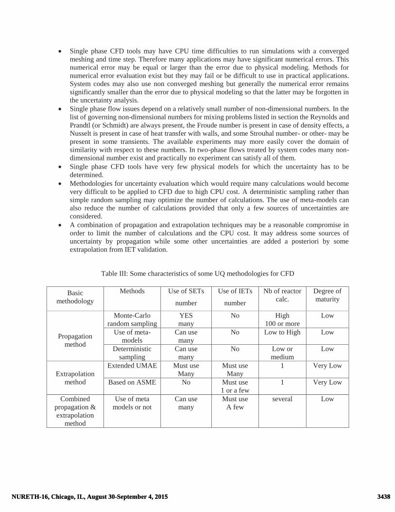
� Single phase CFD tools may have CPU time difficulties to run simulations with a converged meshing and time step. Therefore many applications may have significant numerical errors. This numerical error may be equal or larger than the error due to physical modeling. Methods for numerical error evaluation exist but they may fail or be difficult to use in practical applications. System codes may also use non converged meshing but generally the numerical error remains significantly smaller than the error due to physical modeling so that the latter may be forgotten in the uncertainty analysis.
� Single phase flow issues depend on a relatively small number of non-dimensional numbers. In the list of governing non-dimensional numbers for mixing problems listed in section the Reynolds and Prandtl (or Schmidt) are always present, the Froude number is present in case of density effects, a Nusselt is present in case of heat transfer with walls, and some Strouhal number- or other- may be present in some transients. The available experiments may more easily cover the domain of similarity with respect to these numbers. In two-phase flows treated by system codes many non-dimensional number exist and practically no experiment can satisfy all of them.
� Single phase CFD tools have very few physical models for which the uncertainty has to be determined.
� Methodologies for uncertainty evaluation which would require many calculations would become very difficult to be applied to CFD due to high CPU cost. A deterministic sampling rather than simple random sampling may optimize the number of calculations. The use of meta-models can also reduce the number of calculations provided that only a few sources of uncertainties are considered.
� A combination of propagation and extrapolation techniques may be a reasonable compromise in order to limit the number of calculations and the CPU cost. It may address some sources of uncertainty by propagation while some other uncertainties are added a posteriori by some extrapolation from IET validation.
Table III: Some characteristics of some UQ methodologies for CFD
Basic methodology
Methods Use of SETs
number
Use of IETs
number
Nb of reactor calc.
Degree of maturity
Propagation
method
Monte-Carlo random sampling
YES many
No High 100 or more
Low
Use of meta-models
Can use many
No Low to High Low
Deterministic sampling
Can use many
No Low or medium
Low
Extrapolation method
Extended UMAE Must use Many
Must use Many
1 Very Low
Based on ASME No Must use 1 or a few
1 Very Low
Combined propagation & extrapolation
method
Use of meta models or not
Can use many
Must use A few
several Low
3438NURETH-16, Chicago, IL, August 30-September 4, 2015 3438NURETH-16, Chicago, IL, August 30-September 4, 2015
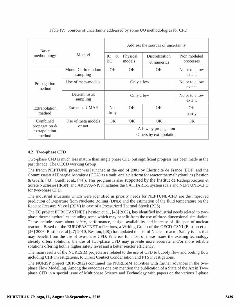
Table IV: Sources of uncertainty addressed by some UQ methodologies for CFD
Basic methodology
Method
Address the sources of uncertainty
IC & BC
Physical models
Discretization & numerics
Non modeled processes
Propagation method
Monte-Carlo random sampling
OK OK OK No or to a low extent
Use of meta-models Only a few No or to a low extent
Deterministic sampling
Only a few No or to a low extent
Extrapolation method
Extended UMAE Not fully
OK OK OK partly
Combined propagation & extrapolation
method
Use of meta models or not
OK OK OK OK
A few by propagation Others by extrapolation
4.2 Two-phase CFD
Two-phase CFD is much less mature than single phase CFD but significant progress has been made in the past decade. The OECD working Group The french NEPTUNE project was launched at the end of 2001 by Electricité de France (EDF) and the Commissariat à l'Energie Atomique (CEA) as a multi-scale platform for reactor thermalhydraulics (Bestion & Guelfi, [43], Guelfi et al., [44]). This program is also supported by the Institut de Radioprotection et Sûreté Nucléaire (IRSN) and AREVA-NP. It includes the CATHARE-3 system scale and NEPTUNE-CFD for two-phase CFD. The industrial situations which were identified as priority needs for NEPTUNE-CFD are the improved prediction of Departure from Nucleate Boiling (DNB) and the estimation of the fluid temperature on the Reactor Pressure Vessel (RPV) in case of a Pressurized Thermal Shock (PTS) The EC project EUROFASTNET (Bestion et al., [45] 2002), has identified industrial needs related to two-phase thermalhydraulics including some which may benefit from the use of three-dimensional simulation. These include issues about safety, performance, design, availability and increase of life span of nuclear reactors. Based on the EUROFASTNET reflections, a Writing Group of the OECD-CSNI (Bestion et al. [46] 2006, Bestion et al [47] 2010, Bestion, [48]) has updated the list of Nuclear reactor Safety issues that may benefit from the use of two-phase CFD. Whereas for most of these issues the existing technology already offers solutions, the use of two-phase CFD may provide more accurate and/or more reliable solutions offering both a higher safety level and a better reactor efficiency. The main results of the NURESIM projects are related to the use of CFD to bubbly flow and boiling flow including CHF investigations, to Direct Contact Condensation and PTS investigations. The NURISP project (2010-2012) continued the NURESIM activities with further advances in the two-phase Flow Modelling. Among the outcomes one can mention the publication of a State of the Art in Two-phase CFD in a special issue of Multiphase Science and Technology with papers on the various 2-phase
3439NURETH-16, Chicago, IL, August 30-September 4, 2015 3439NURETH-16, Chicago, IL, August 30-September 4, 2015

CFD approaches (Bestion et al, [49]), on adiabatic bubbly Flow (Krepper, et al, [50]), on boiling bubbly flow (Koncar et al., [51]), on annular mist flow (Anglart & Carraghiaur, [52]) and on stratified flow (Lucas et al., [53]). The NURESAFE project (2013-2015) is in progress following the NURESIM and NURISP activities with new advances in the two-phase Flow Modelling (see Chanaron et al. [54], Bestion et al. [55]). Due to the lower maturity of two-phase CFD tools the modeling will require probably several decades of R&D work. However first applications of such tools may already be envisaged provided that a rigorous methodology of modeling and validation is applied.
Figure 6: The general multi-step methodology for using two-phase CFD The general method of work illustrated in Figure 5 was proposed (Bestion et al [48]) when using two-phase CFD for safety issues with successive steps:
1. Identification of all important flow processes 2. Main modeling choices
• 2.1 Selecting a Basic model • 2.2 Filtering turbulent scales and two-phase intermittency scales • 2.3 Treatment of interfaces
3. Selecting closure laws • 3.1 Modeling interfacial transfers • 3.2 Modeling turbulent transfers • 3.4 Modeling wall transfers
4. Verification 5. Validation
If the CFD tool is used in the context of a safety demonstration, one may add a last step: 6. Uncertainty evaluation
3440NURETH-16, Chicago, IL, August 30-September 4, 2015 3440NURETH-16, Chicago, IL, August 30-September 4, 2015

The general steps of Figure 1 are still present. One main difference with system codes is that many modelling options are available and that the choice of a consistent set of options for the number of fields, the space and time filtering and the treatment of interfaces is not straightforward and requires a special attention. A very specific expertise is required and such CFD tools still have a limited number of expert users.
4.3 Two-phase CFD application to boiling flows
First applications of CFD to two-phase flow were developed for dispersed flows, including solid particle flows, droplet flows, and bubbly flows. CHF investigations with CFD was one major work package of the NURESIM, NURISP and NURESAFE European Projects of the 6th and 7th European Framework program (www.nuresim.com). A review of the available experimental data relative to boiling bubbly flow for DNB investigations of relative to annular-mist flow for Dry-out investigations was made and presented by D. Bestion et al [56]. It appears that the bubbly flow modelling still encounters some specific difficulties particularly for significant void fraction, when the bubble size is not very small, and when the bubble size is not uniform. Classical two-fluid modelling is extensively used. It requires a specific modelling effort for:
� the modelling of turbulence effects on momentum and heat transfers and on bubble dispersion � the use of transport equation(s) to characterize the bubble size or bubble size distribution. � the modelling of forces acting on the bubbles such as drag and virtual mass forces, lift and turbulent
diffusion forces � Interfacial transfers of heat, mass and momentum � boundary conditions which require wall functions for momentum and energy equations including
bubble generation at the wall in case of boiling flows Today available models may predict boiling flow in heated channels with a reasonable accuracy. The prediction of average void fraction in a cross section of a channel is not more precise than 1D models when comparing to BFBT or PSBT benchmark tests performed for BWR and PWR rod bundles. But CFD provides additional information and geometrical effects in more complex geometry are possibly predicted rather than treated by tuning factors in 1D models. Application to DNB prediction reaches a 10% accuracy in heated circular pipes and this may be sufficient to allow parametric studies for fuel design. A similar situation exists for annular-mist flow and dry-out prediction.
4.4 Two-phase CFD application to PTS
Pressurized Thermal Shock (PTS) in some two-phase scenarios is part of the activity performed by the NURESIM, NURISP and NURESAFE projects with application of two-phase CFD. Pressurized Thermal Shock may occur in a Pressurized Water Reactor (PWR) when overcooling of the pressure vessel wall in case of irradiation induced loss of ductility may lead to failure. Small Break LOCA scenarios exist with an Emergency Core Cooling System ECCS injection in a partially or totally uncovered cold leg where the main heat source to the liquid is due to steam condensation in the cold leg and in the top of the downcomer. Condensation is mainly dependent on the interfacial structure and on the turbulent mixing in the liquid phase. The investigation focuses on slow transients following a SBLOCA with the rather simple interfacial structure of a stratified flow in the cold leg. The main objective is to predict the liquid temperature field which depends mainly on interfacial heat and mass transfer related to direct contact condensation of steam on a sub-cooled liquid and on the turbulence diffusion within the liquid. Many research works support that turbulence behavior near the interface plays a dominant role for the interfacial transfers. For ECC injection cases, the turbulence mainly comes from the impact of the water jet and shear at the wall and at the gas-liquid interface. Thus, as a first step to simulate such scenarios, separate effects in simple geometry have to be investigated, i.e., interfacial friction and turbulence production, interfacial heat transfer, turbulence in a water pool induced by a water jet, in order to establish and validate the developed models in this paper. The identification of all basic flow processes was made and many phenomena were identified. In the ECCS jet area:
3441NURETH-16, Chicago, IL, August 30-September 4, 2015 3441NURETH-16, Chicago, IL, August 30-September 4, 2015

1. Instabilities of the jet from ECC injection, 2. Condensation on the jet itself before mixing 3. Entrainment and migration of steam bubbles below the water level 4. Turbulence production below the jet
In the stratified flow in cold leg: 5. Interfacial transfer of momentum at free surface 6. Interfacial transfer of heat & mass at free surface 7. Turbulence production in wall shear & in interfacial shear layers 8. Heat transfers with cold leg and RPV walls 9. Effects of turbulent diffusion upon condensation 10. Interactions between interfacial waves, interfacial turbulence production and condensation 11. Effects of temperature stratification upon turbulent diffusion 12. Influence of non-condensable gases on condensation
In the downcomer: 13. Flow separation or not in dowcomer at cold leg nozzle 14. Heat transfers with the walls
The phenomena 4, 6, 10, and 13 are ranked as dominant phenomena. A rather simple interface structure is encountered in the cold leg of the reactor with a stratified flow having a flat or wavy interface. Only the entrainment of bubbles below the free surface by the ECCS jet may give a somewhat complex interface structure but limited to a small region of the flow. The turbulent diffusion within the liquid phase controls the condensation efficiency and a high turbulent mixing due to the ECCS jet impingement is the main source of turbulence. The k-� model n, the Rij- model and LES models were tested and compared. Interfacial transfers of heat and momentum (friction force) on the free surface require a specific modeling taking into account the space filter scale imposed by the meshing: the transfer coefficients may depend on the distance to the interface in the same way as the distance to the wall is used in wall functions. Difficulties are encountered for modelling turbulence and heat transfers at the free surface in case of high interfacial shear and presence of waves. The presence of such waves must be predicted and the effect on interfacial transfers must be modelled. A status of the modelling was reported at end of the NURISP project (Lucas et al, [53]). Such a modelling was found rather satisfactory at least for the momentum interfacial transfers and for turbulence prediction. Coste developed a specific “Large Interface” model (Coste et al, [57,58,59]) where the free surface is localized from the void fraction gradient and interfacial transfers are treated with an extrapolation of the wall function approach. It was applied to air-water flow and condensing stratified flows. A non-isotropic interfacial friction was necessary at the free surface. Fig 7 shows predictions of steam-water tests in the TOPFLOW-PTS experiment. The calculations predicted reasonably well the liquid temperature profile and sensitivity tests to the mesh size showed a good mesh convergence with a reasonable number of meshes which allows the model to be applicable to reactor simulations. The quality of prediction are so good that this 2-phase CFD application to a safety issue appears to be very close to the success.
3442NURETH-16, Chicago, IL, August 30-September 4, 2015 3442NURETH-16, Chicago, IL, August 30-September 4, 2015

Figure 7: TOPFLOW-PTS test SSSW 3-17 simulation with NEPTUNE-CFD (from Coste & Merigoux, 2014) with sensitivity to the meshing
4.5 Two-phase CFD for all flow regimes
Modelling all two-phase flow regimes with two-phase CFD is a difficult challenge as explained by Bestion [60]. Two-phase CFD capabilities have progressed for dispersed bubbly or droplet flow and separate-phase flow but much less experience exists on more complex flow regimes which combine the existence of dispersed fields with the presence of large interfaces such as a free surface or a film surface. The first difficulty is to identify the various types of local flow configuration. It was shown that a 4-field model has much better capabilities than a two-fluid approach to identify most complex regimes. Then the choice of a space averaging, seems more appropriate than the time averaging if a good accuracy is expected or if time fluctuations in intermittent flow have to be predicted. An important effort is required to model all interactions between sub-filter phenomena and the transfers from the sub-filter domain to the simulated domain. The main difficulties are expected in modelling the transfer of sub-filter interfaces to predicted interfaces and the multiple effects of sub-filter deformations of large interfaces on inter-field transfers. A combination of field averaging for dispersed droplets and small bubbles with an Interface tracking technique for large interface is being developed in parallel in the NEPTUNE-CFD code in TransaT code and in CFX within the NURESAFE project
4.6 The benefit of a multi-scale approach of reactor thermalhydraulics
From the Direct Numerical Simulation to system codes several modelling scale exist which bring a benefit to the analysis of LWR Thermalhydraulics (see Bestion, [61, 62]). Multiscale thermalhydraulic analyses are performed in the NURESIM, NURISP and NURESAFE projects (Bestion et al. [63]).The case of the reflooding may illustrate the added value of the multiscale approach. CFD simulations of the flow with superheated steam and droplets in the dry zone of the core during a reflooding process may bring additional information which is currently not accessible by available measuring techniques. CFD may predict the transverse profiles of velocity, temperature,
3443NURETH-16, Chicago, IL, August 30-September 4, 2015 3443NURETH-16, Chicago, IL, August 30-September 4, 2015

and void fraction, and these figures can then be used to evaluate the error made by simplifications and assumptions of current models of system codes. The steam-to-droplet heat flux qvi plays a very important role in the process, by transporting the heat received from the rods to the droplets. Present system codes do not model profile effects, even though the difference between the space-averaged function <qvi(Xj)> which is to be modeled and the function of the space-averaged flow parameters qvi(<Xj>) which is used in the closure law can often be quite large. CFD may allow for the development of a model which can account for these profile effects. CFD simulations may also determine the influence of the droplets on the wall-to-steam convective heat transfer coefficient. CFD simulations associated with Lagrangian Particle Tracking (LPT) of droplets may also bring information on the frequency of non-rewetting drop impact on the walls. If experimental data or pseudo-DNS simulations provide the power exchange for every non-rewetting drop impact, a model may be derived for the dispersed flow film-boiling heat transfer. Pseudo-DNS or LES with simulated interfaces can also be used to develop physically based models for the following processes:
• Creation of droplets by film splitting at a quench front, with prediction of the drop size • Droplet splitting by a non-rewetted spacer grid • Droplet entrainment from liquid films along rewetted spacer grids, with prediction of the drop size
A multi-scale approach is necessary at every step of the solution of a complex problem. During a PIRT, system level, component level and various scales of processes have to be considered. During the ranking of processes, the scaling of experiments, the selection of simulation tools, a multi-scale approach is applied. Simulations tools at macro-scale (system codes) meso-scale (CFD) and micro-scale (DNS) may be used at every step. The relatively recent arrival of CFD and DNS tools in the nuclear thermalhydraulics community brought a culture on turbulence and enriched the analysis of complex flows. New experiments with new experimental techniques were developed which also provided a better knowledge of small scale local processes. The confrontation of simulation tools with experimental data at various scales is probably the best way to develop the understanding of the thermalhydraulics.
5. SUMMARY CONCLUSIONS AND RECOMMENDATIONS
On the methodology for solving a complex reactor issue
To solve a complex reactor thermalhydraulic issue, several tools and methods are required. None of the existing numerical simulation tool can be used as a black box particularly in case of a safety analysis which requires a sufficient level of reliability and accuracy of the prediction. The non-linear character of fluid dynamics and the multiplicity of scales at which important phenomena occur makes the problem complex. Exact equations cannot be solved and simplified equations exist but they one must demonstrate that the simplifications are justified in the particular case of interest. The first step is the identification of the dominant processes governing or influencing the figure of merit or safety criterion. Dimensional analysis applied to various balance equations allows to ranking processes from large scale to smaller scale and to define the scaling to apply in integral test facilities to simulate most important processes. However simulation of the reactor situation in scaled IETs involves some distortion of some processes. This makes the extrapolation from the experiment to the reactor difficult or even impossible. This dimensional and scaling analysis also identifies the type of equations and models which may be used to simulate numerically the reactor issue. Most LWR issues require a system code to simulate the complex interactions between reactor components. These codes must be verified and validated in the domain of application. The validation should cover all dominant processes and should predict the scale effect up to
3444NURETH-16, Chicago, IL, August 30-September 4, 2015 3444NURETH-16, Chicago, IL, August 30-September 4, 2015

the reactor scale. The scalability or scale-up capability of the code also requires that some SETs which scale properly processes that are distorted in IETs and that system codes can predict them correctly. However system codes can themselves distort some phenomena when some simplifications of the physical model is not justified in the case of interest. This is not acceptable for a dominant process but may be acceptable for medium rank processes provided that the impact on the transient is taken into account in the code uncertainty quantification. Uncertainty quantification of reactor simulation requires that all sources of uncertainty are taken into account: reactor input parameters such as IC- BC and material properties, closure laws, numerical error, and distorted or non-modelled processes. The quantification of uncertainty on closure laws should be validated on the largest possible data base and uncertainty due to distortions or non-modelled phenomena should be addressed. When system codes are used, attention should be paid to the following limitations:
� Many processes depend a lot on the geometry and the models may be valid only for one specific geometry: any new geometry requires validation and may need adjustment of the model
� Closure laws may have a large uncertainty due to some simplification of the physics, or to the presence of non-modelled processes (e.g. coalescence which affects bubble size and then interfacial drag)
� Closure laws may have a large uncertainty because they have a low influence on the most common transients and no big effort was spent to improve them. In a new transient, if the influence is larger, a better and more accurate model may be required. For example condensation at ECCS injection have not a very important effect on LOCAs. When investigating PTS, a more accurate model was developed for the CATHARE code with a better scalability ( Gaillard et al., [64])
� Local 3-D effects such as buoyancy driven 3D circulation cannot be well represented by 0-D and 1-D models of the system effects.
� Many closure laws have a high degree of empiricism which makes extrapolation beyond the validated domain hazardous.
When performing the uncertainty quantification, the following recommendations can be drawn from the past benchmarks:
� Uncertainties on closure laws of system codes should be validated on the largest possible SET data base
� Uncertainty due to distortions or non-modelled phenomena may be estimated and partly validated using SETs and IETs relative to the domain of simulation.
Single-phase CFD is now a mature technology which may be used for safety analyses of some issues where 3D mixing phenomena play a dominant role. BPGs exist which may be further improved, assessment requirements may be more precisely defined but the main effort should be devoted to UQ of CFD. Extensions of the methods used for system codes to CFD are possible but CPU cost may be a main difficulty for some time. Several approaches may be benchmarked and a special attention should be paid to uncertainty due to numerics and nodalization which play a more important role than in system codes. Two-phase CFD made significant progress in the past decade for some applications to boiling flow, DNB, Dry-out, stratified flow, DCC, PTS, where there are either dispersed flow or separate phase flow regimes. Further modelling efforts are necessary to progress in the capability to model all flow regimes and flow regime transitions. Two-phase CFD is already useful as a support to design (fuel optimization) and may be used as a support to other methods for safety demonstration. It is also a tool for improving the knowledge on small scale processes and may be envisaged as a tool for improving more macroscopic models. All steps of the methodology for solving such complex reactor issues require a high level of expertise. PIRT requires a good culture on the phenomenology. Scaling requires a good control of the various ways to write equations from basic principles. Code application requires a good knowledge of capabilities and limitations of the codes. The use of codes cannot be in any case an alternative to the physical analysis. However codes
3445NURETH-16, Chicago, IL, August 30-September 4, 2015 3445NURETH-16, Chicago, IL, August 30-September 4, 2015

may be useful tools at every step; sensitivity tests may help in the PIRT exercise, pre-calculations of IETs may check the scaling rules, scaling-up to reactor scale may be better done through a code provided that some requirements for scalability are met. The main concern for future is to find activities which help preserving the sufficient level of expertise. At the end an important part of the prediction comes from what has been learnt from experimental data and a minor part from applying equations expressing the first principles. Further progress will come first from new experimental data analysis together with a multi-scale approach of simulation. Recommendations for future activities in thermalhydraulics
Weaknesses of system codes which were identified may be progressively reduced by implementing models for some phenomena which are not treated in current 6-equation models, including multi-field modelling, dynamic modelling of interfacial area, improved porous-3D modelling and coupling with CFD. The main condition for progressing is to start by performing new experiments to investigate the processes, to develop and validate the new models. The following experiments are necessary for improving system codes:
� Entrainment and deposition of droplets particularly with geometrical effects in core, upper plenum, hot legs and SG inlet
� Core thermalhydraulic experiment to identify the interface structure, to define a flow regime map and to measure relaxation time scales for flow regime in a LWR core
� Core thermalhydraulic experiment to investigate radial transfers by crossflows, by diffusion and dispersion and to determine wall friction and interfacial friction tensors
These experiments are useful not only for development of new models but also for validation of present models and foe a better evaluation of uncertainties of current codes. Multiscale simulation and development of advanced 2-phase CFD simulation tools should be further developed with a strong coordination between experiment and modelling and between the various scales. Among the main challenges in this field one may identify:
� Developing and applying upscaling techniques to derive models from microscopic scale simulations for more macroscopic models
� Developing a two-phase CFD model for all flow regimes � Using CFD for predicting singular pressure losses, CCFL in complex geometry � Using DNS and CFD to finally identify the dominant mechanism leading to DNB
Apart from R&D, efforts to keep a sufficient level of expertise and to attract young people to reactor thermalhydraulics may include:
� Multiscale simulation and development of advanced simulation tools including RANS CFD, LES and DNS tools in both 1-phase and two-phase conditions is an efficient way of attracting many young researchers
� Specific courses should be devoted to train to the PIRT exercise, to the scaling activities, and to the uncertainty quantification
� Specific courses should be devoted to train system code users to suspect and find an error in a input deck in view of reducing the User Effect
� More detailed code documentation of system codes should list all simplifying assumptions, clearly identify the domain of validation of each model, the uncertainty of each closure law, and an evaluation of the sensitivity to the geometry
� Revisiting models of current system codes to check the scalability of every closure laws might be a good way to develop the engineer judgment on code capabilities and limitations
3446NURETH-16, Chicago, IL, August 30-September 4, 2015 3446NURETH-16, Chicago, IL, August 30-September 4, 2015

ACKNOWLEDGEMENTS
The author is grateful to CEA, AREVA, EDF and IRSN who finance the NEPTUNE project for a multi-scale thermalhydraulic platform including the CATHARE code and the NEPTUNE-CFD code, to all the members of the NEPTUNE project team, to the European Commission who financed the NURESIM, NURISP and NURESAFE projects, to all the contributors to these projects, and to OECD-NEA which plays an important role in the analysis of accidents through the WGAMA working Group and to the members of the CFD task groups which produced valuable documents to promote the use of CFD for nuclear reactor safety.
REFERENCES
[1] G. E. Wilson, B. E. Boyack “The role of the PIRT process in experiments, code development and code applications associated with reactor safety analysis”, Nuclear Engineering and Design, 186, 23–37 (1998).
[2] N. Zuber, 1991. Appendix D: a hierarchical, two-tiered scaling analysis, an integrated structure and scaling methodology for severe accident technical issue resolution. US Nuclear Regulatory Commission, Washington, DC 20555, NUREG/ CR-5809, November 1991
[3] N. Zuber, G. E. Wilson, M. Ishii, W. Wulff, B. E. Boyack, A. E. Dukler, P. Griffith, J. M. Healzer, R. E. Henry, J. R. Lehner, S. Levy, F. J. Moody, M. Pilch, B. R. Seghal, B. W. Spencer, T. G. Theofanous, J. Valente “An integrated structure and scaling methodology for severe accident technical issue resolution: development of methodology”, Nuclear Engineering and Design, 186, 1–21 (1990)
[4] N. Zuber, W. Wulff, U.S Rohatgi, I. Catton, 2005. Application of Fractional Scaling Analysis (FSA) to Loss of Coolant Accidents (LOCA), Part 1: Methodology Development, Int. Top. Meet. on Nuclear Reactor Thermal Hydraulics (NURETH-11), Avignon (F).
[5] W. Wulff, N. Zuber, Rohatgi, U.S., Catton, I. 2005. Application of Fractional Scaling Analysis (FSA) to Loss of Coolant Accidents (LOCA), Part 2: System level scaling for System Depressurization, Int. Top. Meet. on Nuclear Reactor Thermal Hydraulics (NURETH-11), Avignon (F).
[6] I. Catton, W. Wulff, N. Zuber, Rohatgi, U.S., 2005. Application of Fractional Scaling Analysis (FSA) to Loss of Coolant Accidents (LOCA), Part 3: Component level scaling for Peak Clad Temperature, Int. Top. Meet. on Nuclear Reactor Thermal Hydraulics (NURETH-11), Avignon (F).
[7] M. Valette , J. Pouvreau, D. Bestion, P. Emonot, Revisiting Large Break LOCA with the CATHARE 3 Three Field Model, Nuclear Engineering and Design, Volume 241, Issue 11, November 2011, Pages 4487-4496
[8] F. Barre, D. Bestion, Validation of the Cathare system code for nuclear reactor thermalhydraulics, 1995 ASME & JSME Fluid Engineering Conference, 13-18 Aug. 1995, Hilton Head, South Carolina
[9] D. Bestion, F. Barre, B. Faydide, Methodology, status and plans for development and assessment of the Cathare code, OECD/CSNI Workshop on transient thermalhydraulic and neutronic codes requirements, Annapolis, USA 5-8 novembre 1996
[10] D. Bestion, F. Barre, Status of thermalhydraulic modelling and assessment: open issues, OECD/CSNI Workshop on transient thermalhydraulic and neutronic codes requirements, Annapolis, USA 5-8 novembre 1996
[11] D. Bestion, The physical closure laws in the Cathare code, Nuclear. Engineering. & Design, 124 (1990) 229-245
[12] A. de Crécy, “Determination of the uncertainties of the constitutive relationships of the CATHARE 2 code”, M&C 2001, Salt Lake City, Utah, USA, September 2001.
[13] A. de Crécy, P. Bazin, “Quantification of the Uncertainties of the Physical Models of CATHARE “”, BE2004, Washington D.D., USA, November 2004.
3447NURETH-16, Chicago, IL, August 30-September 4, 2015 3447NURETH-16, Chicago, IL, August 30-September 4, 2015

[14] B. Chexal, G. Lellouche, A full range drift-flux correlation for vertical flows (Revision 1), EPRI Report NP-3989-SR, USA, 1986.
[15] D. Bestion, G. Serre, On the modelling of two-phase Flow in horizontal legs of a PWR, Nuclear Engineering and Technology, Vol.44 No.8 December 2012
[16] D. Bestion, L. Matteo, Scaling considerations about LWR Core thermalhydraulics, NURETH-16, Chicago, USA, August 30-sept 5, 2015
[17] RELAP5/MOD3 Code Manual Volume I: Code structure, system models and solution procedure, NUREG/CR-5535, March 1998
[18] TRACE V5.0, THEORY MANUAL Field Equations, Solution Methods, and Physical Models, 2007 [19] D. Bestion, Capabilities and limitations of thermalhydraulic codes, CSNI Specialist Meeting on
Transient Two Phase Flow, Aix en Pce Avril 1992 [20] Proceedings of OECD/CSNI Specialist Meeting on Transient Two-Phase Flow - System
Thermalhydraulics, Aix-En-Provence (F), 1992 [21] Proceedings of OECD/CSNI Workshop on Transient Thermal-Hydraulic and Neutronic Codes
Requirements, 5-8 November 1996, Annapolis, Md, USA, NUREG/CP-0159, NEA/CSNI/R(97)4 [22] OECD/CSNI, 2000, Proceedings of “OECD/CSNI Workshop on Advanced Thermal-Hydraulic and
Neutronic Codes: Current and Future Applications”, Barcelona (E). [23] R. Freitas, D. Bestion, On the prediction of the flooding phenomenon with the Cathare code, 6th Int.
Topical Meeting on Nuclear Reactor Thermalhydraulics, NURETH 6, Grenoble, Oct.5-8, 1993 [24] D. Bestion, G. Serre, Transport of interfacial area in system codes: status and perspectives, 15th
International Topical Meeting on Nuclear Reactor Thermalhydraulics, NURETH-15, Pisa, Italy, May 12-15, 2013
[25] D. Bestion, Validation data needs for CFD simulation of two-phase flow in a LWR core, CFD4NRS-5, Zurich, September 2014, to be published in a Special issue of Nuclear Engineering and design devoted to CFD4NRS-5, 2015
[26] I. Dor, M. Chandesris, P. Germain and A. Ruby, CATHARE 3D module- from CATHARE 2 V2.5_3 to CATHARE 3 V1.0, NURETH-15, Pisa, Italy, May 12-15, 2013
[27] C. Morel and P. Boudier, “Validation of the CATHARE code against PERICLES 2D reflooding tests”, Proceedings of the 9th NURETH, San Francisco, USA, 1999.
[28] C. Morel, D. Bestion, Validation of the Cathare code against Pericles 2D boil up tests, NURETH-9, Oct 99, San Francisco
[29] I. Dor, P. Germain, Core radial power profile effect during Reflooding , Validation of CATHARE2 3D module using SCTF tests, NURETH-14, Toronto, Canada, September 25-30, 2011
[30] M. Chandesris, M. Mazoyer, G. Serre and M. Valette, “Rod bundle thermalhydraulics mixing phenomena: 3D analysis with CATHARE 3 of various experiments”, Proceedings of the 15th International Topical Meeting on Nuclear Reactor Thermal-hydraulics (NURETH15), Pisa, Italy, May 2013.
[31] B. Boyack et al., “Quantifying Reactor Safety Margins, Application of Code, Scaling, Applicability, and Uncertainty Evaluation Methodology to a Large Break, Loss-of- Coolant Accident,” NUREG/CR-5249, USNRC, December 1989.
[32] B. Boyack et al., “An Integrated Structure and Scaling Methodology for Severe Accident Technical Issue Resolution,” Draft NUREG/CR-5809, USNRC, November 1991.
[33] J. NED, Special Issue, 1990, Vol 119, 1, devoted to CSAU. [34] H. Glaeser, E. Hofer, M. Kloos, T. Skorek, “Uncertainty and Sensitivity Analysis of a Post-Experiment
Calculation in Thermals Hydraulics”, Reliability Engineering and System Safety, Vol. 45, pp. 19-33, 1994
3448NURETH-16, Chicago, IL, August 30-September 4, 2015 3448NURETH-16, Chicago, IL, August 30-September 4, 2015

[35] F. D'Auria, N. Debrecin, G.M. Galassi, 1995, Outline of the Uncertainty Methodology based on Accuracy Extrapolation (UMAE). Nuclear Technology, 109, 1, 21-38.
[36] F. D’Auria,W. Giannotti, Development of Code with capability of Internal Assessment of Uncertainty, J. Nuclear Technology, Vol 131, No. 1, pages 159-196 – Aug. 2000.
[37] A. Petruzzi, D’Auria, F. 2008. Approaches, Relevant Topics, and Internal Method for Uncertainty Evaluation in Predictions of Thermal-Hydraulic System Codes, J. Science and Technology of Nuclear Installations, Vol 2008, Art. ID 325071
[38] OECD/CSNI, 1998. Report of the Uncertainty Methods Study for advanced best estimate thermal-hydraulic code applications. Vol I & II. OECD/CSNI Report NEA/CSNI/R(97)35, Paris
[39] A. de Crécy, P. Bazin (Editors), H. Glaeser, T. Skorek, J. Joucla, P. Probst, B. Chung, D.-Y. Oh, M. Kynck, R. Pernica, J. Macek, R. Meca, R. Macian, F. D’Auria, A. Petruzzi, M. Perez, F. Reventos, K. Fujioka, Bemuse Phase III Report, Uncertainty and Sensitivity Analysis of the LOFT L2-5 Test, OECD/CSNI Report NEA/CSNI/R(2007)4, October 2007
[40] Nuclear Safety NEA/CSNI/R(2014)14 [41] B.L. Smith, U. Bieder, E. Graffard, M. Heitsch , M. Henriksson,T. Höhne, E. Komen, J. Mahaffy, F.
Moretti, T. Morii, P. Mühlbauer, U. Rohde, M. Scheuerer, C.-H. Song, G. Zigh, M. Andreani, D. Bestion, F. Ducros, M. Houkema, D. Lucas, F. Menter, T. Watanabe, “Assessment of Computational Fluid Dynamics (CFD) for Nuclear Reactor Safety Problems”, OECD Nuclear Energy Agency, Technical Report, NEA/CSNI/R(2007)13, Jan. 2008
[42] J. Mahaffy (ed.), Best practice guidelines for the use of CFD in nuclear reactor safety applications, OECD, Nuclear Energy Agency, Technical Report, NEA/CSNI/R(2007)5, April 2007.
[43] D. Bestion, A. Guelfi, « Status and perspective of two-phase flow modelling in the NEPTUNE Multiscale thermal-hydraulic platform for nuclear reactor simulation », Nuclear Engineering and Technology, 2005, Vol. 16, Nos 1-3, pp 1-5.
[44] A. Guelfi, D. Bestion, M. Boucker, P. Boudier, P. Fillion, M. Grandotto, J.M. Herrard, E. Hervieu, P. Peturaud, NEPTUNE A new Software Platform for advanced Reactor Thermalhydraulics, Nuclear Science and Engineering, 156, 282-324, 2007 [45] D. Bestion, A. Latrobe, H. Paillere, A. Laporta, V. Teschendorff, H. Staedtke, N. Aksan, F. D’Auria, J.
Vihavainen, P. Meloni, G. Hewitt, J. Lillington, B. Mavko, A. Prosek, J. Macek, M. Malacka, F. Camous, F. Fichot, D. Monhardt, 2002, European Project for Future Advances in Science and Technology for Nuclear Engineering Thermal-Hydraulics (EUROFASTNET), Final Report, 2002
[46] D. Bestion, H. Anglart, B.L. Smith, J. Royen, M. Andreani, J.H. Mahaffy, F. Kasahara, E. Komen, P. Mühlbauer, T. Morii, M. Scheuerer, E. Laurien, T. Watanabe, A. Dehbi, Extension of CFD Codes to Two-Phase Flow Safety Problems, NEA/SEN/SIN/AMA(2006)2
[47] Anglart, J. Mahaffy, D. Lucas, C.H. Song, M. Scheuerer, G. Zigh, M. Andreani, F. Kasahara, M. Heitsch, E. Komen, F. Moretti, T. Morii, P. Mühlbauer, B.L. Smith, T. Watanabe, Extension of CFD Codes to Two-Phase Flow Safety Problems, NEA-CSNI-R(2010)2
[48] D. Bestion, Extension of CFD Code application to Two-Phase Flow Safety Problems, Nuclear Engineering and Technology, VOL.42 NO.4 August 2010
[49] D. Bestion, P. Coste, B. Niceno, S. Mimouni, Two-phase CFD: the various approaches and their applicability to each flow regime, Multiphase Science and Technology, Volume 23, Issue 2-4, 2011
[50] E. Krepper, C. Morel, B. Niceno, P. Ruyer, CFD modeling of adiabatic bubbly flow, Multiphase Science and Technology, Volume 23, Issue 2-4, 2011
[51] B. Končar, C. Morel, S. Mimouni, L. Vyskocil, G. Hazi, M. C. Galassi, CFD modeling of boiling bubbly flow for DNB investigations, Multiphase Science and Technology, Volume 23, Issue 2-4, 2011
[52] H. Anglart and D. Caraghiaur, 2011, CFD modeling of boiling annular-mist flow for Dry-out investigations , Multiphase Science and Technology, Volume 23, Issue 2-4, 2011
3449NURETH-16, Chicago, IL, August 30-September 4, 2015 3449NURETH-16, Chicago, IL, August 30-September 4, 2015

[53] D. Lucas, P. Coste, T. Höhne, D. Lakehal, Y. Bartosiewicz, D. Bestion, M. Scheuerer, M.C. Galassi, CFD modeling of free surface flow with and without condensation, Multiphase Science and Technology, Volume 23, Issue 2-4, 2011
[54] B. Chanaron, S. Kliem, D. Lakehal, D. Bestion, V. H. Sanchez, N. Crouzet, The European NURESAFE Simulation Project For Reactor Safety, to presented at ICONE-22, Praha, July 2014
[55] D. Bestion, D. Lakehal, N. Tregoures, D. Lucas, H. Anglart, B. Niceno, G. Hazi, L Vyskocil, Multiscale thermalhydraulic analyses performed in the NURESAFE project, to be presented at ICONE-22, Praha, July 2014
[56] Bestion, D., Anglart, H., Péturaud, P., Smith, B., Krepper, E., Moretti, F., Macek J.: « Review of available data for validation of NURESIM two-phase CFD software applied to CHF investigations », NURETH-12, Sheraton Station Square, Pittsburgh, Pennsylvania USA, 30 Septembre-4 Octobre 2007
[57] P. Coste, J. Laviéville, J. Pouvreau, C. Baudry, M. Guingo, A. Douce, validation of the large interface method OF NEPTUNE_CFD 1.0.8 for PTS applications, CFD4NRS-3, Washington-DC, sept 2010
[58] P. Coste, J. Laviéville, J. Pouvreau, C. Baudry, M. Guingo, “Validation of the large interface method of NEPTUNE_CFD 1.0.8 for pressurized thermal shock applications”, Nuclear Engineering and Design, DOI: 10.1016/ j. nucengdes. 2011. 08. 066, 2011
[59] P. Coste and N. Mérigoux, Two-phase CFD validation: TOPFLOW-PTS steady-state steam-water tests 3-16, 3-17, 3-18, 3-19 to be presented at CFD4NRS-5, Zurich, Sep. 2014
[60] D. Bestion, The difficult challenge of a two-phase CFD model for all flow regimes, CFD4NRS-4, Dae Jeon, Korea, September 10-12, 2012
[61] D. Bestion, From the Direct Numerical Simulation to system codes – Perspective for the Multi-scale analysis of LWR Thermalhydraulics, Nuclear Engineering and Technology, VOL.42, NO.6, December 2010c
[62] D. Bestion, D. Lucas, H. Anglart, B. Niceno, L. Vyskocil, Multiscale thermalhydraulic analyses performed NURESIM and NURISP projects, 18th International Conference on Nuclear Engineering ICONE20, July 30-August 12, 2012, Anaheim, California, USA
[63] D. Bestion, Status and perspective for a multiscale approach to Light Water reactor thermalhydraulic simulation, NURETH 14 topical Issue of Nuc. Eng. and Des., 2012c
[64] P. Gaillard, D. Bestion, I. Dor, P. Germain, F. Moutin, The CATHARE Code condensation modelling confronted to the TOPFLOW-PTS steady-state experiments, NURETH-16, Chicago, Aug. 29-Sept 5, 2015, USA
3450NURETH-16, Chicago, IL, August 30-September 4, 2015 3450NURETH-16, Chicago, IL, August 30-September 4, 2015