systems and methods for managing assets using an interactive
TRANSCRIPT

United States Patent
US007058154B1
(12) (10) Patent N0.: US 7,058,154 B1 Stark et a]. (45) Date of Patent: Jun. 6, 2006
(54) SYSTEMS AND METHODS FOR MANAGING 5,875,110 A 2/1999 Jacobs ASSETS USING AN INTERACTIVE 5,930,315 A 7/1999 Morman et a1. DATABASE 6,122,239 A * 9/2000 Bodo et a1. ................. .. 369/59
6,421,571 B1 * 7/2002 Spriggs et a1. .............. .. 700/17
(75) Inventors: Randal Raymond Stark, Morgan Hill, FOREIGN PATENT DOCUMENTS CA (US); Steven Max Buckner, Gilroy, CA (US); Ahdee Quan Chan, JP 09044231 * 2/1997
Ranganath, San Jose, CA (US) “Nuclear device could monitor cooling tube cracking” AP,
(73) Assignee; General Electric Company, Morning Call; Allentown, Pa; Jul. 25, 1984.* schenectad NY US “Nimo aWaits OK on dela the NRC is considerin Whether y, ( ) y g
the utility can put off a reinspection at one of its Nuclear ( * ) Notice: Subject to any disclaimer, the term of this Power Plants”; Mary Hill’ The Post-Standard; Syracuse,
patent is extended or adjusted under 35 N.Y.; Oct. 30, 1998* U.S.C. 154(b) by 423 days. “Cracks pose threat to nuclear plant”; The Times, London;
Dec. 8, 1994.* (21) Appl. No.: 09/634,434 _ _
* cited by examlner
(22) Filed: Aug‘ 8’ 2000 Primary ExamineriWynn W. Coggins (51) I t Cl Assistant ExamineriR. E. Rhode, Jr.
Gn2'1 C 9/00 (2006 01) (74) Attorney, Agent, or F irmiArmstrong Teasdale LLP
(52) US. Cl. ..................................... .. 376/260; 228/102 (57) ABSTRACT (58) Field of Classi?cation Search ................ .. 369/59;
_ _ 700/17; 705/26’ 27; 7030} 711/111 The disclosed invention is a system and a method utilizing See aPPhCaUOn ?le for Complete Search hlstory- a Web-based interactive database to automate the process for
_ managing internal components of a plant. The system cap (56) References Clted tures all essential information and provides on-line up-to
U.S. PATENT DOCUMENTS
4,908,775 A * 3/1990 Palusamy et a1. ........... .. 702/34
5,311,562 A * 5/1994 Palusamy et a1. .. 376/215 5,331,579 A * 7/1994 Maguire et a1. ............. .. 703/2
5,768,142 A 6/1998 Jacobs 5,826,252 A 10/1998 Wolters, Jr. et a1.
date information upon request. The system provides valu able information to a customer to analyze the plant speci?c problem and offers inspection methods, mitigation methods and processes to resolve the problem.
74 Claims, 16 Drawing Sheets

U.S. Patent Jun. 6, 2006 Sheet 1 6f 16 US 7,058,154 B1
/ 20
DATABASE COMPUTER \ <—
14
/ 16 DATABASE
SERVER / /
sERvER
\ 14 12 COMPUTER /
/, FIG. 1

U.S. Patent
56
— 7.7
Jun. 6, 2006 Sheet 2 0f 16 US 7,058,154 B1
r12 1- _ _ _ _ _ _ — _ — _ — — — — — _ _|
_=E='“_ =5’ _ J l: I: [_
W E 1 H \_E : g g g Z. :4 APPLICATION DATABASE I
24 SERVER 16 SERVER |
LAN/WAN — i g 36 50 \
i I
46 3rd PA%CUSTOMERS % é " l
FIG. 2 \ 21

U.S. Patent Jun. 6, 2006 Sheet 3 6f 16 US 7,058,154 B1
i ‘i E A a K14
Client System Internals
Information System ere)
. ‘ I Background Information 96 Sub-Section (n1.s.s.) —/ |
Field History Information 98 Sub-Section (F.H.I.S.S.)
Sub-Section (I.I.S.S.) 10
_/
Mitigation Information 1 1 Sub-Section (M.I.S.S.) J
l1 Repair Information Sub-Section (R.I.S.S.)
l l I I I
: Inspection Information | I | | | |
Data Storage Devices I I
‘gL________;______________________ Collection Component 3
Tracking Component _ 66
Displaying Component _ 68
Receiving Component __ 7o
Accessing Component _ 72
Processing Component __ 76
Retrieving Compwem-C lizzzzzgizfxxi g; 80
Information Ful?llment Component
FIG. 3

U.S. Patent Jun. 6, 2006 Sheet 4 6f 16 US 7,058,154 B1
sset Management Welcome to the Asset Management Program.
Please choose one of the following plants:
[-310 [-320 0 Dresden 2 0 LaSalle 2
K312 [-324 0 Dressden 3 0 Quad Cities 1
r316 [328 ' LaSalle .1 Q Quad Cities 2
a‘ ,,,,,,,,,,,,,,,,
3°“ FIG. 4
U.S. Patent Jun. 6, 2006 Sheet 5 6f 16 US 7,058,154 B1
2 H e d s e r D e. mm a .wwb mm ID... mm e mm 86 00.0 ha cn WW 3 ha u 0% YA
0
w. um 3
m 6 8
88 n r um Hum“ e & mg33 t. /_. .m H w mm .“8 m hnuhe
n. Purim m mmu? .n hmhhwn m mmmmnu m . I...
om e h t
4 M u m m /m /
0 g s
.m 4 s e 66/5 i... Sosa Mr 3A 0t mnnve/6//& on em ?n he mmrm “or en yyM/WH e0 "mm SW am nnmmmh 0
k0 ?wnobumms? PC .0000 0 Jet Pump Diffuser / 364
FIG. 5

U.S. Patent Jun. 6, 2006 Sheet 6 6f 16 US 7,058,154 B1
You have chosen to review the La Salle 1 Asset Management Program.
Please choose one of the following internal components:
428 404 f 430
0 Core Spray Internal Piping / 0 Jet Pump Riser & Riser / Brace
0 Core Pray Sparger / 410 434 414 0 Jet Pump Inlet Mixer /
0 Lower Plenum / 438 0 Jet Pump Sensing Line /
418 420 o LPCI /44° 0 Shroud Support & Access / 442
Hole Cover 0 Top Guide /
0 Jet Pump Diffuser / 424 0 Core Plate / 444
400 FIG. 6

U.S. Patent Jun. 6, 2006 Sheet 7 6f 16 US 7,058,154 B1
Core Spray Internal Piping
Background Depending on what is chosen on the left ‘s“\ocon?gm?onl>mwings hand side, the following may be shown in 458\.susceptibili'3' th'
13 area! mummy
46” '\. BWR Fleet
Con?guration Drawings Inspection
464 \ . Inspection T0015 468 \ 0 Baseline Inspection \ 0 Inspection Experience
Mili atian 1* Text 474 \ I Methods
Repair
‘'78\. Methods (1 Back to AM Home Page
FIG. 7

U.S. Patent Jun. 6, 2006 Sheet 8 0f 16 US 7,058,154 B1
Core Spray Internal Piping
Background T-Box
0 Con?guration Drawings T-B
Susceptibility spam“ 0‘ slip Mm
Field History
0 BWR Fleet _ There will be an
494 smud to PM sleeve active link on the
Inspection weld eallouts which n takes the user to 11
Inspection Tools table which g:vehs a Baseline Inspection desmlmon 0 t e
o Ins ection E erience weld and the p xp T'n'glet‘e’ihem? susceptibility of the
. . . weld
Mmgatwn Header
0 Methods The user can navigate to any of X
Repair ?gures having to do with this component. The current ?gure
. Methods (I will be highlighted.
Back to AM Home Page Core Spray Internal Piping Figure 1 2 3 X “’° FIG. 8

U.S. Patent Jun. 6, 2006 Sheet 9 6f 16 US 7,058,154 B1
516 518
Core Spray Internal Piping 500 £504 506 508 ( (510 I W 1d 1]) W ld Des \ Bas Materhl \ Filler Material Susce tlb #
Background e e M“ a (1 31:: 5 = High)
- P1 Thermll sleeve to T-box: 3M SST ER308 or, ERSOBL 3
gon?gg?f; Drawings T-box (?eld weld) unn 2 Thermal / ; 520 O uscep __ Sleeve :04]. SST ___/~
514 “\qz Unll? Thermal _ . Sleeve 31% SST
Fleld Him’? r2 T-box cover m 'r- T-hox: 304 ss'r Elms 0!‘, EmosL 6 box (?eld weld wlth T-llox Plug: 304 SST l crevlced root)
BWR Flee‘ m up to T-llox Pipe: :04 SST ER308 0|’, ERJOSL 3 (unfavorable weld T-hox: 304 SST geometry.
. lnshllltlon cold Inspection spring likely)
Ha, I), c, d Elbow to pipe Elbow: 304 SST Field welds ST ?ller 3 - welds (P4: 8: P40 Pipe: 304 SST of an unknown
lnspeftlon Tools_ shop, other ?eld) speci?cation: shop Basellne Inspectlon welds ER 30s 0|’,
' - ER308L
Inspection Expenence NA Core spny line Core Sprly Bracket: SST ?ller of an 1 bracket to kW 304 SST unknown speci?cation (no ?ea
Mitigation weld RPV: SST and low failures ln xrv nlloy steel buckets)
NA Core spray clamp Core Spray Clamp: SST ?ller of an 2 Methods lack welds. s04 ss'r unknown speci?cation (cracking
Bolt: 304 or 316 SST unllkely to _ a?'wt ' “
Repa" rs 'cnnnmlng Sleeve 6- Connecting Sleeve: SST ?ller of an s 498 Downcomer Plpe 304 SST unknown spod?calinn
(?eld welll wltll a mp6: 304 SST Methods crevleed root)
Back to AM Home Page
FIG. 9

U.S. Patent Jun. 6, 2006 Sheet 10 0f 16 US 7,058,154 B1
Core Spray Internal Piping
Background
Con?guration Drawings Susceptibility
Field History
BWR Fleet
Inspection
0 Inspection Tools Baseline Inspection Inspection Experience
Mitigation
Methods
Repair
Methods 530
Back to AM Home Page
(534 538 536 ( 540 532 544 548 Want \ Prod \ Com \ Finding \ Description \ Cause \ Repair
Line Opr BRUZ BWRI 4 Nov - 75 Jun - 78 Crack at upper elbow weld to 1 GSCC Initially
horizontal header pipe (Pda) welded followed by replacement of upper piping
OYCl BWR/ 2 Dec - 69 Jun - till Two visual indications, 4.5 unknown None? long and 3 long on 6x5 eccentric reducer @ approx. 60 deg RPV azimuth
PEB3 BWR/ 4 Dee - 75 Oct - B5 Cracks (approx 180 degrees) 1 GSCC 'l‘wo brackets in 6 inch laterals on both welded to pipes aides M240 degree tee box and tee box junction (P3)
BRUZ BWR/ 4 Nov - 75 Jan - 88 Crack in pipe (1978 1 GSCC! Brackets welded replacement) at tee box cold work to pipes at tee junction (P3) suspected box under water
by divers
Fl'l‘l BWRI 4 Jan - 75 Oct - 88 180 deg crack at a weld in l GSCC Split pipe 190 deg vertical downcomer coupling welded pipe. Weld approx 4" below above and below pipe to elbow weld (an extra crack weld)
BRFS BWR/ 4 Mar - 77 Oct - 91 Crack in pipe at tee box 1 GSCC Brackets welded junction (P3) to pipes at tee
box under water by divers
FIG. 10

U.S. Patent Jun. 6, 2006 Sheet 11 6f 16 US 7,058,154 B1
Core Spray Internal Piping
Background
Con?guration Drawings For early detection of IGSCC initiated from the inside of core spray welds, which is . S tib?i the most likely initiation point for the creviced downcomer coupling welds (P5, P6
"seep ty and P7), inspection must be by UT. Many plants are operating inde?nitely under an , analytical justification with periodic reinspection of known ?aws. Accurate sizing is
Flew Him’? critical for the analytical evaluation of the core spray cracks. The tight cracking often seen in internal core spray welds makes UT the preferred inspection method for
BWR Fleet accurate sizing. BWRVIP-IS also allows longer reinspection intervals and reduced inspection scope with UT. Two recent developments in UT have made inspection of internal core spray piping by UT the preferred inspection method:
Inspection 560 oAutomated core spray inspection tooling, speci?cally designed for the internal core
Inspection Tools spray piping is now available. In one recent case this equipment performed a CSL 0 Baseline inspection examination in three days. This inspection tooling also permits other RPV work 0 Inspection Experience activities to be performed in parallel with core spray piping inspections (equipment
can operate independent of the refueling bridge). Mitigation
oUT inspection for the hidden P9 weld which "sees through the collar" has been Methods quali?ed to the BWRVIP requirements in 1998.
Repair (’ Methods 556
Back to AM Home Page
FIG. 11

U.S. Patent Jun. 6, 2006 Sheet 12 0f 16 US 7,058,154 B1
Core Spray Internal Piping
Background
Con?guration Drawings Susceptibility
Field History
BWR Fleet
Inspection
Inspection Tools Baseline Inspection
0 Inspection Experience
Mitigation
Methods
Repair
Methods
Back to AM Home Page
584 586
£574 57 6 580 WELD DOCA'I‘ION ; LOCATION I [D AZIMUTH
PI Thermal sleeve to T- I BWRVIP-IS / 5°, 185° ho: (?eld weld with a
582 crevlced root) P2 T-hnx plug to T-hor Unit l not required or accessible 5°, 185°
(?eld weld with I because oi’ T-hox repair clamp. creviced root)
P3 Pipe to T-box Unit 1 not required or accessible 5°, 185° (?eld weld, unllvorable because of T-box repair clamp. weld geometry, installation cold spring likely)
Pin, h, Elbow to pipe welds BWRVIP-ll 81°, 289°, 109°, e, d (Pk & P4c shop, other 261°
?eld) NA Core spray clamp tack BWRVlP-lii 65°, 125°, 245°,
welds (Figure 1-5) 305'’
P5 Connecting Sleeve to BWRVIP-l? 80°, 290°, 110°, Dowucomer Pipe (ileid 260° weld with a creviced
root) P6 Connecting Sleeve to BWIWIP-lii 80°. 290°, 110°,
Riser Coupling (iield 260° weld with a creviced root)
FIG. 12

U.S. Patent Jun. 6, 2006 Sheet 13 0f 16 US 7,058,154 B1
Core Spray Internal Piping
Background
Con?guration Drawings Susceptibility
Field History
BWR Fleet
Inspection
0 Inspection Tools Baseline Inspection Inspection Experience
Mitigation
Methods
Repair
. Methods
Back to AM Home Page
594 f f 596 f 598 600 602 / Dale or ' Inspection '
Frequency of Inspection Method Used
Summarize the Following ' information: Inspection Results, Relnspections
Failure Model ' location ofDegndatiol
' Comments
1994 VT-l
(1 mil)
1996 EVT-lI UT
1998 EVT-l, UT
EB 80-13INUREG of piping and welds in annulus. 120 degree indication at P3 weld.
Cracking in 260 deg and 290 deg downeomer elbow to thermal sleeve collar welds on elbow side; 260 deg had 1-4.6" indieation and 290 deg bed l-G" and 1-4" adjacent indications; all indications detected by VT and con?rmed with UT. ("8)
Inspection of all Unit 1 PM, PSI: Ind P8b weld! discovered a new indication on the 110° PM weld. The new indiention is 2.98" between 130° and 180° on elbow side oi weld.
indication observed during 1994 on P3 ofT~box was permnnen?y repaired in 1996
590
FIG. 13

U.S. Patent Jun. 6, 2006 Sheet 14 6f 16 US 7,058,154 B1
Core Spray Internal Plpmg / 614 f 616 f 620 f 624 Mitigation ' Welds Mltigated ' Status 7 Plant '
Background Method ' ‘ ’
Hydrogen Water None of the core spray internal piping Developed! Chemistry welds or the core spray nonle thermal Implemented implemented at
Con?guration Drawings sleeve welds are protected by feedwuter DresdenZ ass» . Susceptibility hydrogen injection. It is not practical to protect piping and
protect these welds with an increased lower plenum _ ' hydrogen level. intervals.
F'eld H'sm'y mm mm] Even noble metal chemical addition in Developed! chemical mun combination will not afford ’ _ ‘ ' ‘ ’ ' ‘ ’ at
BWR ?eet Nohkchemm in protection to the susceptible core spray Dresden Z. combination with Internal alpine Welds’ hydrogen injection
_ Noble mmi Theoretically possible to protect some Developed! Being IIISPBL'I‘IOII coating of the core spray welds. L , the ' _ ‘ ' in ' ' ’ on
con?guration of and access to core process at this the ID of foreign 2 , spray internal piping welds would make time shroud H3 and H4
lllsllec?oll Tools noble metal coating of limited practical welds at this time. Baseline Inspection value. To be fully ell‘eotive both sides
_ , of the relatively thin core spray welds Inspecmm Expenence would require coating application.
_ _ , mm mm] Theoretically possible to protect some Developed / Being Ml?gllfwll chddjng of the core spray welds. “ , the ' _ ‘ “ in ' ,' " 0i!
con?guration of and access to core process at this the ID of foreign spray internal piping welds would make time incore monitor
Methods noble metal cladding of limited practical housings weld! at value. To be fully effective both sides this time.
. of the relatively thin core spray welds Repa'r would require cladding.
Methods / Back to AM Home Page 610
FIG. 14

U.S. Patent Jun. 6, 2006 Sheet 15 0f 16 US 7,058,154 B1
Core Spray Internal Piping
Background
Con?guration Drawings Susceptibility
Field History
0 BWR Fleet
Inspection
Inspection Tools Baseline Inspection Inspection Experience
Mitigation
Methods
Repair
Methods
Back to AM Home Page
634 636 f 638 640 ' Repair method ' Welds Repaired ' Status ' Plant Implemented
Welded repair clamps P3 pipe to T-box and Developed I Several (not a individual elbow to pipe Implemented permanent repair) welds
Loul mechanical repair Developed I Dresden and others (not clamps Implemented a permanent repair)
Lower sectional Developed/ One core spray replacement lmplemenoed downcomer at Browns
Ferry 3
Full core spray line All Some development Several BWRs currently replacement required pursuing, but no BWR
hal yet implemented
FIG. 15

U.S. Patent Jun. 6, 2006
Accessing Home Page
Sheet 16 0f 16
300
710
Dis
s2
Transmit on
M!
50 ons Through ertext Links
52 i?c Option
60
62 Receive Request
age Screen
_ m Retneve Requested
information
780 Download Requested
Information
782 Provide Requested
Information
790
STOP
FIG. 16
US 7,058,154 B1

US 7,058,154 B1 1
SYSTEMS AND METHODS FOR MANAGING ASSETS USING AN INTERACTIVE
DATABASE
BACKGROUND OF THE INVENTION
This invention relates generally to management of assets and, more particularly, to netWork-based systems and meth ods for management and maintenance of plant speci?c data using an interactive database.
Maintenance and repair is a serious issue particularly in a regulated government industry such as a nuclear poWer plant Which is contractually obligated to maintain strict compli ance relating to product performance and safety. For a business entity involved in a regulated industry such as defense, aircraft or nuclear, the on-going maintenance and repair of key components is important to maintain the overall functionality of the system. In such industries, docu mentation relating to maintenance and repair requirements of various products are typically supplied to customers through a combination of hard-copy ?les separately main tained by individual managers and/or a service department. Product manufacturers also provide product related repair information through printed service manuals. Noti?cations of repairs, either routine repairs or emergency repairs are generally made by personal contact or through individual mailings. The information, hoWever, is static, and thus becomes quickly out-dated. Events also occur in the ?eld that Warrant immediate attention Which requires re-printing the information and re-distributing the same. The customers facing the problem in the ?eld rely on the service manuals to analyze their product repair problems. Inadequate ?eld documentation not only causes frustrations to the customers but often results in system shut doWn.
Therefore, it Would be desirable to have a netWork based system that provides useful up-to-date information to the customers Without delay.
BRIEF SUMMARY OF THE INVENTION
In an exemplary embodiment, a searchable netWork based Asset Management system (AMS) collects, tracks and dis seminates real time information regarding Boiling Water Reactor (BWR) internal components (also referred to as “Intemals”). The system provides solutions to cracked Inter nals and also plant speci?c analysis to individual customers. The system alloWs access to the most recent information, Which Was previously not possible.
In an alternative embodiment, the system utiliZes a Web based interactive database to automate the process for man aging information to track pro?cient product performance and adherence to government regulatory requirements. The system captures BWR Internals information and provides on-line up-to-date information upon request. In one exem plary embodiment, the system utiliZes a Structured Query Language (SQL) server database With a client user interface front-end for administration and a Web interface for standard user input and reports. The system involves an information database that is used in the planning process and risk mitigation.
In yet another embodiment, the method for managing internal components of various plants uses a netWork based system including a server system coupled to a centraliZed interactive database and at least one client system. Informa tion relating to each internal component of a speci?c plant is received by the system Which stores the information into a centraliZed database, updates the centraliZed database With
20
25
30
35
40
45
50
55
60
65
2 information received, cross-references the information received against the speci?c plant, and provides information in response to an inquiry. The method provides a formalized process to meet and
manage the Internals information pertaining to reactors and also helps achieve full compliance to government regulatory standards. The method utiliZes a Web application that ana lyZes either a single plant or multiple plants. For multiple plants, a summary sheet gives a quick overvieW of Where the plants stand With respect to NRC standards. The user has an option to link from the summary sheet to any plant, or can link directly from the Home Page to any plant. BWR Internals’ information is stored in the centraliZed
database. The netWork-based AMS provides convenient access to reactor Internals’ information, including Internals’ susceptibility, knoWn ?eet issues, knoWn unit speci?c issues, up-to-date unit speci?c summary of inspections performed, inspection recommendations/guidelines for the components of concern, and contingency options (repair or mitigation). The database is integrated into customer outage planning and markets solutions. Once into the plant Home Page, the user can access
information on any reactor internal that has been analyZed. These include, but are not limited to, the folloWing: core spray piping, core spray sparger, loWer plenum, shroud, shroud support, jet pump, top guide, and core plate. The system also provides cost savings to any business entity by streamlining the management process associated With prod uct safety compliance.
BRIEF DESCRIPTION OF THE DRAWINGS
FIG. 1 is a simpli?ed block diagram of an Asset Man agement System (AMS) in accordance With one embodi ment of the present invention;
FIG. 2 is an expanded version block diagram of an exemplary embodiment of a server architecture of the AMS;
FIG. 3 shoWs a con?guration of a database Within the database server of the server system With other related server components;
FIG. 4 is an exemplary embodiment of a user interface displaying a home page of AMS shoWn in FIG. 2;
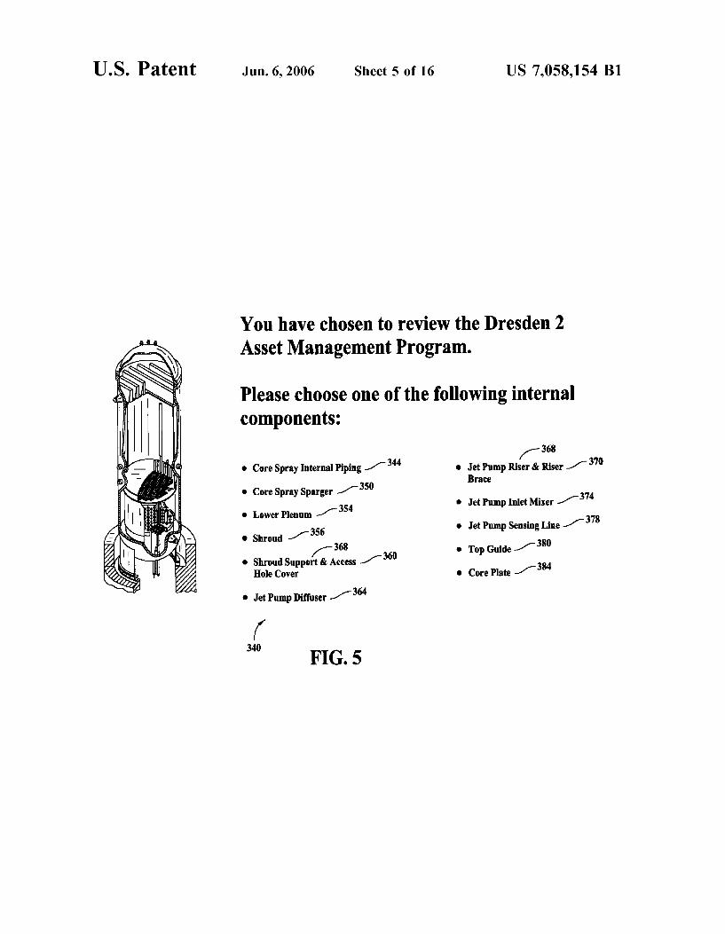
FIG. 5 is an exemplary embodiment of a user interface displaying various internal components of a speci?c plant (Dresden 2 Plant);
FIG. 6 is an exemplary embodiment of a user interface displaying various internal components of a speci?c plant (La Salle 1 Plant);
FIG. 7 is an exemplary embodiment of a user interface providing instructions to the user;
FIG. 8 is an exemplary embodiment of a user interface displaying con?guration draWings of a component entitled “Core Spray Internal Piping”;
FIG. 9 is an exemplary embodiment of a user interface displaying susceptibility of Welds relating to a component entitled “Core Spray Internal Piping”;
FIG. 10 is an exemplary embodiment of a user interface displaying Boiling Water Reactor (BWR) Fleet history infor mation of a component entitled “Core Spray Internal Pip 111g”;
FIG. 11 is an exemplary embodiment of a user interface displaying Inspection Tools information for a component entitled “Core Spray Internal Piping”;
FIG. 12 is an exemplary embodiment of a user interface displaying Baseline Inspection information for a component entitled “Core Spray Internal Piping”;

US 7,058,154 B1 3
FIG. 13 is an exemplary embodiment of a user interface displaying most up-to-date Inspection Experience informa tion for a component entitled “Core Spray Internal Piping”;
FIG. 14 is an exemplary embodiment of a user interface displaying most up-to-date Mitigation Methods information for a component entitled “Core Spray Internal Piping”;
FIG. 15 is an exemplary embodiment of a user interface displaying most up-to-date Repair Methods information for a component entitled “Core Spray Internal Piping”; and
FIG. 16 is an algorithm used by the system to help the user to practice the AMS When the user logs on to a home page of the Web site through the client system.
DETAILED DESCRIPTION OF THE INVENTION
Exemplary embodiments of systems and processes that facilitate integrated netWork-based electronic reporting and Work?oW process management related to the Asset Man agement System (AMS) are described beloW in detail. The systems and processes facilitate, for example, electronic submission of information using a client system, automated extraction of information, and Web-based assessment report ing for internal and external system users.
The AMS is capable of collecting, tracking and dissemi nating real time information about Boiling Water Reactor (BWR) internal components (also referred to as “Internals”), Pressurized Water Reactor (PWR) Internals, or Advanced Liquid Metal Reactor (AMLR) Internals. In an exemplary embodiment, a searchable netWork-based AMS collects, tracks and disseminates real time information regarding Boiling Water Reactor (BWR) internal components. Infor mation relating to each internal component of a speci?c plant is received by the system Which stores the information into a centraliZed database, updates the centraliZed database With information received, cross-references the information received against the speci?c plant, and provides information in response to an inquiry. The system provides solutions to cracked Internals and also plant speci?c analysis to indi vidual customers. The system alloWs access to the most recent information, Which Was previously not possible.
In the AMS, BWR Internals’ information is stored in the centraliZed database. The netWork based AMS provides convenient access to reactor Internals’ information, includ ing Internals’ susceptibility, knoWn ?eet issues, knoWn unit speci?c issues, up-to-date unit speci?c summary of inspec tions performed, inspection recommendations/ guidelines for the components of concern, and contingency options (repair or mitigation). The database is integrated into customer outage planning and markets solutions. Once into the plant’s home page, the user has an option to access information on any reactor internal that has been analyZed. The Internals include, but are not limited to, the folloWing: core spray piping, core spray sparger, loWer plenum, shroud, shroud support, jet pump, top guide, and core plate.
In an exemplary embodiment, for each reactor internal, the folloWing information can be accessed by a user:
BackgroundiThis section provides plant speci?c con ?guration draWings, as Well as materials and susceptibility information on given Welds.
Field HistoryiThis section provides up-to-date informa tion on ?eld cracking history.
InspectioniThis section provides information on inspec tion guidelines, plant speci?c inspection history, and the latest information on inspection techniques.
5
20
25
30
35
40
45
50
55
60
65
4 MitigationiThis section provides information on the
mitigation techniques that are applicable to the given com ponent being analyZed.
RepairiThis section provides information on the repair options that are applicable to the given component being analyZed. The AMS provides a formaliZed process to meet and
manage the Internals information pertaining to reactors and also helps achieve full compliance to government regulatory standards. The method utiliZes a Web application that ana lyZes either a single plant or multiple plants. For multiple plants, a summary sheet gives a quick overvieW of Where the plants stand With respect to NRC standards. The user has an option to link from the summary sheet to any plant, or can link directly from the home page to any plant. The systems and processes are not limited to the speci?c
embodiments described herein. In addition, components of each system and each process can be practiced independent and separate from other components and processes described herein. Each component and process also can be used in combination With other components and processes. The application is being implemented as the Training
Database utiliZing a Structured Query Language (SQL) With a client user interface front-end for administration and a Web interface for standard user input and reports. In an exem plary embodiment, the application is Web enabled and being run on a business entity’s intranet. In yet another embodi ment, the application is fully accessed by individuals having an authorized access outside the ?reWall of the business entity through the Internet. In a third exemplary embodi ment, the application is being run in a WindoWs NT envi ronment. The application is ?exible and designed to run in various different environments Without compromising any major functionality.
FIG. 1 is a simpli?ed block diagram of an Asset Man agement System (AMS) 10 including a server sub-system, also referred to as server system 12, and a plurality of client sub-systems, also referred to as client systems 14, connected to server system 12. In one embodiment, client systems 14 are computers including a Web broWser, such that server system 12 is accessible to client systems 14 via the Internet. Client systems 14 are interconnected to the Internet through many interfaces including a netWork, such as a local area netWork (LAN) or a Wide area netWork (WAN), dial-in connections, cable modems and special high-speed ISDN lines. Client systems 14 could be any device capable of interconnecting to the Internet including a Web-based phone or other Web-based connectable equipment. A database server 16 is connected to a centraliZed database 20 contain ing product-related information on a variety of products, as described beloW in greater detail. In one embodiment, centraliZed database 20 is stored on server system 12 and can be accessed by potential users at one of client systems 14 by logging onto server system 12 through one of client systems 14. In an alternative embodiment centraliZed database 20 is stored remotely from server system 12.
FIG. 2 is an expanded version block diagram of an exemplary embodiment of a server architecture of an Asset Management System (AMS) 22. Components in system 22, identical to components of system 10 (shoWn in FIG. 1), are identi?ed in FIG. 2 using the same reference numerals as used in FIG. 1. System 22 includes server system 12 and client systems 14. Server system 12 further includes data base server 16, an application server 24, a Web server 26, a fax server 28, a directory server 30, and a mail server 32. A disk storage unit 34 is coupled to database server 16 and directory server 30. Servers 16, 24, 26, 28, 30, and 32 are

US 7,058,154 B1 5
coupled in a local area network (LAN) 36. In addition, a system administrator’s Workstation 38, a user Workstation 40, and a supervisor’s Workstation 42 are coupled to LAN 36. Alternatively, Workstations 38, 40, and 42 are coupled to LAN 36 via an Internet link or are connected through an Intranet.
Each Workstation, 38, 40, and 42 is a personal computer having a Web broWser. Although the functions performed at the Workstations typically are illustrated as being performed at respective Workstations 38, 40, and 42, such functions can be performed at one of many personal computers coupled to LAN 36. Work stations 38, 40, and 42 are illustrated as being associated With separate functions only to facilitate an understanding of the different types of functions that can be performed by individuals having access to LAN 36.
In another embodiment, server system 12 is con?gured to be communicatively coupled to various individuals or employees 44 and to third parties, e.g., internal or external auditors, 46 via an ISP Internet connection 48. The com munication in the exemplary embodiment is illustrated as being performed via the Internet, hoWever, any other Wide area netWork (WAN) type communication can be utilized in other embodiments, i.e., the systems and processes are not limited to being practiced via the Internet. In addition, and rather than WAN 50, local area netWork 36 could be used in place of WAN 50.
In the exemplary embodiment, any authorized individual or an employee of the business entity having a Workstation 54 can access the Asset Management System (AMS). One of the client systems includes a senior manager’s Workstation 56 located at a remote location. Work stations 54 and 56 are personal computers having a Web browser. Also, Work stations 54 and 56 are con?gured to communicate With server system 12. Furthermore, fax server 28 communicates With employees located outside the business entity’s 44 and any of the remotely located client systems, including a client system 56 via a telephone link. Fax server 28 is con?gured to communicate With other client systems 38, 40, and 42 as Well.
FIG. 3 shoWs a con?guration of database 20 Within database server 16 of server system 12 shoWn in FIG. 1. Database 20 is coupled to several separate components Within server system 12, Which perform speci?c tasks.
Server system 12 includes a collection component 64 for collecting information from users into centralized database 20, a tracking component 66 for tracking information, a displaying component 68 to display information, a receiving component 70 to receive a speci?c query from client system 14, and an accessing component 72 to access centralized database 20. Receiving component 70 is programmed for receiving a speci?c query from one of a plurality of users. Server system 12 further includes a processing component 76 for searching and processing received queries against data storage device 34 containing a variety of information collected by collection component 64. An information ful ?llment component 78, located in server system 12, doWn loads the requested information to the plurality of users in the order in Which the requests Were received by receiving component 70. Information ful?llment component 78 doWn loads the information after the information is retrieved from data storage device 34 by a retrieving component 80. Retrieving component 80 retrieves, doWnloads and sends information to client system 14 based on a query received from client system 14 regarding various alternatives.
Retrieving component 80 further includes a display com ponent 84 con?gured to doWnload information to be dis played on a client system’s graphical user interface and a
20
25
30
35
40
45
50
55
60
65
6 printing component 88 con?gured to print information. Retrieving component 80 generates various reports requested by the user through client system 14 in a pre determined format. System 10 is ?exible to provide other alternative types of reports and is not constrained to the options set forth above.
Database 20 is divided into a Plant Information Section (PIS) 90, Internals Information Section (HS) 94 relating to each plant, and several sub-sections underlying each Inter nals. PIS 90 contains information about various plants including, but not limited to, BWR, PWR, and AMLR. Internals are the components that are used in building the entire system. Internals could vary from plant to plant. The Internals classi?ed in BWR could be different than Internals in PWR and Internals in AMLR. In one of an exemplary embodiment of the inventions, Internals classi?ed for BWR are: Core Spray Internal Piping, Core Spray Sparger, LoWer Plenum, Shroud, Shroud Support & Access Hole Cover, Jet Pump Di?cuser, Jet Pump Riser & Riser Brace, Jet Pump Inlet Mixer, Jet Pump Sensing Line, Top Guide, and Core Plate.
Several sub-sections underlying each Internals are: a Background Information Sub-Section (BISS) 96 Which accumulates data relating to con?guration draWings, suscep tibility, and so on, a Field History Information Sub-Section (FHISS) 98 involving data relating to each and every Boiling Water Reactors (BWR) installed in the ?eld, an Inspection Information Sub-Section (IISS) 104 identifying data on inspection tools, baseline inspection criteria and overall inspection experience summary pertaining to BWR’s, a Mitigation Information Sub-Section (MISS) 110 identifying mitigation methods and a Repair Information Sub-Section (RISS) 118 identifying repair methods. PIS 90, IIS 94, BIIS 96, FHISS 98, IISS 104, MISS 110 and RISS 118 Within database 20 are interconnected to update and retrieve the information as required.
System 10 accumulates a variety of personal and con? dential data for the business entity. Therefore, system 10 has different access levels to control and monitor the security of the system. Authorization for access is assigned by system administrators on a need to knoW basis. In an alternative
embodiment, system 10 provides access based on job func tions. In yet another embodiment of the invention, system 10 provides access based on positions and management author ity Within the business entity. The administration/editing capabilities Within system 10 are also restricted to ensure that only authorized individuals have access to modify or edit the information that is already existing in the system. These internal controls With reference to system security help system 10 to manage and control the access to the information. The architectures of system 10 as Well as various com
ponents of system 10 are exemplary only. Other architec tures are possible and can be utilized in connection With practicing the processes described beloW.
FIG. 4 is an exemplary embodiment of a user interface 300 of Asset Management System (AMS) 10 shoWn in FIG. 2. In one exemplary embodiment, user interface 300 dis plays di?ferent alternative plants to a user through various hypertext links. These linkages include a hypertext link to Dresden 2 plant 310, a hypertext link to Dresden 3 plant 312, a hypertext link to LaSalle 1 plant 316, a hypertext link to LaSalle 2 plant 320, a hypertext link to Quad Cities 1 plant 324, and a hypertext link to Quad Cities 2 plant 328. Each of the plants is managed by a different utility company. User interface 300, also knoWn as an Asset Management Sys tem’s home page, is linked to database 20. Database 20 is


