systems assurance guide - oracle
TRANSCRIPT

StorageTek SL500Systems Assurance Guide
E21060-07
April 2013

StorageTek SL500 Systems Assurance Guide
E21060-07
Copyright © 2004, 2013, Oracle and/or its affiliates. All rights reserved.
This software and related documentation are provided under a license agreement containing restrictions on use and disclosure and are protected by intellectual property laws. Except as expressly permitted in your license agreement or allowed by law, you may not use, copy, reproduce, translate, broadcast, modify, license, transmit, distribute, exhibit, perform, publish, or display any part, in any form, or by any means. Reverse engineering, disassembly, or decompilation of this software, unless required by law for interoperability, is prohibited.
The information contained herein is subject to change without notice and is not warranted to be error-free. If you find any errors, please report them to us in writing.
If this is software or related documentation that is delivered to the U.S. Government or anyone licensing it on behalf of the U.S. Government, the following notice is applicable:
U.S. GOVERNMENT END USERS: Oracle programs, including any operating system, integrated software, any programs installed on the hardware, and/or documentation, delivered to U.S. Government end users are "commercial computer software" pursuant to the applicable Federal Acquisition Regulation and agency-specific supplemental regulations. As such, use, duplication, disclosure, modification, and adaptation of the programs, including any operating system, integrated software, any programs installed on the hardware, and/or documentation, shall be subject to license terms and license restrictions applicable to the programs. No other rights are granted to the U.S. Government.
This software or hardware is developed for general use in a variety of information management applications. It is not developed or intended for use in any inherently dangerous applications, including applications that may create a risk of personal injury. If you use this software or hardware in dangerous applications, then you shall be responsible to take all appropriate fail-safe, backup, redundancy, and other measures to ensure its safe use. Oracle Corporation and its affiliates disclaim any liability for any damages caused by use of this software or hardware in dangerous applications.
Oracle and Java are registered trademarks of Oracle and/or its affiliates. Other names may be trademarks of their respective owners.
Intel and Intel Xeon are trademarks or registered trademarks of Intel Corporation. All SPARC trademarks are used under license and are trademarks or registered trademarks of SPARC International, Inc. AMD, Opteron, the AMD logo, and the AMD Opteron logo are trademarks or registered trademarks of Advanced Micro Devices. UNIX is a registered trademark of The Open Group.
This software or hardware and documentation may provide access to or information on content, products, and services from third parties. Oracle Corporation and its affiliates are not responsible for and expressly disclaim all warranties of any kind with respect to third-party content, products, and services. Oracle Corporation and its affiliates will not be responsible for any loss, costs, or damages incurred due to your access to or use of third-party content, products, or services.

iii
Contents
Summary of Changes ................................................................................................................................. ix
Preface ................................................................................................................................................................. xi
Documentation Accessibility ..................................................................................................................... xiObtaining Additional Documentation .................................................................................................... xi
1 Introduction
Library Features ........................................................................................................................................ 1-1Library Overview ..................................................................................................................................... 1-1Tape Drive and Media Compatibility .................................................................................................. 1-4
2 Capacity
Capacity on Demand .............................................................................................................................. 2-1Features and Restrictions ................................................................................................................. 2-1Host Notification for Capacity Changes ........................................................................................ 2-2
LTO-only Capacity .................................................................................................................................. 2-3Capacity Values - LTO Only ............................................................................................................ 2-3Physical Slot Configurations - LTO Only ...................................................................................... 2-4
Mixed Media Capacity ........................................................................................................................... 2-8Capacity Values - Mixed Media ...................................................................................................... 2-9Physical Slot Configurations - Mixed Media ............................................................................. 2-10
3 Partitioning
Partitioning Considerations ................................................................................................................... 3-1Partitioning Examples ............................................................................................................................ 3-2Access Control .......................................................................................................................................... 3-3Location Numbering ............................................................................................................................... 3-4CAP Behavior ........................................................................................................................................... 3-4
Split Assigned CAPs ......................................................................................................................... 3-4Common (Unassigned) CAPs ......................................................................................................... 3-5Mixed CAPs ....................................................................................................................................... 3-6The CAP Button ................................................................................................................................. 3-7

iv
4 Features and Hardware
Power System ........................................................................................................................................... 4-1Robotics Unit ............................................................................................................................................ 4-1Electronics ................................................................................................................................................. 4-2Operator Panels ....................................................................................................................................... 4-3
Keypad ................................................................................................................................................ 4-3Library Console ................................................................................................................................. 4-4Local Operator Panel ........................................................................................................................ 4-4
Cartridge Access Port .............................................................................................................................. 4-5Tape Drives and Cartridges ................................................................................................................... 4-5Safety Features ......................................................................................................................................... 4-5
Front Door and Robotics .................................................................................................................. 4-6Cards and Power Supply ................................................................................................................. 4-6Cooling Fans ...................................................................................................................................... 4-6
Library Interfaces .................................................................................................................................... 4-6Ethernet ............................................................................................................................................... 4-7Simple Network Management Protocol (SNMP) ......................................................................... 4-7SCSI LVD ............................................................................................................................................ 4-8Fibre Channel (FC) ............................................................................................................................ 4-8Serial Attached SCSI (SAS) .............................................................................................................. 4-9Bridging ............................................................................................................................................ 4-10
Library Management Software .......................................................................................................... 4-11Automated Cartridge System Library Software ........................................................................ 4-11
Independent Hardware and Software Vendors ............................................................................. 4-12Specifications ........................................................................................................................................ 4-12Warranties .............................................................................................................................................. 4-14Regulatory Agencies ............................................................................................................................ 4-14
EN60950-1:2001 Statement ............................................................................................................ 4-14Electromagnetic .............................................................................................................................. 4-15Fiber-optic ....................................................................................................................................... 4-15Fiber-optic Laser Product Label ................................................................................................... 4-15
5 System Assurance
System Assurance Planning Meetings ................................................................................................. 5-1Engagement Methodology ..................................................................................................................... 5-1
Actions for Sales Personnel............................................................................................................... 5-2
6 Site Planning
Site Survey ................................................................................................................................................. 6-1Site Preparation ........................................................................................................................................ 6-1Library Dimensions ................................................................................................................................. 6-1AC Power Planning.................................................................................................................................. 6-3Rack Planning ........................................................................................................................................... 6-4Airborne Contaminants ......................................................................................................................... 6-4Preparing for the Installation................................................................................................................. 6-5
Personnel ............................................................................................................................................. 6-5

v
Waste Disposal ................................................................................................................................... 6-5Tools ..................................................................................................................................................... 6-5
Support ....................................................................................................................................................... 6-6Service Delivery Platform ................................................................................................................. 6-6Oracle Premier Support for Systems ............................................................................................... 6-6Contacting Support............................................................................................................................ 6-7
Data Center Services ............................................................................................................................... 6-7
7 Ordering
Hardware Activation Files ..................................................................................................................... 7-1Activation File .................................................................................................................................... 7-1
Downloading Upgrades from Oracle Software Delivery Cloud ................................................... 7-2Part Numbers - SL500 Modular Library System ............................................................................... 7-2
Library with Base Module ................................................................................................................ 7-2Upgrade (X-options)—All SL500 Libraries ................................................................................... 7-3Tape Drives ........................................................................................................................................ 7-4Power Cord Numbers and Receptacles ......................................................................................... 7-5Redundant Power Supply................................................................................................................. 7-6Rack ..................................................................................................................................................... 7-7Partitioning ......................................................................................................................................... 7-7Library Interface Changes ................................................................................................................ 7-8Local Operator Panel ........................................................................................................................ 7-8Magazines ........................................................................................................................................... 7-8Interface Cables ................................................................................................................................. 7-8Cartridges and Labels .................................................................................................................... 7-11
A Tape Drives and Cartridges
LTO Tape Drives and Cartridges ......................................................................................................... A-1Ordering Cartridges ................................................................................................................................ A-2
B Controlling Contaminants
Environmental Contaminants ............................................................................................................... B-1Required Air Quality Levels ................................................................................................................. B-1Contaminant Properties and Sources .................................................................................................. B-2
Operator Activity .............................................................................................................................. B-3Hardware Movement ....................................................................................................................... B-3Outside Air......................................................................................................................................... B-3Stored Items ....................................................................................................................................... B-3Outside Influences ............................................................................................................................ B-3Cleaning Activity .............................................................................................................................. B-3
Contaminant Effects ............................................................................................................................... B-4Physical Interference......................................................................................................................... B-4Corrosive Failure............................................................................................................................... B-4Shorts .................................................................................................................................................. B-4Thermal Failure ................................................................................................................................. B-4
Room Conditions..................................................................................................................................... B-4

vi
Exposure Points ....................................................................................................................................... B-6Filtration .................................................................................................................................................... B-6Positive Pressurization and Ventilation ............................................................................................. B-7Cleaning Procedures and Equipment.................................................................................................. B-8
Daily Tasks ......................................................................................................................................... B-8Weekly Tasks ..................................................................................................................................... B-8Quarterly Tasks ................................................................................................................................. B-9Biennial Tasks .................................................................................................................................... B-9
Activity and Processes .......................................................................................................................... B-10
Glossary
Index

vii
List of Figures
1–1 Front View of Library Components ......................................................................................... 1-21–2 Rear View of Library Components........................................................................................... 1-32–1 Base Module, LTO-only Library Slots ..................................................................................... 2-52–2 Firmware, LTO-only Library Slot Mapping ........................................................................... 2-62–3 SCSI Element Numbering Mapping—LTO-only Library .................................................... 2-72–4 LTO-only Library Slots for Back Wall of Cartridge Expansion Module ............................ 2-82–5 Base Module, Mixed-Media Library Slots ........................................................................... 2-112–6 Firmware, Mixed-Media Library Slot Mapping.................................................................. 2-122–7 SCSI Mixed-Media Library Element Numbering Mapping .............................................. 2-132–8 Mixed-Media Library Slots for Back Wall of Cartridge Expansion Module................... 2-143–1 Slot Configuration for Partitioning Examples ....................................................................... 3-34–1 Robotics Unit .............................................................................................................................. 4-24–2 RLC Card Connectors ................................................................................................................ 4-34–3 Keypad ......................................................................................................................................... 4-44–4 Library Interfaces ....................................................................................................................... 4-74–5 SCSI LVD Example .................................................................................................................... 4-84–6 Fibre Channel Example ............................................................................................................. 4-94–7 Bridged SL500 Example ......................................................................................................... 4-114–8 ACSLS Example ...................................................................................................................... 4-126–1 Library and Rack Dimensions (Isometric View) .................................................................... 6-26–2 Library and Rack Dimensions (Top View).............................................................................. 6-36–3 Rack Frames and Rack Unit Measuring Identification.......................................................... 6-47–1 Activation Files Example .......................................................................................................... 7-2

viii
List of Tables
2–1 LTO-only Capacity Rules.......................................................................................................... 2-32–2 LTO-only Capacity Example .................................................................................................... 2-42–3 Mixed Media Library Capacity Rules ..................................................................................... 2-92–4 Mixed Media Library Capacity Example ............................................................................... 2-94–1 Library Component Weights................................................................................................. 4-134–2 Environmental Specifications................................................................................................ 4-134–3 Library Power without Tape Drives .................................................................................... 4-134–4 Library Power with Two LTO Tape Drives ........................................................................ 4-134–5 Library Power with Four LTO Tape Drives........................................................................ 4-146–1 Gas Limit Recommendations ................................................................................................... 6-56–2 Installation Tools........................................................................................................................ 6-67–1 Base Modules.............................................................................................................................. 7-37–2 Initial Order Tape Drives.......................................................................................................... 7-37–3 LTO-Only - Library and Module Upgrades (X-options)...................................................... 7-37–4 Mixed Media - Library and Module Upgrades (X-options) ................................................ 7-37–5 Partitioning - Library and Module Upgrades (X-options)................................................... 7-47–6 Initial Order Tape Drives.......................................................................................................... 7-47–7 LTO Tape Drives ........................................................................................................................ 7-47–8 SL500 LTO Tape Drive Conversion Trays.............................................................................. 7-57–9 Dual Port Upgrade Kits............................................................................................................. 7-57–10 Country-specific Power Cords 100 to 127 VAC..................................................................... 7-57–11 Country-specific Power Cords 200 to 240 VAC..................................................................... 7-57–12 Non-country-specific Power Cords......................................................................................... 7-67–13 Redundant Power Supply ........................................................................................................ 7-77–14 Rack Cabinet Assembly ............................................................................................................ 7-77–15 Partitioning Options .................................................................................................................. 7-77–16 Library Interface Changes, SCSI and Fibre Channel ............................................................ 7-87–17 Local Operator Panel ................................................................................................................. 7-87–18 Cartridge Access Port Magazines............................................................................................ 7-87–19 Ethernet Cables........................................................................................................................... 7-97–20 LC to LC 50/125 Micron - Two Gigabit Fiber-Optic Cables................................................ 7-97–21 LC to SC 50/125 Micron - Two Gigabit Fiber-Optic Cables ................................................ 7-97–22 LC to ST 50/125 Micron- Two Gigabit Fiber-Optic Cables ................................................. 7-97–23 SCSI Universal Interface Cables............................................................................................ 7-107–24 SCSI Terminators .................................................................................................................... 7-107–25 SAS Cables ............................................................................................................................... 7-10A–1 Tape Drive Comparisons ......................................................................................................... A-1A–2 Tape Drive Media Comparisons............................................................................................. A-2

ix
Summary of Changes
Date Revision Description
August 2004 A Initial Release
January 2005 B See this revision for details.
February 2005 C See this revision for details.
March 2005 D See this revision for details.
May 2005 E See this revision for details.
August 2005 F See this revision for details.
November 2005 G See this revision for details.
February 2006 H See this revision for details.
June 2006 J See this revision for details.
August 2006 K See this revision for details.
October 2006 L See this revision for details.
May 2007 M See this revision for details.
July 2008 MA See this revision for details.
October 2008 MB See this revision for details.
May 2010 MC See this revision for details.
October 2010 MD See this revision for details.
July 2011 01 Using new Oracle template.
Assigned a new document part number: (E21060-01).
November 2011 02 See this revision for details.
March 2012 03 See this revision for details.
June 2012 04 Updates to support the SAS LTO5 tape drive.
Updates to include SAS interface cable part numbers.
November 2012 05 Reorganization of content.
Updates to support LTO6.
January 2013 06 Updates to support new document template.
April 2013 07 Updates to tape drive appendix.

x

xi
Preface
This Systems Assurance Guide is intended for account executives, system engineers, professional services personnel, service engineers, marketing and sales representatives, plus anyone interested in information about Oracle’s StorageTek SL500 Modular Library System.
The systems assurance process is the exchange of information between sales, service, and the customer to ensure that no aspects of the sale, order, or installation processes are overlooked.
Documentation AccessibilityFor information about Oracle's commitment to accessibility, visit the Oracle Accessibility Program website at http://www.oracle.com/pls/topic/lookup?ctx=acc&id=docacc.
Access to Oracle SupportOracle customers have access to electronic support through My Oracle Support. For information, visit http://www.oracle.com/pls/topic/lookup?ctx=acc&id=info or visit http://www.oracle.com/pls/topic/lookup?ctx=acc&id=trs if you are hearing impaired.
Obtaining Additional Documentation The following procedure describes how you can obtain Oracle customer documentation relating to library and tape drive products. Documentation is separated into “Libraries” that are created for each product type. To obtain documentation:
1. Point your Web browser to:
http://www.oracle.com/technetwork/documentation/tape-storage-curr-187744.html
2. Bookmark this location. The page lists available document libraries by product family.
3. To view and download documents, scroll down to the section that lists the documents for the type of product that interests you. Sections include Storage- and Library-Management Software, Tape Libraries, Tape Drives, Storage Encryption, Storage Virtualization, Archiving Systems, and Local Area Networking.
4. To view a list of documents contained within the table, click “View Library” in the “Link” column to the left of the “Product Description” column. Click any of the links on the library index to download the corresponding document.

xii
5. To download a compressed archive file that contains the entire suite of documents, click the “Download” link.
1
Introduction 1-1
1Introduction
Oracle’s StorageTek SL500 Modular Library System is a storage solution that offers flexibility, scalability, and high availability. The product uniquely addresses clear customer requirements for very high availability defined as near-zero:
■ Near-zero scheduled downtime through dynamic additions in capacity (slots) and throughput (tape drives)
■ Near-zero unscheduled downtime through improved reliability, redundant components, and hot-swappable components
The SL500 library is simple to manage and easy to monitor with remote (standard) and local (optional) operator panels. The SL500 library is cost competitive with base configurations and the scalability to grow as needed by the customer. The SL500 library has high reliability that results in lower service costs, providing the customer with a lower total cost of ownership.
Library FeaturesThe SL500 library provides customers with the flexibility to design a storage system solution that meets their specific needs. A few major library features include:
■ Modular Design
– Consists of three module types: base module, drive expansion module, and cartridge expansion module.
– Provides storage capacity from 24 to 575 cartridge slots and 1 to 18 tape drives.
■ Capacity on Demand
– Provides ability to expand non-disruptively in real time by activating previously installed physical capacity
– Allows customer to purchase hardware in advance, but only pay for currently needed capacity
■ Multiple Software and Connectivity Options
– Supports several library management software options
– Allows for multiple host connectivity and partitioning options
Library OverviewThe SL500 library, shown in the figures below, is a self-contained, fully automated, cartridge tape storage system that is scalable and mounts into a standard 483 mm (19 in.) rack or cabinet. The base module is also available as a desktop version.

Library Overview
1-2 StorageTek SL500 Systems Assurance Guide
For physical dimensions of the library, see "Library Dimensions" on page 6-1.
Figure 1–1 Front View of Library Components
1. Base module
2. Expansion module
3. Library door
4. Expansion module cartridge access port
5. Library door lock
6. Base unit cartridge access port (CAP)
7. Keypad
8. Robotics unit (with removable facade)

Library Overview
Introduction 1-3
Figure 1–2 Rear View of Library Components
1. Base module
2. Drive expansion module
3. Cartridge expansion module
4. Redundant power supply
5. Standard power supply
6. Power supply cord receptacle
7. RLC controller card
8. MPU2 (Fibre Channel) or MPW/RLW (SCSI) PUA2 (Dual Port Fibre Channel)
9. Library main power switch
10. Library fans
11. Tape drive 1 in base unit
12. Tape drive 1 in expansion module
The base module contains the robotics unit and the base unit:
■ The robotics unit has the robotic components and the keypad.

Tape Drive and Media Compatibility
1-4 StorageTek SL500 Systems Assurance Guide
■ The base unit has up to 50 cartridge slots, one or two tape drives, and a 5-slot cartridge access port (CAP).
Expansion modules can be added below the base module:
■ Cartridge expansion modules (CEMs) provide additional cartridge storage.
■ Drive expansion modules (DEMs) increase the number of drives in the library and provide additional cartridge storage.
The Capacity on Demand feature allows the customer to add capacity as storage requirements increase, see Chapter 2, "Capacity" for more information. Additionally, the SL500 has partitioning capabilities, see Chapter 3, "Partitioning" for more information.
For details about the library hardware and other features, see Chapter 4, "Features and Hardware". For SL500 ordering information and part numbers, see Chapter 7, "Ordering".
Tape Drive and Media CompatibilityThe following drives and media are compatible with the SL500 library:
■ Linear Tape-Open (LTO) Ultrium tape drives:
– Hewlett-Packard LTO Generation 2, 3, 4, 5, and 6
– IBM LTO Generation 2, 3, 4, and 5
■ Quantum Super Digital Linear Tape (SDLT) tape drives:
– SDLT 320
– SDLT 600
– DLT-S4

2
Capacity 2-1
2Capacity
The SL500 library is a modular system that allows the customer to select the required capacity. This chapter outlines the key capacity options of the library.
Capacity on Demand The SL500 library includes the Capacity on Demand feature, which separates physical capacity from activated capacity. Capacity on Demand allows a client to incrementally pay for and activate desired capacity. As the client’s storage needs grow, the client can add modules and activate the necessary capacity.
To expand capacity within an already purchased module, the client only needs to purchase and install an activation file for the new capacity, and then restart the library.
Features and Restrictions Important features and restrictions of Capacity on Demand are:
■ Physical capacity versus Active capacity
– Only activated storage cells can be used for tape cartridge storage. Inactivated cells cannot be used for cartridge storage, nor can they be accessed by any hosts.
■ LTO-only capacity versus Mixed-media capacity
– Do not mix LTO and mixed-media arrays and magazines within the same library.
– The minimum capacity is 30 storage cells for LTO-only libraries, and 24 storage cells for mixed-media libraries.
– The capacity activation increments differ between the two drive types (see below).
■ Capacity activation is incremental
Note: Starting with SL500 firmware version 1300 and SLConsole version FRS_4.00, storage capacity upgrades must be installed through the SL500 activation utility. This feature controls cartridge storage cells only. All installed tape drives are available by default. All cells in CAPs configured for enter and eject operations are available if the module containing the CAP has any activated storage cells.

Capacity on Demand
2-2 StorageTek SL500 Systems Assurance Guide
– Full Base - For LTO only, the full base capacity is Base 30-50, which enables the additional 20 slots in the Base Module. For mixed media, the full base capacity is Base 24-42, which enables 18 additional slots.
– FullCEM –Enables all storage cells in a cartridge expansion module (CEM).
– 1/3 DEM –Enables one-third of the storage cells in a DEM. For two-thirds of a DEM, you would install two 1/3 DEM files. For a full DEM, you would install three 1/3 DEMs
■ Hardware activation files are required
– These files activate capacity within the library. See "Hardware Activation Files" on page 7-1 for more details on how to download and install these files.
– The order that capacity activation files are installed is not significant (that is, it does not need to match the order of the modules in the SL500 frame).
– After installing additional capacity, you must restart the library. Once verified by the library controller, the additional storage cells are available for use.
■ Storage capacity is cumulative
– Total capacity is equal to the sum of the capacities specified in each activation file installed on the library.
■ All storage cells must be contiguous
– Gaps in activated capacity are unsupported.
– You can begin adding capacity to a module only if the module directly above it is at full capacity. A FullBase capacity base unit is required, either from the initial order or with the upgrade conversion bill, before an expansion module can be added.
– Deleting a Capacity file for a module in the middle of a library causes the modules below it to be unavailable. Any partitioning definitions affected will need to be re-done to account for the deleted slots.
■ Capacity of the last module versus capacity with a module below
– The robot cannot access the bottom of the last module due to space constraints. However, when a new module is added below, the bottom of the module becomes accessible. A module type with any module below will have more capacity than when it is placed as the last module. (For clarification refer to "Capacity Values - LTO Only" on page 2-3 and "Capacity Values - Mixed Media" on page 2-9.)
Host Notification for Capacity Changes When active storage capacity changes, the library controller notifies all affected hosts according to their interface requirements. SCSI hosts are notified by a “Mode Parameters Changed” unit attention. The host must re-audit the library to discover the configuration changes. Customers must consult the appropriate tape management software documentation for detailed procedures and commands.
Note: CEMs should be placed at the bottom of any SL500 configuration.

LTO-only Capacity
Capacity 2-3
LTO-only Capacity
Customers can purchase additional capacity in the following increments:
■ Full Base - Referred to as Base 30-50, which enables the additional 20 slots in the Base Module.
■ FullCEM –Enables all storage cells in a cartridge expansion module (CEM).
■ 1/3 DEM –Enables one-third of the storage cells in a DEM. If the DEM is the last module, the first two 1/3 files add 26 slots each and the third adds 25 slots. If there is a module below, increments are 28, 28, and 28.
Purchasing and activating LTO slot capacity is covered in Chapter 7, "Ordering".
Capacity Values - LTO Only Table 2–1 and Table 2–2 assume:
■ There are no reserved cells.
■ The CAP is set to I/O.
■ If DEMs and CEMs are installed in the same library, the DEMs are above all of the CEMs (this is the preferred configuration).
Caution: Firmware problems: Do not mix LTO and mixed-media arrays and magazines within the same library. If expansion modules are added, the new modules must have the same type arrays as the existing modules.
Note: Do not install an EZ DEM below an original CEM. This is not physically allowed.
Table 2–1 LTO-only Capacity Rules
Description Physical Capacity Active Capacity Value Installed
Base Module only (shipped standard) 30 LimitedBase
as last module 50 FullBase (Base 30-50)
with any module below 66 FullBase (Base 30-50)
Adding a DEM as the last module 77 1/3 DEM (in increments of 26, 26, 25)
Adding a DEM with any module below 84 1/3 DEM (in increments of 28, 28, 28)
Adding a CEM after a DEM or Base as the last module
104 FullCEM
Adding a CEM after a DEM or Base with any module below
114 FullCEM
Adding a CEM after CEM as the last module 110 FullCEM
Adding a CEM after CEM with any module below
120 FullCEM

LTO-only Capacity
2-4 StorageTek SL500 Systems Assurance Guide
Capacity Example The following table depicts the capacity of a sample LTO-only library with a base module, a DEM, and a CEM.
Physical Slot Configurations - LTO Only Your software might conflict with the following numbering information. Refer to your software publication for unique information.
If the reserved slots are configured as storage slots, the numbering starts there. You may also configure the CAP slots as storage slots.
For firmware numbering four integers represent the cartridge and tape drive slots, as viewed from the front of the library.
The numbering scheme uses the 1) library, 2) module, 3) row and 4) column scheme.
1. Library number (always 0)
2. Library module number 1 (top of rack) through 5 (bottom of rack)
3. Row number 1 through 9 (base module) or 1 through 12 (expansion module)
4. Column number 1 through 9 for base module and drive expansion module, 1 through 11 for cartridge expansion module
Figure 2–1 shows an LTO-only library with only a base module.
Table 2–2 LTO-only Capacity Example
Module Capacity Value Installed Sequence Number
Additional Slots
Library Total Count
Base Module (as shipped standard)
LimitedBase -- 30 30
Base Module (full capacity) FullBase (Base 30-50) 100 +20 50
Drive Expansion Module Additional from Base Module above
-- +16 66
Drive Expansion Module (with first 1/3 DEM)
1/3 DEM (increments of 26, 26, 25)
101 +26 92
Drive Expansion Module (with second 1/3 DEM)
1/3 DEM (increments of 26, 26, 25)
102 +26 118
Drive Expansion Module (with third 1/3 DEM)
1/3 DEM (increments of 28, 28, 28)
103 +25 143
Cartridge Expansion Module Additional from DEM above +7 150
Cartridge Expansion Module (as last module)
FullCEM 104 104 254

LTO-only Capacity
Capacity 2-5
Figure 2–1 Base Module, LTO-only Library Slots
Figure 2–2 shows an LTO-only library with a base module that has nine reserved slots, one drive expansion module, and one cartridge expansion module.

LTO-only Capacity
2-6 StorageTek SL500 Systems Assurance Guide
Figure 2–2 Firmware, LTO-only Library Slot Mapping
Figure 2–3 shows a library with a base module that has two reserved slots, one drive expansion module, and one cartridge expansion module. The storage slot numbering begins with the first slot after the reserved slots in column 1. The figure shows two reserved slots, but there could be more. If the reserved slots are configured as storage slots, the top slot (row 1) would be 1.

LTO-only Capacity
Capacity 2-7
Figure 2–3 SCSI Element Numbering Mapping—LTO-only Library
Figure 2–4 shows the slot capacity of a cartridge expansion module according to which type of module is installed above and below it.

Mixed Media Capacity
2-8 StorageTek SL500 Systems Assurance Guide
Figure 2–4 LTO-only Library Slots for Back Wall of Cartridge Expansion Module
Mixed Media Capacity
Customers can purchase additional capacity in the following increments:
■ Full Base - Referred to as Base 24-42, which enables the additional 18 slots in the Base Module.
■ FullCEM –Enables all storage cells in a cartridge expansion module (CEM).
Caution: Firmware problems: Do not mix LTO and mixed-media arrays and magazines within the same library. If expansion modules are added, the new modules must have the same type arrays as the existing modules.

Mixed Media Capacity
Capacity 2-9
■ 1/3 DEM –Enables one-third of the storage cells in a DEM. If the DEM is the last module, slot counts increment by 21. If there is a module below, the first 1/3 files add 24 slots and last two add 23 slots each.
Purchasing and activating mixed media slot capacity is covered in Chapter 7, "Ordering".
Capacity Values - Mixed Media Table 2–3 and Table 2–4 assume:
■ There are no reserved cells.
■ The CAP is set to I/O.
■ If DEMs and CEMs are installed in the same library, the DEMs are above all of the CEMs (this is the preferred configuration).
Capacity Example The following table depicts the capacity for a sample mixed-media library with a base module, three DEMs, and a CEM.
Note: Do not install an EZ DEM below an original CEM. This is not physically allowed.
Table 2–3 Mixed Media Library Capacity Rules
Description Physical Capacity Active Capacity Value Installed
Base Module only (shipped standard) 24 LimitedBase
as the last module 42 FullBase (Base 24-42)
with any module below 56 FullBase (Base 24-42)
Adding a DEM as the last module 63 1/3 DEM (in increments of 21, 21, 21)
Adding a DEM with any module below 70 1/3 DEM (in increments of 24, 23, 23)
Adding a CEM after a DEM or Base Module as the last module
84 FullCEM
Adding a CEM after a DEM or Base Module with any module below
94 FullCEM
Adding a CEM after a CEM as the last module
90 FullCEM
Adding a CEM after a CEM with any module below
100 FullCEM
Table 2–4 Mixed Media Library Capacity Example
Module Value Sequence Number
Additional Slots*
Library Total Count
Base Module (as shipped) Shipped standard -- 24 24
Base Module (full capacity) Base 24-42 100 +18 42
Drive Expansion Module Additional from Base Module above +14 56
Drive Expansion Module (with first 1/3 DEM)
1/3 DEM (increments of 21, 21, 21) 101 +21 77

Mixed Media Capacity
2-10 StorageTek SL500 Systems Assurance Guide
Physical Slot Configurations - Mixed Media The following figures show cartridge slot and tape drive locations for various configurations of the mixed-media SL500 library.
Figure 2–5 shows an mixed-media library with only a base module.
Drive Expansion Module (with second 1/3 DEM)
1/3 DEM (increments of 21, 21, 21) 102 +21 98
Drive Expansion Module (with third 1/3 DEM)
1/3 DEM (increments of 21, 21, 21) 103 +21 119
Drive Expansion Module Additional from DEM above +7 126
Drive Expansion Module (with first 1/3 DEM)
1/3 DEM (increments of 21, 21, 21) 104 +21 147
Drive Expansion Module (with second 1/3 DEM)
1/3 DEM (increments of 21, 21, 21) 105 +21 168
Drive Expansion Module (with third 1/3 DEM)
1/3 DEM (increments of 21, 21, 21) 106 +21 189
Drive Expansion Module Additional from DEM above +7 196
Drive Expansion Module (with first 1/3 DEM)
1/3 DEM (increments of 21, 21, 21) 107 +21 217
Drive Expansion Module (with second 1/3 DEM)
1/3 DEM (increments of 21, 21, 21) 108 +21 238
Drive Expansion Module (with third 1/3 DEM)
1/3 DEM (increments of 21, 21, 21) 109 +21 259
Cartridge Expansion Module Additional from DEM above +7 266
Cartridge Expansion Module (as last module)
FullCEM 110 +84 350
Table 2–4 (Cont.) Mixed Media Library Capacity Example
Module Value Sequence Number
Additional Slots*
Library Total Count

Mixed Media Capacity
Capacity 2-11
Figure 2–5 Base Module, Mixed-Media Library Slots

Mixed Media Capacity
2-12 StorageTek SL500 Systems Assurance Guide
Figure 2–6 Firmware, Mixed-Media Library Slot Mapping

Mixed Media Capacity
Capacity 2-13
Figure 2–7 SCSI Mixed-Media Library Element Numbering Mapping

Mixed Media Capacity
2-14 StorageTek SL500 Systems Assurance Guide
Figure 2–8 Mixed-Media Library Slots for Back Wall of Cartridge Expansion Module

3
Partitioning 3-1
3Partitioning
The SL500 library supports up to eight partitions. Each partition can be accessed by one host or multiple hosts.
Partitioning is an optional feature. Activation is required to enable the feature. See "Hardware Activation Files" on page 7-1. If the customer orders the partitioning feature, the service representative must enable the feature and work with the systems administrators who will be involved with assigning the partitions.
Clear communication and cooperation among system programmers, network administrators and service representatives are essential. Be sure to share this information with all members involved in the partitioning effort and correspond with other members of the service community when assistance is required.
Partitioning ConsiderationsPartitioning has terms associated with it that you and your customer must understand to effectively use the feature. In certain cases, these terms redefine some concepts that are familiar with users of the traditional, non-partitioned library configuration.
“Partitioning” is defined as the process of dividing portions of a library into discrete sections. The partitioning feature offers great flexibility for users. A partition can be as small as a single storage slot, a single CAP slot, or one tape drive if desired. A library can also contain multiple partitions. Customers may set up partitions that are accessible by single or multiple hosts.
The key to understanding partitioning is knowing what partitions exist, their boundaries, and who has access to the specific partitions that are configured.
Setting up a partition requires some important considerations:
■ If one partition designates several tape drives solely to its partition, no other partitions can use these tape drives.
■ Partition users must also anticipate how much storage area is needed for their resident tape volumes and the amount of free slots required.
■ CAP assignments are also critical. CAP slots can be specifically assigned to certain partitions or left open for common use. This will be discussed in detail later.
Storage slots and drives that are not assigned a partition within a partitioned library cannot be accessed. A customer could leave an area of slots unassigned, for example, in preparation for a planned future partition.
Note: Before partitioning a library, ensure that all members of the team clearly understand the fundamentals of the partitioning feature.

Partitioning Examples
3-2 StorageTek SL500 Systems Assurance Guide
The SCSI element numbering within partitioned libraries is continuous for each partition, even if slot locations for each partition are non-contiguous.
Partitioning Examples Figure 3–1 is used in all partitioning examples in this chapter. The examples split the library into two partitions. Refer to the specific example for how Partition 1 and Partition 2 are divided. The example library below consists of a base, DEM, and CEM.

Access Control
Partitioning 3-3
Figure 3–1 Slot Configuration for Partitioning Examples
Access Control Host definitions are assigned to specific partitions. Customers can assign multiple host definitions to a single partition. However, they cannot assign the same host definitions to multiple partitions. For example, Partition 1 could be set up for hosts 2, 3, and 4; Partition 2 could have hosts 1 and 5 for host definitions. They could not, however, assign host 1 or 5 to both Partitions 1 and 2.

Location Numbering
3-4 StorageTek SL500 Systems Assurance Guide
The host definition consists of:
■ Host ID (WWN)
■ Port number
■ Logical unit number (LUN)
Location Numbering Location numbering is composed of four digits: Library number, Module number, Row number, and Column number.
In a non-partitioned library configuration, the location number for the library always begins with the number “0.” For partitioned libraries, however, the library number will change to the partition number.
■ If Partition 1 was composed of the entire base module, locating a cartridge in module 1, row 8, column 1 in the base module would translate into the following: 1, 1, 8, 1.
■ If Partition 2 was composed of the entire drive expansion module, row 10, column 1 would translate into 2, 2, 10, 1.
Refer to Figure 3–1. Consider a library with the following partitions: Partition 1 owns the base module and Partition 2 owns the drive expansion module and cartridge expansion module. For Partition 1, SCSI element numbering begins at the first available slot in the base module and continues through to the end of the base. For Partition 2, the first slot in the drive expansion module will begin the element numbering for that partition and continue through the cartridge expansion module.
CAP Behavior Configure CAPs (or CAP slots) for:
■ Assignment to a specific partition only (split assigned CAP)
■ Common use for those partitions that do not specifically assign slots (common CAP)
■ A combination of specific slots and common slots (mixed CAP)
Customers could conceivably partition two slots in an 8-slot CAP to a single partition and the remaining slots to a second partition, for example.
For partitioned libraries, these three configuration options for CAP assignments are explained below.
Split Assigned CAPs CAPs or CAP slots can be assigned to the sole use of a partition. When specific CAP slots are assigned to a specific partition, the split assigned CAP option is enabled
Careful planning for anticipated CAP usage is required when using this option. Only those CAP slots designated as split assigned can be used by the partition assigning them.
Split Assigned CAPs - Example The library (see Figure 3–1) is composed of a base, drive and cartridge expansion modules. In this example, all cartridge slots, drives and CAP slots in the base module comprise Partition 1. All cartridge slots, drives and CAP slots in the drive expansion

CAP Behavior
Partitioning 3-5
and cartridge expansion modules are assigned to Partition 2. Each partition has access to only the components configured for it.
If Partition 1 requests a CAP import operation, the procedure is:
■ The operator selects Partition 1’s CAP through either the local operator panel or SLConsole.
■ The CAP button on the base module is pressed.
■ The top CAP door is opened. All remaining CAP doors remain closed.
■ The operator completes the operation.
If Partition 2 requests a CAP import operation, the procedure is:
■ The operator selects Partition 2’s CAP through either the local operator panel or SLConsole.
■ The CAP button on the base module is pressed.
■ The top CAP door remains closed. All remaining CAP doors open.
■ The operator completes the operation.
Multiple split CAP assignments are available within a library. This is in contrast to common assigned CAPs (see below).
Common (Unassigned) CAPs The common (or unassigned) CAP configuration is present when there are no specified CAP slots designated (split assigned) to a partition or partitions. Strictly speaking, one does not “configure” or “assign” a CAP as common—any CAP slots that are not split assigned are available for mutual use among the remaining, unassigned partitions. Keep in mind that common CAPs are a unit, shared among those partitions that have no split assigned CAPs.
Common (Unassigned) CAPs - Example Referring to Figure 3–1, in this example, Partition 1 is set up to contain all cartridge slots and drives in the base module for a single host. The remaining cartridge slots and drives are a second partition used only by a second host. However, no CAP slots are explicitly assigned for a partition—both partitions can use all CAP slots.
An example of an import operation sequence for a common CAP is:
■ The operator selects the CAP through either the local operator panel or SLConsole.
■ An operator presses the CAP button.
■ All CAP doors open.
■ A cartridge is placed in any CAP slot.
■ The CAP door is closed.
■ The cartridge is placed into a slot within the requesting host’s partition.
Note: As the default behavior, if no partition has selected a CAP through the operator panel or Library Console, the library will behave as if all split configured CAPs have been assigned to the CAP button. If no common configured CAP slot containing a cartridge is exposed, all CAP doors that are designated as split assigned will open to expose all split configured CAP slots when the button is pressed.

CAP Behavior
3-6 StorageTek SL500 Systems Assurance Guide
In a second instance, assume that Partition 2 requests a CAP export operation of a cartridge. Since it is a common CAP, the operation is:
■ The operator selects the CAP through either the local operator panel or SLConsole.
■ The VOLSER of the cartridge to be exported is entered.
■ The cartridge is placed in any CAP slot.
■ All CAP doors open.
■ The operator completes the operation.
For common CAPs, slots may be used by all partitions who do not specifically assign them. However, only one partition can select a CAP for operation simultaneously. The operation must be completed before the CAP is released to someone else through either the operator panel or SLConsole.
Mixed CAPs A mixed CAP option is present when both split CAP and common CAP configurations are present within a library.
Mixed CAPs - Example Referring again to Figure 3–1, in this example, Partition 1 contains only the cartridge in module 1, column 5, row 1, and drive number 1 and the single CAP slot 1 in the base module. The remaining storage slots and drives are divided among partitions 2, 3, and 4. The remaining CAP slots are left unassigned. These unassigned CAP slots are usable by partitions 2, 3, and 4, but CAP slot 1 in the base module can only be used by Partition 1.
If Partition 1 requests a CAP export operation, the procedure is:
■ The operator selects its CAP through either the local operator panel or SLConsole.
■ The VOLSER of the cartridge to be exported is entered.
■ The cartridge is placed into the top CAP slot of module 1’s CAP.
■ The top CAP door is opened. All remaining CAP doors remain closed.
■ The operator completes the operation.
If Partitions 2 through 4 request an export operation, the procedure is:
■ The operator selects a CAP through either the local operator panel or SLConsole. For this example, assume that Partition 2 has selected the top CAP for placement of the cartridge.
■ The VOLSER of the cartridge to be exported is entered.
■ The cartridge is placed into any module 1 CAP slot except the top one.
■ All CAP doors open.
■ The operator closes all CAP doors.
■ Within mixed assigned CAP environments:
■ For common CAPs, one or more partitions can share those CAP slots not designated as split assigned.
■ For split assigned CAPs, several configurations are possible. For example, the 4-slot CAP in a base module could be split assigned to Partition 1; the top four slots in the drive expansion module’s CAP could be split assigned to Partition 2; the

CAP Behavior
Partitioning 3-7
bottom four slots in the drive expansion module’s CAP could be split assigned to Partition 3, and so forth. To fulfill the mixed definition, however, there must also be common CAP slots available.
The CAP Button For a non-partitioned library, pressing the CAP button opens all CAPs that are configured as CAPs. In a partitioned library, each partition must first have its CAP selected, using the operator panel or Library Console. This will dedicate the CAP button to the use of those partitions that selected a CAP or CAPs for operation. After selection, pressing the CAP button will open only the CAP doors assigned to that partition.
If not selected by any partition, pressing the CAP button will open only those CAP slots that are split assigned (see the note under "Split Assigned CAPs - Example" on page 3-4).
An important thing to remember is that if multiple partitions are assigned to the same CAP slots (that is, common slots)—and that CAP is selected for use by one partition—the CAP import/export operation must be completed and the new partition assignment made, before another member of that partition can gain access for CAP operations.

CAP Behavior
3-8 StorageTek SL500 Systems Assurance Guide

4
Features and Hardware 4-1
4Features and Hardware
This chapter explains the hardware and features of the SL500 library.
Power System The SL500 library comes with two power options: standard and redundant.
■ The standard option has one 110–240 VAC, single phase, 50–60 Hz power supply that provides DC power to the library.
■ The redundant option provides an additional power supply as an optional feature. To provide redundancy, each supply should be plugged into a separate branch circuit.
If something within the power supply or power source fails, the second supply provides power to the entire library until the failed power supply can be replaced or the power source is re-established.
See Table 4–3, Table 4–4, and Table 4–5 for the power specifications. For ordering information, see "Power Cord Numbers and Receptacles" on page 7-5 and "Redundant Power Supply" on page 7-6.
Robotics Unit The robotics unit (Figure 4–1) moves cartridges among the storage cells, tape drives, and cartridge access ports (CAPs) and is included with the base module. The three main components of the robotic unit are the:
■ Z drive assembly—Uses a pulley system to vertically move the X table up and down.
■ X table assembly—Moves the hand horizontally across the library.
■ Hand assembly—Contains the wrist motor, gripper assembly, and bar-code scanner:
– The wrist motor rotates the hand left and right.
– The gripper assembly has fingers that grasp the sides of the cartridge.
– The bar-code scanner targets and reads the volume serial numbers

Electronics
4-2 StorageTek SL500 Systems Assurance Guide
Figure 4–1 Robotics Unit
1. Z drive assembly
2. Hand assembly
3. Keypad (included because of its location)
4. X table assembly
Electronics The electronics for the library consists of two types of cards:
■ RLC (control) card—Contains the processor and controls the various functions of the library, such as the robotics, sensors, vision system, and the CAP. The RLC card also stores the library configuration and volume serial numbers of the cartridge tapes and their locations.
■ Interface card —Provides the type of interface attachment to the library:
– MPW/RLW card for a SCSI LVD interface
– MPU2 card for a Fibre Channel interface
– PUA2 card for a Dual Port Fibre Channel interface

Operator Panels
Features and Hardware 4-3
Figure 4–2 RLC Card Connectors
1. Private Ethernet port is for future use.
2. Not used.
3. Public Ethernet port is for remote service access, SLConsole, and SNMP.
4. Fault LED indicates that the control card has detected an error.
5. Reserved for future use.
6. Not used.
7. CLI port is an RJ-45 serial port for service representatives.
8. Active LED indicates the library controller is active.
Operator Panels There are three ways an operator can access the library:
■ Keypad (standard)
■ Remote operator panel using the Library Console (standard)
■ Local operator panel, touch screen (optional feature) - for ordering information, see "Local Operator Panel" on page 7-8
Keypad Figure 4–3 shows the keypad, which has two buttons and five LEDs.
■ The two buttons are:
– Door: calls the robot to move to the parked zone.
– CAP: opens the cartridge access port.
■ The five LEDs indicate library activity, service and fault status, CAP and front door status

Operator Panels
4-4 StorageTek SL500 Systems Assurance Guide
Figure 4–3 Keypad
1. Open Door button
2. Open Door indicator
3. Open CAP button
4. Open CAP indicator
5. Service Required indicator
6. Library Active indicator
7. Service Robot indicator
Library Console The SL500 library uses the StorageTek Library Console (SLConsole), a Java1application that provides a graphical user interface (GUI) for the library. This application is accessed from a remote PC (standard feature) that uses a TCP/IP connection to the library.
The SLConsole can help diagnose problems with the library and its attached devices (tape drives, CAPs, and robot). It allows you to:
■ Monitor device activity
■ Load firmware
■ Print reports
Local Operator Panel The local operator panel is an optional feature that can:
1 Java is a general purpose programming language with several features that make the language well suited for use on the internet and with Web browsers.

Safety Features
Features and Hardware 4-5
■ View library component details (status, properties, and statistics).
■ Locate a cartridge.
■ Move a cartridge.
■ Empty the hand.
■ Clean a tape drive.
Cartridge Access Port The cartridge access ports (CAPs) are located to the right of the front door of the library.
The base module has one standard CAP:
■ The library with LTO-only arrays has one 5-slot CAP.
■ The library with mixed-media arrays has one 4-slot CAP.
Each expansion module has a CAP consisting of two magazines:
■ The library with LTO-only arrays has two 5-slot magazines.
■ The library with mixed-media arrays has two 4-slot magazines.
For ordering information, see "Magazines" on page 7-8.
Tape Drives and Cartridges The following drives and media are compatible with the SL500 library:
■ Linear Tape-Open (LTO) Ultrium tape drives:
– Hewlett-Packard LTO Generation 2, 3, 4, 5, and 6
– IBM LTO Generation 2, 3, 4, and 5
■ Quantum Super Digital Linear Tape (SDLT) tape drives:
– SDLT 320
– SDLT 600
– DLT-S4
See Appendix A or the tape drive documentation for information about the tape drives that are compatible with the SL500 library. For ordering information, see "Tape Drives" on page 7-4 and "Cartridges and Labels" on page 7-11.
Safety Features The SL500 library has a combination of safety features throughout the library, which include:
■ Key to open and lock the front door
■ Robotics retracted and in a parked position
■ Protective modules for the logic cards
■ Cooling fans to prevent an overheating condition

Library Interfaces
4-6 StorageTek SL500 Systems Assurance Guide
Front Door and Robotics The robot is retracted into the park zone in the robotics unit when the front door is open. In addition, you must use a key to open the front door.
To open the front door:
1. Press the Door Open button on the keypad.
a. The software allows the current job to complete.
b. The software parks the robot by retracting it into the robotics unit.
2. When the Door Open indicator light turns on, use the key to open the door.
a. The front door must be opened with a key to ensure that the data is secure. If the door is not fully closed, a sensor relays the condition to the software for security and safety reasons.
b. Power is removed from the robot to prevent someone’s hand from being injured.
Cards and Power Supply The RLC card, interface card, and the power supply are housed inside protective modules to prevent you from coming into contact with hazardous voltages and sensitive electronics.
For ordering information, see "Power Cord Numbers and Receptacles" on page 7-5 and "Redundant Power Supply" on page 7-6.
Cooling Fans The library has two cooling fans that provide cooling for the library electronics.
The tape drives and power supplies have their own fans.
Library Interfaces The SL500 library uses the following interface connections:
■ Ethernet
■ SCSI LVD
■ Fibre Channel
■ Serial Attached SCSI (SAS)
For ordering information, see "Library Interface Changes" on page 7-8 and "Interface Cables" on page 7-8.

Library Interfaces
Features and Hardware 4-7
Figure 4–4 Library Interfaces
1. Ethernet connection
2. SCSI LVD card (MPW/RLW)
3. Fibre Channel card (MPU2/PUA)
Ethernet The SL500 library uses standard TCP/IP over Ethernet for the Library Console and Simple Network Management Protocol connections.
Simple Network Management Protocol (SNMP) Simple network management protocol (SNMP) is an application-layer protocol that performs network management operations over an Ethernet connection.
SNMP allows systems administrators to query the library for configuration, operation, and statistical information plus SNMP allows the library to alert systems administrators of potential problems.
Systems administrators and network managers can use SNMP to monitor and receive status from the library, such as:
■ Operational state of the library (firmware, serial number, online/offline)
■ Library elements (columns, panels, slots, CAPs)
■ Number of storage slots, media types, and tape drives
The SL500 library supports SNMPv3 and Management Information Base (MIB) II or higher.
Note: A private network connection to an Ethernet hub or switch is recommended for maximum throughput and minimum contention.

Library Interfaces
4-8 StorageTek SL500 Systems Assurance Guide
MIB is a viewable document that contains descriptions about the characteristics for a managed device. These characteristics are the functional elements for that device which can be monitored using SNMP software.
For SNMP information, refer to the SL500 Simple Network Management Protocol Guide.
SCSI LVD The small computer system interface (SCSI) is an ANSI standard, intelligent peripheral interface that has been in existence since the late 1970’s.
The low voltage differential (LVD) implementation is the most recent development of this interface and provides a low noise, low power, low amplitude signal. This lower signal allows for faster switching and higher data transmission speeds. However, this lower signal also reduces the length of cable allowed for an LVD bus. An LVD bus can be up to 12 m (40 ft) long and can support up to 16 devices.
The SL500 library implements the SCSI-3 standard that uses a 16-bit bus, and supports data rates of up to 80 MB/s. SCSI 3 is also know as Ultra3 SCSI, Fast SCSI (Fast-80), or Ultra SCSI (Ultra160).
Figure 4–5 SCSI LVD Example
Fibre Channel (FC) The SL500 Fibre Channel physical interface provides a native connection scheme that supports open system environments. Topologies include:
■ Switched Fabric: A switched fabric provides dynamic interconnections between nodes and multiple, simultaneous Fibre Channel connections for the network. If

Library Interfaces
Features and Hardware 4-9
the library is connected to a Fibre Channel switch or fabric-capable host, the library configures itself as a switched fabric topology and can support up to 16 million ports logged into the fabric.
■ Arbitrated Loop: Arbitrated loops provide multiple connections for devices that share a single loop and allow only point-to-point connections between an initiator and target. An arbitrated loop can connect up to 126 ports.
Figure 4–6 Fibre Channel Example
Serial Attached SCSI (SAS) For cable ordering information, see "Interface Cables" on page 7-8.
Serial Attached SCSI (SAS) is a computer bus that moves data to and from devices, for example, tape drives. The SAS interface is a point-to-point serial protocol that uses the standard SCSI command set.
The T10 technical committee of the International Committee for Information Technology Standards (INCITS) develops and maintains the SAS protocol.
Overview
Note: The switched fabric topology is recommended for the library.
Note: While the library supports the arbitrated loop topology, switched fabric is preferred for new or future implementations.

Library Interfaces
4-10 StorageTek SL500 Systems Assurance Guide
■ Serial connection.
■ Multiple Initiator Support.
■ Gigabit per second data transfer rates.
■ Scalable for media rates, distance, media, and protocols.
■ A bridged base unit must be used.
■ An HP LTO5 tape drive is required as the bridging tape drive.
Components
A typical Serial Attached SCSI system consists of the following basic components:
1. Initiators: A device that originates requests for processing by a target.
2. Targets: A device (SL500 library tape drives) containing logical units and target ports that receives requests for processing and sends responses to an initiator.
3. Expanders: Devices that provide large storage environments the ability to connect multiple targets and initiators through a switched device for scalability and redundancy. SAS benefits include improved performance, simplified cabling with the mini SAS connectors (iPass), and lower power requirements.
BridgingFor bridged library ordering information, see "Library with Base Module" on page 7-2.
When supported LTO-5 tape drives are installed but dedicated storage-control interface cards are not, command and control information is sent with the data in a single control/data path. When an SL500 library does not detect an Oracle StorageTek MPU2 Fibre Channel or RLW parallel SCSI interface card at startup, the library adopts a bridged configuration by default.
Data and command/control signals travel directly to the Serial Attached SCSI (SAS) or Fibre Channel data interface on the LTO-5 tape drive. The Automation Device Interface (ADI) on a designated LTO-5 bridge drive handles all control communications for the library or library partition. The ADI passes command and control signals to the library controller.
If a bridge drive has not been previously selected, the library selects the first bridge-capable drive that it can find, starting from the top of the library. An unpartitioned bridged library must have one bridge drive. A partitioned bridged library must have a bridge drive for each partition.
Currently, the SL500 library bridging feature is supported on HP LTO-5 Serial Attached SCSI (SAS) and Fibre Channel tape drives.
Library Management Software
Features and Hardware 4-11
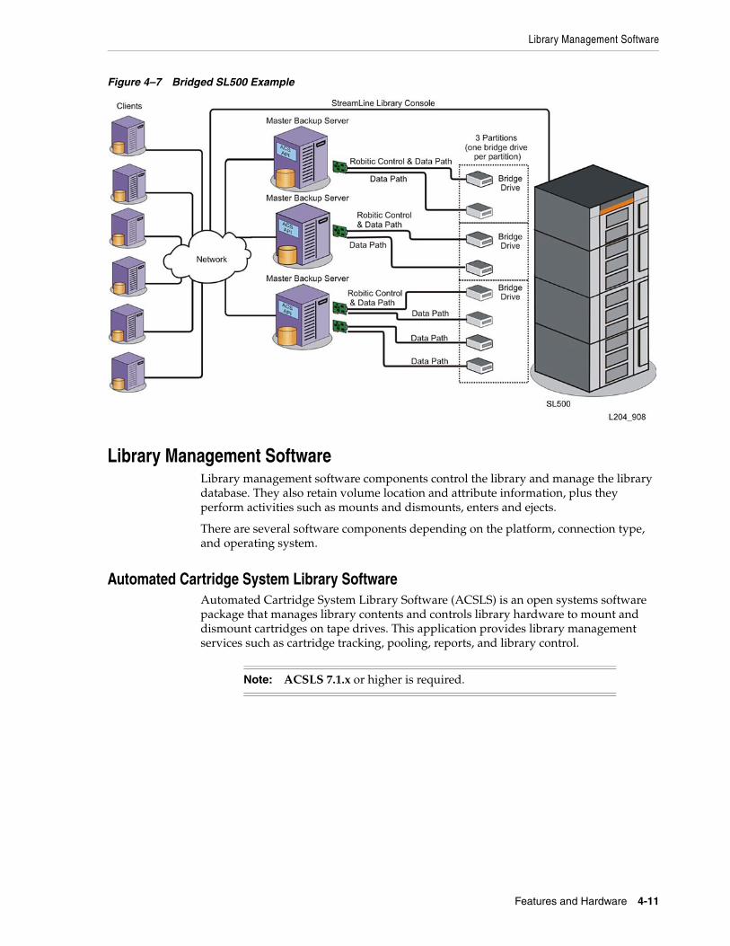
Figure 4–7 Bridged SL500 Example
Library Management Software Library management software components control the library and manage the library database. They also retain volume location and attribute information, plus they perform activities such as mounts and dismounts, enters and ejects.
There are several software components depending on the platform, connection type, and operating system.
Automated Cartridge System Library Software Automated Cartridge System Library Software (ACSLS) is an open systems software package that manages library contents and controls library hardware to mount and dismount cartridges on tape drives. This application provides library management services such as cartridge tracking, pooling, reports, and library control.
Note: ACSLS 7.1.x or higher is required.

Independent Hardware and Software Vendors
4-12 StorageTek SL500 Systems Assurance Guide
Figure 4–8 ACSLS Example
Independent Hardware and Software Vendors For the most current list of independent hardware and software vendors:
■ Go to http://tapeinterop.us.oracle.com
The Interop Tool is designed for connectivity information on products that are currently sold and supported by Oracle Corporation, regardless of whether such products are now Oracle or Sun branded or third party branded. The configurations listed are reflective of the most up-to-date information reported from various sources, including our testing labs and our technology partners. The Interop Tool lists configurations with valid connectivity, it does not validate the final configuration, the solution or if the configuration will perform in the end user's environment.
Specifications The following tables list the specifications for the rack, library and tape drives. See Figure 6–1 and Figure 6–2 for library and rack dimensions.
Note: In the following table, HP is a registered trademark of Hewlett-Packard Company. IBM is a registered trademark of International Business Machines. SDLT is a trademark of Quantum Corporation.

Specifications
Features and Hardware 4-13
Table 4–1 Library Component Weights
Component Weight
Base module with 1 power supply, 2 tape drives, and robotics unit 44.5 kg (98.0 lb)
Drive expansion module (DEM) with 1 power supply and 4 tape drives 41.3 kg (91.0 lb)
Cartridge expansion module (CEM) 20.1 kg (44.2 lb)
Robotics unit 10.1 kg (22.2 lb)
Power supply 2.3 kg (5.1 lb)
HP® LTO Ultrium tape drive and tray assy 3.6 kg (7.9 lb)
IBM® LTO Ultrium tape drive and tray assy 4.5 kg (9.9 lb)
SDLT™ LVD tape drive and tray assy 4.2 kg (9.3 lb)
SDLT FC tape drive and tray assy 4.1 kg (9.0 lb)
DLT-S4 tape drive and tray assembly 3.92 kg (8.65 lb)
Tape drive tray assy without tape drive 1.5 kg (3.4 lb)
LTO Ultrium cartridge 221 g (7.8 oz)
Table 4–2 Environmental Specifications
Specification Operating Storage Transporting
Temperature 10 to 40ºC (50 to 104ºF) 10 to 40ºC (50 to 104ºF) -40 to +60ºC (-40 to +140ºF)
Humidity 20 to 80% 10 to 95% 10 to 95%
Wet bulb (maximum, non-condensing)
+29.2ºC (+84.5ºF) +35ºC (+95ºF) +35ºC (+95ºF)
Altitude -76 to 3,048 m (-250 to 10,000 ft)
-- --
Table 4–3 Library Power without Tape Drives
Item Specification
Input voltage 100–240 VAC, single phase
Frequency 50/60 Hz
Maximum library power consumption 1.4 A @120 V or 0.8 A @240 V
Maximum heat output 614 Btu/hr
Voltage-amperes 180 VA
Table 4–4 Library Power with Two LTO Tape Drives
Item Specification
Input power 219 Watts
Input voltage-amperes 226 voltage-amperes
Input current (100 VAC) 2.3 amperes

Warranties
4-14 StorageTek SL500 Systems Assurance Guide
Warranties The initial warranty period for the SL500 is:
■ 5-by-9 next business day service level
■ Monday through Friday 8:00 a.m. to 5:00 p.m. Mountain time
■ 12 months from installation
Regulatory Agencies The following regulatory agencies have tested and certified the SL500 library.
■ Certified by Underwriters Laboratories Inc. (UL) to Standard for Information Technology Equipment -- Safety -- Part 1: General Requirements
■ UL 60950-1 First Edition
■ CAN/CSA-C22.2 No. 60950-1-03 First Edition
■ EN 60950-1 (IEC 60950-1:2001, modified)
■ CB Scheme in compliance to international Certified Body Scheme requirements with all national deviations
EN60950-1:2001 Statement The following statement pertains to products that require a ground connection at the wall outlet.
Norway: Apparatet må tilkoples jordet stikkontakt
Finland: Laite on liitettävä suojamaadoituskoskettimilla varustettuun pistorasiaan
Sweden: Apparaten skall anslutas till jordat uttag
Denmark: For tilslutning af de øvrige ledere, se medfølgende installationsvejledning.
Input current (120 VAC) 1.9 amperes
Input current (240 VAC) 0.9 amperes
Btu/hour 748 Btu/hr
Table 4–5 Library Power with Four LTO Tape Drives
Item Specification
Input power 288 Watts
Input voltage-amperes 297 voltage-amperes
Input current (100 VAC) 3.0 amperes
Input current (120 VAC) 2.5 amperes
Input current (240 VAC) 1.2 amperes
Btu/hour 983 Btu/hr
Table 4–4 (Cont.) Library Power with Two LTO Tape Drives
Item Specification

Regulatory Agencies
Features and Hardware 4-15
Electromagnetic Configuration used for verification and compliance in an SL500 Modular Library with a TCP/IP connection and 2 to 18 tape drives:
■ Federal Communications Commission (FCC) in compliance to the requirements of FCC 47, Part15, Subpart B and Unintentional Radiators Class A
■ Voluntary Control Council for Interference (VCCI) (Japan) in compliance to VCCI Class A (Cispr22)
■ Australia/New Zealand (C-Tick Mark) in compliance to requirements of the Australia/New Zealand EMC Framework AS/NZS 3548: 1995 Class A
■ European Community (CE Mark) in compliance to the requirements of Electromagnetic Compatibility Directive 89/336 (including all amendments).
■ Canadian Emissions (ICES) in compliance to the requirements of Canada's Interference Causing Equipment Standard ICES-003 Class A.
■ Taiwan (BSMI) in compliance to the requirements of Canada's Interference Causing Equipment Standard ICES-003 Class A.
■ Korea in compliance to the requirements of Korean EMC Law.
Fiber-optic Each fiber-optic interface in this equipment contains a laser transceiver that is a Class 1 Laser Product.
Each laser transceiver has an output of less than 70 µW.
These Class 1 Laser Products follow EN60825-1:1994+A1+A2 and with sections 21 CFR 1040.10 and 1040.11 of the Food and Drug Administration (FDA) regulations.
Fiber-optic Laser Product Label In accordance with safety regulations, a label on each StorageTek Fibre Channel product identifies the laser class of the product and the place and date of the manufacturer. The label appears on top of a Fibre Channel tape drive and near the Fibre Channel connectors on a Fibre Channel tape library.
A copy of the label is shown here:
CLASS 1 LASER PRODUCT LASER KLASSE 1 APPAREIL A LASER DE CLASSE 1 COMPLIES WITH 21 CFR 1040.10 AND 1040.11
The following laser safety and classification translations are for users in Finland and Sweden:
CLASS 1 LASER LUOKAN 1 LASERLAITE KLASSE 1 LASER APPARAT
WARNING: Use of controls or adjustment or performance of procedures other than those specified herein might result in hazardous radiation exposure.

Regulatory Agencies
4-16 StorageTek SL500 Systems Assurance Guide

5
System Assurance 5-1
5System Assurance
The system assurance process is the exchange of information among team members to ensure that no aspects of the sale, order, installation and implementation for the SL500 Library are overlooked. This process promotes an error-free installation and contributes to the overall customer satisfaction.
The system assurance team members make sure that all aspects of the process are planned carefully and performed efficiently. This process begins when the customer accepts the sales proposal. At this time, an Oracle representative schedules one or more system assurance planning meetings.
System Assurance Planning MeetingsThe purpose of the system assurance planning meetings are to:
■ Introduce the customer to Oracle’s StorageTek SL500 Library.
■ Explain the system assurance process and establish the team.
■ Identify and define the customer requirements.
■ Identify the configurations.
■ Complete the order.
■ Prepare for the installation and implementation.
Engagement Methodology Each individual engagement is different: different customers, different needs, and different requirements.
In addition to system assurance, Oracle has standardized and implemented a delivery methodology that provides continuity and quality assurance in the engagement and delivery approach. This suggested methodology is:
■ Assess
■ Design
■ Implement
■ Manage
This methodology consists of a defined path of action exchange of information. A series of templates and checklists found can be provided by sales to assist with this process. These templates and checklists document the necessary information to ensure

Engagement Methodology
5-2 StorageTek SL500 Systems Assurance Guide
that the proposed solution can be delivered and supported to achieve Oracle’s customer satisfaction requirements.
The methodology is designed for Oracle marketing, sales, and engagement personnel (such as Systems Engineers and Professional Services Engineers, plus qualified and approved partners). Following this methodology allows all members to work together, provide consistent documentation for each engagement and to ensure both customer satisfaction and overall sales success. The information in this document is intended to help insure that an SL500 library is successfully installed.
Actions for Sales Personnel■ Introduce the team members to the customer, exchange contact information.
■ Describe the SL500 modular library, options, and features for the customer.
■ Identify and define the customer’s requirements.
■ Understand the customer’s expectations.
■ Identify any additional items the customer might need:
– Library management software and additional hardware activation files, media—data and cleaning cartridges, labels, media services, tape drives, drive tray conversions, encryption, network components, and cables.
■ Ensure the site is ready to receive the SL500 library. Review the information in Chapter 6, "Site Planning".
■ Review and complete the site survey, found at:
http://my.oracle.com/site/pd/sss/products/tape/index.html
■ Place an order, see Chapter 7, "Ordering".
■ Install, and implement that solution by providing qualified service and support.

6
Site Planning 6-1
6Site Planning
This chapter provides planning information and requirements to consider before installation of an SL500 library. Key planning considerations include:
Site Survey■ System configuration: type of customer platform used
■ Applications: number and type of system backups, type of backup and archive software, type of library management software (such as ACSLS or ELS/HSC)
■ Hardware configuration: library capacity, tape drive type, media type
■ Network configuration: connectivity options, required network devices and cables
■ Content Management: partitioning plans, workloads and host contention issues
Site Preparation■ Physical space: floor space, placement
■ Power: source type, required amount
■ Environment: contaminants
■ Compatibility: tape drives, media, software
Library DimensionsThe following figures show the dimensions for the SL500 library.

Library Dimensions
6-2 StorageTek SL500 Systems Assurance Guide
Figure 6–1 Library and Rack Dimensions (Isometric View)
1. 48.3 cm (19.0 in.) width of front of base module with flange
2. 35.6 cm (14.0 in.) height of base module
3. 35.6 cm (14.0 in.) height of expansion module
4. 46.5 cm (18.3 in.) distance between rack holes
5. Original design modules (shown in figure): 60.9 cm (24.0 in.) to 86.4 cm (34.0 in.), optimally 74 cm (29 in.) front to rear rack mounting distance. EZ install modules: 55.9 cm (22.0 in.) to 78.7 cm (31.0 in.), optimally 66 cm (26 in.) front to rear rack mounting. Note: Extensions (optional accessory kit part 419930101) are available for rack depths up to 94 cm (37.0 in.).
6. 44.5 cm (17.5 in.) width of back of base module

AC Power Planning
Site Planning 6-3
Figure 6–2 Library and Rack Dimensions (Top View)
1. 60.9 cm (2 ft) minimum service clearance behind the library or rack
2. 81.0 cm (31.9 in.) depth of base module from front mounting plane to back of tape drives
3. 76.2 cm (30.0 in.)depth of original design base module, 71.4 cm (28.1 in.) depth of EZ install base module
4. 3.8 cm (1.5 in.) depth of front door, required clearance
5. 5.3 cm (2.1 in.) depth of front door and unique latch hardware
6. 5.9 cm (2.3 in.) key depth
7. 24.1 cm (9.5 in.) front door opening clearance
8. 60.9 cm (2 ft) minimum front service clearance
AC Power PlanningKeep in mind the following power considerations:
■ Plan the location for a second set of power wiring even if the customer is not purchasing the redundant power supply.
■ Ensure that each power source is on a separate branch circuit.

Rack Planning
6-4 StorageTek SL500 Systems Assurance Guide
■ If the rack has a power distribution unit (PDU), plug each power cable from the power supply receptacle to the PDU, and then plug the PDU cable to the wall receptacle.
■ If the rack does not have a PDU, plug each power cable from the power supply receptacle to the wall receptacle.
Rack PlanningThe SL500 library is a rack-mountable library that requires a standard 483-mm (19-in.) rack or cabinet for installation.
Most racks contain units of measure which are called RU’s (rack units). Each RU is equal to 44.5 mm (1.75 in.) and appear as a 3-hole pattern on the frame of the rack. For instance, some racks have numbers, notches, or markings to show where the top of the RU begins (see Figure 6–3 for an example).
The installation manual provides detailed instructions about where to install rack hardware and the adjustable brackets.
Figure 6–3 Rack Frames and Rack Unit Measuring Identification
1. Where the RU starts
2. The 3-hole RU pattern
Airborne Contaminants Control over contaminant levels in a computer room is an extremely important consideration when evaluating an environment. The impact of contamination on sensitive electronic hardware is well recognized, but the most harmful contaminants are often overlooked because they are so small.
Automated Tape Library components and electronics, tape drives, and media are subject to damage from airborne particulates. The operating environment must adhere to the requirements of: ISO 14644-1 Class 8 environment.
For more information refer to Chapter B, "Controlling Contaminants".
Gasses that are particularly dangerous to electronic components include chlorine compounds, ammonia and its derivatives, oxides of sulfur and petrol hydrocarbons. In the absence of appropriate hardware exposure limits, health exposure limits must be used.
Humidification with chlorinated water is a common source of damaging airborne chlorine. Appropriately designed carbon filters must be used to insure safe levels of airborne chlorine when chlorinated water is used for humidification.

Preparing for the Installation
Site Planning 6-5
The table below lists some recommendations for gaseous limits
PEL: Permissible Exposure Limit
ppm: Parts Per Million
µg/m3: Micrograms Per Cubic Meter
(c): ceiling
Preparing for the InstallationSite preparation is important to make sure that no aspects of the installation and implementation are overlooked and to promote an error-free installation. Considerations that you and the customer must make before the equipment arrives are outlined in the following sections.
PersonnelTo install an SL500 library, you need at least two qualified installers to lift some components from the boxes and to lift the base unit into the rack. A lifting tool is available for the original-design modules to hold the base unit in the rack so that one person can install the front and back screws.
Installation tips are supplied in the SL500 Installation Manual.
Waste DisposalOracle sales and service personnel should plan with customers for the disposal of all packing material. Determine if waste bins/recycling containers will be provided on site or whether an independent company will handle the disposal at additional cost.
ToolsThe table below lists the tools used to install the library, both standard tools found in most tool kits and special tools, with part numbers and quantity.
Table 6–1 Gas Limit Recommendations
Chemical Name Formula ASHRAE OSHA (PEL) ACGIH NIOSH
Acetic Acid CH3COOH Not defined 10 ppm Not defined Not defined
Ammonia NH 3500 µg/m3 350 ppm 25 ppm Not defined
Chlorine Cl 2100 µg/m3 31 ppm (c) Not defined 0.5 ppm (c)
Hydrogen Chloride HCl Not defined 5 ppm (c) Not defined Not defined
Hydrogen Sulfide H2S 50 µg/m3 320 ppm (c) 10 ppm 10 ppm
Ozone O3 235 µg/m3 30.1 ppm Not defined Not defined
Petrol-hydrocarbons Cn Hn Not defined 500 ppm 75 ppm 300 ppm
Sulfur Dioxide SO2 80 µg/m3 35 ppm 2 ppm 0.5 ppm (c)
Sulfuric Acid H2SO4 Not defined 1 ppm Not defined 1 ppm (c)

Support
6-6 StorageTek SL500 Systems Assurance Guide
SupportService and support representatives are available to assist with hardware and software problem resolution. During the initial order and installation planning, the customer should contact local and remote support with any questions.
Service Delivery PlatformThe Service Delivery Platform (SDP) is a support enhancement solution that provides faster problem resolution, analysis and trending, and improved diagnostic capabilities. The SDP consists of a smart appliance placed at the customer site that connects to the library and any StorageTek T-series tape drives. The SDP collects device events and alerts support analysts, providing remote diagnosis and auto service requests (ASR).
For more information, customers should contact an Oracle representative, or visit:
http://www.oracle.com/technetwork/systems/asr/documentation/oracle-installed-storage-330027.html
Oracle sales representatives should work with the customer to complete an SDP Systems Assurance Guide. Sales or service representatives can find the SDP Systems Assurance Guide and other SDP information at:
https://stbeehive.oracle.com/teamcollab/overview/Service+Delivery+Platform
Oracle Premier Support for SystemsOracle Premier Support is a fully integrated support solution for storage systems, such as the SL500 library. This support solution features:
■ Complete system coverage
■ Unlimited 24/7 access to Oracle system specialists
■ Essential product updates, such as firmware
■ Rapid-response hardware service
■ Premier gateway for personalized, proactive IT support
Table 6–2 Installation Tools
Tool Part Number Quantity
Standard Service Tool Bag
Tools include:
T10, T15, T20, and T25 Torx bits and driver,
Standard screwdrivers
Phillips screwdrivers
1/8 Allen wrench
24100250 1
Additional equipment
Step stool
Gloves
Flashlight
Obtain Locally As needed
Field Service Grounding Kit (ESD Kit) 4711 1
Optional SL500 install tool kit (temporarily installed in rack to support original design base unit)
314829201 As needed

Data Center Services
Site Planning 6-7
For more information visit: http://www.oracle.com/us/support/index.html
Contacting SupportThe Oracle Global Customer Support Contacts Directory can be found at: http://www.oracle.com/us/support/contact-068555.html
To purchase support:
■ United States Support Sales: +1.800.833.3536
If support has been purchased:
■ United States Technical Support: +1.800.223.1711
To submit, update, or review service requests go to My Oracle Support at: https://support.oracle.com/
Data Center Services Whether you need a new data center, a relocation, or an audit, Automated Cartridge System (ACS) has the resources to analyze, plan, and manage a project of any size.
In the information-gathering phase, ACS:
■ Gathers information about your customer's environment and requirements from audits, network maps, equipment inventories, and staff interviews.
■ Determines the scope of work and resources required.
■ Validates the requirements and formally state their findings in reports, executive summaries, and project plans.
■ Manages the project through completion once the scope, methods, and deliverables are agreed upon.
Data Center Services are available for customers, for both short- and long-term projects.
Offerings:
■ Hardware relocation and asset swaps
■ Asset management to identify assets of a data center and place them into a controllable state
■ Custom cabling, connectivity, conveyance, and design to provide cabling infrastructure to optimize performance, maintenance, and migration to emerging technologies
■ Media services to relocate tapes and racks or convert one form of media to another
■ Infrastructure services to design, remodel and optimize existing facilities.
■ Data center project management
For more information, contact your local Professional Services and Data Center Services representative.

Data Center Services
6-8 StorageTek SL500 Systems Assurance Guide

7
Ordering 7-1
7Ordering
This chapter describes the components and the ordering part numbers for the SL500 Modular Library System.
■ Some numbers are for ordering the initial library (referred to as ATO).
■ X-options (upgrades) are kits of material and instructions that allow for the addition of a feature or an upgrade to the library after the base module has been installed.
It is important to note that to add a module, the module above must be fully activated. For example:
■ To add a drive expansion or cartridge expansion module below a base module, the base module must have 50 (LTO-only) or 42 (mixed-media) active cartridge slots.
■ Slots must be contiguous. Slots within a lower module will not be recognized unless the upper module is fully activated.
Hardware Activation Files The Hardware Activation utility allows the customer (or a service representative) to install optional features on the library. Instructions for customers to install the hardware activation files are supplied in the SL500 User’s Guide. For SL500 hardware upgrade issues, customers should contact Technical Support and create a service request.
Two examples of hardware activations include:
■ Partitioning
■ Slot Capacity Upgrades
Activation File Activation files are available to the customer at Oracles Software Delivery Cloud located at: https://edelivery.oracle.com/. The site contains downloads for all licensable Oracle products.
The figure below shows an example of the Hardware Activation files that might be available to download by a customer.

Downloading Upgrades from Oracle Software Delivery Cloud
7-2 StorageTek SL500 Systems Assurance Guide
Figure 7–1 Activation Files Example
Once the file is downloaded, the customer (or service representative) can install the file through a session in the Library Console.
The file is a digitally signed image (.img) file containing one or more activation files for the features customers have purchased. Each activation file has a unique sequence number. The sequence number ensures that only one instance of an activation file can be installed on a library at a time.
SL500 hardware activation files are cumulative. When you install a new file, the included features are added to the features already installed on the library. These files do not expire.
Downloading Upgrades from Oracle Software Delivery Cloud For parts, such as slots, that require an activation file, the file can be downloaded from Oracles Software Delivery Cloud at: https://edelivery.oracle.com/
1. Choose a Language.
2. Enter your information.
3. Read and agree to legal/export terms and conditions.
4. Under select a product pack, choose Oracle StorageTek Products.
5. Under platform select “Generic Platform.”
6. Select the StorageTek SL500 Modular Library System.
7. Download the purchased features.
Part Numbers - SL500 Modular Library System The part numbers for SL500 library components are listed in this section.
Library with Base ModuleThe following table lists the part numbers for the library with a base module.

Part Numbers - SL500 Modular Library System
Ordering 7-3
Tape drives must be ordered separately from the library. The table below lists the part numbers for tape drives that can be ordered with the initial purchase of the SL500 library.
Upgrade (X-options)—All SL500 Libraries The table below lists the upgrade or X-options available.
LTO-only DEM activation: Up to three 1/3 files can be ordered. If this is the last module, the first two 1/3 files add 26 slots each and the third adds 25 slots. If there is a module below, increments are 28, 28, and 28.
Table 7–1 Base Modules
Description Part Number
LTO Only - SL500 base module, 30 slots, Fibre Channel (FC) interface SL500-30-FC-BASE
Bridged - SL500 base module, 30 slots, Fibre Channel (FC) Interface 7100273
Table 7–2 Initial Order Tape Drives
Description ATO Part Number
IBM LTO5 Fibre Channel (FC) interface LTO5-IBFC-D-SL500
HP LTO5 Fibre Channel (FC) interface LTO5-HPFC-D-SL500
HP LTO5 Six Gb SAS interface 7100278
Note: You must download the activation files for all part numbers in the table below before the feature can be used. See "Hardware Activation Files" on page 7-1 or the SL500 Users Guide for more details.
Table 7–3 LTO-Only - Library and Module Upgrades (X-options)
Upgrade Description X-option Part Number
SL500 30-50 slots (Full Base) Activates base module from 30 to 50 active slots (the CAP is not counted in slot capacity and is an additional 5 slots).
XSL500KBASE30-50-F
SL500 DEM w/ 1/3 slots DEM with first 1/3 slots access XSL500K-DEM-W1/3-F
SL500 1/3 DEM slots Upgrade for access to second 1/3, or third 1/3 DEM slots
XSL500K-DEMSLOTS-F
SL500 LTO CEM Cartridge expansion module (these modules do not contain drive bays).
XSL500K-LCARTEX-F
Table 7–4 Mixed Media - Library and Module Upgrades (X-options)
Upgrade Description X-option Part Number
Mixed Media 24-42 slots (Full Base)
Activates base module from 24 to 42 active slots (the CAP is not counted in slot capacity and is an additional 4 slots).
XSL500K-MM-24-42-F

Part Numbers - SL500 Modular Library System
7-4 StorageTek SL500 Systems Assurance Guide
Mixed-media DEM activation: Up to three 1/3 files can be ordered. If this is the last module, slot counts increment by 21 for each 1/3 file. If there is a module below, increments are 24, 23, 23.
Tape Drives The following tables list the part numbers for the LTO tape drives and conversion trays. The conversion trays allow the client to take a tape drive from another StorageTek library and place it in an SL500 tray.
Always, check the corporate website for the most current information on the availability of tape drives.
Mixed Media DEM 1/3 DEM with first 1/3 slots access XSL500K-MM-DEM-F
Mixed Media DEM Additional 1/3 slots
DEM upgrade for access to second 1/3 or third 1/3 DEM slots
XSL500K-MM-DSLOT-F
Mixed Media CEM Cartridge expansion module (these modules do not contain drive bays)
XSL500K-MM-CEM-F
Table 7–5 Partitioning - Library and Module Upgrades (X-options)
Upgrade Description X-option Part Number
SL500 Partitioning Physical partitioning feature, up to 8 partitions allowed.
X-SL500K-PARTNG-F
SL500 Partitioning for Legato Maintains the Legato boundary after installing any new library hardware.
XSL500K-LEG-PARTG-F
Note: All StorageTek LTO-5 tape drives ship with the drive hardware required to support Oracle Key Manager (OKM) encryption. StorageTek LTO4 drives can be selected to ship encryption ready. To use OKM encryption, customers must purchase the Encryption Activation product for each drive intended to work with OKM and upgrade the drive firmware to the latest release.
Table 7–6 Initial Order Tape Drives
Description ATO Part Number
IBM LTO5 Fibre Channel (FC) interface LTO5-IBFC-D-SL500
HP LTO5 Fibre Channel (FC) interface LTO5-HPFC-D-SL500
HP LTO5 Six Gb SAS interface 7100278
Table 7–7 LTO Tape Drives
Description Part Number
HP LTO6 Fibre Channel (FC) interface 7048546
HP LTO5 Fibre Channel (FC) interface LTO5-HP8FC-SL500Z
HP LTO5 SAS interface 7100968
IBM LTO5 Fibre Channel (FC) interface LTO5-IB8FC-SL500Z
Table 7–4 (Cont.) Mixed Media - Library and Module Upgrades (X-options)
Upgrade Description X-option Part Number

Part Numbers - SL500 Modular Library System
Ordering 7-5
The table below lists the part numbers for converting drives from another StorageTek library to the SL500 library.
Power Cord Numbers and Receptacles ■ Table 7–10 and Table 7–11 list power cord part numbers by country.
■ All cords are 3 meters (9.81 ft). The receptacle type is listed also.
■ Refer to the vendor catalog for the part number.
If your country is not listed below, use the cord that you used on past products.
Note: Order cables separately for tape drives.
Table 7–8 SL500 LTO Tape Drive Conversion Trays
Description Part Number
HP LTO5 FC SL3000/SL8500 7103007
IBM LTO5 FC SL3000/SL8500 7103004
HP LTO4 FC L180/L700/L1400/SL3000/SL8500 7103012
HP LTO4 SCSI L180/L700/L1400 7103011
IBM LTO4 FC L180/L700/L1400/SL3000/SL8500 LTO4-IBFC-SL5-CK-N
IBM LTO4 SCSI L180/L700/L1400 LTO4-IBSC-SL5-CK-N
HP LTO3 FC L180/L700/L1400/SL3000/SL8500 7103012
HP LTO3 SCSI L20/40/80/180/700 7103011
IBM LTO3 FC L180/L700 LTO3-IBFC-SL5-CK-N
IBM LTO3 SCSI L20/L40/L80/L180/L700 7103011
Table 7–9 Dual Port Upgrade Kits
Description Part Number
LTO5 (HP or IBM) 7102997
LTO4 (HP or IBM) XL5-SL500-DPCK
LTO3 and LTO2 (HP) XL2-3-HF-SL5DPCK-N
Table 7–10 Country-specific Power Cords 100 to 127 VAC
Country Part Number Receptacle Type
US/Canada PWRCORD10187019-Z 5-15R
Japan PWRCORD10083243-Z JIS C8303
Table 7–11 Country-specific Power Cords 200 to 240 VAC
Country Part Number Receptacle Type
Australia PWRCORD10083244-Z AS 3112
Denmark PWRCORD10083248-Z DEMKO107/ 10-1973
Europe PWRCORD10187018-Z Schuko

Part Numbers - SL500 Modular Library System
7-6 StorageTek SL500 Systems Assurance Guide
Notes:
1. Cabinets come equipped with two domestic or international power cords for the PDUs. However, you must order the correct number of power cables that run between each module’s power supply and the PDU. For example, if your US/Canada library contains a Base Module and one Drive Expansion Module, order two cables (PWRCORD10187055-Z); if this is a duplicate power configuration, you must order four cables.
2. This is a harmonic no plug cord for Belgium, Denmark, Finland, France, Germany, Holland, Norway, Sweden, and Switzerland.
Redundant Power SupplyThe following table lists the part number to order a redundant power supply for the base module or drive expansion module.
If something within the AC power source or supply fails, the second power supply provides power to the robotics and library electronics until the problem can be fixed. For redundancy, this power supply should be connected to a separate branch circuit. Make sure that you also order additional power cables, connected between the redundant supplies and the power distribution unit (PDU).
Europe (Continental)3 PWRCORD10187022-Z IEC309
Italy PWRCORD10083245-Z CEI 23-16/V11
Korea PWRCORD10083657-Z KSC 8305
South Africa PWRCORD10083636-Z BS546
Switzerland PWRCORD10083246-Z CEE 7
United Kingdom PWRCORD10083247-Z BS 1363
US/Canada PWRCORD10187020-Z 6-15R
Table 7–12 Non-country-specific Power Cords
Description Part Number
100 to 127 VAC - SJT IEC320 14AWG, 3 m, receptacle 5-15
PWRCORD10187061-Z
250 VAC - SJT 16 AWG L6-15P, C13, 2.5 m, receptacle L6-15P
PWRCORD10187024-Z
250 VAC - 18, 3, SVT, 1mm, M/SH FRT PWRCORD10187055-Z (for SL-RACK-42-Z rack)
250 VAC - 3, F, IEC320 harmonizedsee Note PWRCORD10187047-Z
100 to 240 VAC - International power cord pigtail PWRCORD10083735-Z
Note: These cords have a plug on one end that attaches to the library and bare wires on the other. Buy the correct end to match your normal wall outlet and attach it to the cord.
Table 7–11 (Cont.) Country-specific Power Cords 200 to 240 VAC
Country Part Number Receptacle Type

Part Numbers - SL500 Modular Library System
Ordering 7-7
Rack You can order a rack from Oracle or from another vendor. The following table lists the part numbers and feature codes.
Notes:
1. PDU specifications for both racks: Two 240 VAC PDUs, 20 A, IEC C13 receptacles, IEC C20 input with current meter, mounted at left rear of enclosure (viewed from the rear).
2. This rack offers added strength for installation of auxiliary equipment (disks, servers). The SL500 library and auxiliary equipment can be shipped installed within this cabinet.
For cabinets or racks with a depth beyond 80.0 cm (31.5 in.) but not exceeding 94 cm (37 in.), rear support extensions for EZ Install modules are available. For each module, you must contact Technical Support and order an optional accessory kit part 419930101, which contains the following:
■ 4 screws, part 10207301
■ Right extension, part 4198851xx
■ Left extension, part 4198853xx
Partitioning Partitioning requires a hardware activation file which can be downloaded from Oracles Software Delivery Cloud at: https://edelivery.oracle.com/. Refer to the SL500 User’s Guide for installation procedures.
Table 7–13 Redundant Power Supply
Description ATO Part Number PTO Part Number
Redundant power supply SL500-RPWR XSL500-RED-PWR-Z-N
Table 7–14 Rack Cabinet Assembly
Description Part Number
42 RU, 19-inch rack cabinet assembly (Model SL-RACK-42-Z)See Note 1 SL500K-RACK
42 RU, 19-inch rack cabinet assembly (X-Option) SL-RACK-42-Z-N
1000-38 rack with power distribution unitSee Notes 1 and 2 SRK-XRS038A-IP
Filler panel kit (12 RU), optional but recommended X6826A
Domestic power cord kit, 4 pack, order quantity 1 X6828A
Second power strip upgrade X-option XSL-RACK-2STRIP-Z
Table 7–15 Partitioning Options
Description Part Number
SL500 Partitioning X-SL500K-PARTNG-F
SL500 Partitioning for Legato XSL500K-LEG-PING-F

Part Numbers - SL500 Modular Library System
7-8 StorageTek SL500 Systems Assurance Guide
Library Interface Changes The following table lists the part numbers to change the library interface. (Available as X-Option only)
Local Operator Panel An optional local touch screen operator panel can be mounted on the front of the library. This is a panel-mounted personal computer with a flat screen display and touchable interface—no mouse or keyboard is needed. The panel can be installed on the door, either in the bottom section of the base module or the middle section of the top expansion module.
The following table lists the part number to order the local operator panel.
Magazines The following table lists the part numbers for the cartridge access port (CAP) magazines.
Interface Cables The following sections provide information about the different interface cables available. When you order cables, keep this in mind:
■ Riser cables can be used in computer rooms. Riser cable materials are not classified according to flammability or toxic gas emissions.
■ Plenum cables are designed for installation in air ducts and manufactured to meet UL standards for flammability to produce little smoke.
Ethernet CablesThe library uses Ethernet cables for TCP/IP connections. The following table lists the Ethernet cables available.
Table 7–16 Library Interface Changes, SCSI and Fibre Channel
Description Part Number
SCSI library interface to a Fibre Channel interface XSL500-SCSI-FC-Z-N
Table 7–17 Local Operator Panel
Description ATO Part Number PTO Part Number
Local operator panel SL500-OPPAN XSL500-TSOP-Z-N
Table 7–18 Cartridge Access Port Magazines
Description Part Number
Five-slot magazine for a CAP in an LTO-only library XSL500-LTO-MAG5-N
Four-slot magazine for a CAP in a mixed-media library XSL500-MM-MAG4-Z-N

Part Numbers - SL500 Modular Library System
Ordering 7-9
Two Gigabit Fiber-Optic CablesTwo gigabit (50-micron) fiber-optic cables are generally orange in color with LC connectors. LC connectors are the industry standard for all two gigabit Fibre Channel devices such as LTO tape drives. Both the library and tape drive interfaces use LC connectors. Do not use 62.5 micron cables.
The following table lists the part numbers for the two gigabit fibre-optic cables.
Table 7–19 Ethernet Cables
Description Part Number
Cable assembly, CAT5E, 127 cm (50 in.) 24 AWG, shielded CABLE10187035-Z
Cable assembly, CAT5E, 2.4 m (8 ft), 24 AWG, shielded CABLE10187033-Z
Cable assembly, CAT5E, 10.5 m (35 ft), 24 AWG, shielded CABLE10187034-Z
Table 7–20 LC to LC 50/125 Micron - Two Gigabit Fiber-Optic Cables
Description Part Number
10 m (32.8 ft) Duplex, Riser CABLE10800310-Z
50 m (164 ft) Duplex, Riser CABLE10800311-Z
100 m (328 ft) Duplex, Riser CABLE10800312-Z
10 m (32.8 ft) Duplex, Plenum CABLE10800313-Z
50 m (164 ft) Duplex, Plenum CABLE10800314-Z
100 m (328 ft) Duplex, Plenum CABLE10800315-Z
Table 7–21 LC to SC 50/125 Micron - Two Gigabit Fiber-Optic Cables
Description Part Number
10 m (32.8 ft) Duplex, Riser CABLE10800317-Z
50 m (164 ft) Duplex, Riser CABLE10800318-Z
100 m (328 ft) Duplex, Riser CABLE10800319-Z
10 m (32.8 ft) Duplex, Plenum CABLE10800320-Z
50 m (164 ft) Duplex, Plenum CABLE10800321-Z
100 m (328 ft) Duplex, Plenum CABLE10800322-Z
Adapter Kit, LC to SC Cabling CABLE315447901-Z
Table 7–22 LC to ST 50/125 Micron- Two Gigabit Fiber-Optic Cables
Description Part Number
10 m (32.8 ft) Duplex, Riser CABLE10800247-Z
50 m (164 ft) Duplex, Rise CABLE10800248-Z
10 m (32.8 ft) Duplex, Plenum CABLE10800323-Z
50 m (164 ft) Duplex, Plenum CABLE10800250-Z
Adapter Kit, LC to SC Cabling CABLE315447901-Z

Part Numbers - SL500 Modular Library System
7-10 StorageTek SL500 Systems Assurance Guide
SCSI Cables You may choose to separate the control path and the data paths when planning for a SCSI installation.
■ The control path transfers commands for library robotic operations.
■ The data path transfers data to and from the tape drives.
At least one initiator (a server) and one target (a tape drive) must be on a bus. Depending on the type of SCSI implementation, you may have up to 16 devices connected to the same SCSI bus.
Important: For the best performance, do not connect more than two tape drives on a single SCSI bus (called daisy-chaining).
The following table lists the part numbers for the SCSI universal interface cables.
SCSI TerminatorsThe following table lists the part numbers for the SCSI terminators.
SAS Interface Cables The SL500 library can use Serial Attached SCSI (SAS) tape drives and cables for interface connections. The following table lists the cables available.
Table 7–23 SCSI Universal Interface Cables
Description Part Number
SCSI, 68MD-68MD, 300 mm (11.8 in.) CABLE10187004-Z
SCSI, 68MD-68MD, 500 mm (19.7 in.) CABLE10187005-Z
SCSI, 68MD-68MD, 1 m (3.3 ft) CABLE10187006-Z
SCSI, 68MD-68MD, 3 m (9.8 ft) CABLE10187008-Z
SCSI, 68MD-68MD, 5 m (16.4 ft) CABLE10187009-Z
SCSI, 68MD-68MD, 10 m (32.8 ft) CABLE10187010-Z
SCSI, 68MD-68HD, 3 m (9.8 ft) CABLE10187011-Z
SCSI, 68MD-68VHD, 5 m (16.4 ft) CABLE10187012-Z
SCSI, 68MD-68VHD, 10 m (32.8 ft) CABLE10187013-Z
LVD daisy-chain cable 300 mm (11.8 in.) CABLE10083685-Z
Table 7–24 SCSI Terminators
Description Part Number
Pass-thru terminator for RLW/MPW card CABLE10148029-Z
Standard LVD/SE terminator for SCSI tape drive CABLE10148031-Z
Table 7–25 SAS Cables
Description ATO Part Number PTO Part Number
1x1 cable assembly, 4X mini SAS 3 meters shielded 7100276 7100277
2x1 cable assembly, 3 meters 7100274 7100245

Part Numbers - SL500 Modular Library System
Ordering 7-11
Cartridges and Labels Contact your authorized selling agent for approved labeled cartridges.
■ Call 1.877.STK.TAPE to order media from your local reseller or to obtain media pre-sales support.
■ E-mail [email protected]
See the tape media area on the corporate web site for additional information.
http://www.oracle.com/us/products/servers-storage/storage/tape-storage/overview/index.html
You must select the volume serial number (VOLSER) range and other label options when ordering cartridges. If you choose to order additional labels, order them from any standard media vendor.
Labels used in StorageTek libraries can be made by any vendor that produces a label that meets the Label Specification. Some vendors (not all inclusive) are:
■ EDP/Colorflex
■ NetC
■ WrightLine/American Eagle Systems
■ Dataware
For technical questions, contact the Sales Support Team.
Note: Robotics unit must be part number 314558705 or higher to read SDLT/DLT-S4 cartridge labels.

Part Numbers - SL500 Modular Library System
7-12 StorageTek SL500 Systems Assurance Guide

A
Tape Drives and Cartridges A-1
ATape Drives and Cartridges
This appendix provides information about the tape drives and the media used in the SL500 Modular Library. Refer to the vendor publications and websites for specific information not covered in this publication.
The library can hold up to 18 tape drives. The library supports:
■ Linear Tape-Open (LTO) Ultrium tape drives:
– Hewlett-Packard LTO Generation 2, 3, 4, 5, and 6
– IBM LTO Generation 2, 3, 4, and 5
■ Quantum Super Digital Linear Tape (SDLT) tape drives:
– SDLT 320
– SDLT 600
– DLT-S4
The interfaces supported for these tape drives include:
■ Small computer system interface (SCSI)
■ Fibre Channel (FC) interface
■ Serial attached SCSI (SAS)
LTO Tape Drives and CartridgesThis section discusses media compatibility and cartridge labels. For best results, match the cartridge type with the drive type. Refer to the Barcode Technical Brief on OTN for information on cartridge labels.
LTO tape drives are:
■ Read compatible backward two generations
■ Write compatible backward one generation
Table A–1 Tape Drive Comparisons
Specification IBM LTO5 HP LTO5 HP LTO6
Capacity (native) 1.5 TB 1.5 TB 2.5 TB
Transfer rates (native) 140 MB/s 140 MB/s 160 MB/s
Buffer size 256 MB 256 MB —
Load Time (sec) 19 19 22

Ordering Cartridges
A-2 StorageTek SL500 Systems Assurance Guide
Ordering CartridgesCartridges are not shipped as part of the SL500 Modular Library System; they must be ordered separately before the installation.
Contact your authorized selling agent for approved labeled cartridges.
■ Call 1.877.STK.TAPE to order media from your local reseller or to obtain media pre-sales support.
■ E-mail [email protected]
■ See the tape media area on the corporate website for additional information:
http://www.oracle.com/us/products/servers-storage/storage/tape-storage/overview/index.html
The customers can use their existing cartridges if they are compatible with the supported tape drives and are still within their warranty period. Oracle Professional Services offer transition support and services to help migrate media and drives.
Contact your authorized Oracle sales representative for Oracle-branded labeled cartridges. You do not need to order labels separately, because the data cartridges have labels already, and the cleaning and diagnostic labels are shipped with the installation hardware. However, you must select the VOLSER range and other label options when ordering cartridges.
If you choose to order additional labels, order them from any standard media vendor. Cartridges must meet specifications defined in American National Standard Magnetic Tape and Cartridge for Information Interchange, ACS X3B5. Refer to your tape drive
Access (sec) 52 52 50
Tape speed (m/s) — — —
Maximum/average Rewind time (sec)
96/ 48 96/ 48 98/51
Unload Time (sec) 19 19 19
Length–usable 850 m (2789 ft) 850 m (2789 ft) —
Fibre Channel 8 Gb/s 8 Gb/s 8 Gb/s
SCSI /SAS 6 Gb SAS 6 Gb SAS 6 Gb SAS
Table A–2 Tape Drive Media Comparisons
Specifications LTO5 LTO6
Capacity, native 1.5 TB 2.5 TB
Transfer rate (MB/s) 140 160
Number of tracks 1280 2176
Total length 846m (2776 ft) 846m (2776 ft)
Archival life (years) 15–30 —
Load/unloads 5,000 —
Uncorrected bit error rate 1x10–17 1x10–17
Table A–1 (Cont.) Tape Drive Comparisons
Specification IBM LTO5 HP LTO5 HP LTO6

Ordering Cartridges
Tape Drives and Cartridges A-3
manufacturer’s publication and website for specific cartridge requirements and specifications.
Color cartridges are approved only if the measured reflection density is greater than 0.1 as measured by an X-rite 404G color reflection densitometer. For more information about colored cartridges, contact your marketing representative.
Color measurements are:
For technical questions, contact the Sales Support.
Bandwidth ANSI Status T Wide band (380 to 780 nm)
Measuring range Density (0.00 to 2.50) D
Accuracy ±0.02 D
Repeatability ±0.01 D
Aperture diameter 3.4 mm (0.13 in.)

Ordering Cartridges
A-4 StorageTek SL500 Systems Assurance Guide

B
Controlling Contaminants B-1
BControlling Contaminants
This appendix describes controlling contaminants.
Environmental ContaminantsControl over contaminant levels in a computer room is extremely important because tape libraries, tape drives, and tape media are subject to damage from airborne particulates. Most particles smaller than ten microns are not visible to the naked eye under most conditions, but these particles can be the most damaging. As a result, the operating environment must adhere to the following requirements:
■ ISO 14644-1 Class 8 Environment.
■ The total mass of airborne particulates must be less than or equal to 200 micrograms per cubic meter.
■ Severity level G1 per ANSI/ISA 71.04-1985.
Oracle currently requires the ISO 14644-1 standard approved in 1999, but will require any updated standards for ISO 14644-1 as they are approved by the ISO governing body. The ISO 14644-1 standard primarily focuses on the quantity and size of particulates as well as the proper measurement methodology, but does not address the overall mass of the particulates. As a result, the requirement for total mass limitations is also necessary as a computer room or data center could meet the ISO 14644-1 specification, but still damage equipment because of the specific type of particulates in the room. In addition, the ANSI/ISA 71.04-1985 specification addresses gaseous contaminations as some airborne chemicals are more hazardous. All three requirements are consistent with the requirements set by other major tape storage vendors.
Required Air Quality LevelsParticles, gasses and other contaminants may impact the sustained operations of computer hardware. Effects can range from intermittent interference to actual component failures. The computer room must be designed to achieve a high level of cleanliness. Airborne dusts, gasses and vapors must be maintained within defined limits to help minimize their potential impact on the hardware.
Airborne particulate levels must be maintained within the limits of ISO 14644-1 Class 8 Environment. This standard defines air quality classes for clean zones based on airborne particulate concentrations. This standard has an order of magnitude less particles than standard air in an office environment. Particles ten microns or smaller are harmful to most data processing hardware because they tend to exist in large numbers, and can easily circumvent many sensitive components’ internal air filtration

Contaminant Properties and Sources
B-2 StorageTek SL500 Systems Assurance Guide
systems. When computer hardware is exposed to these submicron particles in great numbers they endanger system reliability by posing a threat to moving parts, sensitive contacts and component corrosion.
Excessive concentrations of certain gasses can also accelerate corrosion and cause failure in electronic components. Gaseous contaminants are a particular concern in a computer room both because of the sensitivity of the hardware, and because a proper computer room environment is almost entirely recirculating. Any contaminant threat in the room is compounded by the cyclical nature of the airflow patterns. Levels of exposure that might not be concerning in a well ventilated site repeatedly attack the hardware in a room with recirculating air. The isolation that prevents exposure of the computer room environment to outside influences can also multiply any detrimental influences left unaddressed in the room.
Gasses that are particularly dangerous to electronic components include chlorine compounds, ammonia and its derivatives, oxides of sulfur and petrol hydrocarbons. In the absence of appropriate hardware exposure limits, health exposure limits must be used.
While the following sections will describe some best practices for maintaining an ISO 14644-1 Class 8 Environment in detail, there are some basic precautions that must be adhered to:
■ Do not allow food or drink into the area.
■ Cardboard, wood, or packing materials must not be stored in the data center clean area.
■ Identify a separate area for unpacking new equipment from crates and boxes.
■ Do not allow construction or drilling in the data center without first isolating sensitive equipment and any air targeted specifically for the equipment. Construction generates a high level of particulates that exceed ISO 14644-1 Class 8 criteria in a localized area. Dry wall and gypsum are especially damaging to storage equipment.
Contaminant Properties and SourcesContaminants in the room can take many forms, and can come from numerous sources. Any mechanical process in the room can produce dangerous contaminants or agitate settled contaminants. A particle must meet two basic criteria to be considered a contaminant:
■ It must have the physical properties that could potentially cause damage to the hardware.
■ It must be able to migrate to areas where it can cause the physical damage.
The only differences between a potential contaminant and an actual contaminant are time and location. Particulate matter is most likely to migrate to areas where it can do damage if it is airborne. For this reason, airborne particulate concentration is a useful measurement in determining the quality of the computer room environment. Depending on local conditions, particles as big as 1,000 microns can become airborne, but their active life is very short, and they are arrested by most filtration devices. Submicron particulates are much more dangerous to sensitive computer hardware, because they remain airborne for a much longer period of time, and they are more apt to bypass filters.

Contaminant Properties and Sources
Controlling Contaminants B-3
Operator ActivityHuman movement within the computer space is probably the single greatest source of contamination in an otherwise clean computer room. Normal movement can dislodge tissue fragments, such as dander or hair, or fabric fibers from clothing. The opening and closing of drawers or hardware panels or any metal-on-metal activity can produce metal filings. Simply walking across the floor can agitate settled contamination making it airborne and potentially dangerous.
Hardware MovementHardware installation or reconfiguration involves a great deal of subfloor activity, and settled contaminants can very easily be disturbed, forcing them to become airborne in the supply air stream to the room's hardware. This is particularly dangerous if the subfloor deck is unsealed. Unsealed concrete sheds fine dust particles into the airstream, and is susceptible to efflorescence -- mineral salts brought to the surface of the deck through evaporation or hydrostatic pressure.
Outside AirInadequately filtered air from outside the controlled environment can introduce innumerable contaminants. Post-filtration contamination in duct work can be dislodged by air flow, and introduced into the hardware environment. This is particularly important in a downward-flow air conditioning system in which the sub-floor void is used as a supply air duct. If the structural deck is contaminated, or if the concrete slab is not sealed, fine particulate matter (such as concrete dust or efflorescence) can be carried directly to the room's hardware.
Stored ItemsStorage and handling of unused hardware or supplies can also be a source of contamination. Corrugated cardboard boxes or wooden skids shed fibers when moved or handled. Stored items are not only contamination sources; their handling in the computer room controlled areas can agitate settled contamination already in the room.
Outside InfluencesA negatively pressurized environment can allow contaminants from adjoining office areas or the exterior of the building to infiltrate the computer room environment through gaps in the doors or penetrations in the walls. Ammonia and phosphates are often associated with agricultural processes, and numerous chemical agents can be produced in manufacturing areas. If such industries are present in the vicinity of the data center facility, chemical filtration may be necessary. Potential impact from automobile emissions, dusts from local quarries or masonry fabrication facilities or sea mists should also be assessed if relevant.
Cleaning ActivityInappropriate cleaning practices can also degrade the environment. Many chemicals used in normal or “office” cleaning applications can damage sensitive computer equipment. Potentially hazardous chemicals outlined in the "Cleaning Procedures and Equipment"section should be avoided. Out-gassing from these products or direct contact with hardware components can cause failure. Certain biocide treatments used in building air handlers are also inappropriate for use in computer rooms either because they contain chemicals, that can degrade components, or because they are not

Contaminant Effects
B-4 StorageTek SL500 Systems Assurance Guide
designed to be used in the airstream of a re-circulating air system. The use of push mops or inadequately filtered vacuums can also stimulate contamination.
It is essential that steps be taken to prevent air contaminants, such as metal particles, atmospheric dust, solvent vapors, corrosive gasses, soot, airborne fibers or salts from entering or being generated within the computer room environment. In the absence of hardware exposure limits, applicable human exposure limits from OSHA, NIOSH or the ACGIH should be used.
Contaminant EffectsDestructive interactions between airborne particulate and electronic instrumentation can occur in numerous ways. The means of interference depends on the time and location of the critical incident, the physical properties of the contaminant and the environment in which the component is placed.
Physical InterferenceHard particles with a tensile strength at least 10% greater than that of the component material can remove material from the surface of the component by grinding action or embedding. Soft particles will not damage the surface of the component, but can collect in patches that can interfere with proper functioning. If these particles are tacky they can collect other particulate matter. Even very small particles can have an impact if they collect on a tacky surface, or agglomerate as the result of electrostatic charge build-up.
Corrosive FailureCorrosive failure or contact intermittence due to the intrinsic composition of the particles or due to absorption of water vapor and gaseous contaminants by the particles can also cause failures. The chemical composition of the contaminant can be very important. Salts, for instance, can grow in size by absorbing water vapor from the air (nucleating). If a mineral salts deposit exists in a sensitive location, and the environment is sufficiently moist, it can grow to a size where it can physically interfere with a mechanism, or can cause damage by forming salt solutions.
ShortsConductive pathways can arise through the accumulation of particles on circuit boards or other components. Many types of particulate are not inherently conductive, but can absorb significant quantities of water in high-moisture environments. Problems caused by electrically conductive particles can range from intermittent malfunctioning to actual damage to components and operational failures.
Thermal FailurePremature clogging of filtered devices will cause a restriction in air flow that could induce internal overheating and head crashes. Heavy layers of accumulated dust on hardware components can also form an insulative layer that can lead to heat-related failures.
Room ConditionsAll surfaces within the controlled zone of the data center should be maintained at a high level of cleanliness. All surfaces should be periodically cleaned by trained

Room Conditions
Controlling Contaminants B-5
professionals on a regular basis, as outlined in the "Cleaning Procedures and Equipment"section. Particular attention should be paid to the areas beneath the hardware, and the access floor grid. Contaminants near the air intakes of the hardware can more easily be transferred to areas where they can do damage. Particulate accumulations on the access floor grid can be forced airborne when floor tiles are lifted to gain access to the sub-floor.
The subfloor void in a downward-flow air conditioning system acts as the supply air plenum. This area is pressurized by the air conditioners, and the conditioned air is then introduced into the hardware spaces through perforated floor panels. Thus, all air traveling from the air conditioners to the hardware must first pass through the subfloor void. Inappropriate conditions in the supply air plenum can have a dramatic effect on conditions in the hardware areas.
The subfloor void in a data center is often viewed solely as a convenient place to run cables and pipes. It is important to remember that this is also a duct, and that conditions below the false floor must be maintained at a high level of cleanliness. Contaminant sources can include degrading building materials, operator activity or infiltration from outside the controlled zone. Often particulate deposits are formed where cables or other subfloor items form air dams that allow particulate to settle and accumulate. When these items are moved, the particulate is re-introduced into the supply airstream, where it can be carried directly to hardware.
Damaged or inappropriately protected building materials are often sources of subfloor contamination. Unprotected concrete, masonry block, plaster or gypsum wall-board will deteriorate over time, shedding fine particulate into the air. Corrosion on post-filtration air conditioner surfaces or subfloor items can also be a concern. The subfloor void must be thoroughly and appropriately decontaminated on a regular basis to address these contaminants. Only vacuums equipped with High Efficiency Particulate Air (HEPA) filtration should be used in any decontamination procedure. Inadequately filtered vacuums will not arrest fine particles, passing them through the unit at high speeds, and forcing them airborne.
Unsealed concrete, masonry or other similar materials are subject to continued degradation. The sealants and hardeners normally used during construction are often designed to protect the deck against heavy traffic, or to prepare the deck for the application of flooring materials, and are not meant for the interior surfaces of a supply air plenum. While regular decontaminations will help address loose particulate, the surfaces will still be subject to deterioration over time, or as subfloor activity causes wear. Ideally all of the subfloor surfaces will be appropriately sealed at the time of construction. If this is not the case, special precautions will be necessary to address the surfaces in an on-line room.
It is extremely important that only appropriate materials and methodology are used in the encapsulation process. Inappropriate sealants or procedures can actually degrade the conditions they are meant to improve, impacting hardware operations and reliability. The following precautions should be taken when encapsulating the supply air plenum in an on-line room:
■ Manually apply the encapsulant. Spray applications are totally inappropriate in an on-line data center. The spraying process forces the sealant airborne in the supply airstream, and is more likely to encapsulate cables to the deck.
■ Use a pigmented encapsulant. The pigmentation makes the encapsulant visible in application, ensuring thorough coverage, and helps in identifying areas that are damaged or exposed over time.

Exposure Points
B-6 StorageTek SL500 Systems Assurance Guide
■ It must have a high flexibility and low porosity to effectively cover the irregular textures of the subject area, and to minimize moisture migration and water damage.
■ The encapsulant must not out-gas any harmful contaminants. Many encapsulants commonly used in industry are highly ammoniated or contain other chemicals that can be harmful to hardware. It is very unlikely that this out-gassing could cause immediate, catastrophic failure, but these chemicals will often contribute to corrosion of contacts, heads or other components.
Effectively encapsulating a subfloor deck in an on-line computer room is a very sensitive and difficult task, but it can be conducted safely if appropriate procedures and materials are used. Avoid using the ceiling void as an open supply or return for the building air system. This area is typically very dirty and difficult to clean. Often the structural surfaces are coated with fibrous fire-proofing, and the ceiling tiles and insulation are also subject to shedding. Even before filtration, this is an unnecessary exposure that can adversely affect environmental conditions in the room. It is also important that the ceiling void does not become pressurized, as this will force dirty air into the computer room. Columns or cable chases with penetrations in both the subfloor and ceiling void can lead to ceiling void pressurization.
Exposure PointsAll potential exposure points in the data center should be addressed to minimize potential influences from outside the controlled zone. Positive pressurization of the computer rooms will help limit contaminant infiltration, but it is also important to minimize any breaches in the room perimeter. To ensure the environment is maintained correctly, the following should be considered:
■ All doors should fit snugly in their frames.
■ Gaskets and sweeps can be used to address any gaps.
■ Automatic doors should be avoided in areas where they can be accidentally triggered. An alternate means of control would be to remotely locate a door trigger so that personnel pushing carts can open the doors easily. In highly sensitive areas, or where the data center is exposed to undesirable conditions, it may be advisable to design and install personnel traps. Double sets of doors with a buffer between can help limit direct exposure to outside conditions.
■ Seal all penetrations between the data center and adjacent areas.
■ Avoid sharing a computer room ceiling or subfloor plenum with loosely controlled adjacent areas.
FiltrationFiltration is an effective means of addressing airborne particulate in a controlled environment. It is important that all air handlers serving the data center are adequately filtered to ensure appropriate conditions are maintained within the room. In-room process cooling is the recommended method of controlling the room environment. The in-room process coolers re-circulate room air. Air from the hardware areas is passed through the units where it is filtered and cooled, and then introduced into the subfloor plenum. The plenum is pressurized, and the conditioned air is forced into the room, through perforated tiles, which then travels back to the air conditioner for reconditioning. The airflow patterns and design associated with a typical computer room air handler have a much higher rate of air change than typical comfort cooling air conditioners so air is filtered much more often than in an office environment.

Positive Pressurization and Ventilation
Controlling Contaminants B-7
Proper filtration can capture a great deal of particulates. The filters installed in the in-room, re-circulating air conditioners should have a minimum efficiency of 40% (Atmospheric Dust-Spot Efficiency, ASHRAE Standard 52.1). Low-grade pre-filters should be installed to help prolong the life of the more expensive primary filters.
Any air being introduced into the computer room controlled zone, for ventilation or positive pressurization, should first pass through high efficiency filtration. Ideally, air from sources outside the building should be filtered using High Efficiency Particulate Air (HEPA) filtration rated at 99.97% efficiency (DOP Efficiency MILSTD-282) or greater. The expensive high efficiency filters should be protected by multiple layers of pre-filters that are changed on a more frequent basis. Low-grade pre-filters, 20% ASHRAE atmospheric dust-spot efficiency, should be the primary line of defense. The next filter bank should consist of pleated or bag type filters with efficiencies between 60% and 80% ASHRAE atmospheric dust-spot efficiency.
Low efficiency filters are almost totally ineffective at removing sub-micron particulates from the air. It is also important that the filters used are properly sized for the air handlers. Gaps around the filter panels can allow air to bypass the filter as it passes through the air conditioner. Any gaps or openings should be filled using appropriate materials, such as stainless steel panels or custom filter assemblies.
Positive Pressurization and VentilationA designed introduction of air from outside the computer room system will be necessary to accommodate positive pressurization and ventilation requirements. The data center should be designed to achieve positive pressurization in relation to more loosely controlled surrounding areas. Positive pressurization of the more sensitive areas is an effective means of controlling contaminant infiltration through any minor breaches in the room perimeter. Positive pressure systems are designed to apply outward air forces to doorways and other access points within the data processing center to minimize contaminant infiltration of the computer room. Only a minimal amount of air should be introduced into the controlled environment. In data centers with multiple rooms, the most sensitive areas should be the most highly pressurized. It is, however, extremely important that the air being used to positively pressurize the room does not adversely affect the environmental conditions in the room. It is essential that any air introduction from outside the computer room is adequately filtered and conditioned to ensure that it is within acceptable parameters. These parameters can be looser than the goal conditions for the room since the air introduction should be minimal. A precise determination of acceptable limits should be based on the amount of air being introduced and the potential impact on the environment of the data center.
Because a closed-loop, re-circulating air conditioning system is used in most data centers, it will be necessary to introduce a minimal amount of air to meet the ventilation requirements of the room occupants. Data center areas normally have a
ASHRAE 52-76 Dust spot efficiency %
Fractional Efficiencies %3.0 micron
Fractional Efficiencies %1.0 micron
Fractional Efficiencies %0.3 micron
25-30 80 20 <5
60-65 93 50 20
80-85 99 90 50
90 >99 92 60
DOP 95 -- >99 95

Cleaning Procedures and Equipment
B-8 StorageTek SL500 Systems Assurance Guide
very low human population density; thus the air required for ventilation will be minimal. In most cases, the air needed to achieve positive pressurization will likely exceed that needed to accommodate the room occupants. Normally, outside air quantities of less than 5% make-up air should be sufficient (ASHRAE Handbook: Applications, Chapter 17). A volume of 15 CFM outside air per occupant or workstation should sufficiently accommodate the ventilation needs of the room.
Cleaning Procedures and EquipmentEven a perfectly designed data center requires continued maintenance. Data centers containing design flaws or compromises may require extensive efforts to maintain conditions within desired limits. Hardware performance is an important factor contributing to the need for a high level of cleanliness in the data center.
Operator awareness is another consideration. Maintaining a fairly high level of cleanliness will raise the level of occupant awareness with respect to special requirements and restrictions while in the data center. Occupants or visitors to the data center will hold the controlled environment in high regard and are more likely to act appropriately. Any environment that is maintained to a fairly high level of cleanliness and is kept in a neat and well organized fashion will also command respect from the room’s inhabitants and visitors. When potential clients visit the room they will interpret the overall appearance of the room as a reflection of an overall commitment to excellence and quality. An effective cleaning schedule must consist of specially designed short-term and long-term actions. These can be summarized as follows:
Daily TasksThis statement of work focuses on the removal of each day’s discarded trash and rubbish from the room. In addition, daily floor vacuuming may be required in Print Rooms or rooms with a considerable amount of operator activity.
Weekly TasksThis statement of work focuses on the maintenance of the access floor system. During the week, the access floor becomes soiled with dust accumulations and blemishes. The entire access floor should be vacuumed and damp mopped. All vacuums used in the data center, for any purpose, should be equipped with High Efficiency Particulate Air (HEPA) filtration. Inadequately filtered equipment cannot arrest smaller particles, but rather simply agitates them, degrading the environment they were meant to improve. It is also important that mop-heads and dust wipes are of appropriate non-shedding designs.
Cleaning solutions used within the data center must not pose a threat to the hardware. Solutions that could potentially damage hardware include products that are:
■ Ammoniated
Frequency Task
Daily Actions Rubbish removal
Weekly Actions Access floor maintenance (vacuum and damp mop)
Quarterly Actions Hardware decontamination
Room surface decontamination
Biennial Actions Subfloor void decontamination
Air conditioner decontamination (as necessary)
Cleaning Procedures and Equipment
Controlling Contaminants B-9
■ Chlorine-based
■ Phosphate-based
■ Bleach enriched
■ Petro-chemical based
■ Floor strippers or re-conditioners
It is also important that the recommended concentrations are used, as even an appropriate agent in an inappropriate concentration can be potentially damaging. The solution should be maintained in good condition throughout the project, and excessive applications should be avoided.
Quarterly TasksThe quarterly statement of work involves a much more detailed and comprehensive decontamination schedule and should only be conducted by experienced computer room contamination-control professionals. These actions should be performed three to four times per year, based on the levels of activity and contamination present. All room surfaces should be thoroughly decontaminated including cupboards, ledges, racks, shelves and support equipment. High ledges and light fixtures and generally accessible areas should be treated or vacuumed as appropriate.
Vertical surfaces including windows, glass partitions, doors, etc. should be thoroughly treated. Special dust cloths that are impregnated with a particle absorbent material are to be used in the surface decontamination process. Do not use generic dust rags or fabric cloths to perform these activities. Do not use any chemicals, waxes or solvents during these activities.
Settled contamination should be removed from all exterior hardware surfaces including horizontal and vertical surfaces. The unit’s air inlet and outlet grilles should be treated as well. Do not wipe the unit’s control surfaces as these areas can be decontaminated by the use of lightly compressed air. Special care should also be taken when cleaning keyboards and life-safety controls. Specially treated dust wipes should be used to treat all hardware surfaces. Monitors should be treated with optical cleansers and static-free cloths. No Electro-Static Discharge (ESD) dissipative chemicals should be used on the computer hardware, since these agents are caustic and harmful to most sensitive hardware. The computer hardware is sufficiently designed to permit electrostatic dissipation thus no further treatments are required. After all of the hardware and room surfaces have been thoroughly decontaminated, the access floor should be HEPA vacuumed and damp mopped as detailed in the Weekly Actions.
Biennial TasksThe subfloor void should be decontaminated every 18 months to 24 months based on the conditions of the plenum surfaces and the degree of contaminant accumulation. Over the course of the year, the subfloor void undergoes a considerable amount of activity that creates new contamination accumulations. Although the weekly above floor cleaning activities will greatly reduce the subfloor dust accumulations, a certain amount of surface dirt will migrate into the subfloor void. It is important to maintain the subfloor to a high degree of cleanliness since this area acts as the hardware’s supply air plenum. It is best to perform the subfloor decontamination treatment in a short time frame to reduce cross contamination. The personnel performing this operation should be fully trained to assess cable connectivity and priority. Each exposed area of the subfloor void should be individually inspected and assessed for possible cable handling and movement. All twist-in and plug-in connections should be

Activity and Processes
B-10 StorageTek SL500 Systems Assurance Guide
checked and fully engaged before cable movement. All subfloor activities must be conducted with proper consideration for air distribution and floor loading. In an effort to maintain access floor integrity and proper psychrometric conditions, the number of floor tiles removed from the floor system should be carefully managed. In most cases, each work crew should have no more than 24 square feet (six tiles) of open access flooring at any one time. The access floor’s supporting grid system should also be thoroughly decontaminated, first by vacuuming the loose debris and then by damp-sponging the accumulated residue. Rubber gaskets, if present, as the metal framework that makes up the grid system should be removed from the grid work and cleaned with a damp sponge as well. Any unusual conditions, such as damaged floor suspension, floor tiles, cables and surfaces, within the floor void should be noted and reported.
Activity and ProcessesIsolation of the data center is an integral factor in maintaining appropriate conditions. All unnecessary activity should be avoided in the data center, and access should be limited to necessary personnel only. Periodic activity, such as tours, should be limited, and traffic should be restricted to away from the hardware so as to avoid accidental contact. All personnel working in the room, including temporary employees and janitorial personnel, should be trained in the most basic sensitivities of the hardware so as to avoid unnecessary exposure. The controlled areas of the data center should be thoroughly isolated from contaminant producing activities. Ideally, print rooms, check sorting rooms, command centers or other areas with high levels of mechanical or human activity should have no direct exposure to the data center. Paths to and from these areas should not necessitate traffic through the main data center areas.

Glossary-1
Glossary
access door
A door on the front of a library through which service personnel or operators can access the interior of the library. Synonymous with front door.
adaptor card
See MPW card, MPU2 cardor PUA card.
array
(1) A section of vertical or horizontal cartridge receptacles inside a library.
(2) A molded module that holds multiple cartridges.
audit
The process of reading and storing in SL500 library memory the VOLIDs and locations of all cartridges in the library.
bar-code scanner
A component of the robot that is used for cartridge identification and position calibration.
base module
The module in an SL500 library that contains the robotics unit and the base module. This module also houses the library backplane (RLM card), RLC card, interconnect cards, and one or two power supplies and drives.
cartridge
A container holding magnetic tape that can be processed without separating the tape from the container. The library uses data, diagnostic, and cleaning cartridges. These cartridges are not interchangeable.
cartridge access port (CAP)
A device in the library that allows an operator to insert or remove cartridges during library operations.
cartridge expansion module (CEM)
An optional module that adds cartridge storage slots to an SL500 library.
cartridge tape
A container holding magnetic tape that can be processed without separating the tape from the container.

cleaning cartridge
Glossary-2
cleaning cartridge
A cartridge that contains special material to clean the tape path in a transport or drive. LTO cleaning cartridges labels have “CLN” prefixes and media ID of CU.
data cartridge
A term used to distinguish a cartridge onto which a tape drive may write data from a cartridge used for cleaning or diagnostic purposes.
diagnostic cartridge
A data cartridge with a “DG” label that is used for diagnostic routines.
drive expansion module (DEM)
An optional module that adds cartridge storage slots and tape drive slots to an SL500 library.
dynamic World Wide Name (dWWN)
A feature that applies dynamic names to network devices rather than fixed names. When a dWWN-named device is replaced, it is assigned the same WWN as the one it replaced, preventing reconfiguration of the network.
enter
The process of placing a cartridge into the cartridge access port so that the robot can insert it into a storage slot. Synonymous with import.
Ethernet
A local-area, packet-switched network technology. Originally designed for coaxial cable, it is now found running over shielded, twisted-pair cable. Ethernet is a 10 or 100-megabits-per-second LAN.
export
The action in which the library places a cartridge into the cartridge access port so that the operator can remove the cartridge from the library. Synonymous with eject.
Fibre Channel
A bidirectional, full-duplex, point-to-point, serial data channel structured for high performance capacity.
Fibre Channel is an interconnection of multiple communication ports, called N_Ports. These N_Ports are interconnected by a switching network, called a fabric, to a point-to-point link, or an arbitrated loop.
Fibre Channel is a generalized transport mechanism with no protocol of its own. A Fibre Channel does not have a native I/O command set, but can transport existing Upper Level Protocols (ULP) such as SCSI and IPI.
Fibre Channel operates at speeds of 200 MB per second. Fibre Channel operates over distances of up to 100 m over copper media or up to 10 km over optical links.
get
An activity in which a robot obtains a cartridge from a slot or drive.
gripper
The portion of the hand assembly that grasps and holds a cartridge.

reach mechanism
Glossary-3
hand assembly
A part of the library robot whose function is to grasp cartridges and move them between storage slots and drives. A bar-code scanner on the hand assembly reads cartridge volume labels.
hot-swappable
The capability that allows a component to be replaced while power to the component is maintained. This feature allows hardware maintenance actions and hardware upgrades to proceed without disrupting subsystem availability.
import
The process of placing a cartridge into the cartridge access port so that the robot can insert it into a storage slot. Synonymous with enter.
interlock switch
A switch that disconnects power to library mechanisms, excluding tape drives, when the front door is opened.
library console
The customer’s operator panel that interfaces with the library.
magazine
A removable array that holds cartridges and is placed into the cartridge access port (CAP).
MPU2 card
A Fibre Channel interface for the SL500 library.
MPW card
A SCSI interface for the SL500 library.
opened
Status indicating that software has made a CAP available for operator use. An LED is lit when a CAP is unlocked.
power distribution unit (PDU)
Converts and distributes power from the source (such as a wall outlet) to the device requiring power.
PUA card
A Dual Port Fibre Channel interface for the SL500 library (check availability).
put
An activity in which a robot places a cartridge into a slot or drive.
rack module (RU)
A standard measurement of vertical space inside a rack-mount cabinet. One RU equals 44.5 mm (1.75 in.).
reach mechanism
A component of the robot that moves the gripper to get or put a cartridge at a designated location.

reserved slots
Glossary-4
reserved slots
Configurable cartridge slots that are used only for cleaning and diagnostic cartridges.
retraction handle
A handle used to manually retract the Z flex cable into its containment box.
RLC card
The library controller card.
RLM card
The backplane for the base module.
RLW card
A SCSI interface for the SL500 library.
remote operator console
See library console.
robot
A mechanism that transports cartridges to and from locations in the library.
robotics unit
The module that includes the robotics components and that controls the movement of the robot between storage slots, drives, and CAPs.
RU
Rack unit
slot
The location in the library in which a cartridge is stored. Synonymous with cell.
StorageTek SL500 Modular Library System
An automated tape library composed of:
■ Base module
■ Drive expansion module (optional)
■ Cartridge expansion module (optional)
tape drive
An electromechanical device that moves magnetic tape and includes mechanisms for writing and reading data to and from the tape.
tape drive tray assembly
The mechanical structure that houses a tape drive, fan assembly, power and logic cards, cables, and connectors for data and logic cables. Synonymous with drive tray assembly.
tape transport interface (TTI)
An interface to control/monitor tape drive operation.
vacancy plate
A plate that covers an unused bay, such as a drive bay or power supply bay.

World Wide Name (WWN)
Glossary-5
wrist
A component of the hand assembly that rotates the hand horizontally.
World Wide Name (WWN)
A 64-bit integer that identifies a Fibre Channel port. See also dynamic World Wide Name (dWWN).

World Wide Name (WWN)
Glossary-6

Index-1
Index
Numerics3-hole patterns, 6-4
AAC power
country-specific cords, 7-5non-country-specific cords, 7-5PDU specification, 7-7
access control, 3-3ACSLS, 4-11activation
files explained, 7-1agencies, regulatory, safety and ESD, 4-14Airborne Contaminants, 6-4ANSI standard, 4-8arbitrated loop, 4-9Automated Cartridge System Library Software, 4-11
Bbar-code scanner, 4-1base module
location, 1-2LTO-only library
ordering, 7-2slot locations, 2-5
mixed-mediaslot locations, 2-10
power optionsdescribed, 4-1ordering, 7-6
redundant power suppliesdescription, 4-1ordering, 7-6
Bridged base module, SAS, 7-2bridging
library, ordering, 7-2overview, 4-10
British Thermal Units, 4-13BSMI, 4-15Btu/hr, 4-13buttons, 4-3
Ccabinets
cabinetsextended depth, 7-7
cablesEthernet, 7-8, 7-10interface, 7-8plenum, 7-8power cords, 7-5riser, 7-8SAS, 7-10SCSI, 7-10
capacityactivated, 2-4terminology, 2-1
Capacity on Demandactivation files, 7-1explained, 2-1features and restrictions, 2-1LTO-only storage slots, 2-4mixed media storage slots, 2-4
cartridgeaccess port (CAP)
description, 4-5location, 1-2partitioning, 3-4
expansion modulemixed-media library, ordering, 7-4
cartridge labelsLTO, A-1
cartridges, ordering, 7-11, A-2caution
do not mix LTO and mixed-media arrays, 2-3CE Mark, 4-15Cispr22, 4-15Class 1 Laser Product, 4-15configurations
power options, 4-1connectors
LC, Fibre Channel, 7-9SCSI, 7-10
contaminants, 6-4controlling, B-1
conversion trays, 7-5cords

Index-2
power cords, ordering, 7-5C-Tick Mark, 4-15customer
documentation,obtaining, xisatisfaction, system assurance process, 5-1
Ddisclaimer, A-3DLT-S4/SDLT
weight, 4-13documentation
obtaining, xidoor lock, 1-2drive expansion module
location, 1-3ordering, 7-4power options
described, 4-1ordering, 7-6
redundant power suppliesdescription, 4-1ordering, 7-6
duplex LC plug, 7-9
EEject OK indicator, 4-3electromagnetic agencies, 4-15electronics module, 4-2environmental
specifications, 4-13error-free installation
site preparation, 6-5systems assurance process, 5-1
Ethernetcables, 7-8, 7-10description of, 4-7
extensions, rear support, 7-7EZ install modules
rear support extensions, 7-7
Ffans location, 1-3FCC, 4-15FDA, 4-15Federal Communications Commission, 4-15feed-thru terminator, 7-10fiber-optic
cables, ordering, 7-9Fibre Channel
arbitrated loop, 4-8base module (LTO-only library), ordering, 7-2base module (mixed media library), 7-2bridging, 4-10interface card, 4-2LC connector, 7-9switched fabric, 4-8topology, 4-8
Fibre Channel /SCSI conversions, ordering, 7-8
firmwareLTO-only library, slot mapping, 2-6mixed-media library, slot mapping, 2-12numbering scheme, explained, 2-4
Food and Drug Administration regulations, 4-15frequency, operating, 4-13
Ggaseous limits, 6-5graphical user interface, 4-4gripper assembly, 4-1GUI, 4-4
Hhand assembly, 4-1hardware activation
Capacity on Demand, 2-1files, 7-1
heat output, 4-13hot-swappable indicator, 4-3
IICES, 4-15input voltage, 4-13installation
AC power planning, 6-3personnel required, 6-5preparing for, 6-5tools required, 6-5
interfacecables, 7-8cards
location, 1-3types, 4-2
introduction, 1-1
JJava application, 4-4
Kkeypad
buttons and indicators, 4-4location, 1-2
Korean EMC Law, 4-15
Llabels, ordering, 7-11, A-2LC connector, 7-9library
back components, 1-1dimensions, 6-1door lock, 1-2front components, 1-1management software, 4-11power consumption of, 4-13

Index-3
system assurance, 5-1weights, 4-13
local operator paneldescribed, 4-4option, ordering, 7-8
locationslibrary back components, 1-1library front components, 1-1library power switch, 1-3
lock, library door, 1-2low voltage differential, 4-8LTO tape drives
conversion trays, 7-5part numbers, 7-4
LTO-only librarybase module, ordering, 7-2cartridge expansion module, ordering, 7-3drive and slot upgrades, ordering, 7-3drive expansion module, ordering, 7-3firmware slot mapping, 2-6SCSI element mapping, 2-6
LVD SCSI, 4-8
Mmagazines, ordering, 7-8management software, 4-11Media Usage Disclaimer, A-3media, ordering, 7-11, A-2MIB, 4-7mixed-media library, 7-4
cartridge expansion module, ordering, 7-3drive and slot upgrades, ordering, 7-4firmware slot mapping, 2-12SCSI element mapping, 2-13
module configurationsbase
with LTO-only drives, 7-2cartridge expansion
with mixed-media, 7-4drive expansion
with mixed media, 7-4MPU2 card
function, 4-2location, 1-3
MPW/RLW cardfunction, 4-2location, 1-3
Nnumbering
partitioning, 3-4
Ooperator panel, local
described, 4-4ordering, 7-8
operator panel, remote, 4-3optional feature
redundant power supplies, 4-1touch screen operator panel, 4-3
Oracle support services, electronic access, xiordering, 7-2
base moduleLTO-only library, 7-2
cablesEthernet, 7-8, 7-10power, 7-5SCSI, 7-10
LTO-only librarybase module, 7-2cartridge expansion module, 7-3drive and slot upgrades, 7-3drive expansion module, 7-3
magazines, 7-8mixed-media library
cartridge expansion module, 7-3drive and slot upgrades, 7-4
operator panel, local, 7-8rack, 7-7rack support extensions, 7-7redundant power supplies, 7-6SCSI/Fibre Channel interface conversions, 7-8
ordering information, Media Service center, 7-11, A-2
overview, 1-1
Ppart numbers
Ethernet cables, 7-8, 7-10fiber optic cables, 7-9LTO
drives, 7-4power cables, 7-5robotics unit for SDLT/DLT-S4 labels, 7-11SCSI cables, 7-10SDLT/DLT-S4
drives, 7-11tools, 6-5
partitioningaccess control, 3-3CAPs, 3-4described, 3-1numbering, 3-4part numbers, 7-4X-option, 7-7
pass-thru terminator, 7-10personnel, required for installation, 6-5physical
dimensions, 6-1interface, 4-8library specifications, 6-3
planningchecklist, 6-1meetings for system assurance, 5-1
plenum cables, 7-8power
cable part numbers, 7-5

Index-4
consumption of the library, 4-13options for, 4-1switch location, 1-3
power supply, location, 1-3pre-installation planning
checklist, 6-1preparing for the installation, 6-5process, for system assurance, 5-1
Rrack
ordering, product, 7-7ordering, support extensions, 7-7planning, 6-4rear support extensions, 7-7
rear support extensions, 7-7redundant power supplies
description, 4-1ordering, 7-6X-option, 7-6
regulatory agencies, 4-14remote
operator panel, 4-3support, 6-7
riser cables, 7-8RLC card
description, 4-2location, 1-3
robotics unitdescription, 4-1figure of, 4-2location, 1-2
Ssafety
agencies, 4-14features, 4-5
SASbridging, 4-10cables, ordering, 7-10overview, 4-9
SCSIbase module
LTO-only library, ordering, 7-2cables, ordering, 7-10card, 4-2interface, 4-8LVD requirement, 4-8slot mapping
LTO-only library, 2-6mixed-media, 2-13
standard, 4-8terminators, 7-10
SCSI/Fibre Channel conversions, ordering, 7-8SDLT/DLT-S4
drive part numbers, 7-11X-options, 7-11
SILKS
application issues, 7-1simple network management protocol, 4-7slots
LTO-only librarybase module, 2-5firmware mapping, 2-6SCSI mapping, 2-6slot module combinations, 2-7
mixed-mediabase module, 2-10firmware mapping, 2-12SCSI mapping, 2-13slot module combinations, 2-14
SNMP, described, 4-7software, library management, 4-11special tools, 6-5specifications, 4-12
library dimensions, 6-3library weights, 4-13
standard tools, 6-5StorageTek Library Console description, 4-4switch, power supply, 1-3switched fabric, 4-8system assurance
planning meeting, 5-1process overview, 5-1
Ttape drive
conversion trays, 7-5tape drives
LTOcartridges, A-1ordering, 7-4
SDLT/DLT-S4ordering, 7-11
weight, 4-13tapes, ordering, 7-11, A-2terminators
RLW/MPW, 7-10SCSI, 7-10
tools, 6-5topologies, types of Fibre Channel, 4-9touch screen operator panel, 4-3two gigabit fiber optic cable, 7-9
UUltra-wide SCSI, 4-8units, of a rack, 6-4
VVCCI Class A, 4-15voltage requirements, 4-13voltage-amperes ratings, 4-13Voluntary Control Council for Interference, 4-15

Index-5
Wwarranty period, 4-14Web sites
ISV and IHV, 4-12wide SCSI, 4-8wrist motor, 4-1
XX-options
CAP magazines, 7-8library interface changes, 7-8local operator panel, 7-8modules, listed, 7-3partitioning, 7-7redundant power supply, 7-6
X-table assembly, 4-1
ZZ drive assembly, 4-1

Index-6