systems assurance guide
TRANSCRIPT

StorageTek SL3000Systems Assurance Guide
E20876-11
September 2014

StorageTek SL3000 Systems Assurance Guide
E20876-11
Copyright © 2011, 2014, Oracle and/or its affiliates. All rights reserved.
This software and related documentation are provided under a license agreement containing restrictions on use and disclosure and are protected by intellectual property laws. Except as expressly permitted in your license agreement or allowed by law, you may not use, copy, reproduce, translate, broadcast, modify, license, transmit, distribute, exhibit, perform, publish, or display any part, in any form, or by any means. Reverse engineering, disassembly, or decompilation of this software, unless required by law for interoperability, is prohibited.
The information contained herein is subject to change without notice and is not warranted to be error-free. If you find any errors, please report them to us in writing.
If this is software or related documentation that is delivered to the U.S. Government or anyone licensing it on behalf of the U.S. Government, the following notice is applicable:
U.S. GOVERNMENT END USERS: Oracle programs, including any operating system, integrated software, any programs installed on the hardware, and/or documentation, delivered to U.S. Government end users are "commercial computer software" pursuant to the applicable Federal Acquisition Regulation and agency-specific supplemental regulations. As such, use, duplication, disclosure, modification, and adaptation of the programs, including any operating system, integrated software, any programs installed on the hardware, and/or documentation, shall be subject to license terms and license restrictions applicable to the programs. No other rights are granted to the U.S. Government.
This software or hardware is developed for general use in a variety of information management applications. It is not developed or intended for use in any inherently dangerous applications, including applications that may create a risk of personal injury. If you use this software or hardware in dangerous applications, then you shall be responsible to take all appropriate fail-safe, backup, redundancy, and other measures to ensure its safe use. Oracle Corporation and its affiliates disclaim any liability for any damages caused by use of this software or hardware in dangerous applications.
Oracle and Java are registered trademarks of Oracle and/or its affiliates. Other names may be trademarks of their respective owners.
Intel and Intel Xeon are trademarks or registered trademarks of Intel Corporation. All SPARC trademarks are used under license and are trademarks or registered trademarks of SPARC International, Inc. AMD, Opteron, the AMD logo, and the AMD Opteron logo are trademarks or registered trademarks of Advanced Micro Devices. UNIX is a registered trademark of The Open Group.
This software or hardware and documentation may provide access to or information on content, products, and services from third parties. Oracle Corporation and its affiliates are not responsible for and expressly disclaim all warranties of any kind with respect to third-party content, products, and services. Oracle Corporation and its affiliates will not be responsible for any loss, costs, or damages incurred due to your access to or use of third-party content, products, or services.

iii
Contents
Preface ............................................................................................................................................................... xiii
Documentation Accessibility ................................................................................................................... xiii
1 Introduction
Library Features ........................................................................................................................................ 1-1Software Options...................................................................................................................................... 1-2Supported Tape Drives and Media....................................................................................................... 1-2
2 Library Modules and Hardware
Library Modules ....................................................................................................................................... 2-1Base Module........................................................................................................................................ 2-2
Configuration Options ............................................................................................................... 2-2Components................................................................................................................................. 2-2
Drive Expansion Module .................................................................................................................. 2-3Configuration Options ............................................................................................................... 2-3Components................................................................................................................................. 2-3
Cartridge Expansion Module ........................................................................................................... 2-4Configuration Options ............................................................................................................... 2-4
Parking Expansion Module .............................................................................................................. 2-4Configuration Options ............................................................................................................... 2-4
Access Expansion Module ................................................................................................................ 2-5Configuration Options ............................................................................................................... 2-5
Hardware Components ........................................................................................................................... 2-5Electronics Control Module.............................................................................................................. 2-5
Command Line Interface ........................................................................................................... 2-6Redundant Electronics ............................................................................................................... 2-6
Robotics ............................................................................................................................................... 2-6Redundant Robotics ................................................................................................................... 2-6
Cartridge Access Ports - Rotational................................................................................................. 2-6Cartridge Access Ports - Bulk Load................................................................................................. 2-7
3 Software and Connectivity
Host Connectivity..................................................................................................................................... 3-1FC-SCSI Connection........................................................................................................................... 3-1
Supported Topologies ................................................................................................................ 3-1

iv
TCP/IP Connection ........................................................................................................................... 3-2Port Bonding ....................................................................................................................................... 3-2
Media Validation...................................................................................................................................... 3-2Library Monitoring .................................................................................................................................. 3-2
StorageTek Library Console ............................................................................................................. 3-2Simple Network Management Protocol ......................................................................................... 3-3Log SnapShot Feature........................................................................................................................ 3-3
Library Management Software .............................................................................................................. 3-3Automated Cartridge System Library Software (ACSLS) ........................................................... 3-3Enterprise Library Software ............................................................................................................. 3-4
Host Software Component (HSC) and Storage Management Component (SMC) ........... 3-4Virtual Tape Control System (VTCS)....................................................................................... 3-4Concurrent Disaster Recovery Test (CDRT) ........................................................................... 3-4
Independent Software Vendors (ISVs)............................................................................................ 3-4Other Storage System Solutions............................................................................................................ 3-4
Client System Component (CSC)..................................................................................................... 3-5Expert Performance Reporter........................................................................................................... 3-5Extended High Performance Data Mover ...................................................................................... 3-5Library Content Manager (LCM)..................................................................................................... 3-5Linear Tape File System (LTFS) ....................................................................................................... 3-5StorageTek Tape Analytics ............................................................................................................... 3-5Virtual Storage Manager (VSM)....................................................................................................... 3-6
Virtual Library Extension (VLE)............................................................................................... 3-6
4 Capacity
Physical Capacity...................................................................................................................................... 4-1Calculation Example 1: Base, DEM, CEMs, PEMs ........................................................................ 4-2Calculation Example 2: Base and CEM........................................................................................... 4-2Calculation Example 3: Base, DEM, CEMs, AEM ......................................................................... 4-2
Active Capacity ......................................................................................................................................... 4-3RealTime Growth ............................................................................................................................... 4-3Capacity on Demand ......................................................................................................................... 4-3
5 Power and Cooling
Power Configurations.............................................................................................................................. 5-1AC Power Source Options ................................................................................................................ 5-1Power Redundancy Options ............................................................................................................ 5-1
N+1 power configuration (standard) ...................................................................................... 5-12N power configuration............................................................................................................. 5-22N+1 power configuration ........................................................................................................ 5-2
DC Power Supplies .................................................................................................................................. 5-2Electronic Control Module Power Supplies................................................................................... 5-3Robotics Unit Power Supplies.......................................................................................................... 5-3Tape Drive Power Supplies .............................................................................................................. 5-4
Calculating Tape Drive Power Supply Quantities ............................................................................ 5-4Watt Consumption Per Drive........................................................................................................... 5-4Power Supplies Required for 120 VAC PDUs ............................................................................... 5-4
v
Power Supplies Required for 240 VAC PDUs ............................................................................... 5-5Example: Calculating Required Number of Drive DC Power Supplies .................................... 5-5
AC Power Cables ...................................................................................................................................... 5-6Power Consumption ................................................................................................................................ 5-7
Calculating Total Watts, CO2 Emissions, and Btu/hr .................................................................. 5-7
Power Consumption Example 1 ............................................................................................... 5-7Power Consumption Example 2 ............................................................................................... 5-8
Cooling ....................................................................................................................................................... 5-8Library Electronics Control Module................................................................................................ 5-8Tape Drives ......................................................................................................................................... 5-9DC Power Supplies ............................................................................................................................ 5-9
6 Systems Assurance
System Assurance Planning ................................................................................................................... 6-1Engagement Methodology...................................................................................................................... 6-1
Actions for Sales Personnel............................................................................................................... 6-1
7 Site Planning
Networking................................................................................................................................................ 7-1Physical Dimensions and Weights ....................................................................................................... 7-2
Base Module........................................................................................................................................ 7-3Drive Expansion Module .................................................................................................................. 7-4Cartridge and Parking Expansion Modules................................................................................... 7-4Access Expansion Module ................................................................................................................ 7-4Covers, Doors, and Service Clearances........................................................................................... 7-5
Floor Requirements.................................................................................................................................. 7-5Weight.................................................................................................................................................. 7-5Floor Slope .......................................................................................................................................... 7-5
Fire Suppression Planning ..................................................................................................................... 7-6Cable Routing ........................................................................................................................................... 7-6
AC Power Configurations and Cables ............................................................................................ 7-6Library Network and Tape Drive Cables ....................................................................................... 7-7
Environmental Requirements................................................................................................................ 7-7Power Consumption.......................................................................................................................... 7-7Seismic or Earthquake Ratings......................................................................................................... 7-7Airborne Contaminants .................................................................................................................... 7-8
8 Installation Planning
Physical Space ........................................................................................................................................... 8-1Time and Personnel ................................................................................................................................. 8-1Shipping Weights and Measures .......................................................................................................... 8-2Pallet Double Stacking............................................................................................................................ 8-3Installation Tools...................................................................................................................................... 8-3
Drive Tray Power-on Tool ................................................................................................................ 8-4Installation Kits................................................................................................................................... 8-4
vi
9 Ordering
Ordering Process ...................................................................................................................................... 9-1Hardware Activation Files................................................................................................................ 9-1
Physical Configuration............................................................................................................................ 9-2Base Module (required)..................................................................................................................... 9-2Drive Expansion Module (DEM) ..................................................................................................... 9-2Cartridge Expansion Module (CEM) .............................................................................................. 9-3Dual Robotics Support ...................................................................................................................... 9-3
Parking Expansion Module (PEM)........................................................................................... 9-3Access Expansion Module (AEM) ............................................................................................ 9-4Dual TallBots ............................................................................................................................... 9-4
Module Add-on Options......................................................................................................................... 9-4Tape Drive Arrays.............................................................................................................................. 9-4Cartridge Access Port ........................................................................................................................ 9-5
Rotational CAP............................................................................................................................ 9-5Window Cartridge Array.................................................................................................................. 9-5Operations Panel ................................................................................................................................ 9-5Redundant Electronics ...................................................................................................................... 9-6
Activating Capacity.................................................................................................................................. 9-6Active Capacity Permits.................................................................................................................... 9-6
Tape Drives................................................................................................................................................ 9-6T-Series Drives.................................................................................................................................... 9-7LTO Drives .......................................................................................................................................... 9-7Conversion Kits .................................................................................................................................. 9-7Encryption Switches and Cabling.................................................................................................... 9-7Port Conversions Kits ........................................................................................................................ 9-8
Cartridges and Labels .............................................................................................................................. 9-8Power Options .......................................................................................................................................... 9-9
DC Power Supplies ............................................................................................................................ 9-9AC Power Distribution Units (PDU)............................................................................................... 9-9AC Power Cords................................................................................................................................. 9-9
Software Options...................................................................................................................................... 9-9Cables ...................................................................................................................................................... 9-10
Fiber Optic Cables ........................................................................................................................... 9-10Ethernet Cables................................................................................................................................ 9-11
Support .................................................................................................................................................... 9-11Service Delivery Platform .............................................................................................................. 9-11Oracle Premier Support for Systems ............................................................................................ 9-11Contacting Support......................................................................................................................... 9-12
A Tape Drives and Media
Supported Tape Drives .......................................................................................................................... A-1T9840 ................................................................................................................................................... A-1T10000 ................................................................................................................................................. A-2LTO Ultrium ...................................................................................................................................... A-2Encryption.......................................................................................................................................... A-2
Tape Drive and Media Comparisons .................................................................................................. A-2

vii
B Controlling Contaminants
Environmental Contaminants ............................................................................................................... B-1Required Air Quality Levels ................................................................................................................. B-2Contaminant Properties and Sources .................................................................................................. B-2
Operator Activity .............................................................................................................................. B-3Hardware Movement ....................................................................................................................... B-3Outside Air......................................................................................................................................... B-3Stored Items ....................................................................................................................................... B-3Outside Influences ............................................................................................................................ B-3Cleaning Activity .............................................................................................................................. B-4
Contaminant Effects ............................................................................................................................... B-4Physical Interference......................................................................................................................... B-4Corrosive Failure............................................................................................................................... B-4Shorts .................................................................................................................................................. B-4Thermal Failure ................................................................................................................................. B-5
Room Conditions..................................................................................................................................... B-5Exposure Points ....................................................................................................................................... B-6Filtration.................................................................................................................................................... B-6Positive Pressurization and Ventilation ............................................................................................. B-7Cleaning Procedures and Equipment.................................................................................................. B-8
Daily Tasks ......................................................................................................................................... B-8Weekly Tasks ..................................................................................................................................... B-8Quarterly Tasks ................................................................................................................................. B-9Biennial Tasks .................................................................................................................................... B-9
Activity and Processes .......................................................................................................................... B-10
C Standards of Conformance
Glossary
Index

viii

ix
List of Figures
2–1 SL3000 Library Configuration Example .................................................................................. 2-12–2 Base Module Rear View ............................................................................................................. 2-22–3 DEM Rear View........................................................................................................................... 2-32–4 Parking Expansion Module ....................................................................................................... 2-42–5 Electronics Control Module....................................................................................................... 2-52–6 Library CAPs ............................................................................................................................... 2-75–1 Power Supply Locations - Base and DEM (Rear View)......................................................... 5-37–1 Service Clearances and Dimensions (Top View).................................................................... 7-27–2 Service Clearances and Dimensions (Side View) ................................................................... 7-37–3 Door Cable Routing Cutouts..................................................................................................... 7-6
x
List of Tables
4–1 Physical Slot Capacity Per Module ......................................................................................... 4-15–1 Watts Per Drive .......................................................................................................................... 5-45–2 DC Power Supplies for Base (120 VAC PDU)....................................................................... 5-45–3 DC Power Supplies for DEM (120 VAC PDU) ..................................................................... 5-55–4 DC Power Supplies for Base (240 VAC PDU)....................................................................... 5-55–5 DC Power Supplies for DEM (240 VAC PDU) ..................................................................... 5-55–6 Base Module Tape Drive Watts Consumption Example...................................................... 5-55–7 DEM Tape Drive Watts Consumption Example ................................................................... 5-65–8 DC Supplies Required for Base Example ............................................................................... 5-65–9 DC Supplies Required for Drive Expansion Module - Example ........................................ 5-65–10 Power Cable Descriptions......................................................................................................... 5-75–11 Power Consumption Values..................................................................................................... 5-75–12 Power Consumption Example ................................................................................................. 5-85–13 Power Consumption Example ................................................................................................. 5-87–1 Base Module Measurements .................................................................................................... 7-37–2 Drive Expansion Module Measurements............................................................................... 7-47–3 Cartridge and Parking Expansion Module Measurements ................................................. 7-47–4 Access Expansion Module Measurements............................................................................. 7-47–5 Covers, Doors, and Service Clearance Measurements ......................................................... 7-57–6 Environmental Specifications................................................................................................... 7-77–7 Gas Limit Recommendations ................................................................................................... 7-88–1 Installation Time Estimates ...................................................................................................... 8-28–2 Module and Tape Drive Shipping Information..................................................................... 8-28–3 Standard Installation Tools....................................................................................................... 8-38–4 Special Installation Tools .......................................................................................................... 8-39–1 Base Module Part Number ....................................................................................................... 9-29–2 Drive Expansion Module Part Numbers ................................................................................ 9-29–3 Cartridge Expansion Module Part Numbers ......................................................................... 9-39–4 Parking Expansion Module Part Numbers ............................................................................ 9-39–5 Access Expansion Module Part Numbers .............................................................................. 9-49–6 Dual TallBots Part Numbers .................................................................................................... 9-49–7 Tape Drive Array Part Numbers ............................................................................................. 9-59–8 Rotational Cartridge Access Ports - Part Numbers............................................................... 9-59–9 Window Array Part Numbers.................................................................................................. 9-59–10 Operations Panel Part Numbers .............................................................................................. 9-69–11 Redundant Electronics Part Numbers .................................................................................... 9-69–12 Activate Capacity Permit Part Numbers ................................................................................ 9-69–13 T-series Tape Drive Part Numbers .......................................................................................... 9-79–14 LTO Tape Drive Part Numbers................................................................................................ 9-79–15 Tape Drive Conversion Kits ..................................................................................................... 9-79–16 Drive E-Switch Harness Part Numbers .................................................................................. 9-89–17 T-Series Port Conversion Kit Part Numbers .......................................................................... 9-89–18 LTO Dual-Port Conversion Kit Part Numbers ..................................................................... 9-89–19 DC Power Supply Part Numbers ............................................................................................ 9-99–20 AC Power Distribution Unit Part Numbers........................................................................... 9-99–21 AC Power Cord Part Numbers ................................................................................................ 9-99–22 Software Options Part Numbers........................................................................................... 9-109–23 LC-to-LC, 50/125 Micron, Multimode Cable Part Numbers............................................ 9-109–24 LC-to-LC, 9/125 Micron, Single Mode Cable Part Numbers ........................................... 9-109–25 LC-to-SC, 9/125 Micron Cable Part Numbers.................................................................... 9-109–26 ESCON Cable Part Numbers................................................................................................. 9-119–27 Ethernet Cable Part Numbers ............................................................................................... 9-11A–1 Tape Drive and Media Comparisons ..................................................................................... A-2

xi
C–1 Standards of Conformance - Country.................................................................................... C-1C–2 Standards of Conformance - Emissions................................................................................. C-1C–3 Standards of Conformance - Directives................................................................................. C-1C–4 Standards of Conformance ...................................................................................................... C-1

xii
xiii
Preface
This guide is an introductory and planning resource for Oracle's StorageTek SL3000 modular library system. For additional product information, refer to the SL3000 product documentation library on the Oracle Technical Network (OTN):
http://www.oracle.com/technetwork/documentation/tape-storage-curr-187744.html
The system assurance process is the exchange of information between Oracle team members and the customer to ensure that no aspects of the sale, order, or installation of the SL3000 library are overlooked. This process promotes an error-free installation and contributes to overall customer satisfaction.
Documentation AccessibilityFor information about Oracle's commitment to accessibility, visit the Oracle Accessibility Program website at http://www.oracle.com/pls/topic/lookup?ctx=acc&id=docacc.
Access to Oracle SupportOracle customers have access to electronic support through My Oracle Support. For information, visit http://www.oracle.com/pls/topic/lookup?ctx=acc&id=info or visit http://www.oracle.com/pls/topic/lookup?ctx=acc&id=trs if you are hearing impaired.

xiv

1
Introduction 1-1
1Introduction
Oracle's StorageTek SL3000 modular library system is a midrange storage solution that offers flexibility, scalability, and high availability. The SL3000 library uses a modular design to meet the demands of rapidly growing and constantly changing environments.
This guide is intended as an introductory and planning resource for the SL3000 library. For additional information about this product or other Oracle tape storage products, refer to the product documentation library on the Oracle Technical Network (OTN):
http://www.oracle.com/technetwork/documentation/tape-storage-curr-187744.html
Library FeaturesModular Design■ Consists of five module types: base module, drive expansion module, cartridge
expansion module, parking expansion module, and access expansion module
■ Provides storage capacity for 200 to 5,925 cartridge slots and 1 to 56 tape drives
■ Provides cartridge loading for up to 260 cartridges using rotational cartridge assess ports, and bulk cartridge loading capabilities from 234 to 468 cartridges using access expansion modules
Capacity on Demand■ Provides the ability to expand non-disruptively in real time by activating
previously installed physical capacity
■ Allows customer to purchase hardware in advance, but only pay for currently required capacity
Any Cartridge, Any Slot■ Supports multiple drive types (T9840, T10000, LTO)
■ Allows any cartridge type to be placed anywhere in the library
Centerline Technology■ Allows modules to be added to either side of the Base module
■ Supports optional redundant robots for improved performance
■ Balances work load, improving efficiency and performance
Multiple Software and Connectivity Options■ Supports both open systems and mainframe library management software options

Software Options
1-2 StorageTek SL3000 Systems Assurance Guide
■ Allows for multiple host connectivity and partitioning options
■ Allows for dual control paths using either TCP/IP or Fibre Channel
Redundancy and Failover Protection■ Supports optional redundant electronics for failover protection
■ Provides multiple power redundancy options
■ Supports optional redundant robotics to increase library efficiency
Software OptionsThe main options for library management software include:
■ Enterprise Library Software (ELS)/Host Software Component (HSC) for mainframe
■ Automated Cartridge System Library Software (ACSLS) for open systems
Additional software and storage system solutions include:
■ Linear Tape File System (LTFS)
■ Virtual Storage Manager (VSM)
■ Library Content Manager (LCM) and Expert Library Reporter (ExPR)
■ StorageTek Tape Analytics (STA)
■ Independent Software Vendors (ISVs) and other 3rd party backup and archive applications
Supported Tape Drives and Media■ StorageTek T-Series (T9840C/D and T10000 series)
■ Linear Tape-Open (LTO) generations 3, 4, 5, and 6

2
Library Modules and Hardware 2-1
2Library Modules and Hardware
This chapter describes each of the SL3000 library modules and their major hardware components. For dimensions and weights, see Chapter 7, "Site Planning".
Library Modules■ Base Module (Base) — one required per library.
■ Drive Expansion Module (DEM) — maximum of one on the left side of a Base module only.
■ Cartridge Expansion Module (CEM) — maximum of eight with four to left of centerline and four to right of centerline.
■ Parking Expansion Module (PEM) — must install as a pair with one on each end of the library for the redundant robotics feature. A PEM is a converted CEM.
■ Access Expansion Module (AEM) — maximum of two with one on each end of the library. An AEM cannot be installed directly to the left of the Base module.
Figure 2–1 SL3000 Library Configuration Example
Figure Legend:
1. Perforated window
2. Operator panel
3. Service door

Library Modules
2-2 StorageTek SL3000 Systems Assurance Guide
4. CAP (open)
Base ModuleOne Base module is required for every library installation. A standalone Base module is the smallest possible configuration of an SL3000 library.
Configuration OptionsThe physical capacity varies from 205 to 431 cartridge slots (see Chapter 4, "Capacity"). Configuration options include:
■ 8 (standard), 16, or 24 drive slots
■ Perforated window (standard), window storage array, or operator panel
■ CAP (standard)
ComponentsThe front of the Base module contains a single CAP, service door, front panel with LEDs, and a perforated window, optional operator panel, or window storage array. The rear of the Base module contains the electronics module, power distribution units (PDUs), DC power supplies, tape drives, and two 1-unit rack spaces.
Figure 2–2 Base Module Rear View
Figure Legend:
1. Tape drives
2. Electronics module
3. Drive DC power supplies
4. Ethernet switches (optional)
Library Modules
Library Modules and Hardware 2-3
5. Power distribution units
Drive Expansion ModuleThe DEM is attached to the left side of the Base module (when viewed from the front of the library). The DEM expands the number of tape drives and provides additional cartridge storage. There can be only one DEM per library.
Configuration OptionsThe physical capacity varies from 153 to 522 cartridge slots (see Chapter 4, "Capacity"). Configuration options include:
■ 8 (standard), 16, 24, or 32 drive slots
■ Perforated window (standard), window storage array, or operator panel
■ CAP (optional)
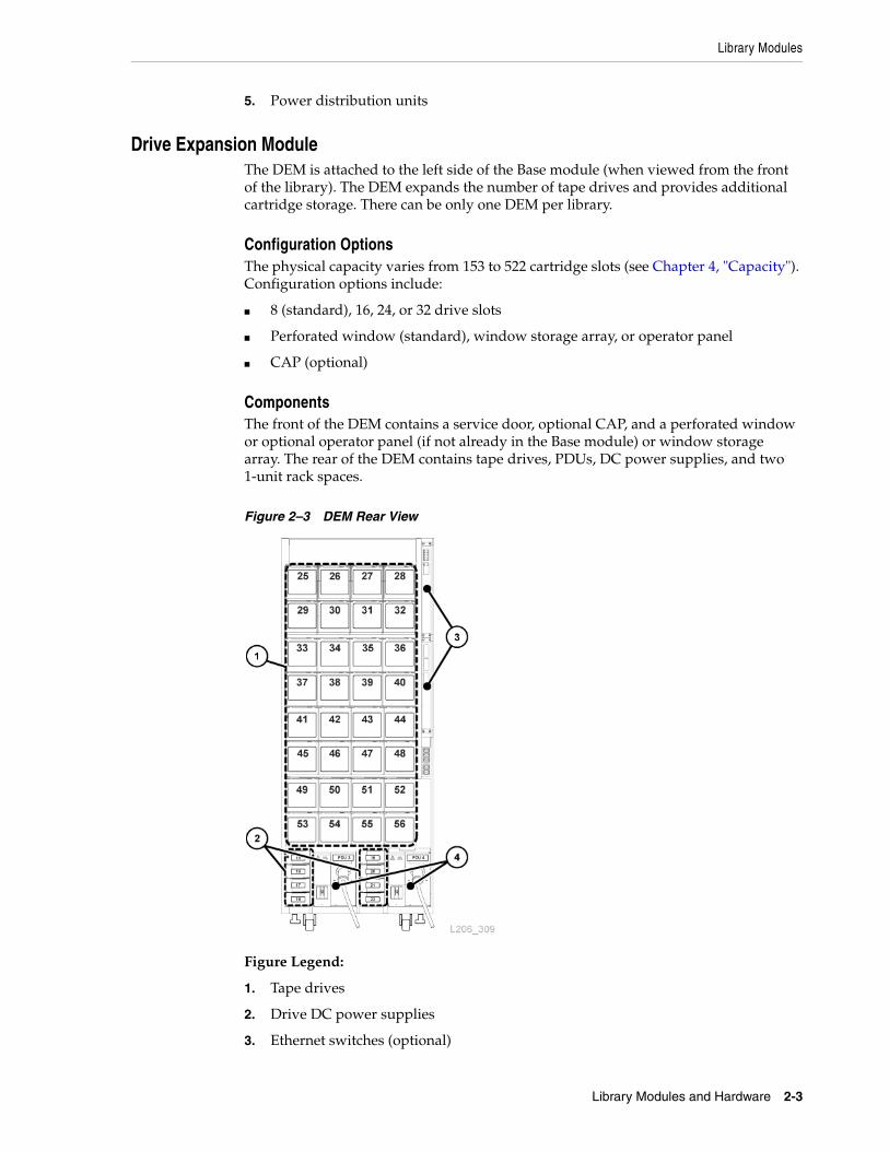
ComponentsThe front of the DEM contains a service door, optional CAP, and a perforated window or optional operator panel (if not already in the Base module) or window storage array. The rear of the DEM contains tape drives, PDUs, DC power supplies, and two 1-unit rack spaces.
Figure 2–3 DEM Rear View
Figure Legend:
1. Tape drives
2. Drive DC power supplies
3. Ethernet switches (optional)

Library Modules
2-4 StorageTek SL3000 Systems Assurance Guide
4. Power distribution unit
Cartridge Expansion ModuleThe CEM provides additional cartridge storage. There are no tape drives present within this module. CEMs on the end of the library can be converted to PEMs (see "Parking Expansion Module" on page 2-4). A maximum of eight CEMs are supported in a single library. The initial CEM should be installed to the right of a Base module, then a second to the left of the DEM/Base module, a third to the right, and the fourth one to the left, and so on. This alternating method maximizes library performance.
Configuration OptionsThe physical capacity varies from 438 to 620 cartridge slots (see Chapter 4, "Capacity"). Configuration options include:
■ CAP (optional)
■ Placement to the left or right of a Base module and DEM
■ A maximum of four CEMs on each side of centerline (eight total)
Parking Expansion ModuleThe PEM is a converted CEM used in a redundant robotics configuration. The library uses the PEM to "park" a defective robot without blocking access for the operational robot. Performing maintenance on a disabled robot in a PEM is disruptive to library operations. The parking space causes six columns of cartridge arrays in the PEM to become inaccessible (three on the front wall and three on the rear wall). You do not need to remove the inaccessible arrays. The module can be restored to a CEM at anytime.
Configuration OptionsThe physical capacity varies from 230 to 312 cartridge slots depending on the configuration (see Chapter 4, "Capacity"). One PEM must be installed on each end of the library. Only the left PEM can have an optional CAP.
Figure 2–4 Parking Expansion Module
Hardware Components
Library Modules and Hardware 2-5
Figure Legend:
1. Inaccessible CAP area
2. Robot parking area (inaccessible cartridge slots)
Access Expansion ModuleAn AEM has a large cartridge access door used for bulk loading and unloading of cartridges. Additionally, two AEMs may be used to support the redundant robotics feature. A sliding safety door sections off a defective robot, allowing a service representative to access the disabled robot while the library remains online.
Configuration OptionsEach AEM supports bulk loading and unloading of up to 234 cartridges (see "Cartridge Access Ports - Bulk Load" on page 2-7). AEMs can only be placed on the ends of the library. An AEM cannot be installed directly to the left of the Base module; there must be a module in between. AEMs and PEMs cannot be installed in the same library. Configuration options include:
■ Single AEM for bulk load capabilities only. You should install a single AEM on the left for an additional 104 storage slots (see Chapter 4, "Capacity").
■ Dual AEMs for bulk load and redundant robotics support.
Hardware Components■ "Electronics Control Module" on page 2-5
■ "Robotics" on page 2-6
■ "Cartridge Access Ports - Rotational" on page 2-6
■ "Cartridge Access Ports - Bulk Load" on page 2-7
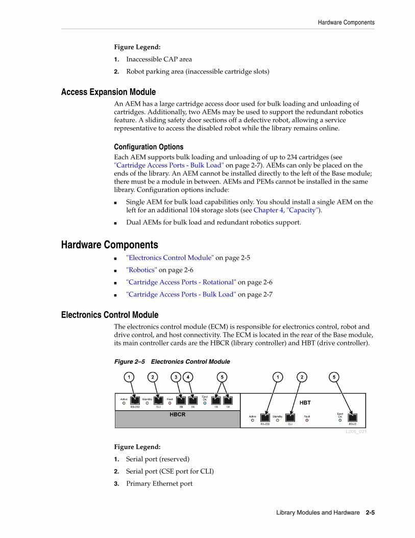
Electronics Control ModuleThe electronics control module (ECM) is responsible for electronics control, robot and drive control, and host connectivity. The ECM is located in the rear of the Base module, its main controller cards are the HBCR (library controller) and HBT (drive controller).
Figure 2–5 Electronics Control Module
Figure Legend:
1. Serial port (reserved)
2. Serial port (CSE port for CLI)
3. Primary Ethernet port

Hardware Components
2-6 StorageTek SL3000 Systems Assurance Guide
4. Dual TCP/IP Ethernet port
5. Ethernet port (reserved)
Command Line InterfaceThe command line interface (CLI) is used exclusively by Oracle support to configure and diagnose the library. Service representatives can access the CLI through the electronic control module using either of the following:
■ Serial Port Connection on the HBCR card (RS-232) and a HyperTerminal connection to enter the commands
■ Ethernet Port Connection (ports 1A, 2A, or 2B) on the HBCR card and a secure shell (PuTTY) to enter the commands
Redundant ElectronicsThe optional redundant electronics (RE) feature is available for failover protection for the HBCR controller card. With the RE feature, each library has two HBCR controller cards. If the active library controller experiences errors, operations switch automatically to the stand-by library controller, with minimal disruption to library and host operations.
RE is not available for libraries that use the direct FC-SCSI connection to hosts (refer to the SL3000 Host Connectivity Guide and the SL3000 User’s Guide).
RoboticsThe robot in the SL3000 library is called a TallBot. Each library can have either one (standard) or two TallBots (redundant robotics option). TallBots retrieve and insert cartridges into CAPs or slots and mount or dismount cartridges from tape drives.
TallBots move along two rails on the rear wall of the library. One rail is at the top of the library and one rail attaches to the floor. Two copper strips in the top rail provide power and a signal path between the TallBot and library controller (HBCR) card. Power is supplied from +48 VDC 1200 W load sharing supplies (see Chapter 5, "Power and Cooling").
TallBots contain a bar-code scanner that reads the configuration blocks in each module during library initialization and identifies volume serial numbers (VOLSERs) of cartridges during CAP entries and audits.
Redundant RoboticsThe optional redundant robotics feature increases the speed for robotic operations and allows library operations to continue if one robot fails. Redundant robotics requires 240 VAC, 2N power, and two PEMs or two AEMs.
Cartridge Access Ports - RotationalThe cartridge access port (CAP) is a vertically-mounted, rotating cylinder with two removable 13-slot magazines.
■ The Base module comes standard with a CAP.
Note: The ECM ships with an optional MPU2 card (2Gb) or PUA2 card (8 Gb) for Fibre Channel interface connections. This card is not shown in the figure but is installed below the HBCR card.

Hardware Components
Library Modules and Hardware 2-7
■ The DEM and CEMs can have one optional CAP per module. Only the left PEM can contain a CAP.
■ There can be a maximum of 10 rotational CAPs per library.
■ Each CAP has a keypad with an unlock indicator and a button to open the CAP.
Figure 2–6 Library CAPs
Figure Legend:
1. CAP (closed)
2. No CAP installed
3. CAP (open)
4. Keypad
Cartridge Access Ports - Bulk LoadAEMs allow the customer to add cartridges in bulk, up to 234 cartridges on each side, without disrupting library operations. Only one AEM is required in a library to support the bulk loading feature (see "Access Expansion Module" on page 2-5).

Hardware Components
2-8 StorageTek SL3000 Systems Assurance Guide

3
Software and Connectivity 3-1
3Software and Connectivity
This chapter provides information on library connectivity and software options:
■ Host Connectivity
■ Media Validation
■ Library Monitoring
■ Library Management Software
■ Other Storage System Solutions
Host ConnectivityThe SL3000 library supports two types of host connections:
■ Small computer system interface over a physical Fibre Channel interface (FC-SCSI)
■ Ethernet using 10/100 Base-T and CAT-5 cable (TCP/IP)
In a non-partitioned configuration, the library can use only one interface type, either FC-SCSI or TCP/IP. In a partitioned configuration, the library can have one interface type per partition.
FC-SCSI ConnectionA PUA2 Fibre Channel (FC) card must be purchased to provide a FC-SCSI connection to the library. The card provides a single or optional dual port feature, with an 8 Gb connection.
The SL3000 Interface Reference Manual contains information about the SCSI command set, FC operations, command implementations, topologies, cables, and connectors.
Supported Topologies■ Switched Fabric — Oracle recommends this topology. It provides dynamic
inter-connections between nodes and multiple, simultaneous FC connections. If the library is connected to a FC switch or fabric-capable host, it configures itself as a switched topology and can support up to 16 million ports logged into the fabric.
■ Arbitrated Loop — While the library supports the arbitrated loop topology, Oracle does not recommend it. This topology provides multiple connections for devices that share a single loop and allows only point-to-point connections between an initiator and target during communications. An arbitrated loop can connect only up to 126 ports.
Media Validation
3-2 StorageTek SL3000 Systems Assurance Guide
TCP/IP ConnectionThe TCP/IP connection provides the host library interface (HLI) used to communicate with library management applications, such as:
■ Open system platforms with ACSLS
■ Enterprise-level mainframes with ELS /HSC
The library controller card is responsible for coordinating all component operations within the library and providing the interface connection with the host. There are two separate Ethernet connections for host to library communications—Ports 2A and 2B.
■ Port 2B provides the primary host connection (standard).
■ Port 2A provides the dual TCP/IP connection (optional) or can be connected to StorageTek Library Console (SLConsole).
The dual TCP/IP feature uses both ports to provide two connections between the library and ACSLS or ELS/HSC host(s), eliminating a single point of failure. For more information, refer to the SL3000 Host Connectivity Guide.
Port BondingPort bonding combines multiple ports to create redundancy. The SL3000 library uses an active-backup mode. In active-backup mode, there is one bond with two slave Ethernet interfaces. If the active interface fails, the backup interface becomes active. With minimum library firmware FRS_4.30 and a second Ethernet switch installed in the library, port bonding is automatically enabled—no command or activation file is required.
Media ValidationMedia validation allows you to verify all T10000 tape cartridge types using SLConsole or minimum version 2.0 of StorageTek Tape Analytics (STA). The following validation methods are available: Basic Verify, Standard Verify, and Complete Verify. Media validation provides a "pass" or "suspect" result for each tape cartridge tested.
Media validation requires a designated pool of T10000C or T10000D tape drives. Up to ten drives can be placed in the media validation pool using SLConsole. The drives in the pool are not available to hosts. The pool is not considered a partition and does not contain cartridges.
The media validation feature requires minimum firmware SL3000 FRS_4.30 and SLConsole FRS_6.50. For more information about media validation using SLConsole, refer to the SL3000 User's Guide on OTN. For more information about media validation using STA, refer to the STA documentation on OTN.
Library MonitoringThe library can be monitored using SLConsole or Simple Network Management Protocol (SNMP). Additionally, service representatives can use the Log SnapShot feature to collect logs from the controller cards.
StorageTek Library ConsoleSLConsole is a software application used to manage and monitor an SL3000 library. SLConsole can be accessed from the local operator panel, a standalone version on a

Library Management Software
Software and Connectivity 3-3
workstation, or through the web-based SLConsole. For installation requirements and additional information, refer to the SL3000 User’s Guide.
Simple Network Management ProtocolSNMP is an application layer protocol that performs network management operations over an Ethernet connection. SNMP allows libraries to inform the system administrator of potential problems and system administrators to query the library for configuration, operation, and statistical information using SNMP traps. The SL3000 library supports SNMP v2c and SNMP v3 (preferred).
This functionality requires the use of a Management Information Base (MIB) on the controller card. The MIB contains information that specifically describe the library, components, and configuration. For more information, refer to the SL3000 SNMP Reference Guide.
Log SnapShot FeatureThe Log SnapShot feature is a utility that gathers, compresses, and encrypts logs from a given controller card or from an entire library such as the SL3000 library. A log snapshot can be generated using the CLI or SLConsole. Only authorized Oracle engineers or service representatives have access to the data obtained from the Log SnapShot utility.
Library Management SoftwareLibrary management software controls the library hardware and manages the library database. When the library is operating in automated mode, cartridge mount and dismount operations occur without manual intervention. Using audit data uploaded from the library, the software:
■ Tracks volume identifiers (vol-ids), attributes, and locations of cartridges
■ Allocates drives and requests library operations, such as entering, mounting, dismounting, and ejecting cartridges
Automated Cartridge System Library Software (ACSLS)ACSLS is a centralized, multi-platform library management software product for an open-systems environment. ACSLS manages all library operations and shares library resources with any ACSLS-enabled application. A single instance of ACSLS can manage multiple libraries. The key benefits of ACSLS include:
■ Centralized library control across multiple StorageTek libraries, including legacy technology
■ Optimized library performance by load-balancing hardware and executing parallel commands
■ Reduced downtime through dynamic configuration capabilities and queuing commands during short-term library outages
■ Enriched reporting and management capabilities for ease of use
ACSLS version 7.3 or greater is required for interfacing with the SL3000 library. ACSLS 7.3 requires PUT 0801 for AEM support.

Other Storage System Solutions
3-4 StorageTek SL3000 Systems Assurance Guide
Enterprise Library SoftwareEnterprise Library Software (ELS) incorporates multiple software products to monitor and manage tape libraries and virtual solutions for a mainframe environment.
Host Software Component (HSC) and Storage Management Component (SMC)HSC manages volume pools and communication with the SL3000 library. HSC resides on the host, but is transparent to the operating system. A separate component, SMC, provides the interface between z/OS operating systems and HSC. SMC resides on all MVS hosts that perform tape processing with HSC. HSC and SMC work together to influence allocations and determine policies, volume locations, and drive ownership. HSC and SMC translate user requests into library commands and provide message handling.
Virtual Tape Control System (VTCS)VTCS is the host software that enables centralized management of StorageTek virtual tape libraries, such as Virtual Storage Manager (VSM) and Virtual Library Extension (VLE). VTCS manages virtual tape volumes and drives, which includes the migration and recall of virtual volumes and the use of real tape cartridges and drives.
Concurrent Disaster Recovery Test (CDRT)CDRT enables disaster recovery testing while the library or virtual storage is in use.
Independent Software Vendors (ISVs)There are a variety of ISVs that have tested their applications and support the SL3000 library. Most ISV applications connect through ACSLS or direct-attach. Some applications include:
■ BakBone NetVault
■ CA ArcServe
■ HP Data Protector
■ Legato NetWorker
■ SAM FS
■ Tivoli Storage Manager
■ Veritas BackupExec
■ Veritas Netbackup
Not every application is tested on every platform or version. To make sure the software is supported, contact an Oracle marketing or sales representative, or application vendor. Oracle representatives can check compatibility with the Interoperability Tool at: http://tapeinterop.us.oracle.com.
Other Storage System SolutionsThe SL3000 library is compatible with several other Oracle products to provide a multifaceted storage solution. This list is not all-inclusive. For more information, contact an Oracle sales representative or visit:
http://www.oracle.com/us/products/servers-storage/storage/tape-storage/overview/index.html

Other Storage System Solutions
Software and Connectivity 3-5
Client System Component (CSC)The client system component (MVS/CSC) allows SMC on MVS to use ACSLS as its library server. One CSC is Library Station, which allows an open systems client to use HSC on MVS as its library server.
Expert Performance ReporterExpert Performance Reporter (ExPR) software collects performance data and generates reports about status and performance. It provides information on manual tape systems, as well as Nearline and VSM tape systems. ExPR has both an MVS component and a PC component.
Extended High Performance Data MoverExtended High Performance Data Mover (ExHPDM) is utility software that performs high-speed backup and restore of data sets by interleaving very large block sizes on high-speed, high-capacity tape devices. ExHPDM achieves its speed by treating all data equally regardless of the type. Its only function is to move data from disk to tape and back again.
The ExHPDM software moves blocks of data in parallel from several concurrently executing MVS application programs. The data from the application programs is buffered into 256 KB tape block sizes in the application program's address space, and the 256 KB blocks are interleaved onto single or multiple tape volumes.
Library Content Manager (LCM)Library Content Manager (LCM) — formerly Expert Library Manager (ExLM) — manages Nearline and VSM resources. LCM optimizes overall performance by assuring there are adequate resources available for a scheduled job. LCM also includes LCM Explorer, a graphical user interface that allows a user to configure LCM by creating configuration files instead of parameter files.
Linear Tape File System (LTFS)LTFS software improves file access and portability of data on StorageTek T10000 or LTO media. LTFS software enables applications to write and retrieve files directly from tape through standard file format interfaces: CIFS or POSIX. Files may also be accessed with ease through a browser or operating system graphical interface. Users can drag and drop files to and from any storage medium: disk, tape, or flash.
Oracle’s Linear Tape File System, Library Edition (LTFS-LE) software supports the SL3000 tape library, managing multiple tape drives and media. When a user selects a file, the library automatically mounts the corresponding tape and the file is made available to that application.
StorageTek Tape AnalyticsOracle's StorageTek Tape Analytics (STA) is an intelligent monitoring application available for StorageTek Modular Tape Libraries. It simplifies tape storage management so you can make informed decisions about future tape storage investments based on the current health of the tape storage environment.
STA can monitor multiple libraries from a single, browser-based user interface. STA supports open systems and mainframe, mixed-media, and mixed-drive environments across multiple library platforms. Using STA, you can increase the utilization and

Other Storage System Solutions
3-6 StorageTek SL3000 Systems Assurance Guide
performance of tape investments by performing detailed performance trending analyses. These analyses are based on a regularly updated database of library operations.
Virtual Storage Manager (VSM)VSM stores virtual tape volumes on a disk buffer called the Virtual Tape Storage Subsystem (VTSS). VSM then migrates the virtual tape volumes to tape media mounted on real tape drives in the library. This optimizes access time and throughput of data to physical tape media. The primary host software for VSM is the Virtual Tape Control System (VTCS). VTCS manages virtual tape volumes and drives, which includes the migration and recall of virtual volumes and the use of real tape cartridges and drives.
Virtual Library Extension (VLE)Virtual Library Extension (VLE) can be added to a VSM for additional capacity. VLE provides an economical second tier of disk storage that can be used to boost the overall VSM storage capacity or to use VSM as a tapeless virtual library.
4
Capacity 4-1
4Capacity
There are two types of capacity:
■ Physical Capacity — the number of cartridge slots in the library, excluding reserved slots.
■ Active Capacity — the number of slots in the library activated by an activation file. Only activated slots can be used for data storage and accessed by a client. Inactivated slots are not recognized by the library.
Oracle recommends adding physical capacity in advance to meet future storage needs. Although modules can be added to an SL3000 library at any time, adding a module is disruptive to library operations.
A diagram of the slot locations within each module can be helpful for understanding capacity. For wall maps, refer to the SL3000 User's Guide.
Physical CapacityPhysical storage capacity can range from 205 to 5,925 data cartridge slots depending on the library configuration. The capacity of a module depends on its position relative to other modules and the add-on features selected. Review the configuration options in Chapter 2, "Library Modules and Hardware".
Use the table below to calculate the physical capacity of a library. Start with the standard configuration slot count, then either add or subtract slots from the standard slot count to reflect the module position and add-on options. Finally, add the slot counts of each module together to get the total slot count for the library.
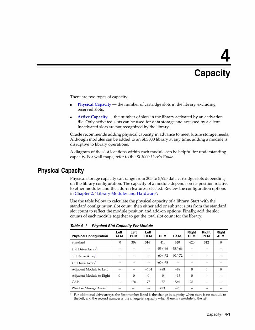
Table 4–1 Physical Slot Capacity Per Module
Physical ConfigurationLeft AEM
Left PEM
Left CEM DEM Base
Right CEM
Right PEM
Right AEM
Standard 0 308 516 410 320 620 312 0
2nd Drive Array1
1 For additional drive arrays, the first number listed is the change in capacity when there is no module to the left, and the second number is the change in capacity when there is a module to the left.
-- -- -- -55/-66 -55/-66 -- -- --
3rd Drive Array1 -- -- -- -60/-72 -60/-72 -- -- --
4th Drive Array1 -- -- -- -65/-78 -- -- -- --
Adjacent Module to Left -- -- +104 +88 +88 0 0 0
Adjacent Module to Right 0 0 0 0 +13 0 -- --
CAP -- -78 -78 -77 Std. -78 -- --
Window Storage Array -- -- -- +23 +23 -- -- --

Physical Capacity
4-2 StorageTek SL3000 Systems Assurance Guide
Calculation Example 1: Base, DEM, CEMs, PEMsThe example library has a Base module, a DEM, two CEMs (one on each side of centerline), and two PEMs (one on each end of the library).
Base moduleContains an op panel and three drive arrays. There are modules to the right and left.
320 (standard) + 0 (op panel) + 13 (right module) + 88 (left module) – 66 (2nd drive array) – 72 (3rd drive array) = 283
DEMContains a window array, a CAP, and four drive arrays. There is a module to the left.
410 (standard) + 88 (left module) + 23 (window array) – 77 (CAP) – 66 (2nd drive array) – 72 (3rd drive array) – 78 (4th drive array) = 228
Left CEMThe module is installed left of centerline. There is a module to the left.
516 (standard) + 104 (left module) = 620
Right CEMContains a CAP. The module is installed right of centerline with a module to the right.
620 (standard) – 78 (CAP) = 542
PEMsThere are two PEMs, one on each end of the library. The left PEM contains a CAP.
313 (standard right PEM) + 308 (standard left PEM) - 78 (CAP) = 542
Library Total283 (Base) + 228 (DEM) + 620 (left CEM) + 542 (right CEM) + 542 (PEMs) = 2,215
Calculation Example 2: Base and CEMThe example library has a Base module and a CEM to the right of centerline.
Base moduleContains a window array and three drive arrays. There is a module to the right.
320 (standard) + 13 (right module) + 23 (window array) – 55 (2nd drive array) – 60 (3rd drive array) = 241
Right CEMContains a CAP. The module is installed right of centerline with a module to the left.
516 (standard) + 104 (left module) – 78 (CAP) = 542
Library Total241 (Base) + 542 (right CEM) = 783
Calculation Example 3: Base, DEM, CEMs, AEMThe example library has a Base module, DEM, two CEMs (one on each side of centerline), and a single AEM on the right for bulk loading. Oracle does not recommend installing a single AEM on the right. If the AEM was installed on the left end of the library, 104 additional cartridge slots would be accessible in the far left CEM.

Active Capacity
Capacity 4-3
Base moduleContains window array and two drive arrays. There are modules to the right and left.
320 (standard) + 23 (window array) + 13 (right module) + 88 (left module) – 66 (2nd drive array) = 378
DEMContains an op panel and three drive arrays. There is a module to the left.
410 (standard) + 88 (left module) + 0 (op panel) – 66 (2nd drive array) – 72 (3rd drive array) = 360
Left CEMModule is installed left of centerline with no module to the left.
516 (standard) = 516
Right CEMModule is installed right of centerline with modules to the right and left.
516 (standard) + 104 (left module) = 620
AEMModule is installed right of centerline (not recommended for single AEM).
0 (standard) = 0
Library Total378 (Base) + 360 (DEM) + 516 (left CEM) + 620 (right CEM) + 0 (AEM) = 1,874
Active CapacityThe SL3000 library uses Capacity on Demand and RealTime Growth to allow customers to instantly increase and activate capacity without disruption.
RealTime GrowthRealTime Growth allows physical capacity to be pre-installed and then activated as needed. Additional library modules are installed during the initial installation. Then, through Capacity on Demand, the customer pays to activate slots when additional capacity is necessary. No additional physical library components are required.
Capacity on DemandCapacity on Demand is non-disruptive, allowing you to increase capacity within the library by activating previously-installed, yet inactive slots. You can upgrade capacity in 25, 100, 200, 500, and 1000 slot increments. To activate a capacity upgrade, a hardware activation file is required (see "Hardware Activation Files" on page 9-1).
Changes to active capacity result in minimal disruptions to library operations. The specific library behavior depends on the type of host connection, HLI or FC-SCSI (refer to SL3000 User's Guide). It is recommended that you make the library unavailable to other user requests before committing the active storage region changes.

Active Capacity
4-4 StorageTek SL3000 Systems Assurance Guide

5
Power and Cooling 5-1
5Power and Cooling
All power supplies and power distribution units (PDUs) reside in the Base module and DEM. When selecting a power configuration, consider any power redundancy requirements along with the features and number of drives that will be supported in the library.
■ Power Configurations
■ DC Power Supplies
■ Calculating Tape Drive Power Supply Quantities
■ AC Power Cables
■ Power Consumption
■ Cooling
Power ConfigurationsThe power configuration depends on the power source and the power redundancy.
AC Power Source OptionsEach PDU installed in the library requires a separate AC power source. There can be a maximum of four PDUs in the library depending on the configuration selected (two in the Base module and two in the DEM). There are two AC power source options. Both are single phase:
■ 120 VAC, 50/60 Hz, at 20 amps (range: 100–127 VAC, 47–63 Hz, 16 amps)
– Limited support for T9840 and T10000 drives; no redundant robotics support
■ 240 VAC, 50/60 Hz, at 30 amps (range: 200–240 VAC, 47–63 Hz, 24 amps)
– Supports all drive types and redundant robotics
Power Redundancy OptionsThere are three power configurations that offer various levels of power redundancy.
N+1 power configuration (standard) ■ Offers DC power redundancy only
■ Consists of one PDU (per Base module or DEM), with one extra drive DC supply and one extra robotics DC supply
■ Provides N+1 DC power supply redundancy

DC Power Supplies
5-2 StorageTek SL3000 Systems Assurance Guide
■ Limited support for T9840 and T10000 drives and no redundant TallBot support
2N power configuration■ Offers both AC and DC power redundancy
■ Consists of two PDUs (per Base module or DEM) for AC redundancy, with a set of DC power supplies for each PDU
■ Provides N DC power supplies per PDU
■ Requires two separate AC input sources per Base module or DEM
■ Required for redundant TallBot and redundant electronics support
2N+1 power configuration■ Offers both AC and DC power redundancy with additional DC redundancy
■ Consists of two PDUs (per Base module or DEM) for AC redundancy, with additional DC power supplies for each PDU
■ Provides N+1 DC power redundancy for each PDU (except the second PDU only has N DC power supply redundancy for the TallBot)
■ Requires two separate AC input sources per Base module or DEM
■ Supports redundant TallBot and redundant electronics
DC Power SuppliesThere are two types of DC power supplies:
■ Load sharing 1200W DC — used for the robotics unit and tape drives
■ 200W cPCI — used for the electronics control module

DC Power Supplies
Power and Cooling 5-3
Figure 5–1 Power Supply Locations - Base and DEM (Rear View)
Figure Legend:
1. Robotics DC power supplies (1200W DC)
2. Electronics module DC power supplies (200W cPCI)
3. Tape drive DC power supplies (1200W DC)
4. Power distribution unit (120 VAC or 240 VAC)
Electronic Control Module Power SuppliesThe electronics control module (ECM) uses 200 W cPCI power supplies. These power supplies are located below the HBT card in the Base module (there are no ECM power supplies in the DEM) — see Figure 5–1. The power supply for the electronics control module is different from the power supplies used for the robotics unit and the tape drives.
Each Base module ships standard with two ECM power supplies used for N+1 and 2N configurations. Order two additional ECM supplies for the 2N+1 configuration (see "DC Power Supplies" on page 9-9).
Robotics Unit Power SuppliesThe robotics unit uses load sharing 1200 W DC power supplies located at the top of the Base module (the DEM does not contain robotics DC supplies) — see Figure 5–1. The 1200 W DC power supply used for the robotics unit is the same power supply used for the tape drives.
Each Base module ships standard with two robotics DC power supplies used for N+1 and 2N configurations. Order a third DC power supply for the 2N+1 configuration (see "DC Power Supplies" on page 9-9).

Calculating Tape Drive Power Supply Quantities
5-4 StorageTek SL3000 Systems Assurance Guide
Tape Drive Power SuppliesThe tape drives use load sharing 1200 W DC power supplies. Up to four tape drive power supplies are located to the left of each PDU in both the Base module and the DEM — see Figure 5–1.
The library ships with two tape drive DC power supplies per Base module and two tape drive DC power supplies per DEM. The number of tape drive DC power supplies required depends on the power configuration selected and the number and type of tape drives in the library. To calculate the number of power supplies to order, see "Calculating Tape Drive Power Supply Quantities" below.
Calculating Tape Drive Power Supply QuantitiesThe number of supplies required, depends on:
■ Power configuration (120 VAC or 240 VAC with N+1, 2N, or 2N+1)
■ Number and type of tape drive (T10000, T9840, or LTO)
To determine the number of power supplies required for a library configuration:
1. Determine the total number of each drive type.
2. Multiply by the watts-per-drive for each drive type, see Table 5–1, " Watts Per Drive".
3. Add together the watts used by each drive type to calculate the total watts consumed.
4. Use Table 5–2 through Table 5–5 to determine the number of DC power supplies needed.
For ordering part numbers, see "DC Power Supplies" on page 9-9.
Watt Consumption Per Drive
Power Supplies Required for 120 VAC PDUsTo use 120 VAC PDUs, the total watts used by the drives must be less than 843 W in the Base module and less than 1,481 W in the DEM. If the total watts exceeds 843 W in the Base module or 1,481 W in the DEM, 240 VAC PDUs are required. You cannot mix 120 VAC with 240 VAC PDUs within the library. All PDUs must be the same type.
Table 5–1 Watts Per Drive
Drive TypeMaximum Watts Used by Each Drive
T9840D 100
T10000A/B/C 93
T10000D 127
LTO 46
Table 5–2 DC Power Supplies for Base (120 VAC PDU)
Total Watts Used by All Drives
Power Supplies Required for N+1
Power Supplies Required for 2N
Power Supplies Required for 2N+1
1 - 563 2 2 4
Calculating Tape Drive Power Supply Quantities
Power and Cooling 5-5
Power Supplies Required for 240 VAC PDUsIf the total watts used by the drives exceeds 843 W in the Base module or 1,481 W in the DEM, 240 VAC PDUs are required. You cannot mix 120 VAC with 240 VAC PDUs within the library. All PDUs must be the same type.
Example: Calculating Required Number of Drive DC Power SuppliesThe sample library has a Base module and a DEM with all three drive types (T10000, T9840, LTO). Table 5–6 and Table 5–7 show how to calculate the total watts used by the tape drives in the Base module and DEM:
564-843 3 4 6
Table 5–3 DC Power Supplies for DEM (120 VAC PDU)
Total Watts Used by All Drives
Power Supplies Required for N+1
Power Supplies Required for 2N
Power Supplies Required for 2N+1
1 - 700 2 2 4
701 - 1,400 3 4 6
1,401-1,481 4 6 8
Table 5–4 DC Power Supplies for Base (240 VAC PDU)
Total Watts Used by All Drives
Power Supplies Required for N+1
Power Supplies Required for 2N
Power Supplies Required for 2N+1
1 - 1,063 2 2 4
1,064 - 2,263 3 4 6
2,264 - 3,463 4 6 8
3,464 - 3,805 5 8 8
Table 5–5 DC Power Supplies for DEM (240 VAC PDU)
Total Watts Used by All Drives
Power Supplies Required for N+1
Power Supplies Required for 2N
Power Supplies Required for 2N+1
1 - 1,200 2 2 4
1,201 - 2,400 3 4 6
2,401 - 3,600 4 6 8
3,601 - 4,443 5 8 8
Table 5–6 Base Module Tape Drive Watts Consumption Example
Drive Type Quantity of DrivesMultiply by Watts Per Drive
Total Watts Per Drive Type
T10000D 6 127 762
T9840D 6 100 600
LTO4 4 46 184
Table 5–2 (Cont.) DC Power Supplies for Base (120 VAC PDU)
Total Watts Used by All Drives
Power Supplies Required for N+1
Power Supplies Required for 2N
Power Supplies Required for 2N+1
AC Power Cables
5-6 StorageTek SL3000 Systems Assurance Guide
The drives in the Base module use 1,546 W. In Table 5–2, 1,546 W exceeds the maximum 843 W supported by a 120 VAC PDU. Therefore, the Base module requires a 240 VAC PDU to support the drive configuration, so refer to Table 5–4.
The drives in the DEM use 756 W. In Table 5–3 and Table 5–5, either a 120 VAC or 240 VAC PDU can support 756 W. However, you cannot mix 120 VAC with 240 VAC PDUs within the library. Therefore, the example library requires 240 VAC PDUs.
Two tape drive DC power supplies ship standard with the Base module and two power supplies ship standard with the DEM. Therefore, subtract two from the DC supplies required. Use Table 5–4 and Table 5–5 to determine what to order.
The tables below list the power supplies required for the example library.
The number of drive DC supplies that must be ordered depends on the power configuration selected. For instance, if the example library had a 2N+1 configuration, it would require an order of six additional drive DC power supplies (four supplies for the Base module and two supplies for the DEM). The 2N+1 also requires an additional DC supply for the robotics and an additional ECM 200W cPCI power supply. The ECM power supply is different than the tape drive and robot power supplies listed in this example. For ordering information, see "DC Power Supplies" on page 9-9.
AC Power CablesThe following table lists the cables required for each power configuration. You must order one power cord per PDU installed:
■ For N+1 order one power cord for the Base module and an additional power cord for the DEM (if installed)
Table 5–7 DEM Tape Drive Watts Consumption Example
Drive Type Quantity of DrivesMultiply by Watts Per Drive
Total Watts Per Drive Type
T10000C 4 93 372
T9840D 2 100 200
LTO5 4 46 184
Table 5–8 DC Supplies Required for Base Example
Configuration OptionDC Supplies Required
DC Supplies to Order (= Required - 2)
N+1 (240 VAC PDU) 3 1
2N (240 VAC PDU) 4 2
2N+1 (240 VAC PDU) 6 4
Table 5–9 DC Supplies Required for Drive Expansion Module - Example
Configuration OptionDC Supplies Required
DC Supplies to Order (= Required - 2)
N+1 (240VAC PDU) 2 0
2N (240VAC PDU) 2 0
2N+1 (240VAC PDU) 4 2

Power Consumption
Power and Cooling 5-7
■ 2N or 2N+1: Two power cords for the Base module and two additional power cords for the DEM (if installed)
Power ConsumptionFor environmental or economical reasons, you may want to determine the total power consumption (watts), CO2 emission values, and British Thermal Units (Btu/hr) for the SL3000 library and tape drives. The table below provides power consumption in watts.
Calculating Total Watts, CO2 Emissions, and Btu/hrTo calculate the total power consumption in Watts for the library, add up all the applicable wattage values for the library configuration from Table 5–11.
To calculate kilograms of CO2 emissions per day, multiply watts by the CO2 emissions constant. Use the constant that is applicable for your country (0.02497 for US).
To convert electrical values to Btu/hr, multiply the number of watts by 3.412 (1 W =3.412 Btu/hr). Many manufacturers publish kW, kVA, and Btus for their equipment. Use the information provided by the manufacturer. Otherwise, use the formula below.
■ 3.41214 x Watts =Btu/hr
Power Consumption Example 1Using the maximum continuous values for the following components:
Table 5–10 Power Cable Descriptions
Power Source DescriptionCircuit Breaker
Wall Connector
Library Connector
Power Cord
Length/Type
120 VAC/20A US/Japan 20A L5-20P L5-20R 3.7 m (12 ft) 12 AWG
240 VAC/30A US 30A L6-30P L6-30R 3.7 m (12 ft) 12 AWG
240 VAC/30A International 30A 330P6W L6-30R 4 m (13 ft) HAR
Table 5–11 Power Consumption Values
Components Quantity Idle Watts Max Watts
Base Library (required)
Includes: 1 ECM, 1 robot, and 1 CAP
1 156 197
Redundant Electronics (optional) 1 100 100
Redundant Robotics (optional) 1 28 55
Operator Panel (optional) 1 29 37
Additional CAPs (optional) Each 10 14
Access Expansion Module (optional) Each 8 30
T9840 Each 79 100
T10000A/B/C Each 61 93
T10000D Each 64 127
LTO Each 30 46

Cooling
5-8 StorageTek SL3000 Systems Assurance Guide
■ Emissions: 933W x 0.02497 = 23.3 Kg of CO2
■ Power consumption: 933W x 3.412 = 3,183 Btu/hr
Power Consumption Example 2Using the maximum continuous values for the following components:
■ Emissions: 1,771W x 0.02497 = 44.2 Kg of CO2
■ Power consumption: 1,771W x 3.412 = 6,043 Btu/hr
CoolingCooling within the SL3000 library is divided into three areas:
■ Electronics control module
■ Tape drives
■ DC power supplies
Library Electronics Control ModuleTwo fans, located to the right of the electronics control module, provide cooling for the electronics in the library. Air is drawn from the sides of the library and flows through the fans to the rear of the library.
■ The library controller card (HBCR) monitors these fans for proper operation.
■ An amber Fault indicator is on the fan assembly to indicate a failure.
While there are two dedicated fans, one fan is sufficient to provide adequate cooling for the library and the electronics. The fans can be replaced without interfering with library operations. Therefore, replace a defective fan when it is detected.
Table 5–12 Power Consumption Example
Quantity Component Description Watts
1 SL3000 Base (including one ECM, one robot, one CAP) 197
16 LTO4 Tape Drives 736
-- Total 933
Table 5–13 Power Consumption Example
Quantity Component Description Watts
1 SL3000 Base (including one ECM, one robot, one CAP) 197
8 T9840D Tape Drives 800
1 Drive Expansion Module --
8 T10000C Tape Drives 744
1 Cartridge Expansion Module --
3 CAPs (3 at 10 Watts each) 30
-- Total 1,771
Cooling
Power and Cooling 5-9
Tape DrivesEach tape drive tray contains a fan for drive cooling. The tape drive's power converter card supplies power for the fans. Air is drawn from the front of the drive and flows through the fan to the rear of the drive/library.
DC Power SuppliesEach 1200 Watt DC power supply contains a fan that pulls air from the library, through the rear of the supply, and out the rear of the library.

Cooling
5-10 StorageTek SL3000 Systems Assurance Guide

6
Systems Assurance 6-1
6Systems Assurance
The system assurance process is the exchange of information between the customer and Oracle representatives to ensure that no aspects of the sale, order, installation and implementation for the SL3000 library are overlooked. This process promotes an error-free installation and contributes to overall satisfaction.
■ System Assurance Planning
■ Engagement Methodology
System Assurance PlanningThe purpose of the system assurance planning is to:
■ Introduce you to the SL3000 library.
■ Explain the system assurance process and establish the team.
■ Identify and define requirements and configurations.
■ Complete the order.
■ Prepare for the installation and implementation.
Engagement MethodologyOracle has standardized and implemented a delivery methodology that provides continuity and quality assurance. Sales personnel can provide a series of templates and checklists to ensure that the proposed solution can be delivered and supported. Following this methodology allows Oracle marketing, sales, and engagement personnel to provide consistent documentation for each engagement and to ensure both customer satisfaction and overall sales success.
Actions for Sales Personnel■ Introduce the team members and exchange contact information.
■ Describe the SL3000 modular library, options, and features.
■ Identify and define the customer's requirements and expectations.
■ Identify any additional items the customer might need:
– Library management software and additional hardware activation files, media, tape drives, drive tray conversions, encryption, network components and cables, and service delivery platform (SDP)

Engagement Methodology
6-2 StorageTek SL3000 Systems Assurance Guide
■ Make sure the site is ready to receive the SL3000 library. Review the information in Chapter 7, "Site Planning" and Chapter 8, "Installation Planning".
■ Review and complete the site survey, found at: http://my.oracle.com/site/pd/sss/products/tape/index.html
■ Place an order, see Chapter 9, "Ordering".
■ Install and implement that solution by providing qualified service and support.

7
Site Planning 7-1
7Site Planning
This chapter provides planning information and requirements to consider before installing the SL3000 library. Key planning considerations include:
■ Networking
■ Physical Dimensions and Weights
■ Floor Requirements
■ Fire Suppression Planning
■ Cable Routing
■ Environmental Requirements
NetworkingIf possible, use a dedicated and secure private network for communication between the library and host management software. A secure private network connection using an Ethernet hub or switch is required for maximum throughput and minimum resource contention.
If a shared network must be used:
■ Place the library on its own subnet.
■ Directly connect the library to a switch and use a managed switch that can:
– Set priorities on ports to give the host and library higher priority.
– Provide dedicated bandwidth and create a VLAN between the host and the library.
■ Use a virtual private network (VPN) to insulate host and library traffic.

Physical Dimensions and Weights
7-2 StorageTek SL3000 Systems Assurance Guide
Physical Dimensions and Weights
Figure 7–1 Service Clearances and Dimensions (Top View)
Figure Legend:
1. Side cooling area
2. Side cover
3. Nozzle cutout for fire suppression system
4. Base and DEM service clearance (light gray areas)
5. AEM service clearance (dark gray areas)

Physical Dimensions and Weights
Site Planning 7-3
Figure 7–2 Service Clearances and Dimensions (Side View)
Figure Legend:
1. Base and DEM rear service clearance
2. Base and DEM front service clearance
3. AEM service clearance
4. Jack pad adjustment range
Base Module
Table 7–1 Base Module Measurements
Dimension Type Measurement
Height 196.7 cm (77.45 in.) on casters for transport
197.5 cm (77.75 in.) to 201.68 cm (79.4 in.) on jack pads for permanent install
Width 76.8 cm (30.22 in.) when placed between modules
81.3 cm (32 in.) transport width (no side covers) 1
91.5 cm (36 in.) standalone with side covers on both sides2
1 Minimum transportation clearance. There are alignment tabs on each side of the module, which add 4.5 cm to the 76.8 cm width of the module. Therefore, 81.3 cm is the minimum transportation width.
2 One side cover adds 7.4 cm (2.9 in.) to the module width. Only the ends of the library require side covers.
Depth 121.9 cm (48 in.)
Service Area Front: 45.7 cm (18.0 in.)
Rear: 81.3 cm (32.0 in.)
Side Cooling Area: 5 cm (2 in.)
Side Install Area: 45.7 cm (18.0 in.)
Weight Frame only: 361 kg (796 lb), Shipping weight: 411 kg (905 lb)
8 drives and media: 623 kg (1372 lb)
16 drives and media: 661 kg (1457 lb)
24 drives and media: 687 kg (1514 lb)
Side Covers: 18.5 kg (41 lb) per side

Physical Dimensions and Weights
7-4 StorageTek SL3000 Systems Assurance Guide
Drive Expansion Module
Cartridge and Parking Expansion Modules
Access Expansion Module
Table 7–2 Drive Expansion Module Measurements
Dimension Measurement
Height 196.7 cm (77.45 in.) on casters for transport:
197.5 cm (77.75 in.) to 201.68 cm (79.4 in.) on jack pads for permanent install
Width (module only) 76.8 cm (30.22 in.) when placed between modules
81.3 cm (32 in.) transport width (no side covers) 1
83.8 cm (33 in.) with one side cover
1 Minimum transportation clearance. There are alignment tabs on each side of the module, which add 4.5 cm to the 76.8 cm width of the module. Therefore, 81.3 cm is the minimum transportation width.
Depth (doors closed) 121.9 cm (48 in.)
Service Area Front: 45.7 cm (18.0 in.)
Rear: 81.3 cm (32.0 in.)
Side Cooling Area: 5 cm (2 in.)
Side Install Area: 45.7 cm (18.0 in.)
Weight Frame only, no CAP: 265 kg (584 lb)
Shipping (frame only): 314 kg (693 lb), 321 kg (708 lb) with CAP
8 drives and media: 540 kg (1190 lb), 582 kg (1284 lb) with CAP
16 drives and media: 596 kg (1314 lb), 621 kg (1369 lb) with CAP
24 drives and media: 647 kg (1426 lb), 660 kg (1456 lb) with CAP
32 drives and media: 709 kg (1564 lb), 723 kg (1594 lb) with CAP
Table 7–3 Cartridge and Parking Expansion Module Measurements
Dimension Measurements
Height 196.7 cm (77.45 in.) on casters for transport
197.5 cm (77.75 in.) to 201.68 cm (79.4 in.) on jack pads for permanent install
Width (module only) 76.8 cm (30.22 in.) when placed between modules/side cover
81.3 cm (32 in.) transport width (no side covers) 1
83.8 cm (33 in.) with one side cover
1 Minimum transportation clearance. There are alignment tabs on each side of the module, which add 4.5 cm to the 76.8 cm width of the module. Therefore, 81.3 cm is the minimum transportation width.
Depth 77.5 cm (30.5 in.)
Weight (CEM) Frame only: 175 kg (385 lb)
Shipping: 213 kg (469 lb)
Installed, with media: 340 kg (749 lb)
Weight (PEM) Frame only: 122.5 kg (270 lb)
Shipping: 213 kg (469 lb)
Table 7–4 Access Expansion Module Measurements
Dimension Measurement
Height 196.7 cm (77.45 in.) on casters for transport
197.5 cm (77.75 in.) to 201.68 cm (79.4 in.) on jack pads for permanent install

Floor Requirements
Site Planning 7-5
Covers, Doors, and Service Clearances
Floor RequirementsThe SL3000 library can be installed on a raised, solid, or carpeted floor with a smooth surface. There must be adequate airflow and the floor must meet environmental specifications and weight requirements. If the floor is raised, there should not be ventilation panels directly below the library. If the floor is solid, route cables from the ceiling to avoid creating a tripping hazard. If the floor is carpeted, make sure the carpet is approved for computer-room equipment and provides protection from electrostatic discharge (ESD).
WeightEnsure the site floor can support the weight of the library. It must support 454 kg (1,000 lb) per weight distribution pad, which measure 4 by 8 inches. There are four distribution pads per module.
If the equipment must be transported on elevators, the elevator cars must be capable of safely handling the weight. Depending on the library configuration the weight of the library can vary (see "Physical Dimensions and Weights" on page 7-2).
Floor Slope TallBots must travel along a level plane throughout the library. Any excessive out-of-plane conditions could cause binding, premature wear, and damage to the TallBots. Use the jack pads to adjust the library on a sloped floor.
Width 91.4 cm (36.0 in.) when placed between module and side cover
96 cm (37.8 in) transport width (no side covers) 1
99.1 cm (39 in.) with one side cover
Depth 77.5 cm (30.5 in.)
Service Area Front: 59.7 cm (23.5 in.)
Weight Frame only: 204.2 kg (450 lb)
Shipping: 260 kg (570 lb)
1 Minimum transportation clearance. There are alignment tabs on each side of the module, which add 4.5 cm to the 91.5 cm width of the module. Therefore, 96 cm is the minimum transportation width.
Table 7–5 Covers, Doors, and Service Clearance Measurements
Dimension Measurement
Height 190.3 cm (74.9 in.) frame only
Door thickness Front: 1.9 cm (0.75 in.)
Rear: 4.5 cm (1.75 in.)
Door latches 2.53 cm (0.9 in.)
Service clearance Front: 45.7 cm (18 in.) for Base and DEM only, 59.7 cm (23.5 in.) for AEM
Rear: 81 cm (32 in.) for Base and DEM only
Side: 5 cm (2 in.) for cooling, 45.7 cm (18.0 in.) for install
Side cover 7.4 cm (2.9 in.) width
18.5 kg (41 lb) each
Table 7–4 (Cont.) Access Expansion Module Measurements
Dimension Measurement

Fire Suppression Planning
7-6 StorageTek SL3000 Systems Assurance Guide
Fire Suppression PlanningThe library does not ship with a fire suppression system, but each module has a 5 cm (2 inch) diameter nozzle opening (see Figure 7–1). Plates, 7 cm (2.75 inch) square and 1.2 mm (0.048 inch) thick, cover the openings and can be drilled to custom fit nozzles. Nozzles must be clear of robotic operations and cannot protrude more than 1.9 cm (0.75 inches) into the library. Professional Services can assist with fire suppression planning (contact your Oracle sales representative).
Cable RoutingThe SL3000 library has rear door cut-outs on both the top and bottom of the door to allow for cable routing. The cut-out is a 2.5 cm (1 inches) opening that runs 73 cm (29 inches) along the length of the door with cable routing hardware and reliefs available.
When routing cables, make sure to include locations for power, drive interface, library control, and Ethernet cables. As a best practice, route power cables through one cut-out and signal cables through another cut-out.
Figure 7–3 Door Cable Routing Cutouts
Figure Legend:
1. Cable routing area
2. Top/bottom view of rear door
AC Power Configurations and CablesSL3000 libraries require that the customer select one of the following single phase AC power options for the Base module and DEM:
■ 110 VAC, 50/60 Hz, at 20 Amps (range: 100–127 VAC, 50–60 Hz, 16 Amps)
■ 240 VAC, 50/60 Hz, at 30 Amps (range: 200–240 VAC, 50–60 Hz, 24 Amps)
Make sure to plan for the locations of power cables and list the locations for their associated circuit breakers. Cables must be ordered for the appropriate power configuration. Order one power cord per PDU installed:
■ N+1: One power cord for the Base module and an additional power cord for the DEM (if installed).
■ 2N or 2N+1: Two power cords for the Base module and two additional power cords for the DEM (if installed).
Note: The Base module and DEM have two square cut-outs on the rear door. These are only for PDU power source cables, not for general cable routing.
Environmental Requirements
Site Planning 7-7
Library Network and Tape Drive CablesThe library can be used in a 62.5-micron-cable Storage Area Network (SAN). However, the cable that connects the library to the network must be a 50-micron cable. The maximum distances supported on a Fibre Channel link is determined by the link speed, the type of fiber (50 or 62.5 micron), and the device to which the library is attached. Refer to your switch vendor to determine what is supported in your storage area network.
The typical support distances for the cables are:
■ 4 Gbps = up to 70 m (230 ft) for 62.5-micron, 150 m (492 ft) for 50-micron
■ 2 Gbps = up to 150 m (492 ft) for 62.5-micron, 300 m (984 ft) for 50-micron
■ 1 Gbps = up to 175 m (574 ft) for 62.5-micron, 500 m (1640 ft) for 50-micron
If your library attaches to a host bus adapter (HBA), refer to the documentation for the HBA for the supported cable distances. For a list of cables, see "Cables" on page 9-10.
If your library will support encryption, see "Encryption Switches and Cabling" on page 9-7.
Environmental RequirementsFor optimal reliability, maintain the environment between the recommended ranges. Although this equipment is designed to operate in environmental conditions of 20% to 80% humidity, a recommended industry best practice is to maintain a relative humidity of 40% to 50%.
Power ConsumptionFor power requirements, heat output, and power consumption, see Chapter 5, "Power and Cooling".
Seismic or Earthquake RatingsThe requirements for seismic compatibility vary dramatically throughout the world. Therefore, Oracle does not offer a standard "seismic" feature for the SL3000 library. It is recommended that any customer who has seismic concerns work with local experts who are familiar with the local code and requirements. Professional Services can also be engaged to help coordinate this activity.
Table 7–6 Environmental Specifications
Description Temperature Relative Humidity (non-condensing) Wet Bulb Maximum Maximum Altitude
Operating 15 to 32°C (60 to 90°F) dry bulb
20% to 80% 29.2°C (84.5°F) 3.05 km (10,000 ft)
Storage 10 to 40°C (50 to 104°F)
10% to 95% 35.0°C (95.0°F) 3.05 km (10,000 ft)
Shipping -40 to 60°C (-40 to 140°F)
10% to 95% 35.0°C (95.0°F) 15.24 km (50,000 ft)
Caution: Bodily injury and equipment damage: A qualified seismic engineer must be consulted to verify seismic zone exposures and adequate site preparation.

Environmental Requirements
7-8 StorageTek SL3000 Systems Assurance Guide
For sites in areas of seismic activity, the customer may want to permanently fix the library position for added stability. The SL3000 library provides mounting holes in the floor of each module where half-inch carriage bolts (mounting studs) can be used to permanently fix the library's position.
Airborne Contaminants Control over contaminant levels in a computer room is an extremely important consideration when evaluating an environment. Automated tape library components and electronics, tape drives, and media are subject to damage from airborne particulates. The operating environment must adhere to the requirements of: ISO 14644-1 Class 8 environment. For more information, see Appendix B, "Controlling Contaminants".
Gasses that are particularly dangerous to electronic components include chlorine compounds, ammonia and its derivatives, oxides of sulfur and petrol hydrocarbons. In the absence of appropriate hardware exposure limits, health exposure limits must be used.
Humidification with chlorinated water is a common source of damaging airborne chlorine. Appropriately designed carbon filters must be used to ensure safe levels of airborne chlorine when chlorinated water is used for humidification.
Table 7–7 Gas Limit Recommendations
Chemical Name Formula ASHRAE OSHA (PEL) ACGIH NIOSH
Acetic Acid CH3COOH Not defined 10 ppm Not defined Not defined
Ammonia NH 3500 µg/m3 350 ppm 25 ppm Not defined
Chlorine Cl 2100 µg/m3 31 ppm (c) Not defined 0.5 ppm (c)
Hydrogen Chloride HCl Not defined 5 ppm (c) Not defined Not defined
Hydrogen Sulfide H2S 50 µg/m3 320 ppm (c) 10 ppm 10 ppm
Ozone O3 235 µg/m3 30.1 ppm Not defined Not defined
Petrol-hydrocarbons CnHn Not defined 500 ppm 75 ppm 300 ppm
Sulfur Dioxide SO2 80 µg/m3 35 ppm 2 ppm 0.5 ppm (c)
Sulfuric Acid H2SO4 Not defined 1 ppm Not defined 1 ppm (c)

8
Installation Planning 8-1
8Installation Planning
This chapter outlines requirements and planning considerations for an SL3000 library installation.
■ Physical Space
■ Time and Personnel
■ Shipping Weights and Measures
■ Pallet Double Stacking
■ Installation Tools
Physical SpaceA successful installation of the SL3000 library requires an adequate physical space. For dimensions of the library modules, see "Physical Dimensions and Weights" on page 7-2. If modules will be added in the future, ensure there is enough room to expand the library.
FloorEnsure that the weight and coplanar requirements are satisfied (see "Floor Requirements" on page 7-5).
TransportationIf the equipment must be transported on elevators, the elevator cars must be capable of safely handling the weight. Additionally, ensure that the components can pass through doorways and fit in elevators. For more information, see "Shipping Weights and Measures" on page 8-2.
Construction AreaThe minimum working area (not including the space required for the pallets) is approximately 19 m2 (200 ft2).
Waste DisposalSales and service personnel should plan with customers on the disposal of all packing material. Determine if waste bins or recycling containers will be provided on site or whether an independent company will handle the disposal at additional cost.
Time and PersonnelThe table below shows the estimated times for the installation of modules and components. At least two qualified service representatives should install the library. The times listed below do not include library initialization, testing, audits, and feature

Shipping Weights and Measures
8-2 StorageTek SL3000 Systems Assurance Guide
upgrades. Installation services are required with the purchase of the SL3000 library. Contact an Oracle sales representative for more information.
Shipping Weights and MeasuresThe SL3000 library modules and other components are shipped on pallets. The table below lists each module and its shipping specifications. If equipment on a pallet must be transported on elevators, the elevator cars must be capable of safely handling the weight.
Either a split-pallet or pallet-ramp design is used to ship and provide safe removal of the module at the customer site. SL3000 library modules are shipped with wheels (casters) already attached to allow for easy positioning within the data center. Once positioned, the modules must be raised from their wheel-base to rest upon load plates for stability and leveling purposes.
The suggested library adjustment height is 200 cm (77.6 in.). Therefore, ensure that the top of the library does not interfere with ceiling fixtures at the installation site.
Table 8–1 Installation Time Estimates
Module/Component
Time Estimate (hours)
Personnel Required
Total Person Hours
Base with 8 drives (standard) 3 2 6
Base and DEM 5 2 10
Base and CEM 4 2 8
Each additional CEM 2 2 4
Two PEMs 2 2 4
AEMs (each) 2 2 4
CAPs 1 2 2
Tape drive (each drive) 0.5 1 0.5
Operator panel or window 0.75 1 0.75
Firmware 0.2 1 0.2
Integration (cables, hubs, switches, connections) 8 1 8
Media install (each) 0.02 1 variable
Table 8–2 Module and Tape Drive Shipping Information
Type Height Width Depth Weight
Base 216 cm (85 in.) 97 cm (38.3 in.) 134 cm (53 in.) 410 kg (905 lb)
DEM 216 cm (85 in.) 97 cm (38.3 in.) 134 cm (53 in.) 321 kg (708 lb)
CEM 216 cm (85 in.) 97 cm (38.3 in.) 96 cm (38 in.) 213 kg (469 lb)
PEM 216 cm (85 in.) 97 cm (38.3 in.) 96 cm (38 in.) 213 kg (469 lb)
AEM 216 cm (85 in.) 97 cm (38.3 in.) 148 cm (58 in.) 260 kg (570 lb)
LTO 32 cm (12.6 in.) 31 cm (12.2 in.) 66 cm (26 in.) 9.5 kg (20.9 lbs)
T10000 34 cm (13.4 in.) 31 cm (12.2 in.) 66 cm (26 in.) 10.5 kg (23.1 lbs)

Installation Tools
Installation Planning 8-3
Pallet Double Stacking
In the event that a forklift is unavailable to safely remove the module, notify the installation coordinator. Inform them that the library may need to be picked up from the site by the delivery company, taken off the second pallet, and re-delivered. Delivery personnel are not authorized to remove the modules from the second pallet without the proper equipment.
Installation ToolsThe tables below lists the installation tools required for the SL3000 library. Obtain the standard tools locally or from the SL8500 installation kit if available.
WARNING: Possible Physical Injury. Only use a forklift operated by a qualified operator to remove a stacked second pallet. Do not attempt to tilt or slide the pallet off by hand.
Table 8–3 Standard Installation Tools
Standard Tools Use
Torx screwdriver with T8, T10, T15, T25 bits T8: Removal and replacement of the PUK card.
T10: PUO, PUW, PUN, PUF, PUZ cards. Track stops.
T15: Operator panel, window, blank plate, arrays
T25: Shipping brace, rails, and CAP screws.
3/8-in. drive ratchet wrench1
1 Can be obtained from the SL8500 tool kit.
Module height adjustment, joining modules
5/16-in. hex Allen on 3/8-in. drive1 Module height adjustment, joining modules
9/16-in. socket on 3/8-in.-drive1 Module removal from pallet
Adjustable wrench (must accept 7/8-in. nut)
Lock weight distribution pads
Phillips and flat blade screwdrivers General assembly
Power drill (optional) General assembly. Adjust the torque settings to 2.8 Nm (25 in.-lb) for T-25 screws and 0.6 Nm (5 in.-lb) for T-10 screws.
Wire side cutters Cutting shipping straps
Multimeter Electrical testing
Flashlight, step stool General assembly
Pallet jack Moving equipment
Table 8–4 Special Installation Tools
Special Tools Part Number Use
Copper rail connector extraction tool
313921001 Track terminator removal (obtain from Base installation kit)
Rail separator/joiner 4199410xx Release or join extrusions (obtain from Base installation kit)
Serial cable for laptop 24100134 CLI access to library (obtain from iProcurement/Zones)
Crossover cable for laptop 24100163 Ethernet access to library (obtain from iProcurement/Zones)
Drive tray power-on tool 314831204 See "Drive Tray Power-on Tool" on page 8-4 below (obtain from iProcurement/Zones)

Installation Tools
8-4 StorageTek SL3000 Systems Assurance Guide
Drive Tray Power-on ToolA tool is available to assist in removing a stuck tape within a library tape drive. This tool turns on a drive outside the library for the primary function of removing a cartridge stuck within a library drive.
The drive tray toolkit part number is 314831204, which contains the instructions (document 102084) and a drive power cable (part 419632401).
An AC power cord is required to use this tool. You must obtain a cord that is appropriate for your region. The Drive Tray Power-on Tool is available from iProcurement under the Zones online tool crib.
Installation KitsInstallation kits are supplied with each module. These contain the hardware required to install each module. Kit part numbers are:
■ 419838301—Base module
■ 419844301—DEM and CEM
9
Ordering 9-1
9Ordering
This chapter provides information for ordering an SL3000 modular library, additional components, tape drives, media, and external cables. Contact Sales Assistance at +1.888.672.2534 for more information.
The tables throughout this chapter provide the part numbers for library components and upgrade options. The ATO number is for initial orders and PTO is for orders after the initial purchase of an SL3000 library.
Ordering Process1. Physical Configuration — choose library modules. You should plan for future
growth.
2. Module Add-on Options — select module specific add-ons (drive arrays, CAPs, and so on).
3. Activating Capacity — determine the active capacity required. Quantity options include: +25, +100, +200, +500, +700, +1000.
4. Tape Drives — order tape drives (T9840, T10000, and LTO).
5. Cartridges and Labels — order tape cartridges and labels.
6. Power Options — select a power redundancy option: N+1, 2N, or 2N+1. Order the required number of power supplies, AC power cords, and PDUs (to calculate requirements, see Chapter 5, "Power and Cooling").
7. Software Options — select software options: dual TCP/IP, dual fibre channel, partitioning, redundant electronics, library management software, and network connectivity.
8. Cables — select required cables.
9. Support — select maintenance options and professional service options.
Hardware Activation FilesHardware activation files are required to enable:
■ Active capacity
■ Partitioning
■ Dual TCP/IP Port or dual Fibre Channel (FC)
■ Redundant Electronics
Physical Configuration
9-2 StorageTek SL3000 Systems Assurance Guide
Hardware activation files are a digitally signed Java Archive (.jar) typically delivered through Oracle's Software Delivery Cloud. These activation files can be added and removed from the library using the SLConsole. To download a purchased hardware activation file:
1. Go to Oracle's Software Delivery Cloud at: https://edelivery.oracle.com/
2. Choose a language, and enter your information.
3. Read and agree to terms and conditions.
4. Under select a product pack, choose Oracle StorageTek Products. Under platform select Generic Platform.
5. Select the StorageTek SL3000 Modular Library System.
6. Download the purchased features. Refer to the SL3000 User’s Guide for installation instructions.
Physical ConfigurationBefore selecting a physical configuration, read the options and requirements for each module carefully and review Chapter 2, "Library Modules and Hardware".
Base Module (required)A Base module is required with every initial order. A standalone Base module is the smallest library configuration.
Options:
■ 8 (standard), 16, or 24 drive slots. To order additional drive arrays, see "Tape Drive Arrays" on page 9-4.
■ Perforated window (standard), window storage array, or operator panel. To order, see "Module Add-on Options" on page 9-4.
Requirements:
■ A minimum of 200 activated slots must be purchased, see "Activating Capacity" on page 9-6.
Drive Expansion Module (DEM)Order a DEM for additional drive capacity.
Options:
Table 9–1 Base Module Part Number
Description ATO
Base module, no active slots, one drive array (eight drive slots), CAP SL3000-BASE-Z
Base module for non-European Union countries, no active slots, one drive array (eight drive slots), CAP
7105811
Table 9–2 Drive Expansion Module Part Numbers
Description ATO PTO
DEM, 200 active slots, one drive array (eight drive slots) SL3000K-DEM200-Z XSL3000-DEM200-F

Physical Configuration
Ordering 9-3
■ 8 (standard), 16, 24, or 32 drive slots. To order additional drive arrays, see "Tape Drive Arrays" on page 9-4.
■ Perforated window (standard), window storage array, operator panel, or CAP. To order, see "Module Add-on Options" on page 9-4.
Requirements:
■ One DEM maximum per library.
■ Activation file for 200 slots included. However, additional activation permits may be purchased to activate storage capacity in this module, see "Activating Capacity" on page 9-6.
Cartridge Expansion Module (CEM)Order up to eight cartridge expansion modules for additional tape cartridge storage capacity.
Options:
■ One CAP per module. To order, see "Cartridge Access Port" on page 9-5.
■ Two CEMs may be converted to PEMs at any time, if the dual robotics option is selected. There is a loss of capacity when converting a CEM to a PEM. Ensure that the library has the required capacity.
Requirements:
■ Maximum of eight CEMs per library.
■ Activation permits may be purchased to activate storage capacity in this module, see "Activating Capacity" on page 9-6.
Dual Robotics SupportDual robotics require either two PEMs or two AEMs and a minimum 2N power with 240 VAC.
Parking Expansion Module (PEM)A PEM provides dual robotics support. A PEM is a converted CEM.
Options:
■ PEM on left side may have a CAP, but a CAP on the right PEM is not supported. To order, see "Cartridge Access Port" on page 9-5.
Requirements:
■ If AEMs are not installed, two PEMs (one on each end of the library) are required to support dual robotics.
Table 9–3 Cartridge Expansion Module Part Numbers
Description ATO PTO
CEM, no active slots (438 to 620 cartridge slots) SL3000-1CEM-Z XSL3000-CEM-Z-N
Table 9–4 Parking Expansion Module Part Numbers
Description ATO PTO
PEM, no active slots (230 to 312 cartridge slots) SL3000-1CEM-Z XSL3000-CEM-Z-N

Module Add-on Options
9-4 StorageTek SL3000 Systems Assurance Guide
■ The library requires a minimum 2N power with 240 VAC to support dual robotics.
■ The library must have two TallBots. To order an additional TallBot, see "Dual TallBots" on page 9-4.
Access Expansion Module (AEM)AEMs can provide bulk loading and dual robotics support. AEMs can only be placed at the ends of the library. An AEM cannot be placed directly to the left of the Base module; there must be a module in between.
Options:
■ One AEM supports bulk loading capability only, dual robotics is not supported. It is recommended to install a single AEM on the left for maximum storage slot capacity.
■ Two AEMs support bulk loading and dual robotics.
Requirements for Dual Robotics:
■ If two PEMs are not installed, two AEMs are required to support dual robotics.
■ The library requires a minimum 2N power with 240 VAC to support dual robotics.
■ The library must have two TallBots for dual robotics. To order an additional TallBot, see "Dual TallBots" on page 9-4.
Dual TallBotsDual TallBots increase efficiency and provide redundancy if a robot becomes inactive.
Requirements:
■ Two AEMs or two PEMs are required to support dual robotics.
■ The library requires a minimum 2N power with 240 VAC to support dual robotics.
Module Add-on OptionsModule add-on options include tape drive arrays, CAPs, window arrays, and an operator panel which can be added to a module. Some options are only compatible with a specific module. Therefore, read the options and requirements carefully.
Tape Drive ArraysTape drive arrays may be ordered for the Base module or DEM.
Table 9–5 Access Expansion Module Part Numbers
Description ATO PTO
AEM for Left Side, 234 bulk loading CAP SL3000-LEFTAEM-Z XSL3000-AEM-LFT-N
AEM for Right Side, 234 bulk loading CAP SL3000-RIGHTAEM-Z XSL3000-AEM-RT-Z-N
Table 9–6 Dual TallBots Part Numbers
Description ATO PTO
Dual TallBot SL3000-DUALBOT-Z XSL3000K-DUALBOT-N
Module Add-on Options
Ordering 9-5
Options:
■ The Base module holds a maximum of three drive arrays. One array comes standard with the module. Order up to two additional arrays.
■ The DEM holds a maximum of four drive arrays. One array comes standard with the module. Order up to three additional arrays.
Cartridge Access PortOrder cartridge access ports (CAPs) to increase the import and export capacity of the library. Bulk cartridge loading is available with an AEM (see "Access Expansion Module (AEM)" on page 9-4).
Rotational CAPThe cartridge access port (CAP) is a vertically-mounted, rotating cylinder with two removable 13-slot magazines.
Options:
■ Spare CAP magazines can be ordered.
■ There can only be one CAP per CEM or DEM module.
Requirements:
■ The Base module comes standard with one CAP. A maximum of nine additional CAPs can be ordered for a maximum-sized library.
Window Cartridge ArrayThe window array increases cartridge capacity in the Base module and DEM. The window array replaces the perforated window with 23 storage slots.
Requirements:
■ Only for Base module and DEM. Replaces perforated window.
Operations PanelThe operations panel provides a local touch screen panel for SLConsole.
Table 9–7 Tape Drive Array Part Numbers
Description ATO PTO
Tape Drive Array (eight drive slots) SL3000-DRVARRAY-Z XSL3000-DRVARY-Z-N
Table 9–8 Rotational Cartridge Access Ports - Part Numbers
Description ATO PTO
Cartridge Access Port (26 slots) SL3000-1CAP-Z XSL3000-CAP-Z-N
Spare CAP Magazine (13 slots) SL3000-CAPMAG-Z XSL3000-CAP-MAG-N
Table 9–9 Window Array Part Numbers
Description ATO PTO
Cartridge Window Array (+23 slots) SL3000-WARRAY-Z XSL3000-W-ARRAY-N

Activating Capacity
9-6 StorageTek SL3000 Systems Assurance Guide
Requirements:
■ Only for Base module or DEM, one per library. Replaces the perforated window.
Redundant ElectronicsRedundant electronics provide failover protection if a library controller card fails.
Activating CapacityActivate physical capacity in the library to allow access by the host. Capacity upgrades can be purchased at any time. For more information, see Chapter 4, "Capacity".
Active Capacity PermitsCapacity can be activated in quantities of: +25, +100, +200, +500, +700, +1000. However, the 700 slot upgrade is only available for an initial purchase. Order larger quantities first and add smaller quantities to get the total desired active capacity.
Tape DrivesRefer to the tape media area on the corporate website for additional information: http://www.oracle.com/us/products/servers-storage/storage/tape-storage/overview/index.html.
For more detailed ordering information about T-series tape drives, refer to the drive specific Systems Assurance Guide on the OTN. Additionally, encryption is available for some drives, refer to the Oracle Key Management System, Systems Assurance Guide for more information about encryption-capable tape drives.
Some tape drives used in other StorageTek modular libraries can be converted to operate in an SL3000 library (see "Conversion Kits" on page 9-7). To order tape drive arrays for a module, see "Tape Drive Arrays" on page 9-4.
Table 9–10 Operations Panel Part Numbers
Description ATO PTO
Operations Panel SL3000-OPPANL-Z XSL3000-OP-PANL-N
Table 9–11 Redundant Electronics Part Numbers
Description ATO PTO
Redundant Electronics SL3000-REDELCT-Z XSL3000-REDELCT-Z
Table 9–12 Activate Capacity Permit Part Numbers
Description ATO PTO
1000 Cartridge Slot Upgrade SL3000K-1000SLOT XSL3000-1000SLOT-F
700 Cartridge Slot Upgrade SL3000K-700-SLOT Not available
500 Cartridge Slot Upgrade SL3000K-500-SLOT XSL3000-500-SLOT-F
200 Cartridge Slot Upgrade SL3000K-200-SLOT XSL3000-200-SLOT-F
100 Cartridge Slot Upgrade SL3000K-100-SLOT XSL3000-100-SLOT-F
25 Cartridge Slot Upgrade SL3000K-25SLOT XSL3000-25-SLOT-F

Tape Drives
Ordering 9-7
T-Series DrivesThe SL3000 library is compatible with T9840(C,D) and T10000(A,B,C,D). However, not all models are currently sold. Check the Oracle website for the most current sales information.
LTO DrivesThe SL3000 library is compatible with LTO drives generation 3, 4, 5, and 6. However, not all drive models are currently sold. Check the Oracle website for the most current sales information. All currently sold LTO drives are encryption capable.
Conversion KitsTape drive conversion kits convert drives previously used in another StorageTek library for use in the SL3000 library. If you are converting from:
■ An SL8500 library — only order the drive tray part number.
■ A previous generation library (such as L180, L700, L5500, 9740, 9310 or SL500) — order both part numbers listed.
Encryption Switches and CablingFor tape drive encryption, you must have the proper Ethernet switches and cables. The number of required parts depends on the number and location of the encrypted drives. The "Harness number" correspond to the drive array location. Therefore, "Harness 1"
Table 9–13 T-series Tape Drive Part Numbers
Description Part Number
T10000D tape drive: 16 Gb FC 7105799
T10000D tape drive: 16 Gb FICON 7105800
T10000C tape drive: 4 Gb FC T10C-4FC-SW-30Z
T10000C tape drive: 4 Gb FICON T10C-4FI-LW-30Z
Table 9–14 LTO Tape Drive Part Numbers
Description Part Number
HP LTO6 8 Gb FC 7104452
IBM LTO6 8 Gb FC 7104436
HP LTO5 8 Gb FC LTO5-HP8FC-SL3000Z
IBM LTO5 8 Gb FC LTO5-IB8FC-SL3000Z
Table 9–15 Tape Drive Conversion Kits
Description Drive Tray Part NumberBezel and Power Supply Part Number1
1 Not needed if converting from an SL8500 library
IBM LTO generation 3 or higher 7110132 7110138
HP LTO generation 3 or higher 7110133 7110137
T9840C/D 7110134 7110139
T10000A/B 7110135 7110140
T10000C 7110135 7110141
T10000D 7110136 7110141

Cartridges and Labels
9-8 StorageTek SL3000 Systems Assurance Guide
supports the first drive array in a module, "Harness 2" supports the second drive array in a module, and so on.
Port Conversions KitsPort conversion kits convert the port type or install additional ports on tape drive. For single port to dual port upgrades or dual port long to short wave conversions, order two kits.
Cartridges and LabelsYou must order tape cartridges separately. You can use existing cartridges if they are compatible and still within their warranty period. Professional Services and Data Center Services offer media and drives migration services.
■ Call 1.877.STK.TAPE to order media from your local reseller or to obtain media pre-sales support.
■ E-mail: [email protected]
Label kits are available in either 60 or 200 piece quantities. The 60 piece kit has 60 data and 6 cleaning cartridge labels. The 200 piece kit has 200 data and 20 cleaning cartridge labels. The label ranges are sequentially numbered, non-repeating and cannot be customized.
Refer to the T-Series Systems Assurance Guides for information about the media part numbers for the T9840 and T10000 tape drives. Refer to the Barcode Technical Brief for more details about media labels.
Table 9–16 Drive E-Switch Harness Part Numbers
Description Part Number
Drive E-Switch Harness 1 (supports 1-8 drives) - includes switch XSL3000-ETHRNT1-N
Drive E-Switch Harness 2 (supports 9-16 drives) - cables only XSL3000-ETHRNT2-N
Drive E-Switch Harness 3 (supports 17-24 drives) - includes switch XSL3000-ETHRNT3-N
Drive E-Switch Harness 4 (supports 25-32 drives, DEM only) - cables only XSL3000-ETHRNT4-N
Table 9–17 T-Series Port Conversion Kit Part Numbers
Description Part Number
T10000C FC to FICON conversion kit T10C-FC/FI-CKITZ
T10000A/B 4GB FC and FICON single 4GB long wave SFP XT10K-4GB-LW-Z-N
T10000A/B 4GB FC and FICON single 4GB short wave SFP XT10K-4GB-SW-Z-N
T9840C/D and T10000A 2GB FC and FICON single 2GB long wave SFP X984/T10K-2GB-LW-N
T9840C/D and T10000A 2GB FC and FICON single 2GB short wave SFP X984/T10K-2GB-SW-N
Table 9–18 LTO Dual-Port Conversion Kit Part Numbers
Description Part Number
HP LTO4 FC dual-port conversion kit for installation of a second data port XL4-HF-SL30-DPCK-N
IBM LTO4 FC dual-port conversion kit for installation of a second data port XL4-IF-SL30-DPCK-N
LTO5 FC dual-port conversion kit for installation of a second data port XL5-SL85-SL30-DPCK

Software Options
Ordering 9-9
Power OptionsRefer to Chapter 5, "Power and Cooling" for details on the power configurations, as well as how to calculate power requirements for the SL3000 library.
DC Power SuppliesThe number of powers supplies required depends on the power redundancy option selected (N+1, 2N, or 2N+1) and the number of tape drives. To calculate the number of DC power supplies to order for the tape drives, see "Calculating Tape Drive Power Supply Quantities" on page 5-4.
If the 2N+1 power options is selected, order one additional 1200W DC supply to power the robotics, and two additional 200W cPCI power supplies for the electronics control module. These are in addition to the DC supplies required for the tape drives. For more information, see "DC Power Supplies" on page 5-2.
AC Power Distribution Units (PDU)One PDU is required per Base module or DEM. The same PDU type must be installed in both module. There can be a maximum of four PDUs in the library depending on the configuration selected. To determine the number and type of PDUs to order, see Chapter 5, "Power and Cooling".
AC Power CordsYou must order one power cord per PDU installed:
■ N+1: One power cord for the Base module and an additional power cord for the DEM (if installed)
■ 2N or 2N+1: Two power cords for the Base module and two additional power cords for the DEM (if installed)
Software OptionsHardware activation files for these software options are required. For download instructions, see "Hardware Activation Files" on page 9-1. For additional information about these options, refer to the SL3000 User’s Guide or SL3000 Host Connectivity Guide.
Table 9–19 DC Power Supply Part Numbers
Description ATO PTO
1200W DC power supply (for tape drives and robotics) SL3000-1DCPWR-Z XSL3000-DCPWR-Z-N
200W cPCI power supply (for ECM) SL3000-EMDCPWR-Z XSL3000-EM-DCPWR-N
Table 9–20 AC Power Distribution Unit Part Numbers
Description ATO PTO
100 - 127 VAC 20 Amp PDU SL3000-PDU110-Z XSL3000-PDU-110-N
200 - 240 VAC 30 Amp PDU SL3000-PDU240-Z XSL3000-PDU-240-N
Table 9–21 AC Power Cord Part Numbers
Description ATO PTO
US Power Cord 20A/110V, 3.7 meter SL3000-PWCD20110 XSL3000-PC20110-N
US Power Cord 30A/220V, 3.7 meters SL3000-PWCD30220 XSL3000-PC30220-N
International Power Cord, 30A/220V, 4 meters SL3000-IPWCD30220 XSL3000-IPC30220-N
Cables
9-10 StorageTek SL3000 Systems Assurance Guide
CablesThe following tables list the cables available for the SL3000 library and tape drives. The cables are either Riser or Plenum. Plenum-rated cables have a higher flammability rating and are used for under-the-floor applications. SL3000 drive trays accept only LC fiber cable connectors. If you are using cables with SC connectors, you must add an adapter.
Fiber Optic CablesLC connectors are the industry standard for all 2 Gb-capable or higher Fibre Channel devices. SL3000 drive trays accept only LC fiber cable connectors.
Table 9–22 Software Options Part Numbers
Description ATO PTO
Partitioning SL3000K-PART XSL3000-PART-F
Dual TCP/IP SL3000-2TCPIP XSL3000-2TCPIP-F
Dual Fibre Channel Card XSL3000-2FCCARD XSL3000-2FCCARD
Dual Fibre Channel Port SL3000K-2FCPORT XSL3000-2FCPORT-F
Table 9–23 LC-to-LC, 50/125 Micron, Multimode Cable Part Numbers
Description ATO PTO
50 m (164 ft) FC cable OM4, 50/125 duplex riser 7106951 7106952
50 m (164 ft) FC cable OM4, 50/125 duplex plenum 7106953 7106954
3 m (9.8 ft) FC cable, duplex riser CABLE10800340-Z-A CABLE10800340-Z-N
5 m (16.4 ft) FC cable, duplex riser CABLE10800341-Z-A CABLE10800341-Z-N
10 m (32.8 ft) FC cable, duplex riser CABLE10800310-Z-A CABLE10800310-Z-N
10 m (32.8 ft) FC cable, duplex plenum CABLE10800313-Z-A CABLE10800313-Z-N
Table 9–24 LC-to-LC, 9/125 Micron, Single Mode Cable Part Numbers
Description Part Number
3 m (9.8 ft) Optical Cable, LC-to-LC Duplex, Riser CABLE10800302-Z-A
10 m (32.8 ft) Optical Cable, LC-to-LC Duplex, Riser CABLE10800331-Z-A
50 m (164 ft) Optical Cable, LC-to-LC Duplex, Riser CABLE10800333-Z-A
100 m (328 ft) Optical Cable, LC-to-LC Duplex, Riser CABLE10800306-Z-A
10 m (32.8 ft) Optical Cable, LC-to-LC Duplex, Plenum CABLE10800330-Z-A
50 m (164 ft) Optical Cable, LC-to-LC Duplex, Plenum CABLE10800332-Z-A
100 m (328 ft) Optical Cable, LC-to-LC Duplex, Plenum CABLE10800305-Z-A
Table 9–25 LC-to-SC, 9/125 Micron Cable Part Numbers
Description Part Number
10 m (32.8 ft) Optical Cable, LC-to-SC Duplex, Riser CABLE10800335-Z
50 m (164 ft) Optical Cable, LC-to-SC Duplex, Riser CABLE10800337-Z
100 m (328 ft) Optical Cable, LC-to-SC Duplex, Riser CABLE10800304-Z
10 m (32.8 ft) Optical Cable, LC-to-SC Duplex, Plenum CABLE10800334-Z
50 m (164 ft) Optical Cable, LC-to-SC Duplex, Plenum CABLE10800336-Z
Support
Ordering 9-11
Ethernet CablesThese cables provide the interface connection for TCP/IP (HLI-PRC). Only connect shielded cables to the library and tape drives.
SupportService and support representatives are available to assist with hardware and software problem resolution. During the initial order and installation planning, you can contact local and remote support with any questions.
Service Delivery PlatformThe Service Delivery Platform (SDP) is a support enhancement solution that provides faster problem resolution, analysis and trending, and improved diagnostic capabilities. The SDP consists of a smart appliance placed at the customer site that connects to the library and any StorageTek T-series tape drives. The SDP collects device events and alerts support analysts, providing remote diagnosis and auto service requests (ASR).
For more information, customers should contact an Oracle representative, or visit: http://www.oracle.com/technetwork/systems/asr/documentation/oracle-installed-storage-330027.html
Oracle sales representatives should work with the customer to complete an SDP Systems Assurance Guide. Sales or service representatives can find the SDP Systems Assurance Guide and other SDP information at: https://stbeehive.oracle.com/teamcollab/overview/Service+Delivery+Platform
Oracle Premier Support for SystemsOracle Premier Support is a fully integrated support solution which features:
■ Complete system coverage and unlimited 24/7 access to Oracle system specialists
■ Essential product updates, such as firmware
■ Personalized, proactive IT support and rapid-response hardware service
100 m (328 ft) Optical Cable, LC-to-SC Duplex, Plenum CABLE10800303-Z
Table 9–26 ESCON Cable Part Numbers
Description Part Number
13 m (4 ft) Riser CABLE10800289-Z
107 m (350 ft) Riser CABLE10800292-Z
13 m (4 ft) Plenum CABLE10800285-Z
31 m (100 ft) Plenum CABLE10800286-Z
107 m (350 ft) Plenum CABLE10800288-Z
Table 9–27 Ethernet Cable Part Numbers
Description Part Number
2.4 m (8 ft), 24 AWG, CAT5, Shielded CABLE10187033-Z-A
10.7 m (35 ft), 24 AWG, CAT5, Shielded CABLE10187034-Z-A
Table 9–25 (Cont.) LC-to-SC, 9/125 Micron Cable Part Numbers
Description Part Number

Support
9-12 StorageTek SL3000 Systems Assurance Guide
For more information, visit: http://www.oracle.com/us/support/index.html
Contacting SupportThe Oracle Global Customer Support Contacts Directory can be found at: http://www.oracle.com/us/support/contact-068555.html
To submit, update, or review service requests, go to My Oracle Support at: https://support.oracle.com/
A
Tape Drives and Media A-1
ATape Drives and Media
This appendix provides basic information about the tape drives and media supported by the SL3000 library. For more information, refer to the tape drive section on the corporate website: http://www.oracle.com/us/products/servers-storage/storage/tape-storage/overview/index.html
Additionally, for more information about the T-series tape drives, refer to the drive specific System Assurance Guide. For more information about LTO drives, refer to the LTO specific documentation. For information about labels and barcodes for tape media, refer to the Barcode Technical Brief. These resources can be found on OTN: http://www.oracle.com/technetwork/documentation/tape-storage-curr-187744.html
■ Supported Tape Drives
■ Tape Drive and Media Comparisons
Supported Tape Drives■ StorageTek T-Series (T9840C and D)
■ StorageTek T-Series (T10000A, B, C, and D)
■ Linear Tape-Open (LTO) Ultrium generations 3, 4, 5, and 6
Most drives are capable of reading the data recorded by an earlier generation tape drive from the same family. Therefore, the customer may use their existing cartridges, if they are within their warranty period. Generally, there are four types of tape cartridges: data, write once read many (WORM) or VolSafe secure media, cleaning, and diagnostic.
T9840The T9840 tape drives use a dual-reel cartridge design to enable fast access and reduce latency by positioning the read/write head in the middle of the tape when the cartridge is loaded. T9840C and T9840D drives are backward read compatible to the first generation (T9840A and B) cartridges, but not backward write compatible.
Note: Tape drives must support the dynamic World Wide Name feature for them to be placed online by the SL3000 library.

Tape Drive and Media Comparisons
A-2 StorageTek SL3000 Systems Assurance Guide
T10000The T10000 tape drive can store a native capacity of up to: 8 TB (T10000D). There are two generations of cartridges: the T10000 for A and B drives and the T10000 T2 for C and D drives. The T10000C and D drives are capable of reading T10000A or T10000B media. The T10000C and D drives only write to T2 media. In addition to the standard data cartridge, there is a sport cartridge for faster access, but with less capacity.
LTO UltriumThe LTO Ultrium is an open standard format that provides media compatibility across all brands and manufacturers of LTO Ultrium products. LTO tape drives are read compatible backward two generations and write compatible backward one generation.
EncryptionThe following drive models have encryption capabilities:
■ StorageTek T10000A, B, C, D and T9840 D
■ HP and IBM LTO Generations 4, 5, 6
For more information, refer to the tape drive specific documentation and Oracle Key Manager (OKM) documentation on OTN.
Tape Drive and Media Comparisons
Table A–1 Tape Drive and Media Comparisons
Specification T10000C T10000D T9840D LTO5 LTO6
Capacity (native) 5 TB
1TB (sport)
8 TB
1.6 TB (sport)
75 GB 1.5 TB 2.5 TB
Transfer rates (native) 252 MB/s 252 MB/s 30 MB/s 140 MB/s 160 MB/s
Buffer size 2 GB 2 GB 64 MB 256 MB —
Load Time (sec) 13.1 13 8.5 19 22
Access (sec) 57
17.5 (sport)
50
14 (sport)
8 52 50
Maximum Rewind time (sec)
115
32.5 (sport)
97
26 (sport)
16 96 98
Unload Time (sec) 26 23 12.5 19 19
Load/unloads per cartridge 25,000 25,000 10,000 5,000 —
Length–usable 1,107 m
(3,632 ft)
1,107 m
(3,632 ft)
251 m
(889 ft)
850 m
(2789 ft)
—
Total length 1147 m
(3763.1 ft)
1147 m
(3763.1 ft)
271 m
(889 ft)
846m
(2776 ft)
846m
(2776 ft)
Number of tracks 3584 4608 576 1280 2176
Tape Archival life (years) 30 30+ 15–30 15–30 —
Uncorrected bit error rate 1x10–19 1x10–19 1x10–18 1x10–17 1x10–17

Tape Drive and Media Comparisons
Tape Drives and Media A-3
Fibre Channel 4 Gb/s FCP 16 Gb/s FCP
10 Gb/s FCoE
2 Gb/s FCP 8 Gb/s FCP 8 Gb/s FCP
SCSI /SAS — — — 6 Gb SAS 6 Gb SAS
FICON 4 Gb/s 8 Gb/s 2 Gb/s — —
Table A–1 (Cont.) Tape Drive and Media Comparisons
Specification T10000C T10000D T9840D LTO5 LTO6

Tape Drive and Media Comparisons
A-4 StorageTek SL3000 Systems Assurance Guide

B
Controlling Contaminants B-1
BControlling Contaminants
This appendix explains controlling contaminants.
■ Environmental Contaminants
■ Required Air Quality Levels
■ Contaminant Properties and Sources
■ Contaminant Effects
■ Room Conditions
■ Exposure Points
■ Filtration
■ Positive Pressurization and Ventilation
■ Cleaning Procedures and Equipment
■ Activity and Processes
Environmental ContaminantsControl over contaminant levels in a computer room is extremely important because tape libraries, tape drives, and tape media are subject to damage from airborne particulates. Most particles smaller than ten microns are not visible to the naked eye under most conditions, but these particles can be the most damaging. As a result, the operating environment must adhere to the following requirements:
■ ISO 14644-1 Class 8 Environment.
■ The total mass of airborne particulates must be less than or equal to 200 micrograms per cubic meter.
■ Severity level G1 per ANSI/ISA 71.04-1985.
Oracle currently requires the ISO 14644-1 standard approved in 1999, but will require any updated standards for ISO 14644-1 as they are approved by the ISO governing body. The ISO 14644-1 standard primarily focuses on the quantity and size of particulates as well as the proper measurement methodology, but does not address the overall mass of the particulates. As a result, the requirement for total mass limitations is also necessary as a computer room or data center could meet the ISO 14644-1 specification, but still damage equipment because of the specific type of particulates in the room. In addition, the ANSI/ISA 71.04-1985 specification addresses gaseous contaminations as some airborne chemicals are more hazardous. All three requirements are consistent with the requirements set by other major tape storage vendors.

Required Air Quality Levels
B-2 StorageTek SL3000 Systems Assurance Guide
Required Air Quality LevelsParticles, gasses and other contaminants may impact the sustained operations of computer hardware. Effects can range from intermittent interference to actual component failures. The computer room must be designed to achieve a high level of cleanliness. Airborne dusts, gasses and vapors must be maintained within defined limits to help minimize their potential impact on the hardware.
Airborne particulate levels must be maintained within the limits of ISO 14644-1 Class 8 Environment. This standard defines air quality classes for clean zones based on airborne particulate concentrations. This standard has an order of magnitude less particles than standard air in an office environment. Particles ten microns or smaller are harmful to most data processing hardware because they tend to exist in large numbers, and can easily circumvent many sensitive components' internal air filtration systems. When computer hardware is exposed to these submicron particles in great numbers they endanger system reliability by posing a threat to moving parts, sensitive contacts and component corrosion.
Excessive concentrations of certain gasses can also accelerate corrosion and cause failure in electronic components. Gaseous contaminants are a particular concern in a computer room both because of the sensitivity of the hardware, and because a proper computer room environment is almost entirely recirculating. Any contaminant threat in the room is compounded by the cyclical nature of the airflow patterns. Levels of exposure that might not be concerning in a well ventilated site repeatedly attack the hardware in a room with recirculating air. The isolation that prevents exposure of the computer room environment to outside influences can also multiply any detrimental influences left unaddressed in the room.
Gasses that are particularly dangerous to electronic components include chlorine compounds, ammonia and its derivatives, oxides of sulfur and petrol hydrocarbons. In the absence of appropriate hardware exposure limits, health exposure limits must be used.
While the following sections will describe some best practices for maintaining an ISO 14644-1 Class 8 Environment in detail, there are some basic precautions that must be adhered to:
■ Do not allow food or drink into the area.
■ Cardboard, wood, or packing materials must not be stored in the data center clean area.
■ Identify a separate area for unpacking new equipment from crates and boxes.
■ Do not allow construction or drilling in the data center without first isolating sensitive equipment and any air targeted specifically for the equipment. Construction generates a high level of particulates that exceed ISO 14644-1 Class 8 criteria in a localized area. Dry wall and gypsum are especially damaging to storage equipment.
Contaminant Properties and SourcesContaminants in the room can take many forms, and can come from numerous sources. Any mechanical process in the room can produce dangerous contaminants or agitate settled contaminants. A particle must meet two basic criteria to be considered a contaminant:
■ It must have the physical properties that could potentially cause damage to the hardware.

Contaminant Properties and Sources
Controlling Contaminants B-3
■ It must be able to migrate to areas where it can cause the physical damage.
The only differences between a potential contaminant and an actual contaminant are time and location. Particulate matter is most likely to migrate to areas where it can do damage if it is airborne. For this reason, airborne particulate concentration is a useful measurement in determining the quality of the computer room environment. Depending on local conditions, particles as big as 1,000 microns can become airborne, but their active life is very short, and they are arrested by most filtration devices. Submicron particulates are much more dangerous to sensitive computer hardware, because they remain airborne for a much longer period of time, and they are more apt to bypass filters.
Operator ActivityHuman movement within the computer space is probably the single greatest source of contamination in an otherwise clean computer room. Normal movement can dislodge tissue fragments, such as dander or hair, or fabric fibers from clothing. The opening and closing of drawers or hardware panels or any metal-on-metal activity can produce metal filings. Simply walking across the floor can agitate settled contamination making it airborne and potentially dangerous.
Hardware MovementHardware installation or reconfiguration involves a great deal of subfloor activity, and settled contaminants can very easily be disturbed, forcing them to become airborne in the supply air stream to the room's hardware. This is particularly dangerous if the subfloor deck is unsealed. Unsealed concrete sheds fine dust particles into the airstream, and is susceptible to efflorescence -- mineral salts brought to the surface of the deck through evaporation or hydrostatic pressure.
Outside AirInadequately filtered air from outside the controlled environment can introduce innumerable contaminants. Post-filtration contamination in duct work can be dislodged by air flow, and introduced into the hardware environment. This is particularly important in a downward-flow air conditioning system in which the sub-floor void is used as a supply air duct. If the structural deck is contaminated, or if the concrete slab is not sealed, fine particulate matter (such as concrete dust or efflorescence) can be carried directly to the room's hardware.
Stored ItemsStorage and handling of unused hardware or supplies can also be a source of contamination. Corrugated cardboard boxes or wooden skids shed fibers when moved or handled. Stored items are not only contamination sources; their handling in the computer room controlled areas can agitate settled contamination already in the room.
Outside InfluencesA negatively pressurized environment can allow contaminants from adjoining office areas or the exterior of the building to infiltrate the computer room environment through gaps in the doors or penetrations in the walls. Ammonia and phosphates are often associated with agricultural processes, and numerous chemical agents can be produced in manufacturing areas. If such industries are present in the vicinity of the data center facility, chemical filtration may be necessary. Potential impact from
Contaminant Effects
B-4 StorageTek SL3000 Systems Assurance Guide
automobile emissions, dusts from local quarries or masonry fabrication facilities or sea mists should also be assessed if relevant.
Cleaning ActivityInappropriate cleaning practices can also degrade the environment. Many chemicals used in normal or "office" cleaning applications can damage sensitive computer equipment. Potentially hazardous chemicals outlined in the "Cleaning Procedures and Equipment" section should be avoided. Out-gassing from these products or direct contact with hardware components can cause failure. Certain biocide treatments used in building air handlers are also inappropriate for use in computer rooms either because they contain chemicals, that can degrade components, or because they are not designed to be used in the airstream of a re-circulating air system. The use of push mops or inadequately filtered vacuums can also stimulate contamination.
It is essential that steps be taken to prevent air contaminants, such as metal particles, atmospheric dust, solvent vapors, corrosive gasses, soot, airborne fibers or salts from entering or being generated within the computer room environment. In the absence of hardware exposure limits, applicable human exposure limits from OSHA, NIOSH or the ACGIH should be used
Contaminant EffectsDestructive interactions between airborne particulate and electronic instrumentation can occur in numerous ways. The means of interference depends on the time and location of the critical incident, the physical properties of the contaminant and the environment in which the component is placed.
Physical InterferenceHard particles with a tensile strength at least 10% greater than that of the component material can remove material from the surface of the component by grinding action or embedding. Soft particles will not damage the surface of the component, but can collect in patches that can interfere with proper functioning. If these particles are tacky they can collect other particulate matter. Even very small particles can have an impact if they collect on a tacky surface, or agglomerate as the result of electrostatic charge build-up.
Corrosive FailureCorrosive failure or contact intermittence due to the intrinsic composition of the particles or due to absorption of water vapor and gaseous contaminants by the particles can also cause failures. The chemical composition of the contaminant can be very important. Salts, for instance, can grow in size by absorbing water vapor from the air (nucleating). If a mineral salts deposit exists in a sensitive location, and the environment is sufficiently moist, it can grow to a size where it can physically interfere with a mechanism, or can cause damage by forming salt solutions.
ShortsConductive pathways can arise through the accumulation of particles on circuit boards or other components. Many types of particulate are not inherently conductive, but can absorb significant quantities of water in high-moisture environments. Problems caused by electrically conductive particles can range from intermittent malfunctioning to actual damage to components and operational failures.

Room Conditions
Controlling Contaminants B-5
Thermal FailurePremature clogging of filtered devices will cause a restriction in air flow that could induce internal overheating and head crashes. Heavy layers of accumulated dust on hardware components can also form an insulative layer that can lead to heat-related failures.
Room ConditionsAll surfaces within the controlled zone of the data center should be maintained at a high level of cleanliness. All surfaces should be periodically cleaned by trained professionals on a regular basis, as outlined in the "Cleaning Procedures and Equipment" section. Particular attention should be paid to the areas beneath the hardware, and the access floor grid. Contaminants near the air intakes of the hardware can more easily be transferred to areas where they can do damage. Particulate accumulations on the access floor grid can be forced airborne when floor tiles are lifted to gain access to the sub-floor.
The subfloor void in a downward-flow air conditioning system acts as the supply air plenum. This area is pressurized by the air conditioners, and the conditioned air is then introduced into the hardware spaces through perforated floor panels. Thus, all air traveling from the air conditioners to the hardware must first pass through the subfloor void. Inappropriate conditions in the supply air plenum can have a dramatic effect on conditions in the hardware areas.
The subfloor void in a data center is often viewed solely as a convenient place to run cables and pipes. It is important to remember that this is also a duct, and that conditions below the false floor must be maintained at a high level of cleanliness. Contaminant sources can include degrading building materials, operator activity or infiltration from outside the controlled zone. Often particulate deposits are formed where cables or other subfloor items form air dams that allow particulate to settle and accumulate. When these items are moved, the particulate is re-introduced into the supply airstream, where it can be carried directly to hardware.
Damaged or inappropriately protected building materials are often sources of subfloor contamination. Unprotected concrete, masonry block, plaster or gypsum wall-board will deteriorate over time, shedding fine particulate into the air. Corrosion on post-filtration air conditioner surfaces or subfloor items can also be a concern. The subfloor void must be thoroughly and appropriately decontaminated on a regular basis to address these contaminants. Only vacuums equipped with High Efficiency Particulate Air (HEPA) filtration should be used in any decontamination procedure. Inadequately filtered vacuums will not arrest fine particles, passing them through the unit at high speeds, and forcing them airborne.
Unsealed concrete, masonry or other similar materials are subject to continued degradation. The sealants and hardeners normally used during construction are often designed to protect the deck against heavy traffic, or to prepare the deck for the application of flooring materials, and are not meant for the interior surfaces of a supply air plenum. While regular decontaminations will help address loose particulate, the surfaces will still be subject to deterioration over time, or as subfloor activity causes wear. Ideally all of the subfloor surfaces will be appropriately sealed at the time of construction. If this is not the case, special precautions will be necessary to address the surfaces in an on-line room.
It is extremely important that only appropriate materials and methodology are used in the encapsulation process. Inappropriate sealants or procedures can actually degrade the conditions they are meant to improve, impacting hardware operations and

Exposure Points
B-6 StorageTek SL3000 Systems Assurance Guide
reliability. The following precautions should be taken when encapsulating the supply air plenum in an on-line room:
■ Manually apply the encapsulant. Spray applications are totally inappropriate in an on-line data center. The spraying process forces the sealant airborne in the supply airstream, and is more likely to encapsulate cables to the deck.
■ Use a pigmented encapsulant. The pigmentation makes the encapsulant visible in application, ensuring thorough coverage, and helps in identifying areas that are damaged or exposed over time.
■ It must have a high flexibility and low porosity to effectively cover the irregular textures of the subject area, and to minimize moisture migration and water damage.
■ The encapsulant must not out-gas any harmful contaminants. Many encapsulants commonly used in industry are highly ammoniated or contain other chemicals that can be harmful to hardware. It is very unlikely that this out-gassing could cause immediate, catastrophic failure, but these chemicals will often contribute to corrosion of contacts, heads or other components.
Effectively encapsulating a subfloor deck in an on-line computer room is a very sensitive and difficult task, but it can be conducted safely if appropriate procedures and materials are used. Avoid using the ceiling void as an open supply or return for the building air system. This area is typically very dirty and difficult to clean. Often the structural surfaces are coated with fibrous fire-proofing, and the ceiling tiles and insulation are also subject to shedding. Even before filtration, this is an unnecessary exposure that can adversely affect environmental conditions in the room. It is also important that the ceiling void does not become pressurized, as this will force dirty air into the computer room. Columns or cable chases with penetrations in both the subfloor and ceiling void can lead to ceiling void pressurization.
Exposure PointsAll potential exposure points in the data center should be addressed to minimize potential influences from outside the controlled zone. Positive pressurization of the computer rooms will help limit contaminant infiltration, but it is also important to minimize any breaches in the room perimeter. To ensure the environment is maintained correctly, the following should be considered:
■ All doors should fit snugly in their frames.
■ Gaskets and sweeps can be used to address any gaps.
■ Automatic doors should be avoided in areas where they can be accidentally triggered. An alternate means of control would be to remotely locate a door trigger so that personnel pushing carts can open the doors easily. In highly sensitive areas, or where the data center is exposed to undesirable conditions, it may be advisable to design and install personnel traps. Double sets of doors with a buffer between can help limit direct exposure to outside conditions.
■ Seal all penetrations between the data center and adjacent areas.
■ Avoid sharing a computer room ceiling or subfloor plenum with loosely controlled adjacent areas.
FiltrationFiltration is an effective means of addressing airborne particulate in a controlled environment. It is important that all air handlers serving the data center are

Positive Pressurization and Ventilation
Controlling Contaminants B-7
adequately filtered to ensure appropriate conditions are maintained within the room. In-room process cooling is the recommended method of controlling the room environment. The in-room process coolers re-circulate room air. Air from the hardware areas is passed through the units where it is filtered and cooled, and then introduced into the subfloor plenum. The plenum is pressurized, and the conditioned air is forced into the room, through perforated tiles, which then travels back to the air conditioner for reconditioning. The airflow patterns and design associated with a typical computer room air handler have a much higher rate of air change than typical comfort cooling air conditioners so air is filtered much more often than in an office environment. Proper filtration can capture a great deal of particulates. The filters installed in the in-room, re-circulating air conditioners should have a minimum efficiency of 40% (Atmospheric Dust-Spot Efficiency, ASHRAE Standard 52.1). Low-grade pre-filters should be installed to help prolong the life of the more expensive primary filters.
Any air being introduced into the computer room controlled zone, for ventilation or positive pressurization, should first pass through high efficiency filtration. Ideally, air from sources outside the building should be filtered using High Efficiency Particulate Air (HEPA) filtration rated at 99.97% efficiency (DOP Efficiency MILSTD-282) or greater. The expensive high efficiency filters should be protected by multiple layers of pre-filters that are changed on a more frequent basis. Low-grade pre-filters, 20% ASHRAE atmospheric dust-spot efficiency, should be the primary line of defense. The next filter bank should consist of pleated or bag type filters with efficiencies between 60% and 80% ASHRAE atmospheric dust-spot efficiency.
Low efficiency filters are almost totally ineffective at removing sub-micron particulates from the air. It is also important that the filters used are properly sized for the air handlers. Gaps around the filter panels can allow air to bypass the filter as it passes through the air conditioner. Any gaps or openings should be filled using appropriate materials, such as stainless steel panels or custom filter assemblies.
Positive Pressurization and VentilationA designed introduction of air from outside the computer room system will be necessary to accommodate positive pressurization and ventilation requirements. The data center should be designed to achieve positive pressurization in relation to more loosely controlled surrounding areas. Positive pressurization of the more sensitive areas is an effective means of controlling contaminant infiltration through any minor breaches in the room perimeter. Positive pressure systems are designed to apply outward air forces to doorways and other access points within the data processing center to minimize contaminant infiltration of the computer room. Only a minimal amount of air should be introduced into the controlled environment. In data centers with multiple rooms, the most sensitive areas should be the most highly pressurized. It is, however, extremely important that the air being used to positively pressurize the room does not adversely affect the environmental conditions in the room. It is essential
ASHRAE 52-76
Dust spot efficiency % 3.0 micron 1.0 micron 0.3 micron
25-30 80 20 <5
60-65 93 50 20
80-85 99 90 50
90 >99 92 60
DOP 95 -- >99 95

Cleaning Procedures and Equipment
B-8 StorageTek SL3000 Systems Assurance Guide
that any air introduction from outside the computer room is adequately filtered and conditioned to ensure that it is within acceptable parameters. These parameters can be looser than the goal conditions for the room since the air introduction should be minimal. A precise determination of acceptable limits should be based on the amount of air being introduced and the potential impact on the environment of the data center.
Because a closed-loop, re-circulating air conditioning system is used in most data centers, it will be necessary to introduce a minimal amount of air to meet the ventilation requirements of the room occupants. Data center areas normally have a very low human population density; thus the air required for ventilation will be minimal. In most cases, the air needed to achieve positive pressurization will likely exceed that needed to accommodate the room occupants. Normally, outside air quantities of less than 5% make-up air should be sufficient (ASHRAE Handbook: Applications, Chapter 17). A volume of 15 CFM outside air per occupant or workstation should sufficiently accommodate the ventilation needs of the room.
Cleaning Procedures and EquipmentEven a perfectly designed data center requires continued maintenance. Data centers containing design flaws or compromises may require extensive efforts to maintain conditions within desired limits. Hardware performance is an important factor contributing to the need for a high level of cleanliness in the data center.
Operator awareness is another consideration. Maintaining a fairly high level of cleanliness will raise the level of occupant awareness with respect to special requirements and restrictions while in the data center. Occupants or visitors to the data center will hold the controlled environment in high regard and are more likely to act appropriately. Any environment that is maintained to a fairly high level of cleanliness and is kept in a neat and well organized fashion will also command respect from the room's inhabitants and visitors. When potential clients visit the room they will interpret the overall appearance of the room as a reflection of an overall commitment to excellence and quality. An effective cleaning schedule must consist of specially designed short-term and long-term actions. These can be summarized as follows:
Daily TasksThis statement of work focuses on the removal of each day's discarded trash and rubbish from the room. In addition, daily floor vacuuming may be required in Print Rooms or rooms with a considerable amount of operator activity.
Weekly TasksThis statement of work focuses on the maintenance of the access floor system. During the week, the access floor becomes soiled with dust accumulations and blemishes. The entire access floor should be vacuumed and damp mopped. All vacuums used in the
Frequency Task
Daily Actions Rubbish Removal
Weekly Actions Access floor maintenance (vacuum and damp mop)
Quarterly Actions Hardware decontamination
Room surface decontamination
Biennial Actions Subfloor void decontamination
Air conditioner decontamination (as necessary)

Cleaning Procedures and Equipment
Controlling Contaminants B-9
data center, for any purpose, should be equipped with High Efficiency Particulate Air (HEPA) filtration. Inadequately filtered equipment cannot arrest smaller particles, but rather simply agitates them, degrading the environment they were meant to improve. It is also important that mop-heads and dust wipes are of appropriate non-shedding designs.
Cleaning solutions used within the data center must not pose a threat to the hardware. Solutions that could potentially damage hardware include products that are:
■ Ammoniated
■ Chlorine-based
■ Phosphate-based
■ Bleach enriched
■ Petro-chemical based
■ Floor stripper or re-conditioners
It is also important that the recommended concentrations are used, as even an appropriate agent in an inappropriate concentration can be potentially damaging. The solution should be maintained in good condition throughout the project, and excessive applications should be avoided.
Quarterly TasksThe quarterly statement of work involves a much more detailed and comprehensive decontamination schedule and should only be conducted by experienced computer room contamination-control professionals. These actions should be performed three to four times per year, based on the levels of activity and contamination present. All room surfaces should be thoroughly decontaminated including cupboards, ledges, racks, shelves and support equipment. High ledges and light fixtures and generally accessible areas should be treated or vacuumed as appropriate.
Vertical surfaces including windows, glass partitions, doors, etc. should be thoroughly treated. Special dust cloths that are impregnated with a particle absorbent material are to be used in the surface decontamination process. Do not use generic dust rags or fabric cloths to perform these activities. Do not use any chemicals, waxes or solvents during these activities.
Settled contamination should be removed from all exterior hardware surfaces including horizontal and vertical surfaces. The unit's air inlet and outlet grilles should be treated as well. Do not wipe the unit's control surfaces as these areas can be decontaminated by the use of lightly compressed air. Special care should also be taken when cleaning keyboards and life-safety controls. Specially treated dust wipes should be used to treat all hardware surfaces. Monitors should be treated with optical cleansers and static-free cloths. No Electro-Static Discharge (ESD) dissipative chemicals should be used on the computer hardware, since these agents are caustic and harmful to most sensitive hardware. The computer hardware is sufficiently designed to permit electrostatic dissipation thus no further treatments are required. After all of the hardware and room surfaces have been thoroughly decontaminated, the access floor should be HEPA vacuumed and damp mopped as detailed in the Weekly Actions.
Biennial TasksThe subfloor void should be decontaminated every 18 months to 24 months based on the conditions of the plenum surfaces and the degree of contaminant accumulation.

Activity and Processes
B-10 StorageTek SL3000 Systems Assurance Guide
Over the course of the year, the subfloor void undergoes a considerable amount of activity that creates new contamination accumulations. Although the weekly above floor cleaning activities will greatly reduce the subfloor dust accumulations, a certain amount of surface dirt will migrate into the subfloor void. It is important to maintain the subfloor to a high degree of cleanliness since this area acts as the hardware's supply air plenum. It is best to perform the subfloor decontamination treatment in a short time frame to reduce cross contamination. The personnel performing this operation should be fully trained to assess cable connectivity and priority. Each exposed area of the subfloor void should be individually inspected and assessed for possible cable handling and movement. All twist-in and plug-in connections should be checked and fully engaged before cable movement. All subfloor activities must be conducted with proper consideration for air distribution and floor loading. In an effort to maintain access floor integrity and proper psychrometric conditions, the number of floor tiles removed from the floor system should be carefully managed. In most cases, each work crew should have no more than 24 square feet (six tiles) of open access flooring at any one time. The access floor's supporting grid system should also be thoroughly decontaminated, first by vacuuming the loose debris and then by damp-sponging the accumulated residue. Rubber gaskets, if present, as the metal framework that makes up the grid system should be removed from the grid work and cleaned with a damp sponge as well. Any unusual conditions, such as damaged floor suspension, floor tiles, cables and surfaces, within the floor void should be noted and reported.
Activity and ProcessesIsolation of the data center is an integral factor in maintaining appropriate conditions. All unnecessary activity should be avoided in the data center, and access should be limited to necessary personnel only. Periodic activity, such as tours, should be limited, and traffic should be restricted to away from the hardware so as to avoid accidental contact. All personnel working in the room, including temporary employees and janitorial personnel, should be trained in the most basic sensitivities of the hardware so as to avoid unnecessary exposure. The controlled areas of the data center should be thoroughly isolated from contaminant producing activities. Ideally, print rooms, check sorting rooms, command centers or other areas with high levels of mechanical or human activity should have no direct exposure to the data center. Paths to and from these areas should not necessitate traffic through the main data center areas.

C
Standards of Conformance C-1
CStandards of Conformance
The tables below list the standards to which the SL3000 library complies.
Table C–1 Standards of Conformance - Country
Country Standard
U.S.A. Federal Communications Commission (FCC). Title 47, Part 15, Subpart B, and as an Unintentional Radiators Class A
Japan Voluntary Control Council for Interference(VCCI), Class A(CISPR22)
European Union (CE mark) Electromagnetic Compatibility Directive 89/336/EEC and 2004/108/EC (including EN55022, EN55024, EN61000-3-2, EN61000-3-3 and amendments)
Australia/New Zealand EMC Framework AS/NZS 3548
Taiwan Bureau of Standards, Metrology and Inspection (BSMI) Law, Taiwan CNS13438
Canada Canadian EMC Law ICES-003
Korea Korean EMC Law
Table C–2 Standards of Conformance - Emissions
Emissions European Union Test Requirements
HF Radiated EN55022 Class A
HF Conducted EN55022 Class A
Harmonic Current EN61000-3-2
Voltage Fluctuations/Flicker EN61000-3-3
Table C–3 Standards of Conformance - Directives
Directive Description
RoHS Reduction of Hazardous Substances
WEEE Waste Electrical and Electronic Equipment (e-waste)
Table C–4 Standards of Conformance
Standard Description
EDS 3-3 AC Powerline
EDS 5-6 Product Safety Requirements
EDS 6-3 Electrostatic Discharge (ESD) Immunity
CP-7-1-2 Product Safety

C-2 StorageTek SL3000 Systems Assurance Guide

Glossary-1
Glossary
2N
A power configuration that gives the library full AC and DC power redundancy. This configuration allows AC line cords on two separate circuits, either of which can power the entire system. See also N+1.
access door
A door on the Base module and DEM for service personnel to enter the library.
access expansion module (AEM)
An optional module installed on the ends of a library that allows for bulk cartridge loading and redundant robotics support. One module supports bulk loading only. Two modules support bulk loading and redundant robotics.
accessory rack
Area of the Base module and DEM used for standard 19-inch rack-mount equipment. Two racks are supplied in each Base module and DEM.
ACSLS
See Automated Cartridge System Library Software (ACSLS).
addressing schemes
Used to identify library slots and devices. The type of scheme used depends on the application. See also HLI-PRC address and SCSI elements.
Any Cartridge Any Slot technology
The library supports placing any cartridge type in any active slot in the library. No partitions are required.
array
A unit that holds multiple objects, such as cartridges or tape drive tray assemblies.
ATO
The part number used for initial library orders. See also PTO.
audit
The process of updating the cartridge VOLIDs and locations the database.
Automated Cartridge System Library Software (ACSLS)
Tape management software that manages ACS library contents and controls ACS library hardware to mount and dismount cartridges on ACS drives.
bulk load
Glossary-2
bulk load
Loading numerous cartridges into the library. See also access expansion module (AEM).
Capacity on Demand
A process by which a customer purchases additional physical slots and enlarges the library's active capacity with minimal impact to host applications.
cartridge access port (CAP)
A device in the library that allows an operator to insert or remove cartridges during library operations. Synonymous with import/export mail slot in SCSI and open system libraries.
cartridge array
An array that holds multiple cartridges. See also array.
cartridge expansion module (CEM)
Optional module in the library that added storage capacity. There can be a maximum of eight per library.
cleaning cartridge
A tape cartridge that contains special material to clean the tape path in a tape drive.
CLI
Command line interface.
CompactPCI (cPCI)
Compact peripheral component interconnect. Industry standard bus used for card-to-card bus expansion. The electronics control module uses 200W cPCI power supplies.
data cartridge
A term used to distinguish a cartridge onto which a tape drive may write data from a cartridge used for cleaning or diagnostic purposes.
diagnostic cartridge
A data cartridge with a "DG" label that is used for diagnostic routines.
Base module
The main module in an SL3000 library that houses the electronics module assembly, power distribution units (PDUs), power supplies, accessory racks and equipment, and tape drives. This module is required for all libraries.
drive array assembly
An array that is installed in the Base module or DEM for inserting tape drive tray assemblies. The Base module holds up to three array assemblies; the DEM can contain four array assemblies, and each array holds up to 8 tape drive tray assemblies.
drive bay
A section of the tape drive array assembly that holds one tape drive tray assembly.

firmware
Glossary-3
drive expansion module (DEM)
An optional library module that provide additional drive tray capacity and cartridge storage.
dynamic World Wide Name (dWWN)
A feature that applies dynamic names to network devices rather than fixed names. When a dWWN-named device is replaced, it is assigned the same WWN as the one replaced, preventing reconfiguration of the network.
electronics control module (ECM)
The assembly that processes commands from a host system, coordinates the activities of TallBots, CAPs, and tape drives, and Monitors status inputs from sensors and switches.
Enterprise Library Software (ELS)
Enterprise Library Software (ELS) incorporates the StorageTek Nearline Control Solutions (NCS) products, VTCS products, and provides customers with a single, integrated software suite.
Enterprise Systems Connection (ESCON)
(1) A set of fiber-optic based products and services developed by IBM that allows devices within a storage environment to be dynamically configured. A channel-to-control unit I/O interface that uses optical cables as a transmission medium.
(2) A set of IBM products and services that provide a dynamically-connected environment within an enterprise.
Ethernet
A local-area, packet-switched network technology. See TCP/IP.
export
The action in which the library places a cartridge into the cartridge access port so that the operator can remove the cartridge from the library. Synonymous with eject.
failover
The act of moving to a secondary or redundant path when the primary path fails.
FC-SCSI
A library connection type which uses small computer system interface over a physical Fibre Channel interface.
Fibre Channel
A bidirectional, full-duplex, point-to-point, serial data channel structured for high performance capacity. See FC-SCSI.
fibre connection (FICON)
An IBM S/390-based channel architecture that provides up to 256 channels in a single connection, each having a capacity of 100 MB per second.
firmware
An ordered set of instructions and data stored in a way that is functionally independent of main storage; for example, microprograms stored in a ROM.
HLI-PRC address
Glossary-4
HLI-PRC address
A four-digit, comma-separated value (L,P,R,C) that represents LSM, Panel, Row, and Column. This addressing scheme is used by host LMU interface (HLI) clients, including ACSLS and ELS/HSC, to represent library components accessible to those HLI clients.
host audit
The process of updating the cartridge VOLIDs and locations (collected by a security audit) in a host CDS. This audit is initiated by a host command.
Host Software Component (HSC)
A host-resident software package, implemented on operating systems, that influences device allocation and intercepts mount and dismount requests to automate these requests. See also Enterprise Library Software (ELS).
import
The process of placing a cartridge into the cartridge access port so that the library can insert it into a storage slot. Synonymous with enter.
label
An identifier associated with a removable media or cartridge. Labels are humanly readable, machine readable, or both. Synonymous with volume serial number (VOLSER or VOLID).
library console
The customer's operator console that interfaces with the library. See StorageTek Library Console (SLConsole).
library controller (HBCR)
The HBCR card within the SL3000 library that controls operations and communicates with the operator console and other modules.
local operator panel
An optional feature consisting of a flat-panel display with a touch screen interface and a panel mount computer. This feature is attached to the front door of the Base module (or the DEM door).
magazine
A removable array that holds cartridges in the cells provided and is inserted into the cartridge access port (CAP).
N+1
A power configuration that provides AC power and redundant DC power by adding a second DC power supply to each DC bus. See also 2N.
parking expansion module (PEM)
Modules that can be installed on the ends of a library configuration. These modules (or access expansion modules) are required for dual TallBot operation. Parking expansion modules can house a defective robot in a redundant robotics library. Robot maintenance is disruptive to the library. (Contrast with access expansion module (AEM).)

slot
Glossary-5
partition
A subset or portion of an entire library that presents itself to a host client as an independent library. Slots and tape drives included in one partition cannot be seen by another partition. CAPs cannot be shared.
PCI
Peripheral component interconnect.
physical capacity
The number of data cartridge slots in the library (excludes reserved slots for cleaning cartridges, diagnostic cartridges, and the module identification block).
power distribution unit (PDU)
A device for the distribution of AC line power from one inlet to multiple outlets. Multiple PDUs provide higher availability because the power continues if one PDU (or its alternating current [AC] source if the PDUs use separate AC sources) loses power.
PTO
The part number used for orders after the initial purchase of an SL3000 modular library. See also ATO.
rack unit (u)
A standard unit of measurement of vertical space inside a rack mount cabinet. One u equals 44.5 mm (1.75 in.).
rail
That portion of the upper robot track assembly that provides power and communication to the robot.
rail assembly
The mechanism on which the robot travels between cartridge arrays and tape drives.
remote operator console
The customer's operator console that interfaces with the library. See also StorageTek Library Console (SLConsole).
reserved slots
Cartridge slots that are used only for cleaning and diagnostic cartridges and as drop-off slots.
robot
An electromechanical device that moves tape cartridges among the cartridge access ports, storage slots, and drives. Also called a TallBot.
SCSI elements
A four-digit number that represents the addressing scheme used by hosts operating on a Fibre Channel interface. See also FC-SCSI.
service area
An area surrounding the library for service representatives to perform maintenance.
slot
The location in the library in which a tape cartridge is stored. Synonymous with cell.

storage cell
Glossary-6
storage cell
See slot.
StorageTek Library Console (SLConsole)
The operator console software application used for the SL3000.
TallBot
High capacity tall robot. One or two TallBots are used in an SL3000 library. See also robot.
tape cartridge
A container holding magnetic tape that can be processed without separating the tape from the container. The library uses data, diagnostic, and cleaning cartridges. These cartridges are not interchangeable.
tape drive
An electromechanical device that moves magnetic tape and includes mechanisms for writing and reading data to and from the tape.
tape transport interface (TTI)
An interface to control/monitor tape movement.
TCP/IP
A library connection type using Ethernet (10/100 Base-T and CAT-5 cable).
volume serial number (VOLSER or VOLID)
An alphanumeric label that the host software uses to identify a volume. It attaches to the spine of a cartridge and is both human and machine readable. Generally, a six-character alphanumeric label used to identify a physical volume.
World Wide Name (WWN)
A 64-bit integer that identifies a Fibre Channel port. See also dynamic World Wide Name (dWWN).
World Wide Node Name (WWNN)
A globally unique 64-bit identifier assigned to each Fibre Channel node process.
World Wide Port Name (WWPN)
A 64-bit network address that identifies the port name.
write once read many (WORM)
A storage classification for media that can be written only once but read many times.

Index-1
Index
Numerics2N, 5-12N+1, 5-1
AAC
See poweraccess expansion module
See AEMACSLS, 3-3active capacity, 4-3AEM
measurements, 7-4ordering, 9-4overview, 2-5shipping, 8-2
air quality, B-2airborne contaminants
details, B-1overview, 7-8
arbitrated loop, 3-1automated cartridge system library software, 3-3
Bbar-code scanner, 2-6Base module
installation time estimate, 8-2installation tool kit, 8-4measurements, 7-3ordering, 9-2overview, 2-2power, 5-2shipping, 8-2
Btu/hr, 5-7bulk loading, 2-7
See also AEM
Ccables
cutouts, 7-6Ethernet, 9-11fiber-optic, 9-10ordering, 9-10
routing, 7-6CAP
bulk loading, 2-7ordering, 9-5rotational, 2-6
capacityactive, 4-3calculation examples, 4-2capacity on demand, 4-3ordering, 9-6physical, 4-1real time growth, 4-3
cartridge access portSee CAP
cartridge expansion moduleSee CEM
cartridgesordering, 9-8
CDRT, 3-4cells
See capacityCEM
installation time estimates, 8-2measurements, 7-4ordering, 9-3overview, 2-4shipping, 8-2
CLI, 2-6client system component, 3-5CO2 emissions, 5-7command line interface, 2-6concurrent disaster recovery test, 3-4configurations
library modules, 2-1power options, 5-1
conformance standards, C-1connections
Ethernet, see TCP/IPFibre Channel, See FC-SCSI
contaminants, 7-8, B-1control module
See ECMconversion kits, 9-7cooling, 5-8CSC, 3-5customer service, 9-11

Index-2
cutouts, 7-6
DDC power supplies
See powerDEM
installation time estimates, 8-2installation tool kit, 8-4measurements, 7-4ordering, 9-2overview, 2-3power, 5-2shipping, 8-2
dimensionsmodules, 7-2shipping, 8-2
distribution pads, 7-5drive expansion module
See DEMdual TCP/IP, 3-2
Eearthquakes, 7-7ECM
description, 2-5ordering, power supply, 9-9power, 5-3
electromagnetic standards, C-1electronics control module
See ECMELS, 3-4emissions, 5-7encryption, 9-6, A-2
cables, 9-7enterprise library software, 3-4environmental
contaminants, 7-8, B-1requirements, 7-7
Ethernetcables, 9-11See TCP/IP
expert performance reporter, 3-5extended high performance data mover, 3-5extractor tool, 8-3
FFC-SCSI
cables, 9-10connections, 2-6description, 3-1dual FC card, 9-9topology, 3-1
fiber-optic cables, 9-10Fibre Channel
See FC-SCSIfire suppression, 7-6floor
cutouts, 7-6
requirements, 7-5, 8-1weight capacity, 7-5
Ggaseous limits, 7-8
Hhardware
components, 2-5installation tools, 8-3
hardware activation files, 4-3, 9-1host software component, 3-4HSC, 3-4
Iindependent software vendors, 3-4installation
personnel required, 8-1planning, 8-1time estimates, 8-1, 8-2tools, 8-4
interfacesSee TCP/IP and FC-SCSI
ISVs, 3-4
Llabels
ordering, 9-8LCM, 3-5library capacity
See capacitylibrary console
See SLConsolelibrary content manager, 3-5library features, 1-1library management software, 3-3
ACSLS, 3-3CDRT, 3-4ELS, 3-4HSC, 3-4SMC, 3-4VTCS, 3-4
library modules, 2-1Log SnapShot feature, 3-3LTO
description, A-2ordering, 9-7
Mminimum
physical space, 7-2working area, 8-1
modulesordering, 9-2overview, 2-1
monitoring, 3-2

Index-3
NN+1, 5-1network
configuration, 7-1connections, 3-1SNMP, 3-3
Ooperator panel
ordering, 9-5ordering, 9-1
See also part numbers
Ppallets, 8-3parking expansion module
See PEMpart numbers
cables, 9-10hardware activation files, 9-9installation tools, 8-3module-add ons, 9-4modules, 9-2power options, 9-9tool kit, 8-3
partitioningordering, 9-9
PDUordering, 9-9overview, 5-1
PEMmeasurements, 7-4ordering, 9-3overview, 2-4shipping, 8-2
physical capacitySee capacity
planninginstallation, 8-1
port conversion kits, 9-8ports, 2-5, 3-2power, 5-1
AC source, 5-1calculating requirements, 5-4consumption, 5-7DC supplies, 5-2drive power-up tool, 8-4ordering, 9-9See also cables
power distribution unitSee PDU
power railextractor tool, 8-3TallBot operation, 2-6
power suppliesECM, 5-3ordering, 9-9robotics, 5-3
tape drives, 5-4
RRE, 2-6real time growth, 4-3redundant
electronics, 2-6, 9-6power, 5-1robotics
AEM, 2-5See robotics
requirementsenvironmental, 7-7floor, 7-5network, 7-1physical space, 7-2power, 5-1
roboticsordering, 9-3overview, 2-6power, 5-3redundant, 2-6
SSDP, 9-11seismic compatibility, 7-7service clearances, 7-5service delivery platform
See SDPshipping
module specifications, 8-2modules, 8-2pallets, 8-2weights, 8-2
SLConsoleoverview, 3-2
slotsSee capacity
SMC, 3-4SNMP, 3-3software
independent vendors, 3-4library management applications, 3-3overview, 3-1SNMP, 3-3storage system solutions, 3-4StorageTek Library Console, 3-2
STA, 3-5standards of conformance, C-1storage capacity
See capacitystorage management component, 3-4StorageTek Library Console
See SLConsoleStorageTek Tape Analytics, 3-5support, 9-11switched fabric, 3-1
Index-4
TT10000
description, A-1, A-2ordering, 9-7
T9840description, A-1ordering, 9-7
TallBotSee robotics
tape drivesarrays, 9-4conversion kits, 9-7ordering, 9-6overview, A-1power supplies, 5-2power-up tool, 8-4shipping, 8-2supported types, A-1
TCP/IPcard connections, 2-6dual TCP/IP, ordering, 9-9overview, 3-2
toolsdrive power-up, 8-4for installation, 8-3
topology, 3-1troubleshooting, 9-11T-Series
ordering, 9-7T10000, A-2T9840, A-1
Vvirtual library extension, 3-6virtual private network, 7-1virtual storage manager, 3-6virtual tape, 3-6Virtual Tape Control System, 3-4VLE, 3-6VPN, 7-1VSM, 3-6VTCS, 3-4
Wweight
distribution pads, 7-5floor capacity, 7-5, 8-1modules, 7-2shipping, 8-2
window arrayordering, 9-5
working area, 8-1