systems in motion - motionlink ltd in motion weston farm ... dc motor having a mechanical...
TRANSCRIPT

Motion Control and Positioning Systems
SYSTEMS IN MOTION
Weston Farm Barn, Newbury Road, Weston, Newbury, Berkshire RG20 8JA+44 (0) 1488 638488+44 (0) 1488 649576
Small Brushless DC Motors Catalogue
Small brushless DC motors
Principles of operationThe differences between a DC motor having a mechanical commutation system and a BLDCmotor are mainly found in :- the product concept- the commutation of phase currents.From the user’s point of view, brushless DC motors follow the same equations as those withbrushes: torque is proportional to current, speed depends on the voltage and the load torque.
The commutation of brushless motorsIn the conventional DC motor commutation takes place mechanically through thecommutator-and-brush system. In a BLDC motor, commutation is done by electronic means. Inthat case the instantaneous rotor position must be known in order to determine the phases to beenergized.The angular rotor position can be known by:- using a position sensor (Hall sensor, optical encoder, resolver)- electronically analyzing the back-EMF of a non-energised winding. This is called sensorless
commutation.
Use of Hall sensorsIn general, BLDC motor have three phase windings. The easiest way is to power two of them at atime, using Hall sensors to know the rotor position. A simple logic allows for optimal energizingof the phases as a function of rotor position, just like the commutator and brushes are doing in theconventional DC motor.
Use of an encoder or resolverThe rotor position may also be known by use of an encoder or resolver. Commutation may bedone very simply, similar to the procedure with Hall sensors, or it may be more complex bymodulating sinusoidal currents in the three phases. This is called vector control, and its advantageis to provide a torque ripple of theoretically zero, as well as a high resolution for precisepositioning.
Use of Back-EMF analysisA third option requiring no position sensor is the use of a particular electronic circuit. The motorhas only three hook-up wires, the three phase windings are connected in either triangle or star. Inthe latter case, resistors must be used to generate a zero reference voltage. With this solution themotor includes no sensors or electronic components and it is therefore highly insensitive to hostileenvironments. For applications such as hand-held tools, where the cable is constantly moved, thefact of just three wires is another advantage.
The functioning of a sensorless motor is easy to understand. In all motors, the relation ofback-EMF and torque versus rotor position is the same. Zero crossing of the voltage induced in thenon-energised winding corresponds to the position of maximum torque generated by the twoenergized phases. This point of zero crossing therefore allows to determine the moment when thefollowing commutation should take place depending on motor speed. This time interval is in factequivalent to the time the motor takes to move from the position of the preceding commutation tothe back-EMF zero crossing position. Electronic circuits designed for this commutation functionallow for easy operation of sensorless motors.

As the back-EMF information is necessary to know the rotor position, sensorless commutationdoesn’t work with the motor at stall. The only way of starting is to pilot it at low speed like astepper in open loop.
Remember:- for commutation, position sensors are necessary when operating in incremental mode-sensorless commutation is recommended only for applications running at constant speed andload.
Operating principle of BLDC motors:It follows the same equations as the DC motor using mechanical commutation except thatparameters like iron losses and losses in the drive circuit are no longer negligible in applicationswhere efficiency is of prime importance.
Iron lossesThey depend on speed and, in the torque formula, may be introduced as viscous friction. Theequation for useful motor torque becomes:Mm = k·lm – kv·ω-Mf
With Mm= motor useful torquek = torque constant
lm = motor current kv = viscous coefficient for iron losses
ω = angular velocity Mf = bearing friction
Losses in the electronicsThe current and votage required by the motor and the drive circuit to operated at the desired speedand torque depend also on the drive circuit.As an example, a driver bridge in bipolar technique will reduce the voltage available at the motorterminals by about 1.7V, and the total current must include the consumption of the circuitry.
Brushless DC Motor C
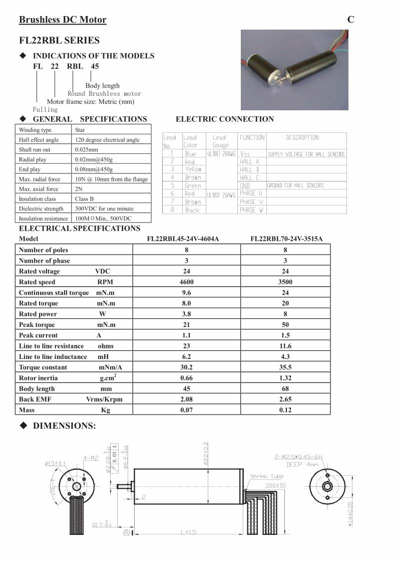
FL22RBL SERIES INDICATIONS OF THE MODELS
FL 22 RBL 45
Body lengthRound Brushless motor
Motor frame size: Metric (mm)Fulling
GENERAL SPECIFICATIONS ELECTRIC CONNECTION
ELECTRICAL SPECIFICATIONSModel FL22RBL45-24V-4604A FL22RBL70-24V-3515ANumber of poles 8 8Number of phase 3 3Rated voltage VDC 24 24Rated speed RPM 4600 3500Continuous stall torque mN.m 9.6 24Rated torque mN.m 8.0 20Rated power W 3.8 8Peak torque mN.m 21 50Peak current A 1.1 1.5Line to line resistance ohms 23 11.6Line to line inductance mH 6.2 4.3Torque constant mNm/A 30.2 35.5Rotor inertia g.cm2 0.66 1.32Body length mm 45 68Back EMF Vrms/Krpm 2.08 2.65Mass Kg 0.07 0.12
DIMENSIONS:
0.03
A
Winding type StarHall effect angle 120 degree electrical angleShaft run out 0.025mmRadial play 0.02mm@450gEnd play 0.08mm@450gMax. radial force 10N @ 10mm from the flangeMax. axial force 2NInsulation class Class BDielectric strength 500VDC for one minuteInsulation resistance 100MΩMin., 500VDC
Brushless DC Motor
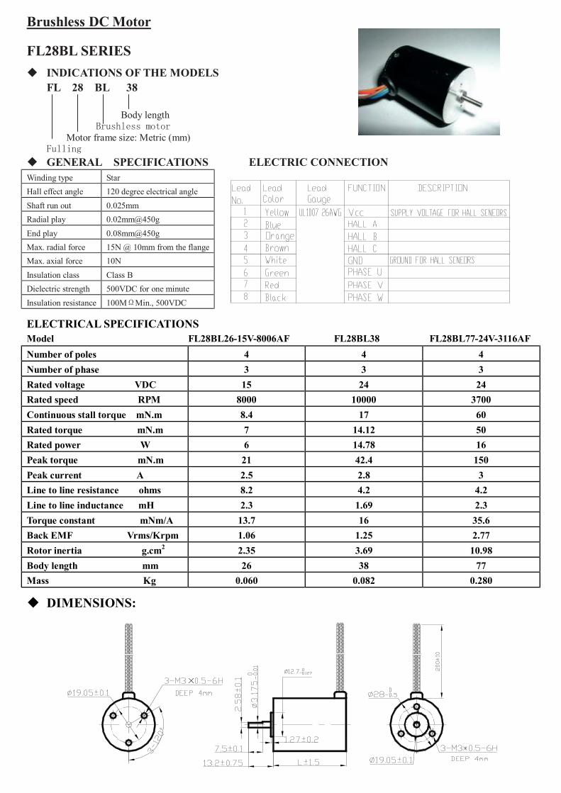
FL28BL SERIES INDICATIONS OF THE MODELS
FL 28 BL 38
Body lengthBrushless motor
Motor frame size: Metric (mm)Fulling
GENERAL SPECIFICATIONS ELECTRIC CONNECTION
ELECTRICAL SPECIFICATIONSModel FL28BL26-15V-8006AF FL28BL38 FL28BL77-24V-3116AFNumber of poles 4 4 4Number of phase 3 3 3Rated voltage VDC 15 24 24Rated speed RPM 8000 10000 3700Continuous stall torque mN.m 8.4 17 60Rated torque mN.m 7 14.12 50Rated power W 6 14.78 16Peak torque mN.m 21 42.4 150Peak current A 2.5 2.8 3Line to line resistance ohms 8.2 4.2 4.2Line to line inductance mH 2.3 1.69 2.3Torque constant mNm/A 13.7 16 35.6Back EMF Vrms/Krpm 1.06 1.25 2.77Rotor inertia g.cm2 2.35 3.69 10.98Body length mm 26 38 77Mass Kg 0.060 0.082 0.280
DIMENSIONS:
×
Winding type StarHall effect angle 120 degree electrical angleShaft run out 0.025mmRadial play 0.02mm@450gEnd play 0.08mm@450gMax. radial force 15N @ 10mm from the flangeMax. axial force 10NInsulation class Class BDielectric strength 500VDC for one minuteInsulation resistance 100MΩMin., 500VDC

Brushless DC Motor C2
FL33BL SERIES INDICATIONS OF THE MODELS
FL 33 BL 38
Body lengthBrushless motor
Motor frame size: Metric (mm)Fulling
GENERAL SPECIFICATIONS ELECTRIC CONNECTION
ELECTRICAL SPECIFICATIONSModel FL33BL38-24v-3007ANumber of poles 4Number of phase 3Rated voltage VDC 24Rated speed RPM 3000Continuous stall torque mN.m 26Rated torque mN.m 22Rated power W 7Peak torque mN.m 66Peak current A 2.1Line to line resistance ohms 12.8Line to line inductance mH 7Torque constant mNm/A 46.09Back EMF Vrms/Krpm 3.43Rotor inertia g.cm2 7.95
Body length mm 38Mass Kg 0.115
DIMENSIONS:
Winding type StarHall effect angle 120 degree electrical angleShaft run out 0.025mmRadial play 0.02mm@450gEnd play 0.08mm@450gMax. radial force 15N @ 10mm from the flangeMax. axial force 10NInsulation class Class BDielectric strength 500VDC for one minuteInsulation resistance 100MΩMin., 500VDC
Brushless DC Motor
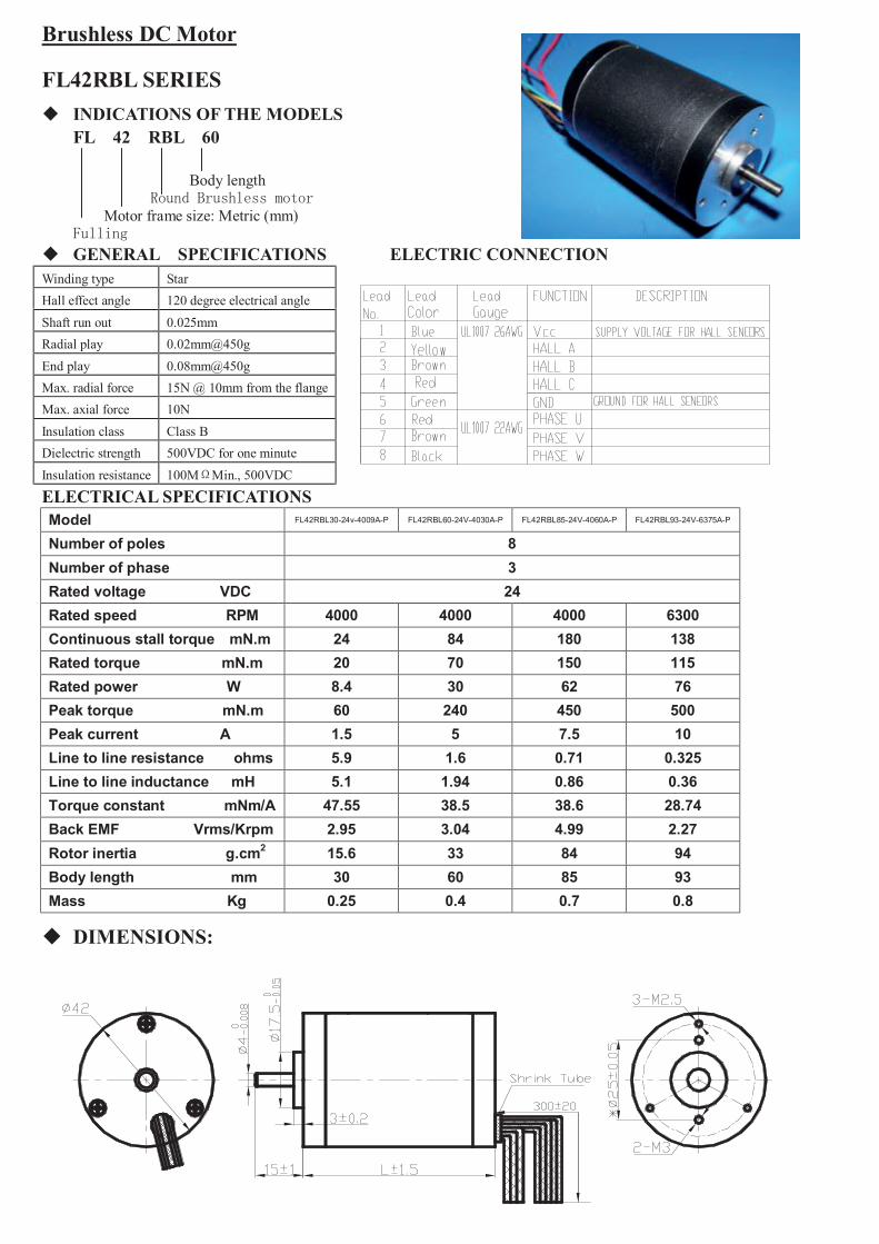
FL42RBL SERIES INDICATIONS OF THE MODELS
FL 42 RBL 60
Body lengthRound Brushless motor
Motor frame size: Metric (mm)Fulling
GENERAL SPECIFICATIONS ELECTRIC CONNECTION
ELECTRICAL SPECIFICATIONSModel FL42RBL30-24v-4009A-P FL42RBL60-24V-4030A-P FL42RBL85-24V-4060A-P FL42RBL93-24V-6375A-P
Number of poles 8Number of phase 3Rated voltage VDC 24Rated speed RPM 4000 4000 4000 6300Continuous stall torque mN.m 24 84 180 138Rated torque mN.m 20 70 150 115Rated power W 8.4 30 62 76Peak torque mN.m 60 240 450 500Peak current A 1.5 5 7.5 10Line to line resistance ohms 5.9 1.6 0.71 0.325Line to line inductance mH 5.1 1.94 0.86 0.36Torque constant mNm/A 47.55 38.5 38.6 28.74Back EMF Vrms/Krpm 2.95 3.04 4.99 2.27Rotor inertia g.cm2 15.6 33 84 94Body length mm 30 60 85 93Mass Kg 0.25 0.4 0.7 0.8
DIMENSIONS:
Winding type StarHall effect angle 120 degree electrical angleShaft run out 0.025mmRadial play 0.02mm@450gEnd play 0.08mm@450gMax. radial force 15N @ 10mm from the flangeMax. axial force 10NInsulation class Class BDielectric strength 500VDC for one minuteInsulation resistance 100MΩMin., 500VDC

Brushless DC Motor C3
FL42BLS SERIES INDICATIONS OF THE MODELS
FL 42 BLS 01
Series numberBrushless motor
Motor frame size: Metric (mm)Fulling
GENERAL SPECIFICATIONS ELECTRIC CONNECTION
Supply voltage for hall sensors
Ground for hall sensors
ELECTRICAL SPECIFICATIONSModel FL42BLS01 FL42BLS02 FL42BLS03 FL42BLS04Number of poles 8Number of phase 3Rated voltage VDC 24Rated speed RPM 4000Continuous stall torque N.m 0.075 0.15 0.22 0.3Rated torque N.m 0.0625 0.125 0.185 0.25Rated power W 26 52.5 77.5 105Peak torque N.m 0.19 0.38 0.56 0.75Peak current A 5.4 10.6 15.5 20Line to line resistance ohms 1.5 0.8 0.43 0.3Line to line inductance mH 2.1 1.2 0.71 0.5Torque constant Nm/A 0.035 0.0355 0.038 0.0355Back E.M.F Vrms/Krpm 2.45 2.71 2.74 2.62Rotor inertia g.cm2 24 48 72 96Body length mm 40.3 60.3 80.3 100.3Mass Kg 0.3 0.45 0.65 0.8
DIMENSIONS:
Winding type Delta
Hall effect angle 120 degree electrical angle
Shaft run out 0.025mm
Radial play 0.02mm@450g
End play 0.08mm@450g
Max. radial force 28N @ 20mm from the flange
Max. axial force 10N
Insulation class Class B
Dielectric strength 500VDC for one minute
Insulation resistance 100MΩMin., 500VDC

Brushless DC Motor
FL42BLSH SERIES INDICATIONS OF THE MODELS
FL 42 BLSH 01
Series numberBrushless motor with high torque
Motor frame size: Metric (mm)Fulling
GENERAL SPECIFICATIONS ELECTRIC CONNECTION
ELECTRICAL SPECIFICATIONSModel FL42BLSH01 FL42BLSH02 FL42BLSH03 FL42BLSH04Number of poles 10Number of phase 3Rated voltage VDC 24Rated speed RPM 3000Continuous stall torque N.m 0.084 0.19 0.31 0.43Rated torque N.m 0.07 0.16 0.26 0.36Rated power W 22 50 81 113Peak torque N.m 0.3 0.65 1.1 1.44Peak current A 6.2 11.8 16.8 25.6Resistance ohms 2.6 1.1 0.7 0.48Inductance mH 1.83 0.96 0.58 0.44Torque constant Nm/A 0.054 0.054 0.054 0.054Back E.M.F Vrms/Krpm 4.06 3.44 3.51 4.2Rotor inertia g.cm2 48 101 154 207Body length (L) mm 40.3 60.3 80.3 100.3Mass Kg 0.26 0.46 0.65 0.85
DIMENSIONS:
Winding type Delta
Hall effect angle 120 degree electrical angle
Shaft run out 0.025mm
Radial play 0.02mm@450g
End play 0.08mm@450g
Max. radial force 28N @ 20mm from the flange
Max. axial force 10N
Insulation class Class B
Dielectric strength 500VDC for one minute
Insulation resistance 100MΩMin., 500VDC
Brushless DC Motor C4
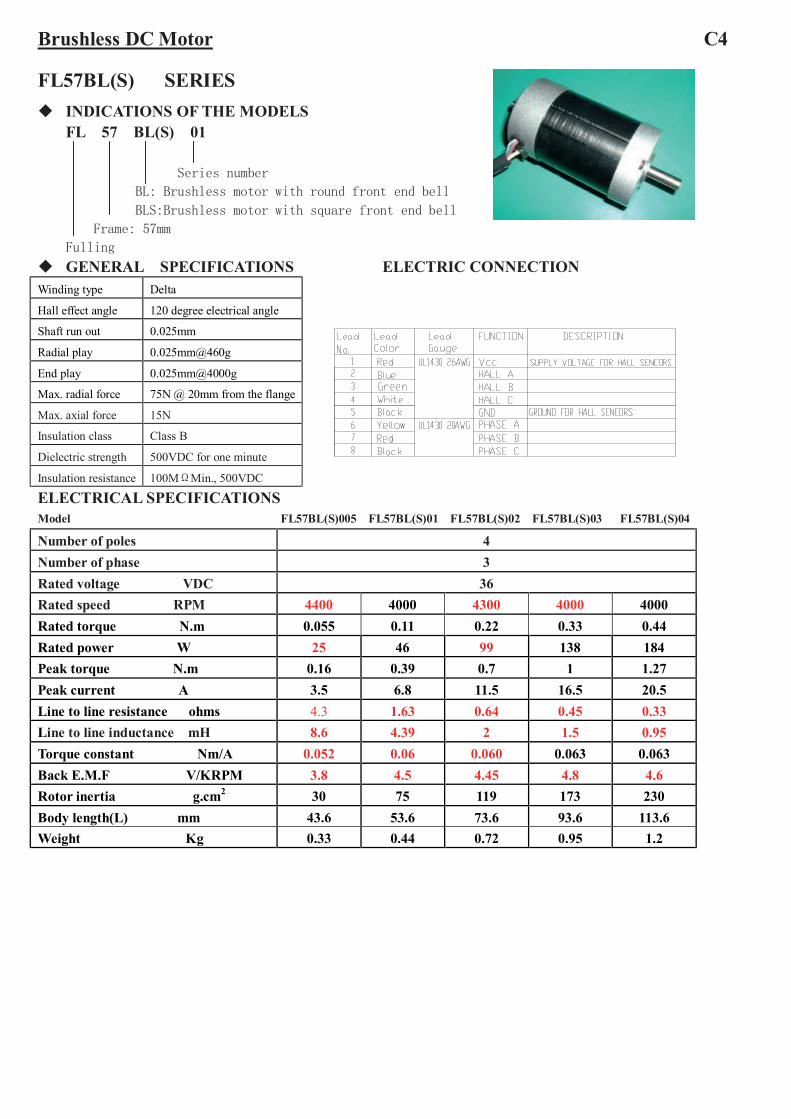
FL57BL(S) SERIES INDICATIONS OF THE MODELS
FL 57 BL(S) 01
Series number
BL: Brushless motor with round front end bell
BLS:Brushless motor with square front end bell
Frame: 57mm
Fulling
GENERAL SPECIFICATIONS ELECTRIC CONNECTION
ELECTRICAL SPECIFICATIONSModel FL57BL(S)005 FL57BL(S)01 FL57BL(S)02 FL57BL(S)03 FL57BL(S)04
Number of poles 4Number of phase 3Rated voltage VDC 36Rated speed RPM 4400 4000 4300 4000 4000Rated torque N.m 0.055 0.11 0.22 0.33 0.44Rated power W 25 46 99 138 184Peak torque N.m 0.16 0.39 0.7 1 1.27Peak current A 3.5 6.8 11.5 16.5 20.5Line to line resistance ohms 4.3 1.63 0.64 0.45 0.33Line to line inductance mH 8.6 4.39 2 1.5 0.95Torque constant Nm/A 0.052 0.06 0.060 0.063 0.063Back E.M.F V/KRPM 3.8 4.5 4.45 4.8 4.6Rotor inertia g.cm2 30 75 119 173 230Body length(L) mm 43.6 53.6 73.6 93.6 113.6Weight Kg 0.33 0.44 0.72 0.95 1.2
Winding type Delta
Hall effect angle 120 degree electrical angle
Shaft run out 0.025mm
Radial play 0.025mm@460g
End play 0.025mm@4000g
Max. radial force 75N @ 20mm from the flange
Max. axial force 15N
Insulation class Class B
Dielectric strength 500VDC for one minute
Insulation resistance 100MΩMin., 500VDC

Communcation Chart (CW Viewed From Front End Bell)
FL57BL(S)005/01/02/03 FL57BL(S)04
HA HB HC U V W
1 1 0 X L H
0 1 0 H L X
0 1 1 H X L
0 0 1 X H L
1 0 1 L H X
1 0 0 L X H
DIMENSIONS:
330±
30
BLKREDPHASE W
PHASE U
PHASE V
YELHA
HALL CONNECTING
HALL GND BLKHALL +5V RED
HCHB
BLU GRN WHT
THREE-PHASE CONNECTING
17±125±1
2±0.2
46±0.1
46±0.1
47.1±0.5X47.1±0.5
56.6±0.5X56.6±0.5
HA HB HC U V W
0 0 1 X H L
0 1 1 H X L
0 1 0 H L X
1 1 0 X L H
1 0 0 L X H
1 0 1 L H X

Brushless DC Motor C5
FL57BLSH SERIES INDICATIONS OF THE MODELS
FL 57 BLS H 01
Series number
High torque
Brushless motor
Frame
Fulling
GENERAL SPECIFICATIONS ELECTRIC CONNECTIONWinding type Star
Hall effect angle 120 degree electrical angle
Shaft run out 0.025mm
Radial play 0.025mm@460g
End play 0.025mm@4000g
Max. radial force 75N @ 20mm from the flange
Max. axial force 15N
Insulation class Class B
Dielectric strength 500VDC for one minute
Insulation resistance 100MΩMin., 500VDC
ELECTRICAL SPECIFICATIONSModel FL57BLSH01.001
Number of poles 4Number of phase 3Rated voltage VDC 24Rated speed RPM 2300Rated torque N.m 0.24Rated power W 58Peak torque N.m 0.55Peak current A 11.5Line to line resistance ohms 1.28Line to line inductance mH 1.56Torque constant Nm/A 0.0499Back E.M.F Vrms/Krpm 3.83Rotor inertia g.cm2 190Body length(L) mm 52Mass Kg 0.65
DIMENSIONS:
4-? 8.5

Brushless DC Motor
FL57HBL(S) SERIES INDICATIONS OF THE MODELS
FL 57 HBL(S) 01
Series Number
HBL: High torque,Brushless with round front end bell
HBLS:High torque,Brushless with square front end bell
Frame:57mm
Fulling
GENERAL SPECIFICATIONS ELECTRIC CONNECTION
LEADCOLORLEAD LEAD
GAUGEFUNCTION DESCRIPTION
RED
BLUE
GREEN
WHITE
BLACK
YELLOW
RED
BLACK
SUPPLY VOLTAGE FOR HALL SENSOR
GROUND FOR HALL SENSOR
ELECTRICAL SPECIFICATIONSMODEL FL57HBL(S)01 FL57HBL(S)02
Number of poles 8Number of phase 3Rated voltage VDC 36Rated speed RPM 4000Rated torque N.m 0.22 0.44Rated power W 92 184Peak torque N.m 0.6 1.2Peak current A 9 16Line to line resistance ohms 0.72 0.51Line to line inductance mH 0.97 0.59Torque constant Nm/A 0.065 0.061Back E.M.F V/KRPM 4.85 4.5Rotor inertia g.cm2 75 119Body length(L) mm 53.6 73.6Weight Kg 0.5 0.8
Winding type Y
Hall effect angle 120 degree electrical angleShaft run out 0.025mm
Radial play 0.025mm@460g
End play [email protected] force 75N @ 20mm from the flange
Max.axial force 15NInsulation class Class B
Dielectric strength 500VDC for one minute
Insulation resistance 100MΩ Min., 500VDC

Communcation Chart (CCW Viewed From Front End Bell)
2
DIMENSION:
330±30
BLKREDPHASE W
PHASE U
PHASE V
YELHA
HALL CONNECTING
HALL GND BLKHALL +5V RED
HCHB
BLU GRN WHT
THREE-PHASE CONNECTING
17±125±1
2±0.2
46±0.1
46±0.1
47.1±0.5X47.1±0.5
56.6±0.5X56.6±0.5
HA HB HC U V W
0 0 1 X H L
1 0 1 L H X
1 0 0 L X H
1 1 0 X L H
0 1 0 H L X
0 1 1 H X L

Brushless DC Motor C6FL86BLS SERIES INDICATIONS OF THE MODELS
FL 86 BLS 58
Body lengthBrushless motor
Motor frame size: Metric (mm)Fulling
GENERAL SPECIFICATIONS ELECTRIC CONNECTION COMMUTATION
ELECTRICAL SPECIFICATIONSModel FL86BLS58 FL86BLS71 FL86BLS98 FL86BLS125Number of poles 8Number of phase 3Rated voltage VDC 48Rated speed RPM 3000Rated torque N.m 0.35 0.7 1.4 2.1Rated power W 110 220 440 660Peak torque N.m 1.05 2.1 4.2 6.3Peak current A(ref) 11 20 37 56Line to line resistance ohms 0.098 0.39 0.21 0.14Line to line inductance mH 2.58 1.14 0.5 0.31Torque constant Nm/A 0.10 0.107 0.113 0.112Back E.M.F Vrms/KRPM 8.1 8.7 9.2 9.12Rotor inertia g.cm2 400 800 1600 2400Body length (L) mm 56 70 96 123Mass Kg 1.6 2.12 3.15 4.2 DIMENSIONS WIRE DIAGRAM
86±
1
8.4
1.52±0.2
31.75±1
86±1
0.2
69.5 0.2
Winding type StarHall effect angle 120 degree electrical angleShaft run out 0.038mmRadial play 0.025mm@5NEnd play 0.075mm@10NMax. radial force 200N @ 20mm from the flangeMax. axial force 65NInsulation class Class BDielectric strength 500VDC for one minuteInsulation resistance 100MΩMin., 500VDC
Brushless DC Motor C7
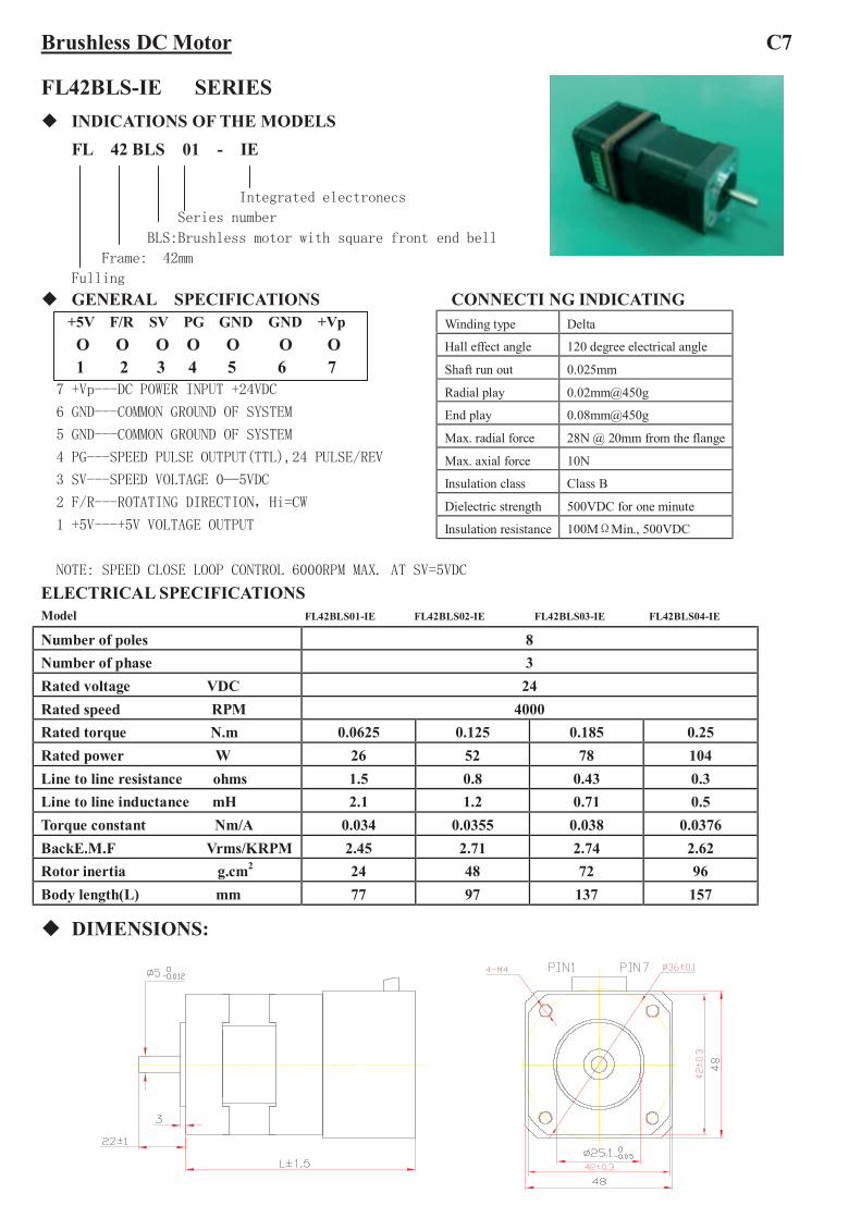
FL42BLS-IE SERIES INDICATIONS OF THE MODELS
FL 42 BLS 01 - IE
Integrated electronecs
Series number
BLS:Brushless motor with square front end bell
Frame: 42mm
Fulling
GENERAL SPECIFICATIONS CONNECTI NG INDICATING+5V F/R SV PG GND GND +VpO O O O O O O1 2 3 4 5 6 7
7 +Vp---DC POWER INPUT +24VDC
6 GND---COMMON GROUND OF SYSTEM
5 GND---COMMON GROUND OF SYSTEM
4 PG---SPEED PULSE OUTPUT(TTL),24 PULSE/REV
3 SV---SPEED VOLTAGE 0—5VDC
2 F/R---ROTATING DIRECTION,Hi=CW
1 +5V---+5V VOLTAGE OUTPUT
NOTE: SPEED CLOSE LOOP CONTROL 6000RPM MAX. AT SV=5VDC
ELECTRICAL SPECIFICATIONSModel FL42BLS01-IE FL42BLS02-IE FL42BLS03-IE FL42BLS04-IE
Number of poles 8Number of phase 3Rated voltage VDC 24Rated speed RPM 4000Rated torque N.m 0.0625 0.125 0.185 0.25Rated power W 26 52 78 104Line to line resistance ohms 1.5 0.8 0.43 0.3Line to line inductance mH 2.1 1.2 0.71 0.5Torque constant Nm/A 0.034 0.0355 0.038 0.0376BackE.M.F Vrms/KRPM 2.45 2.71 2.74 2.62Rotor inertia g.cm2 24 48 72 96Body length(L) mm 77 97 137 157
DIMENSIONS:
Winding type Delta
Hall effect angle 120 degree electrical angle
Shaft run out 0.025mm
Radial play 0.02mm@450g
End play 0.08mm@450g
Max. radial force 28N @ 20mm from the flange
Max. axial force 10N
Insulation class Class B
Dielectric strength 500VDC for one minute
Insulation resistance 100MΩMin., 500VDC

Brushless DC Motor C8
FL57BL(S)-IE SERIES INDICATIONS OF THE MODELS
FL 57 BL(S) 01 - IEIntegrated driver
Series number
BL: Brushless motor with round front end bell
BLS:Brushless motor with square front end bell
Frame: 57mm
Fulling
GENERAL SPECIFICATIONS CONNECTI NG INDICATING+Vp GND GND PG SV F/R +5VO O O O O O O1 2 3 4 5 6 7
7 +Vp---DC POWER INPUT +36VDC
6 GND---COMMON GROUND OF SYSTEM
5 GND---COMMON GROUND OF SYSTEM
4 PG---SPEED PULSE OUTPUT(TTL),12 PULSE/REV
3 SV---SPEED VOLTAGE 0—5VDC
2 F/R---ROTATING DIRECTION
1 +5V---+5V VOLTAGE OUTPUT
ELECTRICAL SPECIFICATIONSModel FL57BL(S)005 FL57BL(S)01 FL57BL(S)02 FL57BL(S)03 FL57BL(S)04
Number of poles 4Number of phase 3Rated voltage VDC 36Rated speed RPM 4400 4000 4300 4000 4000Rated torque N.m 0.055 0.11 0.22 0.33 0.44Rated power W 25 46 99 138 184Peak torque N.m 0.16 0.39 0.7 1 1.27Peak current A 3.5 6.8 11.5 16.5 20.5Line to line resistance ohms 4.3 1.63 0.64 0.45 0.33Line to line inductance mH 8.6 4.39 2 1.5 0.95Torque constant Nm/A 0.052 0.06 0.060 0.063 0.063Back E.M.F V/KRPM 3.8 4.5 4.45 4.8 4.6Rotor inertia g.cm2 30 75 119 173 230Body length(L0 mm 90 100 139 159 179
Weight Kg 0.56 0.67 0.9 1.2 1.46
Winding type Delta
Hall effect angle 120 degree electrical angle
Shaft run out 0.025mm
Radial play 0.025mm@460g
End play 0.025mm@4000g
Max. radial force 75N @ 20mm from the flange
Max. axial force 15N
Insulation class Class B
Dielectric strength 500VDC for one minute
Insulation resistance 100MΩMin., 500VDC

Communcation Chart (CW Viewed From Front End Bell)
FL57BL(S)005/01/02/03 FL57BL(S)04
HA HB HC U V W
1 1 0 X L H
0 1 0 H L X
0 1 1 H X L
0 0 1 X H L
1 0 1 L H X
1 0 0 L X H
DIMENSIONS:
60±1
56.6±0.5X56.6±0.5
47.1±0.5X47.1±0.5
FL57BLSxx-IE
FL57BLxx-IE
25±1
2±0.2
1.6±0.2
PHASE W
PHASE U
PHASE V
HA
HALL CONNECTING
HALL GND HALL +5V
HCHB
THREE-PHASE CONNECTING
60±1
60±1
60±120.6±1
HA HB HC U V W
0 0 1 X H L
0 1 1 H X L
0 1 0 H L X
1 1 0 X L H
1 0 0 L X H
1 0 1 L H X

FL28BL38 - 24XX - 28JX Gearbox Brushless MotorINDICATION OF GEARBOX BRUSHLESS MOTOR
Motor SpecificationsMotor Name FL28BL38-2430 FL28BL38-2440Number of poles 4 4Number of phase 3 3Rated Voltage VDC 24 24Rated Speed RPM 2000 2700Rated Torque mN.m 5 7Rated Power W 1.0 1.9Rated Current A 0.15 0.20Peak Current A 0.45 0.60Line to line Resistance Ohms 93.3 55Line to line Inductance mH 28 18.3
Gearbox SpecificationsReduction Ratio 3.7 5.2 14 19 27 51 71 100 139 264Number of Gear Trains 1 1 2 2 2 3 3 3 3 4Length of Gear Box 31.5 31.5 40.0 40.0 40.0 48.5 48.5 48.5 48.5 57.5Max.Permissible load in a short time
Kg.cm5 5 10 10 10 30 30 30 30 30
FL28BL38-2430-28JX20KNo-load Speed RPM 810 577 214 158 111 59 42 30 21 11Rated Speed RPM 540 384 142 105 74 39 28 20 14 7Rated Torque mN.m 16.7 23.4 56.7 77 109 186 259 365 507 866
FL28BL38-2440-28JX20KNo-load Speed RPM 1081 769 285 210 148 78 56 40 28 15Rated Speed RPM 729 519 192 192 100 52 38 27 19 10Rated Torque mN.m 23.3 32.7 79.4 107 153 260 362 510 709 1347
Dimensions
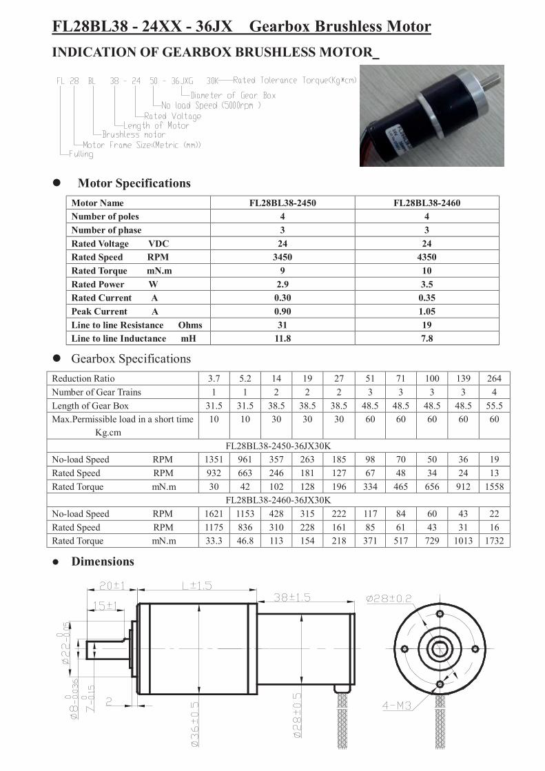
FL28BL38 - 24XX - 36JX Gearbox Brushless MotorINDICATION OF GEARBOX BRUSHLESS MOTOR
Motor SpecificationsMotor Name FL28BL38-2450 FL28BL38-2460Number of poles 4 4Number of phase 3 3Rated Voltage VDC 24 24Rated Speed RPM 3450 4350Rated Torque mN.m 9 10Rated Power W 2.9 3.5Rated Current A 0.30 0.35Peak Current A 0.90 1.05Line to line Resistance Ohms 31 19Line to line Inductance mH 11.8 7.8
Gearbox SpecificationsReduction Ratio 3.7 5.2 14 19 27 51 71 100 139 264Number of Gear Trains 1 1 2 2 2 3 3 3 3 4Length of Gear Box 31.5 31.5 38.5 38.5 38.5 48.5 48.5 48.5 48.5 55.5Max.Permissible load in a short time
Kg.cm10 10 30 30 30 60 60 60 60 60
FL28BL38-2450-36JX30KNo-load Speed RPM 1351 961 357 263 185 98 70 50 36 19Rated Speed RPM 932 663 246 181 127 67 48 34 24 13Rated Torque mN.m 30 42 102 128 196 334 465 656 912 1558
FL28BL38-2460-36JX30KNo-load Speed RPM 1621 1153 428 315 222 117 84 60 43 22Rated Speed RPM 1175 836 310 228 161 85 61 43 31 16Rated Torque mN.m 33.3 46.8 113 154 218 371 517 729 1013 1732
Dimensions

FL42RBL60-2440-48JXG50K Gearbox Brushless MotorINDICATION OF GEARBOX BRUSHLESS MOTOR
Motor SpecificationsMotor Name FL42RBL60-2440-48JXG50KNumber of poles 8Number of phase 3Rated Voltage VDC 24Rated Speed RPM 2800Rated Torque N.m 0.07Rated Power W 20.5Rated Current A 1.4Peak Current A 4.2Line to line Resistance Ohms 2.98Line to line Inductance mH 3.50
Gearbox SpecificationsReduction Ratio 15 19 24 56 71 91 116Number of Gear Trains 2 2 2 3 3 3 3Length of Gear Box 42.5 42.5 42.5 52.5 52.5 52.5 52.5Max.Permissible load in a short time
Kg.cm60 60 60 150 150 150 150
No-load Speed RPM 266 210 166 71 56 44 34Rated Speed RPM 186 147 116 50 39 30 24Rated Torque N.m 0.85 1.08 1.36 2.86 3.63 4.65 5.92
Dimensions

FL42RBL60-24XX-40JXG50K Gearbox Brushless MotorINDICATION OF GEARBOX BRUSHLESS MOTOR
Motor SpecificationsMotor Name FL42RBL60-2420-40JXG50K FL42RBL60-2430-40JXG50KNumber of poles 8 8Number of phase 3 3Rated Voltage VDC 24 24Rated Speed RPM 1400 2100Rated Torque N.m 0.04 0.05Rated Power W 5.8 11.0Rated Current A 0.5 0.85Peak Current A 1.5 2.6Line to line Resistance Ohms 11.9 6.0Line to line Inductance mH 15.0 6.4
Gearbox SpecificationsReduction Ratio 3.6 4.9 15 19 24 56 71 91 116 212Number of Gear Trains 1 1 2 2 2 3 3 3 3 4Length of Gear Box 35.5 35.5 45.5 45.5 45.5 55.5 55.5 55.5 55.5 66Max.Permissible load in a short time
Kg.cm15 15 60 60 60 150 150 150 150 150
FL42RBL60-2420-40JXG50KNo-load Speed RPM 555 408 133 105 83 35 28 22 17 9Rated Speed RPM 388 285 93 73 58 25 19 15 12 6.6Rated Torque N.m 0.13 0.18 0.49 0.62 0.776 1.63 2.07 2.65 3.38 5.56
FL42RBL60-2430-40JXG50KNo-load Speed RPM 833 612 200 157 125 53 42 33 25 14Rated Speed RPM 583 428 140 110 87 375 29 23 18 9.9Rated Torque N.m 0.16 0.19 0.60 0.76 0.97 2.04 2.58 3.31 4.22 6.95
Dimensions
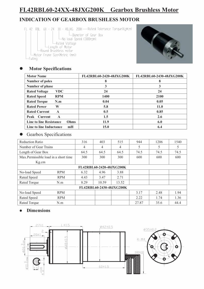
FL42RBL60-24XX-48JXG200K Gearbox Brushless MotorINDICATION OF GEARBOX BRUSHLESS MOTOR
Motor SpecificationsMotor Name FL42RBL60-2420-48JXG200K FL42RBL60-2430-48JXG200KNumber of poles 8 8Number of phase 3 3Rated Voltage VDC 24 24Rated Speed RPM 1400 2100Rated Torque N.m 0.04 0.05Rated Power W 5.8 11.0Rated Current A 0.5 0.85Peak Current A 1.5 2.6Line to line Resistance Ohms 11.9 6.0Line to line Inductance mH 15.0 6.4
Gearbox SpecificationsReduction Ratio 316 403 515 944 1206 1540Number of Gear Trains 4 4 4 5 5 5Length of Gear Box 64.5 64.5 64.5 74.5 74.5 74.5Max.Permissible load in a short time
Kg.cm300 300 300 600 600 600
FL42RBL60-2420-48JXG200KNo-load Speed RPM 6.32 4.96 3.88Rated Speed RPM 4.43 3.47 2.71Rated Torque N.m 8.29 10.59 13.52
FL42RBL60-2430-48JXG200KNo-load Speed RPM 3.17 2.48 1.94Rated Speed RPM 2.22 1.74 1.36Rated Torque N.m 27.87 35.6 44.4
Dimensions

FL57BLxx –36V -56JX300K Brushless DC Planetary Gear MotorINDICATION OF Brushless DC Planetary Gear Motor
Motor SpecificationsModel FL57BL01-36V FL57BL02-36V FL57BL03-36V FL57BL04-36V
Number of poles 4Number of phase 3Rated voltage VDC 36Rated speed RPM 4000 4300 4000 4000Rated torque N.m 0.11 0.22 0.33 0.44Rated power W 46 99 138 184Line to line resistance ohms 1.63 0.64 0.45 0.33Line to line inductance mH 4.39 2 1.5 0.95Torque constant Nm/A 0.06 0.06 0.063 0.063Back E.M.F Vrms/KRPM 4.5 4.45 4.8 4.6Rotor inertia g.cm2 75 119 173 230Motor body length(L1) mm 57.4 77.4 97.4 117.4
Gearbox SpecificationsReduction Ratio 3.6 4.25 13 15 18 47 55 65 76 168 198 234 276 326
Number of Gear Trains 1 2 3 4Length of Gear Box(L2) mm 52.6 52.6(61) 64.2(72) 75.7(83.7)Rated torque(N.m) 1.5 5 10 15(30)Max.Permissible load in a short time N。m 4.5 15 30 45(90)MODEL FL57BL01-36V-56JX300KRated Torque N.m 0.36 0.42 1.15 1.34 1.6 3.8 4.4 5.2 6 12 14.2 16.9 20 23.5
Rated Speed RPM 1111 941 308 267 222 85 73 62 53 24 20 17 14 12
Weight Kg 1.1 1.185 1.362 1.538(1.717)
MODEL FL57BL02-36V-56JX300KRated Torque N.m 0.72 0.84 2.3 2.68 3.2 7.6 8.8 10.4 12 24 28.4
Rated Speed RPM 1194 1011 330 286 238 91 78 66 56 25. 22
Weight Kg 1.38 1.465 1.642 1.8(1.99)
MODEL FL57BL03-36V-56JX300KRated Torque N.m 1 1.22 3.47 4 4.7 11 13.2 15.6 18.2
Rated Speed RPM 1111 941 308 267 222 85 73 62 53
Weight Kg 1.61 1.695 1.872 2(2.22)
MODEL FL57BL04-36V-56JX300KRated Torque N.m 1.42 1.68 4.6 5.36 6.4 15.2 17.6 20.8 24
Rated Speed RPM 1111 941 308 267 222 85 73 62 53
Weight Kg 1.86 1.945 2.1 2.3(2.5)
Dimensions

28±1
18±0.5
330±30

FL57BL-JB Gearbox Brushless Motor C13 Motor Specifications
Same as FL57BL(S) series motor
Gearbox SpecificationsRatio 3 7.5 12.5 15 25 30 50 75 90 100 120 150Number of gear trains 2 2 2 3 3 3 4 4 5 5 5 5Length(L) mm 32 32 32 32 40 40 40 40 40 40 40 40Peak torque kg.cm 50AverageBacklashAtNolaod 4 deg. 3.5 deg. 3 deg. 2.5deg
Model FL57BL01-JBXXRated Speed Rpm 1333 533 320 266 160 133 80 53Rated Torque N。m 0.27 0.67 1.1 1.2 2.0 2.4 3.6 5.4
Weight Kg 1.39 1.49Model FL57BL02-JBXXRatedSpeed Rpm 1433 573 344 286 172 143Rated Torque N。m 0.53 1.33 2.22 2.4 4 4.8
Weight Kg 1.67 1.77Model FL57BL03-JBXXRatedSpeed Rpm 1333 533 320 266 160RatedTorque N。m 0.8 2.0 3.34 3.6 6.0Weight Kg 1.9 2Model FL57BL04-JBXXRatedSpeed Rpm 1333 533 320 266RatedTorque N。m 1.0 2.67 4.45 4.8
Weight Kg 2.15
Dimensions
46±0.1
300±
30
10±
0.25
60±
1
60±1
L1 is same as FL57Blseries , be 53.6mm, 73.6mm, 93.6mm, 113.6mm.

FL86BLS-90JB SPUR GEARBOX BLDC MOTOR INDICATIONS OF THE MODELS
FL 86 BLS 58 - 90 JB 30
Ratio: 1:30 Spur gearbox
Gearbox frame: 90mm*90mmMotor model: same specs with FL86BLS series motor
Gearbox SpecificationsRatio 3 5 6 7.5 9 10 12.5 15 18 20 25 30 36 40 50 60 75 90 100 120
Weight 1.3kg 1.5kg
Number of gear trains 2 3 4
Nominal torque 30N.m
Ultimate torque 45N.m
Efficiency 81% 73% 66%
Backlash 4 deg 3.5deg 2.5deg
Gear Motor SpecificationsRatio 3 5 6 7.5 9 10 12.5 15 18 20 25 30 36 40 50 60 75 90 100 120
Rated torque(N.m) 0.85 1.42 1.70 2.13 2.55 2.84 3.54 4.25 4.60 5.11 6.38 7.67 9.20 9.24 11.6 13.8 17.3 20.8 23.1 27.7
Rated speed(RPM) 1000 600 500 400 333 300 240 200 167 150 120 100 83.3 75 60 50 40 33.3 30 25
FL86BLS58-90JB
Ultimate torque(N.m) 2.55 4.25 5.10 6.38 7.65 8.52 10.6 12.7 13.8 15.3 19.1 23 27.6 27.7 34.8 41.4 45
Rated torque(N.m) 1.70 2.84 3.4 4.25 5.10 5.67 7.08 8.50 9.20 10.2 12.8 15.3 18.4 18.5 23.1 27.7 --- --- --- ---
Rated speed(RPM) 1000 600 500 400 333 300 240 200 167 150 120 100 83.3 75 60 50 --- --- --- ---
FL86BLS71-90JB
Ultimate torque(N.m) 5.1 8.52 10.2 12.7 15.3 17.0 21.2 25.5 27.6 30.6 38.4 45 --- --- --- ---
Rated torque(N.m) 3.4 5.67 6.80 8.50 10.2 11.3 14.2 17 18.4 20.4 25.5 30.6 --- --- --- --- --- --- --- ---
Rated speed(RPM) 1000 600 500 400 333 300 240 200 167 150 120 100 --- --- --- --- --- --- --- ---
FL86BLS98-90JB
Ultimate torque(N.m) 10.2 17.0 20.4 25.5 30.6 33.9 42.6 45 --- --- --- --- --- --- --- ---
Rated torque(N.m) 5.1 8.5 10.2 12.7 15.3 17.0 21.2 25.5 27.5 30.6 --- --- --- --- --- --- --- --- --- ---
Rated speed(RPM) 1000 600 500 400 333 300 240 200 167 150 --- --- --- --- --- --- --- --- --- ---
FL86BLS125-90JB
Ultimate torque(N.m) 15.3 25.5 30.6 38.1 45 --- --- --- --- --- --- --- --- --- ---
DIMENSIONS WIRE DIAGRAM
L2(mm)RATIO
FL86BLS58-90JB FL86BLS71-90JB FL86BLS98-90JB FL86BLS125-90JB
L1(mm)
3---15 42
18---120
72 86 112 139
60

FL86BLS-90NN PLANETARY GEARBOX BLDC MOTOR INDICATIONS OF THE MODELS
FL 86 BLS 58 - 90 NN 30
Ratio: 1:30 Planetary gearbox
Gearbox frame: 90mm*90mmMotor model: same specs with FL86BLS series motor
Gearbox SpecificationsRatio 3 5 7 9 10 15 20 30 40 60 80 100 150 200 225
Nominal torque(N.m) 55 60 70 90 100 120 180
Ultimate torque(N.m) 85 90 105 135 150 180 250
Max. radial force for 2000h(N) 910
Max. axial force for 2000h(N) 580
Backlash(Standard/Precision)
(Arcmin)
<30/10
Torsional rigidity(N.m/Arcmin) 5
Max. input speed(RPM) 4,500
Advised input speed(RPM) 2,500
Running Noise(dB) 66
Efficiency at full load >90%
Average lifetime(hours) >20,000
Weight(kg) 2.8
Direction of rotation Contrary with input
Degree of protection IP55
Gear Motor SpecificationsRatio 3 5 7 9 10 15 20 30 40 60 80 100 150 200 225
Rated torque(N.m) 0.95 1.58 2.20 2.84 3.15 4.72 6.3 9.45 12.6 18.9 25.2 31.5 52.5 63 70.8
Rated speed(RPM) 1,000 600 428.6 333.3 300 200 150 100 75 50 37.5 30 20 15 13.3
FL86BLS58-90JB
Ultimate torque(N.m) 2.85 4.74 6.6 8.52 9.45 14.2 21 28.4 37.8 56.7 75.6 94.5 157.5 180 212.4
Rated torque(N.m) 1.9 3.16 4.4 5.68 6.3 9.44 12.6 18.9 25.2 37.8 50.4 63 105 126 141.6
Rated speed(RPM) 1,000 600 428.6 333.3 300 200 150 100 75 50 37.5 30 20 15 13.3
FL86BLS71-90JB
Ultimate torque(N.m) 5.7 9.48 13.2 17.04 18.9 28.32 37.8 56.7 75.6 113.4 150 180 250
Rated torque(N.m) 3.8 6.32 8.8 11.36 12.6 18.88 25.2 37.8 50.4 75.6 100.8 126 --- --- ---
Rated speed(RPM) 1,000 600 428.6 333.3 300 200 150 100 75 50 37.5 30 --- --- ---
FL86BLS98-90JB
Ultimate torque(N.m) 11.4 18.96 26.4 34 37.8 56.6 75.6 113.4 150 180 --- --- ---
Rated torque(N.m) 5.7 9.48 13.2 17 18.9 28.3 37.8 56.7 75.6 --- --- --- --- --- ---
Rated speed(RPM) 1,000 600 428.6 333.3 300 200 150 100 75 --- --- --- --- --- ---
FL86BLS125-90JB
Ultimate torque(N.m) 17.1 28.4 39.6 51 56.7 84.9 113.4 135 150 --- --- --- --- --- ---
DIMENSIONS WIRE DIAGRAM
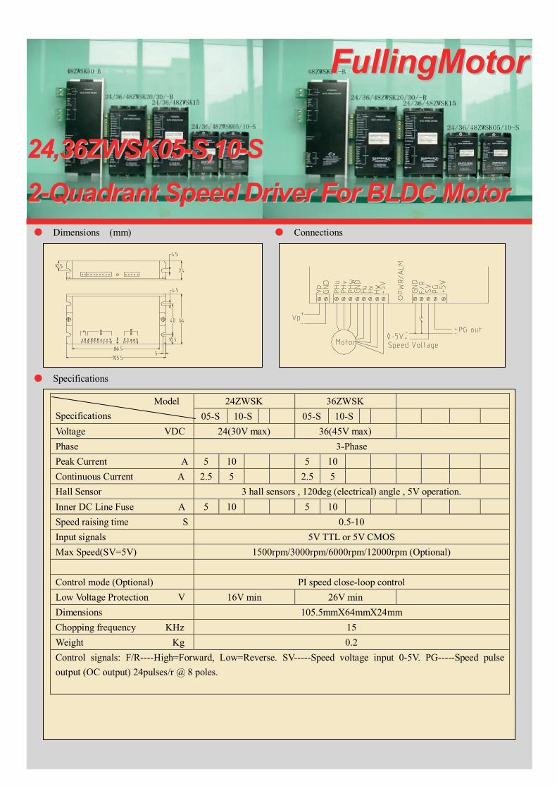
● Dimensions (mm) ● Connections
● Specifications
FFuulllliinnggMMoottoorr
2244,,3366ZZWWSSKK0055--SS,,1100--SS22--QQuuaaddrraanntt SSppeeeedd DDrriivveerr FFoorr BBLLDDCC MMoottoorr
24ZWSK 36ZWSKModelSpecifications 05-S 10-S 05-S 10-SVoltage VDC 24(30V max) 36(45V max)Phase 3-PhasePeak Current A 5 10 5 10Continuous Current A 2.5 5 2.5 5Hall Sensor 3 hall sensors , 120deg (electrical) angle , 5V operation.Inner DC Line Fuse A 5 10 5 10Speed raising time S 0.5-10Input signals 5V TTL or 5V CMOSMax Speed(SV=5V) 1500rpm/3000rpm/6000rpm/12000rpm (Optional)
Control mode (Optional) PI speed close-loop controlLow Voltage Protection V 16V min 26V minDimensions 105.5mmX64mmX24mmChopping frequency KHz 15Weight Kg 0.2Control signals: F/R----High=Forward, Low=Reverse. SV-----Speed voltage input 0-5V. PG-----Speed pulseoutput (OC output) 24pulses/r @ 8 poles.

● Dimensions (mm) ● Connections
● Specifications
FFuulllliinnggMMoottoorr
2244,,3366,,4488ZZWWSSKK115522--QQuuaaddrraanntt SSppeeeedd DDrriivveerr FFoorr BBLLDDCC MMoottoorr
ModelSpecifications
24ZWSK15 36ZWSK15 48ZWSK15
Voltage VDC 24(30V max) 36(45V max) 48(56V max)Phase 3-PhasePeak Current A 15 15 15Continuous Current A 7.5 7.5 7.5Hall Sensor 3 hall sensors , 120deg (electrical) angle , 6.25V operation.Inner DC Line Fuse A 15 15 15Speed raising time S 0.5-10Input signals 5V TTL or CMOS (6.25V max)Max Speed(SV=4V,SV gain=1) 1500rpm/3000rpm/6000rpm/12000rpm (Optional)Speed Voltage (SV) gain 0-1.0 (Gain=1 @SV ADJ on the Right)Control mode PI speed close-loop controlLow Voltage Protection V 16V min 26V min 36V minDimensions 161.5mmX81.2mmX31mmChopping frequency KHz 15Weight Kg 0.30Control signals: F/R----High=Forward, Low=Reverse. EN-----High=Disable, Low=Enable. BK-----Low=Motorbrake, High=Operating. SV-----Speed voltage input 0-5V. PG-----Speed pulse output (OC output) 24pulses/r @ 8poles. ALM-------Alarm output (OC output),Low=Alarm.

● Dimensions (mm) ● Connections
● Specifications
FFuulllliinnggMMoottoorr
2244,,3366,,4488ZZWWSSKK2200--BB,,3300--BB22--QQuuaaddrraanntt SSppeeeedd DDrriivveerr FFoorr BBLLDDCC MMoottoorr
24ZWSK 36ZWSK 48ZWSKModelSpecifications 20-B 30-B 20-B 30-B 20-B 30-BVoltage VDC 24(30V max) 36 (45V max) 48(56V max)Phase 3-PhasePeak Current A 20 30 20 30 20 30Continuous Current A 10 15 10 15 10 15Hall Sensor 3 hall sensors , 120deg (electrical) angle , 6.25V operation.
Speed raising time S 0.5-10Input signals 5V TTL or CMOS (6.25V max)Max Speed(SV=4.5V,SV gain=1) 1500rpm/3000rpm/6000rpm/12000rpm (Optional)Speed Voltage (SV) gain 0-1.0 (Gain=1 @SV ADJ on the Right)Control mode PI speed close-loop controlLow Voltage Protection V 16V min 26V min 36V minDimensions 161.5mmX82mmX45mmChopping frequency KHz 15Weight Kg 0.4Control signals: F/R----High=Forward, Low=Reverse. EN-----High=Disable, Low=Enable. BK-----Low=Motorbrake, High=Operating. SV-----Speed voltage input 0-5V. PG-----Speed pulse output (OC output) 24pulses/r @ 8poles. ALM-------Alarm output (OC output),Low=Alarm.
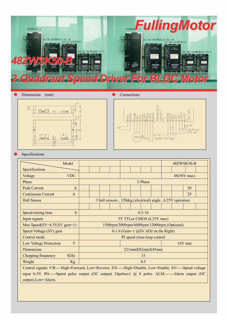
● Dimensions (mm) ● Connections
● Specifications
FFuulllliinnggMMoottoorr
4488ZZWWSSKK5500--BB22--QQuuaaddrraanntt SSppeeeedd DDrriivveerr FFoorr BBLLDDCC MMoottoorr
48ZWSK50-BModelSpecificationsVoltage VDC 48(56V max)Phase 3-PhasePeak Current A 50Continuous Current A 25Hall Sensor 3 hall sensors , 120deg (electrical) angle , 6.25V operation.
Speed raising time S 0.5-10Input signals 5V TTLor CMOS (6.25V max)Max Speed(SV=4.5V,SV gain=1) 1500rpm/3000rpm/6000rpm/12000rpm (Optional)Speed Voltage (SV) gain 0-1.0 (Gain=1 @SV ADJ on the Right)Control mode PI speed close-loop controlLow Voltage Protection V 16V minDimensions 221mmX82mmX45mmChopping frequency KHz 15Weight Kg 0.5Control signals: F/R----High=Forward, Low=Reverse. EN-----High=Disable, Low=Enable. SV-----Speed voltageinput 0-5V. PG-----Speed pulse output (OC output) 24pulses/r @ 8 poles. ALM-------Alarm output (OCoutput),Low=Alarm.


