systimax application assurance design guide - commscope · systimax® application assurance design...
TRANSCRIPT
SYSTIMAX® Application Assurance design guide
Application guide

commscope.com 2
ContentsExecutive summary 3
Fiber infrastructure challenges 4
Table 1. Some Ethernet and Fibre Channel applications showing loss budget and reach ............4
Designing the fiber-optic physical network 5
Optical application support 5
Table 2. IEEE Ethernet Standards .............................................................................................................6
CommScope performance specifications 8
Table 3. 8G Fibre Channel FC-PI-4 800-MX-SN supported distances with low-loss connections .........................................................................................................................8Table 4. 8G Fibre Channel FC-PI-4 800-MX-SN supported distances with ultra-low-loss connections ...............................................................................................................9Table 5. 32 Gigabit Fibre Channel, 850 nm Serial (3200-M5x-SN) with ULL connections ................................................................................................................................. 9Table 6. 40 Gigabit Ethernet, 850 nm SWDM (40G-SWDM4) supported distances ................. 10
Performance delivered 10
Figure 1. Fiber Performance Calculator ............................................................................................... 11
Conclusion 12
Appendix 1: Partial list of application tables 13
Table A-1. 40 gigabit Ethernet, 850 nm parallel (40GBASE-SR4) LL connections .......................................................................................................................................... 13Table A-2. 40 gigabit Ethernet, 850 nm 4-lane parallel (40GBASE-SR4) ULL connections ....................................................................................................................................... 13Table A-3. 40 gigabit Ethernet, FIT extended reach 850 nm (40GBASE–eSR4) ULL connections ....................................................................................................................................... 13Table A-4. 40 gigabit Ethernet, Cisco “BiDi” (QSFP-40G-SR-BD) LL connections .......................................................................................................................................... 14Table A-5. 40 gigabit Ethernet, Cisco “BiDi” (QSFP-40G-SR-BD) ULL connections ....................................................................................................................................... 14Table A-6. 100 gigabit Ethernet, 850 nm four-lane parallel (100GBASE-SR4) LL connections .......................................................................................................................................... 14Table A-7. 100 gigabit Ethernet, 850 nm four-lane parallel (100GBASE-SR4) ULL connections ....................................................................................................................................... 15Table A-8. 100 gigabit Ethernet, 850 nm SWDM (100G-SWDM4) ULL connections ....................................................................................................................................... 15
commscope.com 3
Executive summaryEmbracing the digitization of the enterprise is a competitive imperative. Data centers serve a pivotal role in this journey. Modern applications are evolving quickly to take advantage of a wide array of services and new technologies that promise quicker time to value for new applications, and scale and scope to serve your customers whenever and wherever they connect with your business. This requires a new approach to data centers as it becomes clear that the strategies and architectures that got us to where we are will not get us to where we need to go in the future. The incredible pace of technological change, insatiable demand for bandwidth, changing CapEx vs OpEx models, and public vs private clouds will all blend together in proportion to your business’s unique requirements. New design tools are required to speed the design and planning phase—and to keep pace with the capacity and performance demands while delivering optimal infrastructure ROI.
To address these challenges, CommScope offers a suite of tools that simplify the design, deployment and ongoing expansion to support the high speed migration of fiber connectivity within data centers. For example, the SYSTIMAX® Performance Specifications define channel topology limits specific to SYSTIMAX cabling solutions for a wide range of applications, including standards-based, multisource agreements (MSAs) and proprietary specifications. Additionally, the SYSTIMAX Fiber Performance Calculator provides the attenuation requirements for a proposed cabling channel while simultaneously determining which applications the channel will support. CommScope stands behind the Performance Specification and the Fiber Performance Calculator analysis with warranty* assurance for all the supported applications. Not only do these tools allow rapid design exploration, they form the basis of our unique SYSTIMAX Application Assurance. Under the terms of CommScope’s 25 Year Extended Product Warranty and Application Assurance (“System Warranty”), CommScope guarantees the cabling will meet specification and that the applications will operate in accordance with the Performance Specifications. In many cases, beyond the distances and channel complexities specified in the standards. The System Warranty provides the details of the terms and conditions of our Application Assurance.
This application guide provides an overview of these tools, along with practical examples that illustrate how they can be used to plan application performance over a specified channel using SYSTIMAX fiber cabling. The result is verified application support, validated installation performance and an end-to-end Application Assurance backed by CommScope and its extensive PartnerPro® Network of certified installation partners. * Please refer to the System Warranty for more details
commscope.com 4
Fiber infrastructure challengesMore network capacity is driven by increasing data rates and deploying topologies that reduce latency. As data rates increase, the optical power budgets tend to shrink—and, for a typical channel, this means that the unused power budget that provides operating margin shrinks as well. New optic topologies and better end-to-end fiber cabling performance preserve the optical budget and provide an effective means to counter this trend.
Design strategies often seek to increase capacity and provide high reliability while controlling capital and operating costs. Striking this balance will provide the best return on investment, shortest time to value and, ultimately, a key competitive advantage in a digital world.
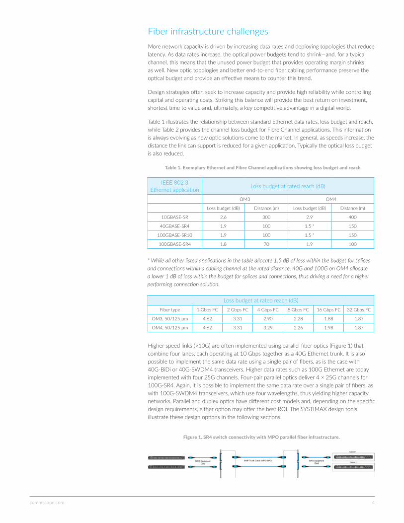
Table 1 illustrates the relationship between standard Ethernet data rates, loss budget and reach, while Table 2 provides the channel loss budget for Fibre Channel applications. This information is always evolving as new optic solutions come to the market. In general, as speeds increase, the distance the link can support is reduced for a given application. Typically the optical loss budget is also reduced.
Table 1. Exemplary Ethernet and Fibre Channel applications showing loss budget and reach
IEEE 802.3 Ethernet application Loss budget at rated reach (dB)
OM3 OM4
Loss budget (dB) Distance (m) Loss budget (dB) Distance (m)
10GBASE-SR 2.6 300 2.9 400
40GBASE-SR4 1.9 100 1.5 * 150
100GBASE-SR10 1.9 100 1.5 * 150
100GBASE-SR4 1.8 70 1.9 100
* While all other listed applications in the table allocate 1.5 dB of loss within the budget for splices and connections within a cabling channel at the rated distance, 40G and 100G on OM4 allocate a lower 1 dB of loss within the budget for splices and connections, thus driving a need for a higher performing connection solution.
Loss budget at rated reach (dB)Fiber type 1 Gbps FC 2 Gbps FC 4 Gbps FC 8 Gbps FC 16 Gbps FC 32 Gbps FC
OM3, 50/125 µm 4.62 3.31 2.90 2.28 1.88 1.87
OM4, 50/125 µm 4.62 3.31 3.29 2.26 1.98 1.87
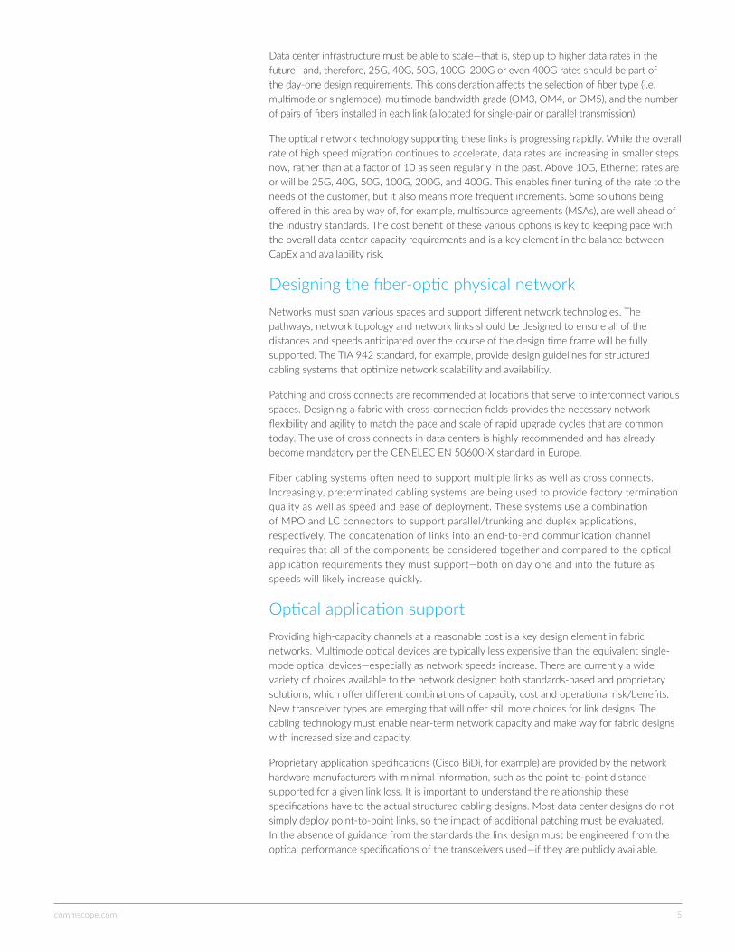
Higher speed links (>10G) are often implemented using parallel fiber optics (Figure 1) that combine four lanes, each operating at 10 Gbps together as a 40G Ethernet trunk. It is also possible to implement the same data rate using a single pair of fibers, as is the case with 40G-BiDi or 40G-SWDM4 transceivers. Higher data rates such as 100G Ethernet are today implemented with four 25G channels. Four-pair parallel optics deliver 4 × 25G channels for 100G-SR4. Again, it is possible to implement the same data rate over a single pair of fibers, as with 100G-SWDM4 transceivers, which use four wavelengths, thus yielding higher capacity networks. Parallel and duplex optics have different cost models and, depending on the specific design requirements, either option may offer the best ROI. The SYSTIMAX design tools illustrate these design options in the following sections.
Figure 1. SR4 switch connectivity with MPO parallel fiber infrastructure.
commscope.com 5
Data center infrastructure must be able to scale—that is, step up to higher data rates in the future—and, therefore, 25G, 40G, 50G, 100G, 200G or even 400G rates should be part of the day-one design requirements. This consideration affects the selection of fiber type (i.e. multimode or singlemode), multimode bandwidth grade (OM3, OM4, or OM5), and the number of pairs of fibers installed in each link (allocated for single-pair or parallel transmission).
The optical network technology supporting these links is progressing rapidly. While the overall rate of high speed migration continues to accelerate, data rates are increasing in smaller steps now, rather than at a factor of 10 as seen regularly in the past. Above 10G, Ethernet rates are or will be 25G, 40G, 50G, 100G, 200G, and 400G. This enables finer tuning of the rate to the needs of the customer, but it also means more frequent increments. Some solutions being offered in this area by way of, for example, multisource agreements (MSAs), are well ahead of the industry standards. The cost benefit of these various options is key to keeping pace with the overall data center capacity requirements and is a key element in the balance between CapEx and availability risk.
Designing the fiber-optic physical networkNetworks must span various spaces and support different network technologies. The pathways, network topology and network links should be designed to ensure all of the distances and speeds anticipated over the course of the design time frame will be fully supported. The TIA 942 standard, for example, provide design guidelines for structured cabling systems that optimize network scalability and availability.
Patching and cross connects are recommended at locations that serve to interconnect various spaces. Designing a fabric with cross-connection fields provides the necessary network flexibility and agility to match the pace and scale of rapid upgrade cycles that are common today. The use of cross connects in data centers is highly recommended and has already become mandatory per the CENELEC EN 50600-X standard in Europe.
Fiber cabling systems often need to support multiple links as well as cross connects. Increasingly, preterminated cabling systems are being used to provide factory termination quality as well as speed and ease of deployment. These systems use a combination of MPO and LC connectors to support parallel/trunking and duplex applications, respectively. The concatenation of links into an end-to-end communication channel requires that all of the components be considered together and compared to the optical application requirements they must support—both on day one and into the future as speeds will likely increase quickly.
Optical application supportProviding high-capacity channels at a reasonable cost is a key design element in fabric networks. Multimode optical devices are typically less expensive than the equivalent single-mode optical devices—especially as network speeds increase. There are currently a wide variety of choices available to the network designer: both standards-based and proprietary solutions, which offer different combinations of capacity, cost and operational risk/benefits. New transceiver types are emerging that will offer still more choices for link designs. The cabling technology must enable near-term network capacity and make way for fabric designs with increased size and capacity.
Proprietary application specifications (Cisco BiDi, for example) are provided by the network hardware manufacturers with minimal information, such as the point-to-point distance supported for a given link loss. It is important to understand the relationship these specifications have to the actual structured cabling designs. Most data center designs do not simply deploy point-to-point links, so the impact of additional patching must be evaluated. In the absence of guidance from the standards the link design must be engineered from the optical performance specifications of the transceivers used—if they are publicly available.

commscope.com 6
The design process begins with identifying the design options and questions to be considered. Which technologies does your equipment vendor support? Will the preferred topology and link distances work reliably with the network equipment being considered? If there are options available, which strategy will offer the best initial and long-term cost and highest reliability? Industry application standards provide some guidance but often do not account for the details of the topology that might be used. As more connections are added in more complex primary and secondary cabling routes, there is a need for guidance regarding the impact on the overall length that a network link can support for the performance of the particular cabling system components. Standards, unfortunately, do not include such guidance.
Application StandardIEEE
referenceMedia Speed Target distance
10-Gigabit Ethernet
10GBASE-SR
802.3ae
MMF
10 Gbps
33 m (OM1) to 550 m (OM4)
10GBASE-LR SMF 10 km
10GBASE-LX4 MMF 300 m
10GBASE-ER SMF 40 km
10GBASE-LRM 802.3aq MMF220 m (OM1/OM2) to
300 m (OM3)
25-Gigabit Ethernet
25GBASE-SR P802.3by MMF 25 Gbps70 m (OM3) 100 m
(OM4)
40-Gigabit Ethernet
40GBASE-SR4
802.3bm
MMF
40 Gbps
100 m (OM3) 150 m (OM4)
40GBASE-LR4 SMF 10 km
40GBASE-FR SMF 2 km
40GBASE-ER4 SMF 40 km
100-Gigabit Ethernet
100GBASE-SR10 MMF
100 Gbps
100 m (OM3) 150 m (OM4)
100GBASE-LR4 SMF 10 km
100GBASE-SR4 SMF70 m (OM3) 100 m
(OM4)
100GBASE-ER4 SMF 40 km
50G, 100G and 200G
50GBASE-SR
802.3cd
MMF
50 Gbps
100 m (OM4)
50GBASE-FR SMF 2 km
50GBASE-LR SMF 10 km
100GBASE-SR2 MMF
100 Gbps
100 m (OM4)
100GBASE-DR SMF 500 m
100GBASE-FR2 SMF 2 km
200GBASE-SR4 MMF
200 Gbps
100 m (OM4)
200-Gigabit Ethernet
200GBASE-DR4
P802.3bs
SMF 500 m
200GBASE-FR4 SMF 2 km
200GBASE-LR4 SMF 10 km
400-Gigabit Ethernet
400GBASE-SR16 MMF
400 Gbps
70 m (OM3) 100 m (OM4)
400GBASE-DR4 SMF 500 m
400GBASE-FR8 SMF 2 km
400GBASE-LR8 SMF 10 km
Table 2. IEEE Ethernet Standards
Table 2 above includes completed standards as well as some of those in development (in gray).
commscope.com 7
The media type and channel topology determines the maximum link lengths and maximum insertion losses—and this design must support the optical applications we intend to deploy now and in the future. But, what is the total loss from all of the connectivity in the link? How does the length and loss combination compare with the limits set by that application standard? Evaluating each case will yield a go/no-go decision for our design. CommScope offers tools that greatly assist in this process.
The day-two design considerations will often require that at least the next incremental network data rate must also be supported over the initial design topology. There are a number of combinations to consider. We must determine the actual (not average or typical) loss that any cabling element will contribute to the link under consideration. The bandwidth of the fiber media must be considered—OM3 having less bandwidth than OM4, for example, and OM5 WideBand multimode adding superior support for multiple wavelengths. We can also consider the possibility of parallel multifiber links and/or a mix of parallel and duplex links in the future. Finally, we can consider the impact of the scale and size of the data center—how does the length of the channels limit the choices we have for next-generation network data rates?
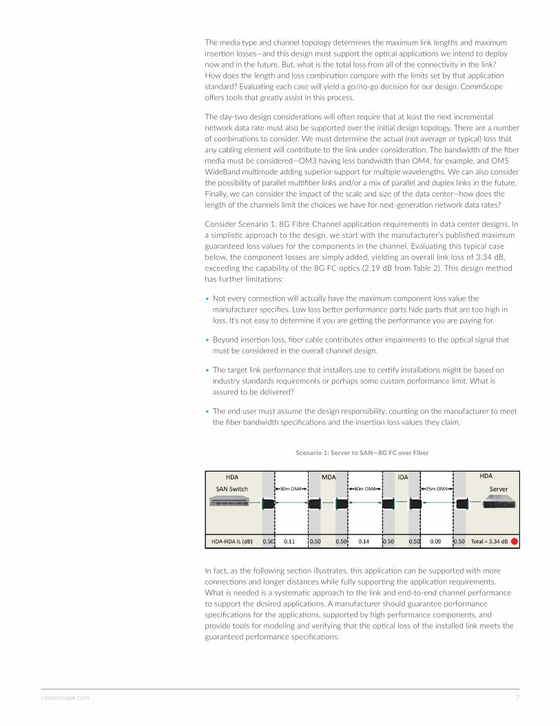
Consider Scenario 1, 8G Fibre Channel application requirements in data center designs. In a simplistic approach to the design, we start with the manufacturer’s published maximum guaranteed loss values for the components in the channel. Evaluating this typical case below, the component losses are simply added, yielding an overall link loss of 3.34 dB, exceeding the capability of the 8G FC optics (2.19 dB from Table 2). This design method has further limitations:
• Not every connection will actually have the maximum component loss value the manufacturer specifies. Low loss better performance parts hide parts that are too high in loss. It’s not easy to determine if you are getting the performance you are paying for.
• Beyond insertion loss, fiber cable contributes other impairments to the optical signal that must be considered in the overall channel design.
• The target link performance that installers use to certify installations might be based on industry standards requirements or perhaps some custom performance limit. What is assured to be delivered?
• The end user must assume the design responsibility, counting on the manufacturer to meet the fiber bandwidth specifications and the insertion loss values they claim.
Scenario 1: Server to SAN—8G FC over Fiber
In fact, as the following section illustrates, this application can be supported with more connections and longer distances while fully supporting the application requirements. What is needed is a systematic approach to the link and end-to-end channel performance to support the desired applications. A manufacturer should guarantee performance specifications for the applications, supported by high performance components, and provide tools for modeling and verifying that the optical loss of the installed link meets the guaranteed performance specifications.

commscope.com 8
CommScope performance specificationsThe previous elements of capacity, cabling topology, density, reach, and network hardware requirements may all play a role in support for a particular channel design for each application. Keeping options open means considering the permutations and combinations that make sense for your data center.
The CommScope SYSTIMAX low-loss (LL) and ultra-low-loss (ULL) solutions provide a modular preterminated solution that supports virtually all combinations of fiber types, channel connection counts and topology strategies for the various fabric network types available. The SYSTIMAX Performance Specifications cover the optical network options you might deploy on day one and well into the future. As new applications surface they are addressed in the SYSTIMAX Performance Specifications. The design of fiber infrastructures to support your network application(s)—standards based or not—can be ideally matched to your data center topology, media choice and scale. CommScope’s unique suite of tools gives you the ability to quickly and easily compare media and transmission options to deliver error-free designs that support today’s requirements as well as future applications. CommScope guarantees not only the channel performance in terms of allowable signal attenuation, but also that all applications specified by CommScope to be within the topology limits will operate.*
Table 3 below is taken directly from volume 6 of the - SYSTIMAX ULL Fiber Solutions for Ethernet and Fibre Channel Multimode Applications The guaranteed channel support for 8G FC shows combinations of connectivity that can be used to create channels with up to six LC and six MPO connectors, and then provides the maximum supported channel distance for LazrSPEED® 550 (OM4) fiber cabling. Looking back to the previous channel design example (the channel included 95 meters of OM4, with six MPO and six LC connections) SYSTIMAX low-loss solutions will support this topology with a maximum link length of 150 meters, meeting the design objective and far outperforming the generic design example.
Table 3. 8G Fibre Channel FC-PI-4 800-MX-SN supported distances with low-loss connection
Supportable distance ft (m)
LazrSPEED 550 with LC connections
#LC connections* with
1 MPO 2 MPOs 3 MPOs 4 MPOs 5 MPOs 6 MPOs
0 790 (240) 740 (225) 740 (225) 690 (210) 690 (210) 640 (195)
1 740 (225) 740 (225) 690 (210) 690 (210) 640 (195) 640 (195)
2 740 (225) 740 (225) 690 (210) 640 (195) 640 (195) 590 (180)
3 740 (225) 690 (210) 690 (210) 640 (195) 640 (195) 590 (180)
4 690 (210) 690 (210) 640 (195) 640 (195) 590 (180) 540 (165)
5 690 (210) 640 (195) 640 (195) 590 (180) 590 (180) 540 (165)
6 690 (210) 640 (195) 590 (180) 590 (180) 540 (165) 490 (150)
* Number of connections excludes the connection to the active device at each end of the channel.
Implementing the same channel using the SYSTIMAX ULL components will further enhance the design support capability. Table 4 shows the channel distance support increases by over 50 percent with a channel consisting of 6 LC and 6 MPO connections (typical of a triple-link configuration). We can also compare the distance support to a future generation of SAN link speed, 32G FC in Table 5. The maximum reach for this application is limited by the transceivers to 130 meters (i.e., no added connector losses). You will note that a triple link is supported to 110 meters. If we design the topology and reach appropriately we will be able to support the upgrade path to 32G FC in the future.
* Please refer to the System Warranty for full details and conditions

commscope.com 9
Table 5. 32 Gigabit Fibre Channel, 850 nm Serial (3200-M5x-SN) with ULL connections
Supportable distance ft (m)
LazrSPEED OM5 WideBand and LazrSPEED 550 with ULL connections
#LC connections* with
1 MPO 2 MPOs 3 MPOs 4 MPOs 5 MPOs 6 MPOs
0 430 (130) 430 (130) 430 (130) 430 (130) 430 (130) 410 (125)
1 430 (130) 430 (130) 430 (130) 430 (130) 410 (125) 410 (125)
2 430 (130) 430 (130) 430 (130) 430 (130) 410 (125) 390 (120)
3 430 (130) 430 (130) 430 (130) 410 (125) 390 (120) 390 (120)
4 430 (130) 430 (130) 410 (125) 410 (125) 390 (120) 380 (115)
5 430 (130) 430 (130) 410 (125) 390 (120) 380 (115) 360 (110)
6 430 (130) 410 (125) 390 (120) 390 (120) 380 (115) 360 (110)
* Number of connections excludes the connection to the active device at each end of the channel.
CommScope’s Application Assurance also extends to nonstandard vendor-specific networking options. Table A-4 (see Appendix) shows the SYSTIMAX Performance Specification support for Cisco’s 40G BiDi technology using OM4 and LL connectivity. Table A-5 illustrates ULL apparatus adding support for longer links in a channel. Selecting ULL connectivity and OM5 optical media further increases the reach of this application by over 35 percent for a triple-link channel.
An example of an extended-reach eSR4 option is shown in Table A-3. While extended reach optics are not currently defined within by standards, the SYSTIMAX Performance Specification identifies supportable distance and topologies that greatly exceed the generic guidance available from the manufacturer.
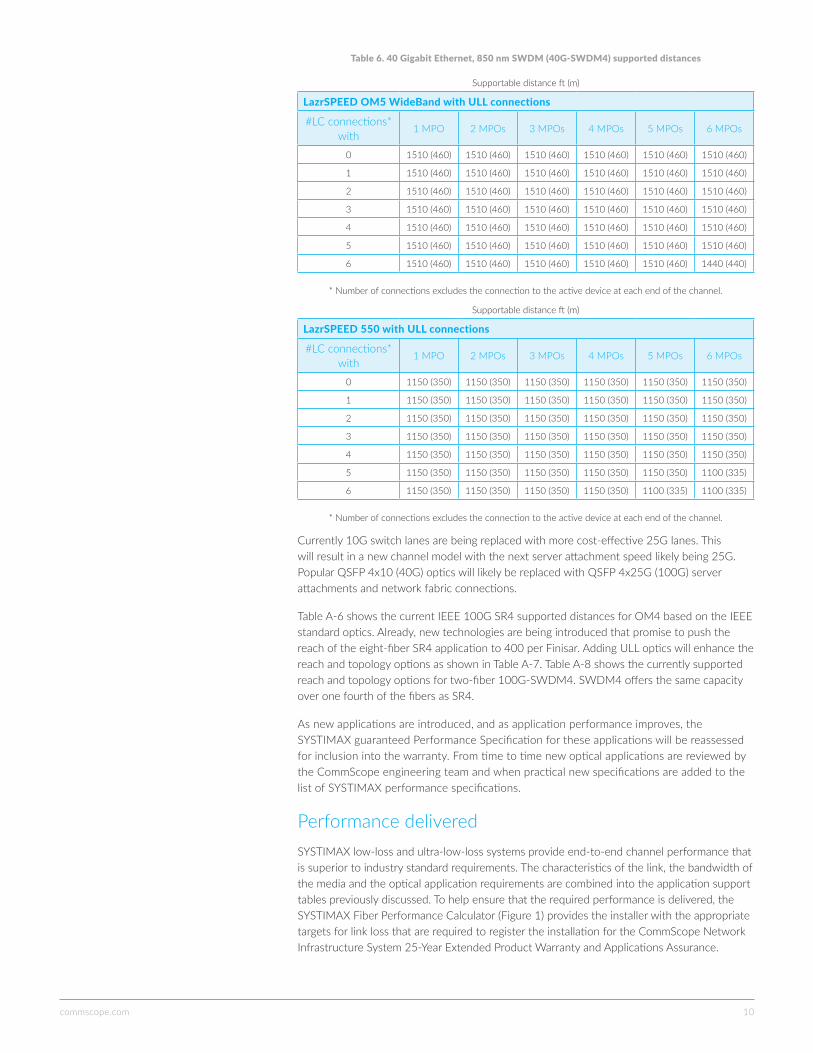
CommScope also offers support for emerging fiber media selections. OM5 multimode fiber better supports four wavelengths that effectively increase the capacity of each multimode fiber by a factor of four. New applications are emerging that will provide 40G and 100G Ethernet over a single pair of multimode fibers. As shown in Table 6, OM5 provides greater reach and topology choices for these multiwavelength applications.
Supportable distance ft (m)
LazrSPEED OM5 WideBand and LazrSPEED 550 with ULL connections
#LC connections* with
1 MPO 2 MPOs 3 MPOs 4 MPOs 5 MPOs 6 MPOs
0 980 (300) 980 (300) 950 (290) 920 (280) 890 (270) 890 (270)
1 980 (300) 950 (290) 950 (290) 920 (280) 890 (270) 850 (260)
2 980 (300) 950 (290) 920 (280) 890 (270) 850 (260) 820 (250)
3 950 (290) 920 (280) 890 (270) 890 (270) 850 (260) 820 (250)
4 950 (290) 920 (280) 890 (270) 850 (260) 820 (250) 790 (240)
5 920 (280) 890 (270) 850 (260) 820 (250) 820 (250) 790 (240)
6 890 (270) 890 (270) 850 (260) 820 (250) 790 (240) 750 (230)
* Number of connections excludes the connection to the active device at each end of the channel.
Table 4. 8G Fibre Channel FC-PI-4 800-MX-SN supported distances with ultra-low-loss connections
commscope.com 10
Currently 10G switch lanes are being replaced with more cost-effective 25G lanes. This will result in a new channel model with the next server attachment speed likely being 25G. Popular QSFP 4x10 (40G) optics will likely be replaced with QSFP 4x25G (100G) server attachments and network fabric connections.
Table A-6 shows the current IEEE 100G SR4 supported distances for OM4 based on the IEEE standard optics. Already, new technologies are being introduced that promise to push the reach of the eight-fiber SR4 application to 400 per Finisar. Adding ULL optics will enhance the reach and topology options as shown in Table A-7. Table A-8 shows the currently supported reach and topology options for two-fiber 100G-SWDM4. SWDM4 offers the same capacity over one fourth of the fibers as SR4.
As new applications are introduced, and as application performance improves, the SYSTIMAX guaranteed Performance Specification for these applications will be reassessed for inclusion into the warranty. From time to time new optical applications are reviewed by the CommScope engineering team and when practical new specifications are added to the list of SYSTIMAX performance specifications.
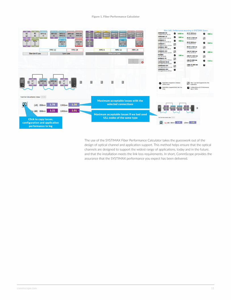
Performance deliveredSYSTIMAX low-loss and ultra-low-loss systems provide end-to-end channel performance that is superior to industry standard requirements. The characteristics of the link, the bandwidth of the media and the optical application requirements are combined into the application support tables previously discussed. To help ensure that the required performance is delivered, the SYSTIMAX Fiber Performance Calculator (Figure 1) provides the installer with the appropriate targets for link loss that are required to register the installation for the CommScope Network Infrastructure System 25-Year Extended Product Warranty and Applications Assurance.
Table 6. 40 Gigabit Ethernet, 850 nm SWDM (40G-SWDM4) supported distances
Supportable distance ft (m)
LazrSPEED OM5 WideBand with ULL connections
#LC connections* with
1 MPO 2 MPOs 3 MPOs 4 MPOs 5 MPOs 6 MPOs
0 1510 (460) 1510 (460) 1510 (460) 1510 (460) 1510 (460) 1510 (460)
1 1510 (460) 1510 (460) 1510 (460) 1510 (460) 1510 (460) 1510 (460)
2 1510 (460) 1510 (460) 1510 (460) 1510 (460) 1510 (460) 1510 (460)
3 1510 (460) 1510 (460) 1510 (460) 1510 (460) 1510 (460) 1510 (460)
4 1510 (460) 1510 (460) 1510 (460) 1510 (460) 1510 (460) 1510 (460)
5 1510 (460) 1510 (460) 1510 (460) 1510 (460) 1510 (460) 1510 (460)
6 1510 (460) 1510 (460) 1510 (460) 1510 (460) 1510 (460) 1440 (440)
* Number of connections excludes the connection to the active device at each end of the channel.
Supportable distance ft (m)
LazrSPEED 550 with ULL connections
#LC connections* with
1 MPO 2 MPOs 3 MPOs 4 MPOs 5 MPOs 6 MPOs
0 1150 (350) 1150 (350) 1150 (350) 1150 (350) 1150 (350) 1150 (350)
1 1150 (350) 1150 (350) 1150 (350) 1150 (350) 1150 (350) 1150 (350)
2 1150 (350) 1150 (350) 1150 (350) 1150 (350) 1150 (350) 1150 (350)
3 1150 (350) 1150 (350) 1150 (350) 1150 (350) 1150 (350) 1150 (350)
4 1150 (350) 1150 (350) 1150 (350) 1150 (350) 1150 (350) 1150 (350)
5 1150 (350) 1150 (350) 1150 (350) 1150 (350) 1150 (350) 1100 (335)
6 1150 (350) 1150 (350) 1150 (350) 1150 (350) 1100 (335) 1100 (335)
* Number of connections excludes the connection to the active device at each end of the channel.
commscope.com 11
The use of the SYSTIMAX Fiber Performance Calculator takes the guesswork out of the design of optical channel and application support. This method helps ensure that the optical channels are designed to support the widest range of applications, today and in the future, and that the installation meets the link loss requirements. In short, CommScope provides the assurance that the SYSTIMAX performance you expect has been delivered.
Figure 1. Fiber Performance Calculator
Maximum acceptable losses with the selected connections
Maximum acceptable losses if we had used ULL nodes of the same typeClick to copy losses,
configuration and application performance to log

commscope.com 12
ConclusionIn response to the demand for lower costs and higher capacities, new optical networking systems are quickly evolving to support the high speed migration underway in data centers. Data center cabling topologies are increasing in density, to support the any-to-any low-latency communications typically required by distributed cloud applications. Building backbone speeds are also increasing rapidly to extend support beyond voice and data into the new connected IoT building management and control systems with a multiplicity of end points aggregating bandwidth.
In the data center, the design of high-capacity channels can be complex, given that the number of channels must increase to build a mesh network while network data rates are increasing. Providing more data center capacity means pushing the limits of existing media and communication channel technologies. High-density fiber apparatus and the new fiber types such as OM5 wideband multimode will help chart a strategy to ensure the data center networks can rapidly increase capacity and seamlessly support new network technologies while minimizing the physical network spend.
Building backbone capacity is also greatly enhanced with the use of OM5 fiber, allowing familiar duplex topologies to support 40G and 100G duplex links with distances up to 400 meters or more.
Application design and engineered solutions from CommScope ensure reliable high-speed networks that meet the rigorous demands of current and future network capacity requirements. SYSTIMAX ULL systems provide greater reach for high-capacity links, design topology freedom to scale to very large and complex environments, and guaranteed application performance for both standards-based and emerging proprietary systems. CommScope’s unique approach to optical fiber network design and validation, coupled with the design and validation tools described in this guide, deliver the Applications Assurance you need, for today’s and tomorrow’s requirements.
Contact a CommScope representative or a certified PartnerPro member for a copy of the full SYSTIMAX Application Specifications.
SYSTIMAX 25-year system warranty
SYSTIMAX Fiber Performance Calculator

commscope.com 13
Appendix 1: Partial list of performance specifications
Table A-1. 40 Gigabit Ethernet, 850 nm Parallel (40GBASE-SR4) LL connections
LazrSPEED 550
#MPO connections*
1 MPO 2 MPOs 3 MPOs 4 MPOs 5 MPOs 6 MPOs
Distance ft (m) 570 (175) 560 (170) 540 (165) 510 (155) 490 (150) 460 (140)
LazrSPEED 300
#MPO connections*
1 MPO 2 MPOs 3 MPOs 4 MPOs 5 MPOs 6 MPOs
Distance ft (m) 460 (140) 440 (135) 430 (130) 410 (125) 390 (120) 380 (115)
* Number of connections excludes the connection to the active device at each end of the channel.
Table A-2. 40 Gigabit Ethernet, 850 nm 4-lane parallel (40GBASE-SR4) ULL connections
Supportable distance ft (m)
LazrSPEED OM5 WideBand and LazrSPEED 550
#LC connections* with
1 MPO 2 MPOs 3 MPOs 4 MPOs 5 MPOs 6 MPOs
0 710 (215) 690 (210) 670 (205) 640 (195) 620 (190) 610 (185)
1 690 (210) 670 (205) 660 (200) 620 (190) 610 (185) 590 (180)
2 670 (205) 660 (200) 640 (195) 620 (190) 590 (180) 570 (175)
3 670 (205) 640 (195) 620 (190) 610 (185) 570 (175) 560 (170)
4 660 (200) 620 (190) 610 (185) 590 (180) 560 (170) 540 (165)
5 640 (195) 610 (185) 590 (180) 570 (175) 540 (165) 520 (160)
6 620 (190) 610 (185) 570 (175) 560 (170) 520 (160) 490 (150)
* Number of connections excludes the connection to the active device at each end of the channel.
Table A-3. 40 Gigabit Ethernet, FIT extended reach 850 nm (40GBASE–eSR4) ULL connections
LazrSPEED OM5 WideBand and LazrSPEED 550
#LC connections* with
1 MPO 2 MPOs 3 MPOs 4 MPOs 5 MPOs 6 MPOs
0 1640 (500) 1640 (500) 1640 (500) 1640 (500) 1610 (490) 1610 (490)
1 1640 (500) 1640 (500) 1640 (500) 1640 (500) 1610 (490) 1610 (490)
2 1640 (500) 1640 (500) 1640 (500) 1610 (490) 1610 (490) 1570 (480)
3 1640 (500) 1640 (500) 1610 (490) 1610 (490) 1610 (490) 1570 (480)
4 1640 (500) 1640 (500) 1610 (490) 1610 (490) 1570 (480) 1570 (480)
5 1640 (500) 1610 (490) 1610 (490) 1570 (480) 1570 (480) 1540 (470)
6 1610 (490) 1610 (490) 1610 (490) 1570 (480) 1570 (480) 1540 (470)

commscope.com 14
Table A-4. 40 Gigabit Ethernet, Cisco “BiDi” (QSFP-40G-SR-BD) LL connections
Supportable distance ft (m)
LazrSPEED OM5 WideBand and LazrSPEED 550
#LC connections* with
1 MPO 2 MPOs 3 MPOs 4 MPOs 5 MPOs 6 MPOs
0 490 (150) 490 (150) 490 (150) 480 (145) 480 (145) 460 (140)
1 490 (150) 490 (150) 490 (150) 480 (145) 460 (140) 460 (140)
2 490 (150) 490 (150) 480 (145) 480 (145) 460 (140) 440 (135)
3 490 (150) 480 (145) 480 (145) 460 (140) 460 (140) 440 (135)
4 490 (150) 480 (145) 460 (140) 460 (140) 440 (135) 430 (130)
5 480 (145) 460 (140) 460 (140) 440 (135) 440 (135) 430 (130)
6 480 (145) 460 (140) 440 (135) 440 (135) 430 (130) 410 (125)
LazrSPEED OM5 WideBand with ULL connections
#LC connections* with
1 MPO 2 MPOs 3 MPOs 4 MPOs 5 MPOs 6 MPOs
0 690 (210) 690 (210) 660 (200) 660 (200) 620 (190) 620 (190)
1 690 (210) 660 (200) 660 (200) 660 (200) 620 (190) 620 (190)
2 660 (200) 660 (200) 660 (200) 620 (190) 620 (190) 590 (180)
3 660 (200) 660 (200) 620 (190) 620 (190) 620 (190) 590 (180)
4 660 (200) 660 (200) 620 (190) 620 (190) 590 (180) 590 (180)
5 660 (200) 620 (190) 620 (190) 590 (180) 590 (180) 590 (180)
6 620 (190) 620 (190) 620 (190) 590 (180) 590 (180) 560 (170)
Table A-5. 40 Gigabit Ethernet, Cisco “BiDi” (QSFP-40G-SR-BD) ULL connections
LazrSPEED 550 with ULL connections
#LC connections* with
1 MPO 2 MPOs 3 MPOs 4 MPOs 5 MPOs 6 MPOs
0 510 (155) 510 (155) 510 (155) 510 (155) 510 (155) 510 (155)
1 510 (155) 510 (155) 510 (155) 510 (155) 510 (155) 510 (155)
2 510 (155) 510 (155) 510 (155) 510 (155) 510 (155) 510 (155)
3 510 (155) 510 (155) 510 (155) 510 (155) 510 (155) 490 (150)
4 510 (155) 510 (155) 510 (155) 510 (155) 510 (155) 490 (150)
5 510 (155) 510 (155) 510 (155) 510 (155) 490 (150) 490 (150)
6 510 (155) 510 (155) 510 (155) 490 (150) 490 (150) 480 (145)
Table A-6. 100 Gigabit Ethernet, 850 nm four-lane parallel (100GBASE-SR4) LL Connections
* Number of connections excludes the connection to the active device at each end of the channel.
LazrSPEED 550 WideBand and LazrSPEED 550
#MPO connections*
1 MPO 2 MPOs 3 MPOs 4 MPOs 5 MPOs 6 MPOs
Distance ft (m) 390 (120) 390 (120) 370 (114) 370 (114) 350 (108) 350 (108)
LazrSPEED 300
#MPO connections*
1 MPO 2 MPOs 3 MPOs 4 MPOs 5 MPOs 6 MPOs
Distance ft (m) 280 (85) 280 (85) 280 (85) 260 (80) 260 (80) 250 (75)
* Number of connections excludes the connection to the active device at each end of the channel.

commscope.com 15
Table A-7. 100 Gigabit Ethernet, 850 nm four-lane parallel (100GBASE-SR4) ULL connections
Supportable distance ft (m)
LazrSPEED OM5 WideBand and LazrSPEED 550
#LC connections* with
1 MPO 2 MPOs 3 MPOs 4 MPOs 5 MPOs 6 MPOs
0 430 (130) 430 (130) 430 (130) 430 (130) 410 (125) 390 (120)
1 430 (130) 430 (130) 430 (130) 410 (125) 410 (125) 390 (120)
2 430 (130) 430 (130) 410 (125) 410 (125) 390 (120) 390 (120)
3 430 (130) 430 (130) 410 (125) 390 (120) 390 (120) 380 (115)
4 430 (130) 410 (125) 410 (125) 390 (120) 380 (115) 380 (115)
5 410 (125) 410 (125) 390 (120) 390 (120) 380 (115) 360 (110)
6 410 (125) 390 (120) 390 (120) 380 (115) 360 (110) 360 (110)
Table A-8. 100 Gigabit Ethernet, 850 nm SWDM (100G-SWDM4) ULL connections
LazrSPEED OM5 WideBand with ULL connections
#LC connections* with
1 MPO 2 MPOs 3 MPOs 4 MPOs 5 MPOs 6 MPOs
0 490 (150) 490 (150) 490 (150) 490 (150) 490 (150) 490 (150)
1 490 (150) 490 (150) 490 (150) 490 (150) 490 (150) 490 (150)
2 490 (150) 490 (150) 490 (150) 490 (150) 490 (150) 490 (150)
3 490 (150) 490 (150) 490 (150) 490 (150) 490 (150) 490 (150)
4 490 (150) 490 (150) 490 (150) 490 (150) 490 (150) 480 (145)
5 490 (150) 490 (150) 490 (150) 490 (150) 490 (150) 480 (145)
6 490 (150) 490 (150) 490 (150) 490 (150) 480 (145) 460 (140)
LazrSPEED 550 with ULL connections
#LC connections* with
1 MPO 2 MPOs 3 MPOs 4 MPOs 5 MPOs 6 MPOs
0 330 (100) 330 (100) 330 (100) 330 (100) 330 (100) 330 (100)
1 330 (100) 330 (100) 330 (100) 330 (100) 330 (100) 330 (100)
2 330 (100) 330 (100) 330 (100) 330 (100) 330 (100) 330 (100)
3 330 (100) 330 (100) 330 (100) 330 (100) 330 (100) 330 (100)
4 330 (100) 330 (100) 330 (100) 330 (100) 330 (100) 330 (100)
5 330 (100) 330 (100) 330 (100) 330 (100) 330 (100) 330 (100)
6 330 (100) 330 (100) 330 (100) 330 (100) 330 (100) 330 (100)
* Number of connections excludes the connection to the active device at each end of the channel.
commscope.comVisit our website or contact your local CommScope representative for more information.
© 2017 CommScope, Inc. All rights reserved.
All trademarks identified by ® or ™ are registered trademarks or trademarks, respectively, of CommScope, Inc. This document is for planning purposes only and is not intended to modify or supplement any specifications or warranties relating to CommScope products or services. CommScope is committed to the highest standards of business integrity and environmental sustainability, with a number of CommScope’s facilities across the globe certified in accordance with international standards, including ISO 9001, TL 9000, and ISO 14001. Further information regarding CommScope’s commitment can be found at www.commscope.com/About-Us/Corporate-Responsibility-and-Sustainability.
TP-111819-EN (05/17)
Everyone communicates. It’s the essence of the human experience. How we communicate is evolving. Technology is reshaping the way we live, learn and thrive. The epicenter of this transformation is the network—our passion. Our experts are rethinking the purpose, role and usage of networks to help our customers increase bandwidth, expand capacity, enhance efficiency, speed deployment and simplify migration. From remote cell sites to massive sports arenas, from busy airports to state-of-the-art data centers—we provide the essential expertise and vital infrastructure your business needs to succeed. The world’s most advanced networks rely on CommScope connectivity.