sze chern tan - school of informatics · supporting visualization and analysis of requirements...
TRANSCRIPT

Supporting Visualization and Analysis of
Requirements Evolution
Sze Chern TanT
HE
U N I V E RS
IT
Y
OF
ED I N B U
RG
H
Master of Science
Computer Science
School of Informatics
University of Edinburgh
2009

Abstract
Requirements evolution captures information about how software systems change as a
result of changes in requirements. The goal of this project is to identify how existing
requirements engineering methods, tools and models can be extended to to support the
analysis of requirements evolution. It is hoped that by providing a tool for analyzing
requirements evolution, our work will spur further research on requirements evolution,
thereby enriching the field of requirements engineering. We present a design which
supports requirements evolution analysis within conventional requirement engineering
processes by building on the models proposed by researchers. We implement this
design as a plug-in for the Eclipse IDE. Our plug-in supports requirement analysis by
providing visualizations as means of presenting requirement changes and evolution.
i

Acknowledgements
In delivering this thesis, I have been fortunate enough to have been assisted by many
individuals whom I wish to acknowledge here. First and foremost, a heart-felt note
of thanks to Massimo Felici, my thesis supervisor, for his generosity in dispensing
advice, his willingness to answer my million and one questions, his insightful advice,
his honest feedback to my ideas, and for giving me endless weeks of sleepless nights
working on this project.
I wish to acknowledge the works of the individuals and groups who contributed
to several free code libraries which I’ve reused to deliver the final software tool: Joe
Walnes and the contributers to the XStream library which I’ve used for serializing and
deserializing Java objects to XML; David Gilbert and the contributers to the JFreeChart
library which provided me with the capability to build the beautiful charts used in
the visualizations; Neil Fraser for his implementation of Myer’s diff algorithm which
I’ve leveraged on to identify requirement attribute changes; and Tim Fennell, whose
string comparator algorithm is used to replace Sun’s ’broken’ implementation of string
sorting in Java. Finally, I wish to thank Mark James for making his Silk icon set, which
is used throughout the software, for giving away such a beautiful set of icons for free.
To my family, from whom I have received so much encouragement and support,
words fail to convey the depth of my love and appreciation.
My heartfelt gratitude to my pet penguin for figuring out LaTeX, and having to sit
through countless hours of spell-checking.
And to Gloria, for her energy, endless patience, and my source of inspiration.
ii

Declaration
I declare that this thesis was composed by myself, that the work contained herein is
my own except where explicitly stated otherwise in the text, and that this work has not
been submitted for any other degree or professional qualification except as specified.
(Sze Chern Tan)
iii

To my parents.
iv

Table of Contents
1 Introduction 11.1 Motivations . . . . . . . . . . . . . . . . . . . . . . . . . . . . . . . 2
1.2 Objectives . . . . . . . . . . . . . . . . . . . . . . . . . . . . . . . . 3
1.3 Structure . . . . . . . . . . . . . . . . . . . . . . . . . . . . . . . . . 4
2 On Requirements Evolution 52.1 Requirements evolution . . . . . . . . . . . . . . . . . . . . . . . . . 6
2.2 Requirements traceability . . . . . . . . . . . . . . . . . . . . . . . . 9
2.2.1 Requirements traceability techniques . . . . . . . . . . . . . 9
2.3 Empirical analysis of requirements evolution . . . . . . . . . . . . . 10
2.4 Summary . . . . . . . . . . . . . . . . . . . . . . . . . . . . . . . . 13
3 Tool Support for Requirements Evolution 153.1 Implementations of requirements management tools . . . . . . . . . . 17
3.1.1 Evaluation criteria . . . . . . . . . . . . . . . . . . . . . . . 17
3.1.2 Rational RequisitePro . . . . . . . . . . . . . . . . . . . . . 21
3.1.3 Open Source Requirements Management Tool (OSRMT) . . . 23
3.1.4 JRequisite . . . . . . . . . . . . . . . . . . . . . . . . . . . . 24
3.1.5 JFeature . . . . . . . . . . . . . . . . . . . . . . . . . . . . . 25
3.2 Summary . . . . . . . . . . . . . . . . . . . . . . . . . . . . . . . . 26
4 Design Rationale 284.1 The system architecture . . . . . . . . . . . . . . . . . . . . . . . . . 29
4.2 The requirements model . . . . . . . . . . . . . . . . . . . . . . . . 30
4.2.1 Open Requirements Management Framework . . . . . . . . . 30
4.2.2 Class diagram . . . . . . . . . . . . . . . . . . . . . . . . . . 32
4.3 Requirement change history model . . . . . . . . . . . . . . . . . . . 36
4.3.1 Modeling requirement changes . . . . . . . . . . . . . . . . . 37
v

4.3.2 Classifying requirement changes . . . . . . . . . . . . . . . . 39
4.3.3 Visualizing requirement changes . . . . . . . . . . . . . . . . 40
4.4 Summary . . . . . . . . . . . . . . . . . . . . . . . . . . . . . . . . 41
5 Implementation 435.1 Eclipse plug-in architecture . . . . . . . . . . . . . . . . . . . . . . . 43
5.2 Views . . . . . . . . . . . . . . . . . . . . . . . . . . . . . . . . . . 44
5.2.1 System navigation . . . . . . . . . . . . . . . . . . . . . . . 46
5.2.2 Content editors . . . . . . . . . . . . . . . . . . . . . . . . . 49
5.2.3 Dialogs . . . . . . . . . . . . . . . . . . . . . . . . . . . . . 52
5.3 Controllers . . . . . . . . . . . . . . . . . . . . . . . . . . . . . . . 53
5.3.1 Plug-in controller . . . . . . . . . . . . . . . . . . . . . . . . 53
5.3.2 Requirement model controller . . . . . . . . . . . . . . . . . 54
5.3.3 Change registry controller . . . . . . . . . . . . . . . . . . . 54
5.3.4 Evolution inference controller . . . . . . . . . . . . . . . . . 57
5.3.5 Traceability controller . . . . . . . . . . . . . . . . . . . . . 58
5.3.6 Data persistence . . . . . . . . . . . . . . . . . . . . . . . . 58
5.4 Visualizations . . . . . . . . . . . . . . . . . . . . . . . . . . . . . . 59
5.4.1 Change history table . . . . . . . . . . . . . . . . . . . . . . 59
5.4.2 Workflow graph . . . . . . . . . . . . . . . . . . . . . . . . . 60
5.4.3 Charts . . . . . . . . . . . . . . . . . . . . . . . . . . . . . . 62
5.4.4 Plotting the charts . . . . . . . . . . . . . . . . . . . . . . . 64
5.4.5 Dependency graph . . . . . . . . . . . . . . . . . . . . . . . 65
5.5 Testing activities . . . . . . . . . . . . . . . . . . . . . . . . . . . . 66
5.5.1 Unit testing . . . . . . . . . . . . . . . . . . . . . . . . . . . 67
5.5.2 GUI testing . . . . . . . . . . . . . . . . . . . . . . . . . . . 71
5.6 Summary . . . . . . . . . . . . . . . . . . . . . . . . . . . . . . . . 72
6 Post-implementation Evaluation 746.1 Functional evaluation . . . . . . . . . . . . . . . . . . . . . . . . . . 74
6.1.1 Requirements elicitation . . . . . . . . . . . . . . . . . . . . 75
6.1.2 Requirements management . . . . . . . . . . . . . . . . . . . 76
6.1.3 Change control . . . . . . . . . . . . . . . . . . . . . . . . . 77
6.1.4 Analysis . . . . . . . . . . . . . . . . . . . . . . . . . . . . 78
6.1.5 Non-functional aspects . . . . . . . . . . . . . . . . . . . . . 79
6.2 Supporting theoretical evolution models . . . . . . . . . . . . . . . . 80
vi

6.2.1 Evolution of requirements . . . . . . . . . . . . . . . . . . . 80
6.2.2 Evolution types and causes . . . . . . . . . . . . . . . . . . . 81
6.2.3 Analysis of requirements evolution . . . . . . . . . . . . . . 84
6.3 Improvements . . . . . . . . . . . . . . . . . . . . . . . . . . . . . . 88
6.3.1 Classification of requirement lifecycle events as requirement
change . . . . . . . . . . . . . . . . . . . . . . . . . . . . . 88
6.3.2 Multiple inheritance for projects . . . . . . . . . . . . . . . . 91
6.3.3 Complete visual histories of requirements . . . . . . . . . . . 94
6.4 Summary . . . . . . . . . . . . . . . . . . . . . . . . . . . . . . . . 95
7 Conclusions 967.1 Outcomes . . . . . . . . . . . . . . . . . . . . . . . . . . . . . . . . 96
7.2 Challenges . . . . . . . . . . . . . . . . . . . . . . . . . . . . . . . . 98
7.3 Lessons learned . . . . . . . . . . . . . . . . . . . . . . . . . . . . . 99
7.4 Future work . . . . . . . . . . . . . . . . . . . . . . . . . . . . . . . 99
7.4.1 Analyzing unstructured requirements . . . . . . . . . . . . . 100
7.4.2 Reports . . . . . . . . . . . . . . . . . . . . . . . . . . . . . 100
7.4.3 Linkages to external software artifacts . . . . . . . . . . . . . 100
7.4.4 Causality analysis of requirement change . . . . . . . . . . . 101
7.4.5 Multi-user environment . . . . . . . . . . . . . . . . . . . . . 101
7.4.6 Implementation of Requirement Viewpoints . . . . . . . . . . 102
A Installation 104A.1 Pre-requisites . . . . . . . . . . . . . . . . . . . . . . . . . . . . . . 104
A.1.1 Project jar files . . . . . . . . . . . . . . . . . . . . . . . . 104
A.1.2 Eclipse . . . . . . . . . . . . . . . . . . . . . . . . . . . . . 104
A.1.3 Eclipse GEF Zest . . . . . . . . . . . . . . . . . . . . . . . . 105
A.2 Installation . . . . . . . . . . . . . . . . . . . . . . . . . . . . . . . 106
B Evaluating Requirements Management Tools 108B.1 Survey questionnaire . . . . . . . . . . . . . . . . . . . . . . . . . . 108
B.2 Survey results . . . . . . . . . . . . . . . . . . . . . . . . . . . . . . 111
Bibliography 114
vii

List of Figures
2.1 Requirements stability index (Anderson and Felici, 2002) . . . . . . . 11
2.2 Historical requirements maturity index (Anderson and Felici, 2002) . 12
3.1 Requirements management software software architecture (Lormans
et al., 2004) . . . . . . . . . . . . . . . . . . . . . . . . . . . . . . . 16
3.2 Screenshot of Rational RequisitePro . . . . . . . . . . . . . . . . . . 22
3.3 Traceability analysis in Rational RequisitePro . . . . . . . . . . . . . 22
3.4 Screenshot of the Open Source Requirements Management Tool . . . 23
3.5 Screenshot of the JRequisite Eclipse plug-in . . . . . . . . . . . . . . 25
3.6 Screenshot of the JFeature Eclipse plug-in . . . . . . . . . . . . . . . 26
4.1 System architecture of the Requirements Evolution Plug-in . . . . . . 29
4.2 ORMF Requirement Model . . . . . . . . . . . . . . . . . . . . . . . 31
4.3 Class diagram of the requirements model . . . . . . . . . . . . . . . 32
4.4 The requirement life-cycle . . . . . . . . . . . . . . . . . . . . . . . 35
4.5 Semantic traceability links . . . . . . . . . . . . . . . . . . . . . . . 38
4.6 A ChangeRecord is used for recording requirement change . . . . . . 39
5.1 The Eclipse plug-in architecture . . . . . . . . . . . . . . . . . . . . 44
5.2 Eclipse user interface components . . . . . . . . . . . . . . . . . . . 45
5.3 The System Navigation view part . . . . . . . . . . . . . . . . . . . . 47
5.4 The context menu . . . . . . . . . . . . . . . . . . . . . . . . . . . . 48
5.5 The Eclipse selection service . . . . . . . . . . . . . . . . . . . . . . 49
5.6 A content editor . . . . . . . . . . . . . . . . . . . . . . . . . . . . . 50
5.7 The message manager displaying an error message . . . . . . . . . . 51
5.8 Dialog windows in the Requirements Evolution plug-in . . . . . . . . 52
5.9 Information stored in change records . . . . . . . . . . . . . . . . . . 56
5.10 Customization options for the EvolutionInference controller . . . 58
viii

5.11 Change history table . . . . . . . . . . . . . . . . . . . . . . . . . . 59
5.12 Workflow graph . . . . . . . . . . . . . . . . . . . . . . . . . . . . . 61
5.13 Chart visualization . . . . . . . . . . . . . . . . . . . . . . . . . . . 65
5.14 Dependency graph . . . . . . . . . . . . . . . . . . . . . . . . . . . 66
5.15 A test case in PDE JUnit with statement coverage analysis from EclEmma 68
5.16 Overall test coverage for the project . . . . . . . . . . . . . . . . . . 69
5.17 Test coverage for the controller package . . . . . . . . . . . . . . 70
5.18 Test coverage for the model and util packages . . . . . . . . . . . . 71
6.1 History types captured in the Requirements Evolution Visualization tool 81
6.2 Creating new change types . . . . . . . . . . . . . . . . . . . . . . . 83
6.3 Mapping change types to requirement changes . . . . . . . . . . . . . 83
6.4 Effects of classification changes . . . . . . . . . . . . . . . . . . . . 84
6.5 van Lamweerde’s evolution cycle . . . . . . . . . . . . . . . . . . . . 85
6.6 Concept of variants and revisions in our software . . . . . . . . . . . 86
6.7 Visualizing requirement change histories . . . . . . . . . . . . . . . . 87
6.8 Requirement evolution metrics . . . . . . . . . . . . . . . . . . . . . 88
6.9 Effect of inheritance change type on project metrics . . . . . . . . . . 90
6.10 Visualizing a project inheritance tree . . . . . . . . . . . . . . . . . . 91
6.11 Detecting requirement variants . . . . . . . . . . . . . . . . . . . . . 92
6.12 Determining ordering in different release branches . . . . . . . . . . 94
6.13 Visual history illustrating changes over the lifetime of a requirement . 95
A.1 Updating Eclipse . . . . . . . . . . . . . . . . . . . . . . . . . . . . 105
A.2 Eclipse Software Update dialog . . . . . . . . . . . . . . . . . . . . . 106
A.3 Launching the Requirements Evolution plug-in . . . . . . . . . . . . 107
ix

List of Tables
1.1 Summary of hypotheses . . . . . . . . . . . . . . . . . . . . . . . . . 4
2.1 Types of requirements, classified based on volatility to change (Harker
et al., 1993) . . . . . . . . . . . . . . . . . . . . . . . . . . . . . . . 8
3.1 Desirable information to capture about requirements . . . . . . . . . 19
3.2 Desirable information to capture about requirement changes . . . . . 20
4.1 Contextual information about requirement changes . . . . . . . . . . 37
4.2 Classification of requirement changes . . . . . . . . . . . . . . . . . 39
4.3 Visualizations of project changes . . . . . . . . . . . . . . . . . . . . 40
4.4 Visualizations of requirement changes . . . . . . . . . . . . . . . . . 41
6.1 Evaluating requirements elicitation functionality . . . . . . . . . . . . 76
6.2 Evaluating requirements management functionality . . . . . . . . . . 77
6.3 Evaluating change control functionality . . . . . . . . . . . . . . . . 78
6.4 Evaluating analysis functionality . . . . . . . . . . . . . . . . . . . . 79
B.1 Evaluation criteria for requirements management software . . . . . . 108
B.2 Summarised evaluation of requirements management software . . . . 111
x

Chapter 1
Introduction
Software requirements, and the software system itself, will inevitably change over
the lifetime of the software. When initially defined during the early stages of sys-
tem development, requirements are presented by the customer to the developer from a
high-level business-oriented viewpoint; the developer then expands on these initial re-
quirements to produce a set of design documents. Gradually, as the project progresses,
these requirements become clearer and more precise as aspects such as the projects
technical environment are more clearly defined. At the same time, these requirements
may change due to changes in the customers needs, organization, the environment in
which the system will be operated in, or simply because the requirements were cap-
tured inaccurately during the initial elicitation phase.
Requirements engineering is primarily concerned with correctly capturing require-
ments and subsequently how changes to those requirements are managed (Sommerville
and Sawyer, 1997); the study of requirements evolution is further concerned with cap-
turing the context and design decisions associated with each change. In short, require-
ments evolution seeks to understand why, when, and how requirements change over the
lifetime of a system (from conception through post-release maintenance and ultimately
to decommission), especially between different generations (i.e. releases) of said sys-
tem. As in biological evolution, software requirements change through evolutionary
mechanisms over time, producing successors or variants.
Earlier work within the field of requirements analysis largely focused on traceabil-
ity aspects i.e. the ability to document the life of a requirement (such as when and
how it came into being) to enable one to trace back to the origin of each requirement
(Pinheiro and Goguen, 1996; Sommerville and Sawyer, 1997). This ensures that de-
sign changes are captured and controlled within the overall development process. Re-
1

Chapter 1. Introduction 2
quirements evolution complements this by providing information about how different
aspects of the requirement change over the course of a system’s lifetime.
1.1 Motivations
Understanding the situations and rate at which requirements evolve can provide insight
into the effectiveness of existing development processes and management strategies. A
body of knowledge on requirements evolution can be used as a tool to aid in planning
activities pertaining to effort estimation and scheduling accuracy for a given team or
type of project. Analysis of how certain functions for a given system change over the
course of development, and understanding the extent of the impact of the change, may
shed light on how to streamline the development process for similar systems in the
future.
Different requirements within a system have different distributions of change; by
their nature, some requirements may remain relatively static (e.g. architectural or sys-
tem requirements), while others may constantly change (e.g. user requirements for a
user interface). Consequently some requirements are relatively harder to set in stone
during the early stages of a project. In projects which choose to proceed in a linear
manner – from requirements elicitation to design to implementation, with minimal
back-tracking – knowing which requirements have a high likelihood of change may
save time and effort spent on writing a ‘complete’ requirements specification docu-
ment before implementation can proceed. Having the data available allows developers
to better time-manage their requirements elicitation phase. If the types of changes,
where and when those changes would likely to occur can be anticipated, Harker et al
assert that developers can then devise strategies for coping with those changes during
system development – developers may either re-evaluate their development methodol-
ogy to determine how well change management is supported or alternatively design the
system in such a way that changes can be accomodated with minimal rewrites (Harker
et al., 1993).
Requirements evolution can also be used to support the development of software
product lines. Companies may release different software variants that share similar
core requirements and architecture yet sufficiently different in terms of advanced func-
tions to warrant different development teams. In order to identify which requirements
can be considered to be core, the developer needs to know the relationships between
every requirement as well as between each requirement and the design. Furthermore,

Chapter 1. Introduction 3
core requirements should exhibit a certain level of stability between variants so as to
minimize the impact of changes and reduce the cost of code maintenance.
1.2 Objectives
Requirements evolution captures information about how software systems change as a
result of changes in requirements, hence increasing our body of knowledge in software
engineering. This project identifies how existing requirements engineering methods,
tools and models can be extended to capture requirements evolution. Researchers have
proposed different means of capturing this data; this project is concerned with identi-
fying how such means can be put together to provide a solution that supports require-
ments evolution analysis. The current state of tool support does not provide sufficient
data with which to present a comprehensive view of requirements evolution. Our hy-
pothesis is that it is possible to extend existing requirements engineering methods,
tools and models to support the analysis of requirements evolution.
By providing a visual model of this evolution, it provides a more accessible way
for project stakeholders to evaluate the impact of these changes. Consequently, this
understanding will allow us to cope with requirement changes better, and perhaps pro-
vide better models for software development in the future. Analyzing requirements
evolution enhances our understanding of how software requirements evolve over time
within a single project and over multiple project variants.
Finally, analysis of requirements evolution is as much an analysis of the require-
ments management process itself as it is about capturing an organizations ability to
cope with requirement changes. Thus, studying the requirements evolution of a sys-
tem may reveal the characteristics of the underlying organizational and development
processes, thus enabling us to relate the effects of requirements evolution on the prop-
erties of the system.

Chapter 1. Introduction 4
Table 1.1: Summary of hypotheses
Hypothesis Statement
H1 Existing requirements engineering methods, tools and models can be extended
to capture requirements evolution.
H2 Analyzing requirements evolution enhances our understanding of how soft-
ware requirements evolve over time within a single project and over multiple
project variants.
H3 The requirements evolution of a system reveals characteristics of the underly-
ing organizational and development processes.
Table 1.1 summarises the hypotheses identified for our project. While this project
may not have sufficient time to fully explore hypotheses H2 and H3 in detail, it is hoped
that achieving H1 – providing the tool support for analyzing requirements evolution –
will spur further research that will.
1.3 Structure
This thesis is structured as follows. Chapter 1 aims to provide the reader with an under-
standing of the scope of this project, as well as the project objectives and motivations
within the context of requirements engineering. Chapter 2 provides background on re-
lated work within the field of requirements engineering, in particular current research
into requirements evolution and the extent to which existing work supports require-
ments evolution analysis. This is followed by Chapter 3 which analyzes existing re-
quirements engineering processes, and tools, and provides an overview of the extent of
tool support for requirements evolution today. In Chapter 4, we design a requirements
management tool intended to provide analytical support for requirements evolution,
primarily based on the lessons learned from the previous chapters. Details of how
we implemented the software tool based on this design are provided in Chapter 5. In
Chapter 6, we examine our implementation against published models. We evaluate
some of the implications of our design, providing an analysis of our observations, and
then highlight the subsequent improvements made to the original design. Finally, in
Chapter 7 we summarise our conclusions, the challenges and lessons we have learnt
from this project, as well as provide suggestions for future work.

Chapter 2
On Requirements Evolution
Conventional software development processes, such as the waterfall or spiral method-
ologies, are fairly linear – projects proceed from the requirements engineering phase
to the design and implementation phases (Pressman, 2005). On the other hand, ag-
ile methodologies tend to forego formal requirements engineering phases in favour of
light-weight processes, substituting formal documentation with user stories. Yet, no
matter whether the project uses a heavy or agile methodology, the system design and
implementation ultimately hinges on identifying a fixed set of requirements prior to
implementation.
The implications of these processes is that requirement changes in the late stages
of the project requirement requires a re-evaluation of the design and implementation
done in the earlier stages to ensure the system fulfills the modified requirements. To
avoid this, development teams may opt to lock the requirements after the requirements
engineering phase is complete; any changes to the requirements are addressed in the
next release or cycle of the process. Requirements management tools available today
attempt to introduce a more flexible process by providing impact analysis of require-
ment changes. Using traceability mechanisms, these tools allow developers to quickly
gauge the feasibility of making a change during the current development cycle. How-
ever, much of the focus thus far is on the managing the impacts of change, rather
than on understanding those changes itself. In fact, there are relatively few models for
systematically managing requirements evolution (Lam and Loomes, 1998).
Requirements engineering researchers suggest that the traditional approach can be
improved (Harker et al., 1993) – if project management understand what types of
changes occur in their project, as well as when and where those changes are likely to
occur, then perhaps existing development processes can be modified to accomodate
5

Chapter 2. On Requirements Evolution 6
requirement changes that naturally arise during system development. Alternatively, if
the developer is able to identify which portions of the system are prone to changes
using a body of knowledge compiled from analyzing similar systems, then it would
enable the developer to re-evaluate whether his/her software design is able to cope
with such changes, preferably early in the project.
In order to tackle this problem, there is a need to recognise that there are various
forms of changes that can occur within a software system: changes may occur at the
design level (e.g. architecture, product domain); at the opposite end, there may be
changes which occur at the physical level, i.e. how the system interacts with its users
and environment. Requirements evolution is considered as a middle-ground between
design and physical change, and thus the natural place where to capture information
about the evolution of computer-based systems (Felici, 2003).
2.1 Requirements evolution
The study of evolution is focused on the study of the changes in an object’s character-
istics or traits over time, both within a single generation and over multiple generations.
In terms of requirements evolution, this means that one is interested in capturing and
understanding changes of a software system’s feature within a single system release
(version), and over multiple releases (versions). Lamsweerde termed the analysis of
requirement changes within a single release as intra-version evolution, and the analysis
of requirements changes over different releases as inter-version evolution (van Lam-
sweerde, 2009). Changes in a system over a single release are generally made over
the course of development; each change produces a revision of the system. It is par-
ticularly meaningful for the developer to determine the stability of the system under
development before release into production. Changes over multiple releases produces
variants of the same system, and are generally more driven by software maintenance
or commercial factors. This distinction between revisions and variants creates a more
granular unit of requirement change, as requirement changes exist for both a variation
and a revision of the same requirement. Depending on the development process, it may
reveal a tendency for developers to only accept smaller units of change (e.g. improving
or correcting existing requirements) during a revision, and only make major changes
(e.g. adding new requirements) between variants, or vice versa.
Requirements management is a decision-oriented process, rather than an activity
or product-oriented process. The conventional approach is to store only the artifacts’

Chapter 2. On Requirements Evolution 7
history, but this provides insufficient information about the decision itself. Require-
ments (and any changes) depend on the details of the situation or environment from
which they arise (Pinheiro and Goguen, 1996). Any change can only happen after the
developer has weighed the pros and cons of each option (i.e. whether to accept, defer
or reject requirement changes). We are interested in not only capturing the state of a
requirement before and after a change, but also the rationale and context behind each
decision. Rolland suggests that the context within which change takes place can be
sufficiently captured if the following four pieces of information are stored: the situa-
tion in which the change takes place (i.e. the requirement being changed, and when
the change was proposed), the decision that was made (i.e. whether the change is ac-
cepted, rejected, deferred etc), the action (i.e. the change itself), and the argument (i.e.
the rationale to support the decision) (Rolland and Prakash, 1994).
There are various forms of change that can occur throughout a system; there have
been multiple variations of definitions given to categorise types of changes. One sug-
gested taxonomy of changes follows a fairly basic principle: changes can be grouped
based on the effects each change has on the requirement - a change may affect the inner
attributes or properties of the requirement (e.g. change in the name or description), or it
may affect the requirement’s relationship with its environment (e.g. change in relation-
ships with other requirements or artifacts), or even affect the state of the requirement
itself (e.g. a new requirement is added, or an existing requirement is removed) (Rol-
land and Prakash, 1994).These three groups may be further subdivided to provided a
fine-grained level of categorisation. For instance, changes in the relationship between
two requirements may be classified as extensions (one requirement extends the other),
derivations (one requirement is derived from the other), replacement (one requirement
obsoletes the other) and so on (van Lamsweerde, 2009).
Design artifacts produced over the course of the requirements engineering process,
i.e. the specifications, are objects which progressively evolve as a result of decisions
and changes made by requirements engineers. In conventional requirements manage-
ment tools, only modifications to the requirement’s contents are captured; however,
an object’s complete evolutionary history should encompass changes in the object’s
contents, relationships with other objects, and relationships with objects from which it
is derived from. A complete history of a given object’s evolutionary path is necessary
to accurately represent the development history of the object (Rolland and Prakash,
1994) – the history should comprise of three elements - the object’s inner history, spa-
tial history and temporal history. Inner history tracks changes in the object’s inner

Chapter 2. On Requirements Evolution 8
attributes, spatial history tracks changes in the object’s environment, and temporal his-
tory tracks changes in the object’s type. A requirement for a particular project is a
design artifact in the requirements engineering process, with various sections contain-
ing different information describing the specification, linkages to other requirements,
and intrinsic properties associated with it (for instance, a requirement’s type and prior-
ity level). Hence it should have an inner history to track changes in the document itself,
a spatial history to track changes in the external linkages, and a temporal history. All
of these histories combined provide a complete picture of the requirement’s evolution.
A different approach is to classify the requirements such that it allows one to infer
the stability of a requirement based on the source of the requirement, rather than by the
changes itself. The source from which a requirement originally arises may be useful
in identifying beforehand whether it is susceptible to change (Harker et al., 1993). For
instance, system requirements which are required to satisfy a core business function
are most likely to be stable (Harker et al defined these as enduring requirements). On
the other hand, there are also changing requirements which are more volatile. These
may be requirements that are intended to satisfy environment or technical constraints;
logically, variables such as the business environment (e.g. legislation), or technical
environment (e.g. systems to interface with) in which the system should operate in
are more likely to change than the business function. Table 2.1 provides a list of
requirement types grouped by its likelihood to change, as provided by Harker et al.
Table 2.1: Types of requirements, classified based on volatility to change (Harker et al.,
1993)
Type of Requirement Origins
Stable Enduring Technical core of the business
Changing Mutable Environmental turbulence
Emergent Stakeholder engagement in requirements
elicitation
Consequential System use and user development
Adaptive Situated action and task variation
Migration Constraints of planned organizational de-
velopment

Chapter 2. On Requirements Evolution 9
2.2 Requirements traceability
Requirements evolution involves the study of two aspects of requirements change: the
impact of requirement changes, and the context of changes. Requirements traceabil-
ity provides the ability to determine the impact of requirement changes. The problem
of managing requirement changes has been described as an information management
problem (van Lamsweerde, 2009) – when a requirement is modified, the challenge
is to maintain consistency while propogating the changes to all affected work items.
Traceability is used as a mechanism for triggering/controlling the chain reaction when
requirements change. It provides a mechanism for “understanding how high-level re-
quirements are transformed into low-level requirements” (Hull et al., 2002). Traceabil-
ity has also been defined as “the ability to describe and follow the life of a requirement,
in both a forward and backward direction” (Gotel and Finkelstein, 1994).
Traceability works by providing link information which traces relationships be-
tween different requirements and to some extent, other software engineering artifacts.
Traceability links can be in either a forward or backward direction, both to or from a
requirement. A forward-from-requirement relationship links a requirement to a soft-
ware artifact responsible for achieving the requirement, for instance other require-
ments, class diagrams, source code, and test cases. A backward-to-requirement rela-
tionship is the inverse of the forward-from-requirement relationship. This pairing pro-
vides post-traceability analysis, linking requirements with design and implementation.
Conversely, forward-to-requirement relationships are used to link requirements with a
stakeholder need or objective, while the backward-from-requirement relationship al-
lows one to trace backwards from requirements to validate that the stakeholder’s needs
are fulfilled. This pairing provides pre-traceability analysis, linking requirements with
the rationale and context from which they arise. This means that pre-traceability is use-
ful for requirements evolution. However, post-traceability is much better understood
than pre-traceability (Jarke, 1998).
2.2.1 Requirements traceability techniques
By understanding the techniques used for implementing traceability links, we are able
to understand how external aspects, such as dependencies, of requirement objects are
modeled. This allows us to then consider techniques for capturing changes to these
aspects.
The most basic form of traceability describes only simple connections and direc-

Chapter 2. On Requirements Evolution 10
tions of relationships. Pinheiro et al proposed support for better traceability by enrich-
ing the traceability relationships with additional information, and by using mathemati-
cal relations rather than simple end-point references. They assert that requirements are
inter-connected, in that every requirement may have relationships with other require-
ments and work products, and that requirements are situated, in that requirements are
derived in a given social and environmental context. Over the life-time of a system, the
connections and context for a requirement evolve. Making changes to a system feature
(i.e. requirement) should be an informed decision that takes into account the evolution
of the parts under consideration and their connections. Tools that capture these con-
nections and situatedness of requirements are useful because “important requirements
issues arise throughout the life cycle, and appropriate tool support can make it much
easier to resolve such issues” (Pinheiro and Goguen, 1996).
Richer traceability links can be used to not only trace relationships between re-
quirements, but also to trace the relationship of a change with a requirement. Pinheiro
et al proposed that the following relations are needed to effectively capture require-
ments evolution and the context in which it evolves: Derive, Refine, Support, Replace,
and Abandon (Pinheiro and Goguen, 1996). The Derive relation allows one to show
that a requirement is derived from several other requirements, or that several require-
ments are derived from a single requirement. Refine is used when a requirement is
made more specific by refinement, and allows one to trace a refined requirement back
to its original state. Support is a relation used to link a requirement change to the per-
son who authorized it. Replace and Abandon are fairly similar; a requirement may be
dropped if it is deemed to be unnecessary, in which case it is abandoned (Abandon),
though in some cases, the requirement might be replaced by another requirement (a
Replace relation allows one to trace an abandoned requirement to its replacement).
2.3 Empirical analysis of requirements evolution
Understanding how requirements change, and how these changes are linked, enables
us to evaluate the evolutionary state of a requirement. Some requirements may have
evolved drastically early in a project; some may remain relatively static throughout the
lifetime of a system; yet others may fluctuate unpredicatably. In order to analyze these
changes to identify patterns, we need to be able to present the changes in a quantifiable
way. Conventionally, the Software Maturity Index (SMI) provides a measurement of
the relative stability of a system based on the changes whch have occurred in the latest

Chapter 2. On Requirements Evolution 11
release. The SMI is generally used for measuring the maturity of a system, and hence to
infer the maturity of its requirements. Anderson et al refers to this as the Requirements
Maturity Index (RMI) (Anderson and Felici, 2002).
However, the traditional RMI is not sensitive to a system’s change history as it only
takes into account the changes in the last release rather than over the lifetime of the
system; thus it does not provide an accurate illustration of system changes over several
generations. Anderson et al proposed a number of refinements to the SMI (Anderson
and Felici, 2002). A set of indexes – the Requirements Stability Index (RSI), shown
in Figure 2.1, and the Historical Requirements Maturity Index (HRMI), shown in Fig-
ure 2.2 – were proposed as a quantitative metric for determining the maturity level of
a requirement with respect to the maturity of the system.
Figure 2.1: Requirements stability index (Anderson and Felici, 2002)

Chapter 2. On Requirements Evolution 12
Figure 2.2: Historical requirements maturity index (Anderson and Felici, 2002)
There are seven requirements engineering metrics that can be used for measuring
the level of maturity of a given project. These were provided by Anderson and Felici,
and are implemented in this project. The metrics are:
1. Total number of requirements, RT . The metric RT provides an indication of the
size and scope of the system being developed.
2. Total number of requirement changes, RC. The metric RC tracks the number of
changes that have occurred duing a single release of a system.
3. Cumulative number of requirement changes CRC. Whereas RC only indicates the
number of changes that have occurred in a single release, CRC takes into account
the number of changes that have occurred in all releases leading up to the current
release being examined.
4. Average number of requirement changes ARC, which is the calculated by the
formula
ARC =CRC
nwhere n is the number of releases for the given project. The ARC metric indicates
the average number of requirement changes for every release leading up to the
release being examined.

Chapter 2. On Requirements Evolution 13
5. Requirement Maturity Index RMI, which is calculated by the formula
RMI =RT −RC
RT
RMI is the conventional metric used for determining the maturity of a system by
considering only the number of changes for the release being examined.
6. Requirement Stability Index RSI, which is calculated by the formula
RSI =RT −CRC
RT
The RSI provides an indication of the stability of a single release of a system,
relative to its prior releases.
7. Historical Requirement Maturity Index HRMI, which is calculated by the for-
mula
HRMI =RT −ARC
RT
These metrics are helpful in providing an indication of the performance of a soft-
ware development project. For instance, the Software Engineering Institute (SEI)
adopts the HRMI metric as a means for measuring the stability of a software project
in terms of requirements (Kasunic, 2008). This ability to measure the level of stability
provides feedback to the project management on areas in the project which are chang-
ing too rapidly (or too slowly), in turn allowing management to better manage their
resources in the requirements engineering process.
2.4 Summary
Requirement engineering practices and processes are well understood by the research
community; however, research into requirements evolution is more limited. We find
that the published work tend to focus on different aspects of requirements evolution
– there are works which touch on the act of documenting, classifying, and presenting
requirements changes, but there is no single model or process which serves as a refer-
ence for understanding the whole requirements evolution life-cycle. Our challenge is
to amalgamate the works presented into a coherent design which may be implemented
and integrated into the requirements engineering process.
There have been investigations into the evolution of software artifacts in gen-
eral, which we consider to be applicable to requirements. In particular, Rolland and

Chapter 2. On Requirements Evolution 14
Prakash’s work in describing the different dimensions (spatial, temporal, mutation) of
a software artifact’s history (evolution history) is used as the basis for our own re-
quirement change model. Further works we have reviewed relate specifically to what
information about requirements change are analyzed, which provides us with the con-
tents of the evolution history.
van Lamsweerde’s definition of requirement evolution as the study of inter- and
intra-version changes directed us towards the importance of spatial aspects in consid-
ering requirement change, that is changes can occur not just over time, but also over
different releases (i.e. different environments and different projects). This hints to
the points at which requirement changes occur within the requirements engineering
process. We then complement this by analyzing Pinheiro and Goguen’s study of re-
quirements traceability, which allows us to understand the concept of a requirement’s
inter-connectedness and situatedness.
Finally, we draw on Anderson and Felici’s works on empirical requirements ma-
turity to provide us with a means to interpret requirements evolution data which we
intend to capture. The visualizations used for presenting this data is based on their
work. The ability to quantify requirements evolution allows us to then present cap-
tured requirement changes at a high-level, thus providing the requirements engineer
with the ability to perform meaningful analysis.

Chapter 3
Tool Support for Requirements
Evolution
This chapter identifies the functionality gap in modern requirements management tools
in terms of requirements evolution support. Moreover, we identify whether there are
suitable candidate tools which can be used in conjunction with this project, that is
whether the tool can be extended to support analysis and visualization of require-
ments evolution. Tools included in this evaluation exercise were selected mainly based
on availability, advertised feature set, and popularity. Due to time- and resource-
constraints, the tools evaluated were limited to Rational RequisitePro1 (a leading com-
mercial tool), Open Source Requirements Management Tool2(a mature open-source
implementation), as well as JRequisite3, and JFeature4 (both Eclipse plug-ins provid-
ing requirements management capabilities).
We begin by understanding the design of these tools so as to understand its strengths,
limitations and functions. Lormans et al proposed a model for building requirements
management systems that are capable of supporting the building of software projects
with large sets of requirements (Lormans et al., 2004). This model provides a modu-
lar architecture for building requirements management systems, and delivers the basic
functionality identified as critical for supporting the requirements management pro-
cess. As such, it can serve as a reference model to evaluate the many implementations
available today, and provides a target architecture for the requirements evolution tool
1Rational RequisitePro is a registered trademark of IBM Corporation2http://sourceforge.net/projects/osrmt/ (last accessed on 17 August 2009)3http://jrequisite.sourceforge.net/ (last accessed on 17 August 2009)4http://www.technobuff.net/webapp/product/showProduct.do?name=jfeature (last accessed on 17
August 2009)
15

Chapter 3. Tool Support for Requirements Evolution 16
Figure 3.1: Requirements management software software architecture (Lormans et al.,
2004)
being developed to integrate with. In particular, the architecture (shown in Figure 3.1)
includes modules for change control, version control, and traceability, all of which
can be used to support requirements evolution analysis by providing contextual infor-
mation about requirement changes. Understanding Lorman’s architecture provides us
with a baseline to evaluate the functionality of the requirements management software,
and serves to provide the user requirements for our project.
A number of requirements management tools (e.g. Rational RequisitePro, Telel-
ogic Doors, ORSMT etc.) rely on the usage of a database to store, index, and manage
requirements. A database offers built-in features such as scalability and data redun-
dancy, as well as a standardised set of tools (e.g. queries, versioning) for extracting
and presenting the requirements. Appending new data fields to requirements is done
by adding new columns, or by creating new tables. The underlying data structures for
structuring the requirements can be represented using entity-relationship (ER) mod-
els. Information about each requirement, such as its change history and its traceability
links, is implemented through the creation of database tables (van Lamsweerde, 2009).
Having a database backend allows the data to be extracted for analysis purposes.
Assuming that the system tracks requirement changes that occur and records sufficient

Chapter 3. Tool Support for Requirements Evolution 17
information about each change, we can then use the change history table to analyze
the evolution of each requirement. However, as we have seen, requirements evolution
is concerned with changes in the requirement beyond just textual changes. Ideally, the
system should track changes in the requirement’s relationship with other requirements
and changes in the requirement’s inner properties (such as the requirement state).
3.1 Implementations of requirements management tools
The International Council on Systems Engineering (INCOSE)5 provides a reference
database of requirement management systems that are generally available today, and
provides an evaluation of how each tool supports the requirements engineering pro-
cess. Though INCOSE does not evaluate the tools based on its software architecture
or its support for requirement evolution, it is also the only such source of information
available. Surveying the report reveals that a majority of the tools reviewed have lack-
lustre support for requirements traceability and version control – in most cases these
are manual tasks, with the software serving only as a tool for presenting and track-
ing requirements rather than analysis. Without proper traceability and version control
support, accurately capturing requirements evolution would be difficult at best and im-
possible at worst.
While the INCOSE database provides a valuable source of information on the
feature-set provided by most tools available in the requirements engineering mar-
ketspace today, it is oriented towards the user rather than would-be requirements engi-
neering tool designers. As such, the criteria identified by INCOSE was supplemented
with additional development-related considerations for our evaluation.
The results of the evaluation is based on user experience with the tool, product
documentation publicly available, and the INCOSE requirements management tools
survey which is an online resource collating known information about how specific
tools function. If available, the source code was used to understand the mechanics
used for implementing specific functionalities being evaluated.
3.1.1 Evaluation criteria
The evaluation criteria took into account two aspects: firstly, the functional criteria
which describe specific aspects of requirements engineering that the tool under evalua-
5www.incose.org; accessed on 7 July 2009

Chapter 3. Tool Support for Requirements Evolution 18
tion should achieve, and secondly, the non-functional criteria which describe technical
aspects which may aid in developing extensions to the tool. Table B.1 in Appendix B.1
presents the complete version of our evaluation criteria.
3.1.1.1 Functional criteria
The requirements engineering process can be broken-down into four basic activities:
elicitation, management, change control, and analysis. In a study aimed at improving
requirements engineering practices, Hayes et al suggested that analysts required tools
which supported the following activities: document parsing, candidate link genera-
tion, candidate link evaluation, and traceability analysis (Hayes et al., 2003). More
specifically, the tool should aim to automate the following tasks as much as possible:
identifying and tagging the requirements identification, linking low-level requirements
in subsequent documents to a high-level requirement in the current document (and vice
versa) using candidate links, determining whether each high-level requirement is sat-
isfied by its lower-level requirements, preparation of reports to present the traceability
matrix. This is in addition to the basic requirement of providing an editor compo-
nent for applying changes to the requirements. The first three functionalities listed
by Hayes, and a requirements editor, are included as part of the expected elicitation
function, while traceability is included as part of the expected management function.
Elicitation activities include importing requirements from structured documents
through manual or automated means (e.g. document parsing), tagging of requirements
such that each requirement can be uniquely identified, and annotating requirements
with additional information to aid in post-elicitation analysis.
Table 3.1 lists the requirement properties that should be captured for meaning-
ful analysis. These are derived from requirements engineering best practices (Som-
merville and Sawyer, 1997).

Chapter 3. Tool Support for Requirements Evolution 19
Table 3.1: Desirable information to capture about requirements
Property Attribute Description
Identification
Identifier A system generated identification number for refer-
ence to this requirement. Must be unique.
Name A brief title that describes a requirement which al-
lows the user to easily identify the requirement.
May have duplications (not recommended)
Description Provides detailed description of the requirement
Intrinsic
properties
Basic type Defines what the requirement type is. E.g.: func-
tional, nonfunctional etc.
Quality
objective
Defines what system quality the requirement should
fulfill. E.g.: performance, security etc.
Priority Defines the level of importance of a given require-
ment relative to all the requirements within this
project.
SourceSource
(origin)
Who is the stakeholder that raised this requirement.
Owner Who has responsibility for maintaining and elabo-
rating this requirement
ElaborationRationale Provides an argument for why this requirement is
needed.
Status Indicates whether this requirement is active or inac-
tive.
Management activities include creating and maintaining links between require-
ments and external artifacts (e.g. use case diagrams, design documents, source code,
test cases etc), providing information about these relationships, and providing trace-
ability support for impact analysis and identifying inconsistencies. If one were to use
a word processor to document requirements, changes and dependencies would have to
be manually tracked; the requirements management tool should automate as much of
these activities as opposed, allowing the requirement engineer to focus on the require-
ments rather than on paperwork (so to speak).
Change control provides version control mechanisms in order to control the impact
of changes, and relies on traceability as a means of tracing the impact of each change as
well as maintaining a history of changes. From the work studied in Chapter 2, we have
identified that requirements evolution is concerned with changes in multiple aspects of
a requirement. To fully understand the evolution of a requirement, we require certain
pieces of information to be recorded at the time of the change. Table 3.2 lists these

Chapter 3. Tool Support for Requirements Evolution 20
requirement change properties.
Table 3.2: Desirable information to capture about requirement changes
Change property Describes Comments
What and When Situation Capture where the change was intro-
duced, and the situation under which the
change was introduced.
Why Rationale Captures the argument for why the
change should be introduced.
Who Stakeholder or User Captures who introduced the change, and
provides a more complete picture of
whether the change was introduced to sat-
isfy a end-user need or a developer need.
How Action Captures the actual change itself, i.e.
what actions were taken to change the re-
quirement.
Analysis provides a means for analyzing requirement evolution within the set of
requirements being managed. Ideally, given the motivations for this project, the tool
should provide graphical reports to visualize requirements change, and analyze the
evolution of the requirements.
3.1.1.2 Non-functional criteria
The following is a list of non-functional requirements which are desirable for a re-
quirements management system:
Licensing describes the licensing agreement provided by the software provider,
whether it is a commercial, proprietary license, or one that is based on an open-source
license such as the GPL. It also provides an indication of the cost of ownership.
Source code availability describes whether access to the source code is made read-
ily available by the software vendor. Source code availability is advantageous in terms
of understanding the requirements model used, and the implementation of certain func-
tionalities of interest (e.g. traceability).
Run-time platform describes the platforms, in terms of operating system, which are
supported by each tool, as well as any additional components which might be needed.
For instance, most of the software included in this study required a relational database
management system and the relevant JDBC or ODBC driver to be available.

Chapter 3. Tool Support for Requirements Evolution 21
Software development describes the programming language(s), scripting function-
ality, APIs etc which are available for modifying the evaluated software for the pur-
poses of this project. This may include issues such as compatibility of the underlying
requirements model in terms of requirements evolution support, ease with which to
develop visualizations etc.
3.1.2 Rational RequisitePro
RequisitePro is a leading commercial requirements management software with a long
history dating back to before IBM acquired Rational. Unlike the other tools included
in this evaluation, RequisitePro provides support for creating requirements in unstruc-
tured documents, by providing tight integration between its database and Microsoft
Word. Developers can write their requirements as Word documents, and then use Req-
uisitePro to import information from the document. Once imported into RequisitePro,
the user may then use the requirements management front-end to index, track, manage
and edit requirements (shown in Figure 3.2). Users may also search and flter require-
ments using queries. To complete the cycle, users may then export the requirements
stored in the database back into Word documents.
Of the software tools we evaluated, RequisitePro is by far the most mature and
powerful implementation. However, this functionality comes with a price tag. The
version we evaluated is the trial edition which provides all the functionality of the
licensed product for 15 days.

Chapter 3. Tool Support for Requirements Evolution 22
Figure 3.2: Screenshot of Rational RequisitePro
Apart from importing, indexing, tracking and editing requirements, RequisitePro
also implements traceability support and impact analysis. Traceability links can be
defined to link requirements; these links are used for gauging the impact of future
changes. RequisitePro provides analysis capabilities, such as traceability matrixes
(shown in Figure 3.3), as well as the generation of reports. However, the analysis
does not cover the requirements evolution information which we are interested in.
Figure 3.3: Traceability analysis in Rational RequisitePro

Chapter 3. Tool Support for Requirements Evolution 23
Pros: Mature, feature-rich implementation. Unique functions include tight database-
Microsoft Word integration, reports generation, e-mail notifications on requirement
changes, and integration with other Rational products.
Cons: Licensing costs. Does not support requirements evolution.
3.1.3 Open Source Requirements Management Tool (OSRMT)
Of the non-commercial requirements management tools we considered for inclusion in
our evaluation, the OSRMT is perhaps the most complex and feature-rich implemen-
tation (shown in Figure 3.4). It supports the full requirements engineering process, in-
cluding functions such as traceability and change control, which most non-commercial
tools lack. The intention of the creators is obviously to challenge their commercial
counter-parts, and as such its feature-set is very similar to most commercial tools. Like
most commercial tools, it supports traditional requirements engineering processes so
work needs to be done to tailor it to support requirements evolution concepts. However,
it is also rather heavyweight, as it is a full-fledged J2EE application which requires a
database server (Oracle, MySQL, SQL Server), and the JBoss application server in
order to run.
Figure 3.4: Screenshot of the Open Source Requirements Management Tool

Chapter 3. Tool Support for Requirements Evolution 24
Pros: GPL license means source code is easily obtainable (from Sourceforge). Sub-
stantial effort invested by the authors as compared to other open-source requirement
management tools available.
Cons: Not an Eclipse plug-in, and porting it into an Eclipse plug-in would poten-
tially involve substantial effort. May be unsuitable for an Eclipse environment as it
requires a J2EE application server and a RDBMS to be installed as well..
3.1.4 JRequisite
JRequisite is an Eclipse plug-in that is being touted by its developers as a visual-driven
requirements management tool. As opposed to standard tools which emphasize textual
content, JRequisite allows users to write requirements in diagrammatic notation that is
more similar to mindmaps than the Unified Modeling Language (refer to Figure 3.5).
At the time of writing, JRequisite is in alpha development stage, and only provides a
single feature – the diagram editor. The current JRequisite binary which we used was
designed for Eclipse 3.2; on the newer Eclipse 3.4, we encountered numerous errors
and problems in our attempts to create complex diagrams. The bigger issue is that
JRequisite does not provide any of the identified requirements management, change
control, and analysis functionality which we desire.

Chapter 3. Tool Support for Requirements Evolution 25
Figure 3.5: Screenshot of the JRequisite Eclipse plug-in
Pros: Source code is easily obtainable from Sourceforge as it is an open-source
project.
Cons: JRequisite is still in early stages of development, with only one feature pro-
vided so far. There is a lack of developer documentation available on the project home-
page, and no development roadmap could be found. Furthermore, this tool emphasizes
diagrammatic forms of documenting requirements; while innovative, it does not appear
to comply with de facto requirements engineering practices (e.g. use of standardized
requirements specification templates). Further development by this project using early
alpha code may prove to be problematic.
3.1.5 JFeature
JFeature is an open source Eclipse plug-in that isn’t strictly a requirements manage-
ment tool in the conventional sense. Unlike the other tools, JFeature is focused on link-
ing requirements with unit tests to supplement code coverage analysis for a project. As
such, it provides a minimal requirements management interface, with a simple mech-
anism for adding requirement dependencies. Requirements are created, edited, and

Chapter 3. Tool Support for Requirements Evolution 26
saved into a text file. Analysis is provided in the form of coverage analysis, but change
analysis is not supported as the requirements-part of the tool provides only the bare-
minimum functionality (shown in Figure 3.6). However, we mention JFeature as it
provides an example of how linking requirements with artifacts produced in Eclipse
can aid the development process.
Figure 3.6: Screenshot of the JFeature Eclipse plug-in
Pros: Links requirements with JUnit test cases to provide coverage analysis; open-
sourced nature means that this is a good candidate for our tool to integrate with.
Cons: Not a requirements management tool in the conventional sense; requirements
management functionality would likely need to be build from the ground up.
3.2 Summary
We present a summary of our evaluation in Table B.2. In general, requirements man-
agement tools follow a tried and tested requirements engineering approach, that is
by focusing on the requirements. One commonality we found was that none of the

Chapter 3. Tool Support for Requirements Evolution 27
tools we evaluated provided support for requirements evolution concepts and analy-
sis, though RequisitePro and OSRMT both supported change control. The Eclipse
requirements-management plug-ins that are available generally do not offer much sup-
port for requirements management at all – we find that there is a ’market’ gap for a
full-featured requirements management plug-in. Therefore, one of the decisions made
was to develop the software tool as a Eclipse plug-in. On the one hand, our work
would encompass the creation of a requirements management module which can be
used for supporting requirements engineering; on the other, the extensibility of the
Eclipse plug-in architecture will provide a mechanism to cater for future modifications
and extensions to our tool.
Analysis of requirement change is possible if the tool maintains a change history,
ideally in a structured source such as a database. However, the depth of analysis is
limited if the history does not capture the different aspects of a requirement’s evolution.
Change histories generally only take into account changes in the textual content of the
requirement, thereby hindering computation of evolution data. In Chapter 4, we will
present our model for supporting requirements evolution analysis, including aspects of
requirement change which should ideally be recorded in the change history.

Chapter 4
Design Rationale
There are two aspects to implementing a software tool for analyzing requirements
change that we took into consideration: firstly, the structure of a typical require-
ments project, and secondly, the contexts in which requirements change, and how such
changes can be captured for analysis. We design a requirements model based on the
first aspect, and a requirements change history model which captures the second as-
pect.
Understanding how requirements are structured provides us insight into the rela-
tionships of elements contained within a requirements project, and the properties con-
tained within each of those elements. Furthermore, elements of a requirement project
may change over time, and in different environment (i.e. over different projects).
Therefore, we are concerned with the relationship of elements not just within a sin-
gle project, but across multiple projects. Requirements traceability provides us with
the ability to analyze the former, but it is the requirements change history model which
allows us to analyze the latter.
The requirements change history model is our means of capturing requirement
changes. It provides us with the object classes necessary for storing information, but it
needs to be complemented with processes to enable the system to identify changes, and
rules to govern how changes are determined. However, both the requirements model
and the change history model are part of the overall system being delivered, and as
such we begin by discussing the system architecture to provide the reader with a view
of the larger picture.
28

Chapter 4. Design Rationale 29
4.1 The system architecture
In Chapter 3, we discussed Lorman’s architectural model for building requirements
management tools, which provides us with a logical method for compartmentalizing
the different parts of the tool based on the workflow of a typical requirements engi-
neering project (Lormans et al., 2004). We extend Lorman’s architectural concept by
designing the system in terms of modules. The system, as shown in Figure 4.1, is
designed using the Model-View-Controller (MVC) architectural pattern. One impor-
tant objective for the final product was that the business logic would be kept separate
from the user interface, and the object models. By separating the business logic from
GUI code and the data representation of the system objects, we allow for each tier to
be modified with minimal impact to the others. This is especially important as this
adds flexibility to future system changes, such as porting the tool to a platform other
than Eclipse, or adding new visualizations without having to change the underlying
business logic.
Figure 4.1: System architecture of the Requirements Evolution Plug-in
The requirement model and the change history model are representations of the
objects within the system, providing the Java classes used for storing information about

Chapter 4. Design Rationale 30
the objects. The controllers are used to load information from the different models into
the views, and subsequently to store changes back into the models. The business logic
driving the system resides in this tier. Finally the views are graphical user-interface
components which present the information to the user in various forms. This chapter
is concerned with the design of components; Chapter 5 discusses details about the
design decisions and implementation of the controller and view tiers.
4.2 The requirements model
The requirements model provides us with the classes for representing elements of a
requirements project. It is a representation of how requirements information are typi-
cally structured, and the inter-relationships between different elements within a partic-
ular project. At a macro-level, we define elements within a project as the project itself,
folders for organizing the contents of a project, the requirement artifacts, traceability
links, and people involved in the project. At a micro-level, elements may be decom-
posed into more discrete elements or components. This is discussed in further detail in
Section 4.2.2 when we present our class diagram.
The requirements model was designed based on input from previous work we
have reviewed, previous experience developing requirements on software projects, as
well as studying the work done on the Open Requirements Management Framework
(ORMF). The ORMF is described in further detail in the following section; while our
model does not strictly follow the ORMF model per se, it is heavily influenced by the
hierarchical structure presented in the ORMF.
4.2.1 Open Requirements Management Framework
One interesting finding during the early stages of this project was the discovery of
a project to develop a standard requirements engineering framework. The Open Re-
quirements Management Framework (ORMF)1 is an ongoing effort to create a stan-
dard model for requirements management, and is in the early stages of development
under the Eclipse Incubation project. One of the intended side-effect from the ORMF
project is the creation of Eclipse-based requirements management tools. The project
itself aims to produce a model, expressed using class diagrams that describe the basic
elements required for supporting the requirements engineering process, how these ele-
1http://eclipse.org/ormf/; last accessed on 17 August 2009

Chapter 4. Design Rationale 31
ments are stored, and the relationships between the elements. There are also suggested
patterns for how the basic elements can be extended to include additional properties.
Figure 4.2 provides an overarching view of the requirements model proposed by
the ORMF. Objects such as requirement documents, users, requirement and software
artifacts, as well as revisions of the aforementioned items are considered to be man-
aged components. Managed components are essentially the building blocks of an
ORMF-based model, and allow CRUD operations to be carried out upon it. Addi-
tional properties can be associated with a managed component through the use of the
KnownType/Discriminator2 pattern.
Figure 4.2: ORMF Requirement Model
The basic ORMF model does not provide support for requirement evolution anal-
ysis; there are no classes that can be used to represent changes between a managed
component and its revision. Furthermore, the basic model does not provide details of
attributes that should be stored for each component within the model - this is up to the
prerogative of the developer who customizes the model.
Unfortunately, while early work from this project looks promising, there has been
a long gap since the last update, and there are no further releases or activities being
planned in the foreseeable future as of the time of writing.
2http://wiki.eclipse.org/Requirements Model Part Three#KnownType.2FDiscriminator pattern(last accessed on 17 August 2009)

Chapter 4. Design Rationale 32
4.2.2 Class diagram
The ORMF model provides a generic model that is intended to be extended and cus-
tomized. Being a generic design intended to serve only as a guideline, the ORMF
model does not provide attributes and properties for the managed components within
the model; as such, desirable requirement properties as suggested by articles reviewed
in Chapter 2 were added to complete the model.
Figure 4.3 illustrates a proposed structure for building a basic requirements man-
agement system that supports requirements evolution visualisation and analysis. It is
an extension of the basic ORMF model - the original model is not shown due to space-
constraints, but the classes in the basic model which are extended or interact with the
new proposed classes are shown.
Figure 4.3: Class diagram of the requirements model
The basic building blocks of the system are inspired by the structure introduced in
the ORMF – the most elementary class within the system is a NamedElement, which
only has a name field used for identifying it. ReferenceableElement is a subclass
of the NamedElement which has a id field used throughout the system to reference an
element. Element id are unique identifiers, akin to the primary key in a database table.

Chapter 4. Design Rationale 33
Both the NamedElement and ReferenceableElement are implemented as abstract
classes. In practice, we use the ManagedComponent class for creating all other classes
in the system. The ManagedComponent specifies the basic data fields which all system-
managed elements should have: a createdOn date field which captures when the ele-
ment was created, a updatedOn date field that is updated whenever the element is mod-
ified, a description field which describes the element, and an isActive boolean value
which indicates whether the element is active or inactive (we expand on the concept of
active and inactive elements when we discuss requirement states in Section 4.2.2.2).
Users work on requirements within the context of a project; our Project object
is a logical container class which holds Folders. This is based on the notion that
Requirements are typically grouped within a Folder, which may represent a subsys-
tem within a Project or simply a logical (or even arbritary) grouping of the require-
ments. The Project class is not merely a container for storing requirements, but also
allows us to logically group requirement changes in the future so that we may analyze
changes at the project-level.
Both the Requirement and RequirementNarrative class are subclasses of the
basic RequirementArtifact – a Requirement represents the specifications for a
requirement, whereas the RequirementNarrative are external artifacts used to de-
scribe the requirement. Each Requirement is described by the content within the
requirements specification, and it may be supplemented by other unstructured docu-
ments (RequirementNarrative) such as use cases and user stories.
Each Requirement has a RequirementType property which describes what aspect
of the system the requirement relates to (e.g. functional, user, constraint, technical,
non-functional), as well as a Quality (for instance, a requirement may relate to a
performance or maintenance objective). It is also assigned a Priority level to identify
which requirements should be prioritised. Requirement priority, requirement type, and
quality objectives are subjective, as different organizations may use different values for
these types. Therefore, we use the KnownType/Discriminator3 pattern to implement
these classes, thereby providing users the ability to customize and create new values.
A Requirement may have many TraceabilityLinks with other Requirements
Artifacts. A TraceabilityLink describes the relationships which a requirement
may have. Information stored in a TraceabilityLink include which two objects
are linked (stored as source and destination pointers), and the direction of that link
3http://wiki.eclipse.org/Requirements Model Part Three#KnownType.2FDiscriminator pattern(last accessed on 17 August 2009)

Chapter 4. Design Rationale 34
(whether it is a backward or forward relationship). For the purposes of our project,
these information are sufficient for capturing the data we need. Further work may
be done to supplement the TraceabilityLink class with richer information, thus
enabling a more complex implementation of requirements traceability.
4.2.2.1 Requirement revisions and variants
Requirements may be changed by actions taken by the user, whether the changes arise
as a direct consequence of an action, or indirectly through changes made on other
element. Changes are captured by understanding the situation, argument, action and
decision taken using an ChangeRecord element. Requirement changes are discussed
further in Section 4.3. In this section, we will address the concern of how requirement
variants and revisions are implemented in our requirements model, as it relates directly
to how we organize project and requirement objects.
Revisions are modifications made to improve a Requirement for the purposes
of building a better system (we use the term ‘improve’ to broadly encapsulate im-
provements such as appending additional details or content changes for better clar-
ity). Logically, the revision is an improvement of the original. As such, a revised
requirement should supercede its original edition, thus we update the contents of the
original Requirement instance when revisions occur. This means that the current ver-
sion of a requirement stored in the system is the latest revision; however, we store the
changes between each revision, so it is possible to roll-back to a revision by reversing
the changes.
On the other hand, variants of a requirement are created when there exists differ-
ent interpretations of the same requirement. Variants will always relate to the same
function of the system captured by the original requirement, but differ sufficiently
that fulfilling the requirement may require different implementations of the function.
Variants exist as branches of a software release, either because it is an improvement
or to create product differentiation. For instance, a basic software implemented as a
command-line application may have variants that provide thick-client and thin-client
interfaces respectively. Logically, variants of a requirement should not exist within the
same project, since it implies that conflicting interpretations may co-exist. Therefore,
we represent variants as new instances of the original Requirement instance which
are stored in a new instance (release) of the original Project.

Chapter 4. Design Rationale 35
4.2.2.2 The requirement life-cycle
In order for our software to capture requirement changes, we must first begin by an-
alyzing the ways in which requirements may change. This line of thought led us to
regard requirements as stateful objects, with different actions resulting in transitions
in the object’s state. Defining states and edges in a state diagram also allows us to
systematically identify what actions the user is allowed to perform on a requirement
in each state. Figure 4.4 shows a state diagram illustrating our view of the different
requirement states.
Figure 4.4: The requirement life-cycle
Upon creation, requirements are considered to be in an isolated state which we de-
fine as the Single state. That is because dependencies for the new requirement have yet
to be identified, and there are no requirements which depend on the new requirement
either. When a dependency relationship is added to a requirement, either because the
requirement is dependant on or is depended upon by another requirement, then the
requirement is said to be in a Coupled state. If the dependency relationship is later
removed, then the requirement may revert to being Single again. However, a require-
ment may have many relationships, thus it remains Coupled as long as it has at least

Chapter 4. Design Rationale 36
one dependency relationship.
If a variant of the requirement is created, for instance if the user decides to create a
new project that inherits an existing requirement, then the requirement is now a Parent
requirement and its variants are considered to be its offspring. We do not have a sepa-
rate state for offspring requirements but rather consider the Single state to encompass
offspring as well. The Parent is a variation of the Coupled state, with dependency
relationships as well as relationships with its offspring. Unlike the Coupled state how-
ever, Parents can never become Single again because it shares a genetic bond with its
offspring.
In our state diagram, edges between states are the changes which we are interested
in capturing, and also represent actions which should be supported by our system.
Modifications to the requirement’s contents or properties do not change the require-
ment state, hence the edges for requirement modifications lead back into the same
state.
We also consider the fact that requirements may remain unmodified at some point
in time; requirements which are not modified over a period of time or project releases
are said to be in a Dormant state. These are requirements which would be generally
considered stable, or that are obsolete hence no longer referenced by the user. Require-
ments revert from the Dormant to a non-Dormant state when it is modified.
From any of the states mentioned, the user may choose to delete the requirement,
which transitions the state into the Dead state. This is the final state for a requirement,
and it may not revert to any of the other active states. For record purposes, we do
not discard Dead requirements, though this decision may be re-evaluated if storage
concerns arise later.
4.3 Requirement change history model
In the previous chapters, we have investigated what information is needed in order
to conduct meaningful analysis of requirement evolution - at a minimum, we should
capture information about the situation in which the change arose, and the action taken
(i.e. the change itself). If available, additional information about the decision making
process and the rationale to justify the change allows for deeper analysis, although this
information may not always be recorded in practice. Information about the situation
provides the analyst with a view of the state of the requirement before and after each
change. Understanding the rationale for the change can then be used to understand the

Chapter 4. Design Rationale 37
decision to accept, reject or defer the change. Table 4.1 shows the information that
should be captured about a requirement change.
Table 4.1: Contextual information about requirement changes
Information type Description
Situation Requirement and system state when change is made.
Rationale Justification for the change to be made.
Decision Whether the change was accepted, rejected or deferred.
Action The type of change being made, and what details will be changed.
Ideally, a requirements management tool or framework exists which provides the
aforementioned information. However, our evaluation of several existing requirements
management tools indicate that there is greater focus on post-traceability rather than
pre-traceability, and that information about requirement changes require a degree of
human input and expert deduction. Therefore, the goal is to extend the existing re-
quirement model used by these tools in order to provide better information capture
about requirement changes, and hence, provide better support for analyzing require-
ments evolution. The underlying requirements management model should be able to
provide information about the relationships between requirements, changes, and de-
sign artifacts, the context in which changes were introduced, as well as a history of the
changes that have been made on each requirement.
4.3.1 Modeling requirement changes
We consider two different approaches for capturing requirement changes. In the first
approach, we use traceability links to represent the change between a requirement and
its revision. The traceability links are appended with information about the change,
an approach we call semantic traceability. In the second approach, we introduce a
datastore object to represent the changes between two revisions, which we call the
requirement change record.
4.3.1.1 Approach 1: Semantic traceability
As seen in Section 2.2, information about the relationships that exist in a require-
ment model can be inferred from any existing traceability links (Pinheiro and Goguen,
1996). These traceability links can be used to link an instance of a requirement with
multiple revisions of itself. The traceability link could be augmented with semantic

Chapter 4. Design Rationale 38
information such as whether the link is a change; if it is, then the link is treated as a
operator (i.e. a change) on the source requirement. The result of the operator is a revi-
sion of the source requirement. Figure 4.5 illustrates the aforementioned relationship.
Figure 4.5: Semantic traceability links
With this approach, if an existing requirements management tool is used, the built-
in traceability mechanism needs to be customisable so that the additional information
can be recorded. However, this may represent wastage (in data storage and compu-
tational complexity) as not all traceability links may be a change, unless our seman-
tic traceability links subclasses the existing object used to represent traceability links
(which may or may not be allowed depending on the original code and availability of
source code).
4.3.1.2 Approach 2: Requirement change record
In this approach, a new requirement artifact is introduced into the system – the require-
ment change record. Essentially, a ChangeRecord object describes what changes need
to be done (as well as why, and how) in order for an existing requirement to be changed
to the revised version. There is a link from the source (original) requirement to the evo-
lution requirement – the source requirement is said to have a forward-to relationship
with the evolution requirement. The evolution requirement then has a forward-to re-
lationship with the revised requirement; the original requirement and the evolution
requirement combined are the source for the new revision. Figure 4.6 illustrates the
aforementioned relationship.

Chapter 4. Design Rationale 39
Figure 4.6: A ChangeRecord is used for recording requirement change
Requirement change objects are the logical place to store information about re-
quirement changes, rather than the traceability links themself. Having an object class
that extends the basic ManagedComponent class in our requirement model is relatively
simpler than bolting on additional properties to traceability links. In addition, the
ChangeRecord object class provides an extension point for later additions (such as
subclassing of changes to allow for finer-grained classification of changes).
4.3.2 Classifying requirement changes
There are two aspects of change that we are interested in: the property or attribute of
the requirement that has been changed as a result of an action, and the delta between
the initial state and the altered state. We can define rules for classifying changes based
on the action undertaken and what aspect of the requirement is affected. Table 4.2
shows the proposed classification system, listing the basic classes of change to be used
in our requirements model.
Table 4.2: Classification of requirement changes
Change type Occurence
Life-cycle New requirements are introduced, existing requirements are inher-
ited by subsequent releases, or an active requirement is decommis-
sioned.
Transformation The data stored within an existing requirement has been changed.
Environmental The relationship between a requirement and its environment (other
requirement artifacts) has been changed.
Mutation An intrinsic property that defines the requirement’s type has been
changed.
Our classification system provides sufficient distinction between different forms of
changes that may feasibly occur within a requirement. Having a higher-level of gran-

Chapter 4. Design Rationale 40
ularity in categorising change is not necessarily desirable. The benefit of having more
types is offset by higher data entry, storage, and processing costs. For the moment, we
will work at the level of the these basic change types, but the system should allow for
the basic change types to be customised by the user according to different taxonomies.
4.3.3 Visualizing requirement changes
In Section 2.3, we examined empirical methods that have been used for analyzing re-
quirement changes. In our project, we used Anderson and Felici’s proposed set of
metrics for quantifying the level of requirements stability observed from the data cap-
tured (Anderson and Felici, 2002). Analysis of these metrics is particularly meaningful
when observed over a series of releases; presenting the data in a bar or line chart allows
for the analyst to visually identify patterns in how a particular organization manages
requirement changes.
Furthermore, there are many aspects to a requirement change that are helpful for
improving the requirement engineer’s understanding of the requirements engineering
process. These should be captured and presented in a structured, tabular format. Visual
aids such as a directed graph provide the engineer the ability to identify the sequence
of events that have taken place, and allows the engineer to view the whole lifecycle of
a requirement.
Table 4.3 and Table 4.4 shows a summary of the visualizations which will be im-
plemented in this project.
Table 4.3: Visualizations of project changes
Aspect Visualization Data source Intention
Quantitative
measurement
of changes
in a project
Bar and line charts RT , RC, CRC, ARC,
RSI, RMI, HRMI
To provide the analyst with a
visual aid to identify trends and
patterns over a series of re-
leases.
Project
structure
Tree Requirements model To provide information about
the hierarchical structure and
organization of a requirements
project.
Project release
history
Directed graph Project history To provide visual representa-
tion of the previous releases for
a single project release.

Chapter 4. Design Rationale 41
Table 4.4: Visualizations of requirement changes
Aspect Visualization Data source Intention
Quantitative
measurements
of changes in a
requirement
Bar chart RC, Change type To provide information about
the number of changes, and
types of changes within a sin-
gle requirement over multiple
releases.
Requirements
engineering
activity workflow
Directed graph Project history,
change records
To provide a view of the life-
cycle of the requirement by
visually reconstructing the se-
quence of changes made to a
requirement,
Requirement
relationships
Directed graph Traceability links To provide information about
the dependency links between
different requirements.
History of
requirement changes
Table Change records To present information about
requirement changes in a eas-
ily readable, tabular format.
4.4 Summary
In this chapter, we have presented a system design which allows us to support re-
quirements engineering activities, as well as capture the activities which change the
requirements contained within each project. We found that a requirements manage-
ment system which aims to support requirements evolution should be designed based
on two considerations: firstly, an understanding of how elements within the system are
structured and interrelated. Secondly, the design must take into consideration where
changes will arise in the system, and how changes must be recorded to produce mean-
ingful histories. To identify where changes occur, we must understand how actions
performed on an requirements may affect the state of the requirement. We then used
previous work studied in Chapter 2 as the basis for determining how changes can be
recorded to support requirements evolution analysis. In our design, we represent the
requirement change as a change record object which holds data about each change
activity.
To support the analysis process, we proposed a classification system for grouping
different types of requirement changes. Finally, we identified which aspects of our
proposed system will be used for visualizing requirement changes. To support the

Chapter 4. Design Rationale 42
visualization of these changes, we ascertained the empirical methods and visualization
formats that will be used for extracting the requirements evolution data.

Chapter 5
Implementation
The Requirements Evolution plug-in was designed with the Model-View-Controller
(MVC) architectural pattern. The Models for this system store information about the
requirement system, change registry, and traceability objects that are created. The
View components are built using the Eclipse platform; the Controllers function as me-
diators between the Model and View tiers. Chapter 4 explains the design of the overall
system, as well as the Model tier, while this chapter deals with the implementation of
the View and Controller components.
5.1 Eclipse plug-in architecture
For those unacquainted with the Eclipse architecture, the Eclipse platform is the base
product which provides a foundation for other products to plug into (hence the term
plug-in) (Clayberg and Rubel, 2004). A product, or plug-in, provides a set of func-
tions, views and editors within a workbench to aid the user in a specific task or project.
Perhaps the Eclipse plug-in the reader is most likely to be familiar with is the Eclipse
IDE for Java, formally known as the Java Development Tool (JDT). For the sake of
clarity, we will refer to the Eclipse platform as the Eclipse workbench, and use the
term Eclipse IDE to refer to plug-ins which provide programming capabilities.
Plug-ins may extend the base Eclipse workbench or it may extend another plug-in,
such as the JDT. Our tool, the Requirements Evolution plug-in, extends the Eclipse
platform (as shown in Figure 5.1); it plugs into the basic Eclipse workbench as well as
a few additional plug-ins which we describe in the subsequent sections. It is designed
to co-exist with the JDT, and ultimately to extend the JDT and other plug-ins such as
Eclipse UML and JUnit.
43

Chapter 5. Implementation 44
Figure 5.1: The Eclipse plug-in architecture
The Eclipse platform was designed from the start to be extensible; as such, the
Eclipse platform and workbench provide extensions points in its code. Every Eclipse
plug-in has a plugin.xml file which is a manifest to describe how a given plug-in is
to be loaded, its dependencies, and code points in which it extends other plug-ins as
well as extension points where the plug-in can be extended by others. The aspiration
for our tool is to eventually provide an integrated software engineering tool within a
single application, which is then able to support the full software development life-
cycle (requirements-design-code-test-deployment).
5.2 Views
Eclipse is comprised of three main components (termed as parts): the content editors,
view parts, and the workbench which hosts and loads the different parts as well as
the different toolbars. The editor part is the location from which content is loaded
and edited. View parts are UI containers which hold information about the project
the user has chosen to work on. All of these are organized into Eclipse perspectives,
which are predefined sets of view parts that are oriented towards achieving a certain

Chapter 5. Implementation 45
task. The standard perspective one would most likely have experience with is the Java
perspective that is loaded when a user creates and works on a Java project. In this
perspective, there are various views loaded to support tasks commonly associated with
Java development. We leverage this concept of perspectives in producing a plug-in user
interface which blends into the Eclipse platform. Figure 5.2 shows how these different
components are presented in Eclipse.
Figure 5.2: Eclipse user interface components
The editor is the main UI component for Eclipse and as such, the placement of
the different view parts are done relative to the position of the editor. According to
the Eclipse UI guidelines, navigation and resource management tasks (loading of con-
tent into editors, creation and deletion of objects) should all be done in one view part

Chapter 5. Implementation 46
designated as the main view part, in order to maintain consistency and to avoid user
confusion. As such, we designated the System Navigation pane as the main view part.
It is placed to the left of the content editor, and is based on the design of a file explorer
pane which would be a commonly accepted mental model. All other view parts are
arranged to the bottom and right of the editor, though eventually the majority of these
views were migrated into the content editor itself. This is a standard layout format
used by the majority of software applications and Eclipse-based tools.
5.2.1 System navigation
The System Navigation panel is a Eclipse view part. All management-related activities,
such as creating, deleting, and opening of elements in the system, are launched from
this view part. It provides a hierarchical viewpoint into the structure of the plug-in and
our requirements model. It is based on the design of a filesystem tree, with the root
being the system itself, and the branches being the contents of the current node. An
initial design used a table which presented a list of all the elements within the system.
The properties of each element would be listed in different columns, providing a com-
prehensive view of the whole system. However, a tree-based structure is more intuitive
as it is widely used in many software applications, and provides a stronger visualiza-
tion of the actual relationships between elements. Figure 5.3 shows a screenshot of the
system navigation bar in action.

Chapter 5. Implementation 47
Figure 5.3: The System Navigation view part
One of the intentions when designing this view part was that it should provide
strong visual indications to the user on how his/her requirement project was organized,
and the state of the different elements. This was done through the use of color cues
(i.e. icons with red streaks to indicate inactive elements, and green for active elements),
distinctive icons for distinguishing different element types, and organization of the ele-
ments based on its relationship with the other elements and state (e.g. placing inactive
projects in an container marked as ’Archives’), as well as programming the custom
context menu to change its contents based on the element selected.
5.2.1.1 Context menu
Rather than cluttering the Eclipse toolbar or menubar, we created a context menu
(shown in Figure 5.4). The context menu provides a list of commands that the user
can execute within the system. The intention is to provide quick access to common
actions while maintaining a clean look. The context menu is extendable by third-party
developers as we follow plug-in development best practice by including code at the
end of each menu which allows extensions to be specified through the plugin.xml
file.

Chapter 5. Implementation 48
Figure 5.4: The context menu
The context menu is opened with a right mouse-click within the system navigation
view. Actions are context-sensitive - depending on the element selected in the naviga-
tion view, certain options are disabled to minimize user confusion. Each action in the
menu is represented by a Java class which extends either
5.2.1.2 Interactions between views
A lot of the work invested into the System Navigation view concentrated on the use
of the view as a launcher for opening, simple editing, and deleting system elements.
Selecting elements or actions within the system navigation view triggers the activation
of other workbench parts or commands. In turn, the triggered workbench part should
pickup the selection made in the system navigation view and execute its code based
on the selection. Selections are detected by adding a listener to the system navigation
view that listens for double-click events.
The Eclipse provides a Selection Provider listener service which we leveraged for
this purpose. The system navigation pane registers itself as a selection provider, with
the actual selection being provided by the tree widget used (refer to Figure 5.5). Each
selection change triggers a notification to view parts which have been registered to
listen for changes in the System Navigation view. This mechanism provides a clean
and elegant solution to maintain consistency between the different views.

Chapter 5. Implementation 49
Figure 5.5: The Eclipse selection service
On the other hand, we also need to maintain consistency between the tree within
the System Navigation view part and the underlying model that was used for building
the tree. If the model (the requirement system) changes, the tree should be refreshed or
rebuilt to reflect the latest changes; otherwise, there will be an inconsistency between
the actual model stored on disk and the model tha user is working on. For instance,
if a element has been deleted, the System Navigation view needs to be informed and
to refresh that particular element. As such, the code is written such that the System
Navigation view part is adviced to refresh its tree at a particular element everytime a
change is made on that element in the other view parts and editors.
5.2.2 Content editors
The content editor is where the actual contents of an element is presented to the user.
There are four different editors that have been created for this project - the system edi-
tor, project editor, requirement editor, and the change record editor. Depending on the
content type, the editor may actually comprise of multiple pages. This was a a design
decision to group certain views together with the element being examined as it is more
convenient, and more intuitive than having multiple view parts open simultaneously
displaying information about different aspects of the element opened in the editor.
The basic building block used for constructing the content editors was the Eclipse
Forms API. It is an extension to the basic SWT and JFace packages which includes

Chapter 5. Implementation 50
a variety of layout managers intended for producing better structured forms within
Eclipse, with the objective of emulating the look and feel of HTML-based forms. Fig-
ure 5.6 shows a screenshot of the requirements editor created using Eclipse Forms to
display information about a given requirement.
Figure 5.6: A content editor
The most basic element of the forms created for this project is based on the Form
class from the Eclipse Forms API. We encapsulate the form within a ManagedForm
object, which provide more advanced capabilities. ManagedForms are wrappers of the
basic Form class, with the addition of lifecycle management and notification functions
to the form. With ManagedForms, we can mark that the form is dirty (data has been
changed), track focus between different widgets and form pages, and listen for selec-
tion changes. One of the benefits of using a managed form is that the ManagedForm
provides access to the MessageManager which allows the programmer to send no-
tifications and error messages as feedback to the user. As shown in Figure 5.7, the
MessageManager tracks the messages that have been displayed; doing so allows us to
determine whether the form is error-free (models should not be committed if there are
errors within the fields as it compromises data integrity).

Chapter 5. Implementation 51
Figure 5.7: The message manager displaying an error message
The message manager merely provides an outlet for displaying the errors promi-
nently; validation logic still needs to be written to determine whether the input pro-
vided by the user is erroneous. In the following section, we discuss how user inputs
are validated.
5.2.2.1 User input validation
In our content editors, as well as the various forms built using dialog boxes, the user
is often given the option to edit or provide input to certain fields. In certain cases, we
may wish to enforce certain rules on the validity of the input provided, such as nam-
ing conventions for releases or checking for duplications in the system. According to
requirements engineering best practices, it is compulsory to record information about
certain properties in the requirement specification. For instance, a requirement should
be assigned a unique tag to allow the user to distinguish between different require-
ments.
The logic for input validation resides in two places: firstly, in the forms where we
need to trigger validation when the user provides input for certain fields, and secondly
in the validation rules. To detect for user input, we attach event listeners to the form
widgets which accept user input; with every modification or selection change, the lis-
tener notifies the form, which in turn triggers a call to a class we wrote for validating
string inputs.
Validation is done through the use of regular expressions to match the text input
against a pre-defined pattern. Different elements, such as projects or requirements, will
have different properties which have its own patterns; these patterns are defined and
checked by calling a singleton class, RegExChecker. Centralizing the input validation
and using regular expressions has the advantage that the patterns can be easily modified
to suit the user’s style, assuming the user is versed in writing regular expressions.

Chapter 5. Implementation 52
5.2.3 Dialogs
Apart from the Eclipse view parts, and the content editors, we use JFace dialog boxes
in combination with Eclipse Forms for creating forms or feedback messages to the user
for most activities (shown to Figure 5.8). As previously mentioned, most user actions
are executed via the context menu. Each action is associated with a Java class which
provides the logic. In most cases, dialog windows are used to present system feedback
or prompt for user input when the action is executed.
Figure 5.8: Dialog windows in the Requirements Evolution plug-in
The challenge we encountered when building the dialog boxes was to link selec-
tions in the Eclipse workbench with the dialog. The JFace Dialog class is not a part of
the Eclipse workbench API, hence we are unable to call the selection provider, which
necessitates workarounds. For instance, if the user has already selected a folder in the
system navigation view when he/she executes the Create new requirement action, the
resulting dialog box should pick up the selection from the system navigation view and
use that as the default selection for creating the requirement in.

Chapter 5. Implementation 53
5.3 Controllers
The controller classes are intermediaries between the view and model tiers. Most of
the business logic used throughout the system reside in the classes listed here. The
controller classes are implementations of the singleton pattern; each controller has
a synchronized method, getInstance() which can be called by the various system
components to gain access to a particular system module. The synchronized method
is necessary as we wish to ensure that it is not possible for two calls to the controller
on the same object to interleave. The Java synchronized keyword also establishes a
happened-before relationship with subsequent calls to the method, thus ensuring that
updates are recorded in the order in which they happened. Otherwise, the integrity of
the data would be compromised if more than one edited version of the requirement is
committed at the same time.
5.3.1 Plug-in controller
The plug-in controller class is an implementation of the AbstractUIPlugin class de-
fined by the Eclipse workbench API. There can only be one plug-in controller as it
is responsible for managing resources for a given plug-in, for instance managing the
image registry, retrieving the Eclipse workbench, and providing hooks into external
resources such as the plug-in’s properties file and manifest, as well as saving the state
of the workbench.
It is possible to not have the plug-in controller, particularly for relatively simple
plug-in projects; early implementations of this project did not use the plug-in con-
troller, but the motivation for creating one arose due to performance issues with load-
ing images used in the workbench. As this project creates a lot of visual content, there
are many images and icons that need to be loaded, which may incur a performance
and memory penalty. In particular, we found that over time, the application’s memory
footprint increased as the Eclipse workbench uses a lazy approach to loading plug-ins;
once loaded, plug-ins are not never unloaded from memory until the workbench is
closed. Therefore, it is important to keep the plug-in lean. Using an image registry
provides a global cache of commonly used images that can shared and reused through-
out the plug-in. This is particularly useful for the common icons used throughout the
project - rather than loading multiple copies of the same icon into memory, the plug-in
references the same copy.

Chapter 5. Implementation 54
5.3.1.1 Internationalization
Most of the text content used throughout the plug-in is loaded from a property file that
is read by the plug-in controller. The property file is also used for specifying certain
formatting to be used, such as the date and time format. This was designed by the
Eclipse project with internationalization of applications in mind as a locale-specific
property file can be referenced by the plug-in controller instead. The project takes
advantage of this feature.
5.3.2 Requirement model controller
The requirement model controller is a mediator between the Eclipse workbench views
and the underlying object model. The actual requirement system object is stored on
disk, or in memory; when the user chooses to view the object, a request is sent to
the requirement model controller to retrieve a copy of the object. When the user is
done editing the object, the requirement model controller stores the updated copy to
disk (identification and recording of object changes are handled by the change registry
controller).
5.3.3 Change registry controller
The ChangeRegistryController has two functions: firstly, it maintains a record
of all changes that have occurred for a given project release, and secondly, it identifies
changes that have been made to a given object and registers those changes into a change
record.
When the user submits a request to commit a requirement back into the system
repository, the change registry controller will execute a diff function to identify whether
any of the requirement’s fields have been changed. If it has, the controller creates a
change record for each change it finds. A change is said to have occurred when a par-
ticular field’s value has been altered; it does not count the number of alterations that
were made inside the field, as it is considered to be one change unit. For instance, if the
user were to make three alterations to a body of text, the change would be recorded as
a single change record. However, we also use a diff algorithm to identify the number
of changes that have been made, for record purposes and also to enable us to attempt
to repatch the latest field value with the changes to revert to an earlier version. There
are many diff algorithms readily available, including GNU diff. We chose to use a diff

Chapter 5. Implementation 55
function available from Google Code for two reasons: to avoid reinventing the wheel
as the functionality has already been written, and also because the function is rela-
tively stable and has been tested by many users over time, thus reducing the number of
potential bugs in the system.
5.3.3.1 Capturing changes
The ChangeRegistryController is responsible for two primary functions: tracking
changes that occur for each registered managed component object within the system,
and to identify and record the changes that have occurred in those objects. Section 5.3.3
explains how the former is done, while this section deals with the latter.
Objects stored within the system are retrieved from the ChangeRegistryController
and loaded into its editor. All interactions between the user and the model is via the
editor. Changes that are made at this point are on the model loaded into memory, not
the original model stored in the system. Unless, and until, the changes are committed
to the ChangeRegistryController, there is a delta of changes between the two mod-
els. When the user chooses to commit the changes made, this delta is then translated
into a ChangeRecord.
As previously discussed in Section 4.3, meaningful histories of a requirement
should take into account the How, Why, When and What aspects of the change. The
ChangeRecord class is designed by taking into consideration each of these aspects.
The When aspect is achieved by recording two bits of information: the date and time,
and the system state. As the ChangeRecord class is a subclass of the ManagedComponent
class, a timestamp is recorded at the point of its creation; therefore we merely have to
read the timestamp of a change record to determine the date and time when the change
was recorded. It is also more meaningful if the When aspect encapsulates information
about the state of the project and requirement at the point of change as well. We fulfill
this need by recording the project and requirement revision at the time of the change;
this allows us to rebuild the state of the environment up to the point when the change
occurred, if necessary.
One ChangeRecord is used for recording a single observed change; a user may
commit a requirement which has had multiple changes, in which case multiple ChangeRecords
are created. By using the timestamp and the state of the requirement at the time of the
change, we can subsequently sort these changes when presenting the requirement’s
change history.
A ChangeRecord records information about the What and How of a change. With

Chapter 5. Implementation 56
every user modification, a certain aspect of the requirement is changed (i.e. the What
aspect). This may be the state of the requirement, a requirement attribute, elements
in the requirement’s environment, or an intrinsic property which defines the require-
ment. Recording what aspect of the requirement has changed allows for subsequent
classification of changes, thus allowing us to observe the evolutionary path for a given
requirement. The How aspect provides an illustration of the exact change that has
occurred in that aspect.
For some changes, such as lifecyle events or environment changes, changes can
be easily determined since these are trigger events. For instance, creation of a new
Requirement object triggers the creation of a ChangeRecord which records that a new
requirement was created. However, changes in the requirement attributes or properties
is trickier to identify. In practical terms, this means that we need to determine whether
the contents of each field in a Requirement object has been changed. The changes
that occur here are textual changes, and can be easily identified using readily available
methods such as equals() or using comparator methods
Figure 5.9 provides an example of what information is recorded when a change is
found.
Figure 5.9: Information stored in change records
If a user were to add a dependency relationship between two requirements, the
ChangeRecord would indicate that the requirements’ environment has changed (the
What aspect), and that change is the creation of a relationship between the two require-
ments (the How aspect). The ManagedComponent constructor, which is invoked when
the ChangeRecord constructor is called, creates a timestamp which provides us with
the time of the change. To further complement this, the ChangeRegistryController

Chapter 5. Implementation 57
records the project and requirement revision, allowing us to identify the correct se-
quence of change occurrences when rebuilding the change history later (in particular,
for building the workflow diagram in Section 5.4.2. Finally, the system allows for
comments to be annotated in the ChangeRecord, allowing us to understand Why the
change occurred.
5.3.4 Evolution inference controller
Over the course of the project, it was found that different researchers used different
terms or methodologies for classifying changes. For instance, one author classified all
textual changes as Modifications whereas another used a more granular classification
system which further subdivided Modification changes into a handful of subcategories.
Therefore, instead of having the change type statically recorded when a ChangeRecord
is created, it was decided that the tool would be more useful for evolution analysis if
the analyst was given the flexibility to create his/her own ChangeTypes, and to also
allow him/her to define rules for categorising changes.
Typically, each change record stores information about what requirement prop-
erty has been changed. If it is a lifecycle event, i.e. a requirement is created, inher-
ited from a previous project, or deleted, or if the requirement change is the effect of
some environmental changes, such as modification of the dependency links, then the
ChangeRecord would include a ChangeType object. The ChangeType is read when
we wish to classify a particular requirement change. However, if the change is a result
of a user input, then the EvolutionInferenceController is called to determine the
change type based on the requirement attribute changed by the user. This is achieved
by mapping each attribute change to a specific ChangeType, and storing this pairing
in a hash map data structure which can then be efficiently referenced. We chose to im-
plement this controller rather than hard-coding the rules for inferring the change type
into the view components as the ChangeRecord is referenced in many views, and we
wish to offer the user the option to classify changes based on their viewpoint.
The EvolutionInferenceController supports customization by allowing the
user to create new ChangeTypes. The user may also change the rules which determine
how changes to certain requirement properties are classified. This can be done either
through the user interface (shown in Figure 5.10), or via the plug-in’s property file.

Chapter 5. Implementation 58
Figure 5.10: Customization options for the EvolutionInference controller
5.3.5 Traceability controller
TraceabilityLinks are representations of the relationships between different re-
quirement artifacts in a project. We store these links externally from the Requirement
object and utilise a separate controller from the RequirementModelController be-
cause of two reasons: firstly, the separation of concerns principle dictates that the
requirement object should be concerned only with managing the contents of a require-
ment; secondly, we took into consideration that likely data sources from which we
might wish to import requirements from. In most cases, requirement management sys-
tems store information about the requirement objects and the relationships in separate
tables. Having the information in separate classes allows for a more straighforward
mapping of external data sources to our model. With the current modularity, we can
even swap our traceability system for a better one if the opportunity arises.
5.3.6 Data persistence
Typical requirements management software use a database for data persistence. The
intention of this project was to produce an Eclipse plug-in that would be light-weight,
and easy to install and use. As such, we wanted to avoid using a database backend.
Instead, an alternative data persistence mechanism using object serialization and XML
was used. By using the Java serialization mechanism, in conjunction with the open-
source XStream library, we can save the projects created, the change registry, and the
traceability registry to disk, and restore them later.
The XStream library was chosen because of its documented performance advan-
tage. The advantage of using XML files as the data store is that the data is user readable

Chapter 5. Implementation 59
outside of the program. An intended side effects of using this approach is that because
the system loads from and saves into XML files, users can choose to use XML tools for
preparing data to import into the system, or technologies such as XSLT for transform-
ing their project files into. However, further implementation beyond serialization of
the system into XML was not done due to time and scope constraints, but is a potential
area for future improvement (as discussed in Section 7.4.1).
5.4 Visualizations
We implemented the visualizations which we identified in Table 4.4. For each vi-
sualization, we attempted to use a native Java graphics library such as the Abstract
Windowing Toolkit (AWT), the Standard Windowing Toolkit (SWT), or JFace, where
possible for integration purposes. However, there is no charting or graphing support, in
which case we used freely available libraries. Further details of each implementation
are discussed in the subsequent sections.
5.4.1 Change history table
The change history table presents information about the history of changes for a given
project or requirement (shown in Figure 5.11). It is used extensively in many different
views throughout the program. We built the table using the TableViewer class in the
JFace library. The TableViewer allows for Java objects to be read and presented in a
tabular format, provided a ContentProvider and a LabelProvider class is defined
for the table. For a given set of inputs, the ContentProvider identifies which objects
should constitute a row within the table. For each row, the LabelProvider for the
table determines what values are to be displayed in each table cell.
Figure 5.11: Change history table

Chapter 5. Implementation 60
We programmed our TableViewers to create an empty table with the appropri-
ate headings by reading a set of strings from the ChangeRegistryController. The
LabelProvider class is written such that each string indicates what property of the
change record is to be loaded into a particular cell. Using this approach allowed us to
customise the tables and add columns as and when new properties were added to the
model during development.
For each TableViewer, we can also programmatically add filters to the table re-
sults. This allows us to add functionality that allows the user to filter the table by
certain criteria; for instance, the change history table within the project editor allows
the user to filter the table by requirement. A filter class needs to be written for each
filter action.
We also added the ability to sort the columns within the table widget. To achieve
this, we add a mouse-click listener to the column headers. With each click on a col-
umn header, the listener invokes a TableSorterFactory object which determines the
ordering of the table rows, in either ascending or descending order, and then sorts the
table according to the ordering determined.
5.4.2 Workflow graph
A workflow graph diagram is a directed graph depicting a series of activities which
have taken place within a requirement. Each activity changes the state of the require-
ment, and other requirements which are dependent on the original requirement. De-
pending on the work habits and requirements engineering practices of a particular user
and organization, multiple requirement changes may be made during a single editing
session, or alternatively made over a series of sessions. A workflow diagram provides
visual cues to identify these patterns, thereby allowing the analyst to better understand
the underlying requirements engineering process.
The change registry mechanism described in Section 5.3.3.1 records all changes
made to the requirements within the system. Each change is recorded as a ChangeRecord
object within the change registry, and is stored using a linked list data structure. Thus
it is trivial to retrieve a list of all changes for a given requirement; in order to build a
workflow diagram, the program needs to reorder the changes in the correct sequence,
and subsequently identify the edges between the different nodes on the graph.
A reliable method for identifying when each change occurred is required in order
to identify the sequence in which changes within a given list occurred. Given that re-
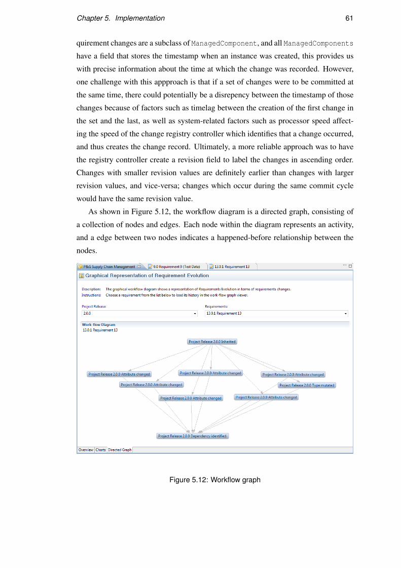
Chapter 5. Implementation 61
quirement changes are a subclass of ManagedComponent, and all ManagedComponents
have a field that stores the timestamp when an instance was created, this provides us
with precise information about the time at which the change was recorded. However,
one challenge with this appproach is that if a set of changes were to be committed at
the same time, there could potentially be a disrepency between the timestamp of those
changes because of factors such as timelag between the creation of the first change in
the set and the last, as well as system-related factors such as processor speed affect-
ing the speed of the change registry controller which identifies that a change occurred,
and thus creates the change record. Ultimately, a more reliable approach was to have
the registry controller create a revision field to label the changes in ascending order.
Changes with smaller revision values are definitely earlier than changes with larger
revision values, and vice-versa; changes which occur during the same commit cycle
would have the same revision value.
As shown in Figure 5.12, the workflow diagram is a directed graph, consisting of
a collection of nodes and edges. Each node within the diagram represents an activity,
and a edge between two nodes indicates a happened-before relationship between the
nodes.
Figure 5.12: Workflow graph

Chapter 5. Implementation 62
In order to visually render the graph, the Eclipse workbench needed to be extended
by installing the Eclipse Graphical Editing Framework (GEF). GEF provides a toolkit
called Zest for building graphs programmatically. Zest is based on JFace, and provides
a GraphViewer class that functions on the same principles as the text-based JFace
viewer classes. To build the graph, we create the GraphEdge class to provide input to
the GraphViewer as a set of source and destination nodes.
To identify the nodes and edges from a list of requirement changes, the program
first has to sort the list in the correct order using the revision value recorded in each
change (as explained above); the list is iterated and each requirement change is placed
into a bucket according to its revision value. One may choose to build the graph back-
wards, that is by starting from the latest requirement change and working backwards
towards the earliest requirement change recorded, or forward by starting at the earliest
requirement change. In this instance, we chose to build the graph forward, simply for
the sake of clarity in the next step. Having sorted the changes into buckets, we then
proceed to iterate through each bucket in sequence - starting from the smallest revision
number and then proceeding to the second smallest and so on. For each requirement,r
with a revision number x, within a bucket, we create n GraphEdge objects which have
r as its source. n is the number of changes in the bucket with the revision number x+1.
The destination for each graph edge is a requirement contained within bucket x+1.
The final collection of all graph edges is used as input to the GraphViewer instance
created, using a custom StructuredContentProvider and LabelProvider to draw
the final graph. The labels for each node indicate the type of requirement change that
occurred; as mentioned in Section 5.3.4, requirement change type is determined at run-
time based on a set of rules rather than being defined statically for greater flexibility.
5.4.3 Charts
There are limited options in terms of free, open-source charting libraries in Java which
do not require additional application server installation to run. As one of the design
objectives was to create an Eclipse plugin that was light-weight without requiring ad-
ditional server software to be installed, we did not consider using hybrid solutions
such as building Macromedia Flash-based charts to be displayed in a embedded web
browser. The predominant options for coding charts are the Business Intelligence Re-
porting Tool (BIRT)1, and JFreeChart2 libraries.
1http://www.eclipse.org/birt/phoenix/2http://sourceforge.net/projects/jfreechart/

Chapter 5. Implementation 63
BIRT is comprised of multiple modules which can be used for creating reports
and forms from structured data sources such as databases and object-oriented mod-
els. It is the more powerful of the two optons considered, as its usage extends beyond
just charting. However, the biggest shortcoming found while prototyping using BIRT
was that the charts produced are originally intended to be viewed in a browswer en-
vironment, rather than within the Eclipse workbench. This can be overcome by using
the browser widget provided in the SWT library, which uses a predetermined HTML
browser on the platform which Eclipse is deployed (Internet Explorer on Windows,
Mozilla on Linux, Safari on Mac). This raises two issues: firstly, there is the possi-
bility that the browser widget fails to load because of platform-related issues such as
missing browsers (there do not seem to be options to change the browser used). In fact
it is generally recommended that the programmer create an alternate presentation to
the browser widget in the form of a standard SWT-based interface because the browser
widget may fail to load correctly. Secondly, creating the charts in a browser widget
restricts the placement of other widgets around the charts to allow the user a degree of
control over the data being displayed.
JFreeChart is a popular charting library built on top of the Java Abstract Windowing
Toolkit (AWT) by Sun Microsystems. Unlike the SWT library used throughout Eclipse
and by this project, AWT suffers from performance penalties as AWT widgets do not
use native platform widgets but rather use a standard set of widgets created by Sun
which are used across all platforms. One observation when viewing the charts within
this project was that the chart pages felt more ”heavy” in terms of page responsiveness
and loading times. A second, less major, drawback is that SWT-based implementations
have a native application look-and-feel, while AWT ones tend to look more out-of-
place. There are documented techniques for using AWT graphical components within
SWT containers. For our implementation of the charts, the approach taken was to
create a AWT panel hosted in a SWT composite box, and then render all the charts
within the AWT panel.
One additional step needed to use JFreeChart from within an Eclipse plug-in is that
the JFreeChart library needs to be packaged and built as an Eclipse plug-in as well
before the functions can be accessed. This additional step, while straight-forward to
implement, also creates an additional plug-in component that needs to be packaged
together with the plug-in from this project, which creates a minor software distribution
issue. However, the JFreeChart plugin created is relatively small in size, and is much
easier than having to install additional components such as application servers.

Chapter 5. Implementation 64
5.4.4 Plotting the charts
To build a chart, we first define a DataSet for the chart. A DataSet essentially stores
the point to be plotted onto the chart as a set of 3-tuples: (value, metric, project re-
lease). Each chart has at least one dataset object associated with it. This dataset is used
to provide individual data points to draw the chart. Chart features such as the chart ren-
derer, the domain and range axis, tooltips are associated with each dataset, i.e. there
is one renderer for each dataset etc. This provides flexibility in terms of presentation
options, as it is possible to programmatically change the way charts are rendered.
Recall the metrics for a project presented in Section 2.3. The metrics are calculated
as follows:
1. Total number of requirements, RT . This is obtained from the Project instance,
which determines the number of requirement elements that it holds.
2. Total number of requirement changes, RC. This is obtained from the ProjectHis-
tory instance, which determines the number of changes that it holds.
3. Cumulative number of requirement changes CRC, which is calculated by tallying
the number of changes in all the releases leading up to the current release.
4. Average number of requirement changes ARC, which is the calculated by the
formula
ARC =CRC
nwhere n is the number of releases for the given project. The number of releases
is obtained by determining the number of predecessors of the project
5. Requirement Maturity Index RMI, which is calculated by the formula
RMI =RT −RC
RT
6. Requirement Stability Index RSI, which is calculated by the formula
RSI =RT −CRC
RT
7. Historical Requirement Maturity Index HRMI, which is calculated by the for-
mula
HRMI =RT −ARC
RT

Chapter 5. Implementation 65
Once the numbers have been obtained from the relevant object class, we can then
calculate the metric values for each release, and then place them into the proper datasets.
There are two datasets used for displaying the chart in Figure 5.13 - one for storing the
values which tend to have a higher range, which are the RT , RC, ARC, CRC, and a sec-
ond set for storing the three index scores which tend to range in the low single-digits
and may even be negatives.
Figure 5.13: Chart visualization
5.4.5 Dependency graph
Visual presentation of requirement dependencies provides a powerful visual clues on
the relationships between different requirements. Traceability link relationships are
stored in the form of a set of forward dependencies and a set of backward dependencies

Chapter 5. Implementation 66
by the traceability controller (Section 5.3.5). We present this information by creating
an editor page listing both set of dependencies. By combining the two sets of data,
and then using the Eclipse GEF Zest library, we can easily build a directed graph to
illustrate these dependency relationships.
Unlike building the workflow diagram, building a dependency diagram is relatively
straight-forward as traceability links are inherently a set of source and destination
nodes. The important thing to account for is the direction of the relationship, since
a dependency may be a forward or backward dependency - Requirement A has a for-
ward dependency relationship with Requirement B if B depends on A, and vice versa
for backward dependency relationships.
Figure 5.14: Dependency graph
5.5 Testing activities
We focused our testing efforts into evaluating the following aspects of the project: the
quality of the code, the usability of the GUI, and the completeness of functionality. In
this section, we shall discuss code and GUI testing activities, whereas we investigate

Chapter 5. Implementation 67
the functionality of the software and discuss post-evaluation improvements made in
Chapter 6.
5.5.1 Unit testing
The code written was verified through unit tests. However, unit testing activity was
not as extensive as previous projects we have worked as the majority of the code was
either GUI code, or dependant on interactions within the GUI code, both of which
require more specific testing techniques and tools, and more extensive effort to test
than unit tests.
We used a specifications-based approach for writing our tests specifications, and
implemented these tests in JUnit. To limit the number of potential test cases needed,
we used a statement coverage strategy, that is we measured test coverage by the number
of lines of code exercised by the test suite. We focused our unit tests on the plain Java
(POJO) classes which provide the implementation for the models and controllers.
5.5.1.1 Unit testing plug-in code
Eclipse provides out-of-the-box support for standard JUnit. However, testing plug-
in code in normal JUnit produces errors because JUnit uses a TestRunner class for
executing the test code, and does not run within the workbench environment. The
PDE (Plug-in Development Environment) JUnit plug-in is required to create a special
TestRunner instance which supports plug-in testing. In order to test the plug-in code,
we create a new plug-in project which has a dependency on both the org.junit4 plug-
in and our original plug-in (uk.ac.ed.inf.requirement.evolution). We separate
the tests from the actual code because adding dependencies to a plug-in means that the
dependencies must be installed in order for the plug-in to run. If we were to embed the
test code into our plug-in, then we would also need to include a copy of JUnit when
distributing the final end product. JUnit is not needed for proper functioning of the
production code, therefore we created a separate test harness plug-in to drive our test
cases.
The test specifications for each class are derived using a specifications-based (black-
box) approach. We assume that the source code is not available; therefore, the test
cases are written based on the specification of each class and its functions. For each
function, we examine the inputs and expected outputs to identify valid and invalid test
values for our test cases. The benefit of not testing against code is that it allows us to

Chapter 5. Implementation 68
concentrate on testing the behavior of the class, and even write the test cases before the
code is implemented, thereby enabling us to adopt a test-driven development approach.
In order to gauge the effectiveness of our test cases, we used the EclEmma Eclipse
plug-in, which allows us to measure our test coverage. The tool provides analysis
capabilities, which were helpful in identifying areas where test coverage was below
par. Figure 5.15 shows the combination of EclEmma and JUnit used for our unit-
testing activities, loaded in the Eclipse.
Figure 5.15: A test case in PDE JUnit with statement coverage analysis from EclEmma
For our project, we set ourselves a goal of achieving at least 80% statement cover-
age in the non-GUI classes, that is ensuring that 80% or more of all executable state-
ments within our POJO code are exercised by the test suite. Figure 5.16 shows a
screenshot of our code coverage as determined by EclEmma.

Chapter 5. Implementation 69
Figure 5.16: Overall test coverage for the project
Before dwelving into the details, the test suite only achieves 15-16% code cover-
age - just over 4200 lines are being executed out of the 27000 or so total lines of code
written in our program. However, bearing in mind that our unit testing is only focused
on POJO code, we should drill-down the overall score and focus on the coverage for
the controller, model.requirement, model.change, model.traeability, and
utils packages. In all of these packages, our test suite achieved at least 80% or
higher coverage, with the exception of the controller package achieving less than
60%. Figure 5.17 provides further details about the test coverage for the classes within
the controller package.

Chapter 5. Implementation 70
Figure 5.17: Test coverage for the controller package
If we examine the code for the controller classes which report low test cover-
age, we discover that there are private methods as well as minor segments which invoke
GUI code which are not tested. For some of the methods, it is almost impossible to
unit test; for instance, a majority of the untested code within the plugin controller class
(ReqEvoPlugin) are methods for creating the image registry, loading image descrip-
tors, and returning the correct image from the registry. Aside from the controller
package, all other POJO classes within the packages report a high-level of coverage, as
shown in Figure 5.18. If we ignored the statements within the GUI-related classes, our
test suite actually tests 3162 statements out of a total of 4327, which is 73% coverage.
Unfortunately, this is still short of our 80% target. It is debatable whether creating
additional test cases to exercise the code in the other packages would raise the quality
of the code as the other code are not directly related to system functionality.

Chapter 5. Implementation 71
Figure 5.18: Test coverage for the model and util packages
There is a caveat in our unit-testing approach: statement coverage is insensitive
to code branches. While statement coverage provides an indication of which lines of
code have been tested, it does not provide an indication of whether all branches in
the code (such as if statements) have been taken by the test suite, or whether loops
are properly terminated (one can only determine whether a loop has been executed
in statement coverage, but not the number of loops etc). There are other coverage
strategies that are more comprehensive than statement coverage. However, we made a
conscious decision to use statement coverage because of the availability of tool support
for quickly evaluating statement coverage.
5.5.2 GUI testing
GUI testing of this software was difficult at best, and tedious at worst. Unlike unit tests,
we could not write test code as most of the issues to be tested involved issues such as
layout and positioning, correctness of the visualizations, legibility of text, sequencing

Chapter 5. Implementation 72
of events, context-sensitive changes to GUI widgets, window focus etc. Programmati-
cally testing for graphical issues is limited; in our project, we almost exclusively used
the traditional ‘eyeball’ method of testing.
While we considered using GUI testing tools, such as Abbott, which allow the
developer to use record and playback mechanisms to test whether outputs meet ex-
pectactions, ultimately we did the GUI tests manually. Part of the reason was that we
used a rapid development approach for building the GUI code – typically, we begin by
writing the code for a page and containers within the page, then add the appropriate
widgets to each container, then the widget listeners, and then testing the interactions
between widgets and pages. At each step, we determine whether layout, positioning,
size, and color in the end-product was correct, and then only incrementally adding new
components to the code. In most cases, each code-test cycle lasted between five to ten
minutes; recording the playback scripts for each incremental build would have easily
doubled the time taken when visually identifying the problem and fixing it would have
been relatively trivial.
The most effort in GUI testing was spent troubleshooting the issues found. While
simple bugs (those which were present in a single page) were relatively easy to trou-
bleshoot and fix, complex ones were more difficult. Show-stopping bugs often in-
volved interactions between different components or was the culmination of a long
of sequence of events. When those happened, we would have to resort to piece-meal
testing of all the participant classes.
In later stages of development, a tool-based approach would have been preferred
over the eyeball method. In particular, when testing event-driven sequences in the
GUI, a manual method proved to be tedious and at times ineffective. Given that there
is a large range of actions which the user can take in the workbench, there were many
test combinations that needed to be tested. Repetitious testing meant that tired eyes
could potentially overlook minor flaws. In subsequent releases and future extensions,
we would give serious consideration to automating a large portion of the GUI tests for
regression testing purposes.
5.6 Summary
In this chapter, we have discussed the implementation of the software tool, includ-
ing the various controllers used as intermediaries between the models and the views.
In designing and implementating the GUI components within Eclipse, we have taken

Chapter 5. Implementation 73
into consideration issues such as Eclipse usability guidelines. We have also presented
our design decisions to justify certain implementations. In discussing implementations
of the visualizations, we presented information about how the visualizations are pro-
grammed, and how the data source for the visualizations are extracted. Finally, we
finished the chapter with a discussion on the code testing activities conducted, and the
difficulties of GUI testing.

Chapter 6
Post-implementation Evaluation
Up to this point, we have delved into the details of how our tool was designed, im-
plemented and tested. In the preceding chapter, we have concentrated our efforts on
testing the quality of our code, and the usability of the GUI. In this chapter, we will
evaluate the functionality of the tool. We will evaluate our tool against the criteria
identified in Chapter 3. Furthermore, we will use our tool to implement various models
that have been proposed for studying requirements evolution drawn. These models are
drawn from the previous work we reviewed in Chapter 2. Finally, we close the chapter
by addressing the shortcomings found, and describing the areas of improvement which
we have made to the tool.
6.1 Functional evaluation
Recall the evaluation criteria we proposed in Section 3.1.1. In the criteria, we identified
desirable functions and system properties which should be supported by requirements
management tools in general. We apply the same criteria in our review of our tool to
identify the limitations of our project. Even though the initial evaluation exercise was
treated as a design activity to determine the requirements expected of our final tool,
we expect that we will not fulfill all of the evaluation criteria. The objective of this
project was not to build a better requirements management tool, but rather to provide
one that provides the ability to analyze requirements evolution within conventional
requirements engineering processes.
74

Chapter 6. Post-implementation Evaluation 75
6.1.1 Requirements elicitation
Firstly, we evaluate the tool’s support for requirements elicitation activities, that is
the collection of requirements. Requirements engineering best practice dictates that
requirements should be documented in a standard template. In our tool, this is achieved
by the use of the modified Eclipse editor which provides the user with a requirements
specification format. We further assist the user in adhering to other guidelines, such as
ensuring the uniqueness of tags used to identify requirements.
Requirements elicitation may also be in the form of integrating existing require-
ments into a project. In functional terms, the tool should provide import capabilities to
allow the user to extract information from external structured and unstructured sources.
This is not implemented in our tool, as we are focused on downstream activities such
as managing and analyzing requirements and changes. However, the current system
currently stores and loads project data into and out of XML. We believe that integrat-
ing our tool with structured data sources which support exporting of data to XML is
possible, and suggest this is an area which merits further work.
Sommerville et al suggested that there are four aspects to a requirement which are
of interest: identification, intrinsic properties, source, and elaboration (Sommerville
and Sawyer, 1997). Our tool only captures three out of these four aspects. Source
information, which provides information about the ownership, origin and stakeholders
of those requirements, is not captured in our tool. We recognize that all four aspects are
equally important in the software development process; however, we omitted source
properties due to time concerns in implementing a module for managing project par-
ticipants. If we had included source information in our requirement model, then we
would have been able to support capture of changes in requirements ownership.
Table 6.1 summarises the functions implemented in our tool for supporting require-
ments elicitation activities

Chapter 6. Post-implementation Evaluation 76
Table 6.1: Evaluating requirements elicitation functionality
Criteria Response(Yes/No)
1. Requirements Elicitation
1.1 Requirement documentation
1.1.1 Provides standard specification template for documenting requirements Yes
1.1.2 Provides editor support for modifying requirements Yes
1.1.3 Captures requirement identification properties Yes
1.1.4 Captures requirement intrinsic properties Yes
1.1.5 Captures requirement elaboration information Yes
1.1.6 Captures requirement source information No
1.2 Import from unstructured data source No
1.3 Import from structured data source No
6.1.2 Requirements management
Requirements management tools are so called because they are intended to provide
requirement engineers with tool support in their jobs. As opposed to word processors
or spreadsheets, specialised tools automate or make it easier for the engineer to create,
read, update and delete requirements in a structured manner. Ideally, the tool should
allow the engineer to specify dependency links between requirements, review changes,
as well as analyze and measure the state of the requirements as a whole. Our tool
provides all of the aforementioned functions, and provides additional functions such
as creating new releases from existing projects.
Table 6.2 summarises the functions implemented in our tool for supporting require-
ments management activities.

Chapter 6. Post-implementation Evaluation 77
Table 6.2: Evaluating requirements management functionality
Criteria Response(Yes/No)
2. Requirements Management
2.1 Presents overall project structure Yes
2.2 Allows creation, read, update, and deletion of project elements Yes
2.3 Traceability support
2.3.1 Automated identification of requirement dependencies No
2.3.2 Allows manual editing of requirement dependencies Yes
2.3.3 Identifies forward and backward dependencies Yes
2.3.4 Detects cycles in requirement dependencies No
2.3.5 Detects requirement conflicts No
2.3.6 Performs impact analysis on requirement creation, update and deletion No
2.3.7 Provides support for manually tracing dependencies Yes
2.3.8 Creates traceability links to external artifacts No
6.1.3 Change control
We identified that a version control mechanism is integral in a requirements manage-
ment tool due to the high-rate at which requirements may change. If the tool tracks
changes, we can then build a change history of the requirement and ultimately, the evo-
lution of that requirement. However, in order for this change history to be meaningful,
the change recorded should encompass aspects of the system, the requirement, and the
environment. We are also not just concerned with changes in the content of the require-
ment, but also in the properties of the requirement, its relationship with its environment
(i.e. other requirements, and the project), as well as the state of the requirement.
Change control functionality in conventional requirements management tool only
track changes in the content. Our tool records changes in all these aspects, as it is
critical to building a meaningful change history and a more complete picture of the
requirement’s evolution. We further complement this capability by providing visual-
izations of the changes, as discussed in the section below.
One additional capability which we provide is the option to create new projects
based on existing ones, allowing the user to inherit requirements from other projects as
they see fit. At the moment, further work is needed to improve this aspect of the tool
as this feature was added as part of the post-implementation improvements identified

Chapter 6. Post-implementation Evaluation 78
(refer to Section 6.3.2).
Table 6.3 summarises the functions implemented in our tool for supporting change
control activities.
Table 6.3: Evaluating change control functionality
Criteria Response(Yes/No)
3. Change Control
3.1 Version control
3.1.1 Manage requirement revisions Yes
3.1.2 Manage requirement variants Yes
3.1.3 Allow merging of requirement variants No
3.1.4 Create new project releases Yes
3.1.5 Create project variants Yes
3.1.6 Allow merging of project variants Yes
3.2 Change history
3.2.1 Captures changes in requirement contents Yes
3.2.2 Captures changes in requirement dependencies Yes
3.2.3 Captures changes in requirement state Yes
3.2.4 Captures changes in requirement environment Yes
3.3 Change information
3.3.1 Captures information about when requirement change occurred Yes
3.3.2 Captures information about where requirement change occurred Yes
3.3.3 Captures information about how requirement changed Yes
3.3.4 Captures information about who changed the requirement No
3.3.5 Captures information about why requirement was changed Yes
3.3.6 Classifies requirement changes for analysis Yes
6.1.4 Analysis
In analysing requirements, the software used should provide the engineer with informa-
tion to determine the health and state of the requirements. Healthiness of the require-
ments refers to the maturity or stability level of the requirements, which is measurable
using standardized metrics such as the RMI and RSI. It should provide visualization
support to intuitively identify patterns in the maturity of the requirements. The visual-
izations should convey quantitative information (such as the aforementioned RMI and

Chapter 6. Post-implementation Evaluation 79
RSI), as well as provide a graphical representation of different relationships within the
system, such as traceability (dependency) links and change history. Given that the fo-
cus of this project is very much in this area, our tool unsurprisingly supports all of the
above, though we must acknowledge the slight bias in the evaluation criteria in this
respect.
At the moment, we have not implemented report generation functionality within
the tool. This is an area of further work that can be implemented by creating an addi-
tional reports module which can collate the requirements data and visualizations into
a formatted report.
Table 6.4 summarises the functions implemented in our tool for supporting require-
ments analysis.
Table 6.4: Evaluating analysis functionality
Criteria Response(Yes/No)
4. Analysis
4.1 Scores project performance using standard requirement performance met-
rics
Yes
4.2 Visualizations
4.2.1 Generates requirement performance metrics chart Yes
4.2.2 Generates requirement change history visualization Yes
4.2.3 Provide customization of visualizations Partial
4.3 Reports No
6.1.5 Non-functional aspects
In a strict sense, this isn’t an evaluation of the non-functional properties of the require-
ment management tool, but rather gives the reader a view of practical aspects of the
evaluated tool beyond just software functions. We identify the platforms on which
a tool is available to determine deployment options, the development language and
source code to determine the possibility of third-party development, licensing to de-
termine the cost of ownership, and the run-time requirements to determine technical
prerequisites for using the software.
Our tool is implemented as an Eclipse plug-in; as such, it will run on whichever

Chapter 6. Post-implementation Evaluation 80
platforms are supported by Eclipse. It is developed in Java which has a large developer
base, and it is our hope and intention that the code from this project will be open-
sourced. At the very least, it should be made freely available. To use the tool, one
requires a copy of Eclipse (version 3.4 and above), along with several required plug-
ins which can be easily downloaded or distributed along with this tool. Unlike most
requirements management tools, it does not require a relational database and applica-
tion server to be installed.
6.2 Supporting theoretical evolution models
During our investigation into theoretical accounts of requirements evolution, we have
encountered variations in the way requirements evolution is captured, classified, and
presented. Earlier, we stated that one of the motivations for creating this tool was to
provide tool support to spur further research in requirements evolution. To that end,
our tool should provide a high-level of support for different methodologies or models.
In the following sections, we will evaluate our tool against different focus areas of
requirements evolution. The methods or models are drawn from the literature reviewed
in Chapter 2.
6.2.1 Evolution of requirements
Rolland provided a model for understanding the evolution of software artifacts (Rol-
land and Prakash, 1994). In her model, an object’s history is comprised of its inner,
spatial, and temporal histories. Inner history captures changes in the object’s contents;
spatial history captures aspects in the object’s environment which have changed; tem-
poral history captures changes in an object’s relationship with objects from which it is
mutated from. In Figure 6.1, we show how our tool supports all three history types.

Chapter 6. Post-implementation Evaluation 81
Figure 6.1: History types captured in the Requirements Evolution Visualization tool
Our solution supports capture of the three different histories by writing hooks in
our system to capture changes in terms of requirement content and type, requirement
relationships, as well as events in the requirement’s lifecycle (i.e. the creation of a
requirement, inheriting from existing requirements to produce mutations, and the dele-
tion of a requirement). While we do not explicitly classify changes using Rolland’s
definitions, requirement’s complete change history is comprised of all three different
histories.
The limitation of our current design is that we cannot account for changes in the
environment that are external to the system. For instance, Anderson et al consider
changes to encompass events such as hardware modifications, or compliance issues,
while Lamsweerde considers environmental factors such as introduction of new tech-
nology (Anderson and Felici, 2002; van Lamsweerde, 2009). In its current state, such
changes are not visible to the model; hence these changes are only recorded when the
user changes the requirement itself in reaction to those external events.
6.2.2 Evolution types and causes
There is no single standard classification of requirements change - different researchers
have different interpretations of how changes should be classified. Some choose to use
extremely granular classifications while others use broader classifications. In design-
ing our tool, we devised our own classification system based on previous work pre-

Chapter 6. Post-implementation Evaluation 82
sented and our own interpretation of requirement evolution. However, our intention
is to encourage requirements evolution analysis rather than to introduce yet another
classification system. Therefore, our implementation dynamically determines classifi-
cation based on information stored in the change record when the visualization is being
built, rather than to statically classify the change when the change occurs.
We implemented the EvolutionInference controller class as a means for the user
to define his/her own change types. However, we do specify that some change types
are immutable (those that are tied to the requirement’s lifecycle, such as creation, or
changes in dependencies) though these are renameable. We further allow the user
to specify how change types are determined by the system through a rules system in
which the requirement property changed is mapped to a change type.
As an example of how the tool can support current classifications, we apply An-
derson and Felici’s classification (Anderson and Felici, 2002) to our sample set of
data. For the purposes of this example, we take a subset of their classification of
changes: Explanation, Rewording, Traceability, Add, Delete, and Modify. Explanation
and Rewording are applied when the requirements text are elaborated or rephrased for
clarity. Traceability is applied when traceability links are changed. Add, and Delete
correspond to events in the requirement’s lifecycle, while Modify is applied when the
requirement is changed.
Add, Traceability, and Delete changes are what we term as life-cycle change events.
In our tool, the equivalents are Creation, Dependency, and Deletion. The text used for
labeling these changes are defined in the plug-in property file. We can modify the
relevant fields in the property file to match those defined by Anderson et al, or indeed
change types defined in any other classification system. For the other change types,
we define new change types through the evolution customization screen (shown in
Figure 6.2).

Chapter 6. Post-implementation Evaluation 83
Figure 6.2: Creating new change types
Once we have created the change types, we then change the mapping rules used to
classify changes so that the new classifications are used in the change history (shown
in Figure 6.3). Changes in the mapping rules and redefinitions of change types are
reflected in the visualizations, even for existing changes that were recorded prior to the
introduction of the new change types and rules.
Figure 6.3: Mapping change types to requirement changes
Finally, we test that the new change types and rules are picked up by the system by
reviewing the change history table for a requirement, or visual history diagram. Note
that the visualizations are built using the change classifications defined at the time it is
built; therefore, existing visualizations need to be refreshed in order to reflect the latest
changes (to do so, either close the content editor or choose a different requirement
release to visualize from the dropdown menu). Figure 6.4 shows that our new change
types and classification rules are reflected in the system.

Chapter 6. Post-implementation Evaluation 84
Figure 6.4: Effects of classification changes
The exercise we have described above can be easily replicated to tailor our tool to
different classification systems.
6.2.3 Analysis of requirements evolution
In Section 2.3, we reviewed existing methods for analyzing requirements evolution to
identify what visualizations would aid in the analysis. We found that most require-
ments evolution research concentrated analyzing on the evolution process, that is un-
derstanding how requirements evolve over time and over releases. By sorting through
a list of changes manually, the researcher then builds a directed graph of the changes
which provides an illustration of the changes that a requirement has undergone.
van Lamsweerde defines the directed graph depicting requirement changes as the
evolution cycle (van Lamsweerde, 2009). The evolution cycle is drawn as a two-axis
chart, with the x-axis being the time dimension, and the y-axis being the space dimen-
sion. Changes to a requirement within the same release are changes which produce
revisions of the requirement, and are tracked over time. Changes which adapt or ex-
tend a requirement are said to produce variants of the requirement, and are charted on
the y-axis. Figure 6.5 shows an example of van Lamsweerde’s evolution cycle.

Chapter 6. Post-implementation Evaluation 85
Figure 6.5: van Lamweerde’s evolution cycle
The equivalent figure in our tool is shown in Figure 6.5. Our approach is to build
the change history using a tree-like structure, as we consider the change history for
a requirement to be the equivalent of a family-tree - the requirement being analyzed
is the culmination of all the changes that have been made on its predecessors. While
van Lamsweerde uses the terms variants and revisions to distinguish between major
and minor versions of the requirement, we use the the terms releases and revisions
respectively. In our system, requirements produce variants when a requirement is in-
herited in two or more different projects, thereby producing two releases of the same
requirement. We capture information about when a requirement change occurred using
timestamps contained within each node of our graph. Each node are arranged accord-
ing to the order in which they were captured (earliest at the top, latest at the bottom of
the tree).

Chapter 6. Post-implementation Evaluation 86
Figure 6.6: Concept of variants and revisions in our software
Our implementation of the evolution cycle closely mirrors a workflow diagram
used to capture the sequence of requirement changes. The aim of the workflow dia-
gram is to capture the evolution process intuitively as a series of actions or changes.
Felici presented the concept of the requirement change workflow as means of under-
standing the impact of each change (Felici, 2004); as shown in Figure 6.7(a), his work-
flow diagram is shown as a horizontal series of changes that ripple out from a single
change. In our design, we represent changes as a tree structure because we view each
requirement as the resultant effect of a series of changes thus our workflow diagram is
akin to a family tree (e.g Revision B of a requirement is the result of Change A1 and
Change A2). Our workflow diagram is not the equivalent of Felici’s workflow (hence
we term ours as the visual history of a requirement), but both share the similar con-
cept of representing changes as a sequential series of events. Figure 6.7 illustrates this
comparison.

Chapter 6. Post-implementation Evaluation 87
(a) Workflow diagram (b) Visual history visualization
Figure 6.7: Visualizing requirement change histories
Requirements evolution can also be observed through quantitative methods, as de-
scribed in Section 2.3. Prior to our implementation, measurements of a project’s stabil-
ity and maturity (in terms of requirements) would have to be done manually. For each
software release or project, one would need to determine the number of requirements,
changes, and cumulative changes in order to calculate standard index scores such as
RSI, RMI, and HRMI (refer to Section 2.3 for the definitions) and then plot the data in
separate charts. In our tool, these are calculated by the code and presented as charts to
the user. Figure 6.8 provides an illustration of the visualizations produced by our tool
in comparison with visualizations encountered in the literature.

Chapter 6. Post-implementation Evaluation 88
(a) Manual HRMI graph (b) HRMI visualization
(c) Manual change distribution graph (d) Change distribution visualization
Figure 6.8: Requirement evolution metrics
6.3 Improvements
Our improvements are mainly to address flaws in the original design, either in our in-
terpretation of conceptual aspects, general usability issues, or extending existing func-
tionality to provide better support of the theoretical models discussed above. The fol-
lowing is a discussion of significant improvements or responses to the issues identified.
6.3.1 Classification of requirement lifecycle events as requirement
change
One of the test inputs used in post-implementation testing of the software was the
inclusion of projects with multiple releases. In each release, the project had inherited a
number of requirements from a previous release. These were stable requirements that
had not undergone any changes since inception. Based on this fact, the expectation then
is that each subsequent release should have better Requirements Stability Index (RSI)
and Historical Requirements Maturity Index (HRMI) scores than the previous release,

Chapter 6. Post-implementation Evaluation 89
since the number of cumulative changes had remained static even as the number of
releases had increased. Logically, the more releases in which a requirement remains
unchanged, the more stable the requirement becomes. However, the results that were
observed from the software showed that the RSI and HRMI scores remained relatively
constant, or exhibited only slight deviations, which contradicts this logic.
This contradiction can be attributed to our interpretation of requirement changes,
and consequently the way changes are modelled and classified in this system. Recall
from Section 4.3.2 that we proposed that all requirements undergo different types of
changes, the foremost of which is lifecycle changes. We argue that a requirement goes
through different stages in its lifecyle, with each stage having different implications
to the requirement. Recall our definitions of requirement states from Section 4.2.2.2,
in which we stated that requirements which are an offspring of (i.e. inherited from)
another requirement are actually a new variant of the original requirement. The variant
requirement’s environment (its project, and its relationships) are different from the
original, in which case this constitutes a change for the requirement even if the contents
of the requirement may be identical to the original.
Figure 6.9 illustrates the differences between including and excluding inheritance
events as a change type. In the example used for drawing the chart shown, we chose
to create a succession of releases in which little to no requirement changes were made.
The only change records created in the system were created when the project inherited
existing requirements from a previous release. Therefore, the requirements in the last
release are considered to be stable requirements since no modifications have been made
in previous releases. Recall that the Requirement Stability Index, RSI, is calculated by
the formula RSI = RT−CRCRT
, where RT is the total number of requirements in a release,
and CRC is the cumulative total number of requirement changes for the release being
analyzed.
In Figure 6.9(a), we consider inheritance to be a change type - by including in-
heritances, the CRC is observed to be increasing between releases, even though no real
modifications have been made to the contents of the requirements. The result is that the
RSI score is decreasing, indicating that the stability of the requirements is decreasing,
which is not entirely accurate if one does not consider changes in the requirement’s
environment to be a change at all.
In Figure 6.9(b), the chart is built by ignoring inheritance events. The result is that
the CRC for the project remains static through the releases, which in turn translate to
a static RSI as well (in the chart shown, RSI is 0 for all the releases). This provides

Chapter 6. Post-implementation Evaluation 90
a more accurate reflection of the fact that the contents of the requirements have not
actually changed.
(a) Include inheritance change types
(b) Exclude inheritance change types
Figure 6.9: Effect of inheritance change type on project metrics
Ultimately, whether the scores accurately reflected the maturity of the requirement
depends on the individual’s interpretation of what constitutes a change. Therefore,
an additional function was implemented to allow the user to elect whether or not the

Chapter 6. Post-implementation Evaluation 91
system should consider the inheritance lifecycle event as a requirement change when
calculating RSI and HRMI scores.
6.3.2 Multiple inheritance for projects
In our original design, it did not occur to us that projects may be derived from multiple
source projects. We assumed that projects are released in a linear sequence, that is one
after another. In actual fact, project may branch out in different variants due to many
reasons. Each variant of a project is a separate release which may be worked on in
parallel.
Our original object model supports projects having multiple branches. In our orig-
inal design, we determine the lineage of a particular project by referring to the pre-
decessor field of the project class, thereby allowing us to trace a project’s history up
its inheritance tree. In foresight, we used a linked list for the predecessor field, hence
modifications only needed to be made to the GUI code to allow users to select which
projects a new release would be derived from.
Figure 6.10: Visualizing a project inheritance tree
With the new possibility of projects having multiple predecessors, it then made

Chapter 6. Post-implementation Evaluation 92
sense to provide a visualization that graphically represents the inheritance tree. We
implement this visualization (shown in Figure 6.10) using a directed graph build from
the algorithm described in Section 5.4.2.
6.3.2.1 Merging different releases of the same project
One challenge in allowing multiple inheritance for projects was the issue of multi-
ple releases of the same project. In our model, different project releases are different
instances of the same project. Therefore, theoretically our model allows for the prede-
cessors of a project to be different releases of the same project.
From a practical point of view however, we are concerned with the changes that
have been made in the requirements of different releases, particularly if those releases
are being modified in parallel. Which version of the requirement would the new project
inherit? We attempt a workaround to this issue by providing information such as the
timestamp and revision number to the user, and then forcing the user to choose only
one if such a conflict exists, as shown in Figure 6.11.
Figure 6.11: Detecting requirement variants
A more complicated scenario would be if requirements in each of the different re-
leases are actually heavily modified variations of the same requirement, and the user
is unaware of this branching. In fact, due to gradual changes over time, the different
variants may share no commonality aside from the fact that they are different interpre-
tations of the same requirement. In such a scenario, the system needs to be aware of the
conflict so that the user is aware as well. From a technical viewpoint, our requirements

Chapter 6. Post-implementation Evaluation 93
model allows us to identify common ancestors in different requirements. In our imple-
mentation, requirements are identified by a unique identifier, a project identifier which
associates the requirement with a project, and identification properties (requirement
tag, and name). Variants of the same requirement have different project identifiers and
identification properties, but the unique identifier remains the same (to digress, for re-
visions of the same requirement, all these properties are the same, with the exception
of the requirement revision number). Therefore, in the case of merging different re-
quirements from different projects, we actually ignore all other requirement properties
except the unique identifier, which allows us to identify ’identical’ requirements.
There are limitations to such an approach. We do not take into account more com-
plicated issues such as conflicts and dependencies. Future revisions to the code should
consider issues such as missing dependencies, and conflicting requirements (e.g. re-
quirement A requires that X is met, but requirement B requires that X is not met). This
is a complex subject which requires further study beyond the limits of this section.
6.3.2.2 Ordering change histories from multiple predecessor projects
When building visualizations such as the directed graphs and charts, the sequence in
which changes are presented depends on the ordering of the predecessors as identi-
fied by the algorithm. With multiple branching, this becomes impossible to determine
without the use of timing mechanisms such as logical clocks. Our algorithm works for
nodes in the same branch, and the trunk of the inheritance tree. However, we are un-
able to reliably determine the ordering of the branch nodes since we cannot determine
a happened-before relationship between nodes in different branches.
Figure 6.12 illustrates the difficulties in determining the ordering of the branch
nodes. In the example shown in the figure, we attempt to build a complete history of
node C, beginning from the original project, node 1. From the ordering, we can only
definitively say that node 1 happens before node 2, node 2 happens before node A1 and
node B1, node A1 happens before node A2, and that node A2 and node B1 happens
before node C. However, we are unable to determine whether node B1 happens before
any of the nodes in the top branch. This affects the way the change history is build, as
changes in one branch may interleave with changes in another. Consequently, allowing
multiple inheritance also compromises the correctness of the visualizations.

Chapter 6. Post-implementation Evaluation 94
Figure 6.12: Determining ordering in different release branches
The interim workaround we have implemented is to use the order in which the pre-
decessors of a project are returned when queried. The current ordering is the order in
which predecessors are added to the list, which does not reflect the actual ordering. Al-
ternatively, we can use the createdOn timestamp contained in each Project instance to
determine the ordering in which the projects were created. This method works within
the current single-user implementation; however, a distributed multi-user implementa-
tion of the tool would have to account for clock differences in individual machines.
6.3.3 Complete visual histories of requirements
Initial feedback of the visual workflow diagram, which is a graphical representation
of a requirement’s change history, indicated that the usefulness of the diagram was
limited if the graphs presented were limited to showing changes within a single release.
In particular, as the number of software releases increased, it became more important
to be able to backtrack up along the branches of the history tree to certain key events
that occurred in earlier releases.
The intial algorithm used for constructing the workflow diagram, as explained in
Section 5.4.2 built graphs based on the changes within a single release. The algorithm
was adapted to recursively build workflow graphs for a requirement starting from the
latest release back to the initial point of creation. A full history of a requirement can be
easily retrieved as the requirement’s parent project maintains a list of IDs which point
to its predecessors (other projects). The change registry maintains a project history
repository for each individual projects, from which we can retrieve a set of recorded
changes for the given requirement.
Adapting the algorithm to build the graphs resulted in the creation of multiple
graphs within the graph container. For instance, if a requirement has changes over

Chapter 6. Post-implementation Evaluation 95
three releases, the algorithm would draw three separate graphs - one for each release.
However, we can build edges between these graphs to show the correct sequence.
First we determine the earliest nodes (termed as first nodes) in a given release, and
then identify the latest set of nodes (termed as last nodes) in the release immediately
preceding the one we are working on. We then create edges with the last nodes as
the source, and the first nodes as the destination. The result is the graph shown in
Figure 6.13.
Figure 6.13: Visual history illustrating changes over the lifetime of a requirement
6.4 Summary
In this chapter, we have evaluated our software tool against the criteria we used to
evaluate other readily available tools. We also discussed shortcomings of our initial
implementation, and presented improvements. While the software tool may not be
perfect, it is hoped that these improvements will increase the functionality and usability
of the tool as a whole.

Chapter 7
Conclusions
Over the course of this project, we have analyzed work that has been done in the
field of requirements engineering in terms of theoretical research as well as practical
accounts in terms of software implementations. We have found that requirements evo-
lution analysis is an emerging field of research, with applications beyond just decision
support for development activities, but also for understanding software development
patterns in terms of requirements progression. However, the tool support for analyzing
requirements evolution has thus far been non-existent. As such, we hope that the resul-
tant software tool developed for this purpose will fill this gap, and contribute towards
building a larger body of work in our understanding of requirements engineering.
In this chapter, we will present the outcomes, challenges and lessons we have learnt
from this project. We then end by suggesting extensions which we feel would either
bring our tool up to par with many commercial implementations, or provide a paradigm
shift in how practitioners approach requirements engineering which have been dis-
cussed in theory but yet to be widely implemented in practice.
7.1 Outcomes
At the beginning of this project, we identified that the central hypothesis for this project
was that existing requirements engineering methods, tools and models can be extended
to capture requirements evolution (defined as hypothesis H1 in Section 1.2). We have
used Lorman’s existing requirements management system architectural model, in com-
bination with existing methods for studying requirements evolution, to create a tool that
supports the requirements engineering process while enabling us to capture and visu-
alize requirements evolution data. In Chapter 2, we looked at the methods and mod-
96
Chapter 7. Conclusions 97
els that have been proposed for capturing and analyzing requirements evolution. We
found that existing techniques focus on different aspects of the requirements evolution
problem; our work attempts to build a more holistic view of requirements evolution.
Our interpretation of, and solution to, the various aspects of requiements evolution
wwas presented in Chapter 4 as a functional design that takes into account previous
work in the field. In particular, we were inspired by the work presented by Rolland
on software artifact evolution (Rolland and Prakash, 1994) to understand the context
in which requirements evolve and the importance of capturing the context as well as
the change itself; van Lamsweerde’s work to understand that requirement evolution
occurs in two dimensions (time and space) as a means of understanding the dynamics
between requirements evolution and the software development life-cycle (van Lam-
sweerde, 2009); and the works of Anderson and Felici as a means to extract evolution
data and visualizing the outcomes for analysis (Anderson and Felici, 2002).
Recall from Section 1.2 that we also proposed two additional hypotheses: H2,
which states that analyzing requirements evolution enhances our understanding of
how software requirements evolve over time within a single project and over multi-
ple project variants, and H3, which states that the requirements evolution of a system
reveals characteristics of the underlying organizational and development processes.
We were unable to analyze the requirements evolution data as a means of understand-
ing the interrelationship between requirements evolution and software evolution. The
data we used in our testing and evaluation were limited in scope and complexity. Ide-
ally, we would have used industrial case studies as input for our tool, thus enabling
us to study the effects of requirements evolution on different system properties – for
instance, the relationship between requirements stability and development methodol-
ogy (e.g. do different methodologies cope with changes better, and at what stage of the
process can requirements change without having a negative impact on project timelines
and effort). Regretably, we are unable claim to have accomplished hypothesis H2 or
hypothesis H3, although we are confident that given the time and case study, both of
these could have been accomplished.
Ultimately, we have created an Eclipse plug-in for managing requirements that
enables the capture of requirement changes in a way that differs from conventional
requirements management tools. We have developed one of the few requirements
management plug-ins for the Eclipse platform. We believe that the requirements and
change model we have designed, and the implemented plug-in is flexible enough that
further modification of the code can be done with relative ease.

Chapter 7. Conclusions 98
7.2 Challenges
We began this project with limited knowledge about the field of requirements engineer-
ing. Without the background knowledge of requirements engineering practices, pro-
cesses and terminologies, it was difficult to comprehend the concept of requirements
evolution, much less the manner in which requirements evolution could be captured
visually. The literature review and evaluation of requirements management tools in
the early phases of the project were absolutely critical in ensuring we understood the
subject matter in enough depth to begin designing a solution.
Developing the system as a Eclipse plug-in was a big step up from developing
traditional Java applications. The implication of the decision to create a Eclipse plug-
in was that we needed to pick-up plug-in development skills within the limited time-
frame of this project. We needed to tackle issues such as inconsistencies between the
models and views, data flow and interaction between different GUI components, life-
cycle and resource management of the plug-in. The Eclipse Javadocs were very helpful
in building the basic Eclipse GUI components, as well as understanding the messaging
infrastructure for linking the different view parts. However, help resources on Eclipse
GUI development are relatively limited, not strictly in the sense that there is a lack of
information, but that more often than not, we needed to dwelve into the Eclipse IDE
source code, Eclipse.org message boards, and unindexed sources of information such
as EclipseCon presentation archives to understand some of the advanced functions.
In terms of programming, the literature sources we used proved to be a mixed-bag
as most were written based on versions of Eclipse prior to version 3.4 (which we used).
In some cases, such as the Eclipse plug-in development book written by Clayberg et al,
it was based on Eclipse 3.0 which makes it five generations behind the latest version;
many of the advanced functions we leveraged on were inluded in later releases of the
Eclipse API and less well documented.
Manual GUI development and testing proved to be time-consuming and tedious.
Unfortunately, we could not find a visual WYIWYG editor for building the GUI. Ev-
ery line of the GUI code had to be written by hand, and ultimately tested using a
‘eyeball’ testing method. This was further complicated by the fact that the graphical
components were written using several different libraries (AWT, GEF, SWT, JFace,
Eclipse Forms, Eclipse UI, JFreeChart), often in tandem with one another. More often
than not, issues arose when integrating different components written using different
APIs. Troubleshooting GUI issues, particularly obscure ones, was overwhelming at

Chapter 7. Conclusions 99
times. Ultimately, GUI programming proved to be the biggest challenge, particularly
given that this is the first GUI-intensive tool we have written.
7.3 Lessons learned
Perhaps the most valuable lesson to take-away from this project is a greater apprecia-
tion of the value of the unseen aspects of software projects. Throughout this project,
we have read numerous published accounts of how requirements maturity provides a
measureable index of the stability of a software release, and ultimately a measure of the
maturity of a software development process. In designing the visualizations, and the
logic behind where the data could be captured or extracted, we gained an insight into
the relationship between requirements and software design. We learnt that software
development cycles often extend beyond just the handful of releases one might work
on within a limited timeframe, and therefore requirement changes and requirement sta-
bility have wide-reaching quality implications on not just a product, but potentially the
entire product family.
From a technical standpoint, we began this project with zero Eclipse plug-in de-
velopment experience. At the end of this project, it is hoped that the effort and time
invested in developing the software has improved our plug-in development skill level.
Working on a mature and professionally designed platform like Eclipse, and often
times having to refer to the source code, has not just improved our programming abil-
ities, but given us exposure to the architecture and design decisions used in industry.
7.4 Future work
This project started out as a software tool for visualizing requirement changes. Along
the way, we have created a requirements management tool for supporting requirement
engineering activities. The following is a summary of our suggestions for further work
to extend the tool. Some of these recommendations fill functionality gaps; one intro-
duces causality analysis of requirement changes; and finally we consider the use of a
viewpoint approach in the requirements engineering process.

Chapter 7. Conclusions 100
7.4.1 Analyzing unstructured requirements
While recommended requirements engineering best practice calls for the use of struc-
tured documents for recording requirements (Sommerville and Sawyer, 1997), un-
structured documents may also be used. However, identifying and classifying require-
ment changes programmatically in unstructured documents is far more difficult. We
would need to first parse the document, identifying sections of text corresponding to
requirements, and then provide a means of importing the text into our tool. This func-
tionality should be created as an additional module that interfaces directly with our
controller classes.
7.4.2 Reports
The tool currently stores requirement, changes and dependencies information in plain
old XML. While the current format is human-readable, business uses would require
proper formatting and presentation. It would be desirable if a module could be written
to format data from created projects into predefined reports. Technologies such as
XSLT already exist to transform XML into ‘pretty print’ documents.
7.4.3 Linkages to external software artifacts
Requirements engineering is often the first of many steps in the software development
process. Artifacts produced during the downstream phases are directly or indirectly
linked to the requirements identified. If the original requirements are changed, or if
new requirements are introduced, the implications of such changes would trickle down
to the relevant software artifact as well. Conversely, the software artifacts produced are
intended to fulfill a certain requirement identified, thus relationships between software
artifacts and the requirements should be recorded as well. This information allows the
software developer to evaluate whether the design fulfills all the requirements identi-
fied. The software extension should trigger alerts when changes are made to either the
requirements, or the software artifact. Unlike other requirements management soft-
ware, this is more easily achievable as the Eclipse IDE can be used to support the
design, implementation, and testing phases of the software development lifecycle.

Chapter 7. Conclusions 101
7.4.4 Causality analysis of requirement change
The current system allows for analysis of requirement changes; understanding the un-
derlying cause for requirement changes adds an extra dimension to the analysis. The
ability to capture change factors and associate these factors to specific points in the
timeline may yield insight into an organization’s development process. For instance,
if there is observed increase in the number of requirement changes during the testing
phase of a project, one might conclude that the requirements engineering process for
the organization is severely lacking, or that changes were being introduced as a result
of changes in the market. On the other hand, causal analysis would assist the engineer
in identifying these external factors which lead to requirement changes, rather than just
changes within the limited context of a requirements management system.
The methods we have investigated during the project have largely focused on cap-
turing, categorising, and quantifying requirement changes. It is a given that require-
ment changes occur as a result of changes in the business environment in which the
system was conceived; the methods implemented do not analyze the chain of changes
which may lead to further changes, or the implications of a new change to the stability
of a software release. Emam et al presented a manual method for tracing requirement
changes to the underlying process and causes (Emam et al., 1997). We propose that
causal analysis functionality should be added to the system in the future, thereby in-
creasing the completeness of the change analysis.
7.4.5 Multi-user environment
The current software tool was designed on the assumption that the system is a single-
user, single instance implementation, much like the Eclipse IDE. However, there are
also Eclipse plug-ins that support collaborative workflows, such as version control
functionality. We acknowledge that requirements engineering is more often than not
a team-based activity, thus functions for supporting collaboration are necessary in an
industrial context.
A multi-user implementation of the system would require the implementation of
a client-server architecture. The existing plug-in constitutes the client component. A
new server component is needed to provide a central repository for the requirement sys-
tem, and the change registry. Users would use the plug-in to interact with the server,
with the ability to check-out and check-in requirements that they wish to work on.
Much like early version control systems, a simple implementation of the server could

Chapter 7. Conclusions 102
support simple locking mechanisms which allow only one user to check-out a particu-
lar requirement. A more advanced implementation would allow concurrent editing of
requirements, and subsequent merging of the different branches.
There are several challenges inherent in having a distributed system. As discussed
in Chapter 5, determining the ordering of requirement changes and project releases
can be a challenge. In particular, the existing implementation makes it difficult to
determine the total ordering of the history of a project which is the combination of
two different projects with two separate histories. The server would likely require the
implementation of a synchronized or logical clock mechanism to tackle this problem.
The multi-user implementation should also support authentication and authoriza-
tion of different users, and assigning different roles to different users. This last point
is particularly pertinent for the implementation of another suggestion, a Viewpoints
approach (refer to Section 7.4.6
7.4.6 Implementation of Requirement Viewpoints
Complex software systems are used by different stakeholders (user groups) who have
different requirements for different parts of the system. Each stakeholder’s viewpoint
of the system is distinctly different, yet requirements are often only captured from
the developer’s viewpoint. This may leave gaps in the system functionality which are
not caught until the system undergoes user-acceptance testing, or worst, after delivery.
The Viewpoints approach presents a method for elicitating requirements that closely
mirrors real-life: a complete set of requirements is produced by amalgamating different
sets of requirements recorded from different viewpoints.
Viewpoints represents a paradigm shift from the more conventional approach adopted
by this project. While traditional requirements engineering methods implicitly recog-
nise the fact that requirements are solicited from different users, Viewpoints models
make this relationship explicit (Sommerville et al., 1998). Viewpoints models should
provide guidance to the analyst on the completeness of the requirements, and allow for
validation of the requirements based on user needs. It is not a simple matter of combin-
ing different sets of requirements to create a master list. Rather, a complete implemen-
tation of the Viewpoints model should take into account issues such as duplications,
overlaps, and conflicts, thus producing a coherent and consistent set of requirements.
A ill-conceived implementation would result in a system with low reusability and co-
hesion at best, and separate systems for each stakeholder at worst.

Chapter 7. Conclusions 103
While adopting a Viewpoints approach for our system may require substantial ef-
fort, viable models for supporting Viewpoints have been proposed in the past and
should form the basis for future implementations (Lormans, 2007; Richards, 2003;
Kovitz, 2003).

Appendix A
Installation
A.1 Pre-requisites
The following is a list of software required in order to use the Requirements Evolution
plug-in.
A.1.1 Project jar files
The following is a list of the jar files that should have been distributed along with the
source code:
1. uk.ac.ed.inf.requirement.evolution 1.0.5.jar which contains the Re-
quirements Evolution plug-in.
2. org.jfree.jfreechart 1.0.13.jar which contains the plug-in version of the
JFreeChart library used for creating the charts.
3. xstream 1.3.1.jar which contains the plug-in version of the XStream library
used for XML serialization.
A.1.2 Eclipse
Eclipse version 3.4 Ganymede is recommended as this plug-in has only been tested on
the aforementioned version, on both the Windows and Linux platform.
Note: Installing the plug-in requires files to be copied to Eclipse’s plugin folder,
thus Eclipse must be installed in your home directory, or a directory in which you have
write access. On DICE, this means that the standard Eclipse installed on lab machines
104

Appendix A. Installation 105
should not be used unless your account has write privileges in /opt/eclipse3.4.
Instead download a copy of Eclipse and extract the file into your home directory.
A.1.2.1 Obtaining Eclipse
1. Go to the Eclipse download page at http://www.eclipse.org/downloads/.
2. Any Eclipse distribution should work, but we recommend using the Eclipse IDE
for Java Developers edition.
3. Eclipse requires an available Java runtime environment in order to run. Eclipse.org
recommends Java 5 JRE.
A.1.3 Eclipse GEF Zest
1. Launch Eclipse (on DICE, use your own copy of Eclipse rather than the one
installed on the lab machines as the subsequent steps are not allowed).
2. In the Eclipse menubar, go to Help –> Software Updates (refer to Figure A.1).
Figure A.1: Updating Eclipse
3. Select Ganymede Update Site.
4. Select Graphical Editors and Frameworks
5. Select the Graphical Editing Framework Zest Visualization Toolkit by tick-
ing the checkbox (refer to Figure A.2).

Appendix A. Installation 106
Figure A.2: Eclipse Software Update dialog
6. Click on the Install button.
7. Eclipse will then determine the requirements and dependencies which need to be
installed along with the GEF Zest toolkit.
8. Review the license agreement and click Accept (only if you accept the terms and
conditions, but note that Zest is needed to run the plug-in!).
9. Once the update has been downloaded and installed. Eclipse will prompt to
restart the workbench. Restart.
A.2 Installation
1. Ensure that pre-requisites are met (refer to Section A.1)
2. Make sure that Eclipse is not running.
3. Copy the project jar files listed in Section A.1.1 into your Eclipse plug-in folder.
(e.g. /home/me/eclipse/plugin, replace /home/me/eclipse with the directory you
installed/extracted Eclipse in).
4. Launch Eclipse.

Appendix A. Installation 107
5. Eclipse will automatically detect the new plug-ins on start-up.
6. If the pre-requisites are met, then you should see that Requirements EvolutionVisualization has been added to the Eclipse menubar (refer to Figure A.3).
Figure A.3: Launching the Requirements Evolution plug-in
7. If not, ensure that the prerequisites have been met, and that you have copied all
the project jar files into the correct Eclipse plug-in folder.

Appendix B
Evaluating Requirements Management
Tools
B.1 Survey questionnaire
The following is a proposed set of criteria for evaluating the functionality of a require-
ments management tool, including support for requirements evolution.
Table B.1: Evaluation criteria for requirements management software
Criteria Response
1. Requirements Elicitation
1.1 Requirement documentation
1.1.1 Provides standard specification template for document-
ing requirements
1.1.2 Provides editor support for modifying requirements
1.1.3 Captures requirement identification properties
(Please elaborate)
1.1.4 Captures requirement intrinsic properties
(Please elaborate)
1.1.5 Captures requirement elaboration information
(Please elaborate)
1.1.6 Captures requirement source information
(Please elaborate)
1.2 Import from unstructured data source
1.2.1 Imports data from unstructured documents.
Continued on next page. . .
108

Appendix B. Evaluating Requirements Management Tools 109
Table B.1 – Continued
Criteria Response
1.2.2 Performs textual analysis to parse document for key-
words to create requirements.
1.2.3 User may manually identify requirements from unstruc-
tured documents.
1.3 Import from structured data source
1.3.1 Imports data from structured data sources with identical
data structure
1.3.2 Imports data from structured data sources with different
data structure
2. Requirements Management
2.1 Presents overall project structure
2.2 Allows creation, read, update, and deletion of project ele-
ments
2.3 Traceability support
2.3.1 Automated identification of requirement dependencies
2.3.2 Allows manual editing of requirement dependencies
2.3.3 Identifies forward and backward dependencies
2.3.4 Detects cycles in requirement dependencies
2.3.5 Detects requirement conflicts
2.3.6 Performs impact analysis on requirement creation, up-
date and deletion
2.3.7 Provides support for manually tracing dependencies
2.3.8 Creates traceability links to external artifacts
3. Change Control
3.1 Version control
3.1.1 Manage requirement revisions
3.1.2 Manage requirement variants
3.1.3 Allow merging of requirement variants
3.1.4 Create new project releases
3.1.5 Create project variants
3.1.6 Allow merging of project variants
3.2 Change history
3.2.1 Captures changes in requirement contents
3.2.2 Captures changes in requirement dependencies
Continued on next page. . .

Appendix B. Evaluating Requirements Management Tools 110
Table B.1 – Continued
Criteria Response
3.2.3 Captures changes in requirement state
3.2.4 Captures changes in requirement environment
3.3 Change information
3.3.1 Captures information about when requirement change
occurred
3.3.2 Captures information about where requirement change
occurred
3.3.3 Captures information about how requirement changed
3.3.4 Captures information about who changed the require-
ment
3.3.5 Captures information about why requirement was
changed
3.3.6 Classifies requirement changes for analysis
4. Analysis
4.1 Scores project performance using standard requirement
performance metrics
4.2 Visualizations
4.2.1 Generates requirement performance metrics chart
4.2.2 Generates requirement change history visualization
4.2.3 Provide customization of visualizations
4.3 Reports
4.3.1 Generates analysis reports
4.3.2 Provide customization of reports

Appendix B. Evaluating Requirements Management Tools 111
B.2 Survey results
Table B.2: Summarised evaluation of requirements management software
Criteria RequisitePro OSRMT JRequisite JFeature
1. Requirements Elicitation
1.1 Requirement documentation
1.1.1 Provides standard specification
template for documenting require-
ments
Yes Yes No No
1.1.2 Provides editor support for
modifying requirements
Yes Yes Partial Partial
1.1.3 Captures requirement identifi-
cation properties
Yes Yes No Yes
1.1.4 Captures requirement intrinsic
properties
Yes Yes No No
1.1.5 Captures requirement elabora-
tion information
Yes Yes No Yes
1.1.6 Captures requirement source
information
Yes Yes No No
1.2 Import from unstructured data
source
Yes No No No
1.3 Import from structured data
source
Yes Yes No Yes
2. Requirements Management
2.1 Presents overall project structure Yes Yes Yes Yes
2.2 Allows creation, read, update,
and deletion of project elements
Yes Yes Yes Yes
2.3 Traceability support Yes Yes No Partial
(requirement-
test case
traceability)
Continued on next page. . .

Appendix B. Evaluating Requirements Management Tools 112
Table B.2 – Continued
Criteria RequisitePro OSRMT JRequisite JFeature
3. Change Control
3.1 Version control
3.2 Change history
3.2.1 Captures changes in require-
ment contents
Yes Yes No No
3.2.2 Captures changes in require-
ment dependencies
Yes Yes No No
3.2.3 Captures changes in require-
ment state
No No No No
3.2.4 Captures changes in require-
ment environment
No No No No
3.3 Change information
3.3.1 Captures information about
when requirement change occurred
Yes Yes No No
3.3.2 Captures information about
where requirement change occurred
Yes Yes No No
3.3.3 Captures information about
how requirement changed
Yes Yes No No
3.3.4 Captures information about
who changed the requirement
Yes Yes No No
3.3.5 Captures information about
why requirement was changed
Yes Yes No No
3.3.6 Classifies requirement changes
for analysis
No No No No
Continued on next page. . .

Appendix B. Evaluating Requirements Management Tools 113
Table B.2 – Continued
Criteria RequisitePro OSRMT JRequisite JFeature
4. Analysis
4.1 Scores project performance using
standard requirement performance
metrics
No No No No
4.2 Visualizations
4.2.1 Generates requirement perfor-
mance metrics chart
No No No No
4.2.2 Generates requirement change
history visualization
No No No No
4.2.3 Provide customization of visu-
alizations
No No No No
4.3 Reports
4.3.1 Generates analysis reports Yes Yes No No
4.3.2 Provide customization of re-
ports
Yes Yes No No

Bibliography
Anderson, S. and Felici, M. (2002). Quantitative aspects of requirements evolution. InProceedings of the 26th Annual International Computer Software and ApplicationConference, COMPSAC 2002, pages 27–32. IEEE Computer Society.
Clayberg, E. and Rubel, D. (2004). Eclipse – Building Commercial Quality Plug-ins.Addison-Wesley.
Emam, K. E., Holtje, D., and Madhavji, N. H. (1997). Causal analysis of the re-quirements change process for a large system. In Proceedings of the InternationalConference on Software Maintenance, page 214. IEEE Computer Society.
Felici, M. (2003). Taxonomy of evolution and dependability. In Proceedings of theSecond International Workshop on Unanticipated Software Evolution, USE 2003,Warsaw, Poland, 5-6 April 2003, pages 95–104.
Felici, M. (2004). Observational Models of Requirements Evolution. PhD thesis,University of Edinburgh. EDI-INF-IP040037.
Gotel, O. C. Z. and Finkelstein, A. C. W. (1994). An analysis of the requirementstraceability problem. In Requirements Engineering, 1994., Proceedings of the FirstInternational Conference on, pages 94–101. IEEE Computer Society.
Harker, S., Eason, K., and Dobson, J. (1993). The change and evolution of require-ments as a challenge to the practice of software engineering. In Requirements Engi-neering, 1993., Proceedings of IEEE International Symposium on, pages 266–272.IEEE Computer Society.
Hayes, J. H., Dekhtyar, A., and Osborne, J. (2003). Improving requirements tracingvia information retrieval. In Proceedings of the International Conference on Re-quirements Engineering (RE), pages 151–161. IEEE Computer Society.
Hull, E., Jackson, K., and Dick, J. (2002). Requirements Engineering. Springer Lon-don.
Jarke, M. (1998). Requirements tracing. Communications of the ACM, 41:32–36.
Kasunic, M. (2008). A data specification for software project performance mea-sures: Results of a collaboration on performance measurement. Technical ReportCMU/SEI-2008-TR-012, Software Engineering Institute, Carnegie-Mellon Univer-sity.
114

Bibliography 115
Kovitz, B. (2003). Viewpoints: Hidden skills that support phased and agile require-ments engineering. Requirements Engineering, 8(2):135–141.
Lam, W. and Loomes, M. (1998). Requirements evolution in the midst of environmen-tal change: A managed approach. In Proceedings of the 2nd Euromicro Conferenceon Software Maintenance and Reengineering (CSMR’98), page 121. IEEE Com-puter Society.
Lormans, M. (2007). Monitoring requirements evolution using views. In Proceed-ings of the 11th European Conference on Software Maintenance and Reengineering,pages 349–352. IEEE Computer Society.
Lormans, M., van Dijk, H., and van Deursen, A. (2004). Managing evolving require-ments in an outsourcing context: An industrial experience report. In Proceedingsof the 7th International Workshop on Principles of Software Evolution (IWPSE04).IEEE Computer Society.
Pinheiro, F. A. C. and Goguen, J. A. (1996). An object-oriented tool for tracing re-quirements. IEEE Software, 13(2):52–64.
Pressman, R. (2005). Software Engineering: A Practitioner’s Approach. McGraw-Hill.
Richards, D. (2003). Merging individual conceptual models of requirements. Require-ments Engineering, 8(4):195–205.
Rolland, C. and Prakash, N. (1994). Tracing the evolution of artifacts. In Databaseand Expert Systems Applications, 5th International Conference, DEXA ’94, Athens,Greece, September 7 - 9, 1994, Proceedings, pages 420–432. Springer London.
Sommerville, I. and Sawyer, P. (1997). Requirements Engineering: A Good PracticeGuide. John Wiley and Sons.
Sommerville, I., Sawyer, P., and Viller, S. (1998). Viewpoints for requirements elici-tation: A practical approach. In Proceedings of the 3rd International Conference onRequirements Engineering: Putting Requirements Engineering to Practice, pages74–81. IEEE Computer Society.
van Lamsweerde, A. (2009). Requirements Engineering - From System Goals to UMLModels to Software Specifications. John Wiley and Sons.