t echnieal roport documenlolion pogo
TRANSCRIPT

T echnieal Roport Documenlolion Pogo
1 .. Report No. 2. Government Aeeession No. 3. Recipient's C:atelog No.
FHWA-TS-88-021
4. Title and Subtitle 5. Report Dote
Long-Term Evaluation of the Acoustic Honitor
Emission Weld February 1988 6. Pl!lrftu·ming Or;onlzation Code
8. Performing Orgoniaotion Report No. '1. Autho~&)
Theodore Hopwood II UKTRP-88-6 9, Performing Orgonhotion Name end Acldreu 10. Work Unit No. (TRAIS)
Kentucky Transportation Research Program College of Engineering 11. Contract or Grant No.
University of Kentucky DTFH61-86-C-00118 Lexington, KY 40506-0043 13. Type of Report ond Period Covered
12. Sp_onsoring Agency Nome ond Adclren Federal Highway Administration Final Office of Implementation September 1986-February 1988 Engineering and Highway Operations 14. Sponsoring Agency CoGe
McLean, Virginia 22101
U. Supplementery Notes
FHWA Contract Manager: Terry D. Halkyard (HRT-10)
16. Abutruct
The Kentucky Transportation Research Program conducted an extended 10-month evaluation of the Acoustic Emission Weld Monitor (AEWM) in a bridge fabrication shop. That device was used to detect welding flaws during typical production of butt-welds on flanges and webs used in steel bridges. A total of 153 welds were monitored.
AEWM test results were compared with visual inspection and double- blind results of conventional nondestructive testing routinely conducted on the welds. The AEWM did not miss any flaws detected visually or by nondestructive testing. Three AEWM flaw indications were confirmed by conventional nondestructive testing (radiography).
A large number of AEWM indications were not related to any detected flaws (228 of 263 indications). Those were attributed to AE noise that occurs away from the weld and small flaws that were either missed or overlooked by visual and nondestructive inspection or were removed prior to inspection by normal fabrication procedures.
The AEWM has shown the sensitivity to detect AWS code-rejectable defects. In part, the high number of overcalls was caused by use of excessive system sensitivity. Due to the success of the unit in detecting flaws, further development is warranted. Specific recommendations for further research are provided.
17. Key Words 18. DisfTibutien Statement
acoustic emission This document is available to the public bridges through the National Technical fabrication Information Service, Springfield, nondestructive testing Virginia 22161 steel welding
19. S.eurity Cloulf. (of thia report) :Ill. Socvrlty Cleulf. (ef thle fllllll@e) 21b No. of P e~ges 22. Price
Unclassified Unclassified 68
"""" DOT f 1700.7 cs-nl

long-Term Evaluation oft he Acoustic Emission Weld Monitor
Report No. FHWA-TS-88-021
Prepared by
Kentucky Transportation Research Program University of Kentucky 533 South Limestone Street Lexington, Kentucky 40506
Prepared lor
Federal Highway Administration U.S. Department of Transportation Washington, D. C. 20590
February 1 988


PREFACE
This study is an investigation of the long-term fabrication shop
performance of the Acoustic Emission Weld Monitor (AEWM) covering field
testing conducted between January and October 1988. The work was performed in
a welding shop that routinely fabricates welded steel bridges for a number of
states.
The study is a continuing research effort that initiated with the
development and laboratory testing of the AEWM by the GARD Division of
Chamberlain Manufacturing Corporation of Niles, Illinois. That work,
sponsored under Federal Highway Administration (FHWA) Contract DTFH61-80-C-
0083, was completed in 1984.
As a follow-up to that effort, the Kentucky Transportation Research
Program (KTRP) conducted a series of demonstrations and a preliminary
evaluation of the unit for the FHWA in 1985. The AEWN was demonstrated to
personnel from 20 state highway agencies representing FHWA Regions 1, 3, 4 and
S. The demonstrations were conducted at three different fabrication shops in
Pennsylvania, Georgia, and Wisconsin.
The AEWM also was used by KTRP to monitor large weldments fabricated for
the Wisconsin Department of Transportation in September 1986. Additionally,
the AEWM has been successfully used to detect fatigue cracks on in-service
steel bridges. An Acoustic Emission Bridge Monitor (AEBH) is presently being
developed by GARD under FHWA Contract DTFH61-86-R-00072 and is to be completed
in October 1988.
This study is sponsored by the Federal Highway Administration, Office of
Implementation. High Steel Structures Incorporated of Lancaster, Pennsylvania
was the host fabrication shop for the AEWM testing. Four state highway
agencies cooperated in this study by allowing welding operations on their
bridge members to be monitored. Those agencies included: New York State
Department of Transportation, Haryland Department of Transportation, Vermont
Agency of Transportation, and New Jersey Department of Transportation. GARD,
a subcontractor to KTRP, provided technical assistance for the AEWM.
v

<: ,...
METRIC (SI*) CONVERSION FACTORS
Sym~
In
It yd ml
In'
ft' yd' mi' ac
0' lb
T
fl Ol
gal
It' yd'
APPROXIMATE CONVERSIONS TO Sl UNITS When You Know
inches feet
yards miles
square inches square feet
square yards square mites
acres
Multiply Sy To Find
LENGTH
2 SA mlllfmelres
0.3048 metres 0.914 metres
~.61 kilometr-es
AREA
645.2
0.0929 0.836 2.59
0.395
mlflfmetres squared metres squared
metres SQuared kilometres squared hectares
MASS (weight)
ounces 28.35 pounds 0.454
short tons (2000 tb) 0.907
fluid ounces gallons
cubic feet
cubic yards
VOLUME
29.57 3.785
0.0328 0.0765
grams kilograms
megagrams
mlltilltres lit res
metres cubed metres cubed
NOTE: Volumes greater than 1000 l shall be shown in m•.
OF
TEMPERATURE (exact)
Fahrenheit temperature
5/9 (after subtracting 32)
Celsius temperature
e Sl is the symbol for the International System of Measurements
Symbol
mm m m km
mm' m' m' km' ha
g
kg
Mg
ml L m' m'
oc
. ~
::;-----:::;:
~
- -'
----
~
~
~
~
~
~
~
! --=
- "
~ ~ ~ ~
~- '!
-
~ ~
~ !
~ :!
~ :::
~ ;::
~ "'
~-----= ...
= ..,
~ : ~ ~
APPROXIMATE CONVERSIONS TO 51 UNITS Symbol When You Know flllultlply By To Find
mm m m
km
mm' m' km' ha
g kg
Mg
ml L m' m'
millimetres
metres
metres kilometres
millimetres squared metres squared
kilometres squared
hectares (10 000 mZ)
LENGTH
0.039 3.28
1.09 0.621
AREA
0.0016 10.764
0.39
2.53
inches feet
yards
miles
square inches
square feet
square miles
acres
MASS (weight)
grams 0.0353 kilograms 2.205
megagrams (1 000 kg) 1.103
millllitres lit res
metres cubed metres cubed
VOLUME
0.034 0.264
35.315
1.308
ounces pounds
short tons
fluid ounces gallons
cubic feet cubic yards
TEMPERATURE (exact)
oc Celsius temperature
915 (then add 32)
Fahrenheit temperature
•F Of 32 98.6 212
-~ ... ? . . [4;'JI 80 ~ .1~. I .160., .2?0J -40 I - 2o I 0 do 4o 6(J
1 6() 100
oc 37 oc
These factors conform to the requirement of FHWA Order 5190.1A.
symbol
;,
11 yd ml
in•
11' mi• ac
0' lb
T
fl Ol
gal
11' yd'
OF

TABLE OF CONTENTS
I. Introduction
II. Operation of the AEWM.
III. Preliminary Study Efforts.
IV.
v.
VI.
Test Objectives Fabrication Shop Selection. AEWM Weld Testing Procedure Project Staffing. Test Equipment.
Fabrication Shop Monitoring.
Test Routine. Progress of AEWM Testing. Weld Procedure Prequalification Test Problems Submerged-Arc Welding and Flaws Role of the Welder in Quality Control Flaws Encountered During Testing.
Data Analyses and Discussion
AEWM Test Results AEWM Flaw Detection Performance AEWM Performance During Shop Testing.
Conclusions.
VII. Recommendations.
Elimination of AEWM False Indications AEWM Reconfiguration. Future AEWM Testing • Future Application of the AEWM.
VIII. Appendix- AEWM Report Form
IX. References •
vii
Page
1
3
7
7 7 8 9
10
13
13 19 20 21 24 24 27
33
33 33 46
47
49
49 49 53 55
57
59
LIST OF FIGURES
Figure
1. Ultrasonic Inspection of Flange Weld •••
2. Use of the AEWM to Inspect Large Weldment
3. AEWM Processing Flow Chart for Flaw Detection
4. Schematic of Typical Butt-Weld Showing Normal Transducer Placement
5. Magnetic Hold-Down Assemblies Housing the Preamplifiers and Transducers • • • • • •
6. Attaching Transducer to Flange Weld
7. Calibrating the AEWM Prior to Monitoring Weld
8. Welder Performing Semi-Automatic Submerged-Arc Weld on 1\Teb.
9. Semi-Automatic Submerged-Arc Welding Gun Depositing "A" Face Weld on Beveled Side of Flange •••••••••••
10. Carbon-Air Arc Backgouging on Back Side of a Flange Weld.
11. Depositing Weld on Flange •
12. Welder Chipping Flux during Welding Operation
13. Grinding a Surface Blemish Prior to Depositing a Succeeding Weld P~ss • . . . . . . • • . • • e
14. Manual Submerged-Arc Weld Repair of Large Weldment.
15. AEWM Flaw Indication from Web Welding Operation ••
16. Slag Stringer (Figure 15) Revealed a£ter Backgouging.
17. Weld "Roll" in Flange Weld. • • • • • • • •
18. Slag Inclusion in Weld (Figure 17) Revealed by Backgouging.
19. Weld Irregularity Caused by Temporary Loss of Flux •••••
Page
2
2
5
. . . . 5
14
14
15
17
17
18
23
23
26
26
28
28
29
29
30
20. Flaw at Weld Termination (Slag and Porosity) Detected by AEWM 30
21. Trapped Surface Weld Slag Detected by AEWM during Root Pass Weld and Subsequently Repaired by Grinding. 31
22. Transducer Assembly Coupled to Weldment • • 52
viii

LIST OF TABLES
Table Page
1. AEWM Fabrication Shop Test Data • . 34
2. Summary of AEWM Testing (Web Welds) 41
3. Summary of AEWM Testing (Flange Welds). 41
4. AEWM Indication Summary (Web Welds) . . 43
5. AEWM Indication Summary (Flange Welds). 44
ix

INTRODUCTION
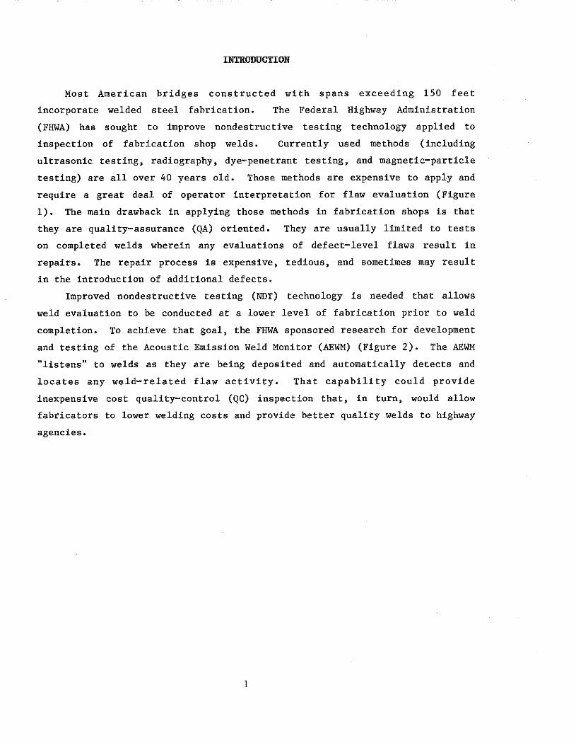
Most American bridges constructed with spans exceeding 150 feet
incorporate welded steel fabrication. The Federal Highway Administration
(FHWA) has sought to improve nondestructive testing technology applied to
inspection of fabrication shop welds. Currently used methods (including
ultrasonic testing, radiography, dye-penetrant testing, and magnetic-particle
testing) are all over 40 years old. Those methods are expensive to apply and
require a great deal of operator interpretation for flaw evaluation (Figure
1). The main drawback in applying those methods in fabrication shops is that
they are quality-assurance (QA) oriented. They are usually limited to tests
on completed welds wherein any evaluations of defect-level flaws result in
repairs. The repair process is expensive, tedious, and sometimes may result
in the introduction of additional defects.
Improved nondestructive testing (NDT) technology is needed that allows
weld evaluation to be conducted at a lower level of fabrication prior to weld
completion. To achieve that goal, the FHWA sponsored research for development
and testing of the Acoustic Emission Weld Monitor (AEWM) (Figure 2). The AEWM
"listens"' to welds as they are being deposited and automatically detects and
locates any weld-related flaw activity. That capability could provide
inexpensive cost quality-control (QC) inspection that, in turn, would allow
fabricators to lower welding costs and provide better quality welds to highway
agencies.
l
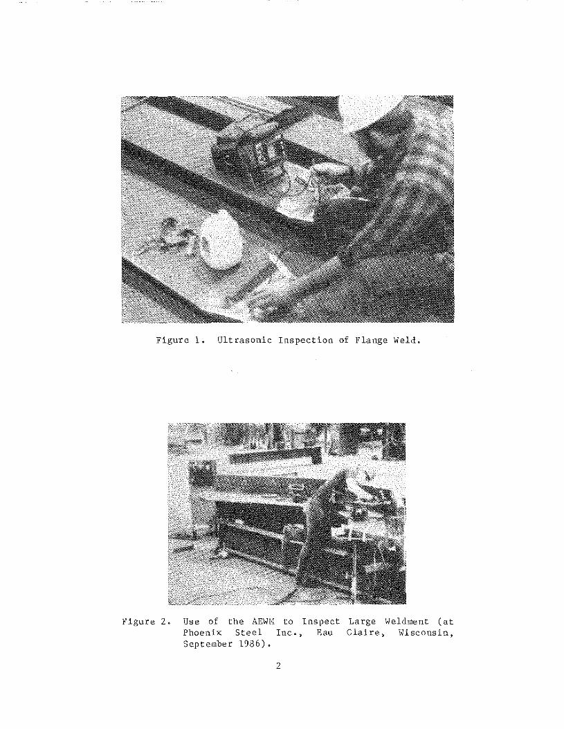
Figure 1. Ultrasonic Inspection of Flange Weld.
Figure 2. Use of the AEWl'l to Phoenix Steel Inc., September 1986).
2
Inspect Large Weldment (at Eau Claire, Wisconsin,

OPERATION OF THE AEWM
The functional operation of the AEWM has been discussed in other reports
and will be explained only briefly herein (1, 2). The AEWM performs weld flaw
detection in real time. It employs pattern recognition to discriminate
between normal background AE noises created by welding processes and AE events
due to the formation of flaws such as slag inclusions or cracks. The AEWM
pattern-recognition process subjects each AE event to a series of sequential
tests. The flaw detection model requires a three-step testing process as
shown on the flow chart in Figure 3. After computing an AE ringdown count
(RDC) for each separate AE event, the first test is applied. If the ringdown
count lies within preset limits (usually 100 to 1,000 counts), an event is
passed to the second test for AE event rate. This test requires that some
number of AE events, which have passed the RDC test, occur within a preset
time interval (usually 1 to 2 seconds). The final test determines whether all
the events that have passed the previous two tests originated from the same
location or at least within a predetermined location tolerance (usually +1
inch). The AEWM also subjects the AE events to frequency spectra analyses for
flaw characterization. Indications with high-frequency components are
categorized as crack-related. Others with lower-frequency components are
categorized as unclassified flaws.
The combination of rate and location tests provides very high
discrimination against interfering background weld noise. The assumptions
employed in the pattern-recognition process are 1) a growing flaw will produce
higher rates of AE activity than noise sources and 2) a flaw, being a
localized phenomenon, will produce a higher rate of AE activity from a
specific location than noise. This form of AE monitoring differs from
conventional AE methods in that it is event-rate based and employs a multi
parametric filtering process to discriminate between noise sources and weld
flaws in real time.
AEWM testing uses linear flaw location. Two AE sensors (transducers)
are normally required to perform those tests. In this research, standard
piezoelectric transducers were employed having peak resonant frequencies in
the range between 150 to 200 kHz. The transducers were wired to GARD 0 dB
gain preamplifiers, which were connected by coaxial cables to analog modules
mounted in the AEWM.
3

The transducers are attached to a weldment 6 inches offset from a weld
line and 2 inches from the plate edges (Figure 4). As the welding
operation progresses, the two transducers monitor acoustic emissions sending
electrical signals to the AEWM for processing. Once the AEWM determines that
a weld flaw has been created, a flaw indicating lamp on the face of the
instrument panel of the AEWM will extinguish, thereby alerting the AEWM
operator that a flaw has occurred at a point along the weld line.
The AEWM is capable of "stand-alone" operation. In that mode, the unit
is calibrated and operated entirely in a self-contained manner. The AEWM flaw
indicating lamp informs the operator that a defect has occurred. Then, the
operator can approximately locate the' flaw in a position between the two
transducers to within 1/16 of the transducer spacing from location indications
provided by a 16-bit light-emitting diode (LED) panel. Also, the flaw category
determined by the AEWM frequency spectra analyses will be displayed on the LED
panel. In the present AEWM, the test data are retained for up to 256 weld
tests (as long as the AEWM is powered). That data can be recalled and
disph.yed on the LED panel. Otherwise, it must be output to a printer or a
disk recorder. A video terminal may be used to support the "stand-alone"
operation to provide better location of any defects occurring between the
transducers (down to a l-inch resolution).
The system also may be operated in a "data-recording" mode, which allows
the AE parameters to be stored on a floppy disk and later retrieved or
reprocessed for hardcopy backup or for post-test analysis of AE data using
various flaw models. It is time consuming to calibrate the AEWM in that mode
of operation, and difficult to maintain the disk drive in long-term
fabrication-shop use.
4

AE FROM PRE AMP
~ ),~;t
FILTERING - STEPI
- FILTERING STEP 2
-FILTERING STEP 3
Figure 3. AEWM Processing Flow Chart for Flaw Detection.
/
WELD 6" TYPICAL LINE OFFSET
SUBMERGERED- ARC WELDING HEAD ACTIVE
TRANSDUCER
TRANSDUCER .,: ARRAY SPACING
2" TYPICAL OFFSET
Figure 4. Schematic of Typical Butt-\leld Showing Normal Transducer Placement.
5


PRELIMINARY STUDY EFFORTS
TEST OBJECTIVES
In September 1986, KTRP received FHWA Contract DTFH6l-86-R-00118 to
perform a long-term shop evaluation of the AEWM. The stated objectives of the
program were l) to perform monitoring operations of fabrication-shop welds
(establish a test data base), 2) to correlate AEWM test results with those
obtained using conventional code-based NDT methods, 3) to evaluate the
performance of AEWM and recommend any follow-up actions or reconfigurations of
the unit, and 4) to prepare recommendations for code modifications to support
the deployment of the AEWM in fabrication shops to inspect steel weldments for
highway bridges.
Those formal objectives were necessary to establish the performance
characteristics of the unit and to determine whether further action was
warranted. Additionally, KTRP had several informal objectives necessary to
extend the utility of the unit for use by fabrication-shop personnel: l) to
determine whether the AEWM could be used by unskilled operators; 2) to
determine whether the AEWM would significantly affect the rate of shop
welding; 3) to determine if any additional benefits such as cost savings,
improved welding operators, better end-products, easing of welding
specifications, or weld-qualification testing were possible; and 4) to obtain
a sufficiently large test record to persuade states and code committees that
the system might warrant consideration for adoption in various welding codes,
regulations, and specifications.
FABRICATION SHOP SELECTION
The first task of this study was to locate a fabrication shop that would
allow the use of the AEWM to inspect welding operations. The plant selected
was High Steel Structures Inc. of Lancaster, Pennsylvania. There were several
reasons for that choice. The shop was located within a reasonable distance of
both the KTRP laboratory and the FHWA offices in the Washington, D.C. area.
High Steel was very active in welded steel-bridge fabrication for a large
number of states, providing high visibility of the AEWM to state personnel at
the plant. Also, it offered the opportunity to inspect a large number of
welds. High Steel had been host for a previous AEWM demonstration, and the
shop personnel were familiar with the unit and its interaction with their
operations.
7

In November 1986, FHWA, High Steel, and KTRP personnel met to establish
guidelines for employing the AEWM at the High Steel fabrication shop. At that
time, it was determined test results should be maintained separate from
conventional NDT information normally furnished to states. This was due to
the experimental nature of the AEWM and the need to prevent any hardship for
High Steel should questions arise about AEWM test results. The decision was
made to acquire conventional NDT results separately from those of the AEWM (in
a double-blind manner) and compare them using an independent third party, the
High Steel QC personnel.
AEWH test results had to be correlated with each weld member and
transmitted independently in an identifiable form to the shop QC personnel for
test comparisons. Also, it was determined that only web and flange butt welds
would be monitored since no significant background laboratory or controlled
experiments had been performed using the AEWM to monitor flange-to-web
connections (with the exception of the large full-penetration weldments
previously monitored by KTRP investigators for the Wisconsin Department of
Transportation). The test duration was set at 6 months. During that time,
KTRP personnel anticipated they would be able to monitor 100 to 125 welds.
AEWM WELD TESTING PROCEDURE
After the meeting with FHWA and High Steel personnel, the decision was
made to emphasize the testing of web butt welds. Web monitoring would produce
more weld length inspected per test than flange monitoring. Therefore,
monitoring of flange butt welds was considered of secondary importance. Also,
it was determined that 100 percent AEWM monitoring of each weld would be
desirable since conventional NDT results would be based on an entire weld and
it would be difficult to correlate test results if only a portion of a weld
was monitored. Transmission of data from KTRP personnel to shop QC personnel
and then to the KTRP principal investigator required preparation of an AEWM
report form {Appendix). The form contained an individual number for each AEWM
test and a space for each shop weld-identification number allowing High Steel
QC personnel to correlate the AEWM tests with conventional NDT results. Also,
the test date and shift number during which the monitoring was performed was
to be noted. The form contained spaces for summary information on the amount
of material tested and also on whether a defect was encountered by either the
AEWM and/or conventional nondestructive testing. A small diagram was included
8

to note the welding direction on each side of the weldment.
A procedure was formulated whereby the Number 1 transducer of the array
was always placed at the starting point of the welding operation. However, it
was necessary to determine where the weld was started in relation to the
initial weld side (or "A face") of the plate. In some cases, it was possible
for the welder to begin welding on the backside (or "B face") from either end
of the weld in relation to the starting point of the pass on the "A face" of
the plate. This was noted by circling the arrow shown on the schematic and
indicating it was the welding direction for the "A face" and then noting the
starting point of the back side ("B face") weld in relation to the "A face"
weld. This allowed determination of defect location if one was encountered on
either side of the plate in relation to the transducer placement.
The FHWA required additional information, including type of steel welded,
plate thickness, weld preparation, plate width, wire type, flux, welding
amperage, voltage, and speed, and preheat. The important AEWM test variables
included the system gain for each channel and the sensor spacing, which was
usually 4 inches less than the total plate width. Spaces were provided on the
form to record that information as well as AE test results for seven passes on
each side of a weld. Also, spaces were included for any comments by the KTRP
technician and for comments by shop QC personnel.
PROJECT STAFFING
The principal investigator prepared the test program. Also, he visited
the fabrication shop at three-week intervals to inspect monitoring operations
and review test results. This allowed close control of shop monitoring and
provided him an opportunity to experiment with various test methods.
The KTRP technician who performed the shop tests had no previous
experience with nondestructive testing or acoustic emission. Due to the
relative ease of operating the AEWM and the noninvolvement of the operator in
defect detection and interpretation, his inexperience was not considered a
detriment. Prior to the shop tests, he received two weeks of training on the
unit. The training consisted of "hands-on'" experience with the AEWM and
instruction on the AEWM operational manual. The technician did not have
experience with the use of the AEWM on welding operations until the shop
testing commenced.
9

The KTRP technician was assigned to conduct routine testing of the shop
welds using AEWM. His daily duties were 1) to contact the shop foreman and
locate a site of ongoing butt-welding operations, 2) to set up the AEWM and
monitor welding activity at that location, 3) to record test results on AEWM
report forms, 4) to pass those forms to shop QC personnel for correlation with
conventional NDT results, 5) to log all test work on a weekly basis, and 6) to
keep back-up copies of the report forms. Additionally, the technician was to
forward the completed (correlated) report forms to the KTRP principal
investigator and contact him should any problems arise with the test program
or equipment.
TEST EQUIPMENT
The shop tests were performed using the AEWM in the "stand-alone" mode.
This was prompted by several facts. The technician did not have sufficient
initial experience or training to operate the equipment in the "data
recording" mode. Also, it required considerable time to calibrate the unit in
that mode of operation. Additionally, the "data-recording" mode required the
use of a Pertec floppy disk recorder, which was the sole data-recording method
supported by the AEWM. Unfortunately, the recorder company no longer existed.
So, it was unwise to operate the disk drive for long periods in a fabrication
shop and risk getting it damaged. The test results had to be transferred to
the shop QC personnel in hardcopy form. It was more efficient for the
technician to immediately record results of each weld pass monitored onto the
AEWM report form than to retrieve them from floppy-disc records.
The AEWM was operated at an intermediate gain level (sensitivity) between
50 to 70 decibels in an attempt to minimize "overcalls" (flaw activity that
was not confirmed by visual inspection or other nondestructive testing).
Previous experience at the Phoenix Steel fabrication shop in Eau Claire,
Wisconsin, prior to this study, indicated this was the best approach to AE
weld monitoring.
The equipment included the Acoustic Emission Technology (AET) 1751
transducers, which had been employed in previous research. Several special
AET 175 transducers were acquired with an integral lead wir-e from the
transducer consisting of RG 58 coaxial cable 6-feet long. Those units were
more damage-resistant than normal AET 175 transducers and, therefore, better
suited for harsh shop use. Temperatures measured on flange welds exceeded 500
°F (especially when preheating was used). As the temperature rating for the
10

AET 175L transducers was limited to around 300 °F, transducers capable of
sustaining higher temperatures were needed to test flange welds. Several
Physical Acoustic Corporation (PAC) RH15 high-temperature transducers were
acquired that were functional to 600 °F. Those transducers had manufacturer
specified resonant frequencies of about 500 kHz.
To avoid problems with signal cables connecting the AEWM to the
transducer preamplifiers, cable lengths were limited to 50 feet. This
provided several benefits. By keeping the cable length to a minimum, problems
with electrical (RF) noise and cable coupling were minimized. Also, short
cable runs kept the technician close to the weld allowing him to observe
welding operations. A portable cart was used to move the AEWM about the shop
and provide close access to the welds. On a few occasions, longer cable runs
(100-feet long) were required. Those were made by coupling two 50-foot cables
together.
To prevent incorrect addressing of the AE signals, a color-coding system
was employed whereby the cables, preamps, transducers, and analog channels
were color-coded to denote the Number 1 channel system (yellow) and the Number
2 channel system (red). Also, the 16-bit LED panel on the face of the AEWM
was color-coded yellow on the left side and red on the right side to provide
consistent addressing of a potential flaw source in reference to transducer
placement. A third analog channel on the AEWM could be used for a "lock-out"
to prevent out-of-array AE noise from entering the linear array. To simplify
testing operations, that feature was not used.
11


FABRICATION SHOP MONITORING
TEST ROUTINE
Monitoring operations at High Steel were initiated on January 6, 1987. A
daily test routine was established whereby the KTRP technician would move the
AEWM from its storage location to a test site on the shop floor and prepare to
monitor welds. Prior to a welding operation, the technician would inspect
the steel plates and record the weldment number printed on one plate. Also,
he would check the welding machine to determine its voltage and welding-wire
feed-rate settings.
Transducer placement and AEWM calibration required about 5 to 10 minutes.
This did not substantially interfere with welding operations. The transducers
were mounted in hold-down assemblies that also incorporated preamplifiers
(Figure 5). Since those assemblies were housed in a single pre-connected
unit, they could be quickly attached to the weldment saving much time compared
to handling separate components. The technician applied a silicone couplant
on the wear faces of the two transducers and then attached them on one side of
the weldment adjacent to the weld line (Figure 6). After the technician had
determined the plate width and established the transducer spacing, he
calibrated the AEWM and prepared for monitoring (Figure 7).
Transducer calibration and coupling was simply verified by using a
screwdriver to tap the steel plate adjacent to the transducer. The technician
viewed the three AE activity indicating lights on the face of the AEWM analog
modules (channels) as he tapped the steel plate to ascertain that coupling had
been achieved. Final gain adjustment was made during the early part of the
first (root) weld pass. During that pass, the technician would view the
indicating lights as they flickered intermittently due to the AE activity from
the welding operation. The preset gain was usually sufficient to properly
calibrate the transducers. However, if the indicating lights on either of the
AEWM modules exhibited a low level of AE activity, the gain was increased.
Source-location calibration was not necessary.
When a welding operation commenced, the technician began the monitoring
process. During welding, he watched both the welder and the AEWM flaw
indicating lamp to determine if some event occurred that might produce a flaw
indication.
13

Figure 5. Magnetic Hold-Down Assemblies Housing the Preamplifiers and Transducers (Note the silicone couplant on faces of transducers).
Figure 6. Attaching Transducer to Flange \leld.
14

Figure 7. Calibrating the AEWM Prior to Monitoring Weld.
15

The AEWM also was connected to a video terminal. Variously, either a
Microbee or an ADM 3A terminal was used. The terminal provided a visual
readout of the location, classification, and ringdown counts (energy) of any
flaw indications after each weld pass was completed.
The fabrication shop employed semiautomatic submerged-arc welding for web
and flange butt-welding operations (Figure 8). The welding machine was
equipped with a hand-held welding gun that contained a rolling wheel to
control its travelling speed along a weld (Figure 9). The welding-wire feed
rate was automatically controlled by the welding machine. The operator
adjusted the vertical offset and lateral position of the welding gun in
relation to the weld groove prior to welding. The only manual control required
during welding was the lateral positioning of the weld gun as the welder
guided it along a weld.
Typically, the shop performed double-bevel groove butt welds. Initially,
a single V-groove butt joint was provided between two plates that were fitted
and then tack-welded together. The welding operator deposited the root weld
pass on the "A face." Typically, two to three passes were required to complete
that weld. Prior to turning a weldment, the "A face" weld reinforcement was
manually ground flush with the plate. Thereafter, the weldment was turned and
the opposite weld face was backgouged to sound metal (Figure 10). Then, a
groove was formed on the back side or "B face" with a hand grinder. The
welder completed the weld, usually in one or two passes. The weld
reinforcement on the back side was subsequently ground flush.
Approximately, 50 percent of all weld metal deposited on webs was removed
either by backgouging or grinding.
Normally, flange butt welds required 15-20 passes on the "A face," which
contained a plate-thickness transition bevel. Then, the weldment was turned,
backgouged, ground, welded, and finish-ground on the back side. In most
cases, only one or two passes were required to complete the back-side weld.
On a percentage basis, less weld material was removed by backgouging and
grinding flange welds than was removed from the web welds.
Conventional NDT operations usually were not performed immediately after
weld completion, especially if radiography was used. Radiography required the
weldments to be moved to a separate test area at one end of the shop. That
was necessary to prevent shop personnel from becoming exposed to radiation.
The handling required to move the weldments in and out of the restricted area
was an additional cost to the fabricator. In some instances, ultrasonic
16

Figure 8.
Figure 9.
Welder Performing Weld on \Veb (Note edge of plate),
Semi-Automatic Submerged-Arc AE transducers located near
Semi-Automatic Submerged-Arc Depositing "A" Face Held on Flange.
1 7
Welding Gun Beveled Side of

Figure 10. Carbon-Air Arc llackgouging on Back Side of a Flange Weld.
18

testing was performed shortly after a weld was completed.
Often, completed weldments were moved to an outside storage yard and in
some cases were not inspected up to 30 days after the weld was completed.
That delayed processing of AEWM report forms the technician had submitted to
the shop QC personnel.
PROGRESS OF AEWM TESTING
In January the shop testing progressed slowly due primarily to the KTRP
technician's unfamiliarity with the operations at High Steel. Initially, KTRP
had obtained permission from two state highway agencies, Vermont and New York,
to monitor their welds. However, in mid-January, it became apparent that
access to welding operations of more highway agencies was necessary to perform
a sufficient number of tests. Therefore, highway agencies of two additional
states, Maryland and New Jersey, were contacted and ~permission was granted to
monitor their welding operations.
Several problems restricted the number of tests performed early in the
shop testing program.
High-temperature transducers necessary to monitor flange operations were
not available during the first several months of testing. The shop routinely
welded flanges routinely on the day shift. Web welding operations were
conducted less frequently on any of three 8-hour work shifts. Shop scheduling
made it difficult for the technician to determine when webs were being welded.
On several occasions, the KTRP technician spent two shifts at the shop waiting
on a web welding operation, only to have it completed during the next shift
after he had left the shop.
Typically, it took from several hours to a half day to complete a web
weld. In part, that was due to shop procedures. Also, High Steel did not
pressure its welders to produce the welds at an accelerated pace.
By the end of February, shop monitoring improved and the technician was
able to test 15-20 welds per month. In March, high-temperature transducers
were acquired and applied on flanges. Some of that work was not successful
and consumed some test time in unproductive monitoring operations.
In early June, it was determined that by the end of the scheduled shop
operations, June 30, 1987, less than 100 welds would have been tested.
Therefore, KTRP requested that the shop testing be extended four months
through the end of October. That request was granted and the shop monitoring
operations continued another four months with permission of High Steel.
19
In early Septell)ber, the high-te"'peratl)re transducer proble"' was resolved.
Both flange and web weld$ could be monitored, increasing the test output. By
the end of the shop work, a total of 153 weldments had been tested. On
October 29, the shop tests at High Steel were terll)inat;ed and KTRP personnel
and equipment; returned to Lexington, Kentucky, for final data an11lyses and
report preparation.
WELD PROCEDURE PREQUALIFICATIO~
In July 1987, the Maryland Dep!lrtll)ent of Transportation requested that
the KTRP technician perform AE monitoring on a weld prequalification procedure
being conducted at High Steel. The purpose of that test was to determine
whether delayed (hydrogen-induced) cracking might occur in a particular
weldll)ent and if a waiting period was necessary prior to conducting
conventional nondestructive testing. Special flaw models that GARD had
deve1oped for post-weld monitoring and delayed cracking were obtained by KTRP.
Those ll)odels were temporarily programmed into the AEWM and used during post
weld monitoring of the test piece.
The initial prequalification test was unsuccessful. After the weld was
completed and post-weld AE monitoring initiated, the KTRP technician left the
shop. On returning the nex:t ll)Orning, he found that the AEWM had been
disconnected by shop personnel, thereby losing all data. A second
preql)alj_fication test was performed. The test procedure required post-weld
monitorin~ for a period of 96 hours. No post-weld cracking was detected by
the AEWM, indicating that the weld configuration and test procedures were not
susceptible to post-weld cracking. Therefore, production welds could be
inspected im~ediatelY upon completion. That test resulted in the easing of
inspection restrictions for the fabrication shop and a cost savings by
reducing weldment handling. The test also demonstrated the long-term immunity
of the AEWM to electrical noise in the shop.
20

TEST PROBLEMS
Several initial problems were experienced in the application of the high
temperature PAC RH15 transducers. In March, they were used in several flange
tests. Unfortunately, the PAC transducers did not fit properly in the hold
down receptacles that were originally designed for the larger AET transducers.
Shims were employed to expand the diameter of the transducers and allow them
to fit snugly into the receptacles. Shimming was achieved by wrapping
electrical tape around the transducers and placing several washers into the
receptacles to make up for the lack of height of PAC transducers compared to
the AET units, During flange welding, temperatures on the transducer
receptacles exceeded 400 °F, which could be anticipated since the temperatures
of the weldments sometimes exceeded 500 °F. Unfortunately, the high
temperatures caused the shim tape to melt. That allowed a transducer to twist
inside its receptacle and uncouple from the weldment surface.
During several flange tests, transducers became uncoupled due to the
shimming problem. Typically, the technician would notice the absence of AE
activity on the indicating lights of one channel of the AEWM. Unfortunately,
that problem sometimes remained undetected until well into the progress of a
weld pass, preventing the detection of acoustic emissions (or flaws). In one
test, large slag inclusion was detected in a flange weld after that occurred.
Inspection of the transducers revealed that one had separated from the
weldment surface, invalidating the monitoring process.
During the initial flange tests, GARD personnel questioned whether the
PAC ·transducers were suitable for use with the AEWM due to their high
resonant frequency (500kHz), The required AE signal frequency for operation
of the AEWM is around 200 kHz. The PAC transducers were shipped to the GARD
laboratory in Niles, Illinois, and subjected to a helium- jet (white-noise)
source to determine their resonant frequencies. The transducers were found to
contain resonant frequency peaks within the operating range of the AEWM and
therefore, were satisfactory for use. Concurrently, properly fitting
transducer receptacles were fabricated. The transducers and new receptacles
were delivered to the KTRP technician in September 1987 and were used
successfully thereafter (Figure 11).
Another problem was false AEWM indications that were termed "center
hits." Early in the test program, AE indications were detected at locations
centered on the transducer array. Typically, those "center hits" would occur
when a welding operation was not in the center portion of a weld.
21
At first, those false indications were attributed to broken tack welds.
However, inspection of data from prior tests showed that many of those
indications were encountered on the "B face" welds. "Center hits" could not
related to that phenomena as the tack welds had been eliminated by backgouging
on the "B face" prior to welding. For some time thereafter, that problem was
attributed to flu>c-crushing noise. Occasionally, "center hits" would be
detected in conjunction with other phenomena such as a welder sliding his seat
along a plate or personnel walking on the weldment being monitored. It was
thought that those actions crushed loose flux particles inducing the false AE
indications. Another suspect source was a welder chipping slag as he
deposited a weld (Figure 12). However, this did not prove to be a cause, as
will be discussed later. These "center-hit" indicatiOJJS occurred almost as
frequently as off-center "valid" or "unconfirmed" AE indications.
It was necessary to identify the cause of "center hits" and seek a
remedy. It was hoped that they could be eliminated by a simple means such as
a modification of the flaw-detection software. The KTRP principal
~nvestigator took the Pertec floppy disk recorder to the fabrication shop in
Septeml;>er 1987. Along with GARD personnel, he instructed the KTRP technician
in the operation of the AEWM in the "data-recording" mode. During that visit,
efforts were made to create false "center hits" by crushing flux, fracturing
fused slag with a chipping hammer, walking on the plate distant from the AE
array, and a number of other fretting types of noise activity. The unit
rejected all of those attempts as noise.
It was concluded the source of the "center hits" was probably "out-of
arr;ty" activity that might be related to electric arcing between underlying
stacked plates and the top plate being welded. Typically, a number of plates
were beveled, fitted-up, tacked welded together, and stacked upon each other
prior to welding. In some cases, the welding-machine ground wire was not
attached directly to the plate being welded, but rather, to an underlying
plate. Movement of a top plate might change its contact with underlying
plates and possibly cause arcing. Arcing would create false "out-of-array"
noise that could be classified as flaws by the AEWM.
AEWM tests were recorded on floppy disks in the "data-recording" mode for
several weeks. Several examples of "center hits" and other "valid" and off
center "unconfirmed" AE activity were recorded for comparisons. If simple
solutions were to be obtained, it was felt that only a few examples of each
type of indications would be needed to differentiate between them. Since the
22

Figure ll. Depositing Weld on Flange (Note magnetic holddown assemblies that contain preamplifiers and transducers).
Figure 12. \-lelder Chipping Flux during Welding Operation.
23
Pertec recorder was the last functioning unit available, its use was
terminated after recording the desired AEWM indications and the unit was
stored until the end of the field tests.
In June, dust problems caused the Microbee terminal to break down.
Thereafter, an ADM 3A terminal was used for the monitoring tests. In August,
it was accidentally knocked off the AEWM cart. The unit was quickly repaired
and returned to the fabrication shop.
In July and early August, the AEWM began to malfunction due to dust. The
unit contained small dust filters on the face of the instrument panel.
However, it was not sealed tightly. Dust was able to enter the AEWM through
the filters and cracks in the instrument cover. Eventually, some push-button
controls and electric circuitry began to operate erratically. That was
remedied by blast cleaning the inside of the weld monitor with compressed air.
Thereafter, the unit functioned properly, but required additional bi-weekly
cleanings. Dust problems eventually affected the operation of the ADM 3A
terminal and caused it to occasionally malfunction. The AEWM and the terminal
were subsequently covered at nights to prevent the entrance of excess dust.
However, normal daily usage allowed considerable dust to enter the units and
occasionally affect their operation.
SUBMERGED-ARC WELDING AND FLAWS
During previous testing at the Phoenix Steel Shop and in the course of
this work, it was observed that submerged-arc welding operations are not
inherently flaw-free, The number of flaws induced by submerged-arc welding did
not appear to be related to the degree of automation nor, in this case, to the
particular welding method employed at High Steel.
During the shop tests, approximately one of five weldments contained a
flaw sometime during the welding operation (often during a root pass). This
contrasted with both the shop QC and QA ND+ results that revealed a low defect
rate for completed butt welds.
ROLE OF THE WELDER IN QUALITY CONTROL
The difference between the initial high flaw rate experienced during
welding and the low final weld-rejection rate is that a welder detects
defects induced in the course of welding and repairs them prior to weld
completion. In making repair decisions, a welder has little interaction with
welding engineers or shop QC personnel. The fact that the final defect
24

rejection rate is very low indicates this procedure is successful where good
workmanship is stressed. In such shops, quality and defect prevention are
emphasized. However, an unfavorable result is an obvious difference in
productivity between welders.
Experienced welders may better judge what welding situations result :i.n
defects. Also, they tend to have higher productivity with fewer problems than
do inexperienced welders. Inexperienced welders spend more time in weld
preparation between passes than experienced welders (Figure 13). Also,
inexperienced welders tend to be more cautious and spend more time inspecting
their work.
In one instance, two experienced welders, who had greatly differing rates
of production, were observed. One welder performed grinding operations at the
end of evety pass. The other performed the same welding operation, but did
not extensively recondition welds between passes. The quality of the output
for both welders was equivalent. But, the less-cautious welder produced
significantly more work than his counterpart.
That variation in productivity occurs because a welder has no readily
available criteria denoting either that a given weld pass is satisfactory or
that it must be repaired. Presently, the only sure indication of weld quality
is provided by nondestructive testing after the welding operation is
completed. If a defect is present, a welder must make a repair. Since weld
defects reflect poorly on a welder in a shop that stresses weld quality, he
becomes overcautious.
Weld cost trends are based on historical performance data. Obviously,
slow welders increase the cost of welding. Although some welders have greater
productivity than overly cautious welders, they produce equivalent quality
welds and therefore, are more cost-effective than their slower counterparts,
Weld costs based on the slow welders result in more expensive bridges to
highway agencies.
Unproductive periods occur during welding operations. Occasionally, a
welder has to abstain from welding while a QC or QA inspector occupies his
work station to perform conventional nondestructive testing on a completed
weld. Another unproductive occurrence is a repair to remove a defect (Figure
14). A welder has to backgouge and grind the defective area prior to
rewelding. Repair welds are usually carefully monitored by bo.th QC and QA
personnel. Oftentimes, preheating operations are required prior to making
repair welds, further slowing the process.
25

Figure 13. Grinding a Surface Blemish Prior to Depositing a Succeeding Weld Pass.
Figure 14. Manual Submerged-Arc Weld Repair of l<eldment.
26
Large

FLAWS ENCOUNTERED DURING TESTING
During the shop tests, no major weld cracks were detected by visual
inspection, conventional nondestructive testing, or AEWM monitoring.
Occasionally, small cracks, termed "crater cracks", would he detected that
were inadvertently created when a weld was stopped due to loss of flux or
welding wire. During work at Phoenix Steel, prior to this study, a crack was
detected by the AEWM. That crack was confirmed by conventional ultrasonic
testing and ensuing repair work.
The most persistent type of flaws are slag inclusions (Figures 15 and
16). Oftentimes, slag inclusions are created during the deposition of a root
pass or by formation of what is termed a "roll." "'Rolls" are caused by the
improper positioning of the welding gun to one side of a groove bevel during
welding. That causes molten weld metal to roll over the flux during the
deposition, possibly trapping some slag (Figure 17). "'Rolls" associated with
slag inclusions were readily detected by the AEWM (Figure 18). Sometimes,
rolls did not create slag inclusions. In those cases, the AEWM did not
indicate flaws. When visually inspected, both cases appear similar.
Typically, welders ground "rolls"' out prior to depositing the next weld pass.
However, several welders just welded over them.
Occasionally, the AEWM detected welding irregularities that might affect
the quality of a completed weld. Typically, those irregularities were related
to simple problems such as loss of flux (Figure 19) or depletion of welding
wire (Figure 20). On several occasions, poor weldment fit-up caused burn
throughs or slag-related problems on the root pass (Figure 21).
In several instances, small porosity was missed by the AEWM. However,
it was subsequently detected by visual inspection. The porosity was apparent
as small dimpled indications on the surface of the completed weld. However,
none of those were severe enough to warrant repairs.
27
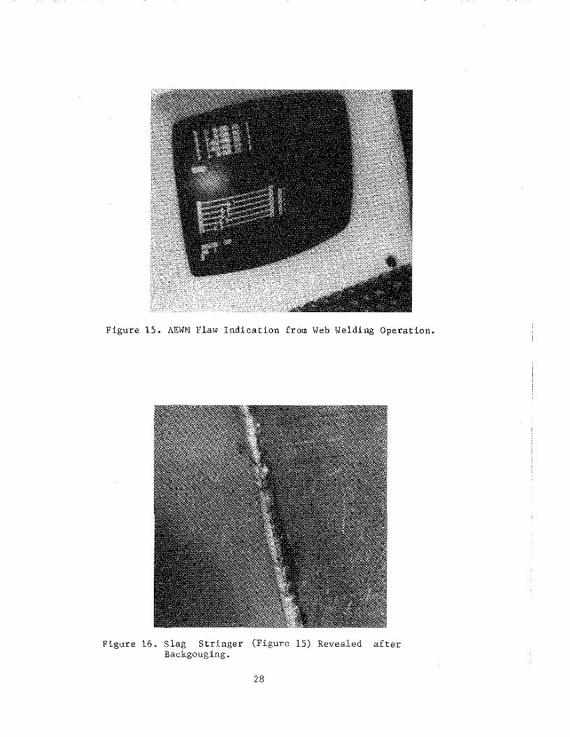
Figure 15. AEWN Flaw Indication from Web Welding Operation.
Figure 16. Slag Stringer (Figure 15) Revealed after Backgouging.
28

Figure 17. Weld "Roll" in Flange Weld (Detected by the AEWM).
Figure 18. Slag Inclusion Backgouging.
in Weld (Figure 17) Revealed by
29

Figure 19. Weld Irregularity Caused by Temporary Loss of Flux.
Figure 20. Flaw at Weld Termination (Slag and Porosity) Detected by AEWM.
30

Figure 21. Trapped Surface Weld Slag Detected by AEW\1 during Root Pass Weld and Subsequently Repaired by Grinding.
31


DATA ANALYSES AND DISCUSSION
AEWM TEST RESULTS
A tabulation of the AEWM test results is provided in Table 1. Data
sunnnaries for the AEWM fabrication-shop testing are shown in Table 2 (webs)
and Table 3 (flanges). A substantial quantity of welding was inspected. A
total of 736.2 feet of completed web and flange welds were monitored with the
AEWM. This corresponds to 4, 935 lineal feet of deposited weld. A total of
1,322 weld passes were monitored during the shop testing program, which ran
from January 6 to October 29, 1987. The average length of web welds monitored
was 70.9 inches and the average length of flange welds monitored was 19.3
inches.
AEWM FLAW DETECTION PERFORMANCE
A total of 263 AEWM indications was encountered during those tests. The
indications were categorized as "valid" flaw indications, "center hits," and
"unconfirmed" (off-center) indications. "Valid" indications were those
detected and located by the AEWM and correlated with flaws visible on the
weld, surface irregularities in the welding process, or indications confirmed
by conventional nondestructive testing (regardless of code-rated severity).
"Center hits" were those AE indications detected within several inches of the
center of the transducer array (weld) that were not verified by other means.
"Unconfirmed" indications were off-center AE activity also not confirmed
visually or by follow-up NDT inspections.
"Valid" flaw indications accounted for approximately 13 percent of the
total AE flaw activity detected by the AEWM in both the web and flange tests.
Twenty-five "valid" flaw indications were detected in web welds and 10 were
detected in flange welds. False "center hits" accounted for approximately
half of all the AE indications detected by the AEWM, including 47.1 percent of
the AE activity for webs and 62.5 percent for flanges. The total number of
"unconfirmed" indications was approximately 39 percent of the total for the
web welds and 23.6 percent for flange welds.
It is important to note that the unit did not experience any undercalls
(missed defects) including visually detected flaws encountered during the
welding operation and repaired, or flaws detected by conventional
nondestructive testing of a completed weldment. Three "valid" AEWM
indications were confirmed by conventional nondestructive testing
33

w
WELD
"'·
2
3
4
5
8
9
10
TEST MTE
1/15
l/19
1!22
1/28
'"'' '"'' '"" 2,U5
2ft)9
'"''
>ElD MATL.
WIRE/ flUX
583 L61/XXX1D
588 L61/XXX1D
588 L61/XXX10
588 L61/XXX10
588 L61 /XXXI 0
588 L61JXXX10
588 L61/XXX10
588 L61/XXX10
588 L61/XXX10
588 L61/XXX:l0
WELD \IJLT
35
33
34
35
32
32
32
32
32
32
>ElD SPD. IIF>II
roo
87
88
100
86
85
78
84
77
77
.,,_ fEAT r"FJ
200
200
MAIL THK.
(IN. I
11/16
l/2
11/16
3/8
1/2
1/2
1/2--3/8
WELD LG.
(IN. I
7I
74
llO
liD
70
70
"' 52
53
"'
WOLD PASSES
6
4
13
!D
5
5
5
4
5
7
TAB..E 1. AEWM FIBRICATION 9-ICP lESf llo'.TA
TOT .LG. INSP.
(IN. I
AEWM GAIN
(dB)
VALID CONY. AE\11 Nor.
INDIC.
NOT TYPE
AEWM CTR. HITS
CTR.HIT Aflret.1 CATEGORY O\£RCPU
0\£RCAI..l CATEGORY DISOJSSIDN AND CCMYENTS
--------------------·-------------426 53-53 D RAD
296 55-59 D D RAD
!43D 5 .. 53 D D RAD
1100 57-59 D D RAD
35D 55-!ll D D ,., 35D 53-55 D D RAD
260 53-03 1 D WID
208 53-55 D D RAD
265 53-$ 1 RAD
364 53-55 3 D RAD
5 c,1{3);c,2;u,3
2 c,1;u,3 D
c,2 D
15 c,2-6;u,1-2 D
6 c,l-4 ;u,l-4 D
3 c,2;u,3;u,6
D D
D 0
D c,6 D
2 u,2;u,3 D
u,2@38n
c,zooo•
1 Vl!iiAL.lY C(Jf. SLAG c,5 @ 50° REPAIRED
OlE lO CHIPPING
DUE TO CHIPPING
1 VI9JALL Y CON=". ROU c,4 @ 34" REA:\IRED
SEE NOTE 1 COFIMD BY RADIIDAPHY
3 VIstW.l. Y CONF. SEE N01E 2
-" II '"'' 588 L61/XXX10 34 84 1/2-3/8 52 4 208 53-55 D D RAD D D
12 2ft}9 588 L61,1XXX:l0 34 84 l/2-J/8 54 5 27D
13 2,U9 588 L61/XXX10 34 84 3/8 52 4 208
!4 2/00 588 L61JXXX10 34 84 1/2 54 4 216
15 2/lD 588 L61/XXX10 32 84 1/2 53 4 212
16 2/10 588 L61JXXX10 32 77 3/8 "' 4 200
17 2/lD 588 L61/XXX:l0 32 84 l/2 53 5 a;5
18 2/lD 583 L6l/XXX10 34 84 1/2 51 4 204
19 2/lD 588 L61JXXX10 34 84 1/2 53 4 212
20 2/11 588 L61JXXXIO 32.4 88 5/8 68 5 340
53-05 D D WID 1
53-55 D D RAD D
53-05 D D WID 2
53-57 D D RAD 2
53-57 3 D RAD
53-57 D ,., 53-57 D D RAD
53-57 D D WID
55-57 D RNJIIJT
,,2 3
D
u,1;c,l
u,l;c,S D
c,2 D
c,4
c,3 D
c,l 2
c;2@32R D
u,1002• u,3@14• u,3@36"
c,1002" u,5@32"
WEl.D OPERATOO. HAD JOG IN PASS c,2@28M
3 VISUAL CONF. SEE NOTE 3 WEllED 0\£R
2 VISI.L3.L CONF. SEE NOTE 4 REPAIRED
2 HITS AT SM LOCATION CFF CENTER
V ISUI\ll Y CDIIF. SI.N.l (ROll ) c,2~0" REPAIRED
------- --------------------------1 AEWM HAD ONE CENTER HIT c,6@24": HIGH STEEL. FOONG SLAG IN FIRST 16• 2 PORSITY u,6@34n, RillS u,3@24", u,1!?40~ DUE TO FWX FEEOIN:i PRIELEffi: ALL REPAIRED 3 Pit.4iOLE POROSITY u,700", c,3@6", c,3@;'': WELDED OVER 4 CAAlER!FISHEYE c,4@36"; POOR FIT ..UP MfOE WELD Kli.GH, POSSIB..E ROOT AREA ACTIVID c,4@20•: ALL REPAIRED

w
TML£ 1. AEWM FAIRICATION SI{}P 1EST DATA {00/TIN.JBJ) ·-----,-----------------------------------WEUJ NO.
21
22
23
24
25
26
27
28
29
lEST
"'" 3i\)4
3,1)5
3,1)8
3,1)9
3(10
3(10
3(12
3(16
3(17
h£Ul MATL.
WIRE/ FLUX
WELD V<I.T
588 L61/XXX1D '32.. 7
36 L61/860 32.5
36 L61/XXX10 '32..5
588 L61/X:O:l0 32.2
588 L61/XXX10 32.2
588 L61/XXX10 34.6
588 L61/XXX10 34.6
572 L61/860 33.4
572 L61/860 34.!
h£Ul SPD. II"')
92
83
84
83
83
93
93
92
92
PREfEAT l'fl
AAfl
""· liN. I
3/4
5/8
5/8
11/16
11/16
350 2 l/4
2 1/4
3/4
WELD LG.
(IN. I
108
66
"' 90
89
24
24
110
300 3 1/4-1 3/4 24
\£LD TOr J.G. PASSES ItfiP.
(IN. I
6 618
4 284
4 248
8 720
8 712
40 960
37 ffi8
6 660
37 888
AEWM GAIN (dB)
$.07
62..{i2
«.02
55-55
53-03
68-68
78-78
59-09
7l~72
VALID CONY. AOO NOf.
I~IC.
0 0
0 0
0 0
0 0
0 0
0 0
0 0
0 0
0 0
NOT TYPE
PAD&UT
RAD
RAD
RAD
RAD
RAD
.., RAD&JT
PAD&UT
AEl<M
ClR. HITS
CTR.HIT AEWM CATEGORY OVERCALL
OI£RCALL CATEGORY DISaJSSION AND CCI>MNTS __ , _____________ , ______ _
6 c,1{3);u,2; 0 c,3{2)
0 0 0
1 u.2@30"
0 0 4
0 0 2
c,3@30" 0
0 0 0
7 c,l-5;u,1{4) 0
0 0
c,2;u,2@27" c,2-3@22"
u,4@58" u,4@70"
c,4@22•
OHPPINi Q.USfD FALSE HITS
CHIPPING POSSIBLE S<X.RCE
CHIPPING POSSIElE SOURCE
FlAI£E
FIJJ<;E
l.n 3() 3(17 572 L61/860 34.1 92 300 3 1/4-1 3/4 24 31 744 61-61 0 0 RAD&JT 4 u,l(2);u,2-4 0 f"lmG£
31 3(18 572 L6l/860 33.6 84 5/8 ll8 7 "" 59-59 0
32 3/19 572 L61/860 33.6 85 5/8 116 500 59-59 0
33 1(15 588 L61/XXX10 33.0 86 ll/16 71 6 426 53-59 0
34 ,,. 588 L61/XXX10 33.1 84 82 6 492 55-$ 0
35 1ftl9 588 L61/860 33.5 85 3/4 81 6 486 53-53
36 1(13 588 L61/XXX10 34.4 94 106 4 424 53-07 0
37 3/23 588 L6l/XXX10 31.9 84 9/16 77 5 385 57-57 0
38 3/24 572 L61/860 33.7 86 9/16 77 5 385 57~57 0
39 3/26 5&3 L61/XXXlO 31.6 87 l/2 69 4!4 55-$ 0
40 4/07 588 L61/XXX10 34.6 96 200 1 3/4-1 20-18 14 380 57-57 6
1 SLAG INCLUSION CONFIMD BY RADHXlRAPHY {OOT COOE REJECTABLE) c,1@12K;u,1@24n;u,2@24";c,3@18M;c,l@l4";c,4@14"
0 "o&UT 0
0 RAD&JT 0
0 RAD 4
0 '"' 0 RAO
0 RAD
0 R!'D&UT 3
0 RAD&JT 0
0 RAD 0
0 RAD&IT
0
0
c,2-4;u,l..{i
c,3@38•
c,4@B'JH
c,2;u,3-4
u,l@32M
4 u,l@24"&44• c,0€0" u,3@14•
1 u,liM2"
3 c,2@16"
0
0
4
0
u,2@40•
u,2(2) c,l-4
u,3@28"
c,~2
CHIPPING CAUSED u,l & c,O;u,l ON ROOT PASS
u ,1 ON ROOT PASS
DUE TO CHIPPIOO.
1 VI.2JALLY aJtF. SlAG c,7@48• REPAIRED
SEE NOli 1

w "'
TABLE 1, AEWM FAIRICATION SI£JP TEST DATA (CCJHHIJED)
·----------------------------------------------------------------------------------·--------------WElD NO.
TEST DATE
l£LD MATt...
WI~/
FWX
wan V<X.T
WELD PRE-
SPD. tEAT (Ifti) (0F}
MATL T>K. (IN,)
wan LG.
(IN.)
WELD TOT .LG. PASSES INSP.
(IN.)
AEliM GAIN (dB}
VALID CONY, NOT
AEWM NOT. TYPE 1/IJIC,
AEWM CTR. HITS
CTR.HIT AEWM OVERCALL CATEGORY OVERCALL CATEGORY DISCUSSION AND C[J+!EiffS
------------------------------------------------------· 41 3/30 588 L61/XXX10 34,7 " 112 64 6
42 3/31 588 L6l/XXXIO 31.9 88 112 69 5
43 4/02 572 L61/86G 32.1 84 200 1!il lb
44 4/06 588 L61/XXX10 34.6 96 200 1-7/B lB-16 13
45 4/06 5B8 L61/XXX10 34,6 96 200 1·7/B 18-16 13
46 4/06 588 l61/XXX10 34,6 96 200 1•7/B 18-16 11
47 4/06 588 L61/XXX10 34,6 96 200 1-3/4 1~16 11 .. 4/06 588 L61/XXX10 34.6 96 200 1 3/4-1 20-18 31
49 4/06 588 L61/XXX10 34,6 96 200 1 3/4-1 2D-18 19
50 4/07 598 L6l/X:O:l0 34.6 96 200 1 J/4-1 18-14 10
51 4/07 588 L61/XXXIO 34.6 96 200 1 3/4-1 2D-18 19
52 4/07 588 L61/XXX10 34,6 96 200 1 314-1 20-IB 14
54 4/13 588 L61/860 32.6 84 5/8 84 9
55 4/14 588 L61/860 32.6 84 5/8 84 8
56 4/14 588 L611860 32.2 84 5/8 84 7
57 4/22 588 L61/XXX10 32.6 86 5/8 56
58 4123 588 l61/XXX10 32,6 84 5/8 65 7
59 4/24 588 L61/XXX10 32,8 86 518 56 8
6D 4/29 588 L61/XXX10 32.6 86 518 66
61 4/30 588 L61/XXX10 32,6 86 518 66
62 4/30 588 L61/XXX10 32,4 88 518 67
63 5/07 572 L61/860 35.0 95 11/16 65
384 55-55 RAO
345 57-57 R/<1
1950 57-'Sl 0 RPll&UT
234 51-59 0 RAD&UT
270 57-59 RAD&UT
198 48-53 0 RADWT
198 48-53 RAD&UT
620 53-53 D RAO&JT
300 53-<9 2 0 AAO&UT
180 52-57 0 D RAO&JT
380 57-57 RAD&UT
'" 57-57 RPJJ&Uf
756 53-57 RAO
672 53•55 PAD
50! 5l-57 0 RAO
462 55-55 0 0 RAD&UT
<55 55-<7 0 AAO&UT
528 55-57 RAD&UT
462 55-59 RAD&UT
396 53-55 D RAO&UT
469 55-57 0 D RAO&ur
325 53-53 0 RAD&UT
c,3@3o•
0
9 c,2-4;u,2(4)
3 c,I-3;u,l
u,Joo• 0
0
u,too• 3
c,2@10" 0
c,2@8" 0
0
c,l@3D"
0
0
u,l@3D"
0 0
0
u,2@28" 0
c,5@18"
c,4@16"
c,l@4" u,l@6"
c,Z;c,3; 2c,4;
c,6;u,5
1 VISUI!.LLY COf\Fffi/1£0 TRAPPED ~AG AT Etll OF R.D. TAB c,l@l6•
&\IN WAS VARIED DURING TEST
FLN<GE
VIS~U.Y CllifiRMED SLAG IN R, TAB c,l@l6• & BlRN lliRU AT u ,4@10.
1 VISI.II\.lLY CONF. ROLl u ,1@4"
BUHEO AET 175 TRANSDLCER
1 VISUALLY CIJIF. toW SPOT c,5J• \<ElDEO
JI'DICATIONS BEGAN IN IIDOT PASS
1 VISI.1\LLY CONF. LOW SPOT ROOT PASS u2,@34"

TABLE 1. AE'ott FAIJUCATION SHJP TEST DATA (CIJITitt.!Bl) ·------------·----------------------------· WELD
NO.
TEST
DATE
WELD WITL.
WIRE/
FWX
wao VOLT
WELD PRE·
SPO. HEAT (I~) (~)
MATL THK. (IN.)
wao LG.
(IN.)
WELD TOT .LG. AEWM VALID CONY. NOT
PASSES INSP. GAIN AEWM t£1T. TYPE (IN.) (dB) INDIC.
AEWM CTR. HITS
CTR. HIT AEWM OVERCALL
CATEGORY OVERCALL CA1EGCRY DISCUSSION AND CCI+ENTS
-------------------------------------------------------64
65
66
67
fi!
69
70
71
w 72
" 73
74
75
76
77
78
79
80
81
82
83
84
5/07
5/07
5/ril
5/13
5/14
5/14
5/19
5/19
5/19
5/22
5/22
5/22
6/09
6/09
6/11
6/11
6/12
7/10
7/10
7/13
7/14
572 L61/860
572 L61/860
'" L61/860
572 L61/860
572 L61/860
572 L61/860
572 L61/860
572 L61/860
572 L61/860
572 L61/860
572 L61/86J
572 L61/860
572 L61/860
572 L61/860
572 L61/860
572 L61/860
572 L61/860
588 L61/860
588 L61!860
588 L61/860
588 l6l/860
35.0 95 11/16 64
35.0 95 11/16 65
35.0 95 11/16 65
34.0 72 3/4 72
34.0 85 3/4 73
34.0 85 3/4 73
34.0 86 3/4 72
34.0 85 3/4 73
34.0 85 314 73
32.6 86 5/a 92
34.0 86 5/a 93
32.2 86 5/a 93
34,0 85 5/a 64
34.2 86 5/a 63
34.0 85 5/a 63
34.0 85 5/a 62
34.0 86 5/a 63
34.0 129 200 2 3/8·1 18
34.0 129 zoo 2 3/8•1 18
34.0 128 200 1 5/8•1 18
34.0 128 200 1 5/8-1 18
5 320 53-53 AAD&UT
390 53•53 RADWT
5 325 53-53 0 RAD.WT
432 55-57 0 RAO&UT
438 55-57 0 0 RAOWT
511 55-57 0 RAO&IT
6 432 55-57 RADt.IJT
6 438 57-57 0 RAD&UT
6 438 ffi-57 0 0 Rt\.D&UT
6 552 55-57 RAD&UT
5 465 57•57 0 RAO!IJT
465 65-55 0 RAD&JT
320 57-55 0 RAO
315 59-55 0 RAO
315 57-57 0 0 RAD
372 57-55 0 RAO
378 57-55 0 0 RAD
11 198 61-61 0 RAO&UT
12 216 61·63 0 0 RJID&UT
11 198 5!H51 0 RAO!IJT
14 198 59-61 0 RAO!IJT
0
2
2
0
0
0
2
2
0
2
0
0
c,1@JQ•
u,2@34•
u,3@32~
u,3!134"
u,1@34"
c,2@32"
u,[email protected]"u,2@42
u,l@32" u,l@28~
c,2@30~
c,l@JO"
u,4@28"
u,3@10"
u,200"
0
0
0
2
0
0
0
0
0
0
0
0
0
0
c,1@4" u,2@20"
u,l@6~
CRATER CRAO:. VISJALLY DETECTED c,1 & c,Z IUD", WELDED AND REM.IRED
VISU!\U Y CONF. SLAG It«:LUSIDN 12" LONG. GROUND OUT AND REFr\.IRED
VISUII.UY CONF. SLAG u,1@36"
GROUND OUT
FLRIGE
FLANGE
RAN OUT OF FLUX DURING PASS, NO REPAIR

TABLE 1. AE'otl FAfRICATION StfJP TEST DATA {C{}ITIItJED) ---------------------------------------------------· WElD
NO.
TEST
DATE WElD I'ATL.
WIRE/
FWX WELD
VOLT WELD FRE•
SlD. HEAT (I~) (°F}
M<TL THK. (IN.}
waa LG.
[IN. l
WELD TOT.LG. PAS~S INSP.
(IN.)
AEWM GAIN (dB)
VALID CONY. NOT AEWM NJT. TYPE
INDIC.
AEWM CTR. HITS
CTR,HIT AEWM OVERCALL CATEGORY 0 'v£RCALL CATEGORY
-------------------------------------------------·----------------------------85 7/17 588 L611860 33.1 83 9/16 62
86 )/2!J 588 L61/860 33.0 83 9/16 63
87 7121 588 L61/860 33.0 83 9/16 63
88 7124 588 L61/850 34.0 128 200 l6
89 7127 588 L61/860 34.0 128 200 16
90 7/29 588 L61/XXX·l0 32,0 86 1/2 62
91 7/30 588 L611XXX•1 0 32.0 86 1/2 63
9Z 7/30 538 L61/XXX•10 32.0 86 1/2 62
93 8/03 588 L61/XXX·10 32.0 86.5 1/2 63
w co 94 8/03 588 L61/XXX·l0 32.0 86 1/2 63
95 8/04 588 L61/XXX·l0 32.0 86 1/2 62
96 8/04 588 L51/XXX·l0 32.0 86 1/2 62
97 8/05 588 L61/860 35.0 129 200 2 l/4-1 24
98 8/07 588 L61/860 35.0 !l9 200 2 1/4-1 23
99 8110 588 L61/860 34.0 128 300 2 118-1 22
100 8/10 588 L61/860 34.4 128 3)0 2 l/8-1 20
101 8/11 588 L611860 35.0 128 >JO 2-1 19
102 8/13 588 L61/860 35.0 129 250 2 5/8-1 1/2 20
103 8114 588 L61/860 35.0 129 250 2 5/8-1 1/2 20
104 8/17 588 L61/860 35.0 129 250 2 5/8-1 1/2 20
105 8/17 588 L51/860 35.0 129 250 2 5/8-1 1/2 20
310 5!r57 0
315 53-55 a
5 315 53-55 0 a
11 176 59-61 0
9 154 59-63 0 D
5 310 55-59 0
315 5l-o5 0
5 310 55-57
315 57-57 a
5 315 57-59
6 372 53-55 0
310 55-57 0 0
13 312 63-65 a 0
14 322 59-63 0
13 256 59-61 0 a
13 260 63-65 2 0
13 247 63--67
16 320 61-66 a
16 340 61 .. 3
17 30l 61-59
16 256 61-63 0 0
RAO&UT
RADWT
IOO&UT
RAO
"" RAD
RAD
RAD
RAD
RAD
RAO
RAD
RAD
RAD
RAO
RAD
RAD
RAD
RAD
RAD
RAD
D
D
D
D
D
0
4
0
c,l@30"
c,l@32"
u,3@12•
c,4@a•
u,3@10"
u,4oo•
u,4-u,5; c,l·c,2
c,UB";
3
D
D
D
2
0
0
a
3
2
c,1@20" u,5@16~
c,21!l24"
u,4@10"
c,ll!lfl"
c,l@26"
u,~28•
c,2@14"
c,2@12"
c,l@14" c,5@1Z" u,2@12"
c,l@6" u,3@12"
C,3@12"
DISCUSSION AND C!Mo!ENTS
SLAG IN R.P., u,5@16"; CHIPPED
VIS, CCNF. SLAG u ,2@20" GROUND GUT
VIS. CONF. NOT SLAG c,6@4", BAD REPAIR. CONFIRMED BY RADIOGRAPHY
c,2 & c,400" PINHOLE PORSITY REF¥\.IRED u,3@10" LOSS OF FLUX
u,3@12• OCOJ~ED, RAN IJJT OF WIRE
u.2@10• lRAPPEO SLAG CHIPPED AND GROUND OUT. VISUAllY CONFIRMED

w
"'
TABLE 1. AEW¥1 FAIRICATION SHJP TEST DATA (CDI!TIMJED}
·----------------------------------------------------------------------------------------·--------------------WElD TEST WELD
ND. llii.TE HATL.
WIRE/
FLUX
WB..D WELD PRE·
va...T 910. HEAT (IR1) {°F)
MAll TIJ(. (IN.)
wao WELD TOT.LG. AEWM
LG. PASSES (IN.)
lt6P. (IN.)
GAm (dS)
VALID CONV. 'DT ASIM tilT. TYPE
UVIC.
AEliM erR. HITS
CTR,HIT AEliM OVERCALL CATEGORY OVERCALL CATEGORY DISCUSSION ANO Cll+IENTS
--------------------·---------------------------------106 8/18 588 L61/860 35.0 129 250 2 5/8-1 112 20 16
107 8/21 572 L61/860 32.7 87 3/4 62
108 8/21 572 L6l/86D 32.5 86.5 3/4 62 8
109 8/25 Al6 L61/860 31.0 86 112 74
110 8!26 A36 LSl/860 32.0 93. 112 74
lil 9/02 5B8 L..61/XXX-10 32.0 87.5 112 54
112 9/02 588 L..61/X.XX·10 32.0 87 112 54
113 9/03 588 L..61/XXX•l0 32,0 87 112 54
114 9/08 588 L6l/XXX·l0 32..0 87.5 112 54
115 9/08 588 L61/XXX-10 32.5 88.1 112 54 5
116 9/08 588 L61/XXX-10 32,5 "' 112 54
117 9/10 572 L61/860 31.0 93 250 2 1/2 22 24
118 9/11 572 L61/8fll 31.5 92 250 2 1/2 22 23
119 9/14 A36 L61!860 33.8 92 3/4 IDB 6
120 9/14 Al6 L61/860 33.8 92 3/4 108
121 9/15 A36 L61/860 33.6 91 3/4 1CB
122 9/17 572 L61/860 31.8 84 7/16 63
123 9/17 572 L61/860 31.8 84 7/16 63
124 9/18 572 L..6l/860 31.9 86 7/16 64
125 9/21 572 L611860 31.5 85 7/16 63 5
126 9/21 572 L..6l/850 31.9 83 7/16 63
127 9/22 572 L6I/860 31.8 85 7/16 63
128 9/22 572 l61/860 31.9 83 7/16 63
129 9123 512 L6l/860 31.9 83 7/16 63 4
256 59"'fil AAO
434 55-55 0 RAO
496 57-fil 0 RAil
370 55-55 0 RAO
370 53-55 RAO
270 53-53 0 RAO
270 53-<7 RAD
270 55-55 RAO
324 55-<3 RAO
270 57-59 0 RAO
270 55-57 0 AAO
528 53-53 0 RAO
506 53-55 0 RAO
648 53-55 0 RAO
756 55-53 0 RAO
7S6 57•53 RAO
378 55-57 0 RAO&JT
315 57-55 0 R!(I&UT
320 55-55 0 0 RAO&JT
315 57-<7 PAD&UT
315 55-55 0 RAD&ur
378 55-<7 AAD&UT
315 53-55 RAD&JT
252 57·59 RAO&UT
0
2
0
0
0
0
0
u,3,4@10•; u,6@10"
u,1@28"
u,6@34" C,3@22" u,5@22"
c,3@24"
c,2@52"
c,3@54"
0
0
0
2
0
u,6@14"
u,Z@14"
u,l@26"
c,l@6"
u,2fil40"; c,3@38"
c,l@58"
u,3@16"
c,3@22"
u,2@26"
c,3@34"
IIJE TO CHIPPING
PINHOLE PORSITY POSSIBLE
RAN OUT OF WIRE DURING PASS; ll.JE TO CHIPPING
DUE TO CHIPPING
RAN OUT OF FWX DlRING PA.SS

..,. 0
WElD TEST h£LD
NO. DATE I'ATL.
WIRE/
FWX
WB..D WELD PRE·
VCLT :1'0. HEAT (Iftl) (OF)
MATL THK. (IN.)
TABLE 1. AEioM FABRICATION SKIP TEST DATA (CIJHHtJED)
wao WELD TOT .LG. AEWM
LG.. PASSES INSP. GAIN {IN.) (IN.) {dB)
VAUD CONY. NOT
AEWM toT. TYPE INDIC,
AEWM CTR. HITS
CTR.HIT AEWM OVERCALL
CATEGORY O'I£RCALL CATEGORY DISCUSSION AND C(M!ENTS
------------------------------------------------------130 9/23 572 L61/860 31.9 83 7/16 63 4 252
131 9/25 A36 L61/860 33.8 as 250 1 1/8 18 12 216
13Z 9/28 A36 L61/860 33.8 85 250 1 1/8 18 10 100
133 9/29 A36 L61/860 34.0 90 250 1 1/8 18 11 198
134 9129 A36 L61/860 33.8 85 250 1 1/8 18 10 180
135 10/01 A36 l61/860 32.0 85 1/2 75 375
136 10/02 A36 L611860 31.8 83 7/16 66 4 264
137 10/02 A36 Uil/860 31.9 83 250 1/2-5/8 16 12 192
138 10/02 A36 L61/860 34.6 85 65 4 260
139 10/06 588 L61./860 32.7 87 250 16 13 208
140 10/07 588 L61/860 32.5 85 250 112-5/8 16 12 192
141 10/07 588 l61/860 32.0 85 250 1/2-5/8 16 12 192
142 10/12 588 L61/XXX-10 34.5 94 1/2-5/8 61 4 244
143 10/13 588 L61/XXX•l0 34,0 93 1/2-5/8 61 305
144 10/13 588 Uil/XXX-10 34.5 94 1/2 61 4 244
145 10/14 588 L61/XXX·l0 34,5 94 1/2 61 4 244
146 10/14 588 Uil/XXX-10 34.5 93 1/2 75 :vs
147 10/20 588 L61/XXX·10 34.5 93 1/2 75 375
148 10/20 588 L61/XXX•10 34.5 93 1/2 75 375
149 10/22 588 Uil/XXX-10 34.5 93 1/2 75 4 300
150 10/23 588 L61/XXX·l0 34.5 93 1/2 75 4 300
151 10/26 588 L61/XXX-10 32.7 93 1/2 75 375
152 10/26 588 L61/XXX•l0 32.5 94 1/2 75 5 375
153 10/28 588 L61/XXX·10 35.0 94 1/2 73 438
57-55 RAD&UT
59-59 0 0 AAO
55-55 0 0 RAD
53-53 0 AAO
53-53 0 AAO
53-53 0 AAO
53-53 0 0 RAO
53-55 0 0 RAO
55-57 0 0 RAO
55-57 0 AAO
53-55 0 RAO
53-55 0 0 RAO
53·55 0 AAO
53-55 0 RAO
55-57 AAO
53-55 0 0 RAO
$-57 0 0 RAO
,,.,. 0 0 RAO
5:>-55 0 RAD
53-55 0 0 RAO
53·55 RAO
53-55 RAO
53-55 RAO
53-55 0 0 RAO
0
0
0
0
2
0
0
0
0
0
u,4@zs•
c,2@6"
u,ll£6"
u,2@6"
c,1@6•
u,l@6"
c,4@28" C,1@28"
0
0
0
0
0
3
0
0
0
u,5@3s•
u,l@26"; u,l@6"
c,ffilB"
c,4@12"; u,6@12" c,6@10"
u,1@22"
c,4@42"
DEFECT CONFIRMED 8Y RADIOGRAPHY
NOT NOT REQUIRED
NOT NOT REQUIRED
NOT NOT REQUIRED
NOT NOT REQUIRED
VISIJ!'\LLY CONFIRMED LCW SPOT GROUND OUT Af{l REmiRED
ER!tlR ON Pltl.ECT NIJI!BER - tilT TESlED
EIR!R ON ffiOJECf NI..MBER - NOT TESTED
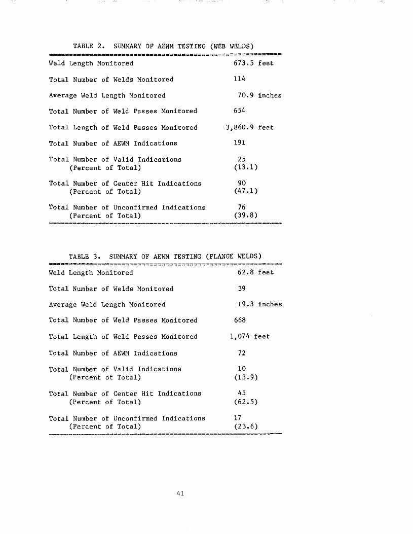
TABLE 2. SUMMARY OF AEWM TESTING (WEB WELDS) ========================================================== Weld Length Monitored 673.5 feet
Total Number of Welds Monitored 114
Average Weld Length Monitored 70.9 inches
Total Number of Weld Passes Monitored 654
Total Length of Weld Passes Monitored 3,860.9 feet
Total Number of AEWM Indications 191
Total Number of Valid Indications 25 (Percent of Total) (13.1)
Total Number of Center Hit Indications 90 (Percent of Total) (47.1)
Total Number of Unconfirmed Indications 76 (Percent of Total) (39.8)
TABLE 3. SUMMARY OF AEWM TESTING (FLANGE WELDS) ========================================================== Weld Length Monitored
Total Number of Welds Monitored
Average Weld Length Monitored
Total Number of Weld Passes Monitored
Total Length of Weld Passes Monitored
Total Number of AEWM Indications
Total Number of Valid Indications (Percent of Total)
Total Number of Center Hit Indications (Percent of Total)
Total Number of Unconfirmed Indications (Percent of Total)
62.8 feet
39
19.3 inches
668
1,074 feet
72
10 (13.9)
45 (62.5)
17 (23.6)
----------------------------------------------------------
41

(radiography). One of those was of defect severity according to the AWS code.
It was a slag inclusion 3-inches long.
Further breakdowns of the AEWM classification of various indications are
shown in Table 4 (webs) and Table 5 (flanges). Comparing "valid" AE activity
of web welds in relation to "center hits" and "unconfirmed" AE activity, about
20 percent of the "valid" indications had low-energy (events with truncated
averages of about 100 ringdown counts) corresponding to an almost equal 23
percent of the "unconfirmed" indications having similar low energies. Both of
those are contrasted to "center hits," which produced approximately 38.8
percent of the indications at similar low RDC levels. "Valid" flange
indications had about 28 percent of the indications with RDC levels greater
than 500 counts compared to 17 percent for "unconfirmed" indications and only
8 percent for "center-hit" indications.
A similar correlation did not exist for flanges. "Valid" flange
indications having low RDC levels comprised 30 percent of the total number
detected (3 of 10) compared to 31 percent for "center hits" (14 of 45), and 41
percent for "unconfirmed" indications (7 of 17). "Valid" AE indications from
flange welds did not produce any activity equal to or greater than 500
ringdown counts compared to 4 percent (2 of 45) for "center-hit" indications
and 6 percent (1 of 17) for "unconfirmed" indications. It should be noted
that flange AE data are somewhat suspect due to the inability of the present
AEWM to accurately locate weld flaws when used with transducer array spacings
less than 20 inches.
The AEWM report forms were reviewed to determine the number of
indications that occurred close to edges of plates that might have been caused
by flaws in runoff tabs or weld start/stop areas. Previously, GARD had
performed shop tests at Allied Steel Company in Chicago, Illinois and had
determined that the only flaws detected were caused by runoff tabs. Web welds
had 5 "unconfirmed" indications within 8 inches of a plate edge. Most web
welds did not employ runoff tabs. Extra plate width was provided, which was
subsequently trimmed from the final webs. That material included the weld
start/ stop areas. The flanges had 13 indications, all "unconfirmed," that
were located within 4 inches of the plates edges. That is significant since
only 17 "unconfirmed" flaws were detected for flanges. If most of those were
caused by flaws in runoff tabs, they would not be detected in any subsequent
inspections, possibly explaining a majority of the flange "unconfirmed"
indications. Since a large number of weld passes were deposited in building
42

TABLE 4. AEWM INDICATION SUMMARY (WEB WELDS)
A. BY INDICATION TYPE =====--============--=====================--========
VALID CENTER HIT UNCONFIRMED AVG RINGOOWN COUNT x 100 UNCLASSIFIED CRACK UNCLASSIFIED CRACK UNCLASSIFIED CRACK
1 3 2 18 17 8 10 2 4 4 9 10 12 8 3 0 3 8 8 6 9 4 0 2 6 6 3 7 5 0 2 1 3 4 2 6 1 3 3 1 2 3 7 1 0 0 0 1 1
TOTAL 9 16 45 45 36 40
B. BY LOCATION IN WELDS ==============---=====--==========--=====
VALID CENTER HIT UNCONFIRMED PASS
NUMBER A FACE B FACE A FACE B FACE A FACE B FACE
1 6 1 13 10 21 7 2 8 3 22 26 29 7 3 5 0 10 2 8 1 4 1 1 6 0 2 0 5 0 0 1 0 0 0
OTHER 0 0 0 0 1 0
TOTAL 20 5 52 38 61 15
43

TABLE 5. AEWM INDICATION SUMMARY (FLANGE WELDS)
A. BY INDICATION TYPE ==================================================
VALID CENTER HIT UNCONFIRMED AVG RINGDOWN COUNT x 100 UNCLASSIFIED CRACK UNCLASSIFIED CRACK UNCLASSIFIED CRACK
1 2 1 7 7 1 6 2 2 1 6 7 1 2 3 1 1 3 3 3 1 4 0 2 7 3 0 1 5 0 0 1 0 0 1 6 0 0 1 0 1 0
TOTAL 5 5 25 20 6 ll
B. BY LOCATION IN WELDS =--===========================--======
VALID CENTER HIT UNCONFIRMED PASS
NUMBER A FACE B FACE A FACE B FACE A FACE B FACE
1 7 1 5 1 3 1 2 0 0 4 3 2 1 3 1 0 7 5 2 0 4 0 0 3 2 1 3 5 0 0 0 3 2 0
OTHER 0 1 11 1 2 0
TOTAL 8 2 30 15 12 5
44

up the thick flanges, it is likely that flaws could be created in the runoff
tabs due to the formation of trapped slag, porosity, or other defects.
For webs, the AEWM frequency spectra analyses, which classified AE
indications as either cracks or unclassified flaws, categorized 16 "valid ..
indications to be cracks and 9 as unclassified flaws. It should be noted that
slag in trapped inclusions may fracture and cause AEWM crack indications.
Forty-five of 90 "center-hit" indications were considered cracks by the AEWM
compared to 45 that were unclassified. Forty '"unconfirmed" indications were
categorized as cracks by the AEWM compared to 36 that were categorized as
unclassified. For flanges, five of the "valid" indications were categorized
as cracks compared to five that were categorized as unclassified. Twenty of
the '"center hit" indications were categorized as cracks compared to 25 that
were categorized as unclassified. Eleven of the "unconfirmed.. indications
were categorized as cracks compared to six that were categorized as
unclassified.
The mean RDC value for "valid" indications in web welds was 267 counts for
unclassified flaws and 344 counts for crack indications. For the "center-hit"
data, unclassified flaws had a mean RDC value of 238 counts compared to a mean
of 236 counts for crack indications. "Unconfirmed" indications had a mean RDC
value of 281 counts for unclassified indications compared to 290 counts for
the crack indications. "Valid" indications for flanges had a mean RDC value
of 180 counts for unclassified indications compared to a mean of 280 counts
for crack indications. That is less than the mean "center-hit'" value, which
was 268 counts for unclassified indications compared to 210 counts for crack
indications. For "unconfirmed" indications, the mean unclassified value was
300 counts and the mean crack value was 200 counts.
Laboratory analyses of the "valid,'" "center-hit, .. and "unconfirmed"
indications recorded on floppy disks was performed by obtaining printouts of
preprocessed AE data from regions where AEWM indications were detected. That
data was manually reviewed in search of any parametric variations that might
differentiate those types of indications. However, review of the data did not
provide any significant variations that could be used to program the AEWM to
discriminate between the three types of indications. It is likely that the
.. center-hit" and "unconfirmed" indications can be eliminated by other means.
45
AEWM PERFORMANCE DURING SHOP TESTING
The large number of AEWM overcalls suggests that the AEWM is inaccurate.
However, the test results are more reflective of the inspection method chosen.
The best method for detecting flaws would have been to stop each test when an
AEWM indication was detected and section the weld to confirm the presence of a
flaw. In a production shop that is not possible. Probably, the "center hits"
would have been eliminated by use of guard transducers. However, that was not
determined until late in the test program.
It is likely that some subsurface flaws were overlooked during visual
inspection ("unconfirmed" indications) and subsequently neglected when
detected by conventional NDT personnel as they were not of defect severity.
That an AEWM indication was "unconfirmed" does not completely impact on its
existence or flaw type (crack, porosity or flag inclusion).
Many "unconfirmed" AE indications probably were caused by small flaws.
The submerged-arc welding process has a high degree of self-purging due to its
high heat input and deep-penetrating weld. It is possible for a small slag
inclusion to be created in one weld pass and then melted out and eliminated by
a successive pass. It is likely that some "unconfirmed" indications were of
that nature. Many "unconfirmed" AEWM indications probably were either too
small to be detected or considered a defect by conventional NDT, were missed
by visual inspection, or were eliminated during the course of subsequent
welding operations or metal removal.
The AEWM frequency spectra analyses did not assist in eliminating the
"center-hit" or "unconfirmed" indications. However, they did assist in
determining if a "valid" indication was detected, especially if multiple flaw
indications were acquired from one weld location. The presence of a crack
classification combined with multiple indications from one location was a good
indicator of slag inclusions. Classification of the exact flaw type was not
provided by the AEWM, at least for flaws encountered in the shop tests.
46
CONCLUSIONS
The AEWM detects flaws as well, if not better, than other forms of
nondestructive testing. That is borne out by the fact that there were no AEWM
' undercalls or missed flaws detected by conventional nondestructive testing.
Several flaws detected by the AEWM also were confirmed by radiography, but
only one of those was considered to be a defect. That indicates the AEWM has
sufficient sensitivity to detect code-rejectable flaws (defects), which is a
fundamental requirement for its future use.
Primary objectives of the long-term shop tests were 1) to establish a
large test data base and 2) to prove that the AEWM was not subject to
undercalls (missed indications) compared to conventional NDT methods.
During most of the test program, the "center-hit" problem was attributed
to flux crushing and it was felt that guard transducers would not resolve that
problem. When that theory was eventually discounted, testing was continued
without guard transducers. That was done to prevent slow test set-ups
(required to affix more transducers) that might reduce the number of welds
tested or interfere with shop operations.
The desire to prevent undercalls resulted in use of a high test
sensitivity due to the AEWM gain settings, which yielded a large number of
"unconfirmed" indications. The AEWM was probably detecting small flaws that
were not easily confirmed by other methods of inspection. Lower gain settings
would have reduced the number of "unconfirmed" overcalls. But, at some point,
the AEWM might have missed a flaw or defect detected by other means (which was
not desired at this point in the AEWM test program).
The shop testing was successful. A large number of welds were monitored
with no undercalls. However, the cause of the overcalls needs to be
determined and they must be eliminated in future tests. The AEWM has proven
capable of detecting code-rejectable defects. Its ability to detect flaws is
somewhat offset by a relative inability to classify flaws both in type and
severity. Its most obvious application would be as a NDT scanning tool to
locate areas on welds for follow-up inspection using conventional NDT methods.
As previously noted, the submerged-arc welding process may be a source of
defects. Also, there is considerable variability in the production rate of
different welders based, in part, on their ability to judge whether a weldment
is sound as it is being fabricated. The most useful feature of the AEWM is
its ability to detect flaws as they are created on a weld-pass basis. The
47
AEWM may be easily adapted to aid welders in evaluating their work in-process.
That would increase the production rate of many welders and may prove to be
its best application from a cost-savings standpoint.
The AEWM may assist fabricators in several important areas: 1) improving
repair decisions, 2) detecting flaws, 3) qualifying weld procedures or
welders, 4) reducing material handling in a shop and welder downtime to
conduct conventional NDT inspections, and 5) reducing or eliminating post-weld
repairs.
The AEWM has exhibited the potential for cost savings and improvements in
weld quality for steel highway bridges. Savings and benefits may not only be
accrued by fabrication shops, but also, by highway agencies employing them.
If the following recommended steps are instituted, it is likely that a
significant impact may be achieved on fabrication shop operations during the
next several years. Those actions should result in considerable savings. The
time and cost required to institute the AEWM would be minimal compared with
efforts previously expended to adopt ultrasonic testing and radiography for
inspection of bridge welds.
48

RECOMMENDATIONS
ELIMINATION OF AEWM FALSE INDICATIONS
Several issues need to be addressed to reduce the number of AEWM
overcalls. Continued work is warranted to eliminate those overcalls and
improve the AEWM to provide a more useful and practical tool.
False AEWM indications could be dealt with in several ways. It is likely
that "center hits" are caused by "out-of-array" AE sources. If guard
transducers are placed on a weldment intervening between the AE noise sources
and the active array, AE noise will not be processed by the AEWM. That would
eliminate ''center hits." The AEWM has the third analog channel dedicated to
this task and contains internal software to support the use of guard
transducers. It would be useful to take the unit back to a fabrication shop
and monitor welding operations using guard transducers. If no "center-hit"
activity is encountered, that would indicate the guard setup has rejected
"out-of-array" AE noise sources. The AEWM has been employed successfully on
in-service bridges using that feature.
The solution to "unconfirmed" overcalls is simply to reduce the system
gain until only defects are detected. That may entail AEWM testing at gains
as low as 40 dB, compared to the 50-60 dB employed in the High Steel tests.
To determine the minimum acceptable system gain, the AEWM should be tested on
a series of welds while progressively lowering the system gain until flaws are
not detected. Then, the gain may be gradually increased until no flaws are
overlooked during a number of tests. The resulting system gain should then be
applied in all relevant test situations. That work could be performed
simultaneously with tests aimed at eliminating "center hits."
AEWM RECONFIGURATION
If the AEWM is to be a practical shop tool, it should be utilized by
welders. It is intended for QC-level inspection and welders make most QC
decisions in terms of determining whether a weld is satisfactory during
fabrication. A welder is usually the sole judge of whether or not an in
process repair is warranted. The AEWM should be reconfigured to serve him.
Incorporating nondestructive testing into shop welding operations may be
considered unusual. Oftentimes, NDT and shop production personnel have
assumed adversary roles. That relationship should be revised. The AEWM should
49

be a welder's tool to assist him in quickly determining whether a weld is flaw
free.
The KTRP technician had very little technical background and no previous
welding or NDT experience prior to this study.
completing his duties and operating the equipment.
He was successful in
That suggests a welder
also could serve as a NDT technician. If a separate technician were required
to operate the AEWM during welding, it probably would not be economically
practical.
The present AEWM requires no more than about 10 minutes to set up and
calibrate once the unit has been moved to a welding area. Disassembly
requires about half that time. A more adaptable unit that was user friendly
to a welder would further reduce the test preparation time.
The unit should be reconfigured. The revised AEWM would be made simpler
to operate. A welder would attach pre-connected transducers to the weldment.
Then, he would press several buttons to sequentially activate and calibrate
the equipment. As welders are often engaged in repetitive work, it would be
possible for shop QC personnel to preset transducer spacing and system gain
settings in the unit. Thereafter, a welder would only need to initiate a
test, stop it, and possibly enter appropriate identification numbers for the
weld being monitored.
It would be feasible to provide automatic calibration and gain controls
whereby the unit would automatically pulse each transducer separately,
determine the calibration distance, and set the system gain to provide the
proper test sensitivity. Start/stop controls could be incorporated into any
welding machine that would automatically start the AEWM when a weld was being
deposited and subsequently stop it when the weld was completed. The AEWM
could be operated with timing devices to indicate the duration of each welding
operation. Data for each weld pass would be recorded and subsequently stored
in battery-backed RAM memory of the reconfigured AEWM. The battery-backed RAM
memory would allow stored test data to be retained when the unit was
unpowered.
The reconfigured unit could incorporate an alphabetic/numeric key pad
that would allow the entry of weld identification numbers and other QC-related
data that would help identify a weldment or provide other useful information.
Also, the unit could be connected to a simple "go-no go" weld parameter
50
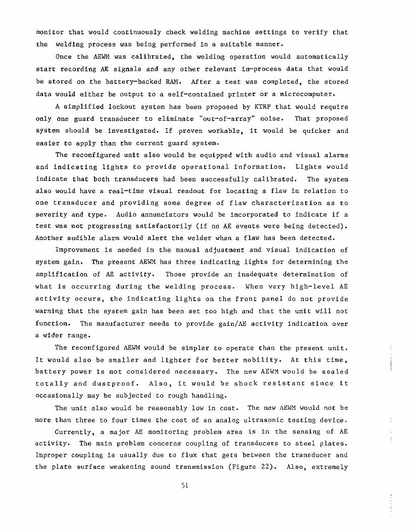
monitor that would continuously check welding machine settings to verify that
the welding process was being performed in a suitable manner.
Once the AEWM was calibrated, the welding operation would automatically
start recording AE signals and any other relevant in-process data that would
be stored on the battery-backed RAM. After a test was completed, the stored
data would either be output to a self-contained printer or a microcomputer.
A simplified lockout system has been proposed by KTRP that would require
only one guard transducer to eliminate '"out-of-array" noise. That proposed
system should be investigated. If proven workable, it would be quicker and
easier to apply than the current guard system.
The reconfigured unit also would be equipped with audio and visual alarms
and indicating lights to provide operational information. Lights would
indicate that both transducers had been successfully calibrated. The system
also would have a real-time visual readout for locating a flaw in relation to
one transducer and providing some degree of flaw characterization as to
severity and type. Audio annunciators would be incorporated to indicate if a
test was not progressing satisfactorily (if no AE events were being detected).
Another audible alarm would alert the welder when a flaw has been detected.
Improvement is needed in the manual adjustment and visual indication of
system gain. The present AEWM has three indicating lights for determining the
amplification of AE activity. Those provide an inadequate determination of
what is occurring during the welding process. When very high-level AE
activity occurs, the indicating lights on the front panel do not provide
warning that the system gain has been set too high and that the unit will not
function. The manufacturer needs to provide gain/AE activity indication over
a wider range.
The reconfigured AEWM would be simpler to operate than the present unit.
It would also be smaller and lighter for better mobility. At this time,
battery power is not considered necessary. The new AEWM would be sealed
totally and dustproof. Also, it would be shock resistant since it
occasionally may be subjected to rough handling.
The unit also would be reasonably low in cost. The new AEWM would not be
more than three to four times the cost of an analog ultrasonic testing device.
Currently, a major AE monitoring problem area is in the sensing of AE
activity. The main problem concerns coupling of transducers to steel plates.
Improper coupling is usually due to flux that gets between the transducer and
the plate surface weakening sound transmission (Figure 22). Also, extremely
51

Figure 22. Transducer Assembly Coupled to \leldment (Note the flux near point of attachment and extruded clear couplant around the base of the transducer).
52

high temperatures may affect the viscosity of a couplant, changing the
transmission quality of AE signals across the transducer/plate interface
during a test (especially when monitoring. flange welds). Another potential
problem occurs when a transducer is bumped or a transducer lead wire is moved,
causing the transducer to slide along a plate. This occurs even when using
heavy magnetic-based hold-down units that attach the transducer to the steel
with high force. That is one reason to have an audible confirmation during
the test to indicate to a welder the unit is detecting AE activity.
Development of mechanically coupled transducers is recommended to
eliminate the coupling problems encountered with the conventional transducers.
That type of transducer has a conical metal wave guide tapered to a fine point
that is glued to the face of a conventional low-temperature transducer. The
wave guide/transducer assembly is attached to a spring-mounted fixture that
forces the tip of the wave guide into the surface of the steel plate. Since
the point of contact is small, a high coupling pressure is achieved providing
sound transmission between the plate and transducer.
Mechanically coupled transducers would eliminate the need for silicone
type couplants, which have proved troublesome. Several attendant benefits
would be gained. The new transducers would provide more consistent coupling
to weldments. That would allow more confidence in the preselection of gain
settings for particular weldments. Mechanically coupled transducers would be
easier and quicker to attach to welds. If a tranducer were disturbed, it
could be designed to slide and yet recouple quickly without significant loss
in coupling efficiency. Those tranducers could be used on both webs and
flanges (that are subject to high preheating temperatures).
FUTURE AEWM TESTING
Prior to AEWM reconfiguration and field testing using welders as AEWM
operators, several preliminary tests should be performed. An initial test
should be conducted to prove that "center hits" can be eliminated by guard
transducers. If "center hits" are eliminated, that would fix the source of
the AE activity as "out-of-array" indications probably caused by arcing or
some related phenomena. During those tests, reduced system sensitivity would
be employed by monitoring at lower gain settings (40 to 45 dB) to eliminate
many "unconfirmed" overcalls.
GARD is presently developing the Acoustic Emission Bridge Monitor (AEBM)
for the FHWA. That unit should be completed and field-tested on bridges by
53

the time this study is completed. That unit employs advanced computer
technology and has many of the features recommended for a reconfigured AEWM.
The new AEBM should be modified to contain software that allows the simplified
lockout of "out-of-array" AE activity. Also, better detection and flaw
characterization capability may be provided by the new unit, which has higher
resolution for flaw location.
Laboratory tests should be performed using the AEBM to develop
mechanically coupled transducers and the simplified guard system. It should be
noted that those new features also would be beneficial in field monitoring of
bridges. Then, laboratory testing would be performed to determine
methodology for making repair and weld conditioning decisions based solely on
AEBM results. That would be accomplished by inducing weld conditions that
might produce flaws. A weld would be deposited and the AEWM would predict
whether a repair should be made. Thereafter, the weld would be sectioned and
the correctness of the AEBM evaluation would be determined.
Upon completion of the laboratory tests, the AEBM should be taken to a
fabrication shop and tested for a 30-day period. After that test, a
specification should be prepared for the reconfigured AEWM. Once that unit
was completed, it would be taken to a fabrication shop, and shop tested for 3
to 6 months. At the fabrication shop, welders would be trained to use the
AEWM and would incorporate it into their welding operations. They would be
requested to increase their reliance on repair decisions based upon AEWM test
results. At the same time, QC personnel would be furnished with hard-copy test
results and would be requested to correlate those results with the final shop
QA testing and any shop QC nondestructive testing. The progress of welders in
adapting to the equipment would be monitored. Welders would be solicited for
suggestions on use of or modifications to the new AEWM.
By the end of the shop tests, a significant quantity of data would be
compiled relative to operation of the reconfigured AEWM. That data would
serve as a basis for convincing state agencies, regulatory groups, and
societies that the reconfigured AEWM should be incorporated in their codes,
regulations, and specifications. At the same time, the reconfigured AEWM
would be turned over to the same fabrication shop and used unassisted for a
period of 6 months. Their work would be documented providing a basis for
further implementation of the AEWM.
54

FUTURE APPLICATION OF Tim AEWM
The greatest benefit of the AEWM will be realized only when its full
utilization is permitted by state and national codes, regulations, and
specifications. AEWM test results should be permitted to replace in-house QC
nondestructive testing normally conducted randomly on a percentage of the
welds applied. It should be emphasized that this is only for QC testing and
not for QA testing. The purpose of QC nondestructive testing is to reduce the
number of defects encountered by QA testing and to maintain the quality of
routine welding operations at an acceptable level. The AEWM is well suited
for that task. After a significant amount of shop experience has been gained
with the unit, it may be possible to limit conventional QA nondestructive
inspections to locations where the AEWM encountered flaw indications. Those
inspections might supplant the random or 100 percent nondestructive testing
that states currently require on some bridge weldments.
The AEWM could be used in lieu of prequalification tests for welders and
weld procedures. Oftentimes, fabricators are confident that their personnel
and weld methods are satisfactory. However, highway agencies require "good
faith" pretests to assure that the shop produces quality weldments. If a shop
were willing to submit to the continuous inspection provided by the AEWM, that
should be sufficient to prove a fabricator's personnel and weld procedures
were satisfactory. The elimination of prequalification tests would result in
considerable savings by both fabricators and highway agencies.
55


APPENDIX
AEWM REPORT FORM

Sheet No -------------
Weldment No ----------
Date --------Shift No _____ _
Plate Steel __ ecA:.::Sc=TecM,___
Plate Thickness _________ in
Weld Preparation ---------
Plate Width _____________ in
AEWM Gain 1 __ 2 __
AEWM Sensor-spacing ______ _
AEWM Test Results ''A11 Side
Weld Pass 1
2
3
4
5
6
7
Comments:
AEWM REPORT FORM
KTRP NDI
High Steel NDI
Weldment Length _____ .in
Total Weld Length Monitored ______ in
"A'' side (Root pass)
Weld Direction
t Weld Wire -----------Weld Flux -----Weld Amperage _______ Voltage ____ _
Welding Speed _____ / in/min
Preheat °F -----
AEWM Test Results 11B" Side
Weld Pass 1
2
3
4
5
6
7
High Steel Test Results=----------------------------------------------------------
58

REFERENCES
1. Prine, D. w., "'Improved Fabrication and Inspection of Welded Connections
in Bridge Structures," GARD Inc., Niles, Illinois, FHWA Report No.
FHWA/RD-83/006, October 1984.
2. Hopwood, T. and Deen, R. c., "Demonstration and Preliminary Evaluation of
the Acoustic Emission Weld Monitor," University of Kentucky Transportation
Research Program, Lexington, Kentucky, Report No. UKTRP-85-23, June 1985.
59


