t hr ci 12020 st underbridges - transport for nsw · t hr ci 12020 st underbridges version 1.0...
TRANSCRIPT

Underbridges
T HR CI 12020 ST
Standard
Version 1.0
Issue date: 21 June 2019
© State of NSW through Transport for NSW 2019

T HR CI 12020 ST Underbridges
Version 1.0 Issue date: 21 June 2019
Important message This document is one of a set of standards developed solely and specifically for use on
Transport Assets (as defined in the Asset Standards Authority Charter). It is not suitable for any
other purpose.
The copyright and any other intellectual property in this document will at all times remain the
property of the State of New South Wales (Transport for NSW).
You must not use or adapt this document or rely upon it in any way unless you are providing
products or services to a NSW Government agency and that agency has expressly authorised
you in writing to do so. If this document forms part of a contract with, or is a condition of
approval by a NSW Government agency, use of the document is subject to the terms of the
contract or approval. To be clear, the content of this document is not licensed under any
Creative Commons Licence.
This document may contain third party material. The inclusion of third party material is for
illustrative purposes only and does not represent an endorsement by NSW Government of any
third party product or service.
If you use this document or rely upon it without authorisation under these terms, the State of
New South Wales (including Transport for NSW) and its personnel does not accept any liability
to you or any other person for any loss, damage, costs and expenses that you or anyone else
may suffer or incur from your use and reliance on the content contained in this document. Users
should exercise their own skill and care in the use of the document.
This document may not be current and is uncontrolled when printed or downloaded. Standards
may be accessed from the Transport for NSW website at www.transport.nsw.gov.au.
For queries regarding this document, please email the ASA at [email protected] or visit www.transport.nsw.gov.au © State of NSW through Transport for NSW 2019

T HR CI 12020 ST Underbridges
Version 1.0 Issue date: 21 June 2019
Standard governance
Owner: Lead Civil Engineer, Asset Standards Authority
Authoriser: Chief Engineer, Asset Standards Authority
Approver: Executive Director, Asset Standards Authority on behalf of the ASA Configuration Control Board
Document history
Version Summary of changes
1.0 First issue.
© State of NSW through Transport for NSW 2019 Page 3 of 99
T HR CI 12020 ST Underbridges
Version 1.0 Issue date: 21 June 2019
Preface The Asset Standards Authority (ASA) is a key strategic branch of Transport for NSW (TfNSW).
As the network design and standards authority for NSW Transport Assets, as specified in the
ASA Charter, the ASA identifies, selects, develops, publishes, maintains and controls a suite of
requirements documents on behalf of TfNSW, the asset owner.
The ASA deploys TfNSW requirements for asset and safety assurance by creating and
managing TfNSW's governance models, documents and processes. To achieve this, the ASA
focuses on four primary tasks:
• publishing and managing TfNSW's process and requirements documents including TfNSW
plans, standards, manuals and guides
• deploying TfNSW's Authorised Engineering Organisation (AEO) framework
• continuously improving TfNSW’s Asset Management Framework
• collaborating with the Transport cluster and industry through open engagement
The AEO framework authorises engineering organisations to supply and provide asset related
products and services to TfNSW. It works to assure the safety, quality and fitness for purpose of
those products and services over the asset's whole-of-life. AEOs are expected to demonstrate
how they have applied the requirements of ASA documents, including TfNSW plans, standards
and guides, when delivering assets and related services for TfNSW.
Compliance with ASA requirements by itself is not sufficient to ensure satisfactory outcomes for
NSW Transport Assets. The ASA expects that professional judgement be used by competent
personnel when using ASA requirements to produce those outcomes.
About this document
This document was developed from the RailCorp standard ESC 310 Underbridges, version 2.2.
This document supersedes ESC 310 Underbridges, version 2.2.
The primary objective of the revision is to align with the requirements of AS 5100:2017 Bridge
design.
This document is a first issue.
© State of NSW through Transport for NSW 2019 Page 4 of 99
T HR CI 12020 ST Underbridges
Version 1.0 Issue date: 21 June 2019
Table of contents 1. Introduction .............................................................................................................................................. 8
2. Purpose .................................................................................................................................................... 8 2.1. Scope ..................................................................................................................................................... 8 2.2. Application ............................................................................................................................................. 9
3. Reference documents ............................................................................................................................. 9
4. Terms and definitions ........................................................................................................................... 12
5. Risk and Safety ...................................................................................................................................... 13 5.1. Risk assessment .................................................................................................................................. 13 5.2. Safety in design ................................................................................................................................... 14 5.3. Safe places .......................................................................................................................................... 14 5.4. Protection screens ............................................................................................................................... 14 5.5. Electrical safety .................................................................................................................................... 14
6. Approved materials ............................................................................................................................... 15 6.1. New and infrequently used materials .................................................................................................. 15 6.2. Formwork ............................................................................................................................................. 15
7. Environment and sustainability ........................................................................................................... 16 7.1. Sustainability assurance requirements ................................................................................................ 16 7.2. Noise .................................................................................................................................................... 16 7.3. Vibration ............................................................................................................................................... 17 7.4. Aesthetics ............................................................................................................................................ 17 7.5. Heritage ............................................................................................................................................... 18
8. Design standards................................................................................................................................... 18 8.1. AS 5100 matters for resolution ............................................................................................................ 18 8.2. TfNSW standard designs ..................................................................................................................... 19 8.3. Bridge technical directions ................................................................................................................... 19 8.4. Importance level .................................................................................................................................. 19
9. Durability ................................................................................................................................................ 19 9.1. Design life ............................................................................................................................................ 19 9.2. Fire ....................................................................................................................................................... 20 9.3. Stray current and electrolysis .............................................................................................................. 20
10. Clearances .............................................................................................................................................. 20 10.1. Underbridges above roadways ........................................................................................................ 20 10.2. Underbridges above railways .......................................................................................................... 21 10.3. Through structure clearances .......................................................................................................... 21 10.4. Navigational clearances ................................................................................................................... 21 10.5. Clearance to electrical infrastructure ............................................................................................... 21
11. Bridge and track configuration ............................................................................................................ 21 11.1. Span arrangement ........................................................................................................................... 22 11.2. Deck joints ....................................................................................................................................... 22
© State of NSW through Transport for NSW 2019 Page 5 of 99

T HR CI 12020 ST Underbridges
Version 1.0 Issue date: 21 June 2019
11.3. Ballasted track underbridges ........................................................................................................... 23 11.4. Direct fixation track underbridges .................................................................................................... 24 11.5. Transom top underbridges ............................................................................................................... 25 11.6. Kerb types ........................................................................................................................................ 26
12. Waterway and flood design .................................................................................................................. 27 12.1. Serviceability limit state flood........................................................................................................... 27 12.2. Ultimate limit state flood ................................................................................................................... 28 12.3. Afflux ................................................................................................................................................ 28 12.4. Requirements of other authorities and agencies ............................................................................. 28 12.5. Scour protection ............................................................................................................................... 29
13. Design loads .......................................................................................................................................... 30 13.1. Rail traffic load ................................................................................................................................. 30 13.2. Braking and traction forces .............................................................................................................. 31 13.3. Track-bridge interaction ................................................................................................................... 31 13.4. Earthquake effects ........................................................................................................................... 33 13.5. Serviceability load combination including wind................................................................................ 33
14. Fatigue .................................................................................................................................................... 33 14.1. Fatigue requirements for bridges on passenger lines ..................................................................... 34 14.2. Design life adjustment ..................................................................................................................... 35 14.3. Particular requirements for steel underbridges................................................................................ 36
15. Deck drainage ........................................................................................................................................ 38 15.1. Decks with joints .............................................................................................................................. 39
16. Deck waterproofing ............................................................................................................................... 39 16.1. Jointed decks ................................................................................................................................... 39 16.2. Jointless decks ................................................................................................................................ 40
17. Ballast mats ............................................................................................................................................ 40
18. Earthworks ............................................................................................................................................. 40
19. Services and utilities ............................................................................................................................. 40
20. Collision protection of underbridges .................................................................................................. 41 20.1. Underbridges over and adjacent to roadways ................................................................................. 41 20.2. Underbridges over and adjacent to rail tracks ................................................................................. 42
21. Derailment containment devices ......................................................................................................... 42 21.1. Approved configurations .................................................................................................................. 43 21.2. Deck spans ...................................................................................................................................... 44 21.3. Through spans ................................................................................................................................. 44 21.4. Bridges with hazard on one side only .............................................................................................. 45 21.5. Protection of ends of through spans ................................................................................................ 45
22. Bridge ends ............................................................................................................................................ 46 22.1. Configuration ................................................................................................................................... 46 22.2. General requirements ...................................................................................................................... 46 22.3. Approach slabs ................................................................................................................................ 47 © State of NSW through Transport for NSW 2019 Page 6 of 99

T HR CI 12020 ST Underbridges
Version 1.0 Issue date: 21 June 2019
22.4. Ballast retention walls ...................................................................................................................... 49
23. Transitions ............................................................................................................................................. 49 23.1. Ballast top bridges ........................................................................................................................... 49 23.2. Direct fixation track and transom top spans .................................................................................... 50 23.3. Intermediate rail support on ballast walls ........................................................................................ 50
24. Earthing and bonding ........................................................................................................................... 51
25. Overhead wiring structures .................................................................................................................. 51
26. Nameplates and plaques ...................................................................................................................... 51
27. Advertising signs................................................................................................................................... 52 27.1. Fatigue design of advertising signs ................................................................................................. 53
28. Documentation....................................................................................................................................... 53 28.1. Investigation reports ........................................................................................................................ 53 28.2. Detailed design reports .................................................................................................................... 53 28.3. Construction drawings ..................................................................................................................... 54 28.4. Technical specifications ................................................................................................................... 54
29. Construction .......................................................................................................................................... 55 29.1. Temporary works ............................................................................................................................. 55
30. Maintenance ........................................................................................................................................... 55
31. Existing bridges ..................................................................................................................................... 56 31.1. Bridge refurbishment ....................................................................................................................... 56 31.2. Bridge upgrade ................................................................................................................................ 56 31.3. Bridge approaches ........................................................................................................................... 58 31.4. Collision protection of existing underbridges ................................................................................... 59
32. Culverts and buried structures ............................................................................................................ 59 32.1. Box culverts ..................................................................................................................................... 60 32.2. Pipe culverts .................................................................................................................................... 60 32.3. Traffic loads ..................................................................................................................................... 60 32.4. Durability .......................................................................................................................................... 61 32.5. Extension and repair of existing culverts ......................................................................................... 61
33. Decommissioning and disposal ........................................................................................................... 61
Appendix A AS 5100:2017 - Matters for resolution ............................................................................. 63
Appendix B BTDs .................................................................................................................................... 70
Appendix C Typical bridge details ........................................................................................................ 72
© State of NSW through Transport for NSW 2019 Page 7 of 99

T HR CI 12020 ST Underbridges
Version 1.0 Issue date: 21 June 2019
1. Introduction An underbridge is a bridge structure that supports a railway track or tracks that can span over
roadways, pathways, flood plains, waterways, other railway tracks and large openings. The
bridge is 'under' the track. Underbridges include viaducts, flyovers, dives, pedestrian subways,
concrete box culvert structures and suspended station structures supporting rail traffic.
The term ‘culvert’ is used to refer to minor structures below track formation that are comprised
of pipes, arches and box shaped openings with integral walls, roof and floor. Box culverts can
comprise precast or cast in place concrete and may include link slabs for multi-cell openings.
2. Purpose This document specifies the design, construction, maintenance, refurbishment, and
decommissioning and disposal requirements for new and existing underbridges on the TfNSW
Metropolitan Heavy Rail Network (formerly known as the RailCorp network).
2.1. Scope This standard covers the requirements for the life cycle of underbridges, from design through to
decommissioning, on the TfNSW Metropolitan Heavy Rail Network. Refer to TS TOC 1 Train
Operating Conditions (TOC) Manual – General Instructions which defines the areas associated
with the network.
This standard provides requirements for the following:
• new underbridges
• refurbishment and upgrade of existing underbridges
• reinforced concrete box culverts (excluding track drainage)
• pipe culverts (excluding track drainage)
This standard does not cover requirements for the following:
• pipe culverts for track drainage; the requirements for these are provided in
T HR CI 12130 ST Track Drainage
• capacity assessment of underbridges; documented in T HR CI 12008 ST Capacity
Assessment of Underbridges
• guardrails; documented in T HR CI 12071 ST Guard rails
• walkways, handrails and refuges; documented in T HR CI 12073 ST Safe Places
© State of NSW through Transport for NSW 2019 Page 8 of 99

T HR CI 12020 ST Underbridges
Version 1.0 Issue date: 21 June 2019
2.2. Application This standard applies to all Authorised Engineering Organisations (AEOs) involved in the design
of new underbridges, and the refurbishment or upgrade of existing underbridges, on the TfNSW
Metropolitan Heavy Rail Network.
Compliance with the requirements in this standard will not, by itself, be sufficient to ensure that
satisfactory outcomes will be produced. Personnel providing services based on the standard
need to bring appropriate expertise to the matters under consideration.
In addition to the requirements of this standard, asset decisions take into account the life cycle
cost considerations specified in T MU AM 01001 ST Life Cycle Costing.
When using the standard, if it is considered that the intent of stated requirements is unclear, a
clarification should be sought from the Asset Standards Authority (ASA).
Where a conflict in requirements exists between this standard and any other referenced
standard, the requirements in standard take precedence.
3. Reference documents The following documents are cited in the text. For dated references, only the cited edition
applies. For undated references, the latest edition of the referenced document applies.
International standards
BS EN 16432-1 Railway applications – Ballastless track systems – Part 1: General
requirements
Australian standards
AS 1742.2 Manual of uniform traffic control devices – Part 2: Traffic control devices for general
use
AS 1743 Road signs – Specifications
AS 5100 Bridge design (all parts)
AS 5100.1:2017 Bridge design – Part 1: Scope and general principles
AS 5100.2:2017 Bridge design – Part 2: Design loads
AS 5100.2 Supplement 1-2007: Bridge design – Design loads - Commentary (Supplement to
AS 5100.2-2004)
AS 5100.3:2017 Bridge design – Part 3: Foundation and soil-supporting structures
AS 5100.8:2017 Bridge design – Part 8: Rehabilitation and strengthening of existing bridges
AS/NZS 1170.0 Structural design actions – Part 0: General principles
© State of NSW through Transport for NSW 2019 Page 9 of 99

T HR CI 12020 ST Underbridges
Version 1.0 Issue date: 21 June 2019
AS/NZS 1554.5:2014 Structural steel welding – Part 5: Welding of steel structures subject to
high levels of fatigue loading
AS/NZS 5100.6:2017 Bridge design – Part 6: Steel and composite construction
Transport for NSW standards
ESC 200 Track Systems
ESC 215 Transit Space
ESC 220 Rail and Rail Joints
ESC 230 Sleepers and Track Support
MN A 00100 Civil and Track - Technical Maintenance (extracted from formerly ESC 100)
SPC 301 Structures Construction
T HR CI 12111 SP Earthworks Materials
T HR CI 12002 ST Durability Requirements for Civil Infrastructure
T HR CI 12008 ST Capacity Assessment of Underbridges
T HR CI 12027 ST Design of Transoms
T HR CI 12071 ST Guard Rails
T HR CI 12073 ST Safe Places
T HR CI 12110 ST Earthworks and Formation
T HR CI 12130 ST Track Drainage
T HR CI 12160 ST Boundary Fences
T HR CI 12190 ST Service Installations within the Rail Corridor
T HR CI 12200 ST Access Roads
T HR EL 08001 ST Safety Screens and Barriers for 1500 V OHW Equipment
T HR TR 00192 ST Ballast
TMC 302 Structures Repair
T MU AM 01001 ST Life Cycle Costing
T MU AM 01003 ST Development of Technical Maintenance Plans
T MU EN 00003 GU AEO Guide to Sustainability in Design
T MU MD 00005 GU Type Approval of Products
T MU MD 00006 ST Engineering Drawings and CAD Requirements
T MU MD 20001 ST System Safety Standard for New or Altered Assets
© State of NSW through Transport for NSW 2019 Page 10 of 99
T HR CI 12020 ST Underbridges
Version 1.0 Issue date: 21 June 2019
T MU MD 20002 ST Risk Criteria for Use by Organisations Providing Engineering Services
TN 016: 2015 Overbridges and footbridges – Earthing and bonding requirements
TS TOC 1 Train Operating Conditions (TOC) Manual – General Instructions
Transport for NSW drawings
CV0048002 Extension for Standard Brick Arch Oviform Culverts
CV0115011 Standard – All Lines – Ballast Retaining Wall – Precast Reinforced Concrete
Details
CV0168626 Guard Rail Special Arrangement –bridges fitted with Alt.1 plates – General
Arrangement
CV0168627 Guard Rail Special Arrangement –bridges fitted with Alt.1 plates – Details of
Concrete Sleepers
CV0191355 Precast concrete girders for underbridges, 10.6 m pretensioned girder – Concrete
details
CV0191356 Standard Concrete Girders for Underbridges 10.6 m pretensioned girder –
Reinforcement details
CV0162590 Standard – All Lines – Intermediate Rail Support at Bridge Ballast Walls
CV0558906 Typical Details – Combined ALT.1 Plates and Guard Rail Plates
Other reference documents
Australian Paint Approval Scheme, Specification 1441 - Permanent Graffiti Barrier
Austroads 2013, Guide to Road Design Part 5B: Drainage: Open Channels, Culverts and
Floodways
Austroads 2018, Guide to Bridge Technology Part 8 Hydraulic Design of Waterway Structures
Centre for Urban Design 2019, Bridge Aesthetics - Design guideline to improve the appearance
of bridges in NSW
DelkorRail drawing RF 0.04.192 CLS Delkor ALT.1 with rail safety rail
Geoscience Australia 2016, Australian Rainfall and Runoff: A Guide to Flood Estimation
International Union of Railways UIC Code 776-2 R Design requirements for rail-bridges based
on interaction phenomena between train, track and bridge
International Union of Railways UIC Code 774-3 R Track/bridge Interaction Recommendations
for calculations
NSW Department of Planning and Environment 2017, Transport Corridor Outdoor Advertising
and Signage Guidelines
© State of NSW through Transport for NSW 2019 Page 11 of 99

T HR CI 12020 ST Underbridges
Version 1.0 Issue date: 21 June 2019
Welding Technology Institute of Australia (WTIA) 2006, Introduction to Fatigue of Welded Steel
Structures and Post-Weld Improvement Techniques TGN-D-02
Work Health and Safety Act 2011
WorkSafe NSW 2004, Safe design of structures code of practice
4. Terms and definitions The following terms and definitions apply in this document:
AEO Authorised Engineering Organisation
APAS Australian Paint Approval Scheme
ARI annual recurrence interval
ASA Asset Standards Authority
BEDC bridge earthquake design category
BTD bridge technical direction
CoG centre of gravity
CP cathode protection
designer a professional engineer as defined in AS 5100.1:2017
DLA dynamic load allowance
LA rail traffic load as defined in AS 5100.2:2017
HDPE high density polyethylene
OHW overhead wiring
OHWS overhead wiring structures
RIM rail infrastructure manager; in relation to rail infrastructure of a railway, means the person
who has effective control and management of the rail infrastructure, whether or not the person–
a. owns the rail infrastructure; or
b. has a statutory or contractual right to use the rail infrastructure or to control, or provide,
access to it
RMS Roads and Maritime Services
SLS serviceability limit state
TfNSW Transport for NSW
ULS ultimate limit state
WB welded beam
© State of NSW through Transport for NSW 2019 Page 12 of 99
T HR CI 12020 ST Underbridges
Version 1.0 Issue date: 21 June 2019
WC welded column
ZLR zero longitudinal restraint
5. Risk and Safety Safe design is mandated in the Work Health and Safety Act 2011 and shall be incorporated into
the design. Guidance on the safe design of structures is available in the WorkSafe NSW's Safe
design of structures code of practice.
The designer shall check for any elements in the bridge provide footholds or ledges that can be
used to gain unauthorised access to climb or to place graffiti.
Security fencing to prevent access to the bridge shall be provided, at locations that have a high
risk of vandalism and graffiti, in accordance with T HR CI 12160 ST Boundary fences.
The design of underbridges shall provide safe access for inspection and maintenance. This
includes access steps, ladders, cages, refuges and walkways.
Appropriate protection shall be installed on bridges to prevent spillages from wagons conveying
mineral products, ballast or spoil from falling through the bridge or off the side of the bridge onto
road vehicles or pedestrians underneath.
5.1. Risk assessment Risk criteria are contained in T MU MD 20002 ST Risk Criteria for Organisations Providing
Engineering Services.
Risk assessment is site-specific and should consider at least the following:
• site condition, including cuttings and embankments
• accident and derailment history at the site
• type of bridge; that is, the potential for collapse and damage to trains
• track clearance to bridge supports
• presence of hazards at the site, for example, track turnouts
• track components in the direction of travel, for example, catchpoints, turnouts, slips,
diamonds or scissor crossovers
• track geometry; that is, straight or curved track
• track speed at the location
• type of rolling stock
• future usage and growth in patronage
• potential for ground settlements © State of NSW through Transport for NSW 2019 Page 13 of 99

T HR CI 12020 ST Underbridges
Version 1.0 Issue date: 21 June 2019
Risk assessment shall also include any other relevant site-specific criteria and shall be used to
determine the extent of mitigation required.
Risk assessments shall be submitted for acceptance by the rail infrastructure manager (RIM).
5.2. Safety in design The design of underbridges, including the refurbishment of existing structures, shall include
safety considerations for construction, operational maintenance and decommissioning workers,
and the potential users of the structures.
The designer shall establish and implement a design process that manages safety across the
full life cycle of the structure. The design process shall comply with T MU MD 20001 ST System
Safety Standard for New or Altered Assets.
The safety in design process in AS 5100 (all parts) Bridge design shall be adopted and risks
and hazards identified and managed.
5.3. Safe places Walkways, refuges and handrails may be used to create safe places for authorised persons to
stand.
Walkways, refuges and handrails shall comply with T HR CI 12073 ST Safe Places.
5.4. Protection screens The requirements for protection screens on underbridges shall be determined as a project
specific requirement and shall be subject to approval by the RIM.
Protections screens shall comply with the requirements in AS 5100.
5.5. Electrical safety Where high voltage aerial lines are located above the bridge, measures shall be taken to ensure
that the transferred potential risk associated with fallen conductors is mitigated.
The deck structure or walkway in the vicinity of overhead wiring (OHW) beneath the bridge shall
be designed to provide an impenetrable barrier intended to prevent persons from contacting
1500 V dc equipment.
Electrical safety screens shall be in accordance with T HR EL 08001 ST Safety Screens and
Barriers for 1500 V OHW Equipment.
© State of NSW through Transport for NSW 2019 Page 14 of 99

T HR CI 12020 ST Underbridges
Version 1.0 Issue date: 21 June 2019
6. Approved materials Approved construction materials for main structural elements are steel and concrete supplied in
accordance with AS 5100.
For bridges with proposed concrete and steel material grades and strengths outside the scope
of AS 5100, the designer shall nominate the appropriate standard for the material and shall be
subject to approval by the Lead Civil Engineer, ASA.
Timber and masonry materials shall not be used as structural elements in the design of new
underbridges. See Section 31 for requirements for existing bridges.
Type approved fibre composite materials may be used for ballast logs and walkway
components.
Proprietary fibre composite transoms are type approved; see Section 11.5 for details and
requirements.
Fibre composite materials may also be used for the strengthening of bridges that are not subject
to fire requirements, in accordance with AS 5100.8:2017 Bridge design – Part 8: Rehabilitation
and strengthening of existing bridges.
Plastic pipes for deck drainage shall be in accordance with RMS Specification R23 Plastic
Flexible Pipes.
6.1. New and infrequently used materials Any products specified in the design documentation that can be reasonably deemed to be new
or infrequently used shall be identified by the AEO and referred to the Lead Civil Engineer, ASA
for approval.
The AEO shall ensure that the manufacturer, constructor and maintainer understand any
particular requirements or practices relating to such products prior to release of the design
documentation. The documentation shall include these requirements.
Durability requirements shall be in accordance with Section 9.
6.2. Formwork Permanent formwork located above 1500 V dc OHW equipment shall comprise a non-corrosive
and non-conductive material in order to eliminate the potential safety risk of deterioration and
subsequent contact with the equipment.
Permanent steel decking formwork shall not be used.
Acceptable products for permanent formwork above electrified tracks include non-conductive
material such as reinforced concrete and fibreglass.
© State of NSW through Transport for NSW 2019 Page 15 of 99
T HR CI 12020 ST Underbridges
Version 1.0 Issue date: 21 June 2019
7. Environment and sustainability The designer of underbridges shall assess and manage environmental impacts for the whole of
the asset life.
The design should also optimise sustainability opportunities over the life cycle of the asset, such
as the following:
• durability of materials to last for the expected design life
• components (including any chemicals for operations and maintenance use) should not
contain any substance of high toxicity if a substance of lower toxicity is available that could
be just as effective
• use of recycled and recyclable materials if they will meet operational requirements
• visual impact and amenity
• resilience to climate change
• ability and ease to maintain and retro fit improvements over time
• disposal and reuse at life cycle end
7.1. Sustainability assurance requirements Design of underbridges shall incorporate solutions to TfNSW key sustainability areas as those
outlined in T MU EN 00008 ST Sustainability Assurance Requirements.
The following documents shall be referred to for sustainability and climate change requirements:
• Clause 10 of AS 5100.1: 2017 Bridge design – Part 1: Scope and general principles
• T MU EN 00003 GU AEO guide to sustainability design
7.1.1. Ambient Environmental Conditions
Underbridges shall be designed to operate under the current and projected environmental
conditions defined in T MU EN 00005 ST Ambient Environmental Conditions.
7.2. Noise The designer shall determine the noise performance requirements for a new bridge or a bridge
upgrade at the planning stage. Requirements under NSW Environment Protection Authority
(EPA) legislation shall be identified.
Agreement on noise performance requirements shall be obtained from the RIM. The noise
requirements shall take rail roughness into account in accordance with the relevant standards.
© State of NSW through Transport for NSW 2019 Page 16 of 99
T HR CI 12020 ST Underbridges
Version 1.0 Issue date: 21 June 2019
Underbridges comprised of ballasted trackform or direct fixed trackform with approved resilient
rail plates, supported on a concrete deck that is designed in accordance with this standard, are
deemed to satisfy this requirement.
Refer to T MU EN 00006 GU AEO Guide to Noise and Vibration for guidance.
7.2.1. Noise barriers The environmental assessment of the project shall determine whether noise barriers are
required on an underbridge.
Noise barriers where required, shall comply with the following:
• designed in accordance with AS 5100 and other requirements in this standard
• fixed to the outside face of ballast kerbs, girders or walkway of an underbridge
• not fixed to the top of the ballast kerbs
• extend to the end of the approach slab (where provided)
• designed to accommodate bridge movement
Where the noise barrier is extended beyond the end of the approach slab, the extended portion
shall comply with T HR CI 12070 ST Miscellaneous Structures.
7.3. Vibration The designer shall determine the vibration performance requirements for each project at the
planning stage. Requirements under EPA legislation shall be identified.
Agreement on vibration performance requirements shall be obtained from the RIM.
Underbridges comprised of ballasted trackform or direct fixed trackform with approved resilient
rail plates, supported on a concrete deck that is designed in accordance with this standard, are
deemed to satisfy this requirement.
7.4. Aesthetics The final appearance and aesthetic qualities of a bridge should be considered in the design
process.
Designs for bridge structures should also be considered in relation to the environmental context.
Sensitive contextual design involves being responsive to a particular setting. Structures should
be designed such that they make a positive visual contribution to their surroundings.
Refer to RMS Bridge Aesthetics - Design guideline to improve the appearance of bridges in
NSW for information on aesthetic treatment of underbridges.
© State of NSW through Transport for NSW 2019 Page 17 of 99
T HR CI 12020 ST Underbridges
Version 1.0 Issue date: 21 June 2019
7.5. Heritage Whilst rail heritage listings typically comprise a station group or precinct, a number of
underbridges are separately listed as individual items.
In station precincts, underbridges may be included in the heritage curtilage, so the maintenance
of these related elements should be considered sympathetically.
Heritage significance should be considered at a sufficiently early stage of a project to be
satisfactorily addressed in concept designs.
Where bridges need to be modified, anticipated maintenance requirements for maintaining and
conserving the heritage fabric shall be taken into account at all design stages.
Alternative approaches to conservation, including appropriate means of protecting significant
fabric from damage and vandalism, may be required for bridges (and remnant sections of
bridges) that are no longer being used.
All approvals required from the Office of Environment and Heritage (OEH) shall be obtained
prior to commencement of detailed design.
8. Design standards All underbridges and associated elements (for example, retaining walls and wing walls) shall be
designed in accordance with AS 5100, other relevant Australian standards and the
requirements specified in this standard.
Where there is a conflict between standards, the requirements of this standard shall take
precedence.
Where the designer proposes to adopt design methods, procedures and requirements which
differ to those in AS 5100, approval from the Lead Civil Engineer, ASA shall be obtained.
The designer should consider the effects of possible future developments on the bridge after it
is constructed.
Unless noted otherwise in this standard, the default values for any constant or variable
nominated in the tables and clauses in AS 5100 shall be adopted. If the AEO considers a
particular default value to be inappropriate, then the requirements shall be discussed with Lead
Civil Engineer, ASA to develop an agreed value.
8.1. AS 5100 matters for resolution Matters that shall be confirmed and accepted by TfNSW before commencing design are
nominated in AS 5100.
Appendix A contains the AS 5100 list of matters for resolution mapped against the TfNSW
requirements in relevant sections within this standard.
© State of NSW through Transport for NSW 2019 Page 18 of 99

T HR CI 12020 ST Underbridges
Version 1.0 Issue date: 21 June 2019
8.2. TfNSW standard designs TfNSW has standard drawings associated with bridge design and construction. Some of these
standard design and drawings are referenced in this standard.
The use of standard designs is not mandatory unless required in this, another TfNSW standard
or by the RIM.
Where the designer proposes to adopt a standard design or detail for a specific bridge location,
the designer shall assess the currency and suitability of the standard design for use and where
necessary, shall specify modified or alternative designs. Modified or alternative designs shall
comply with all relevant TfNSW and Australian standards, as applicable.
8.3. Bridge technical directions The Roads and Maritime Services (RMS) publishes a suite of bridge technical directions
(BTDs). Several of these technical directions are relevant to the design of underbridges and
shall be adopted by the AEO.
Where a conflict exists between the requirements of this standard and an RMS BTD, the
requirements of this standard shall take precedence.
The RMS BTDs relevant to underbridges are listed in Appendix B. The list is current at the date
of publication of this standard.
The designer shall establish the currency of the list and determine whether new technical
directions are relevant to the design of underbridges.
8.4. Importance level The minimum importance level in accordance with AS/NZS 1170.0 Structural design actions
Part 0: General Principles for underbridges (including culverts) shall be level 3.
Where an underbridge is required for post-disaster use, the importance level shall be 4.
9. Durability The durability requirements shall be in accordance with T HR CI 12002 ST Durability
Requirements for Civil Infrastructure.
9.1. Design life The design life of underbridge items are specified in T HR CI 12002 ST. This is typically
120 years for primary structural elements and also for items which cannot be easily maintained
or replaced.
© State of NSW through Transport for NSW 2019 Page 19 of 99

T HR CI 12020 ST Underbridges
Version 1.0 Issue date: 21 June 2019
9.2. Fire Requirements for new underbridges that are designed for fire resistance do not exist; however,
project requirements, as determined from site-specific risk assessment, or as nominated by the
RIM can apply.
For example, bridges over low clearance public access areas may be subject to vandalism and
may require design for fire resistance, or the underbridge may be part of station or building
complex that is required to be designed for fire.
Where a project requires an underbridge is to be designed for fire resistance, the following
requirements shall apply:
• The time dependent curves and performance requirements for fire resistance shall be in
accordance with AS 5100, unless otherwise specified.
• Where bridges are specified to require design for cellulosic fire resistance (AS 1530.4 fire
curve), the minimum performance shall be determined on a project basis; however this
shall be not less than 120/-/- (that is, 120 minutes structural adequacy with nil for insulation
and integrity).
• The applicability of RWS and RABT-ZTV (Rail) curves for hydrocarbon fires shall be
investigated for bridges on freight or mixed lines.
9.3. Stray current and electrolysis The AEO shall incorporate the requirements for stray current and electrolysis prevention in the
underbridge design. Requirements for on-going monitoring shall be included in the durability
plan.
10. Clearances Clearances above, below and within bridge decks shall be as specified in Section 10.1 to
Section 10.5.
10.1. Underbridges above roadways Where an underbridge passes over a road, the vertical clearances beneath the structure shall
comply with the requirements in AS 5100.
The horizontal clearances shall be determined in consultation with the road authority and
provision shall be made for any future requirements.
Where the clearances specified in AS 5100 cannot be satisfied, approval from the road authority
and the RIM shall be obtained and shall be subject to an approval from the Lead Civil Engineer,
ASA.
© State of NSW through Transport for NSW 2019 Page 20 of 99

T HR CI 12020 ST Underbridges
Version 1.0 Issue date: 21 June 2019
10.2. Underbridges above railways Vertical clearances to bridge structural members above rail level shall comply with ESC 215
Transit Spaces, or as specified in this standard.
The minimum horizontal clearance to any existing or proposed track centre line from the face of
any pier, column, and abutment or deflection wall shall be in accordance with ESC 215.
10.3. Through structure clearances The clearances to the nearest face of any element of a through structure shall be not less than
the required clearance specified in ESC 215.
The minimum width of the bridge deck is specified in Section 11.3.1 for ballast top decks and
Section 11.4.1 for direct fixed decks.
10.4. Navigational clearances Clearances over navigable waterways shall be agreed with the relevant waterway authority and
the RIM.
10.5. Clearance to electrical infrastructure Electrical infrastructure within the rail corridor may include aerial lines, 1500 V dc overhead
traction wiring and equipment and exposed low voltage equipment.
Bridges shall be designed and constructed to ensure that minimum clearances are observed to
all electrical power lines and equipment, as defined within Australian standards, the regulations
of the relevant electrical authorities and TfNSW electrical standards.
Clearances to overhead wiring structures (OHWS) constructed on bridges shall comply with
ESC 215.
11. Bridge and track configuration The trackform for a new underbridge or replacement underbridge shall be either ballasted or
direct fixation.
Mechanical rail joints are not permitted on bridges. Anchoring of track and provision for
expansion switches shall be in accordance with ESC 220 Rail and Rail Joints.
Rail fasteners on underbridges shall be in accordance with ESC 230 Sleepers and Track
Support.
© State of NSW through Transport for NSW 2019 Page 21 of 99
T HR CI 12020 ST Underbridges
Version 1.0 Issue date: 21 June 2019
11.1. Span arrangement The arrangement of spans for an underbridge shall comply with the requirements specified in
AS 5100.
11.1.1. Underbridges above roadways Where a new or replacement bridge over a roadway is proposed, the RIM shall liaise with the
road authority to determine the requirements for any future road widening.
11.1.2. Underbridges above railways Where a new or replacement bridge over other tracks is proposed, the RIM shall determine the
requirements for any future tracks and access roads.
The configuration of underbridges over railways shall comprise a clear span between
abutments.
11.2. Deck joints The preferred configuration of bridge superstructure is one that provides a jointless deck within
each span, that is, without gaps or non-structural joints (joints not contributing to load transfer)
in the transverse or longitudinal direction within the span.
The concept development stage of all underbridge projects shall specifically address the issue
of deck jointing. If deck joints within a span are proposed, then a justification of the proposed
deck arrangement shall be included.
11.2.1. Decks without joints (jointless decks) All bridges shall be designed with jointless decks within each span where it is structurally
suitable and the construction is not constrained by the need to accommodate railway
operational requirements.
Examples of compliant jointless bridge decks are as follows:
• decks comprised of precast contiguous planks or spaced beams and girders, with a
composite cast in situ concrete deck slab
• decks comprised of individual concrete beams that are transversely stressed together by
fully grouted high tensile steel bars or tendons to behave in a structurally monolithic
manner, and with fully grouted vertical joints between the beams
Figure 2 to Figure 7 in Appendix C show typical details of jointless decks.
© State of NSW through Transport for NSW 2019 Page 22 of 99
T HR CI 12020 ST Underbridges
Version 1.0 Issue date: 21 June 2019
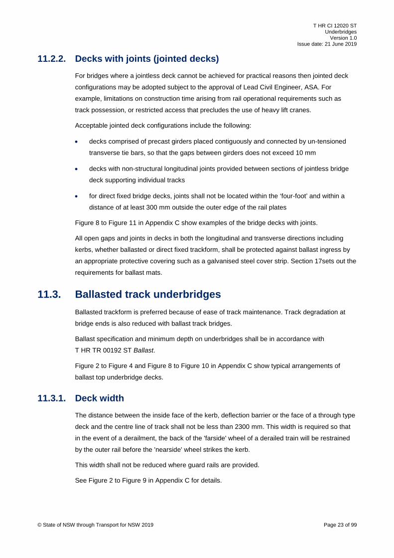
11.2.2. Decks with joints (jointed decks) For bridges where a jointless deck cannot be achieved for practical reasons then jointed deck
configurations may be adopted subject to the approval of Lead Civil Engineer, ASA. For
example, limitations on construction time arising from rail operational requirements such as
track possession, or restricted access that precludes the use of heavy lift cranes.
Acceptable jointed deck configurations include the following:
• decks comprised of precast girders placed contiguously and connected by un-tensioned
transverse tie bars, so that the gaps between girders does not exceed 10 mm
• decks with non-structural longitudinal joints provided between sections of jointless bridge
deck supporting individual tracks
• for direct fixed bridge decks, joints shall not be located within the ‘four-foot’ and within a
distance of at least 300 mm outside the outer edge of the rail plates
Figure 8 to Figure 11 in Appendix C show examples of the bridge decks with joints.
All open gaps and joints in decks in both the longitudinal and transverse directions including
kerbs, whether ballasted or direct fixed trackform, shall be protected against ballast ingress by
an appropriate protective covering such as a galvanised steel cover strip. Section 17sets out the
requirements for ballast mats.
11.3. Ballasted track underbridges Ballasted trackform is preferred because of ease of track maintenance. Track degradation at
bridge ends is also reduced with ballast track bridges.
Ballast specification and minimum depth on underbridges shall be in accordance with
T HR TR 00192 ST Ballast.
Figure 2 to Figure 4 and Figure 8 to Figure 10 in Appendix C show typical arrangements of
ballast top underbridge decks.
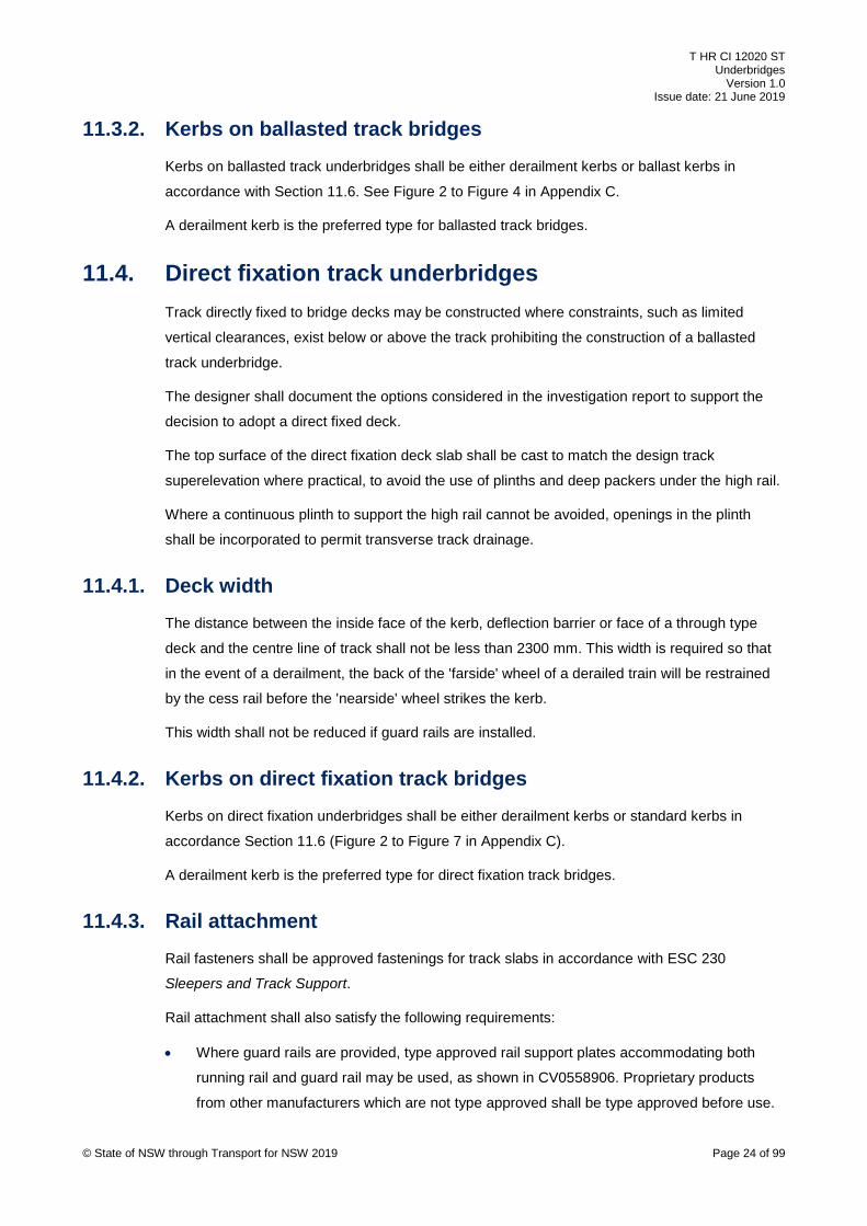
11.3.1. Deck width The distance between the inside face of the kerb, deflection barrier or the face of a through type
deck and the centre line of track shall not be less than 2300 mm. This width is required so that
in the event of a derailment, the back of the 'farside' wheel of a derailed train will be restrained
by the outer rail before the 'nearside' wheel strikes the kerb.
This width shall not be reduced where guard rails are provided.
See Figure 2 to Figure 9 in Appendix C for details.
© State of NSW through Transport for NSW 2019 Page 23 of 99
T HR CI 12020 ST Underbridges
Version 1.0 Issue date: 21 June 2019
11.3.2. Kerbs on ballasted track bridges Kerbs on ballasted track underbridges shall be either derailment kerbs or ballast kerbs in
accordance with Section 11.6. See Figure 2 to Figure 4 in Appendix C.
A derailment kerb is the preferred type for ballasted track bridges.
11.4. Direct fixation track underbridges Track directly fixed to bridge decks may be constructed where constraints, such as limited
vertical clearances, exist below or above the track prohibiting the construction of a ballasted
track underbridge.
The designer shall document the options considered in the investigation report to support the
decision to adopt a direct fixed deck.
The top surface of the direct fixation deck slab shall be cast to match the design track
superelevation where practical, to avoid the use of plinths and deep packers under the high rail.
Where a continuous plinth to support the high rail cannot be avoided, openings in the plinth
shall be incorporated to permit transverse track drainage.
11.4.1. Deck width The distance between the inside face of the kerb, deflection barrier or face of a through type
deck and the centre line of track shall not be less than 2300 mm. This width is required so that
in the event of a derailment, the back of the 'farside' wheel of a derailed train will be restrained
by the cess rail before the 'nearside' wheel strikes the kerb.
This width shall not be reduced if guard rails are installed.
11.4.2. Kerbs on direct fixation track bridges Kerbs on direct fixation underbridges shall be either derailment kerbs or standard kerbs in
accordance Section 11.6 (Figure 2 to Figure 7 in Appendix C).
A derailment kerb is the preferred type for direct fixation track bridges.
11.4.3. Rail attachment Rail fasteners shall be approved fastenings for track slabs in accordance with ESC 230
Sleepers and Track Support.
Rail attachment shall also satisfy the following requirements:
• Where guard rails are provided, type approved rail support plates accommodating both
running rail and guard rail may be used, as shown in CV0558906. Proprietary products
from other manufacturers which are not type approved shall be type approved before use.
© State of NSW through Transport for NSW 2019 Page 24 of 99

T HR CI 12020 ST Underbridges
Version 1.0 Issue date: 21 June 2019
• The minimum clearance from the top of the bridge deck to the underside of the running rail
shall be 60 mm in order to facilitate rail maintenance.
• Where grout is used under the rail plate, the maximum height of the grout bed shall be
60 mm and the minimum height shall be 15 mm.
• For grout thicknesses less than 24 mm, high density polyethylene (HDPE) packers may be
used instead of grout.
• Anchor bolts shall be designed for the actions resulting from the design horizontal loads.
• Only high impact epoxy grouts and mortars (minimum 7-day compressive strength
110 MPa @ 10 °C, minimum 25 MPa @ 5 hours @ 10 °C) developed to withstand the high
dynamic effects from rail traffic and movement of the deck and to the maximum thickness
specified shall be used.
• The grout shall not contain metallic elements.
• Cementitious grouts are not permitted.
• The grout bed shall provide a minimum of 75 mm edge distance to the outside of the rail
plate anchor bolt to avoid cracking of the grout.
• Where epoxy grout pads are poured under suspended rail plates (top down construction),
HDPE pads used under the rail plate shall be at least 8 mm in thickness to prevent heat
distortion and warping. Refer to ESC 230 Sleepers and Track Support.
• Where the hog of a girder or track grading results in gaps under the rail greater than
60 mm, galvanised steel packers (not HDPE) may be used and designed so that the full
lateral restraint to the holding down bolt is provided.
• For large gaps under the rail, concrete plinths are preferred.
11.5. Transom top underbridges Transom top bridges shall not be used for new or replacement bridges. Where there is no
practical alternative to a transom top bridge for a particular bridge site, approval from the Lead
Civil Engineer, ASA shall be obtained before detailed design commences.
The designer shall document the options considered including life cycle costing and prepare a
risk assessment to support the decision to adopt a transom top bridge. The risk assessment
shall be in accordance with Section 5.
Figure 20 in Appendix C shows a typical arrangement of a transom top underbridge.
11.5.1. Transoms Transoms shall comply with T HR CI 12027 ST Design of Transoms.
© State of NSW through Transport for NSW 2019 Page 25 of 99

T HR CI 12020 ST Underbridges
Version 1.0 Issue date: 21 June 2019
11.5.2. Rail plates on transom top underbridges Rail plates on new transom top underbridge shall be in accordance with ESC 230 or type
approved products.
Refer to T HR CI 12071 ST Guard Rails for combined running rail and guard rail requirements.
All type approved products are published on the TfNSW website. Proprietary products from
other manufacturers that are not type approved shall be type approved before use in
accordance with T MU MD 00005 GU Type Approval of Products.
11.6. Kerb types Three types of kerbs may be used on underbridges. The kerb types are as follows:
• ballast kerb – used to retain ballast on ballasted track underbridges
• standard kerb – kerb that does not perform the function of a derailment kerb or ballast kerb
and defines the edge of the deck on a direct fixed track underbridge
• derailment kerb – used to keep derailed bogies tracking parallel to and in close proximity to
the rails in addition to the function of either a ballast kerb or standard kerb
11.6.1. Ballast kerbs Ballast kerbs shall comply with the following:
• the height of kerbs above concrete decks shall be a minimum 600 mm, with a minimum
100 mm allowance above the top of ballast based on the design rail level
• the required height of the kerbs shall be determined by assuming that the ballast profile
extends horizontally from the end of the sleepers to the kerb
Note: the kerb on the high rail side of the bridge will be higher than the kerb on the low
rail side of the bride
• the kerbs shall be designed for loads in accordance with AS 5100.2 2017 Bridge design –
Part 2: Design loads
11.6.2. Standard kerbs Standard kerbs shall comply with the following:
• the height of standard kerbs shall not be less than 200 mm above the height of the
concrete deck
• kerbs shall be designed for horizontal loads in accordance with Clause 11.5.4 (c) and
Clause 11.5.4 (d) of AS 5100.2:2017
© State of NSW through Transport for NSW 2019 Page 26 of 99

T HR CI 12020 ST Underbridges
Version 1.0 Issue date: 21 June 2019
11.6.3. Derailment kerbs Derailment kerbs shall be in accordance with Clause 11.5.4 of AS 5100.2:2017.
Derailment kerbs are not usually installed for track on grade formation unless integrated into an
approach slab.
Derailment kerbs shall satisfy the following additional requirements:
• the kerbs shall be located to provide track clearances specified for Normal Structure Gauge
1994 in ESC 215, or as nominated in TfNSW standards
• the trackside face of the kerb shall be vertical
• there shall be no reduction in the nominated loads specified in AS 5100 for loads less than
300LA
• on superelevated track, a higher kerb may be required to ensure that the derailment kerb
satisfies the geometric requirements for height above rail
12. Waterway and flood design Waterway requirements shall be in accordance with AS 5100 and as specified in Section 12.1 to
Section 12.5 of this standard. The following documents shall also be referred to for guidance for
waterway design:
• Guide to Bridge Technology Part 8 Hydraulic Design of Waterway Structures
• Australian Rainfall and Runoff: A Guide to Flood Estimation
Where a conflict exists between the requirements of AS 5100 and any referenced documents,
the conflict shall be referred to the Lead Civil Engineer ASA.
Where an existing waterway opening requires widening, the geometry of the widened opening
shall be not less than the existing opening in cross-sectional area, nor encroach on any part of
the existing opening area to minimise blockages. The hydraulic performance of the opening
shall not be reduced by the widening. A continuous waterway lining shall be provided between
the new and existing structures.
The most adverse effects shall be taken into account in the design.
12.1. Serviceability limit state flood An underbridge is required to remain operational without damage under serviceability
conditions. Flood immunity is the area which is not flooded for a given storm event.
The flood immunity and serviceability limit state (SLS) flood for underbridges shall be 100-year
annual recurrence interval (ARI).
© State of NSW through Transport for NSW 2019 Page 27 of 99
T HR CI 12020 ST Underbridges
Version 1.0 Issue date: 21 June 2019
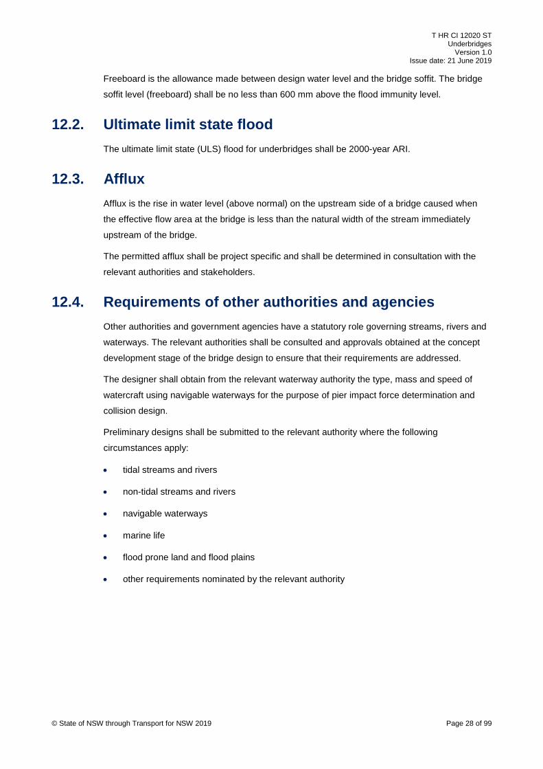
Freeboard is the allowance made between design water level and the bridge soffit. The bridge
soffit level (freeboard) shall be no less than 600 mm above the flood immunity level.
12.2. Ultimate limit state flood The ultimate limit state (ULS) flood for underbridges shall be 2000-year ARI.
12.3. Afflux Afflux is the rise in water level (above normal) on the upstream side of a bridge caused when
the effective flow area at the bridge is less than the natural width of the stream immediately
upstream of the bridge.
The permitted afflux shall be project specific and shall be determined in consultation with the
relevant authorities and stakeholders.
12.4. Requirements of other authorities and agencies Other authorities and government agencies have a statutory role governing streams, rivers and
waterways. The relevant authorities shall be consulted and approvals obtained at the concept
development stage of the bridge design to ensure that their requirements are addressed.
The designer shall obtain from the relevant waterway authority the type, mass and speed of
watercraft using navigable waterways for the purpose of pier impact force determination and
collision design.
Preliminary designs shall be submitted to the relevant authority where the following
circumstances apply:
• tidal streams and rivers
• non-tidal streams and rivers
• navigable waterways
• marine life
• flood prone land and flood plains
• other requirements nominated by the relevant authority
© State of NSW through Transport for NSW 2019 Page 28 of 99

T HR CI 12020 ST Underbridges
Version 1.0 Issue date: 21 June 2019
12.5. Scour protection Scour protection shall be designed generally in accordance with AS 5100 and Guide to Bridge
Technology Part 8 Hydraulic Design of Waterway Structures. Where a conflict exists between
the requirements of the Australian standard and the Austroads publication, AS 5100 shall take
precedence.
Scour protection shall be provided at substructure footings, including pile caps, where there is a
potential for watercourse scouring at the bridge.
The railway embankment around the abutments and wingwalls shall be provided with
appropriate scour protection where hydrological and hydraulic assessments indicate a potential
problem or where there is a history of scouring and washaways.
Adjoining landowners shall be consulted where this requirement results in the scour protection
extending outside the railway boundary.
Scour protection shall be designed in accordance with Guide to Bridge Technology Part 8
Hydraulic Design of Waterway Structures.
Scour protection will not normally be required when any one of the following criteria applies:
• the calculated ULS flood velocity of flow through the bridge opening is less than 1.5 m/s
• the calculated ULS flood velocity of flow through the bridge opening is less than 2.5 m/s
and the streambed consists of gravel or stones with 50% by weight exceeding 150 mm in
size
• the waterway bed and banks consist of sound rock or are protected by sound rock bars;
and the toe of the embankment is protected
Geometric considerations may require embankment slope protection where scour protection of
the bed is unnecessary.
Where scour protection is required downstream of the bridge, the protective system shall extend
for a distance not less than 1.5 times the height of the opening from the end of the bridge. A cut-
off extending 500 mm below the bottom of the protection or to bedrock, whichever is lesser,
shall be carried to the wing walls or up the sides of the channel to at least the serviceability limit
states level.
Scour protection shall be specifically designed for channels with a grade steeper than 1%.
Adequate provision for access shall be made for the safe inspection and maintenance of scour
protection.
© State of NSW through Transport for NSW 2019 Page 29 of 99

T HR CI 12020 ST Underbridges
Version 1.0 Issue date: 21 June 2019
The following products shall not be used as scour protection:
• grout filled fabric
• mortared rock spalls
• sandbags
13. Design loads Limit state design principles in accordance with AS 5100 shall be followed. Designs shall satisfy
both SLS and ULS requirements.
The design loads specified in this standard shall be read in conjunction with AS 5100.
13.1. Rail traffic load The loads specified in AS 5100 shall be modified in accordance with this standard.
The design rail traffic load shall be in accordance with Table 1 and Table 2 for the different rail
operating classes. Refer to ESC 200 Track System for network diagram showing the operating
classes.
Design loads associated with the traffic load (for example, dynamic load, centrifugal force,
nosing load, braking and traction forces) shall be in accordance with AS 5100 and proportioned
in accordance with the loads specified in Table 1 for main lines and Table 2 for sidings.
Table 1 – Design rail traffic load for main lines
Operating class – ESC 200 Design rail traffic
Passenger main line and light line 200LA Note 1, Note 4 and Note 5 shall apply
Mixed passenger freight main line 300LA
Freight line 300LA
Heavy freight line 350LA Note 1 shall apply
Table 2 - Design rail traffic load for sidings
Operating class – ESC 200 Design rail traffic
General freight yard 300LA Note 2 shall apply
Passenger stabling or maintenance 200LA Note 1, Note 3, Note 4 and Note 5 shall apply
Note 1: For rail traffic loads other than 300LA, all axle loads are proportioned by the
ratio of the nominated LA load divided by 300
© State of NSW through Transport for NSW 2019 Page 30 of 99

T HR CI 12020 ST Underbridges
Version 1.0 Issue date: 21 June 2019
Note 2: 50% of AS 5100.2:2017 dynamic load allowance (α) value applies
Note 3: 0% of AS 5100.2:2017 dynamic load allowance (α) value applies
Note 4: For passenger lines, work trains, occasional freight traffic, heritage steam
trains and maintenance trains (for example, track laying machine and rail sets) should
be considered in the design as nominated by the RIM
Note 5: For lines with design loadings less than 300LA, future loading requirements
should be considered
13.2. Braking and traction forces Either the empirical method or the rational method in AS 5100.2:2017 may be used for
calculating the braking and traction forces. The designer shall determine the appropriate
method for use and document the reasoning in the design report.
In applying the rational method, the characteristics of the rolling stock are required. Unless
otherwise specified in the project brief, the values in Table 3 for rolling stock characteristics
shall be used.
Table 3 – Rolling stock characteristics for use in AS 5100
Line class Rail traffic load (LA)
CoG (2) above top of rail (m)
Length (m)
Traction acceleration (m/s2)
Traction length (m)
Braking deceleration (m/s2)
Braking length (m)
Min. clear distance between trains (m)
Freight lines (3)
300 2.1 1200 0.5 110 1.2 1200 1200 (1)
Heavy coal (4)
350 2.1 1800 0.5 110 1.2 1800 1800 (1)
Passenger lines (5)
200 1.9 163 0.88 121 1.4 163 300 (1)
Note 1: Subject to confirmation by the RIM
Note 2: Centre of gravity (CoG) is the centre of gravity of the rail vehicle for design
purposes
Note 3: Based on main line freight (MF) consist defined in T HR CI 12008 ST
Note 4: Based on heavy coal (HC) consist defined in T HR CI 12008 ST
Note 5: Based on Waratah electric (WE) consist defined in T HR CI 12008 ST
13.3. Track-bridge interaction Interaction between track and bridge is present for both ballasted and direct fixation track forms.
The interaction between track and bridge results in forces in the rails and in the bridge deck and
its bearings, as well as displacements of the various bridge and track elements.
© State of NSW through Transport for NSW 2019 Page 31 of 99

T HR CI 12020 ST Underbridges
Version 1.0 Issue date: 21 June 2019
The designer shall note the effects of interaction between the track and the bridge in the design,
taking the rails, bridge deck and bearings, substructure and foundation into account.
Where required, the rails (and guard rails if installed) shall be fitted with zero longitudinal
restraint (ZLR) rail fasteners in accordance with ESC 230 Sleepers and Track Support.
Figure 1– Track-bridge interaction model
A typical track-bridge interaction model would include the following elements as shown in
Figure 1:
1. rail stiffness
2. bridge deck stiffness
3. embankment stiffness
4. rail expansion joints (if present) or use of special ZLR rail fasteners
5. track-bridge stiffness
6. support stiffness
Guidance on track-bridge interaction can be found in the following references:
• International Union of Railways UIC Code 776-2 R Design requirements for rail-bridges
based on interaction phenomena between train, track and bridge
• International Union of Railways UIC Code 774-3 R Track/bridge Interaction
Recommendations for calculations
• BS EN 16432-1 Railway applications – Ballastless track systems – Part 1: General
requirements
See Section 13.2 for requirements for braking and traction forces.
© State of NSW through Transport for NSW 2019 Page 32 of 99
T HR CI 12020 ST Underbridges
Version 1.0 Issue date: 21 June 2019
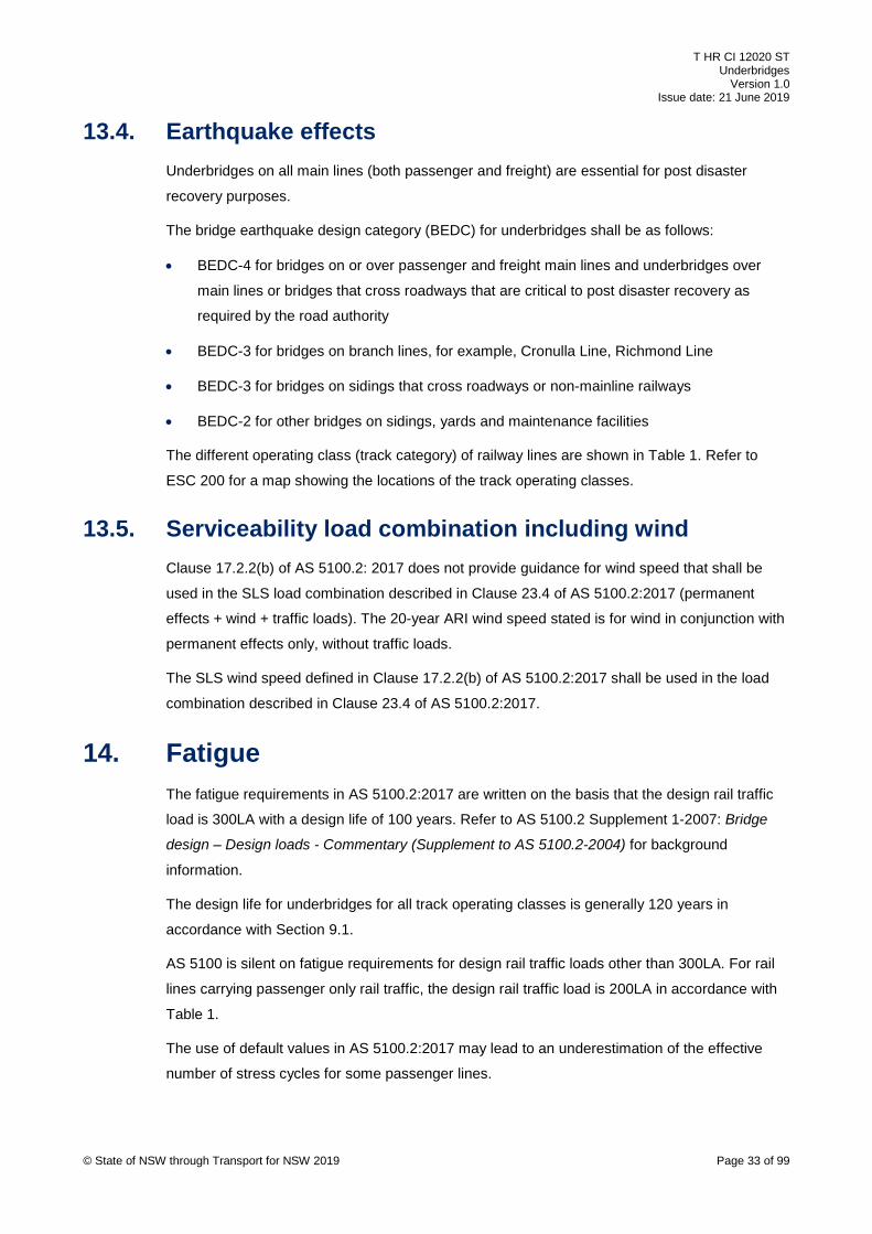
13.4. Earthquake effects Underbridges on all main lines (both passenger and freight) are essential for post disaster
recovery purposes.
The bridge earthquake design category (BEDC) for underbridges shall be as follows:
• BEDC-4 for bridges on or over passenger and freight main lines and underbridges over
main lines or bridges that cross roadways that are critical to post disaster recovery as
required by the road authority
• BEDC-3 for bridges on branch lines, for example, Cronulla Line, Richmond Line
• BEDC-3 for bridges on sidings that cross roadways or non-mainline railways
• BEDC-2 for other bridges on sidings, yards and maintenance facilities
The different operating class (track category) of railway lines are shown in Table 1. Refer to
ESC 200 for a map showing the locations of the track operating classes.
13.5. Serviceability load combination including wind Clause 17.2.2(b) of AS 5100.2: 2017 does not provide guidance for wind speed that shall be
used in the SLS load combination described in Clause 23.4 of AS 5100.2:2017 (permanent
effects + wind + traffic loads). The 20-year ARI wind speed stated is for wind in conjunction with
permanent effects only, without traffic loads.
The SLS wind speed defined in Clause 17.2.2(b) of AS 5100.2:2017 shall be used in the load
combination described in Clause 23.4 of AS 5100.2:2017.
14. Fatigue The fatigue requirements in AS 5100.2:2017 are written on the basis that the design rail traffic
load is 300LA with a design life of 100 years. Refer to AS 5100.2 Supplement 1-2007: Bridge
design – Design loads - Commentary (Supplement to AS 5100.2-2004) for background
information.
The design life for underbridges for all track operating classes is generally 120 years in
accordance with Section 9.1.
AS 5100 is silent on fatigue requirements for design rail traffic loads other than 300LA. For rail
lines carrying passenger only rail traffic, the design rail traffic load is 200LA in accordance with
Table 1.
The use of default values in AS 5100.2:2017 may lead to an underestimation of the effective
number of stress cycles for some passenger lines.
© State of NSW through Transport for NSW 2019 Page 33 of 99
T HR CI 12020 ST Underbridges
Version 1.0 Issue date: 21 June 2019
The designer shall determine the design effective number of stress cycles for passenger lines in
accordance with Section 14.1.
Bridges supporting rail lines carrying mixed passenger and freight rail traffic shall be designed
for 300LA design traffic load (also refer to Table 1) and shall comply with AS 5100 fatigue
requirements.
14.1. Fatigue requirements for bridges on passenger lines The number of trains per day may be significant on some passenger lines. These trains usually
experience high passenger occupancy during peak periods. Extended over the design life, this
combination will result in the number of fatigue cycles being significantly greater than the values
determined in accordance with AS 5100.
For bridges that convey only passenger rail traffic, the following shall apply:
• the fatigue design traffic load shall be in accordance with Section 14.1.1
• the base number of load cycles shall be in accordance with Section 14.1.2
• the number of equivalent stress cycles shall be in accordance with Section 14.1.3
• the effective number of stress cycles shall be in accordance with Section 14.1.4
14.1.1. Fatigue design traffic load for passenger lines The fatigue design traffic load for passenger lines specified in this section shall replace the
fatigue design traffic load specified in AS 5100.2:2017. It is based on the 200LA design traffic
load, modified as follows:
• the leading single 240 kN simulated locomotive axle shall be omitted
• the centre to centre spacing of the axle groups comprising four axles, shall be 20 m
• eight axle groups (total of 32 axles) shall be used, unless otherwise advised by the RIM
14.1.2. Base number of load cycles for passenger lines The base number of load cycles CT (refer to Clause 9.8.3 in AS 5100.2:2017), unless otherwise
specified by the RIM, shall be estimated as the number of current timetabled daily passenger
trains operating on the line assumed constant over the design life, multiplied by an appropriate
factor for assumed growth in the number of trains over the design life. Some passenger lines
may already be at peak saturation.
A growth factor of not less than 20% shall be applied, unless otherwise advised by the RIM.
© State of NSW through Transport for NSW 2019 Page 34 of 99
T HR CI 12020 ST Underbridges
Version 1.0 Issue date: 21 June 2019
14.1.3. Number of equivalent stress cycles for passenger lines Table 9.8.3 of AS 5100.2:2017 is based on a fatigue freight train model comprised of 60
coupled units with four axles per unit. However, electric passenger unit trains generally
comprise four, six, eight or ten coupled cars with four axles per car.
The number of equivalent stress cycles (defined in Clause 9.8.3 of AS 5100.2:2017 as nT) for
the relevant bridge components (such as stringer, cross girder, main girder, and truss or arch
members) for a passage of a single fatigue design traffic load across the bridge, shall be
determined from a stress-time spectrum analysis resulting from incrementally moving the fatigue
design load defined in Section 14.1.1 across the bridge. The incremental movement shall be
sufficiently refined to capture the maximum peak stress spectrum. Stress-time spectrum graphs
shall be provided in the design report. See Section 28.2.
14.1.4. Effective number of stress cycles for passenger lines The effective number of stress cycles, n, shall be determined using the equation in Clause 9.8.3
in AS 5100.2:2017 by substituting the calculated values for base number of load cycles
determined in accordance with Section 14.1.2, and the number of equivalent stress cycles as
determined in Section 14.1.3.
The designer shall compare the effective number of stress cycles determined using Table 9.8.4
in AS 5100.2:2017 for each component against values determined in accordance with this
section, and adopt the higher cycle values for design. The comparison calculation shall be
included in the design report (See Section 28.2).
Where any clause in AS 5100:2017 makes reference to the design (effective) number of stress
cycles (n), determined from AS 5100.2, the higher value of (n) shall be used; for example,
Clause 2.2.5 of AS 5100.5:2017.
14.1.5. Damage equivalent factor for rail bridges For bridges designed for the 200LA fatigue design traffic loading described in Section 14.1.1 of
this standard, the factor for rail bridges (λT) given in Table 13.9.2.3 of AS/NZS 5100.6:2017
Bridge design – Part 6: Steel and composite construction shall be based on the value for the
applicable number of cycles (n) determined in accordance with Section 14.1.4 of this standard.
14.2. Design life adjustment The design life for TfNSW bridges is specified in Section 9.1 and is typically 120 years.
Bridges where the base number of load cycles CT in Table 9.8.4 of AS 5100.2:2017 is used (for
example, freight line bridges) the value shall be adjusted proportionally to reflect the design life.
The design life factor is equal to the design life of the component divided by 100.
© State of NSW through Transport for NSW 2019 Page 35 of 99
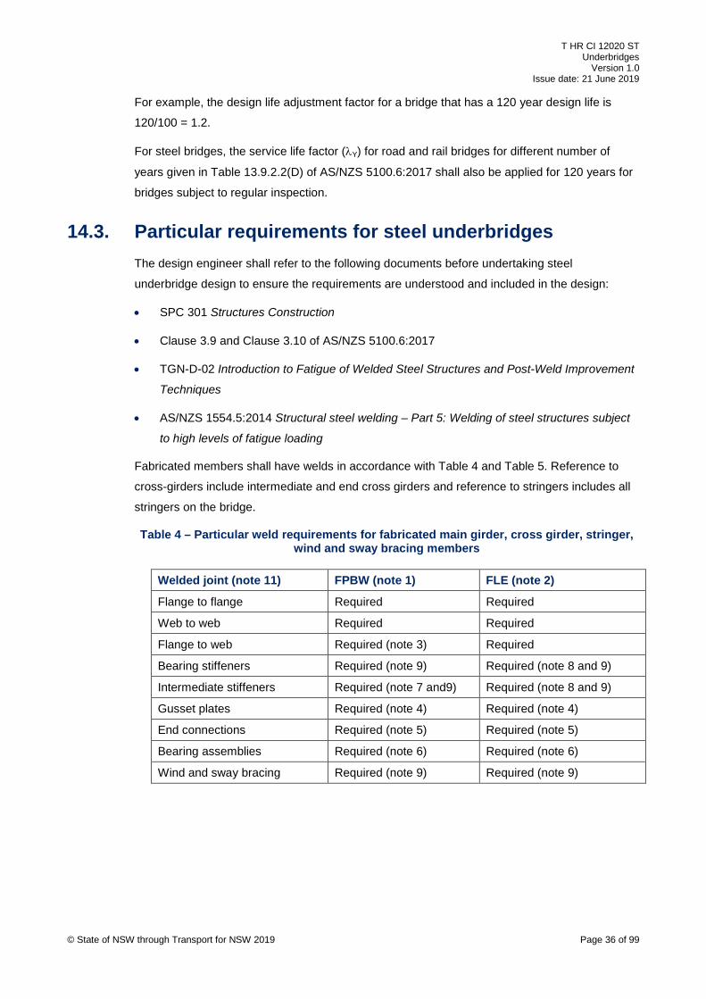
T HR CI 12020 ST Underbridges
Version 1.0 Issue date: 21 June 2019
For example, the design life adjustment factor for a bridge that has a 120 year design life is
120/100 = 1.2.
For steel bridges, the service life factor (λY) for road and rail bridges for different number of
years given in Table 13.9.2.2(D) of AS/NZS 5100.6:2017 shall also be applied for 120 years for
bridges subject to regular inspection.
14.3. Particular requirements for steel underbridges The design engineer shall refer to the following documents before undertaking steel
underbridge design to ensure the requirements are understood and included in the design:
• SPC 301 Structures Construction
• Clause 3.9 and Clause 3.10 of AS/NZS 5100.6:2017
• TGN-D-02 Introduction to Fatigue of Welded Steel Structures and Post-Weld Improvement
Techniques
• AS/NZS 1554.5:2014 Structural steel welding – Part 5: Welding of steel structures subject
to high levels of fatigue loading
Fabricated members shall have welds in accordance with Table 4 and Table 5. Reference to
cross-girders include intermediate and end cross girders and reference to stringers includes all
stringers on the bridge.
Table 4 – Particular weld requirements for fabricated main girder, cross girder, stringer, wind and sway bracing members
Welded joint (note 11) FPBW (note 1) FLE (note 2)
Flange to flange Required Required
Web to web Required Required
Flange to web Required (note 3) Required
Bearing stiffeners Required (note 9) Required (note 8 and 9)
Intermediate stiffeners Required (note 7 and9) Required (note 8 and 9)
Gusset plates Required (note 4) Required (note 4)
End connections Required (note 5) Required (note 5)
Bearing assemblies Required (note 6) Required (note 6)
Wind and sway bracing Required (note 9) Required (note 9)
© State of NSW through Transport for NSW 2019 Page 36 of 99
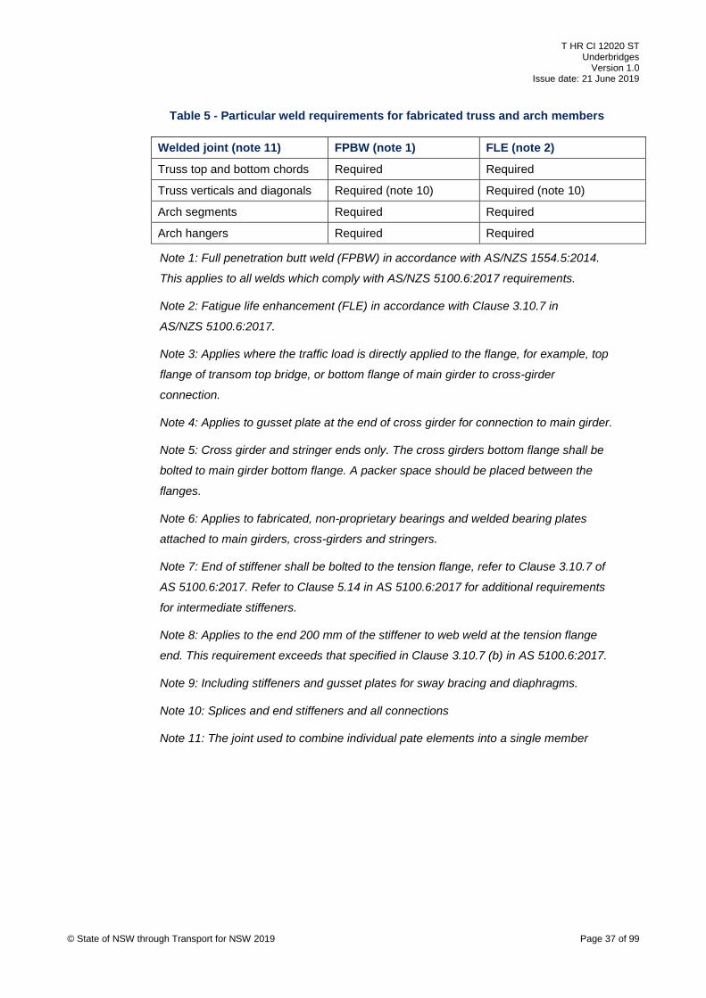
T HR CI 12020 ST Underbridges
Version 1.0 Issue date: 21 June 2019
Table 5 - Particular weld requirements for fabricated truss and arch members
Welded joint (note 11) FPBW (note 1) FLE (note 2)
Truss top and bottom chords Required Required
Truss verticals and diagonals Required (note 10) Required (note 10)
Arch segments Required Required
Arch hangers Required Required
Note 1: Full penetration butt weld (FPBW) in accordance with AS/NZS 1554.5:2014.
This applies to all welds which comply with AS/NZS 5100.6:2017 requirements.
Note 2: Fatigue life enhancement (FLE) in accordance with Clause 3.10.7 in
AS/NZS 5100.6:2017.
Note 3: Applies where the traffic load is directly applied to the flange, for example, top
flange of transom top bridge, or bottom flange of main girder to cross-girder
connection.
Note 4: Applies to gusset plate at the end of cross girder for connection to main girder.
Note 5: Cross girder and stringer ends only. The cross girders bottom flange shall be
bolted to main girder bottom flange. A packer space should be placed between the
flanges.
Note 6: Applies to fabricated, non-proprietary bearings and welded bearing plates
attached to main girders, cross-girders and stringers.
Note 7: End of stiffener shall be bolted to the tension flange, refer to Clause 3.10.7 of
AS 5100.6:2017. Refer to Clause 5.14 in AS 5100.6:2017 for additional requirements
for intermediate stiffeners.
Note 8: Applies to the end 200 mm of the stiffener to web weld at the tension flange
end. This requirement exceeds that specified in Clause 3.10.7 (b) in AS 5100.6:2017.
Note 9: Including stiffeners and gusset plates for sway bracing and diaphragms.
Note 10: Splices and end stiffeners and all connections
Note 11: The joint used to combine individual pate elements into a single member
© State of NSW through Transport for NSW 2019 Page 37 of 99

T HR CI 12020 ST Underbridges
Version 1.0 Issue date: 21 June 2019
Table 4 and Table 5 do not apply to bolted connections required for the transportation,
installation and erection of fabricated members. Welding of gusset plates for transportation shall
not be permitted.
14.3.1. Fillet welded I-sections Welded I-sections in compliance with AS/NZS 3679.2 such as commonly used welded beams
(WBs) and welded columns (WCs), do not comply with these particular requirements and the
requirements of AS/NZS 5100.6:2017 Clause 3.9.1.
WB and WC fillet welded I-sections shall not be used for members included in Table 4 and
Table 5.
14.3.2. Welding documentation All welding details and locations shall be clearly shown on the design drawings. A general
reference to welding specification is insufficient to define welding requirements.
Good practice welding details are provided in Figure 18 and Figure 19 in Appendix C.
15. Deck drainage Drainage of bridges and bridge decks shall comply with the requirements of AS 5100.1 and
T HR CI 12130 ST Track Drainage unless noted otherwise in this section.
The drainage system shall achieve the following:
• be considered when developing bridge deck arrangements
• shall include subsoil drainage systems behind abutments, at the end of approach slabs,
and behind wingwalls
• account for any recommendation from an environment assessment (Section 7) regarding
the discharge of water
• be able to be cleaned out routinely
• accommodate deck movements
• have a design life of 120 years for drainage components embedded and for fasteners to
the bridge
• have an SLS 50-year ARI
• have a minimum pipe diameter of 150 mm and comprised of rigid type pipes
• have a minimum gradient of 1 in 100 for pipes and concrete lined drainage paths
• allow for at least 10% blockage of scuppers and outlets within the bridge
© State of NSW through Transport for NSW 2019 Page 38 of 99
T HR CI 12020 ST Underbridges
Version 1.0 Issue date: 21 June 2019
• have pipeline flushing points at the start, at abrupt changes of grade or alignment and at
intervals of not more than 10 m along the bridge
• have a minimum surface fall (cross-fall or longitudinal) of 1 in 30 for jointless direct fix and
ballasted concrete deck surfaces (top of deck); see Section 11.3 for joint requirements
• accommodate long term settlements and creep of the bridge, including minimum gradients
and falls
• capture water and drain it away from the track structure at the bridge ends
• intercept water flowing downgrade from bridge approaches
• integrate the track, formation, abutments and approach slabs drainage at the bridge ends
• divert water away from, and not allow to ponding near bearings
• not be installed within the ballast profile, except where flat soffit underbridge decks are
necessary to satisfy restricted clearances and where a drainage system located external to
the bridge is not feasible (for example, a concrete through girder and slab deck bridge);
approval from the RIM shall be obtained for this arrangement
See Figure 12 and Figure 13 in Appendix C for typical details.
15.1. Decks with joints Where a bridge span crosses over areas accessed by the public, such as roadways and
footpaths, the deck drainage water shall be prevented from passing through the deck onto the
area below. This is best achieved by a jointless deck; otherwise decks with joints shall require a
waterproofing membrane.
Bridges with decks joints and crossing over areas not accessed by the public, such as
waterways or farmland, are not required to be sealed against discharge of water unless required
by project specific environmental considerations.
16. Deck waterproofing Deck waterproofing requirements shall be determined as part of the overall bridge durability.
See Section 9 for further requirements.
Waterproofing membranes shall be provided with a durable protective covering such as a
ballast mat in accordance with Section 17.
16.1. Jointed decks The selection of waterproofing membranes for jointed bridge decks shall consider specific
project conditions, such as, length of track possession time for installation.
Waterproofing membranes shall not be installed on direct fixation track bridge decks. © State of NSW through Transport for NSW 2019 Page 39 of 99

T HR CI 12020 ST Underbridges
Version 1.0 Issue date: 21 June 2019
Where deck joints are required to be sealed, waterproof joint seals shall be used. Deck
drainage system shall be in accordance with Section 15.
16.2. Jointless decks Waterproofing membranes shall not be installed on jointless decks unless required under the
project durability plan.
17. Ballast mats Ballast mats are generally not needed for new underbridges that comply with relevant TfNSW
standards. The selection of a ballast mat as a protective covering for waterproofing membranes
and deck joints shall take into account the project conditions. For example, ballast mats may be
required to protect existing concrete bridge decks from impact damage.
The ballast mats shall comply with the following:
• the requirements in T HR TR 00192 ST Ballast
• have a proven minimum service life of 20 years in conditions comparable to the project
conditions
• shall not be installed on jointless decks unless required for noise or vibration control or
track reasons
• shall extend over ballasted approach slabs
18. Earthworks Earthworks associated with underbridge construction shall be designed in accordance with
T HR CI 12110 ST Earthworks and Formation and T HR CI 12111 SP Earthworks Materials.
19. Services and utilities Services owned by TfNSW such as, high voltage, low voltage, signalling, communications, or
non-rail utilities owned by other authorities such as, telephone, water supply, power and gas
may be required to be supported on an underbridge.
Reference shall also be made to T HR CI 12190 ST Service Installations within the Rail Corridor
for general requirements.
The following requirements shall apply to services on underbridges:
• the designer shall consult with the relevant authorities and provide special ducts and
troughing for current and future services and utilities where appropriate
• services and utilities shall be segregated where necessary; for example, power and
signalling, and shall comply with the relevant Australian standards and TfNSW standards © State of NSW through Transport for NSW 2019 Page 40 of 99
T HR CI 12020 ST Underbridges
Version 1.0 Issue date: 21 June 2019
• the location and fixing of the service troughing and utility ducts shall be designed so that
future access to the underbridge structure for inspection and maintenance is not impeded
• the utility ducts and troughing shall be designed and located so that future inspection and
maintenance does not impede rail operations
• service ducts and troughing shall be located to comply with ESC 215 Transit Space
• where service troughing and utility ducts are attached to a bridge walkway, they shall be
positioned such that they do not infringe the safe working area or create a trip or other
safety hazard
See Figure 12 to Figure 17 in Appendix C for typical details.
20. Collision protection of underbridges Underbridges spanning over and underbridge piers adjacent to roadways and other railways
shall be protected against collision impact in accordance with AS 5100 and the requirements of
this standard.
20.1. Underbridges over and adjacent to roadways The clearance from the underbridge deck soffit to the roadway shall be in accordance with
Section 10.1.
Where the clearance is less than specified in Section 10.1, underbridge impact protection in
accordance with TMC 312 Underbridge Impact Protection shall be provided.
20.1.1. Concrete deck spans Underbridges with concrete decks spanning over roadways, shall have a protection angle as
follows:
• protection angle shall be not less than 150 x 150 EA and hot dipped galvanised
• extends the full length of the girder in segment lengths
• has segment lengths not greater than 3 m with 10 mm gaps
• cast into the bottom edge of the outer member, irrespective of clearance provided or
whether or not an underbridge protection beam is provided
Example of typical details is provided in CV0191355 Precast concrete girders for underbridges,
10.6 m pretensioned girder – Concrete details and CV0191356 Reinforcement Details
© State of NSW through Transport for NSW 2019 Page 41 of 99

T HR CI 12020 ST Underbridges
Version 1.0 Issue date: 21 June 2019
20.1.2. Steel deck spans Steel underbridges over roadways that have clearance less than that specified in Section 10.1,
shall have the bottom flange of the outermost girders stiffened to allow for accidental impact
from over height vehicles in addition to underbridge protection beam requirements.
The stiffening shall comprise the addition of a bottom flange cover plate that extends over the
length of the approach traffic lanes. This shall provide an additional 50% of flange area that is
needed for strength, and shall project not less than 50 mm past the bottom flange in the
direction of approaching traffic. Additional vertical stiffing may be required to reduce distortion of
the bottom flange in the event of accidental impact.
20.1.3. Piers and abutments Underbridge piers and abutments located within 10 m of the centre line of a roadway and at risk
from errant vehicle collision, shall be protected from collision from road traffic by suitable
barriers located between the road and railway corridor. The designer shall determine the
performance level of the protection barrier required.
Piers and abutments shall be designed for the collision load specified in AS 5100.2:2017.
20.2. Underbridges over and adjacent to rail tracks Underbridge pier or support elements shall not be located between tracks or on platforms,
unless approved by the Lead Civil Engineer, ASA.
There shall be no reduction in the collision load requirements specified in AS 5100 for piers on
platforms.
This requirement also applies to refurbishment and upgrade works including any alterations to
the piers or columns, and increases in loads on the structure or expansion of the structure. See
Section 31 for other requirements.
21. Derailment containment devices Derailment containment devices are used for the following reasons:
• to limit the lateral movement of a derailed train on an underbridge by keeping derailed or
derailing bogies or wheels tracked parallel to and in close proximity to the running rails
• to prevent a train from falling off the side of a bridge
• to prevent impact of derailed train with a major structural element of the bridge
All new underbridges shall have derailment containment devices installed as required in this
standard.
© State of NSW through Transport for NSW 2019 Page 42 of 99

T HR CI 12020 ST Underbridges
Version 1.0 Issue date: 21 June 2019
One form of derailment containment device only shall be installed at a bridge location except
where otherwise specified in this standard, or where required by the RIM.
Bridge end protection shall be provided in accordance with AS 5100.2:2017 and Section 21.5.
21.1. Approved configurations Approved derailment containment devices on underbridges are:
• derailment kerbs
• guard rails (refer to T HR CI 12071 ST Guard Rails for requirements)
• deflection barriers for through spans
Table 6 contains approved configurations for derailment containment device installations for
different bridge structure types and is applicable for all span lengths.
Table 6 – Approved configurations for derailment containment devices
Structure type Single guardrail
Twin guardrails
Derailment kerbs
Deflection barriers
Steel through girder, truss or arch span with concrete deck (ballast or direct fixed track)
Not approved Not approved Not approved Mandatory
Steel through girder, truss or arch span with transoms
Not approved Mandatory Not applicable Mandatory
Concrete through girder span and deck (ballast or direct fixed track)
Not approved Approved (note 3)
Approved (note 3)
Approved (note 1 and note 2)
Concrete through truss, arch span with concrete deck (ballast or direct fixed track)
Not approved Not approved Not approved Mandatory
Transom top deck span
Not approved Mandatory Not applicable Not applicable
Ballast top deck span Not approved Approved Approved (note 2)
Not applicable
Direct fixation deck span
Approved (note 3)
Approved Approved (note 2)
Not applicable
Note 1: Not applicable where main girders are designed for the derailment collision
load in accordance with AS 5100.2:2017
Note 2: Preferred arrangement
Note 3: Requires approval from Lead Civil Engineer, ASA
© State of NSW through Transport for NSW 2019 Page 43 of 99

T HR CI 12020 ST Underbridges
Version 1.0 Issue date: 21 June 2019
21.2. Deck spans Deck spans are bridge decks where all of the structural elements are positioned below the
track. Typical examples of deck spans include the following:
• precast concrete planks, girders or slabs supporting ballasted or direct fixation track
• steel girders with concrete deck supporting ballasted or direct fixation track
Specific requirements are stated in Section 21.2.1 and Section 21.2.2.
21.2.1. Ballast and direct fixation track deck spans Derailment containment devices are not required on inner tracks on multiple track ballast top
and direct fix bridges with full width decks which are capable of supporting a derailed train; for
example, where a bridge has three tracks, the centre track does not require derailment
containment devices.
21.2.2. Transom top deck spans Guard rails are the only derailment containment device applicable for transom top deck spans.
21.3. Through spans Through spans are bridge decks where the main structural members are positioned outside of,
and extend above, the rail track. Typical examples of through spans include the following:
• truss and arch bridges spans
• steel or concrete girder spans
Specific requirements for through span bridges are described in Sections 21.3.1 to
Section 21.3.3.
21.3.1. Concrete girder through spans For main girders that are designed to resist the collision loads directly, no additional derailment
containment is required within the bridge structure. See Figure 14 and Figure 15 in Appendix C
for details.
21.3.2. Steel through spans with concrete deck
The following additional requirements for the deflection barrier shall apply:
• The deflection barrier shall be constructed from concrete and integral with the concrete
deck.
• For through girders, the vertical face of the barrier adjacent to the track shall extend
towards the track at least 150 mm horizontally from the inside vertical face of the steel © State of NSW through Transport for NSW 2019 Page 44 of 99
T HR CI 12020 ST Underbridges
Version 1.0 Issue date: 21 June 2019
main girder flange, or the stiffener, whichever projects the furthest, so that the flange is
protected.
• The top of the concrete barrier may terminate at the underside of girder top flange in order
to allow inspection and reduce maintenance. The top corner profile of the concrete barrier
should be slightly chamfered down away from the underside of the girder flange.
Note: Clause 11.4.4.2 of AS 5100.2:2017 requires the deflection barrier to extend to
the top of the uppermost primary element where the height of the girder is less than
2 m above rail.
• Careful detailing is required to ensure inspection can be undertaken and minimal
maintenance of steel elements.
See Figure 16 and Figure 17 in Appendix C for illustrative details for steel through girder spans.
21.3.3. Steel transom top through spans New steel transom top through spans (with steel cross-girders and stringers without a concrete
deck) shall have both guardrails and deflection barriers installed in accordance with Table 6,
due to the higher risk associated with this type of bridge.
Deflection barriers comprised of steel post and railings are acceptable.
21.4. Bridges with hazard on one side only Where a hazard exists only on one side of the bridge, derailment containment devices may be
provided for that side only, subject to the following:
• twin guardrails can be installed where the hazard only exists on one side of the track if
alternative derailment containment arrangements are inappropriate
• on single track bridges, containment devices are required to protect both sides
• approval from the RIM
• see Table 6 for approved configurations for derailment containment devices
21.5. Protection of ends of through spans AS 5100 requirements for the protection of the end of through structures are specified differently
in two parts of the standard as follows, and are contradictory to each other creating ambiguity:
• Clause 15.3.6 of AS 5100.1:2017 refers to Clause 11.4.2.3 or Clause 11.4.2.4 of
AS 5100.2:2017 or whichever is applicable
• Clause 11.4.4.3 of AS 5100.2:2017 refers to Clause 11.4.4.2 of AS 5100.2:2017, which in
turn refers to Clause 11.4.3 of AS 5100.2:2017
© State of NSW through Transport for NSW 2019 Page 45 of 99

T HR CI 12020 ST Underbridges
Version 1.0 Issue date: 21 June 2019
Support element collision loads Clause 11.4.2.3 and Clause 11.4.2.4 of AS 5100.2:2017 shall
apply, as applicable.
Where the through span height is less than 2 m above the rail level, these applicable support
element design collision loads shall apply at the top end of the barrier or deflection wall.
Clause 11.4.3 of AS 5100.2:2017 shall also apply.
22. Bridge ends The design of new underbridges shall provide for the stability and compaction of the track on
bridge approaches. This applies to bridges of all types and track form.
Bridge approaches shall be designed to achieve the following:
• provide a transition between flexible and rigid track support systems
• maintain the integrity of the ballast profile at the end of the bridge
• maintain the sleeper support across the interface
22.1. Configuration The selection of the most appropriate configuration for each location is influenced by the
following factors:
• the type of track form, that is, ballast or direct fixation
• traffic density, tonnage and speed
• feasibility of implementation
• whether the work is part of new construction, upgrading or maintenance activity
• ground conditions
22.2. General requirements The following general requirements apply to all underbridges:
• approach slabs shall be installed on all new underbridges
• earthworks and backfill at abutments installed in accordance with relevant TfNSW
standards
• ballast retention walls where required by the project or by the RIM
• transition in accordance with Section 23
© State of NSW through Transport for NSW 2019 Page 46 of 99

T HR CI 12020 ST Underbridges
Version 1.0 Issue date: 21 June 2019
22.3. Approach slabs Approach slabs comprise a concrete structural element, either precast or cast-in situ. Approach
slabs shall satisfy the following general requirements:
• approach slabs shall be ballasted unless otherwise permitted in this standard
• approach slabs shall be supported by the abutment at the bridge end and by the track
formation at the other end and may be partially suspended in between
• approach slabs can be used on approaches to ballast top, direct fixed and transom top
bridges
• all approach slabs shall have exterior kerbs and the kerb type shall be the same as on the
bridge deck
• the width of the approach slab shall not be less than the width of the bridge deck
• the kerbs on approach slabs shall be aligned vertically and horizontally with the kerbs on
the bridge deck at the bridge end
• the distance between inside faces of kerb on the approach slab shall increase away from
the bridge, that is flare outwards, at an angle not exceeding 20 degrees
• where bridges are located on a skew, the track end of the approach slab shall be shaped to
be perpendicular to the track, to avoid rocking of the sleepers
• minimum length shall be 4 m measured at any point from the abutment end
• longitudinal joints in the approach slab shall not be located under the track and shall
comply with the joint requirements as for the bridge deck
• for multiple track bridges, longitudinal joints where needed, shall be positioned midway
between tracks
• crossfall of the approach slab shall be made compatible with the bridge deck and the track
formation
• subsurface drainage shall be provided at the interface between the end of the approach
slab and the approach formation at both ends of the bridge
• the approach slab shall be supported on an elastomeric bearing strip on the bridge
abutment and restrained from lateral and longitudinal movement by grade 316 stainless
steel dowels
• provision for approach slab rotation shall be included in dowel and bearing strip , with a
layer of compressible material under the approach slab near the abutment end, to allow for
formation settlement
© State of NSW through Transport for NSW 2019 Page 47 of 99
T HR CI 12020 ST Underbridges
Version 1.0 Issue date: 21 June 2019
22.3.1. Ballasted track deck spans Approach slabs for ballasted track bridges shall be installed with the top surface of the slab at
formation level (bottom of ballast level) at the approach end and at the same level of the bridge
deck level at the bridge end.
The slope of the approach slab shall follow the grade of the bridge and track formation with
provision for subsurface track drainage at the end of the approach as required.
See Figure 21 in Appendix C for details.
22.3.2. Direct fixation track deck spans The approach slab at a non-skewed bridge end shall be fully ballasted.
For a skewed bridge end, the end of the approach slab supported at the abutment shall also be
direct fixation for an appropriate length to enable the first sleeper supported on ballast to be
installed square to the track. The minimum length of ballasted track on the approach shall be
4 m.
The preferred grade of the approach slab is falling away from the abutment end where practical,
to allow for a variable ballast depth to provide gradually increasing track stiffness. In such
situations the following applies:
• the track formation shall be graded down to meet the end of the approach slab
• the maximum ballast depth shall not exceed that permitted in ESC 230
Where it is not practical to grade the approach slab to fall away from the abutment, the
approach slab shall follow the grade of the bridge deck and the track formation.
See Figure 22 to Figure 24 in Appendix C for details.
22.3.3. Through spans Through spans which incorporate inner kerbs on the bridge deck shall have the kerbs extended
along the approach slabs.
The distance between the inside faces of the kerbs on the approach slab shall be splayed
outwards starting at the bridge end. The splay angle shall not exceed 20 degrees.
Deflection barriers to protect the ends of the through girders from head on collision may be
integrated into the approach slab. The approach slab may require additional foundation support
to resist the collision loads in accordance with AS 5100.
See Section 21.5 for further requirements for protecting the ends of through spans.
© State of NSW through Transport for NSW 2019 Page 48 of 99
T HR CI 12020 ST Underbridges
Version 1.0 Issue date: 21 June 2019
22.4. Ballast retention walls Ballast retention walls may be required at bridge ends with narrow formation width to prevent
loss of the ballast shoulder from the track.
Ballast retaining walls for new underbridges shall be constructed from concrete. CV0115011
provides details for standard precast reinforced concrete ballast wall.
23. Transitions Transition zones are locations where a railway track exhibits abrupt changes in vertical stiffness
between ballasted track on a grade to track on a more rigid bridge deck that occurs at bridge
abutments.
Transition regions usually require more frequent track maintenance due to the increase in
dynamic forces resulting in settlement.
The objective of an effective track transition is to avoid abrupt change in track stiffness. The
change in stiffness shall be gradual. The track transition shall be considered in combination with
the approach slab requirements in Section 13.3 and Section 22.3.
General guidance for transition requirements can be found in the following documents:
• International Union of Railways UIC Code 776-2 R
• International Union of Railways UIC Code 774-3 R
• BS EN 16432-1
Track transitions in accordance with the requirements in Section 23.1 and Section 23.2 are
deemed to satisfy the objective for an effective track transition.
Where the designer does not adopt these requirements, the objective for the transition between
ballasted track and a track on rigid bridge deck shall be satisfied, and approved by the RIM.
23.1. Ballast top bridges Ballast top bridges that have approach slabs in accordance with the requirements of this
standard are not required to have special track transition, unless for project specific
requirements, or required by the RIM.
For existing ballast top bridges without approach slabs, the RIM shall determine whether
stiffening of the track formation at the bridge ends is required; see Section 31.3.
© State of NSW through Transport for NSW 2019 Page 49 of 99
T HR CI 12020 ST Underbridges
Version 1.0 Issue date: 21 June 2019
23.2. Direct fixation track and transom top spans A track transition arrangement shall be installed at the ends of all new direct fixation and
transom top bridges.
A model track transition arrangement between ballasted track and direct fixed bridges, including
transom top bridges, has been used for a number of years in the TfNSW Metropolitan Heavy
Rail Network. This model arrangement has proven to provide satisfactory performance and
eliminated track maintenance issues related to bridges.
The model track transition arrangement at both ends of the bridge comprises the following
sleeper arrangement in the sequence listed commencing from the bridge end:
c. ten special concrete bearers with Alternative 1 rail plates in accordance with CV0168626
and CV0168627, placed immediately at the end of the bridge on a ballasted approach slab,
or immediately after a direct fixation approach slab
d. six standard concrete sleepers with SA47 rail pads replacing the standard HDPE rail pads
e. standard concrete sleepers with standard HDPE rail pads
Details of this standard transition are shown in CV0558906 and in Figure 26 in Appendix C.
23.3. Intermediate rail support on ballast walls The maximum spacing between the centres of the first sleeper off the bridge approach and the
first transom or direct fixed rail support on the bridge, should be limited to 600 mm or as
permitted in ESC 230 Sleepers and Track Support.
At locations where rail support centres in excess of the maximum spacing cannot be avoided,
an intermediate support shall be installed on the ballast wall, enabling the rail support spacing to
be within the maximum spacing in order to reduce the forces at the bridge end.
Reference shall be made to CV0162590 All Lines - Standard Intermediate Rail Support at
Bridge Ballast Walls for detailed requirements. This configuration includes the use of a resilient
rubber pad on top of the ballast wall, which provides vertical support to the rail when deflecting
under wheel load.
For skewed ballast walls, custom intermediate rail supports may be required and shall be
designed by the AEO and approved by the RIM.
Bridges with a track transition in accordance with Section 23.2, the intermediate rail support
may be provided by an approved resilient rail plate (for example, Delkor Alternative 1) fixed
directly on top of the ballast wall; see Figure 22 and Figure 24 in Appendix C.
Refer to CV0558906 for typical details.
© State of NSW through Transport for NSW 2019 Page 50 of 99
T HR CI 12020 ST Underbridges
Version 1.0 Issue date: 21 June 2019
24. Earthing and bonding In electrified areas the design of underbridges and associated elements such as walkways,
refuges, safety and protection screens, shall provide for earthing and bonding of metallic
components in order to mitigate touch potential hazards and corrosion of steel.
Note: Electrified areas cover the section of railway provided with 1500 V dc overhead
wiring, nominally bounded by Hamilton in the north, Kiama in the south, Bowenfels in
the west and Glenlee in the south west.
The design requirements for earthing and bonding of all underbridges in the electrified areas
shall comply with the requirements set out in TN 016: 2015 Overbridges and footbridges –
Earthing and bonding requirements and the requirements of the Lead Electrical Engineer, ASA.
25. Overhead wiring structures OHWSs shall not be installed on underbridges where possible.
OHWSs shall be located at least 3 m clear from the ends of culverts.
Where OHWS placement on a bridge cannot be avoided, the bridge structure shall be
configured so that OHW supports and registration equipment are attached in accordance with
the following requirements:
• the preferred location for OHW support structures is on the bridge superstructure rather
than the substructure to facilitate inspection and maintenance
• the final location for OHWS shall be approved by the RIM
• the deck shall be locally widened and kerbs thickened as necessary to accommodate the
support baseplates
• clearance requirements shall be in accordance with Section 10.5
• earthing and bonding and isolation shall be provided in accordance with electrical
standards referenced in Section 24
• special attention to electrical isolation is required for metallic walkways where fitted around
OHWS
26. Nameplates and plaques All new and upgraded underbridges shall be fitted with nameplates. Nameplates stencilling and
plaques shall be in accordance with ESC 300 and TMC 300.
The following information shall be provided on the nameplate:
• the kilometrage of the bridge
© State of NSW through Transport for NSW 2019 Page 51 of 99
T HR CI 12020 ST Underbridges
Version 1.0 Issue date: 21 June 2019
• the year of construction
27. Advertising signs Advertising signage supported on underbridges shall be in accordance with the following
requirements:
• the design of advertising signs attached to underbridges shall be in accordance with
AS 5100
• for installing advertising signage on existing bridges, the bridge shall be assessed to
determine if it has sufficient structural capacity to carry the additional load from the
advertising sign
• signs shall be fixed to existing structural members only after the designer has assessed
that the fixing will not have an adverse effect on the structure
• signs shall not adversely affect the structural integrity of the bridge
• signs and associated support elements and fixings shall not be welded to existing
underbridges
• the preferred method of attachment of advertising signs on existing bridges is by clamping
brackets, for new bridges attachments may be incorporated into the structure
• fixing of post-installed anchors in concrete elements shall be in accordance with
AS 5216:2018 Design of post installed anchors and cast in fasteners in concrete
• steel reinforcement detection shall be carried out prior to anchor installation and anchor
locations chosen to avoid damage to steel reinforcement
• signs shall not create an obstruction that causes water to pond or debris to accumulate
anywhere on the underbridge
• signs shall not be a factor in the deterioration of the bridge
• fixings and ladders for the sign maintenance shall not infringe the clear walking space of
walkways and the clear space of refuges
• signs and attachments shall not block sight lines of track and operational personnel
• signs shall not permit unauthorised access to the rail corridor
• signs and attachments shall not prevent access for inspection and maintenance of the
bridge; including the part of the structure immediately behind the sign
Additional information on advertising signs is contained in the NSW Department of Planning and
Environment 2017, Transport Corridor Outdoor Advertising and Signage Guidelines.
© State of NSW through Transport for NSW 2019 Page 52 of 99
T HR CI 12020 ST Underbridges
Version 1.0 Issue date: 21 June 2019
27.1. Fatigue design of advertising signs Advertising sign supporting members and attachments shall be designed for the fatigue limit
state in accordance with Clause 24.4 of AS 5100.2:2017.
28. Documentation The design of all new underbridges shall be fully documented and relevant information retained
by the RIM. Section 28.1 to Section 28.4 provides the required documentation details.
28.1. Investigation reports Investigation reports shall include, but not be limited to, the following:
• bridge, track (line and kilometrage) and location description
• condition inspections and assessments
• bridge capacity assessment for existing underbridges; refer to T HR CI 12008 ST for
requirements
• site geotechnical investigation, survey, services searches
• hydrologic and hydraulic investigations, refer to T HR CI 12130 ST report requirements
• heritage impact assessment
• design options
• cost estimates and options evaluation
• safety in design and hazard log
• recommendations
28.2. Detailed design reports Detailed design reports shall include, but not be limited to, the following:
• bridge, track (line and kilometrage) and location description
• design standards
• design inputs and assumptions
• material and section properties, and so on
• design methodology and analysis methods and software used
• summary of design loads, member design actions and member design capacities
• fatigue design, stress-time spectrum graphs for passenger line bridges
© State of NSW through Transport for NSW 2019 Page 53 of 99
T HR CI 12020 ST Underbridges
Version 1.0 Issue date: 21 June 2019
• heritage and environmental issues
• hydrologic, hydraulic design, refer to T HR CI 12130 ST report requirements
• drainage design
• durability plan
• technical maintenance plans
• safety in design, risk and hazard logs
• design construction drawings
• technical specifications
28.3. Construction drawings Construction drawings shall comply with T MU MD 00006 ST Engineering Drawings and CAD
Requirements.
Drawings shall record the design criteria and any other information that is relevant to ensuring
that the new structure can be constructed and maintained in accordance with the design.
Numbering of bridge members shall be in accordance with ESC 300.
The relevant safety in design aspects shall be documented on the construction drawings.
28.3.1. As-built construction drawings As-built construction drawings shall be prepared and submitted to the RIM at the completion of
the construction works.
28.4. Technical specifications The designer shall prepare a complete technical specification for the bridge.
The technical specification for underbridge construction shall be in accordance with SPC 301
Structures Construction.
RMS QA specifications are referenced in SPC 301. The designer shall supply the information
that is required by the RMS specifications.
© State of NSW through Transport for NSW 2019 Page 54 of 99

T HR CI 12020 ST Underbridges
Version 1.0 Issue date: 21 June 2019
29. Construction Construction constraints, particularly under live operating conditions and track possession, shall
be taken into account in bridge design.
Particular requirements include the following:
• Clearances shall take into account of transit space requirements, safe working and
construction plant and equipment.
• Bearings, joints and adjacent structure elements shall be designed to provide sufficient
access and clearances for the inspection, maintenance and replacement of the bearings
and joints.
• Jacking points shall be provided on the superstructure and on the bearing shelf to facilitate
the replacement of bearings. Sufficient vertical clearance between the underside of the
superstructure and bearing shelf shall be provided for proved jacking systems.
• Adequate clearance shall be provided to allow for inspection and maintenance under
normal train operations.
• Access to all parts of the bridge including substructure and embankment scour protection,
for inspections, maintenance activities such as re-painting, in accordance with specific
requirements stated in the durability plan.
29.1. Temporary works Temporary works associated with the bridge construction that have a potential to impact rail
safety shall be an integral part of the design and documented as part of the bridge construction
drawings.
The use of specialised plant and equipment, such as jacking, stressing, formwork, falseworks
and props shall be fit for purpose and installed in accordance with the manufacturer’s written
instructions.
30. Maintenance Maintenance requirements for new underbridges shall be determined in consultation with and in
agreement by the RIM.
The following maintenance requirements shall be taken into account:
• The maintenance requirements shall be specified in the technical maintenance plan for the
bridge.
• In most cases, MN A 00100 Civil Technical Maintenance Plan and ESC 302 Defect Limits
will apply. It may be necessary to document site-specific maintenance requirements, where
the standard technical maintenance plan (TMP) does not address specific maintenance © State of NSW through Transport for NSW 2019 Page 55 of 99
T HR CI 12020 ST Underbridges
Version 1.0 Issue date: 21 June 2019
requirements. Refer to T MU AM 01003 ST Development of Technical Maintenance Plans
for details.
• Anti-graffiti paints shall be used on underbridges in areas within the corridor where a risk
assessment has determined a high risk of graffiti, subject to approval by the RIM. The
requirements for anti-graffiti coatings shall be nominated by the RIM.
• Anti-graffiti coatings shall comply with APAS Specification 1441/1 Permanent Graffiti
Barrier.
• The durability requirement shall be in accordance with Section 9 and the project durability
plan if applicable.
31. Existing bridges Existing bridges are usually refurbished or upgraded at some stage in their asset life cycle.
Existing bridges shall be assessed in accordance with T HR CI 12008 ST.
Timber and masonry may be used in the like-for-like replacement of components in an existing
bridge.
Rehabilitation and strengthening of existing bridges shall comply with AS 5100.8:2017.
31.1. Bridge refurbishment For the purpose of this standard, refurbishment means like-for-like replacement, rehabilitation or
repair of bridge components to provide the equivalent load capacity, functionality and
performance as the original component.
Repair methods and procedures documented in TMC 302 Structures Repair may be specified
by the AEO in refurbishment design works. Where repair methods are not adequately detailed
in TMC 302, the AEO shall develop and document appropriate repair methods and materials.
31.1.1. Design life The design life of refurbishment works shall be determined by the AEO based on the
consideration of whole-of-life costs, and approved by the RIM.
The design life for the refurbishment works shall not be less than 20 years.
31.2. Bridge upgrade For the purpose of this standard, upgrade means the following:
• replacement, modification or strengthening of components of the bridge to provide an
increased load capacity, functionality or performance over that of the original component
• lengthening or widening of the structure for network expansion © State of NSW through Transport for NSW 2019 Page 56 of 99
T HR CI 12020 ST Underbridges
Version 1.0 Issue date: 21 June 2019
For substandard existing bridge openings, a risk assessment in accordance with Section 5.1,
which includes the bridge upgrade requirements in Section 31.2, shall determine feasibility of
the widening shall be submitted to the RIM for approval.
31.2.1. Compliance with new bridge requirements For bridges where the estimated cost of the proposed upgrade work is greater than 35% of the
replacement cost of the existing structure with a new, compliant structure, the entire bridge shall
be upgraded to comply with the requirements for new underbridges.
For works that do not meet this criterion, only the proposed works need to be undertaken and
general upgrading of the structure is not required.
The partial or complete replacement of the structure could be a more sustainable option than
upgrading the existing structure.
Upgrade works adjacent to an existing structure shall consider the need to develop or replace
the existing structures in the future.
31.2.2. Design life Elements of the bridge which are replaced, for example, superstructure, shall have a design life
in accordance with Section 9.1.
31.2.3. Substructure assessment
Where the superstructure of an underbridge is proposed to be replaced, the capacity of the
substructure shall be assessed in accordance with T HR CI 12008 ST. The assessment shall
include settlement analysis and global and local stability analysis.
For bridges with substructure not satisfying the requirements of T HR CI 12008 ST for a rating
factor greater than unity against the relevant operating consist traffic live load for the line class,
the substructure shall be strengthened to the design traffic live load specified in Section 13.
A cost benefit analysis shall be undertaken to determine whether the substructure shall be
strengthened to meet the requirements of T HR CI 12008 ST for either of the following:
• the operating consist traffic load
• the design traffic live load
Otherwise it should be replaced to meet the requirements of the design traffic live load as
described in Section 13.
© State of NSW through Transport for NSW 2019 Page 57 of 99
T HR CI 12020 ST Underbridges
Version 1.0 Issue date: 21 June 2019
31.3. Bridge approaches Approach slabs or engineered fill shall be installed behind abutments where the backfill is
disturbed to a depth greater than 200 mm below capping level as part of any refurbishment
works.
Where upgrade of existing bridges is carried out, and where the abutments are retained with no
disturbance to the fill behind the abutment, a track transition in accordance with Section 23 may
be installed, as approved by the RIM.
31.3.1. Ballast retention walls
For existing bridges where ballast retaining walls at the ends of existing bridges are required,
steel post and guard railing may be used to retain the ballast to avoid undermining the track and
for quick installation.
Details of a post and guard railing ballast retention system is shown in Figure 29 in Appendix C
for guidance.
31.3.2. Engineered backfill
For existing bridges which have track maintenance issues at bridge ends, the formation
immediately behind the abutments may be re-constructed in layers of selected compacted fill
reinforced with geogrid as an alternative to an approach slab.
Engineered backfill shall be as follows:
• comply with T HR CI 12110 ST
• provide drainage below the compacted fill material
• not be used to replace approach slabs for new underbridges
Typical details are provided in Figure 28 in Appendix C.
31.3.3. Geocells Geocells may also be used to construct the formation immediately behind the bridge, and shall
be designed for each specific bridge site and submitted for approved by the RIM.
Typical details are provided in Figure 27 in Appendix C.
© State of NSW through Transport for NSW 2019 Page 58 of 99
T HR CI 12020 ST Underbridges
Version 1.0 Issue date: 21 June 2019
31.4. Collision protection of existing underbridges Existing underbridges that are at risk from collision impact shall be assessed in accordance with
the requirements in Section 5.1 to determine the extent of protection required.
If an existing underbridge is proposed to be modified or extended (for example, convert an
existing pier or abutment in to a common pier), or another track installed nearby, then collision
loading from any adjacent track shall be considered in the design.
31.4.1. Protection of underbridges over roadways An increased risk of collision applies to many existing underbridges over roadways where the
clearances and protection requirements are less than current requirements.
Clearances shall be determined by a survey of the road and soffit levels.
Where clearances are not in accordance with the minimum requirements specified in
Section 10.1, the following applies:
• low clearance signs shall be provided in accordance with AS 1742.2 Manual of uniform
traffic control devices – Traffic control devices for general use and AS 1743 Road signs –
Specifications
• a risk assessment in accordance with Section 5 shall determine the extent of protection
required
• underbridges determined to be at a high risk of collision shall be provided with an
appropriate form of protection against damage
• approved protection configurations shall be in accordance with TMC 312 Underbridge
Impact Protection
• loads on protection beams shall be in accordance with AS 5100
• collision loads and barrier protection shall be in accordance with Section 20.1
31.4.2. Protection of underbridges over rail tracks
Where an existing underbridge over other rail tracks is modified, the risk of derailment collision
shall be assessed against the risk criteria defined in Section 5.
Other collision load requirements shall be in accordance with Section 20.
32. Culverts and buried structures Section 32.1 to Section 32.5 covers box culverts and pipe culverts that cross the rail corridor
and are generally installed below the track formation level.
© State of NSW through Transport for NSW 2019 Page 59 of 99
T HR CI 12020 ST Underbridges
Version 1.0 Issue date: 21 June 2019
32.1. Box culverts Clause 9.1 in AS 5100.3: 2017 Bridge design - Part 3: Foundation and soil-supporting structures
states precast reinforced concrete box culverts shall be designed in accordance with
AS 1597.2, for the sizes specified in that standard.
Culverts and buried structures that do not conform to the requirements of AS 1597.2 shall be
designed in accordance with AS 5100 and all relevant sections of this standard.
Traffic loads shall be in accordance with Section 32.3.
Attention is drawn to Clause G5 and Table G4 in AS 1597.2-2013. The values in the table for
average intensity of design live load (kPa), particularly at shallower depths, are not
representative of the distribution method, the design load of 300LA, the dynamic load allowance
(DLA) and load factors described in Clause G5. The designer shall calculate the average
intensity of live load, rather than adopt the values in Table G4.
The value of DLA in accordance with AS 1597.2 has a maximum value of 1.0, where as in
AS 5100.2:2017, the value for DLA (α) is calculated based on a characteristic length of half the
culvert span, with a maximum value of 0.67. Unless otherwise approved, the value for DLA (α)
shall be as specified in AS 1597.2.
Culvert structures with ballast bearing directly on top of the culvert, for example, box culverts,
shall be provided with ballast kerbs in accordance with Section 11.6.1.
Derailment containment devices are not required on culverts unless they form part of a project
specific requirement or as required by the RIM.
Box culvert waterway and flood design shall be in accordance with Section 12.
32.2. Pipe culverts Pipe culverts shall be supplied and installed in accordance with T HR CI 12130 ST Track
drainage.
Pipe culvert waterway and flood design shall be in accordance with Section 12.
Pipe culverts shall be designed for effects of traffic loads in accordance with Section 32.3.
32.3. Traffic loads Culverts, including pipes, extending across the rail corridor shall be designed for rail traffic load
in accordance with Section 13.1 for the full length across the rail corridor.
Railway load dynamic effects (impact factor) for complying precast concrete pipes shall be in
accordance with AS/NZS 3725 Design for installation of buried concrete pipes, which varies
linearly from 1.4 (α=0.4) at 0.3 m depth to 1.0 (α=0.0) at 3.5 m depth or greater (where the
© State of NSW through Transport for NSW 2019 Page 60 of 99

T HR CI 12020 ST Underbridges
Version 1.0 Issue date: 21 June 2019
depth is measured from the top of rail). Railway load dynamic effects for other complying pipes
shall be in accordance with AS 5100.
32.4. Durability The durability and design life requirements for culverts shall be in accordance with
T HR CI 12002 ST.
32.5. Extension and repair of existing culverts Where an existing culvert is extended across the rail corridor to accommodate additional tracks
or access roads, the following design load shall be applied:
• railway load in accordance with Section 13
• access road load will be based on the type of traffic that will be using the road
The load shall be in accordance with T HR CI 12200 ST Access Roads, unless otherwise
advised by the local RIM.
Refer to CV0048002 Extension for Standard Brick Arch Oviform Culverts for details on
extension of brick arch oviform culverts.
Culvert extension for brick arches shall be in accordance with TMC 313 Brick arch culvert
extension and repair.
Repairs to pipe culverts may also be undertaken using proprietary lining systems in accordance
with T HR CI 12130 ST.
For substandard existing culvert openings, a risk assessment in accordance with Section 5.1,
which includes the upgrade requirements in Section 31.2, shall determine feasibility of the
extension and submitted to the RIM for approval.
33. Decommissioning and disposal Decommissioning is the final process of withdrawing an asset from operational service on the
network.
Disposal is the process of physically removing an asset from the network; for example,
demolition of an underbridge followed by removal and recycling.
The decommissioning and disposal of an asset is the final stage of the asset life cycle. Proper
planning for this phase of the life cycle is an integral part of the strategic life cycle process.
The process for the disposal of an underbridge, usually undertaken in conjunction with a
replacement, shall include the following:
• justification (safety, financial and so on) for disposal of the asset
© State of NSW through Transport for NSW 2019 Page 61 of 99
T HR CI 12020 ST Underbridges
Version 1.0 Issue date: 21 June 2019
• confirmation of stakeholder engagement regarding the proposed action; such engagement
shall include all relevant authorities, but not be limited to heritage; local, state and federal
government; RIM and environmental body consultation
• agreement from all stakeholders to the decommissioning or disposal of the existing
underbridge
After decommissioning and disposal, the asset database shall be updated by the RIM to reflect
network changes.
Ninety-five per cent of construction and demolition waste by weight of the decommissioned
asset shall be diverted from landfill.
© State of NSW through Transport for NSW 2019 Page 62 of 99
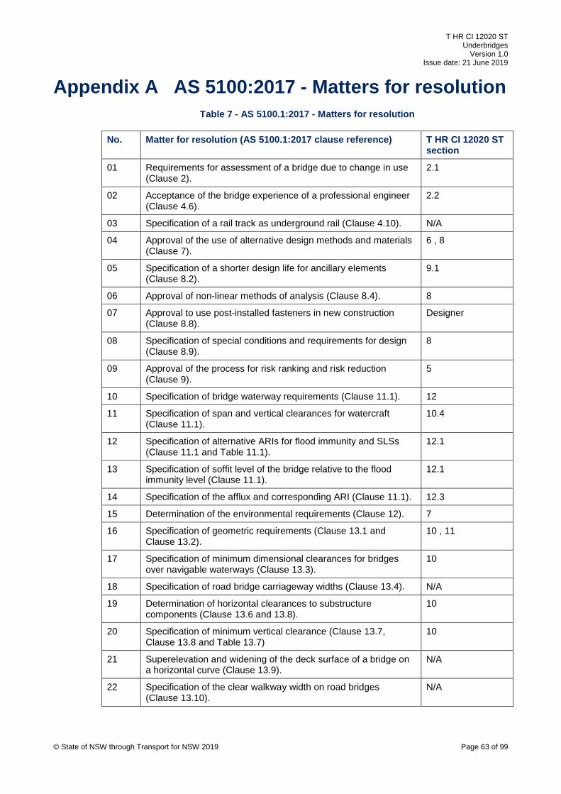
T HR CI 12020 ST Underbridges
Version 1.0 Issue date: 21 June 2019
Appendix A AS 5100:2017 - Matters for resolution Table 7 - AS 5100.1:2017 - Matters for resolution
No. Matter for resolution (AS 5100.1:2017 clause reference) T HR CI 12020 ST section
01 Requirements for assessment of a bridge due to change in use (Clause 2).
2.1
02 Acceptance of the bridge experience of a professional engineer (Clause 4.6).
2.2
03 Specification of a rail track as underground rail (Clause 4.10). N/A
04 Approval of the use of alternative design methods and materials (Clause 7).
6 , 8
05 Specification of a shorter design life for ancillary elements (Clause 8.2).
9.1
06 Approval of non-linear methods of analysis (Clause 8.4). 8
07 Approval to use post-installed fasteners in new construction (Clause 8.8).
Designer
08 Specification of special conditions and requirements for design (Clause 8.9).
8
09 Approval of the process for risk ranking and risk reduction (Clause 9).
5
10 Specification of bridge waterway requirements (Clause 11.1). 12
11 Specification of span and vertical clearances for watercraft (Clause 11.1).
10.4
12 Specification of alternative ARIs for flood immunity and SLSs (Clause 11.1 and Table 11.1).
12.1
13 Specification of soffit level of the bridge relative to the flood immunity level (Clause 11.1).
12.1
14 Specification of the afflux and corresponding ARI (Clause 11.1). 12.3
15 Determination of the environmental requirements (Clause 12). 7
16 Specification of geometric requirements (Clause 13.1 and Clause 13.2).
10 , 11
17 Specification of minimum dimensional clearances for bridges over navigable waterways (Clause 13.3).
10
18 Specification of road bridge carriageway widths (Clause 13.4). N/A
19 Determination of horizontal clearances to substructure components (Clause 13.6 and 13.8).
10
20 Specification of minimum vertical clearance (Clause 13.7, Clause 13.8 and Table 13.7)
10
21 Superelevation and widening of the deck surface of a bridge on a horizontal curve (Clause 13.9).
N/A
22 Specification of the clear walkway width on road bridges (Clause 13.10).
N/A
© State of NSW through Transport for NSW 2019 Page 63 of 99
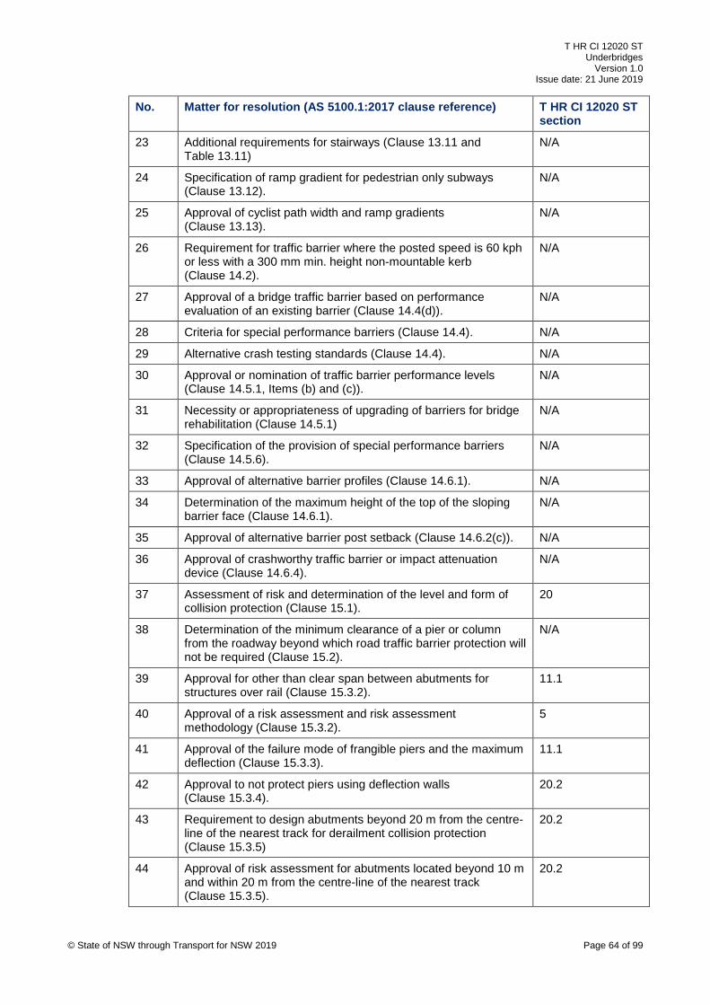
T HR CI 12020 ST Underbridges
Version 1.0 Issue date: 21 June 2019
No. Matter for resolution (AS 5100.1:2017 clause reference) T HR CI 12020 ST section
23 Additional requirements for stairways (Clause 13.11 and Table 13.11)
N/A
24 Specification of ramp gradient for pedestrian only subways (Clause 13.12).
N/A
25 Approval of cyclist path width and ramp gradients (Clause 13.13).
N/A
26 Requirement for traffic barrier where the posted speed is 60 kph or less with a 300 mm min. height non-mountable kerb (Clause 14.2).
N/A
27 Approval of a bridge traffic barrier based on performance evaluation of an existing barrier (Clause 14.4(d)).
N/A
28 Criteria for special performance barriers (Clause 14.4). N/A
29 Alternative crash testing standards (Clause 14.4). N/A
30 Approval or nomination of traffic barrier performance levels (Clause 14.5.1, Items (b) and (c)).
N/A
31 Necessity or appropriateness of upgrading of barriers for bridge rehabilitation (Clause 14.5.1)
N/A
32 Specification of the provision of special performance barriers (Clause 14.5.6).
N/A
33 Approval of alternative barrier profiles (Clause 14.6.1). N/A
34 Determination of the maximum height of the top of the sloping barrier face (Clause 14.6.1).
N/A
35 Approval of alternative barrier post setback (Clause 14.6.2(c)). N/A
36 Approval of crashworthy traffic barrier or impact attenuation device (Clause 14.6.4).
N/A
37 Assessment of risk and determination of the level and form of collision protection (Clause 15.1).
20
38 Determination of the minimum clearance of a pier or column from the roadway beyond which road traffic barrier protection will not be required (Clause 15.2).
N/A
39 Approval for other than clear span between abutments for structures over rail (Clause 15.3.2).
11.1
40 Approval of a risk assessment and risk assessment methodology (Clause 15.3.2).
5
41 Approval of the failure mode of frangible piers and the maximum deflection (Clause 15.3.3).
11.1
42 Approval to not protect piers using deflection walls (Clause 15.3.4).
20.2
43 Requirement to design abutments beyond 20 m from the centre-line of the nearest track for derailment collision protection (Clause 15.3.5)
20.2
44 Approval of risk assessment for abutments located beyond 10 m and within 20 m from the centre-line of the nearest track (Clause 15.3.5).
20.2
© State of NSW through Transport for NSW 2019 Page 64 of 99

T HR CI 12020 ST Underbridges
Version 1.0 Issue date: 21 June 2019
No. Matter for resolution (AS 5100.1:2017 clause reference) T HR CI 12020 ST section
45 Approval of alternative thickness for abutments located within 10 m from the centre-line of the nearest track (Clause 15.3.5).
Lead Civil Engineer, ASA
46 Approval not to use deflection walls in the specified locations (Clause 15.3.6).
20.2
47 Specification of the length of a deflection wall (Clause 15.3.6). 20
48 Determination of the requirements for concrete wall support in rail tunnels (Clause 15.3.7).
N/A
49 Required level of protection for structures on platforms (Clause 15.3.7).
20
50 Determination of the watercraft to be used for the pier collision forces, pier protection, or pier-redundant superstructures (Clause 15.4).
12.4
51 Alternative barrier arrangements for the outside edge of a pedestrian or cyclist path (Clause 16.2.2).
N/A
52 Requirements for pedestrian protection barriers over electrified rail (Clause 16.3).
5.4
53 Requirement for protection screens (Clause 16.4). 5.4
54 Minimum height of a protection screen (Clause 16.4(c)(i)). 5.4
55 Alternative vertical clearances for a protection screen (Clause 16.4(c)(iv)).
5.4
56 Requirement for noise barriers (Clause 17). 7.3.1
57 Requirements for drainage of road and rail bridges (Clause 18.1).
15
58 Permission for water to run onto the bridge (Clause 18.1). 15
59 Waterproofing of rail bridges (Clause 18.3). 16
60 Permission to attach utility services (Clause 20). 19
61 Approval and provisions for method of attachment of utility services (Clause 20(a)).
19
62 Determination that a bridge shall be designed for the effects of fire (Clause 22).
7.2
63 Determination of the fire time-temperature curve (Clause 22(a)). 7.2
64 Approval of the design life for a sign or light structure (Clause 23.2).
27
Table 8 – AS 5100.2:2017 - Matters for resolution
No. Matter for resolution (AS 5100.2:2017 clause reference) T HR CI 12020 ST section
01 Approval to vary any of the loads set out in this standard, provided the provisions of AS 5100.1:2017 are complied with (Clause 1.2)
13
02 Design loads and factors for road bridges carrying rail traffic (Clause 7.4)
N/A
© State of NSW through Transport for NSW 2019 Page 65 of 99
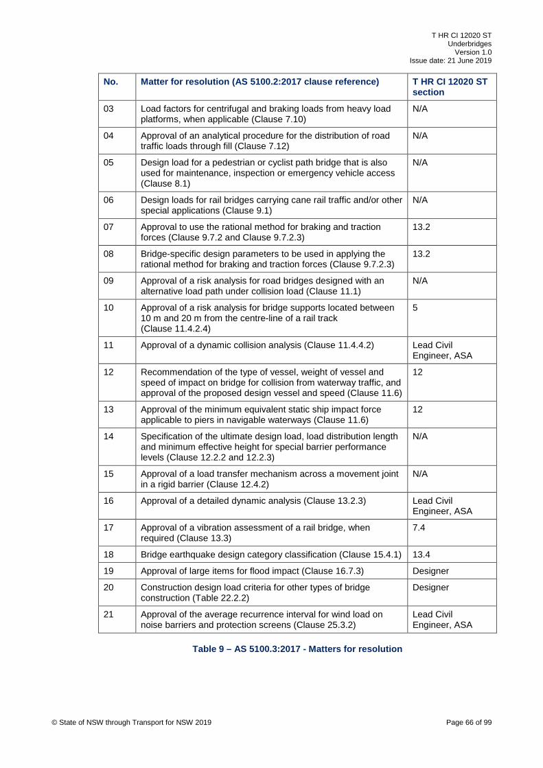
T HR CI 12020 ST Underbridges
Version 1.0 Issue date: 21 June 2019
No. Matter for resolution (AS 5100.2:2017 clause reference) T HR CI 12020 ST section
03 Load factors for centrifugal and braking loads from heavy load platforms, when applicable (Clause 7.10)
N/A
04 Approval of an analytical procedure for the distribution of road traffic loads through fill (Clause 7.12)
N/A
05 Design load for a pedestrian or cyclist path bridge that is also used for maintenance, inspection or emergency vehicle access (Clause 8.1)
N/A
06 Design loads for rail bridges carrying cane rail traffic and/or other special applications (Clause 9.1)
N/A
07 Approval to use the rational method for braking and traction forces (Clause 9.7.2 and Clause 9.7.2.3)
13.2
08 Bridge-specific design parameters to be used in applying the rational method for braking and traction forces (Clause 9.7.2.3)
13.2
09 Approval of a risk analysis for road bridges designed with an alternative load path under collision load (Clause 11.1)
N/A
10 Approval of a risk analysis for bridge supports located between 10 m and 20 m from the centre-line of a rail track (Clause 11.4.2.4)
5
11 Approval of a dynamic collision analysis (Clause 11.4.4.2) Lead Civil Engineer, ASA
12 Recommendation of the type of vessel, weight of vessel and speed of impact on bridge for collision from waterway traffic, and approval of the proposed design vessel and speed (Clause 11.6)
12
13 Approval of the minimum equivalent static ship impact force applicable to piers in navigable waterways (Clause 11.6)
12
14 Specification of the ultimate design load, load distribution length and minimum effective height for special barrier performance levels (Clause 12.2.2 and 12.2.3)
N/A
15 Approval of a load transfer mechanism across a movement joint in a rigid barrier (Clause 12.4.2)
N/A
16 Approval of a detailed dynamic analysis (Clause 13.2.3) Lead Civil Engineer, ASA
17 Approval of a vibration assessment of a rail bridge, when required (Clause 13.3)
7.4
18 Bridge earthquake design category classification (Clause 15.4.1) 13.4
19 Approval of large items for flood impact (Clause 16.7.3) Designer
20 Construction design load criteria for other types of bridge construction (Table 22.2.2)
Designer
21 Approval of the average recurrence interval for wind load on noise barriers and protection screens (Clause 25.3.2)
Lead Civil Engineer, ASA
Table 9 – AS 5100.3:2017 - Matters for resolution
© State of NSW through Transport for NSW 2019 Page 66 of 99

T HR CI 12020 ST Underbridges
Version 1.0 Issue date: 21 June 2019
No. Matter for resolution (AS 5100.3:2017 clause reference) T HR CI 12020 ST section
01 Design requirements for foundations for OHWSs (Clause 1.2) 25
02 Detailed method and formulae to be used for the design of geotechnical or structural elements (Clause 1.2)
Designer
03 Supervision of site investigation (Clause 1.6) Designer
04 Extent and coverage of preliminary and design investigation (Clause 1.6)
Designer
05 Minimum number of boreholes (Clause 1.6.2) Designer
06 Selection of the geotechnical strength reduction factors (Clause 2.3.5)
Designer
07 Testing requirements if design by prototype testing (Clause 2.6) Designer
08 Requirement for consideration of future development (Clause 2.8)
8
09 Other durability criteria (Clause 4.1) 9
10 Use of treated and untreated timber (Clause 4.2) 6
11 Requirements for prevention of corrosion of reinforcement (Clause 4.3)
9
12 Acceptance of rates of corrosion for steel surface (Clause 4.4). 9
13 Requirements to minimize corrosion effects on stray currents (Clause 4.4)
24.1
14 Durability requirements of other materials (Clause 4.5) 6.1, 9
15 Design requirements for durability of materials used in shallow foundations (Clause 5.3.6)
9
16 Requirements for structural design and detailing for shallow footings (Clause 5.4)
Designer
17 Requirements for materials and construction for shallow foundations (Clause 5.5)
6
18 Bridges essential for post-disaster recovery (Clause 6.3.2) 13.4
19 Use of timber piles (Clause 6.3.2). 6
20 Requirements for durability of materials used (Clause 6.3.4) 9
21 Requirements for structural design and detailing for construction of piles (Clause 6.4)
Designer
22 Requirements for materials and construction for piles (Clause 6.5.1)
6
23 Requirements for testing of piles (Clause 6.6) Designer
24 Design requirements for durability of anchorages and anchorage components (Clause 7.3.6)
9, 29
25 Requirements for materials and construction for anchorages (Clause 7.4)
6, 29
26 Requirements for method of installation and on-site assessment tests for anchorages (Clause 7.6.1)
Designer
27 Proof load test for anchors (Clause 7.6.2) 29
28 Requirements for anchorage suitability tests (Clause 7.6.3) 29 © State of NSW through Transport for NSW 2019 Page 67 of 99

T HR CI 12020 ST Underbridges
Version 1.0 Issue date: 21 June 2019
No. Matter for resolution (AS 5100.3:2017 clause reference) T HR CI 12020 ST section
29 Requirements for anchorage acceptance tests (Clause 7.6.4) 29
30 Requirements for the design of retaining walls and abutments (Clause 8.1)
8
31 Acceptance of geotechnical strength reduction factor for retaining walls and abutments (Clause 8.3.1)
Designer
32 Design requirements for durability of retaining walls and abutments (Clause 8.3.5)
9
33 Requirements for structural design and detailing for retaining walls and abutments (Clause 8.4)
Designer
34 Requirements for materials and construction for retaining walls and abutments (Clause 8.5)
6
35 Approval of drainage system for retaining walls and abutments (Clause 8.6)
Designer
36 Requirements for the design of buried structures (Clause 9.1) 31.5
37 Design requirements for the durability of materials (Clause 9.3.3) 6, 9
38 Requirements for structural design and detailing for buried structures (Clause 9.4)
Designer
39 Requirements for materials and construction for buried structures (Clause 9.5)
6, 9
Table 10 - AS 5100.6:2017 - Matters for resolution
No. Matter for resolution (AS 5100.6:2017 clause reference) T HR CI 12020 ST section
1 Requirements for bridges, members and materials specified in Items (a) to (d) of Clause 1.2, and for new and unusual bridges.
6
2 Design requirements for structural elements using non-ferrous metals (Clause 1.3)
6
3 Requirements for steels for machined parts and for uses in other than structural member or elements (Clause 2.2.4)
6
4 Requirements for structures, members and materials (Clause 1.2)
6
5 Requirements for the fatigue design assessment method (Clause 13.6)
Designer
Table 11 – AS 5100.8:2017 - Matters for resolution
No. Matter for resolution (AS 5100.8:2017 clause reference) T HR CI 12020 ST section
01 Life expectancy of the particular rehabilitation or strengthening method and materials (Clause 2.1)
31
02 Design live loading including the use of bridge specific assessment live loading (BSALL) (Clause 2.3.1, Clause 2.3.2 and Paragraph E1, Appendix E)
31
© State of NSW through Transport for NSW 2019 Page 68 of 99
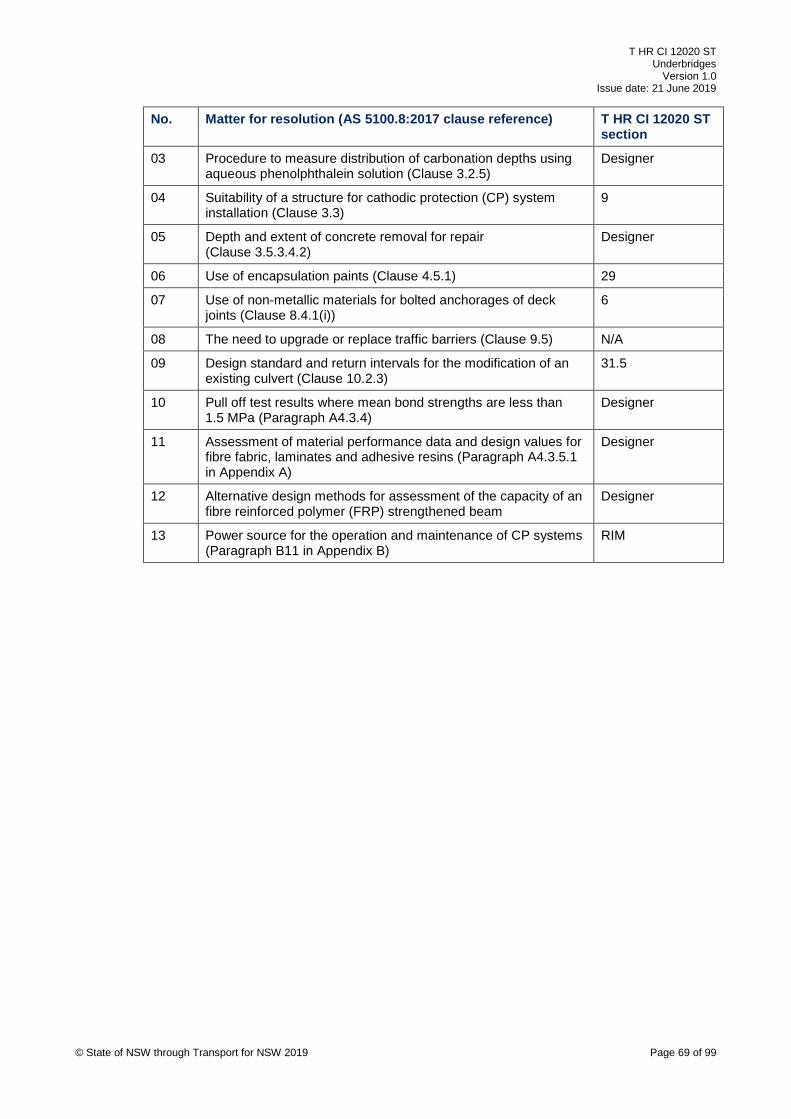
T HR CI 12020 ST Underbridges
Version 1.0 Issue date: 21 June 2019
No. Matter for resolution (AS 5100.8:2017 clause reference) T HR CI 12020 ST section
03 Procedure to measure distribution of carbonation depths using aqueous phenolphthalein solution (Clause 3.2.5)
Designer
04 Suitability of a structure for cathodic protection (CP) system installation (Clause 3.3)
9
05 Depth and extent of concrete removal for repair (Clause 3.5.3.4.2)
Designer
06 Use of encapsulation paints (Clause 4.5.1) 29
07 Use of non-metallic materials for bolted anchorages of deck joints (Clause 8.4.1(i))
6
08 The need to upgrade or replace traffic barriers (Clause 9.5) N/A
09 Design standard and return intervals for the modification of an existing culvert (Clause 10.2.3)
31.5
10 Pull off test results where mean bond strengths are less than 1.5 MPa (Paragraph A4.3.4)
Designer
11 Assessment of material performance data and design values for fibre fabric, laminates and adhesive resins (Paragraph A4.3.5.1 in Appendix A)
Designer
12 Alternative design methods for assessment of the capacity of an fibre reinforced polymer (FRP) strengthened beam
Designer
13 Power source for the operation and maintenance of CP systems (Paragraph B11 in Appendix B)
RIM
© State of NSW through Transport for NSW 2019 Page 69 of 99
T HR CI 12020 ST Underbridges
Version 1.0 Issue date: 21 June 2019
Appendix B BTDs The following is a list of RMS BTDs, current at the time of publication of this standard, relevant
for the design of underbridges. The designer shall check for the currency of this list:
• CBE 1988/08 Provision of Curtain Walls
• CBE 1990/09 Weld Category – Fabricated Steelwork
• CBE 1991/06 Permanently Cased Piles – Driving Shoe Details
• CBE 1993/03 Socket Inserts for Precast Concrete Girders
• CBE 1994/05 Drainage of Voids in Bridge Deck
• CBE 1994/07 Mass of Girders
• CBE 1996/04 Driven Piles
• CBE 1997/01 Variability of Concrete Properties
• CBE 1997/10 Use of Brand Names
• CBE 1998/08 Bridge Bearings – Design for Maintenance or Replacement
• CBE 1998/15 Multi Span Plank Bridges with Link Slabs Guidelines for Bearing Selection
• BDI 1980/03 Bearing Levels
• BDI 1980/11 Provision of Lifting Lugs on Steel Girders
• BDI 1984/06 Provision of Drainage on Bridge Kerb
• BDI 1985/06 Bent on Site Reinforcing Bars
• BDI 1985/07 Anchor Bolts
• BDI 1986/02 Design for Continuous Superstructures
• BPC 2001/01 Replacement of Chief Bridge Engineer’s Circulars
• BPC 2003/02 Rev1 Waterproofing Membranes for Concrete Bridge Decks
• BPC 2003/04 Use of Proprietary Expanded Metal Construction Joints and Shear Keys
• BPC 2004/08 Inspection of Modular Bridge Expansion Joints and Control of Noise
• BPC 2004/11 Strategies for Enhancing the Durability of Post-Tensioned Concrete Bridges
• BPC 2005/04 Rev1 Pot Bearing Attachment Plates
• BPC 2005/05 Use of Steel Fibre Reinforced Reactive Powder Concrete (‘Ductal’) in RTA
Works
• BPC 2005/06 Bird Nesting in Bridge Abutments & Box Girders
© State of NSW through Transport for NSW 2019 Page 70 of 99
T HR CI 12020 ST Underbridges
Version 1.0 Issue date: 21 June 2019
• BPC 2005/08 Welding of Bridges
• BPC 2006/03 RTA Approval of Proprietary Bridging Systems
• BPC 2006/05 Pipes and Conduits for Bridgeworks
• BPC 2007/05 Design of Integral Bridges
• BTD 2007/09 Soil-arch Structures
• BTD 2007/10 Restraint of Longitudinal Reinforcement in Columns
• BTD 2007/11 Horizontal Reinforcement for Crack Control in Walls and Wall Type Piers
• BTD 2007/12 Design for Replacement of Bridge Bearings
• BTD 2007/13 Durability of Steel Piles in Contact with Acid Sulfate Soils
• BTD 2008/02 Access for Inspection, Monitoring and Repair or Replacement of Bridge
Components
• BTD 2008/05 Splicing of Steel Girders Using Bolts
• BTD 2008/08 Provision of Conduits in Bridge Traffic Barriers
• BTD 2008/09 Link Slabs for Precast Pretensioned Concrete Girder Bridges
• BTD 2008/10 Bridge Deck Joints
• BTD 2008/11 Lists of RTA Approved Bridge Components and Systems
• BTD 2008/12 Provisions for Concrete Structures in Acid Sulfate Soils
• BTD 2008/13 Provisions for Future Cathodic Protection of Reinforced Concrete Bridges
• BTD 2010/03 Pretensioned Bridge Members – Concrete Transfer Strength Requirements
• BTD 2011/02 Use of CFA Piles on Bridges
• BTD 2011/03 Skid-Resistant Treatments for Bridge Deck Joints
• BTD 2011/05 Minimum Restraint Capacity for Superstructures
• BTD 2011/06 Provisions for the Design of Super-T Girder Bridges
• BTD 2011/08 Testing of Cast-in-Place Concrete Piles
• BTD 2013/01 Design of Precast Reinforced Concrete Box Culverts
• BTD 2014/02 Durability Plan for Bridgeworks and Other Structures
• BTD 2018/01 Bridge bearings
© State of NSW through Transport for NSW 2019 Page 71 of 99

T HR CI 12020 ST Underbridges
Version 1.0 Issue date: 21 June 2019
Appendix C Typical bridge details Typical bridge details for various types of bridges are shown in Figure 2 to Figure 29.
200 mm min typ.
Derailment kerb
TOR
Ballast kerb with guard rails
JOINTLESS DECK
2300 mm min
© State of NSW through Transport for NSW 2019 Page 72 of 99
Figure 2 – Ballasted straight track on bridge deck with alternative ballast kerb and derailment kerb
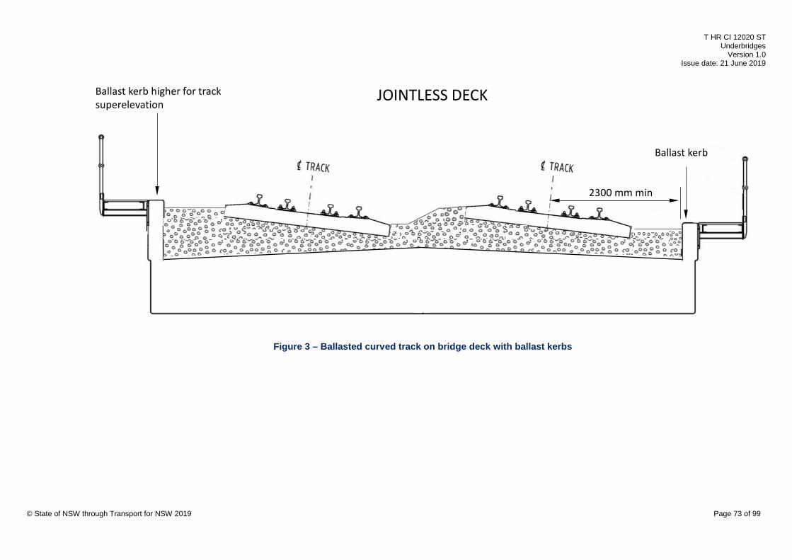
T HR CI 12020 ST Underbridges
Version 1.0 Issue date: 21 June 2019
Ballast kerb higher for track superelevation
2300 mm min
Ballast kerb
JOINTLESS DECK
© State of NSW through Transport for NSW 2019 Page 73 of 99
Figure 3 – Ballasted curved track on bridge deck with ballast kerbs
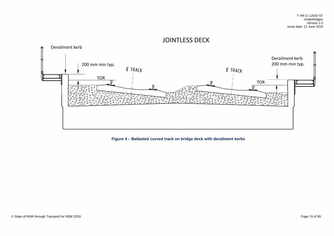
T HR CI 12020 ST Underbridges
Version 1.0 Issue date: 21 June 2019
200 mm min typ.
TOR
Derailment kerb
Derailment kerb 200 mm min typ.
TOR
JOINTLESS DECK
© State of NSW through Transport for NSW 2019 Page 74 of 99
Figure 4 – Ballasted curved track on bridge deck with derailment kerbs
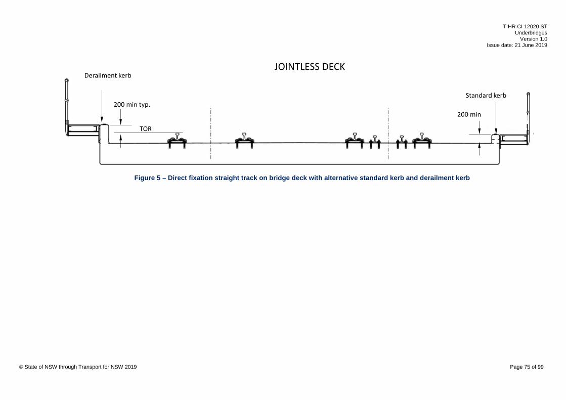
T HR CI 12020 ST Underbridges
Version 1.0 Issue date: 21 June 2019
JOINTLESS DECK
TOR
200 min typ.
Derailment kerb
200 min
Standard kerb
© State of NSW through Transport for NSW 2019 Page 75 of 99
Figure 5 – Direct fixation straight track on bridge deck with alternative standard kerb and derailment kerb
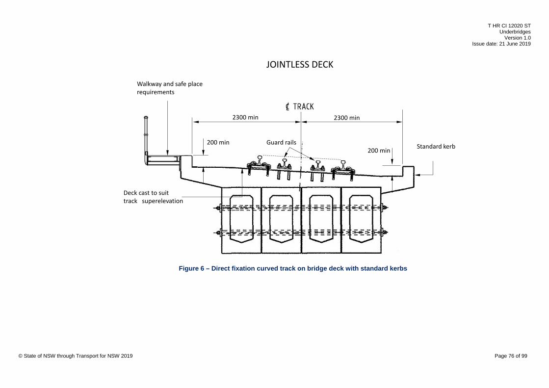
T HR CI 12020 ST Underbridges
Version 1.0 Issue date: 21 June 2019
2300 min 2300 min
200 min200 min
Guard rails
Walkway and safe place requirements
Deck cast to suit track superelevation
Standard kerb
JOINTLESS DECK
© State of NSW through Transport for NSW 2019 Page 76 of 99
Figure 6 – Direct fixation curved track on bridge deck with standard kerbs

T HR CI 12020 ST Underbridges
Version 1.0 Issue date: 21 June 2019
Derailment kerb200 min200 min
Deck cast to suit track superelevation
2300 min 2300 min
TORTOR
Walkway and safe place requirements
JOINTLESS DECK
© State of NSW through Transport for NSW 2019 Page 77 of 99
Figure 7 – Direct fixation curved track on bridge deck with derailment kerbs

T HR CI 12020 ST Underbridges
Version 1.0 Issue date: 21 June 2019
200 mm min typ.
Derailment kerb Deck joint
TOR
Ballast mat and waterproof membrane
Transverse stressing
Precast slab/beam deck
JOINTED DECK
Ballast kerb and guard rails
2300 mm min
© State of NSW through Transport for NSW 2019 Page 78 of 99
Figure 8 – Ballasted straight track on bridge deck with alternative ballast kerb and derailment kerb

T HR CI 12020 ST Underbridges
Version 1.0 Issue date: 21 June 2019
Ballast kerb higher for track superelevation
Deck joint
Ballast mat and waterproof membrane
2300 mm min
Ballast kerb
2300 mm min
Precast slab/beam deck
Transverse stressing
JOINTED DECK
© State of NSW through Transport for NSW 2019 Page 79 of 99
Figure 9 – Ballasted curved tracks on bridge deck with ballast kerbs
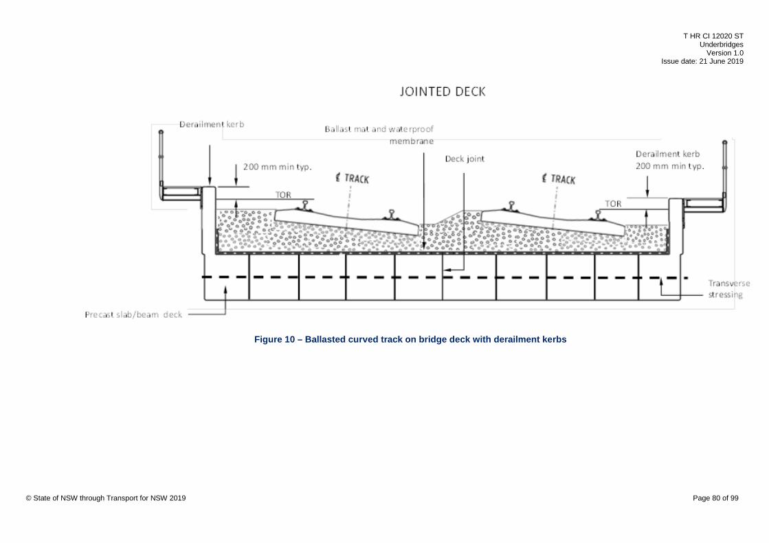
T HR CI 12020 ST Underbridges
Version 1.0 Issue date: 21 June 2019
© State of NSW through Transport for NSW 2019 Page 80 of 99
Figure 10 – Ballasted curved track on bridge deck with derailment kerbs

T HR CI 12020 ST Underbridges
Version 1.0 Issue date: 21 June 2019
200 min typ.
Deck joint (not in ‘four-foot’) Standard kerb with guard rails
Transverse stressing
Derailment kerbJOINTED DECK
200 min
TOR
© State of NSW through Transport for NSW 2019 Page 81 of 99
Figure 11 – Direct fixation straight track on bridge deck with alternative standard kerb and derailment kerb

T HR CI 12020 ST Underbridges
Version 1.0 Issue date: 21 June 2019
Deck drainage
OHWS
ServicesDerailment kerbwithout guard rails
Noise barriers
Ballast kerb with guard railsSect. 11.3.3
Flushing point
Precast girders with structurally continuous deck
Walkway and safe place requirements
Walkway and safe place requirements
© State of NSW through Transport for NSW 2019 Page 82 of 99
Figure 12 – Ballasted track on bridge with below deck drainage system
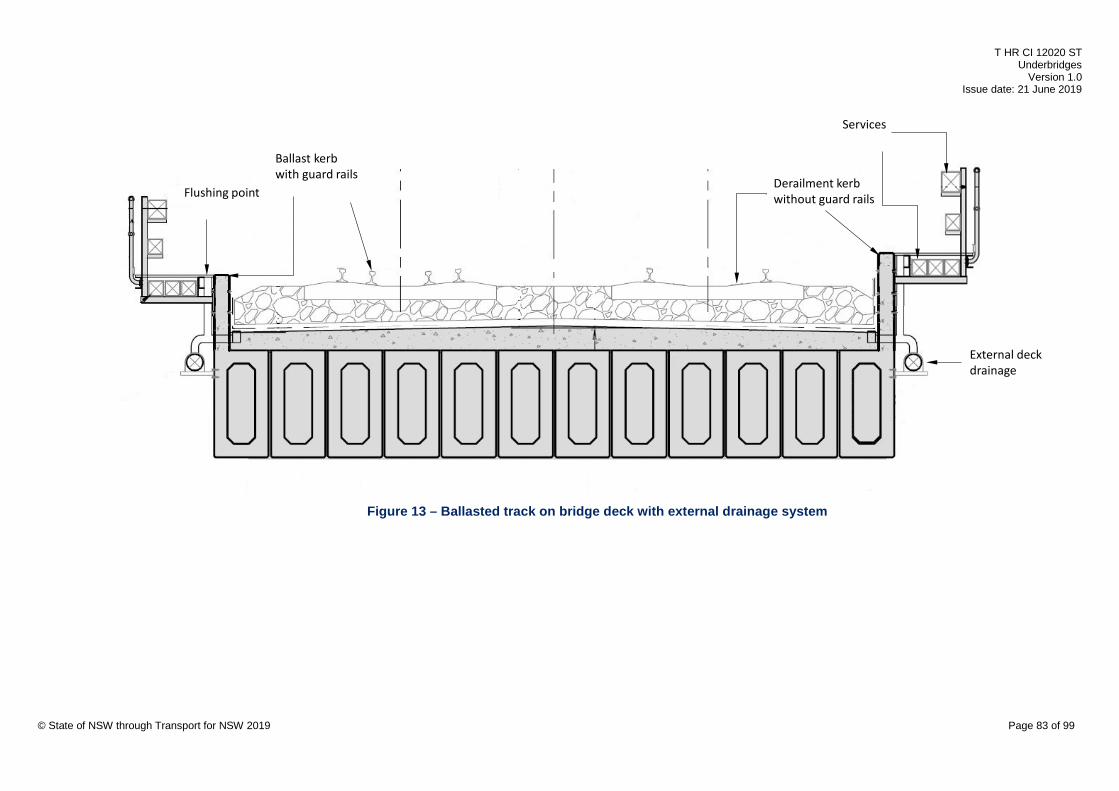
T HR CI 12020 ST Underbridges
Version 1.0 Issue date: 21 June 2019
External deck drainage
Services
Flushing point
Ballast kerb with guard rails
Derailment kerbwithout guard rails
© State of NSW through Transport for NSW 2019 Page 83 of 99
Figure 13 – Ballasted track on bridge deck with external drainage system

T HR CI 12020 ST Underbridges
Version 1.0 Issue date: 21 June 2019
Ballast kerb
Derailment kerbwithout guard rails
Temporary jack location for bearing replacement
Girder designed for collision load
Girder designed for collision load
© State of NSW through Transport for NSW 2019 Page 84 of 99
Figure 14 – Ballasted track on concrete through girder with alternative ballast kerb and derailment kerb
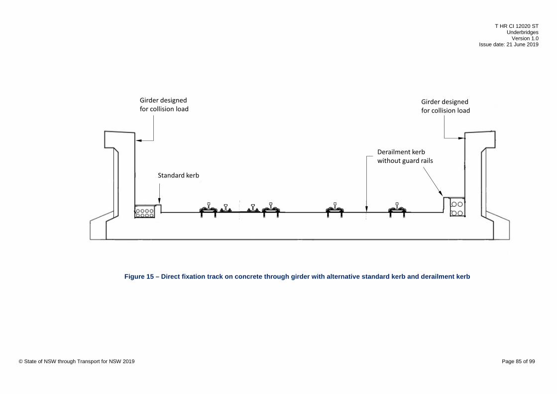
T HR CI 12020 ST Underbridges
Version 1.0 Issue date: 21 June 2019
Girder designed for collision load
Girder designed for collision load
Derailment kerbwithout guard rails
Standard kerb
© State of NSW through Transport for NSW 2019 Page 85 of 99
Figure 15 – Direct fixation track on concrete through girder with alternative standard kerb and derailment kerb
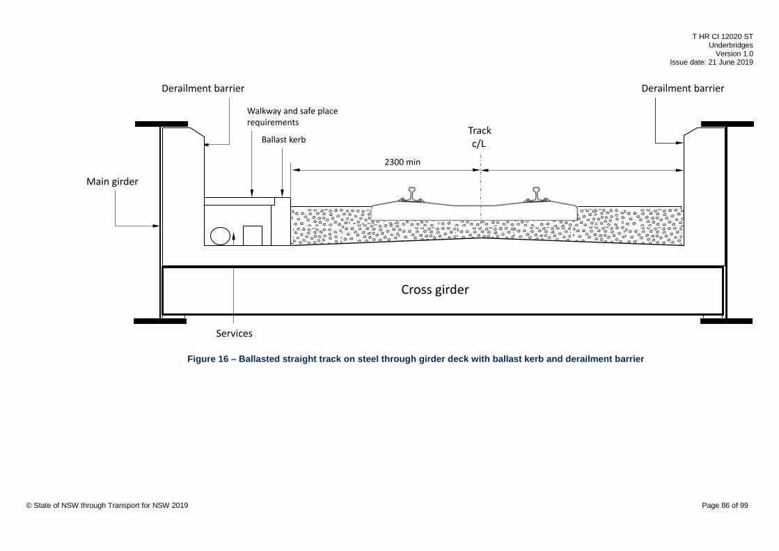
T HR CI 12020 ST Underbridges
Version 1.0 Issue date: 21 June 2019
Ballast kerb
Main girder
Derailment barrier
Walkway and safe place requirements
Services
Derailment barrier
Cross girder
Trackc/L
2300 min
© State of NSW through Transport for NSW 2019 Page 86 of 99
Figure 16 – Ballasted straight track on steel through girder deck with ballast kerb and derailment barrier

T HR CI 12020 ST Underbridges
Version 1.0 Issue date: 21 June 2019
Trackc/L
2300 min 2300 min
Derailment barrier
Walkway and safe place requirements
Derailment barrier
Cross girder
Standard kerb
© State of NSW through Transport for NSW 2019 Page 87 of 99
Figure 17 – Direct fixation straight track on steel through girder deck with ballast kerb and derailment barrier

T HR CI 12020 ST Underbridges
Version 1.0 Issue date: 21 June 2019
© State of NSW through Transport for NSW 2019 Page 88 of 99
Figure 18 – Good practice main girder welding details with fatigue life enhancement

T HR CI 12020 ST Underbridges
Version 1.0 Issue date: 21 June 2019
© State of NSW through Transport for NSW 2019 Page 89 of 99
Figure 19 – Good practice cross girder welding details with fatigue life enhancement
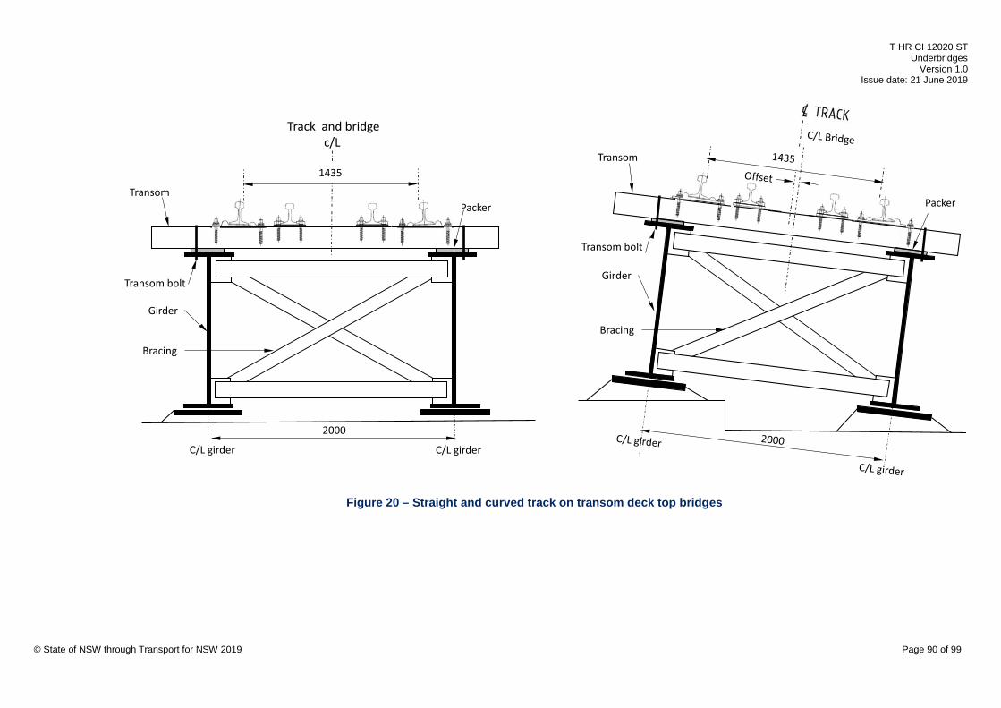
T HR CI 12020 ST Underbridges
Version 1.0 Issue date: 21 June 2019
Track and bridgec/L
Transom bolt
1435
2000
TransomPacker
Girder
C/L girder C/L girder
Bracing
Transom bolt
Transom
Packer
Girder
Bracing
© State of NSW through Transport for NSW 2019 Page 90 of 99
Figure 20 – Straight and curved track on transom deck top bridges

T HR CI 12020 ST Underbridges
Version 1.0 Issue date: 21 June 2019
Capping layer
Approach slab
Dowel bar
Elastomeric strip bearing
Abutment
Engineered backfill
Formation
Cover strip
© State of NSW through Transport for NSW 2019 Page 91 of 99
Figure 21 – Approach slab for ballasted track bridge
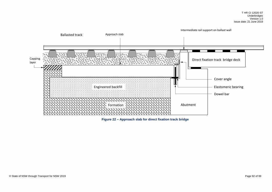
T HR CI 12020 ST Underbridges
Version 1.0 Issue date: 21 June 2019
Capping layer
Intermediate rail support on ballast wallApproach slab
Dowel bar
Elastomeric bearing
Direct fixation track bridge deck
Ballasted track
Abutment
Engineered backfill
Formation
Cover angle
© State of NSW through Transport for NSW 2019 Page 92 of 99
Figure 22 – Approach slab for direct fixation track bridge

T HR CI 12020 ST Underbridges
Version 1.0 Issue date: 21 June 2019
Direct fixation on approach slab with squared end
Direct fixation bridge deckSkewed end approach slab
Ballasted track part of approach slab
Intermediate rail support on end wall (special)
© State of NSW through Transport for NSW 2019 Page 93 of 99
Figure 23 – Plan view of approach slab for skewed end direct fixation track bridge

T HR CI 12020 ST Underbridges
Version 1.0 Issue date: 21 June 2019
Capping layer
Intermediate rail support on ballast wallApproach slab
Dowel bar
Elastomeric bearing
Direct fixation track bridge deck
Abutment
Engineered backfill
Formation
Direct fixation track extended onto approach slab to remove skewed bridge end
© State of NSW through Transport for NSW 2019 Page 94 of 99
Figure 24 – Elevation view of approach slab for skewed end direct fixation track bridge

T HR CI 12020 ST Underbridges
Version 1.0 Issue date: 21 June 2019
Capping layer Approach slab
Stainless steel dowel bar
Elastomeric bearing
Direct fixation track
Abutment without ballast wall
Format
Cover strip
Sub-surface drain Compressible layer length 1000 mm min Bedding layer
© State of NSW through Transport for NSW 2019 Page 95 of 99
Figure 25 – Sloping approach slab for direct fixation track bridge

T HR CI 12020 ST Underbridges
Version 1.0 Issue date: 21 June 2019
Approach slab
Intermediate rail support on ballast wall Sect. 23.3
Direct fixed bridge deck
Abutment
DELKOR combined ALT 1 guard rail plate
Standard concrete sleepers
6 x standard sleepers with SA47 rail pads replacing HDPE pads
10 x special sleepers in accordance with drawings CV 0168625 & CV 0168267
C/L
wal
lBa
llast
© State of NSW through Transport for NSW 2019 Page 96 of 99
Figure 26 – Model ballasted track transition for direct fixation track bridge

T HR CI 12020 ST Underbridges
Version 1.0 Issue date: 21 June 2019
© State of NSW through Transport for NSW 2019 Page 97 of 99
Figure 27 – ‘Goecell’ bridge end embankment on approach to existing direct fixed bridge

T HR CI 12020 ST Underbridges
Version 1.0 Issue date: 21 June 2019
© State of NSW through Transport for NSW 2019 Page 98 of 99
Figure 28 – Embankment earthworks for existing bridge end

T HR CI 12020 ST Underbridges
Version 1.0 Issue date: 21 June 2019
© State of NSW through Transport for NSW 2019 Page 99 of 99
Figure 29 – Ballast retention wall for ends of existing bridges