t rec g.872 201210 i en vigor ingles
DESCRIPTION
g.872TRANSCRIPT

I n t e r n a t i o n a l T e l e c o m m u n i c a t i o n U n i o n
ITU-T G.872TELECOMMUNICATION STANDARDIZATION SECTOR OF ITU
(10/2012)
SERIES G: TRANSMISSION SYSTEMS AND MEDIA, DIGITAL SYSTEMS AND NETWORKS
Digital networks – Optical transport networks
Architecture of optical transport networks
Recommendation ITU-T G.872

ITU-T G-SERIES RECOMMENDATIONS
TRANSMISSION SYSTEMS AND MEDIA, DIGITAL SYSTEMS AND NETWORKS
INTERNATIONAL TELEPHONE CONNECTIONS AND CIRCUITS G.100–G.199 GENERAL CHARACTERISTICS COMMON TO ALL ANALOGUE CARRIER-TRANSMISSION SYSTEMS
G.200–G.299
INDIVIDUAL CHARACTERISTICS OF INTERNATIONAL CARRIER TELEPHONE SYSTEMS ON METALLIC LINES
G.300–G.399
GENERAL CHARACTERISTICS OF INTERNATIONAL CARRIER TELEPHONE SYSTEMS ON RADIO-RELAY OR SATELLITE LINKS AND INTERCONNECTION WITH METALLIC LINES
G.400–G.449
COORDINATION OF RADIOTELEPHONY AND LINE TELEPHONY G.450–G.499 TRANSMISSION MEDIA AND OPTICAL SYSTEMS CHARACTERISTICS G.600–G.699 DIGITAL TERMINAL EQUIPMENTS G.700–G.799 DIGITAL NETWORKS G.800–G.899
General aspects G.800–G.809 Design objectives for digital networks G.810–G.819 Quality and availability targets G.820–G.829 Network capabilities and functions G.830–G.839 SDH network characteristics G.840–G.849 Management of transport network G.850–G.859 SDH radio and satellite systems integration G.860–G.869 Optical transport networks G.870–G.879
DIGITAL SECTIONS AND DIGITAL LINE SYSTEM G.900–G.999 MULTIMEDIA QUALITY OF SERVICE AND PERFORMANCE – GENERIC AND USER-RELATED ASPECTS
G.1000–G.1999
TRANSMISSION MEDIA CHARACTERISTICS G.6000–G.6999 DATA OVER TRANSPORT – GENERIC ASPECTS G.7000–G.7999 PACKET OVER TRANSPORT ASPECTS G.8000–G.8999 ACCESS NETWORKS G.9000–G.9999
For further details, please refer to the list of ITU-T Recommendations.

Rec. ITU-T G.872 (10/2012) i
Recommendation ITU-T G.872
Architecture of optical transport networks
Summary
Recommendation ITU-T G.872 describes the functional architecture of optical transport networks using the modelling methodology described in Recommendations ITU-T G.800 and ITU-T G.805. The optical transport network (OTN) functionality is described from a network level viewpoint, taking into account an optical network layered structure, client characteristic information, client/server layer associations, networking topology, and layer network functionality providing optical signal transmission, multiplexing, routing, supervision, performance assessment and network survivability. The optical portion of the network is described in terms of spectrum management entities and maintenance entities.
History
Edition Recommendation Approval Study Group
1.0 ITU-T G.872 1999-02-26 13
2.0 ITU-T G.872 2001-11-29 15
2.1 ITU-T G.872 (2001) Amd. 1 2003-12-14 15
2.2 ITU-T G.872 (2001) Cor. 1 2005-01-13 15
2.3 ITU-T G.872 (2001) Amd. 2 2010-07-29 15
3.0 ITU-T G.872 2012-10-29 15

ii Rec. ITU-T G.872 (10/2012)
FOREWORD
The International Telecommunication Union (ITU) is the United Nations specialized agency in the field of telecommunications, information and communication technologies (ICTs). The ITU Telecommunication Standardization Sector (ITU-T) is a permanent organ of ITU. ITU-T is responsible for studying technical, operating and tariff questions and issuing Recommendations on them with a view to standardizing telecommunications on a worldwide basis.
The World Telecommunication Standardization Assembly (WTSA), which meets every four years, establishes the topics for study by the ITU-T study groups which, in turn, produce Recommendations on these topics.
The approval of ITU-T Recommendations is covered by the procedure laid down in WTSA Resolution 1.
In some areas of information technology which fall within ITU-T's purview, the necessary standards are prepared on a collaborative basis with ISO and IEC.
NOTE
In this Recommendation, the expression "Administration" is used for conciseness to indicate both a telecommunication administration and a recognized operating agency.
Compliance with this Recommendation is voluntary. However, the Recommendation may contain certain mandatory provisions (to ensure, e.g., interoperability or applicability) and compliance with the Recommendation is achieved when all of these mandatory provisions are met. The words "shall" or some other obligatory language such as "must" and the negative equivalents are used to express requirements. The use of such words does not suggest that compliance with the Recommendation is required of any party.
INTELLECTUAL PROPERTY RIGHTS
ITU draws attention to the possibility that the practice or implementation of this Recommendation may involve the use of a claimed Intellectual Property Right. ITU takes no position concerning the evidence, validity or applicability of claimed Intellectual Property Rights, whether asserted by ITU members or others outside of the Recommendation development process.
As of the date of approval of this Recommendation, ITU had received notice of intellectual property, protected by patents, which may be required to implement this Recommendation. However, implementers are cautioned that this may not represent the latest information and are therefore strongly urged to consult the TSB patent database at http://www.itu.int/ITU-T/ipr/.
ITU 2013
All rights reserved. No part of this publication may be reproduced, by any means whatsoever, without the prior written permission of ITU.

Rec. ITU-T G.872 (10/2012) iii
Table of Contents
Page
1 Scope ............................................................................................................................ 1
2 References..................................................................................................................... 1
3 Terms and definitions ................................................................................................... 2
3.1 Terms defined elsewhere ................................................................................ 2
3.2 Terms defined in this Recommendation ......................................................... 3
4 Abbreviations and acronyms ........................................................................................ 3
5 Conventions .................................................................................................................. 5
6 Functional architecture of optical transport networks .................................................. 6
7 OTN digital layers ........................................................................................................ 7
7.1 Optical channel data unit (ODU) layer network ............................................. 10
7.2 Optical channel transport unit (OTU) layer network ..................................... 14
7.3 Client/server associations ............................................................................... 15
8 OTN optical entities ...................................................................................................... 17
8.1 Optical channel (OCh) layer network ............................................................. 19
8.2 Optical multiplex section (OMS) ................................................................... 22
8.3 Optical transmission section (OTS) ................................................................ 23
8.4 Media entities ................................................................................................. 25
8.5 Client/server associations ............................................................................... 27
9 OTN topology ............................................................................................................... 29
9.1 Unidirectional and bidirectional connections ................................................. 29
9.2 Point-to-multipoint media channels ............................................................... 29
10 OTN management ......................................................................................................... 30
10.1 Generic requirements ...................................................................................... 30
10.2 OTN network management requirements ...................................................... 31
10.3 Connection supervision techniques ................................................................ 34
10.4 Connection supervision applications .............................................................. 34
11 OTN survivability techniques ....................................................................................... 35
11.1 Protection techniques ...................................................................................... 35
11.2 Network restoration ........................................................................................ 35
12 Subdividing of the OTN ............................................................................................... 35
12.1 Domains using the black link approach .......................................................... 36
Appendix I – Examples of multi-domain OTN applications ................................................... 37
Appendix II – Construction of optical channel connections .................................................... 39
Appendix III – An example of the use of the black link approach .......................................... 40
Appendix IV – Relationship between Recommendations ITU-T G.872 and ITU-T G.798 .... 42


Rec. ITU-T G.872 (10/2012) 1
Recommendation ITU-T G.872
Architecture of optical transport networks
1 Scope
This Recommendation describes the functional architecture of optical transport networks using the modelling methodology described in [ITU-T G.800] and [ITU-T G.805]. The optical transport network (OTN) functionality is described from a network level viewpoint, taking into account an optical network layered structure, client characteristic information, client/server layer associations, networking topology, and layer network functionality providing optical signal transmission, multiplexing, routing, supervision, performance assessment and network survivability. The optical portion of the network is described in terms of spectrum management entities and maintenance entities.
This Recommendation is restricted to the functional description of optical transport networks that support digital signals. The support of analogue or mixed digital/analogue signals is outside the scope of this Recommendation.
It is recognized that the design of optical networks is subject to limitations imposed by the accumulation of degradations introduced by the number of network elements and their network topology. However, many of these degradations and the magnitude of their effects are associated with particular technological implementations of the architecture described in this Recommendation and are therefore subject to change as technology progresses. As such, the description of these effects is outside the scope of this Recommendation.
2 References
The following ITU-T Recommendations and other references contain provisions which, through reference in this text, constitute provisions of this Recommendation. At the time of publication, the editions indicated were valid. All Recommendations and other references are subject to revision; users of this Recommendation are therefore encouraged to investigate the possibility of applying the most recent edition of the Recommendations and other references listed below. A list of the currently valid ITU-T Recommendations is regularly published. The reference to a document within this Recommendation does not give it, as a stand-alone document, the status of a Recommendation.
[ITU-T G.694.1] Recommendation ITU-T G694.1 (2012), Spectral grids for WDM applications: DWDM frequency grid.
[ITU-T G.698.1] Recommendation ITU-T G.698.1 (2009), Multichannel DWDM applications with single-channel optical interfaces.
[ITU-T G.698.2] Recommendation ITU-T G.698.2 (2009), Amplified multichannel dense wavelength division multiplexing applications with single channel optical interfaces.
[ITU-T G.707] Recommendation ITU-T G.707/Y.1322 (2007), Network node interface for the synchronous digital hierarchy (SDH).
[ITU-T G.709] Recommendation ITU-T G.709/Y.1331 (2012), Interfaces for the optical transport network (OTN).
[ITU-T G.798] Recommendation ITU-T G.798 (2010), Characteristics of optical transport network hierarchy equipment functional blocks.
[ITU-T G.800] Recommendation ITU-T G.800 (2012), Unified functional architecture of transport networks.

2 Rec. ITU-T G.872 (10/2012)
[ITU-T G.805] Recommendation ITU-T G.805 (2000), Generic functional architecture of transport networks.
[ITU-T G.870] Recommendation ITU-T G.870/Y.1352 (2012), Terms and definitions for optical transport networks (OTN).
[ITU-T G.873.1] Recommendation ITU-T G.873.1 (2011), Optical Transport Network (OTN): Linear protection.
[ITU-T G.873.2] Recommendation ITU-T G.873.2 (2012), ODUk shared ring protection.
[ITU-T G.7712] Recommendation ITU-T G.7712/Y.1703 (2010), Architecture and specification of data communication network.
[ITU-T G.8080] Recommendation ITU-T G.8080/Y.1304 (2012), Architecture for the automatically switched optical network.
3 Terms and definitions
3.1 Terms defined elsewhere
This Recommendation uses the following terms defined elsewhere:
3.1.1 adaptation management [ITU-T G.870]: The set of processes for managing client layer network adaptation to/from the server layer network.
3.1.2 administrative domain [ITU-T G.805]: For the purposes of this Recommendation an administrative domain represents the extent of resources which belong to a single player such as a network operator, a service provider or an end-user. Administrative domains of different players do not overlap amongst themselves.
3.1.3 central frequency [ITU-T G.870]: The nominal1 mid-point of the optical frequency range over which the digital information of a particular OCh-P is modulated.
3.1.4 connection supervision [ITU-T G.805]: The process of monitoring the integrity of a "connection" or "tandem connection" which is part of a "trail".
3.1.5 connectivity supervision [ITU-T G.870]: The set of processes for monitoring the integrity of the routing of the connection between source and sink trail terminations.
3.1.6 continuity supervision [ITU-T G.870]: The set of processes for monitoring the integrity of the continuity of a trail.
3.1.7 effective frequency slot [ITU-T G.870]: The effective frequency slot of a media channel is that part of the frequency slots of the filters along the media channel that is common to all of the filters' frequency slots. It is described by its nominal central frequency and its slot width.
3.1.8 frequency slot [ITU-T G.694.1]: The frequency range allocated to a slot and unavailable to other slots within a flexible grid. A frequency slot is defined by its nominal central frequency and its slot width.
Within this Recommendation a fixed grid device is described in terms of the frequency slots it would have associated with it, if it were a flexible grid device.
3.1.9 inter-domain interface (IrDI) [ITU-T G.870]: A physical interface that represents the boundary between the administrative domains of different network operators. The characteristics are defined in [ITU-T G.709].
____________________ 1 Nominal means the intended mid-point of the range. The actual mid-point may be slightly offset by
impairments such as long term drift.

Rec. ITU-T G.872 (10/2012) 3
3.1.10 intra-domain interface (IaDI) [ITU-T G.870]: A physical interface within the domain of a single network operator. The characteristics are defined in [ITU-T G.709].
3.1.11 maintenance indication [ITU-T G.870]: The set of processes for indicating defects in a connection which is part of a trail in downstream and upstream directions.
3.1.12 management communications [ITU-T G.870]: The set of processes providing communications for management purposes.
3.1.13 media element [ITU-T G.870]: A media element directs the optical signal or affects the properties of an optical signal, it does not modify the properties of the information that has been modulated to produce the optical signal.
3.1.14 network media channel [ITU-T G.870]: A media channel that supports a single OCh-P network connection.
3.1.15 optical channel data unit (ODUk) [ITU-T G.870]: The ODUk is an information structure consisting of the information payload (OPUk) and ODUk-related overhead. See [ITU-T G.709] for the current valid values of k.
3.1.16 optical channel payload unit (OPUk) [ITU-T G.870]: The OPUk is the information structure used to adapt client information for transport over an optical channel. It comprises client information together with any overhead needed to perform rate adaptation between the client signal rate and the OPUk payload rate, and other OPUk overheads supporting the client signal transport. See [ITU-T G.709] for the current valid values of k.
3.1.17 optical channel transport unit (OTUk[V]) [ITU-T G.870]: The OTUk is the information structure used for transport of an ODUk over an OCh trail. See [ITU-T G.709] for the current valid values of k.
3.1.18 optical supervisory channel (OSC) [ITU-T G.870]: The OSC supports the transfer of the non-associated overhead information for the OCh trail, OMS_ME and the OTS_ME.
3.1.19 optical transport hierarchy (OTH) [ITU-T G.870]: The OTH is a hierarchical set of digital transport layers, standardized for the transport of suitably adapted payloads within the OTN.
3.1.20 optical transport network (OTN) [ITU-T G.870]: An optical transport network (OTN) is composed of a set of optical network elements connected by optical fibre links, able to provide functionality of transport, multiplexing, routing, management, supervision and survivability of optical channels carrying client signals, according to the requirements given in [ITU-T G.872].
3.1.21 signal quality supervision See [ITU-T G.870]: The set of processes for monitoring the performance of a connection that is supporting a trail.
3.1.22 slot width [ITU-T G.694.1]: The full width of a frequency slot in a flexible grid.
3.2 Terms defined in this Recommendation
This Recommendation defines the following term:
3.2.1 media channel: A media association that represents both the topology (i.e., the path through the media) and the resource (frequency slot) that it occupies.
4 Abbreviations and acronyms
This Recommendation uses the following abbreviations and acronyms:
AIS Alarm Indication Signal
AP Access Point
APS Automatic Protection Switching

4 Rec. ITU-T G.872 (10/2012)
BDI Backward Defect Indication
BEI Backward Error Indication
CP Connection Point
FDI Forward Defect Indication
FEC Forward Error Correction
IaDI Intra-Domain Interface
IrDI Inter-Domain Interface
LC Link Connection
LOC Loss of Continuity
ME Maintenance Entity
MI Management Information
MSI Multiplex Structure Identifier
NC Network Connection
NE Network Element
NIM Non-Intrusive Monitor
OAM Operation, Administration and Maintenance
OCh Optical Channel
OCh_ME OCh Maintenance Entity
OCh-O OCh – Overhead
OCh-P OCh – Payload
OCI Open Connection Indication
ODU Optical channel Data Unit
OMS Optical Multiplex Section
OMS_ME Optical Multiplex Section Maintenance Entity
OMS-O Optical Multiplex Section – Overhead
OMS-P Optical Multiplex Section – Payload
OSC Optical Supervisory Channel
OTH Optical Transport Hierarchy
OTM Optical Transport Module
OTN Optical Transport Network
OTS Optical Transmission Section
OTS_ME Optical Transmission Section Maintenance Entity
OTSn Optical Transmission Section of order n
OTU Optical Transport Unit
OTUGn Optical Transport Unit Group of order n
SDH Synchronous Digital Hierarchy
SI Status Information (derived by the monitoring of a signal)

Rec. ITU-T G.872 (10/2012) 5
SN Subnetwork
SNC Subnetwork Connection
SRP Shared Ring Protection
STM-N Synchronous Transport Module level N
TCM Tandem Connection Monitoring
TCP Termination Connection Point
TDM Time Division Multiplexing
TS Tributary Slot
TT Trail Termination
TTI Trail Trace Identifier
(D)WDM (Dense) Wavelength Division Multiplexing
5 Conventions
This Recommendation uses the diagrammatic conventions defined in [ITU-T G.800] and [ITU-T G.805] with the additional diagrammatic and terminological conventions described in this clause, to distinguish between the topological components and transport processing functions described in [ITU-T G.800] that act on digital signals and media functions described in this Recommendation.
Media elements act on the signals that they convey and have some similarity to the topological components and transport processing functions described in [ITU-T G.800]. However, media elements only direct or affect the physical signal but do not process the information carried in the characteristic information. Given the similarity between these functions, it is convenient to reuse the symbol shapes defined in [ITU-T G.800] with the addition of shading to distinguish between media elements and transport processing functions. These symbols are shown below in Figure 5-1. This Recommendation builds on the familiarity with transport functions while preserving important distinctions by means of its graphical conventions.
A shaded non-intrusive monitor (NIM) only monitors the optical properties of a signal.
G.872(12)_F5-1
Digital layers
Media layer
Non-intrusive monitor
Figure 5-1 – Element shading convention
The following terminological conventions are used to distinguish between signal associations and media associations.
Connection: Is used to denote a signal association as defined in [ITU-T G.800] and [ITU-T G.805].
Media channel: Is used to denote a media association.

6 Rec. ITU-T G.872 (10/2012)
6 Functional architecture of optical transport networks
The functionality of optical transport networks comprises of providing transport, aggregation, routing, supervision and survivability of client signals that are processed in both the photonic and digital domains. This functionality for optical transport networks is described from a network level viewpoint using the generic principles defined in [ITU-T G.800] and [ITU-T G.805]. The specific aspects concerning the OTN layered structure, characteristic information, client/server layer associations, network topology and layer network functionality are provided in this Recommendation.
In accordance with [ITU-T G.805] and [ITU-T G.800], the OTN is decomposed into independent transport layer networks where each layer network can be separately partitioned in a way which reflects the internal structure of that layer network.
In the following functional description, optical signals are characterized by central frequency and the maximum spectral excursion2 (see [ITU-T G.698.2]). The optical signal is guided to its destination by a network media channel. The nominal central frequency and width of a media channel are defined by its frequency slot. A frequency slot is defined in [ITU-T G.694.1], and within this Recommendation a fixed grid device is described in terms of the frequency slots it would have associated with it if it were a flexible grid device.
G.872(12)_F6-1
ODU
OTU
OChOT
N
Spectrum configurationentities
Signal managemententities
FibreMedia
Digital layers
OT
H
OCh layer
Figure 6-1 – Overview of the OTN
Above the OCh layer are the digital layers (OTU, ODU) that provide for the multiplexing of digital clients and for their maintenance. The OCh termination emits two signals: the OCh-P signal, which is carried in a media channel over media elements (the optical signal is not demodulated by any of the media elements) and the OCh-O signal, which carries OCh overhead information.
The digital layers are described in clause 7 and the OCh layer and media are described in clause 8.
Following the conventions of clause 5, the term "connection" is used to denote a signal association, while the term "media channel" is used to denote a media association. A network media channel is the media association that supports a single OCh-P network connection.
Below the OCh, the entities that provide for configuration of the media channels are described separately from the entities that provide management of the collections of the OCh-P signals that traverse the media3.
____________________ 2 The OCh-P spectrum after the modulation process is out of the scope of this Recommendation. 3 This separation is necessary to allow the description of media elements that may act on more than a single
OCh-P signal. The relationship between the model provided in this Recommendation and the existing functions and processes described in [ITU-T G.798] is provided in Appendix IV.

Rec. ITU-T G.872 (10/2012) 7
The effective frequency slot of a media channel is defined by the filters that are in the path of the media channel. The effective frequency slot may be sufficient to support more than one OCh-P signal4. The media channel is switched by media matrices (analogue media elements).
The OCh-P signals carried by the media channel are monitored by the OMS and OTS maintenance entities (MEs) (described in clauses 8.2 and 8.3 respectively), which are responsible for non-intrusively inspecting the bulk properties of the OCh-P signals. This inspection results in management information (MI) that is passed to a management system, as well as to the far end of the maintenance entity.
7 OTN digital layers
The digital OTN layered structure is comprised of digital path layer networks (ODU) and digital section layer networks (OTU).
An OTU section layer supports one ODU path layer network as the client, and provides a monitoring capability for the OCh. An ODU path layer may transport a heterogeneous assembly of ODU clients. The heterogeneous multiplexing hierarchy supports various network architectures, including those optimized to minimize stranded capacity, minimize managed entities, support carrier's carrier scenarios, and/or enable ODU0/ODUflex traffic to transit a region of the network that does not support these capabilities.
Figures 7-1 and 7-2 show the client/server relationships without ODU multiplexing and with ODU multiplexing, respectively.
____________________ 4 A media channel that may carry multiple OCh-P signals may be used to provide what is commonly called
a "waveband" or "express" channel.

8 Rec. ITU-T G.872 (10/2012)
G.872(12)_F7-1
OTU AP OTU AP
OTU TCPOTU_NC
OTU trail
ODU/Client_ASink
ODU APODU trail
ODU AP
ODU layernetwork
ODU TCP
OTU/ODU_ASource
OTU/ODU_ASink
OTU layernetwork
ODU_TTSource
ODU_TTSink
OTU_TTSource
OTU_TTSink
OTU TCP
ODU/Client_ASource
ODU TCPODU_NC
Figure 7-1 – Client/server association of the digital OTN layers without ODU multiplexing

Rec. ITU-T G.872 (10/2012) 9
G.872(12)_F7-2
ODUk AP
OTUk AP
ODUk TCP
OTUk TCP
ODUk AP
OTUk AP
ODUk_NC
OTUk_NC
ODUk trail
OTUk trail
ODUk trail
ODUj/Client_ASink
ODUj APODUj trail
ODUj AP
ODUj layernetwork
ODUj TCP
ODUk TCP
OTUk TCP
ODUk/ODUj_ASource
OTUk/ODUk_ASource
ODUk/ODUj_ASink
OTUk/ODUk_ASink
ODUk layernetwork
OTUk layernetwork
ODUj_TTSource
ODUj_TTSink
ODUk_TTSource
OTUk_TTSource
ODUk_TTSink
OTUk_TTSink
ODUj/Client_ASource
ODUj TCPODUj_NC
k > j
Figure 7-2 – Client/server association of the digital OTN layers with ODU multiplexing
The set of ODU clients and their ODU servers and the set of client ODUs and the server OTU signals, at the time of publication of this Recommendation, are provided in Tables 7-1 and 7-2 respectively. The set of ODU and OTU signals is provided by [ITU-T G.709].

10 Rec. ITU-T G.872 (10/2012)
Table 7-1 – Set of ODU clients and their ODU servers
ODU Clients ODU Server
1.25 Gbit/s bit rate area ODU0
–
2.5 Gbit/s bit rate area ODU1
ODU0
10 Gbit/s bit rate area ODU2
ODU0, ODU1, ODUflex
10.3125 Gbit/s bit rate area ODU2e
–
40 Gbit/s bit rate area ODU3
ODU0, ODU1, ODU2, ODU2e, ODUflex
100 Gbit/s bit rate area ODU4
ODU0, ODU1, ODU2, ODU2e, ODU3, ODUflex,
CBR clients from greater than 2.5 Gbit/s to 100 Gbit/s, or GFP-F mapped packet clients from 1.25 Gbit/s to 100 Gbit/s. ODUflex
–
Table 7-2 – ODU clients and their OTU server
ODU client OTU server
ODU0 –
ODU1 OTU1
ODU2 OTU2
ODU2e –
ODU3 OTU3
ODU4 OTU4
ODUflex –
7.1 Optical channel data unit (ODU) layer network
This layer network provides the functionality for end-to-end networking of digital path signals for transparently conveying client information of varying formats as described in Table 7-1. The description of supported client layer networks is outside the scope of this Recommendation. The topological components of the ODU layer network are subnetworks and links. The links are supported by an OTU trail or a server ODU trail. Since the resources that support these topological components support a heterogeneous assembly of ODUs, the ODU layer is modelled as a single layer network that is independent of bit rate. The ODU bit rate is a parameter that allows the number of tributary slots (TS) for the ODU link connection to be determined. To provide end-to-end networking, the following capabilities are included in the layer network:
– ODU connection rearrangement for flexible network routing;
– ODU overhead processes for ensuring the integrity of the ODU adapted information;
Rec. ITU-T G.872 (10/2012) 11
– ODU operations, administration and maintenance functions for enabling network level operations and management functions, such as connection provisioning, quality of service parameter exchange and network survivability.
The ODU layer network provides for the end-to-end transport of digital client signals through the OTN. The characteristic information of an ODU layer network is composed of:
– the ODU payload area for the transport of the digital client signals
– the ODU overhead area for the transport of the associated overhead.
Details are described in [ITU-T G.709].
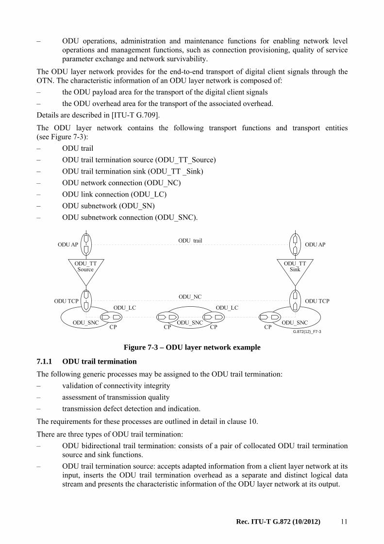
The ODU layer network contains the following transport functions and transport entities (see Figure 7-3):
– ODU trail
– ODU trail termination source (ODU_TT_Source)
– ODU trail termination sink (ODU_TT _Sink)
– ODU network connection (ODU_NC)
– ODU link connection (ODU_LC)
– ODU subnetwork (ODU_SN)
– ODU subnetwork connection (ODU_SNC).
G.872(12)_F7-3
ODU_SNCCPCP
ODU AP
ODU_TTSource
ODU TCP
ODU AP
ODU TCP
ODU_TTSink
ODU trail
ODU_NC
ODU_SNC ODU_SNCCP CP
ODU_LC ODU_LC
Figure 7-3 – ODU layer network example
7.1.1 ODU trail termination
The following generic processes may be assigned to the ODU trail termination:
– validation of connectivity integrity
– assessment of transmission quality
– transmission defect detection and indication.
The requirements for these processes are outlined in detail in clause 10.
There are three types of ODU trail termination:
– ODU bidirectional trail termination: consists of a pair of collocated ODU trail termination source and sink functions.
– ODU trail termination source: accepts adapted information from a client layer network at its input, inserts the ODU trail termination overhead as a separate and distinct logical data stream and presents the characteristic information of the ODU layer network at its output.

12 Rec. ITU-T G.872 (10/2012)
– ODU trail termination sink: accepts the characteristic information of the ODU layer network at its input, extracts the separate and distinct logical data stream containing the ODU trail termination overhead and presents the adapted information at its output.
7.1.2 ODU connection function
The ODU connection function may be used by the network operator to provide routing, grooming, protection and restoration.
NOTE – The ODU connection function may support ODUks with all values of k or only a subset.
7.1.3 ODU transport entities
Network connections, subnetwork connections, matrix connections, link connections, tandem connections and trails are as described in [ITU-T G.805].
7.1.4 ODU topological components
Layer networks, subnetworks, matrices, links, transitional links and access groups are as described in [ITU-T G.805] and [ITU-T G.800].
The ODU subnetwork, ODU_SN, provides flexibility within the ODU layer. Characteristic information is routed between input (termination) connection points [(T)CPs] and output (T)CPs.
NOTE – The ODU topological components may support ODUks with all values of k or only a subset.
7.1.5 ODU time division multiplexing
In order to allow the transport of several lower bit rate ODUj signals over a higher bit rate ODUk signal, while maintaining the end-to-end trail for these lower bit rate signals, time division multiplexing (TDM) of ODUs is defined.
Note that the ODUj may be an ODUflex. The tributary slots of the ODUk server may be allocated to any combination of ODUj clients up to the capacity of the ODUk. For the currently defined ODUks the tributary slots according to Table 7-3 are defined.
Table 7-3 – Number of tributary slots (TS) for each ODUk
Nominal TS capacity
1.25 Gbit/s 2.5 Gbit/s
ODU1 2 –
ODU2 8 4
ODU3 32 16
ODU4 80 –
7.1.6 Multi-domain OTN
Domain A may have an OTN network comprised of client ODUi and server ODUj, i < j. The server ODUj may be carried over the network of domain B, interconnected by OTUj. Domain B may carry the ODUj as a client ODU over a server ODUk, j < k. Each of domains A and B sees two hierarchical ODU levels within their respective domains. The ODUj plays the role of a server ODU in domain A and the role of a client ODU in domain B.
A server ODUj of domain A can also be carried as a client ODUj in domain B directly over OTUj in domain B using TCM to manage the segments of the ODUj path in each domain.
Some examples of multi-domain applications are given in Appendix I.

Rec. ITU-T G.872 (10/2012) 13
7.1.7 Inverse multiplexing in the OTN
Inverse multiplexing in the OTN is implemented by means of virtual concatenation of X (X ≥ 2) ODU signals (ODU-Xv). The ODU-Xv signal can transport a client signal (e.g., an ODU2-4v may transport an STM-256). The characteristic information of a virtually concatenated ODU (ODU-Xv) layer network is transported via a bundle of X ODU network connections, each having its own transfer delay. The ODU-Xv trail termination sink function has to compensate this differential delay, in order to provide a contiguous payload at its output.
The connection monitoring techniques are applied per data stream on the ODU characteristic information.
In virtually concatenated ODU connections which extend across several networks, care should be taken during path set-up to ensure that the worst-case differential delay (e.g., during a protection switch in one of the intermediate networks) does not exceed the chosen compensation range.
Performance monitoring and protection are carried out on the individual ODU signals which make up the virtually concatenated group. Performance monitoring on the group as an entity is for further study.
NOTE – The transport of higher rate ODU signals via a virtually concatenated group of lower rate ODU signals is possible, but results in a non-optimal solution.
Figure 7-4 shows the functional architecture for an ODU-Xv.
. . . . . .
G.872(12)_F7-4
ODU-X AP
ODU-Xv
ODU-X AP
ODU-Xv
ODU TCP
ODU TCP ODU TCP
ODU CP
ODU_SNC
ODU CP
ODU CP
ODU_SNC
ODU CP
OTU/ODU
OTU/ODU
ODU-Xv SNC= X × ODU_SNC
OTU/ODU
OTU/ODU
OTU/ODU
OTU/ODU
OTU/ODU
OTU/ODU
ODU-X trailODU-X/
ClientODU-X/Client
ODU_NC
ODU_NC
ODU TCP
Figure 7-4 – Functional architecture for virtual concatenation of ODUs
The compound function ODU-Xv indicated in Figure 7-4 is further composed from basic atomic functions as shown in Figure 7-5.

14 Rec. ITU-T G.872 (10/2012)
G.872(12)_F7-5
Client_CP
ODU-X/Client ODU-X/Client
ODU-X
ODU-X_TCP
ODU/ODU-X
1 2 Y X
ODU_AP
ODU
ODU-Xv
OD
U in
vers
e m
ulti
plex
ing
subl
ayer
ODU_TCP
ODU-X_AP
ODU
ODU
ODU
Figure 7-5 – Virtual concatenation model
7.2 Optical channel transport unit (OTU) layer network
The OTU layer network provides for the transport of ODU client signals through an OTU trail between 3R points of the OTN. The capabilities of this layer network include:
– OTU overhead processes for ensuring the integrity of the OTU adapted information and conditioning for its transport over an OCh;
– OTU operations, administration and maintenance functions for enabling section level operations and management functions.
The characteristic information of an OTU layer network is composed of:
– the OTU payload area for the transport of the ODU client signal
– the OTU overhead area for the transport of the associated overhead.
Details are described in [ITU-T G.798].
The OTU layer network contains the following transport functions and transport entities (see Figure 7-6):
– OTU trail
– OTU trail termination source (OTU_TT_Source)
– trail termination sink (OTU_TT_Sink)
– OTU network connection (OTU_NC)
– OTU link connection (OTU_LC).

Rec. ITU-T G.872 (10/2012) 15
G.872(12)_F7-6CPCP
OTU AP
OTU_TTSource
OTU TCP
OTU AP
OTU TCP
OTU_TTSink
OTU trail
OTU_NC
CP
OTU_LC OTU_LC OTU_LC OTU_LC
Figure 7-6 – OTU layer network example
7.2.1 OTU trail termination
The following generic processes may be assigned to the OTU trail termination:
– validation of connectivity integrity
– assessment of transmission quality
– transmission defect detection and indication.
The requirement for these processes is outlined in detail in clause 10.
There are three types of OTU trail termination:
– OTU bidirectional trail termination: consists of a pair of collocated OTU trail termination source and sink functions.
– OTU trail termination source: accepts adapted information from an ODU network at its input, inserts the OTU trail termination overhead as a separate and distinct logical data stream and presents the characteristic information of the OTU layer network at its output.
– OTU trail termination sink: accepts the characteristic information of the OTU layer network at its input, extracts the separate and distinct logical data stream containing the OTU trail termination overhead and presents the adapted information at its output.
7.2.2 OTU transport entities
Network connections, link connections and trails are as described in [ITU-T G.805].
7.2.3 OTU topological components
Layer networks, links and access groups are as described in [ITU-T G.805]. When an OTU is carried by an OCh there is a 1:1 correspondence between the OTU and OCh layer networks and access groups.
7.3 Client/server associations
A principal feature of the OTN is the possibility of supporting a wide variety of circuit and packet client layer networks. See [ITU-T G.709].
The structure of the OTN digital layer networks and the adaptation functions are shown in Figures 7-1 and 7-2. For the purposes of description, the interlayer adaptation is named using the server/client relationship.

16 Rec. ITU-T G.872 (10/2012)
7.3.1 ODU/client adaptation
The ODU/client adaptation (ODU/Client_A) is considered to consist of two types of processes: client-specific processes and server-specific processes. The description of the client-specific processes is outside the scope of this Recommendation.
The bidirectional ODU/client adaptation (ODU/Client_A) function is performed by a collocated pair of source and sink ODU/client adaptation functions.
The ODU/client adaptation source (ODU/Client_A_So) performs the following processes between its input and its output:
– all the processing required to adapt the client signal to the ODU payload area. The processes are dependent upon the particular client signal;
– generation and termination of management/maintenance signals as described in clause 10.
The ODU/client adaptation sink (ODU/Client_A_Sk) performs the following processes between its input and its output:
– recovery of the client signal from the ODU payload area. The processes are dependent upon the particular client/server relationship;
– generation and termination of management/maintenance signals as described in clause 10.
A detailed description is provided in [ITU-T G.798].
7.3.2 ODUk/ODUj adaptation
The bidirectional ODUk/ODUj adaptation (ODUk/ODUj_A) function is performed by a collocated pair of source and sink ODUk/ODUj adaptation functions.
The ODUk/ODUj adaptation source (ODUk/ODUj_A_So) performs the following processes between its input and its output:
– ODUj multiplexing to form a higher bit rate ODUk;
– generation and termination of management/maintenance signals as described in clause 10.
The ODUk/ODUj adaptation sink (ODUk/ODUj_A_Sk) performs the following processes between its input and its output:
– ODUj demultiplexing;
– generation and termination of management/maintenance signals as described in clause 10.
A detailed description is provided in [ITU-T G.798].
7.3.3 OTU/ODU adaptation
The bidirectional OTU/ODU adaptation (OTU/ODU_A) function is performed by a collocated pair of source and sink OTU/ODU adaptation functions.
The OTU/ODU adaptation source (OTU/ODU_A_So) performs the following processes between its input and its output:
– all the processing required to adapt the ODU signal to the OTU payload area. The processes are dependent upon the particular implementation of the client/server relationship.
The OTU/ODU adaptation sink (OTU/ODU_A_Sk) performs the following processes between its input and its output:
– recovery of the ODU signal from the OTU payload area. The processes are dependent upon the particular implementation of the client/server relationship.
A detailed description is provided in [ITU-T G.798].

Rec. ITU-T G.872 (10/2012) 17
8 OTN optical entities
G.872(12)_F8-1
OCh-P/OTU
OCh-P_AI
OCh-P
OCh-P_CI
OCh-P_CI
OCh-P
OCh-P_CI
SI
Coordination
OCh-Pfilter
Spectrummanagement
entities
OMS-P_CI
OMS-PNIM
OCh-O
OCh-O_CI
OCh-O
OCh-O_CI
OMS-O/OCh-O
OMS-O_AI
SI
SI
Signalmanagement
entities
OMS-O
OMS-O_CI
OTS-O/OMS-O
OTS-O_AI
OTS-O
OSC/OTS-O
OSC
OTS-PNIM
OSCfilter
OTS-CI
OCh-PNIM
Figure 8-1 – OTN media layer overview
As noted in clause 6, the entities associated with the OTN media layer are distinguished according to whether they provide management of the collections of OCh-P signals traversing the media or whether they provide for configuration of the media channels. The former handle the management of signals via the non-associated overheads and overhead structure defined in [ITU-T G.709]. The latter provide the configuration of the media elements.
Accordingly, the functions for non-associated overhead processing are identified by the -O suffix, and the set of media elements operating on the OCh-P(called the payload) are identified by the -P suffix. The payload processing functions use the processes defined in [ITU-T G.798] and the frame formats of [ITU-T G.709]. The non-associated overhead processing functions use the processes defined in [ITU-T G.798].
Figure 8-1 above provides an overview of the elements of the media layer of the OTN. The only client of the OCh (the OTU) is presented to the OCh-P/OTU adaptation function. The OCh-P termination function sources (or sinks) the OCh-P, which has a specified central frequency, spectral excursion and other parameters. The OCh-P network connection is supported by a network media

18 Rec. ITU-T G.872 (10/2012)
channel. The optical multiplex section (OMS) and optical transport section (OTS) are described in clauses 8.2 and 8.3 respectively.
The concatenation of all media elements between an OCh-P source and an OCh-P sink is called a network media channel.
The spectrum may be allocated and switched in larger portions than that of a network media channel and therefore may support more than one OCh-P signal.
The OCh layer network provides for the transport of OCh-P that transparently convey OTU information between 3R points of the OTN. In order to do so, the following capabilities are included in the layer network:
– OCh-P signal transport;
– OCh-O overhead processes that monitor the integrity of the OCh AI information; note that these processes may include information obtained directly from the OCh-P termination function (i.e., OCh-P management information);
– OCh (both OCH-P and OCh-O) operations, administration and maintenance functions for enabling network level operations and management functions, such as connection provisioning, quality of service parameter exchange and network survivability;
– OCh-P non-intrusive monitor (OCh-P NIM), monitoring the optical properties of the OCh-P signal.
The OCh-P network connection is supported by a network media channel, which provides for flexible network routing.
G.872(12)_F8-2
Media channelmatrix
Media channelmatrix
OCh-Pfilter
OCh-PfilterOMS-P
NIM
OTS-PNIM
OTS_ME
OTS-PNIM
OMS_ME
Amp
OTS-PNIM
OTS_ME
OSCOSCfilter
OSCfilter
OSC
Fibre Fibre
OSCfilter
OSCfilter
OTS-PNIM
OMS-PNIM
Figure 8-2 – OMS and OTS maintenance entities
Figure 8-2 above shows the location of the OMS and OTS maintenance entities.
The OMS maintenance entity (OMS_ME) monitors all of the OCh-P signals on a fibre between two points of frequency slot flexibility. The OTS maintenance entity (OTS_ME) monitors all of the

Rec. ITU-T G.872 (10/2012) 19
OCh-P signals on a fibre between two points of management visibility. These points are usually associated with intermediate amplifier5 sites.
The optical supervisory channel (OSC) is a signal inserted on the OTS_ME. It is used to carry the non-associated overhead of the OCh_ME, OMS_ME and OTS_ME. An OTN compliant network implementation must support the OSC at its intra-domain interfaces. If the OSC is not supported, then the OMS_ME and OTS_ME are not supported. The OCh-P_NC (see clause 8.1) can exist in the absence of the OMS_ME and OTS_ME, however, some of the alarm management, fault detection and fault isolation capabilities for the OCh trail described in clause 10 will not be supported. The OSC is not supported at the IrDI interface since the media channel between the OCh-P source and sink has no intermediate network elements, the full maintenance capabilities are provided by the OTU layer network.
Optical multiplex section maintenance entity (OMS_ME): This maintenance entity provides:
– bulk monitoring of the OMS-P signal by means of the OMS-P non-intrusive monitor (OMS-P NIM) (see clause 8.2);
– OMS overhead processes for ensuring the integrity of the OMS-P, by means of the OMS-O functions;
– OMS operations, administration and maintenance functions for enabling section level operations and management functions, such as multiplex section survivability.
These networking capabilities performed for multi-wavelength optical signals provide support for the operation and management of optical networks.
Optical transmission section maintenance entity (OTS_ME): This maintenance entity provides:
– bulk monitoring of the OTS-P signal (see clause 8.3) by means of the OTS-P non-intrusive monitor (OTS-P NIM);
– OTS overhead processing for ensuring the integrity of the OTS-P by means of the OTS-O functions;
– OTS operations, administration and maintenance functions for enabling section level operations and management functions.
The media layer network supports network media channels between OCh-P terminations as described in clause 6. A network media channel is constructed from any combination of network elements and fibres as described in clause 8.4.3.
The functional descriptions of the optical layer networks are given in the following clauses. The detailed description of this layer is outside the scope of this Recommendation.
8.1 Optical channel (OCh) layer network
The OCh layer network provides for the transport of digital OTU signals through an OCh trail between access points. The characteristic information of an OCh layer network is composed of two separate and distinct logical signals:
– an optical signal defined by a set of parameters. The central frequency, required bandwidth and other analogue parameters such as signal-to-noise ratio associated with the network media channel are of particular interest. The parameters are captured in an application
____________________ 5 For distributed optical amplifiers, the location of the amplifier is considered to be the location where the
pump wavelength is inserted.
20 Rec. ITU-T G.872 (10/2012)
identifier6, which covers both standardized as well as proprietary applications. Layer processors [ITU-T G.800] in the path may modify these parameters as required.
– A data stream that constitutes non-associated (out-of-band) overhead. This data stream has its own set of functions that process the non-associated overhead independent of the layer processors which affect the OCh-P.
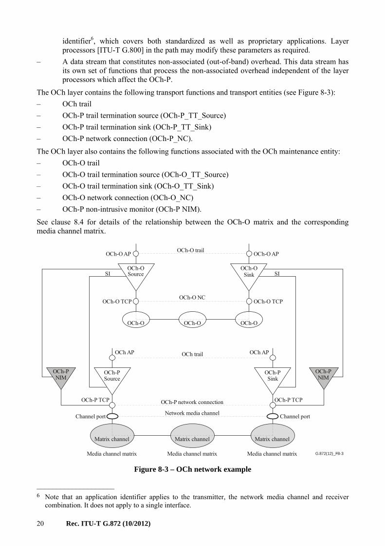
The OCh layer contains the following transport functions and transport entities (see Figure 8-3):
– OCh trail
– OCh-P trail termination source (OCh-P_TT_Source)
– OCh-P trail termination sink (OCh-P_TT_Sink)
– OCh-P network connection (OCh-P_NC).
The OCh layer also contains the following functions associated with the OCh maintenance entity:
– OCh-O trail
– OCh-O trail termination source (OCh-O_TT_Source)
– OCh-O trail termination sink (OCh-O_TT_Sink)
– OCh-O network connection (OCh-O_NC)
– OCh-P non-intrusive monitor (OCh-P NIM).
See clause 8.4 for details of the relationship between the OCh-O matrix and the corresponding media channel matrix.
G.872(12)_F8-3
OCh-OSource
OCh-O AP
OCh-O TCP
OCh-OSink
OCh-PSink
OCh-PSource
OCh-O NC
OCh-O trail
OCh-OOCh-O
Matrix channel Matrix channel Matrix channel
OCh-O
OCh-O AP
OCh AP OCh AP
OCh-O TCP
OCh-P TCP
Channel portChannel port
OCh-P TCP
OCh-PNIM
OCh-PNIM
OCh-P network connection
Network media channel
Media channel matrixMedia channel matrixMedia channel matrix
OCh trail
SISI
Figure 8-3 – OCh network example
____________________ 6 Note that an application identifier applies to the transmitter, the network media channel and receiver
combination. It does not apply to a single interface.

Rec. ITU-T G.872 (10/2012) 21
The signal is emitted or terminated by an OCh-P trail termination. The stream may be modified by a layer processor function, which may be remote from the OCh-P_TT. This allows describing both frequency-specific and frequency-agnostic regions of the OCh layer network.
The central frequency parameter can be used to construct a wavelength-specific routing topology.
The OCh-P characteristic information is formally described as;
CI(oc) = AI+{ <Central Frequency>,<Set of Application Identifiers>}
Note that the client AI determines the client bit rate, and while this may be described by a parameter, that parameter is a part of the client AI and is not an OCh layer parameter.
Table 8-1 – OCh-P CI parameters
Application identifier The application identifier parameter contains the set of application identifiers supported by the function. (Note)
Central frequency The central frequency of the emitted signal. This is the nominal mid-point of the optical frequency range over which the digital information of the particular OCh-P is modulated. The OCh-P spectrum after the modulation process is out of the scope of this Recommendation.
NOTE – An application identifier includes the application codes defined in the appropriate optical system Recommendations, as well as the possibility of proprietary identifiers. The identifier covers all aspects of the signal, including forward error correction, baud rate and modulation type.
8.1.1 OCh trail termination
The following generic processes take place at the OCh trail termination:
– transmission defect detection and indication.
The requirement for these processes is outlined in detail in clause 10.2.
There are three types of OCh trail termination:
– OCh bidirectional trail termination: consists of a pair of collocated OCh trail termination source and sink functions.
– OCh trail termination source: accepts adapted information from the OTU layer network at its input, inserts the OCh trail termination overhead as a separate and distinct logical data stream, modulates AI onto the optical signal and sets its central frequency and presents the characteristic information of the optical channel layer network at its output.
– OCh trail termination sink: accepts the characteristic information of the OCh layer network at its input, demodulates the optical signal7 and presents the adapted information at its output, processes the separate and distinct logical data stream containing the OCh trail termination overhead8.
The processes of the OCh trail termination are supported by the following functions:
– OCh-P_TT, handling the OCh-P signal
– OCh-P NIM, monitoring the optical properties of the OCh-P signal
– OCh-O handling the non-associated overhead of the OCh trail.
____________________ 7 Note that this process may rely on information extracted by the OCh/OTU adaptation function. 8 Note that the optical signal may be demodulated if the OAM data stream is absent, however the OAM
processing described in clause 10 will not be available.

22 Rec. ITU-T G.872 (10/2012)
8.2 Optical multiplex section (OMS)
The characteristic information in an optical multiplex OMS is composed of two separate and distinct logical signals:
– OMS-P signal that consists of a set of n OCh-P signals which, taken as a set, have a defined aggregate optical bandwidth;
– a data stream that constitutes the non-associated OMS overhead (OMS-O). This data stream is processed by OMS-O components. (OMS-O_TT, OMS-O/OCh-O adaptation functions).
The OMS media channel represents the media association between OMS-P end points and is a concatenation of one or more fibres and zero or more amplifiers.
The OMS-P non-intrusive monitor (NIM) monitors the bulk properties of the OMS-P signal at the ingress and egress of the OMS maintenance entity (OMS_ME) and provides information that is carried by the non-associated OMS-O.
The OMS-P signal is assembled by a combination of filter components (see clause 8.4). The filter components and the OMS-P NIM are logically related; however, they may not necessarily be physically co-collocated9 with the OMS-P NIM (which monitors the signal) or the OMS-O (which operates on the overhead). That is, the OMS NIM and the aggregation or disaggregation of the OCh-P signals may take place in different locations. This means that the span of an OMS media channel may be greater than or equal to the span of the OMS_ME, however, the OMS media channel is not monitored over its full span.
The OMS is the association between the end points of the OMS_ME.
An OCh within an OMS may be either allocated (in-service) or may be unallocated (out-of-service). The OCh-P signal of an in-service OCh may be present or not.
The OMS is supported by the following functions (see Figure 8-4):
– OMS-O source (OMS_ME_Source) handling the non-associated overhead of the OMS_ME;
– OMS-O sink (OMS_ME_Sink) handling the non-associated overhead of the OMS_ME;
– OMS-P NIM, monitoring the optical properties of the OMS-P signal.
G.872(12)_F8-4
OCh-Pfilter
OCh-Pfilter
OMS-OSource
OMS-O AP
OMS-O TCP
OMS-OSink
OMS-PNIM
OMS-PNIM
OMS-O_NC
OMS-O trailOMS-O AP
OMS-O TCP
OMS-P media channel
SISI
OMS_ME
Figure 8-4 – OMS example
____________________ 9 Collocated components are on the same network element.

Rec. ITU-T G.872 (10/2012) 23
8.2.1 OMS-O overhead termination
The following generic processes are assigned to the optical multiplex section trail termination:
– assessment of transmission quality;
– transmission defect detection and indication.
The requirement for these processes is outlined in detail in clause 10.210.
There are three types of optical multiplex section trail termination:
– OMS-O bidirectional termination: consists of a pair of collocated optical multiplex section termination source and sink functions;
– OMS-O_TT source: accepts the input from the OMS NIM and generates the OMS overhead. That overhead may be carried by out of band means to an OMS-O_TT sink;
– OMS-O_TT sink: processes the OMS overhead and the input from the OMS NIM and generates any OMS management information.
Note that the bulk property monitoring takes place in the co-collocated OMS-P non-intrusive monitor (NIM in the figures).
8.2.2 OMS-O transport entities
The only entity is the OMS-O trail.
8.3 Optical transmission section (OTS)
The OTS is a single unidirectional fibre between points of management visibility. In general, this is the fibre between two network elements, e.g., between amplifiers or between an amplifier and the point where the OMS-P signal is aggregated or disaggregated. The characteristic information of the OTS is composed of two separate and distinct logical signals:
– a data stream that contains an OTS-P signal, which has a defined aggregate optical bandwidth. The OTS-P signal is identical to the OMS-P signal that is being carried11;
– a data stream that constitutes the OTS management/maintenance overhead (OTS-O). This data stream is processed by OTS-O components. (OTS-O_TT, OTS/OMS-O adaptation functions).
The OTS media channel represents the media association between OTS-P end points.
The OTS-P non-intrusive monitor (NIM) monitors the bulk properties of the OTS-P signal at the ingress and egress of the OTS maintenance entity (OTS_ME) and provides the information that is carried by the non-associated OTS-O. Note that, as described above for the OMS, the span of the OTS media channel may be greater than or equal to the span of the OTS_ME.
The OTS is the association between the end points of the OTS_ME.
Physically the OTS consists of the following signals.
– an OTS-P signal;
– an optical supervisory channel (OSC) signal to carry an OTS, OMS and OCh non-associated overhead. The OSC is terminated at the end of each fibre. The OTS overhead is processed and any OMS overhead is forwarded to the end of the OMS. The OSC is added to the OMS-P signal by an OSC filter component.
This set of signals is called an optical transport module of order n (OTMn).
____________________ 10 Note that these functions are absent if the OAM functions described in clause 10 are not supported. 11 In this Recommendation, signal power is not considered as a part of the definition of the signal.

24 Rec. ITU-T G.872 (10/2012)
The OTS is supported by the following functions (see Figure 8-5):
– OTS-O source (OTS_ME_Source) handling the non-associated overhead of the OTS_ME
– OTS-O sink (OTS_ME_Sink) handling the non-associated overhead of the OTS_ME
– OTS-P NIM monitoring the optical properties of the OTS-P signal.
Additional functions to support a non-associated overhead carried over the OSC are:
– OSC/OTS-O adaptation function
– OSC termination function
– OSC filter.
G.872(12)_F8-5
OSCfilter
OSCfilter
OSC/OTS-OOSC/OTS-O
OSCOSC
OTS-OSource
OTS-O AP
OTS-O TCP
OTS-OSource
OTS-O_NC
OTS-O trailOTS-O AP
OTS-O TCP
OTS-P media channel
OTS-PNIM
OTS-PNIM
OSC
OMS-P_CIOMS-P_CI
Figure 8-5 – OTS example
8.3.1 OTS-O overhead termination
The following generic processes may be assigned to the OTS-O overhead termination (OTS-O_TT):
– validation of connectivity; note that the OTS-O_TT must arrange for squelching12 all components of the OTS-P signal in the event of a validation mismatch;
– assessment of transmission quality;
– transmission defect detection and indication.
The means of providing these processes is described in clause 10.213.
There are three types of optical transmission section trail termination:
– OTS-O bidirectional trail termination: consists of a pair of collocated optical transmission section trail termination source and sink functions;
– OTS-O source: accept input from the OTS-P NIM and generates the OTS trail termination overhead;
____________________ 12 Note that this requirement can be met by a blocking switch at different locations. It is an equipment
design matter to place the switch. 13 Note that these functions are absent if the OAM functions described in clause 10 are not supported.

Rec. ITU-T G.872 (10/2012) 25
– OTS-O sink: accepts input from the OTS-P NIM, processes the OTS overhead contained within the optical supervisory channel and generates any OTS management information.
Note that bulk property monitoring takes place in the co-collocated OTS-P NIM.
8.3.2 OTS transport entities
None.
8.4 Media entities
8.4.1 Filter component
The filter component models the ability to pass a defined portion of spectrum from one port to another port. The relationship between the ports on a filter is called a filter channel14. The filter channel is specified by the ports that bound it and its frequency slot. The frequency slot is described by its nominal central frequency and its slot width [ITU-T G.694.1]. Within this Recommendation a fixed grid device is described in terms of the frequency slot(s) it would have associated with it if it were a flexible grid device. The frequency slot(s) of some filter components (e.g., devices that support the flexible DWDM grid defined in [ITU-T G.694.1]) can be configured (via the management plane). The filter channel characteristics are made available to a management system. The filter component is represented by a layer processor symbol.
Note that the filter component may be used to represent a concatenation of one or more filter devices, in this case the physical port on one filter device is directly connected to a physical port on another filter device. If this representation is used, the inner detail of the filter devices is hidden within a single filter component.
The filter component is not necessarily an adjunct of the OMS-O functions. It is possible to have spectrum configuration (and hence filter components) without creating an OMS maintenance entity. Conversely, it is possible to source (or sink) an OMS_ME without having any corresponding components that perform spectrum configuration at that location.
In the architecture, filter components are named from their primary signal purpose. The currently named filters are the OCh-P filter (OCh-P_F) which aggregates and disaggregates OCh-P signals, and the OSC filter (OSC_F) which aggregates and disaggregates the OSC and OTS-P signals.
8.4.2 Media channels
The media channel is a topological construct that represents both the path through the media and the resource (frequency slot) that it occupies. A media channel is bounded by ports on media elements. A media channel can span any combination of network elements and fibres. A media channel may not be capable of supporting any OCh-P signal. The size of a media channel is specified by its effective frequency slot, which is described by its nominal central frequency and its slot width [ITU-T G.694.1]. The effective frequency slot width of a media channel is that part of the frequency slots of the filters along the media channel that is common to all of the filter frequency slots. A media channel may be dimensioned to carry more than one OCh-P signal. Also the effective slot width of a media channel may be administratively set to be less than the maximum slot width supported by the filter components on the media channel. A media channel may be configured before it has been decided which OCh-P signals it will be allocated to.
A part of the effective frequency slot of a configured media channel may be allocated to another narrower media channel that extends beyond the original media channel. This sequential allocation does not create a hierarchy of either the media channels or the OCh-P signals which may eventually be carried.
____________________ 14 A filter channel is a specific type of media channel that only exists within a filter component and has a
defined frequency slot.

26 Rec. ITU-T G.872 (10/2012)
The only component that enforces the frequency slot is the filter component (clause 8.4.1).
The end-to-end channel allocated to transport a single OCh-P signal is called a network media channel and supports a single OCh-P network connection. The effective slot width of the network media channel must be sufficient to accommodate the maximum spectral excursion of the OCh-P signal that it is intended to support. The nominal central frequency of the network media channel should be the same as the central frequency of the OCh-P that it supports. This allows the channel ports on the network media channel to be bound to the connection points on the OCh-P network connection.
G.872(12)_F8-6
OCh_P signalsin channel
OCh_Pconnection
points
OCh_Psignals Point within
ports
Single signalchannel ports
Ports within portMulti-signalchannel port
Fibre portbound to fibre
Fibre
Filter
Filter
Channel portsbound to signals
Channelports
OSC
Figure 8-6 – Filter components, ports and points
Figure 8-6 shows the relationship between points on signals, ports on media elements and a management view of the entities within a fibre end. The ports represent channels allocated by a management system and configured by the filter component. The points represent reference points on OCh-P signals being carried over media channels. Note that the apparent containment relationship of the media channels is actually an allocation dependency. No hierarchy is created in either the media channels or the signals carried.
8.4.3 Media channel matrix
The media channel matrix provides flexible connectivity for the media channels. That is it represents a point of flexibility where relationships between the media ports at the edge of a media channel matrix may be created and broken. The relationship between these ports is called a matrix channel. Note that a network element may contain multiple media matrices and filters which together construct the observable behaviour of that network element.
As described in clause 8.4.2 the effective frequency slot of a media channel that is bound to a matrix port may support more than one OCh-P signal. Therefore the matrix channel may carry multiple OCh-P signals and this has significant implications for forwarding OAM information.

Rec. ITU-T G.872 (10/2012) 27
NOTE – While both the matrix and the filter support similar port relationships, neither model particular physical devices. The filter allows configuration of the frequency slot of the filter channel between fixed ports, while the matrix allows the port associations to be configured. A single type of physical device may realize the matrix, the filter function or both. The implementation is a design decision for the equipment designer.
The forwarding of OAM information carried on the non-associated overhead is modelled by the OCh-O matrix. Connection points on the OCh-O matrix correspond to those of the OCh-P signals passing through the media channel matrix, and the OAM information flow must follow that of the matrix channel configured in the media channel matrix.
G.872(12)_F8-7
OCh-P
Media channelmatrix
Multi-signalports
Singlesignalports
OMS-P channel
See note
Filter Filter
OCh-O
OCh-O CF
OMS-O/OCh-O
NOTE – The OCh-O connection function must be configured so that the OCh-O connectivity corresponds to the connectivity of the OCh-P signal that is provided by the media channel matrix.
Figure 8-7 – Media channel matrix and OAM switch
8.5 Client/server associations
The structure of the OTN is shown in Figure 8-1.
8.5.1 OCh/OTU adaptation
The bidirectional OCh/OTU adaptation (OCh/OTU_A) function is performed by a collocated pair of source and sink OCh/OTU adaptation functions.
The OCh/OTU adaptation source (OCh/OTU_A_So) performs the following processes between its input and its output:
– all the processing required to generate a continuous data stream that can be modulated onto an optical signal. The actual processes required are dependent upon the particular implementation of the client/server. Forward error correction is an optional feature.
The OCh/OTU adaptation sink (OCh/OTU_A_Sk) performs the following processes between its input and its output:
– recovery of the OTU signal from the continuous data stream. The actual processes are dependent upon the particular implementation of the client/server relationship. Forward error correction (FEC) is an optional feature15.
____________________ 15 Some of these processes may rely on information extract from the modulated optical signal by the OCh
trail termination sink function.

28 Rec. ITU-T G.872 (10/2012)
8.5.2 OMS-O/OCh-O adaptation
The bidirectional OMS-O/OCh-O adaptation (OMS-O/OCh-O_A) function is performed by a collocated pair of source and sink OMS-O/OCh-O adaptation functions.
The OMS-O/OCh-O adaptation source (OMS-O/OCh-O_A_So) performs the following processes between its input and its output:
– generation of management/maintenance signals as described in clause 10.2.
The OMS-O/OCh-O adaptation sink (OMS-O/OCh-O_A_Sk) performs the following processes between its input and its output:
– termination of management/maintenance signals as described in clause 10.2.
Both adaptation functions process that part of the supervisory channel information that is not processed by the OTS-O_TT.
8.5.3 OTS-O/OMS-O adaptation
The bidirectional OTS-O/OMS-O adaptation (OTS-O/OMS-O_A) function is performed by a collocated pair of source and sink OTS-O/OMS-O adaptation functions.
The OTS-O/OMS-O adaptation source (OTS-O/OMS-O_A_So) performs the following process between its input and its output:
– generation of management/maintenance signals as described in clause 10.2.
This adaptation function processes that part of the supervisory channel information that is not processed by the OTS-O_TT. This is also the case for the sink adaptation function.
The OTS-O/OMS-O adaptation sink (OTS-O/OMS-O_A_Sk) performs the following process between its input and its output:
– termination of management/maintenance signals as described in clause 10.2.
8.5.4 OCh-P filter
The bidirectional OCh-P filter is comprised of a collocated pair of source and sink OCh-P filters.
The OCh-P filter source (OCh-P_F_So) models:
– optical channel aggregation to form an optical multiplex.
The OCh-P filter sink (OCh-P_F_Sk) performs the following processes between its input and its output:
– optical channel disaggregation16 according to the central frequency.
The OCh-P_F_So and OCh-P_F_Sk are each implemented by one or more filter components. These filter components are not necessarily co-collocated.
8.5.5 OSC filter
The bidirectional OSC filter (OSC_F) function is performed by a collocated pair of source and sink OSC filters.
The OSC filter source (OSC_F_So) performs:
– aggregation of the OSC and the OTS-P.
The OSC filter sink (OSC_F_Sk) performs:
– disaggregation of the OSC and the OTS-P.
____________________ 16 Note that this function may also be provided by a coherent receiver.

Rec. ITU-T G.872 (10/2012) 29
9 OTN topology
Optical transport network layers can support unidirectional and bidirectional point-to-point connections, and unidirectional point-to-multipoint connections.
Topological component classes comprise access groups, links, transitional links, subnetworks and matrices. All component instances are further qualified by parameters. Media channels of all kinds and optical channel sources and sinks are principally characterized by their frequency slot. ODU's are qualified by their order (k...). The operation of the digital layers is not special and requires no further description in this Recommendation.
The topology is first expressed in a graph, where matrices are represented by vertices and links by edges. The parameters that distinguish topological component instances are attached to the graph as edge semantics and regions of the graph having identical edges semantics are formed. Transitional links appear as edges between regions of different edge semantics, and represent a physical means of transforming between those regions.
The initial network topology of the media layer comprises all available resources. A topology instance is derived from the initial network topology by assigning specific parameters to each topological component. Any links that do not support the selected parameter values are removed from the initial topology graph. Any unreachable matrices are similarly removed. The resulting topology now shows available connectable resources.
For example, selecting a frequency slot and application identifier for a particular OCh-P removes all resources operating at different frequencies from the initial topology graph. The resulting topology now shows available connectable resources at the selected frequency slot. Determining whether a path in this reduced topology will actually support communication between a source and sink, is outside the scope of this Recommendation.
9.1 Unidirectional and bidirectional connections
A bidirectional connection in a server layer network may support either bidirectional or unidirectional client layer network connections, but a unidirectional server layer network may only support unidirectional clients.
A bidirectional OCh-P may be supported by one optical fibre for both directions (single fibre working), or each direction may be supported by different fibres (two fibre working). For single fibre working, the bi-directional OCh-P connection is realised by a pair of unidirectional media channels, using different frequency slots on the same fibre. For two fibre working, the bi-directional OCh-P connection is supported by two unidirectional media channels, one on each fibre that may use the same frequency slots.
Operation, administration and maintenance and overhead transfer in single fibre working is currently not considered in this Recommendation.
9.2 Point-to-multipoint media channels
A unidirectional point-to-multipoint media channel broadcasts the traffic from the source to a number of sinks. This is illustrated in Figure 9-1 where a point-to-multipoint association is provided in the media channel by means of a media multipoint connection point. It is a reference point that binds a port to a set of media channels. It represents the root of a multipoint media channel. The multipoint connection is restricted to unidirectional broadcast multipoint media channels in media networks. This type of media channel can be used by the optical channel layer network.

30 Rec. ITU-T G.872 (10/2012)
G.872(12)_F9-1
OChOCh
OCh_SN
OMS
OTS
Figure 9-1 – Point-to-multipoint optical channel connection
10 OTN management
This clause describes network management for the optical transport network. In particular, it describes the generic requirements for fault, performance and configuration management.
The OTN is composed of a set of digital layers (the clients of the optical channel layer) and an optical channel layer. The optical channel layer is supported by spectrum management entities (media channels) and by maintenance entities (OMS and OTS).
From the point of view of monitoring, the media channel is passive and does not contain active components. The digital client layers all contain active OAM which can report on the health of the layer and can be used to infer server health. In most of what follows, digital processes in the OTU overhead perform OCh monitoring. Because the OTU is 1:1 with the OCh, this provides an accurate assessment of the OCh property being monitored. The OMS and OTS entities provide maintenance for the media channels.
The management processes required in each entity are outlined in clause 10.2. This clause also describes techniques for connection supervision.
10.1 Generic requirements
10.1.1 Generic fault, configuration and performance management
The OTN shall provide support for fault, configuration and performance management end-to-end and also within and between administrative boundaries.
It shall provide a means of detection and notification in the event of a misconnection.
The OTN shall provide facilities to:
– ensure the interconnection of transport network entities that have compatible adapted or characteristic information;
– detect faults, isolate faults and initiate recovery actions where applicable. The OTN shall provide facilities for single-ended maintenance.
In the event of a signal within the server layer being interrupted, upstream and downstream network entities in the server layer shall be notified.
Rec. ITU-T G.872 (10/2012) 31
The OTN shall be able to detect performance degradations to avoid failures and verify the quality of service.
10.1.2 Generic management communications
The OTN shall support communications between:
– personnel at remote sites
– OSs and remote NEs
– craft terminals and local or remote NEs.
These forms of communication may also be supported externally to the optical transport network.
10.1.3 Generic client/server interaction management
The OTN shall detect and indicate when a signal is not present at a client layer.
In order to avoid unnecessary, inefficient or conflicting survivability actions, escalation strategies (e.g., introduction of hold-off times and alarm suppression methods) are required:
– within a layer
– between the server and client layer.
10.2 OTN network management requirements
Requirements for management capabilities with respect to the ODU, OTU, OCh, OMS and OTS are identified and detailed in this clause.
10.2.1 Connection supervision
It is a management requirement to provide supervision of the integrity of network connections that are supporting the trails in any layer network. A link connection supported by a server layer network is supervised by means of continuity supervision. The subnetwork connections that result from the flexible association of connection points across the subnetwork are supervised by means of connectivity supervision. For the particular case that there is no possibility to rearrange network connections between a group of OCh source and a group of OCh sink trail terminations, connectivity supervision is not required.
Continuity supervision
Continuity supervision refers to the set of processes for monitoring the integrity of the continuity of a trail.
The following process is identified for continuity supervision:
• detection of loss of continuity (LOC).
In general, the failure of a link connection in a server layer is indicated to a client layer through some form of server signal fail indication. The media channels monitored by the OTS maintenance entity are passive, so the OTS-O trail termination will not receive server fail indications. The OTS-O trail termination relies on the OTS-P NIM to detect failures in the optical physical media.
Optical network failures include both fibre disruptions and equipment failures. Equipment failures as such will be detected and reported by equipment monitoring capabilities.
The fibre disruption case is the most important failure scenario to consider from a network level perspective. Following a fibre disruption, loss of the aggregate signal may be observed at the first downstream OTS-P NIM, and will be reported by the associated OTS-O trail termination sink. The aggregate signal consists of the aggregated OTS-P and the OSC signal. Loss of the aggregate signal therefore results in loss of continuity of the OTS-P. Subsequently, the detection of the loss of the OTS-P signal will be indicated towards the client layer. Note that loss of continuity of the OSC by

32 Rec. ITU-T G.872 (10/2012)
itself shall not initiate consequent actions on the client signal. In general, the same philosophy should be adopted in any layer network where payload and overhead have independent failure mechanisms.
In the OTS_ME an optical component failure may lead to the loss of OCh-P signals, however, this may not result in the loss of the optical supervisory channel. This will generate a server signal fail indication to the OMS_ME and a backward defect indication within the OTS_ME, with the same consequent actions as in the fibre disruption case.
A server signal fail detected by the OMS-O trail termination sink will, in turn, lead to a server signal fail towards the OCh-O sink. In the OMS-O adaptation source the server signal fail will lead to a forward defect indication of the affected OCh-P signals. It is conceivable that the OMS NIM will detect a loss of continuity of the OMS-P signal without server signal fail being reported by the OTS-O trail termination function. Consequent actions are the same as for the server signal fail case.
A server signal fail detected by the OCh-O trail termination sink will lead in turn to a server signal fail towards the client layer. The processing in the OCh adaptation source of the server signal fail is client specific. It is conceivable that the OCh-P trail termination sink will detect a loss of continuity of the OCh-P trail without a loss of continuity being detected in the OTS-O or OMS-O trail. Consequent actions are the same as for the server signal fail case.
Note that failure conditions within the OTN and/or unused (unlit) OCh layer connections can result in missing optical payload for downstream server layer trails (e.g., the fibre disruption at the input of an optical amplifier results in missing channels at the output of the optical line amplifier). This shall not result in loss of continuity for that trail (e.g., loss of channels at following OTS-O trail terminations in the example above). Appropriate maintenance signalling shall be used to prevent this.
Connectivity supervision
Connectivity supervision refers to the set of processes for monitoring the integrity of the routing of the connection between source and sink trail terminations.
Connectivity supervision is necessary to confirm proper routing of a connection between trail termination source and sink during the connection set-up process. Furthermore, connectivity supervision is needed to ensure that connectivity is maintained while the connection is active.
The following process is identified for connectivity supervision:
• Trail trace identification (TTI)
TTI is necessary to ensure that the signal received by a trail termination sink originates from the intended trail termination source. The following requirements are identified:
– TTI is necessary in the OTS_ME to ensure proper cable connection.
– TTI is not needed in the OMS_ME because there is a one-to-one relationship between the OTS_ME and the OMS_ME, i.e., media connectivity in the OMS_ME is fixed; therefore, the OMS-P channel is already covered by the OTS-O TTI. Flexible connectivity in the OMS-P channel is not envisaged. TTI at the OCh-P layer is not needed because there is a one-to-one relationship between the OCh-P trail and the OTU trail;
– TTI is necessary at the OTU layer to ensure proper OCh connections.
– TTI is necessary at the ODU layer to ensure proper ODU layer connections.
Detection of connectivity defects will lead to the same consequent actions as those described above for the detection of loss of continuity for the characteristic information.

Rec. ITU-T G.872 (10/2012) 33
Maintenance information
Maintenance information refers to the set of processes for indicating defects in a connection, which is part of a trail. The defect indications are given in the downstream and upstream directions of a bidirectional trail.
Four maintenance information processes are identified:
• forward defect indication (FDI) and alarm indication signal (AIS)
• backward defect indication (BDI)
• backward error indication (BEI)
• open connection indication (OCI).
These processes enable defect localization and single-ended maintenance.
FDI/AIS are used to indicate downstream that a defect condition has been detected upstream. This allows the suppression of superfluous failure reports due to the defect.
BDI and BEI signal the state of the trail at the trail termination sink back to the remote trail termination sink. BDI and BEI support the real-time requirements of bidirectional performance monitoring.
FDI/AIS are applicable at the ODU, OTU, OCh and OMS.
BDI is applicable at the ODU, OTU, OMS and OTS.
BEI is applicable at the ODU and OTU layers.
OCI is applicable at the ODU layer.
10.2.2 Signal quality supervision
Signal quality supervision refers to the set of processes for monitoring the performance of a connection, which is supporting a trail.
Signal quality supervision is necessary for determining the performance of connections. Generic processes include parameter measurement, collection, filtering and processing. In terms of network level management, signal quality supervision is needed to manage channels and multiplexed channels.
Signal quality supervision by means of BIP-8 is applicable at the ODU and OTU layers.
10.2.3 Adaptation management
Adaptation management refers to the set of processes for managing client layer network adaptation to/from the server layer network.
The following process is identified for adaptation management in the OTN:
• Payload type identification (PTI)
This process is necessary to ensure the client layer is assigned at connection set-up to the appropriate source and sink ODU/client adaptations. A payload type identifier mismatch detected at source or sink adaptations would indicate an incorrectly provisioned or altered client-ODU server layer ODU/client layer adaptation. The ODU/client layer adaptation may contain client-specific supervision processes. Definition of these processes is outside the scope of this Recommendation.
The PTI process is only applicable at the ODU layer.

34 Rec. ITU-T G.872 (10/2012)
10.2.4 Protection control
Protection control refers to the information and set of processes for providing the control of protection switching for a trail or subnetwork connection. Protection switching is controlled on the basis of local criteria generated by the trail or subnetwork connection supervision and by the TMN/OS. Additionally, control from the remote network element using an automatic protection switching protocol (APS) is possible, depending on the protection switching architecture.
Protection processes are applicable at the ODU, OCh and OMS (as described in [ITU-T G.798] and the ITU-T G.873.x-series). Note that OMS protection refers to switching the OMS-P channel as a result of indications received by the OMS-O trail termination.
10.2.5 Subnetwork/tandem/unused connection supervision
Supervision for subnetwork, tandem and unused connections is required for the ODU layer. Connection supervision techniques and applications are listed in clauses 10.3 and 10.4.
10.2.6 Management communications
General management communications that are not associated to a particular OTN layer are transported via a data communications network as specified in [ITU-T G.7712].
10.3 Connection supervision techniques
Connection supervision is the process of monitoring the integrity of a given connection in the digital layers of the OTN. The integrity may be verified by means of detecting and reporting connectivity and transmission performance defects for a given connection. [ITU-T G.805] defines four types of monitoring techniques for connections:
• inherent monitoring
• non-intrusive monitoring
• intrusive monitoring
• sublayer monitoring.
Non-intrusive monitoring of the OCh-P connections is provided by means of monitoring the digital OTU information.
10.4 Connection supervision applications
10.4.1 Monitoring of unused connections
No mechanisms exist for monitoring an unused media channel, so any such information must come from administrative processes on the network element. In order to detect the inadvertent opening of a media channel matrix, the OMS-O overhead must include an indication of whether a slot is occupied or not (OMS multiplex structure identifier (MSI)). This allows a downstream network element to raise an alarm should a persistent unexpected change in slot allocation state occur.
The same situation occurs in the ODU layer necessitating an ODU overhead indication of whether an ODU tributary is occupied or not (ODU MSI). See [ITU-T G.798] for further details.
10.4.2 Connection monitoring
The intended role of connection monitoring is to represent that portion of a connection that requires independent monitoring from other parts of the connection.
OCh-P connection monitoring can be applied at:
– the network connection, establishing the layer network's trail; this monitoring is performed by OCh-P and OTU;
– any subnetwork connection (by non-intrusive monitoring of the OCh-P/OTU).
Rec. ITU-T G.872 (10/2012) 35
ODU connection monitoring can be applied at:
– the network connection, establishing the layer network's trail;
– any subnetwork connection, establishing a serving operator administrative domain tandem connection;
– any tandem link connection or link connection, establishing a service requesting administrative domain tandem connection or a protected domain tandem connection;
– any link connection (by means of the OTU), for fault and performance degradation detection for network maintenance purposes.
ODU connection monitoring can be established for a number of nested connections, up to the maximum level defined by implementation-specific Recommendations (e.g., [ITU-T G.709]). The number of connection monitoring levels that can be used by each operator/user involved in an ODU connection must be mutually agreed between these operators and users.
11 OTN survivability techniques
Survivability techniques are described in the ITU-T G.873.x-series.
11.1 Protection techniques
A protection application makes use of pre-assigned capacity between nodes. The simplest architecture has 1 working and 1 protection capacity (1+1); the most complex architecture has n working and m protection capacities (m:n).
Unidirectional protection is defined as a protection switching method which switches only the affected traffic direction in the event of a unidirectional failure. Bidirectional protection switches both directions of traffic in the event of a unidirectional failure.
Currently three types of protection architecture are supported: trail protection, subnetwork connection (SNC) protection and shared ring protection (SRP):
• OMS-P ME protection, see [ITU-T G.798]. Note that OMS_ME protection includes protection of both the OMS-P signal and the OMS-O overhead.
• OCh SNC protection, see [ITU-T G.798]. Note that the OCh trail includes both the OCh-P signal and the OCh-O overhead. Both of these signals must be protected across an OCh SNC.
• ODU SNC protection, see [ITU-T G.873.1].
• ODU SRP, see [ITU-T G.873.2].
11.2 Network restoration
Optical transport network restoration can restore OCh-P or ODU connections. In general, the algorithms used for restoration involve re-routing. Strategies for re-routing are not technology specific and therefore, are outside the scope of this Recommendation. See also [ITU-T G.8080].
12 Subdividing of the OTN
The OTN is subdivided into administrative domains, and may be subdivided into vendor domains, etc. A domain may be further subdivided into smaller portions.
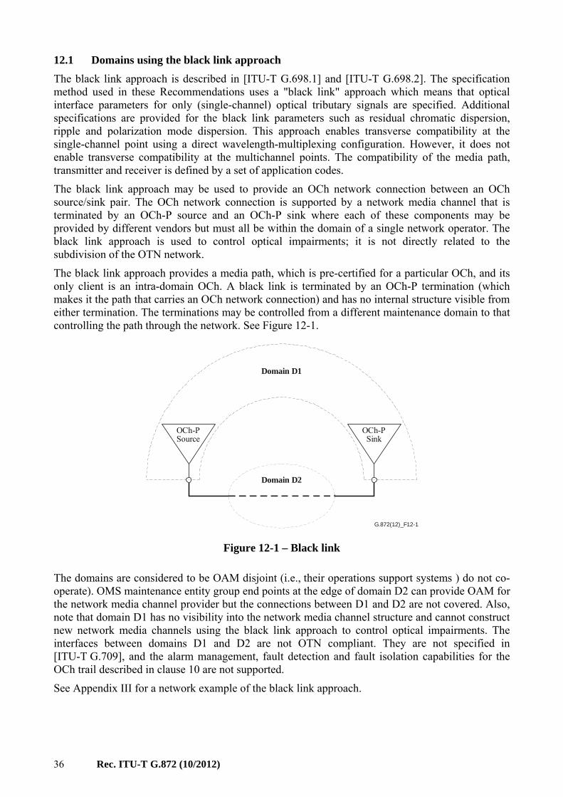
36 Rec. ITU-T G.872 (10/2012)
12.1 Domains using the black link approach
The black link approach is described in [ITU-T G.698.1] and [ITU-T G.698.2]. The specification method used in these Recommendations uses a "black link" approach which means that optical interface parameters for only (single-channel) optical tributary signals are specified. Additional specifications are provided for the black link parameters such as residual chromatic dispersion, ripple and polarization mode dispersion. This approach enables transverse compatibility at the single-channel point using a direct wavelength-multiplexing configuration. However, it does not enable transverse compatibility at the multichannel points. The compatibility of the media path, transmitter and receiver is defined by a set of application codes.
The black link approach may be used to provide an OCh network connection between an OCh source/sink pair. The OCh network connection is supported by a network media channel that is terminated by an OCh-P source and an OCh-P sink where each of these components may be provided by different vendors but must all be within the domain of a single network operator. The black link approach is used to control optical impairments; it is not directly related to the subdivision of the OTN network.
The black link approach provides a media path, which is pre-certified for a particular OCh, and its only client is an intra-domain OCh. A black link is terminated by an OCh-P termination (which makes it the path that carries an OCh network connection) and has no internal structure visible from either termination. The terminations may be controlled from a different maintenance domain to that controlling the path through the network. See Figure 12-1.
G.872(12)_F12-1
OCh-PSource
OCh-PSink
Domain D1
Domain D2
Figure 12-1 – Black link
The domains are considered to be OAM disjoint (i.e., their operations support systems ) do not co-operate). OMS maintenance entity group end points at the edge of domain D2 can provide OAM for the network media channel provider but the connections between D1 and D2 are not covered. Also, note that domain D1 has no visibility into the network media channel structure and cannot construct new network media channels using the black link approach to control optical impairments. The interfaces between domains D1 and D2 are not OTN compliant. They are not specified in [ITU-T G.709], and the alarm management, fault detection and fault isolation capabilities for the OCh trail described in clause 10 are not supported.
See Appendix III for a network example of the black link approach.

Rec. ITU-T G.872 (10/2012) 37
Appendix I
Examples of multi-domain OTN applications
(This appendix does not form an integral part of this Recommendation.)
This appendix provides examples of multi-domain OTN applications.
Figure I.1 illustrates the case of interconnection of two disjoint domains (domain A) through another domain (domain B). Domain A has requested an ODUi service from domain B. This ODUi service from domain A's perspective is an HO ODUi, carrying multiple LO ODUk signals. This same ODUi service from domain B's perspective is an LO ODUi of which the end points are outside the domain of domain B. Within domain B's network the LO ODUi is carried over an HO ODUj.
G.872(12)_FI-1
ODUi ODUi
ODUj ODUj
ODUi/ODUk ODUi/ODUk
ODUj/ODUi ODUj/ODUi
ODUk SNC ODUk SNC
ODUi SNC ODUi SNC
ODUj trail
ODUi trail
Domain B
Domain ADomain A
OTN IrDI OTN IrDI
Figure I.1 – Multi-domain OTN scenario 1

38 Rec. ITU-T G.872 (10/2012)
Figure I.2 illustrates the above case with additional TCM function.
G.872(12)_FI-2
ODUi ODUi
ODUj ODUj
ODUi/ODUk ODUi/ODUk
ODUj/ODUi ODUj/ODUi
ODUk SNC ODUk SNC
ODUi SNC ODUi SNC
ODUj trail
ODUi trail
Domain B
Domain ADomain A
OTN IrDI OTN IrDI
ODUi TCM trail
ODUi MP ODUi MP
Figure I.2 – Multi-domain OTN scenario 2
Figure I.3 illustrates the case of server ODUi of domain A carried as a client ODUj in domain B directly over OTUj in domain B.
G.872(12)_FI-3
ODUi ODUi
OTUj OTUj
ODUi/ODUk ODUi/ODUk
OTUj/ODUi OTUj/ODUi
ODUk SNC ODUk SNC
ODUi SNC ODUi SNC
ODUj trail
ODUi trail
Domain B
Domain ADomain A
OTN IrDI OTN IrDI
Figure I.3 – Multi-domain OTN scenario 3

Rec. ITU-T G.872 (10/2012) 39
Appendix II
Construction of optical channel connections
(This appendix does not form an integral part of this Recommendation.)
This appendix describes the order of construction of topology entities culminating in the establishment of a network media channel. This description focuses mainly on the spectrum configuration entities and does not discuss establishing all the necessary maintenance entities.
The initial topology is a set of media channel matrices interconnected by fibres. The available media channels are determined by the granularity of the filters around the matrix. In some cases, the granularity can be configured.
Media channel matrix connections are set up to establish a new topology of media channels interconnecting a subset of the matrices. Administratively, the spectrum capacity allocated to the new media channel is removed from the total fibre capacity. By further filter configuration, the media channel capacity can later be administratively allocated for smaller media channels.
The next step is to set up a network media channel across the previously constructed topology. When a media matrix channel request traverses a matrix in a previously established media matrix channel, no action is required to configure the matrix; however, the request should be verified against the existing media matrix channel. When the new channel request traverses an un-configured matrix, the media matrix channel must be set up. In both cases an OCh-O OAM forwarding relationship must be set up on the network element so that an OCh-O non-associated overhead can be correctly forwarded. While configuring OAM forwarding and switching the network media channel could occur at different times, it is most likely that a single configuration request will perform both OAM and media matrix operations at the same time.
Now that a network media channel exists across the network, an OCh-P signal can now be launched and any non-associated overhead will be forwarded to the OCh-O sink.
Note that this description refers to information needed to manage resource usage in the network. There is no implication as to where this information resides in the network.
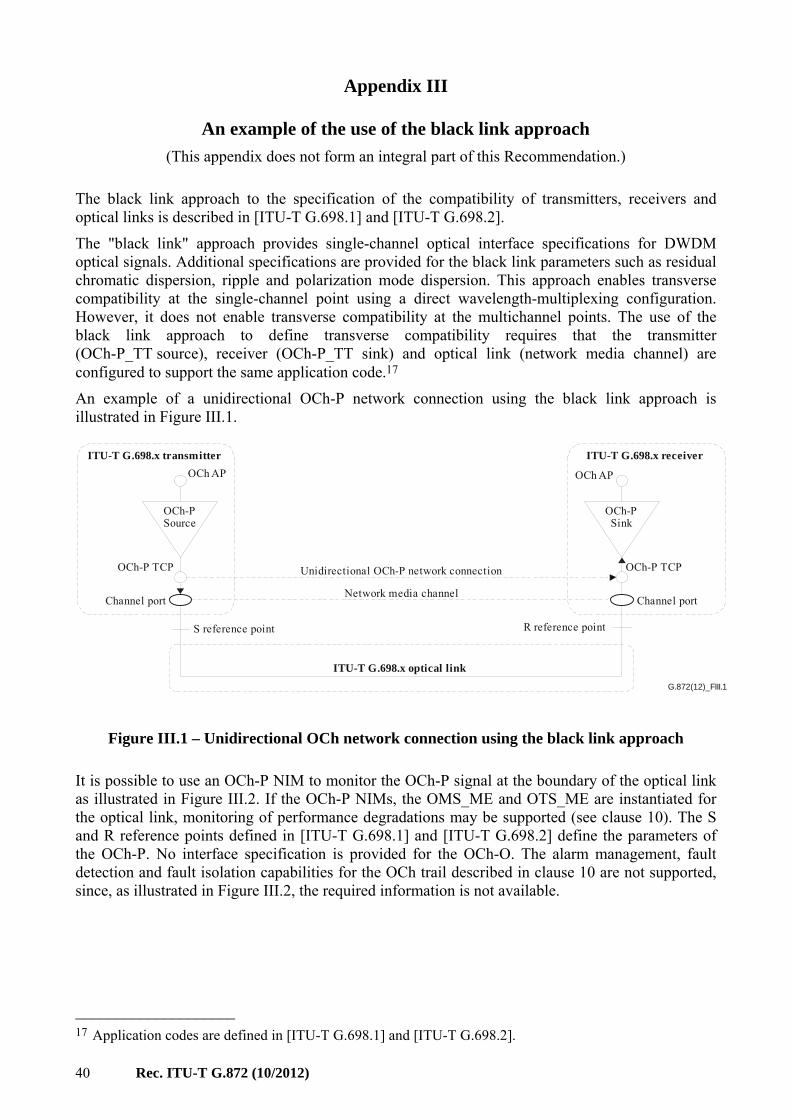
40 Rec. ITU-T G.872 (10/2012)
Appendix III
An example of the use of the black link approach
(This appendix does not form an integral part of this Recommendation.)
The black link approach to the specification of the compatibility of transmitters, receivers and optical links is described in [ITU-T G.698.1] and [ITU-T G.698.2].
The "black link" approach provides single-channel optical interface specifications for DWDM optical signals. Additional specifications are provided for the black link parameters such as residual chromatic dispersion, ripple and polarization mode dispersion. This approach enables transverse compatibility at the single-channel point using a direct wavelength-multiplexing configuration. However, it does not enable transverse compatibility at the multichannel points. The use of the black link approach to define transverse compatibility requires that the transmitter (OCh-P_TT source), receiver (OCh-P_TT sink) and optical link (network media channel) are configured to support the same application code.17
An example of a unidirectional OCh-P network connection using the black link approach is illustrated in Figure III.1.
G.872(12)_FIII.1
OCh-PSink
OCh-PSource
OCh AP OCh AP
OCh-P TCP
Channel portChannel port
OCh-P TCP Unidirectional OCh-P network connection
Network media channel
ITU-T G.698.x transmitter ITU-T G.698.x receiver
S reference point R reference point
ITU-T G.698.x optical link
Figure III.1 – Unidirectional OCh network connection using the black link approach
It is possible to use an OCh-P NIM to monitor the OCh-P signal at the boundary of the optical link as illustrated in Figure III.2. If the OCh-P NIMs, the OMS_ME and OTS_ME are instantiated for the optical link, monitoring of performance degradations may be supported (see clause 10). The S and R reference points defined in [ITU-T G.698.1] and [ITU-T G.698.2] define the parameters of the OCh-P. No interface specification is provided for the OCh-O. The alarm management, fault detection and fault isolation capabilities for the OCh trail described in clause 10 are not supported, since, as illustrated in Figure III.2, the required information is not available.
____________________ 17 Application codes are defined in [ITU-T G.698.1] and [ITU-T G.698.2].

Rec. ITU-T G.872 (10/2012) 41
G.872(12)_FIII.2
OCh-PNIM
OCh-PNIM
OCh-PSink
OCh-PSource
OCh AP OCh AP
OCh-P TCP
Channel portChannel port
OCh-P TCP Unidirectional OCh-P network connection
Network media channel
ITU-T G.698.x transmitter ITU-T G.698.x receiver
S reference point R reference point
ITU-T G.698.x optical link
OCh-OSink
OCh-O trail
OCh-O network connection
OCh-OSource
OCh-O TCPOCh-O TCP
SISI
Figure III.2 – Unidirectional OCh network connection using the black link approach with a monitored optical link

42 Rec. ITU-T G.872 (10/2012)
Appendix IV
Relationship between Recommendations ITU-T G.872 and ITU-T G.798
(This appendix does not form an integral part of this Recommendation.)
This appendix describes the relationship between the model provided in this Recommendation and the existing functions and processes described in [ITU-T G.798]. Figure IV.1 illustrates that the additions to this Recommendation that support configurable media elements and the ability to manage the media at a granularity that is greater than a single OCh-P have no effect on processes defined in [ITU-T G.798].

Rec. ITU-T G.872 (10/2012) 43
G.872(12)_FIV.1
OCh/OTU
OCh_AI
OCh-P
OCh-P_CI
OCh-P_CI
OCh-P
OCh-P_CI
SI
Coordination
OCh-Pfilter
OMS-P_CI
OMS-P_CI
OMS-PNIM
OCh-O
OCh-O_CI
OCh-O
OCh-O_CI
OCh-O(de)aggregator
OMS-O_AI
SI
SI
OMS-O
OMS-O_CI
OTS-O/OMS-O
OTS-O_AI
OTS-O
OSC/OTS-O
OSC
OTS-PNIM
OSCfilter
OTS-CI
OCh-PNIM
OCh-P/OTUOCh/OTU
OCh-P
OCh-PNIM
OCh-OH
OCh_TCP
OCh_CP
OMS_AP
OTS_AP
OMS_TCP
OCh_CI_P
OCh_CI_P
OMS_AI_P
OTS_AI_P
OMS_CI_P
OCh_CI_OH/..
OCh_CI_OH/..
OMS_AI_OH/..
OTS_AI_OH/..
OMS_CI_OH/..
OCh-P OCh-OHOCh
OCh
OCh-OH(de)aggregator
OTS-OH/OMS-OH
OCh-Pfilter
OTS-P
OMS/OCh
OTS/OMS
OMS-PNIM
OTS-PNIM
OMS-OH
OTS-OH
OSC
OMS
OTS
OSCfilter
OSC/OTS-OH
OTS_TCP
OMS-P_CI
OCh_AP
OCh_AI
Figure IV.1 – Relationship between ITU-T G.872 and ITU-T G.798
Note that the reference points in the right hand (ITU-T G.798) column are references in both the signal and OAM paths. The ITU-T G.798 reference point is shown dotted, with the two components inside it.


Printed in Switzerland Geneva, 2013
SERIES OF ITU-T RECOMMENDATIONS
Series A Organization of the work of ITU-T
Series D General tariff principles
Series E Overall network operation, telephone service, service operation and human factors
Series F Non-telephone telecommunication services
Series G Transmission systems and media, digital systems and networks
Series H Audiovisual and multimedia systems
Series I Integrated services digital network
Series J Cable networks and transmission of television, sound programme and other multimedia signals
Series K Protection against interference
Series L Construction, installation and protection of cables and other elements of outside plant
Series M Telecommunication management, including TMN and network maintenance
Series N Maintenance: international sound programme and television transmission circuits
Series O Specifications of measuring equipment
Series P Terminals and subjective and objective assessment methods
Series Q Switching and signalling
Series R Telegraph transmission
Series S Telegraph services terminal equipment
Series T Terminals for telematic services
Series U Telegraph switching
Series V Data communication over the telephone network
Series X Data networks, open system communications and security
Series Y Global information infrastructure, Internet protocol aspects and next-generation networks
Series Z Languages and general software aspects for telecommunication systems