t0 - aapct - e&i - report - power reticulation system.pdf
TRANSCRIPT

Report on Power reticulation system Abbot Point Coal Export Terminal T-0 Expansion (X120)
1 SUMMARY REPORT (E&I)
D E C - 2 0 1 2
R E P O R T O N
P O W E R R E T I C U L AT I O N S Y S T E M
A B B O T P O I N T C O A L T E R M I N A L T- 0 E X PA N S I O N
D R A F T R E P O R T
1 2 - D E C - 1 2 R E V : 0

Report on Power reticulation system Abbot Point Coal Export Terminal T-0 Expansion (X120)
2 SUMMARY REPORT (E&I)
TABLE OF CONTENTS
1.0 INTRODUCTION ....................................................................................................................................................... 3 2.0 EXECUTIVE SUMMARY ............................................................................................................................................ 3
2.1 DOCUMENT PURPOSE ................................................................................................................................... 3 2.2 EVALUATION / STUDY .................................................................................................................................... 3 2.3 CONCLUSION .................................................................................................................................................. 3 LIMITATIONS ............................................................................................................................................................ 4
3.0 SYSTEM INTRODUCTION ......................................................................................................................................... 5 4.0 OPTION-I AS PER BASIC ENGINEERING .................................................................................................................. 6
3.1 CONCEPT NOTES ............................................................................................................................................ 6 3.2 QUANTIFICATION OF ELECTRICAL ITEMS/EQUIPMENTS ............................................................................ 7 3.3 MERITS & DEMERITS OF PROPOSED SCHEME ............................................................................................. 7 3.4 BULLET POINT ................................................................................................................................................ 8
5.0 OPTION-II SUGGESTED BY BMT WBM ASSOCIATES .............................................................................................. 9 4.1 CONCEPT NOTES ............................................................................................................................................ 9 4.2 QUANTIFICATION OF ELECTRICAL ITEMS/EQUIPMENTS .......................................................................... 11 4.3 MERITS & DEMERITS OF PROPOSED SCHEME ........................................................................................... 11 4.4 BULLET POINT .............................................................................................................................................. 11
6.0 AN ALTERNATE, OPTION-III................................................................................................................................... 12 5.1 CONCEPT NOTES .......................................................................................................................................... 12 5.2 QUANTIFICATION OF ELECTRICAL ITEMS/EQUIPMENTS .......................................................................... 13 5.3 MERITS & DEMERITS OF PROPOSED SCHEME ........................................................................................... 13 5.4 BULLET POINT .............................................................................................................................................. 14
7.0 VFD SCHEME SELECTION ...................................................................................................................................... 15 6.1 CONCEPT NOTES ......................................................................................................................................... 15 6.1 BULLET POINTS ............................................................................................................................................ 15
8.0 SUMMARY ................................................................................................................................................................ 2 9.0 RECOMMENDATION ............................................................................................................................................... 3

Report on Power reticulation system Abbot Point Coal Export Terminal T-0 Expansion (X120)
3 SUMMARY REPORT (E&I)
1.0 INTRODUCTION
Abbot Point Coal Terminal is situated at Queensland state on east coast of Australia. Adani Abbot Point Coal Terminal (AAPCT) Pty Ltd is intended to create certain Common User Facilities, Common Maneuvering Area, facilities for Material Handling System and facilities specific for handling Bulk cargo carriers on Berth-3 under T0 expansion at AAPCT (QLD).
2.0 EXECUTIVE SUMMARY
2.1 DOCUMENT PURPOSE
The purpose of this document is to evaluate overall Electrical reticulation system most suitable in terms of technical reliability as well as overall economics for T0 expansion at AAPCT. There are 3 (Three) options available for proposed Electrical reticulation system out of which one is to be finalized that can fulfill above mentioned aspects. a) Option - I b) Option - II c) Option - III This document details high level Schematic Description, Quantifications, Advantages and Disadvantages of all three available options.
2.2 EVALUATION / STUDY
The evaluation is mainly focused on three areas;
Installation feasibility System reliability Operation & Maintenance convenience Economics involved
2.3 CONCLUSION
PARAMETER MOST SUITABLE SCHEME REMARK Installation cost / feasibility
Option-III
Reliability of electrical system
Option-III
Reliability of continuity of port operation.
Option-II Scheme can provide reliability against fault on LT section or fault/hazard on individual switchroom. If fault on PDC will create similar condition that may happen in case of fault/hazard on substation in other options. Also, it has to checked with operation philosophy.

Report on Power reticulation system Abbot Point Coal Export Terminal T-0 Expansion (X120)
4 SUMMARY REPORT (E&I)
Cost of installation Option-III (Based on quantification as per annex-I) Convenience of installation
Option-III LV Cabling / Cable tray installation is reduced. Dimensions of prefabricated s/s building are less.
Looking at the overall comparison between various options, we recommend option-III for proposed power reticulation system.
LIMITATIONS
This report will exclude detail technical explanation/details. Information included in this report is based on references, discussion with vendors. This report excludes electrical design parameters evaluation, detailed calculations etc.

Report on Power reticulation system Abbot Point Coal Export Terminal T-0 Expansion (X120)
5 SUMMARY REPORT (E&I)
3.0 SYSTEM INTRODUCTION
The project shall include 1 (one) dedicated berth capable of handling of dry bulk/coal with necessary back up yard and facilities. The main elements/facilities of proposed terminal project under phase-I are;
Rail receiving / Dump station Conveyor system with Back up facilities Surge bin System 1 (one) bulk handling berth
The installation of Electrical & Instrumentation system facility for above mentioned elements/facilities is to be carried out in accordance with applicable codes, standards, acts & regulations. Power supply at 66kV (primary source voltage) shall be tapped from nearest source of power from the network governed by Local power supply authority/network operator and shall be brought at 66kV Switchyard (AIS). Power shall be stepped down at required voltage level through Main Power Transformers for further distribution at Main substation located adjacent to 66kV Switchyard. The options for Electrical reticulation system proposed by various parties need to be evaluated from the point of stepped down voltage level.

Report on Power reticulation system Abbot Point Coal Export Terminal T-0 Expansion (X120)
6 SUMMARY REPORT (E&I)
4.0 OPTION-I AS PER BASIC ENGINEERING
Electrical reticulation system proposed in Option-I is illustrated as shown in block diagram. Refer Fig 3.1 In scheme proposed in Option-I, power is being stepped down to 11kV for further distribution.
Table 3.1
DESCRIPTION VOLTAGE LEVEL REMARK Incoming power 66kV At Switchyard Primary distribution 11kV From Main S/S to area S/S Secondary distribution 3.3kV Distribution for conveyor motors Stacker re-claimer 11kV Ship loader 11kV VFD input/output voltage 3.3kV/3.3kV Conveyor motors 3.3kV LV distribution 0.415kV
3.1 CONCEPT NOTES
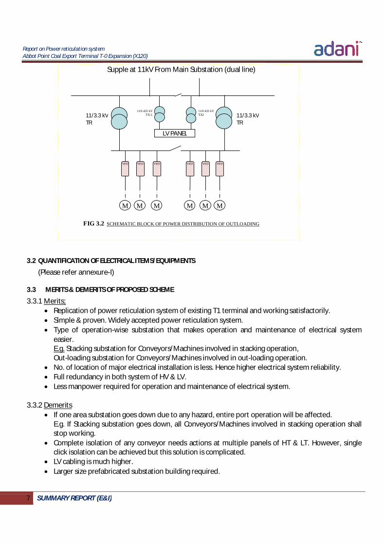
Replication of power reticulation system of existing T1 terminal. Main substation to receive power at 11kV. All other area substations to receive power at 11kV from Main substation bus. (See Fig 3.1) Each substations including Main substation to have 11/3.3kV Transformers (redundant) to feed MV
conveyor motors through Variable Frequency drive (VFD) within vicinity of the substation. (See Fig 3.2) Each substations including Main substation to have 11/0.415kV Transformers (redundant) to feed LV loads within vicinity of the substation. (See Fig 3.2)
VFD for conveyor motors to be housed at substation buildings. Each substation to have PLC facility. However Main PLC with control room to be at Main substation. Highest distance between VFD and Conveyor motor is approx. 1300 Mtr. Highest dimensions of prefabricated substation building required is approximately 25 mtr x 12 Mtr x
3.5 Mtr (LxWxH) excluding transformers.
MAIN SUBSTATION
WHARF SUBSTATION
RAIL RECEIVING
SUBSTATION-2
OUTLOADING SUBSTATION
STACKING SUBSTATION
RAIL RECEIVING
SUBSTATION-1 INLOADING SUBSTATION
FIG 3.1 SCHEMATIC BLOCK OF POWER DISTRIBUTION (HIGH LEVEL)
Phase-I (11kV) Final Phase (11kV)
Detail Fig 3.2
Report on Power reticulation system Abbot Point Coal Export Terminal T-0 Expansion (X120)
7 SUMMARY REPORT (E&I)
FIG 3.2 SCHEMATIC BLOCK OF POWER DISTRIBUTION OF OUTLOADING
3.2 QUANTIFICATION OF ELECTRICAL ITEMS/EQUIPMENTS
(Please refer annexure-I)
3.3 MERITS & DEMERITS OF PROPOSED SCHEME
3.3.1 Merits; Replication of power reticulation system of existing T1 terminal and working satisfactorily. Simple & proven. Widely accepted power reticulation system. Type of operation-wise substation that makes operation and maintenance of electrical system
easier. E.g. Stacking substation for Conveyors/Machines involved in stacking operation, Out-loading substation for Conveyors/Machines involved in out-loading operation.
No. of location of major electrical installation is less. Hence higher electrical system reliability. Full redundancy in both system of HV & LV. Less manpower required for operation and maintenance of electrical system.
3.3.2 Demerits If one area substation goes down due to any hazard, entire port operation will be affected.
E.g. If Stacking substation goes down, all Conveyors/Machines involved in stacking operation shall stop working.
Complete isolation of any conveyor needs actions at multiple panels of HT & LT. However, single click isolation can be achieved but this solution is complicated.
LV cabling is much higher. Larger size prefabricated substation building required.
LV PANEL
VFD
M
11/3.3 kV TR
11/3.3 kV TR
M M M M M
VFD
VFD
VFD
VFD
VFD
11/0.433 kV TX-1
11/0.433 kV TX2
Supple at 11kV From Main Substation (dual line)

Report on Power reticulation system Abbot Point Coal Export Terminal T-0 Expansion (X120)
8 SUMMARY REPORT (E&I)
3.4 BULLET POINT
Existing T1 terminal power reticulation system was of conveyor motors without VFD. Basic engineering design does not describe type of VFDs to be used for Conveyor motors.
Handling facility of large size prefabricated substation to be considered at project site.

Report on Power reticulation system Abbot Point Coal Export Terminal T-0 Expansion (X120)
9 SUMMARY REPORT (E&I)
5.0 OPTION-II SUGGESTED BY BMT WBM ASSOCIATES
Electrical reticulation system proposed in Option-II is illustrated as shown in block diagram. Refer Fig 4.1 In scheme proposed in Option-II, power is being stepped down to 22kV for further distribution.
DESCRIPTION VOLTAGE LEVEL REMARK Incoming power 66kV At Switchyard Primary distribution 22kV From Main S/S to area S/S Secondary distribution 6.6kV Distribution for conveyor motors Stacker re-claimer 22kV or 6.6kV Ship loader 22kV or 6.6kV VFD input/output voltage 6.6kV Conveyor motors 6.6kV LV distribution 0.415kV
4.1 CONCEPT NOTES
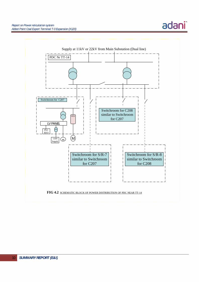
Power to be stepped down at 22kV at Main substation. All power distribution center (PDC) located across the plant shall be fed from Main substation at
22kV. (Similar to scheme proposed as per Option-I but at 22kV) Power to be further stepped down at 6.6kV at PDCs for further distribution to individual
switchrooms located around the site adjacent to respective plant item (Conveyor motor or machine). Refer Fig 4.2
LV loads shall be supplied through a non-redundant 6.6/0.415kV Transformers located at each switchroom.
All switchrooms shall have PLC facility and to be connected to main PLC at Main substation. Highest distance between VFD and Conveyor motor is 150 Mtr. Highest dimensions of prefabricated substation building required is approximately 35 mtr x 15 Mtr x
3.5 Mtr (LxWxH) excluding transformers. FIG 4.1 SCHEMATIC BLOCK OF POWER DISTRIBUTION – OPTION-III SCHMEME (HIGHLEVEL)
MAIN SUBSTATION (66/22kV or 66/11kV)
PDC Nr TT-14
PDC Nr TT-15A PDC Nr TT-22
PDC Nr TT-24 PDC Nr TT-18
PDC Nr TT-12 Phase-I (22kV)
Final phase (22kV) Detail Fig 4.2
Report on Power reticulation system Abbot Point Coal Export Terminal T-0 Expansion (X120)
10 SUMMARY REPORT (E&I)
FIG 4.2 SCHEMATIC BLOCK OF POWER DISTRIBUTION OF PDC NEAR TT-14
Supply at 11kV or 22kV from Main Substation (Dual line)
VFD
M
LV PANEL
m 110V Supply
PLC RI/O
PDC Nr TT-14
Switchroom for C207
Switchroom for C208 similar to Switchroom
for C207
Switchroom for S/R-7 similar to Switchroom
for C207
Switchroom for S/R-8 similar to Switchroom
for C208

Report on Power reticulation system Abbot Point Coal Export Terminal T-0 Expansion (X120)
11 SUMMARY REPORT (E&I)
4.2 QUANTIFICATION OF ELECTRICAL ITEMS/EQUIPMENTS
(Please refer annexure-I)
4.3 MERITS & DEMERITS OF PROPOSED SCHEME
4.3.1 Merits: Single point isolation can be achieved for each conveyor / machine of the plant. Hence
conveyor/machine maintenance can be carried out very easily. Hazard / fault on one switchroom or fault at LV system to affect operation of one particular
conveyor. Hence less effect on overall plant operation. LV cabling & cable tray reduces considerably and becomes simple. Transportation and handling of prefabricated substation building at project site is convenient as
building sizes smaller. Immediate isolation of particular conveyor can be performed in case of emergency when
centralized control system gets failed. Saving in HV cable as 22kV distribution to require less sizes of MV cable to cater same amount of
load than 11kV distribution.
4.3.2 Demerits: Supply & Installation cost is higher than other reticulation options in terms of No of prefabricated
substations, No. of HT Switchgears, No. of Transformers, PLC-RIO and HV cables. Unavailability of LV power to be observed on complete isolation of Conveyor system for
maintenance. Incomer breaker for LV transformer has to be kept on for availability of LV power for conveyor system maintenance then Option-II scheme is no different than other reticulations system proposed as per Option-I. This case diminishes advantage in Option-II regarding complete isolation of Conveyor up to much extent.
No redundancy of LV system Maintenance and operation of electrical system to become difficult as number of Major electrical
equipment installation is much higher. Hence, more manpower required for operation and maintenance.
Frequency of occurrence of fault likely to increase due as number of Major electrical equipment installation is much higher.
Absence of mechanical brakes limits VFD options available. Hence, it is observed that proposed Option-II scheme not to perform any value addition in VFD system by putting VFDs nearer to Motor.
4.4 BULLET POINT
Option-II suggested by BMT WBM scheme does not describe type of VFDs to be used for Conveyor motors.
Possibility of entire port operation to be on stop in case of outing of any area substation due to any hazard in reticulation scheme proposed as per Option-I. Similar situation may arise with scheme proposed in Option-II in case of outing of any PDC or Main substation.
Report on Power reticulation system Abbot Point Coal Export Terminal T-0 Expansion (X120)
12 SUMMARY REPORT (E&I)
6.0 AN ALTERNATE, OPTION-III
Electrical reticulation system proposed in Option-III is illustrated as shown in block diagram. Refer Fig 5.1 In scheme proposed in Option-III, power is being stepped down to 11kV for further distribution.
DESCRIPTION VOLTAGE LEVEL REMARK Incoming power 66kV At Switchyard Primary distribution 11kV From Main S/S to area S/S Secondary distribution 11kV For conveyor motors (VFDs) Stacker re-claimer 11kV Ship loader 11kV VFD input/output voltage 11kV/3.3kV Conveyor motors 3.3kV LV distribution 0.415kV
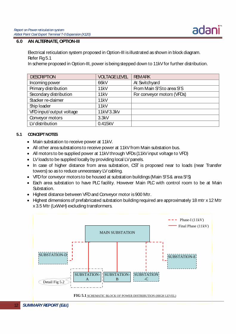
5.1 CONCEPT NOTES
Main substation to receive power at 11kV. All other area substations to receive power at 11kV from Main substation bus. All motors to be supplied power at 11kV through VFDs (11kV input voltage to VFD) LV loads to be supplied locally by providing local LV panels. In case of higher distance from area substation, CST is proposed near to loads (near Transfer
towers) so as to reduce unnecessary LV cabling. VFD for conveyor motors to be housed at substation buildings (Main S/S & area S/S) Each area substation to have PLC facility. However Main PLC with control room to be at Main
Substation. Highest distance between VFD and Conveyor motor is 900 Mtr. Highest dimensions of prefabricated substation building required are approximately 18 mtr x 12 Mtr
x 3.5 Mtr (LxWxH) excluding transformers.
MAIN SUBSTATION
SUBSTATION-B
SUBSTATION-E
SUBSTATION-A
SUBSTATION-D
SUBSTATION-C
FIG 5.1 SCHEMATIC BLOCK OF POWER DISTRIBUTION (HIGH LEVEL)
Phase-I (11kV) Final Phase (11kV)
Detail Fig 5.2

Report on Power reticulation system Abbot Point Coal Export Terminal T-0 Expansion (X120)
13 SUMMARY REPORT (E&I)
FIG 5.2 SCHEMATIC BLOCK OF POWER DISTRIBUTION OF SUBSTATION-A
5.2 QUANTIFICATION OF ELECTRICAL ITEMS/EQUIPMENTS
(Please refer annexure-I)
5.3 MERITS & DEMERITS OF PROPOSED SCHEME
5.3.1 Merits; Simple & proven. Widely accepted power reticulation system. Reduced number of substation building, elimination of 11/3.3kV transformer and other electrical
installation keeps overall system installation cost lower. Full redundancy in system of HV & LV. No. of location of major electrical installation is less. Hence higher electrical system reliability. Easy in maintenance and operation of electrical system. Less manpower required for operation and maintenance of electrical system.
11/0.433 kV TR
11/0.433 kV TR
Supply at 11kV From Main Substation (dual line)
LT PANEL AT SUBSTATION-A
LV LOAD ENGAGED
WITH CONV-1
LV LOAD ENGAGED
WITH CONV-2
LV LOAD ENGAGED
WITH CONV-3
LV LOAD ENGAGED
WITH CONV-4
VFD
M
VFD
M
VFD
M
VFD
M
VFD
M
VFD
M

Report on Power reticulation system Abbot Point Coal Export Terminal T-0 Expansion (X120)
14 SUMMARY REPORT (E&I)
5.3.2 Demerits If one area substation goes down, entire port operation will be affected. Single point isolation is not available. However, Single LV cubicle is placed to supply LV load engaged
with that conveyor. Hence, isolation can be achieved with reasonably easy interlocking. LV cable requirement is higher than scheme proposed in Option-II. Larger size prefabricated substation building required.
5.4 BULLET POINT
Handling facility of large size prefabricated substation to be considered at project site.

Report on Power reticulation system Abbot Point Coal Export Terminal T-0 Expansion (X120)
15 SUMMARY REPORT (E&I)
7.0 VFD SCHEME SELECTION
6.1 CONCEPT NOTES
All conveyor motors to have VFDs. Mechanical brakes are not included in conveyor system hence dynamic braking is to become an
essential feature to have with VFD system. VFDs shall be housed in air-conditioned room. Major parameter for selection of VFD system appropriate for conveyor system to be dynamic
braking. Major parameters for selection of VFD system appropriate for power reticulation system to be
distance between VFD and motor (Harmonics), Voltage level options available. There are below mentioned types of VFD system (12 pulse or higher) are available in market that
may suitable to proposed reticulation system; 1) 12 Pulse VFD with outdoor inverter transformer (Oil type) 2) 12 Pulse VFD with in-built inverter transformer (Dry type) 3) VFD with Multilevel voltage output. (18 pulse in case of 3.3kV) 4) VFD with Active front end
6.1 BULLET POINTS
Max distance between VFD and Motor for various scheme proposed by various agencies are as below; Option-I : 1200 Mtr (Approx) Option-II : 150 Mtr (Approx) Option-III : 900 Mtr (Approx)
Option-I (Basic engineering) and Option-II input documents do not describe type of VFD system to be used that is suitable to its power reticulation system.
Report on Power reticulation system Abbot Point Coal Export Terminal T-0 Expansion (X120)
i SUMMARY REPORT (E&I)
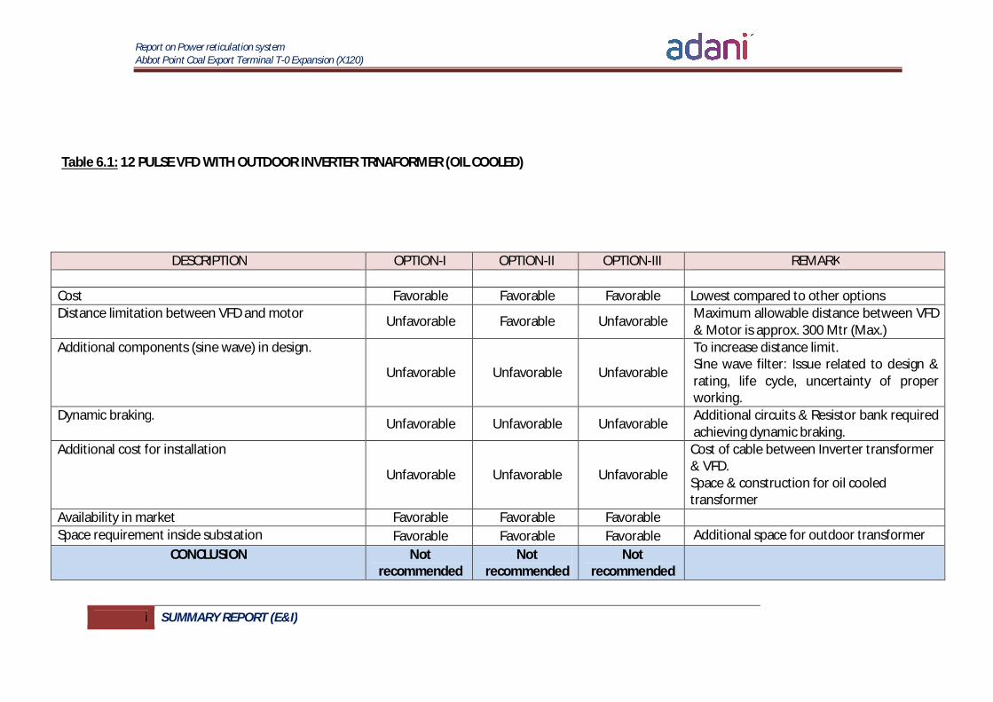
Table 6.1: 12 PULSE VFD WITH OUTDOOR INVERTER TRNAFORMER (OIL COOLED)
DESCRIPTION OPTION-I OPTION-II OPTION-III REMARK
Cost Favorable Favorable Favorable Lowest compared to other options Distance limitation between VFD and motor Unfavorable Favorable Unfavorable Maximum allowable distance between VFD
& Motor is approx. 300 Mtr (Max.) Additional components (sine wave) in design.
Unfavorable Unfavorable Unfavorable
To increase distance limit. Sine wave filter: Issue related to design & rating, life cycle, uncertainty of proper working.
Dynamic braking. Unfavorable Unfavorable Unfavorable
Additional circuits & Resistor bank required achieving dynamic braking.
Additional cost for installation
Unfavorable Unfavorable Unfavorable
Cost of cable between Inverter transformer & VFD. Space & construction for oil cooled transformer
Availability in market Favorable Favorable Favorable Space requirement inside substation Favorable Favorable Favorable Additional space for outdoor transformer
CONCLUSION Not recommended
Not recommended
Not recommended
Report on Power reticulation system Abbot Point Coal Export Terminal T-0 Expansion (X120)
ii SUMMARY REPORT (E&I)
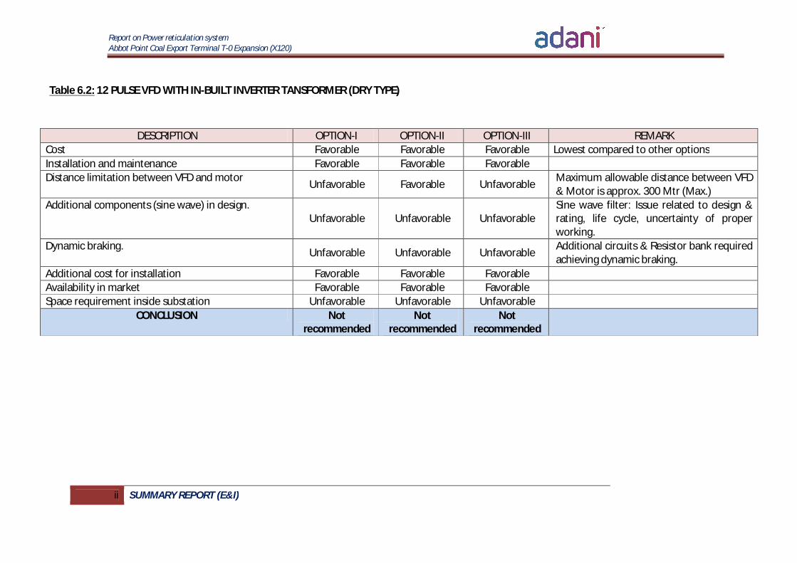
Table 6.2: 12 PULSE VFD WITH IN-BUILT INVERTER TANSFORMER (DRY TYPE)
DESCRIPTION OPTION-I OPTION-II OPTION-III REMARK Cost Favorable Favorable Favorable Lowest compared to other options Installation and maintenance Favorable Favorable Favorable Distance limitation between VFD and motor Unfavorable Favorable Unfavorable Maximum allowable distance between VFD
& Motor is approx. 300 Mtr (Max.) Additional components (sine wave) in design.
Unfavorable Unfavorable Unfavorable Sine wave filter: Issue related to design & rating, life cycle, uncertainty of proper working.
Dynamic braking. Unfavorable Unfavorable Unfavorable Additional circuits & Resistor bank required achieving dynamic braking.
Additional cost for installation Favorable Favorable Favorable Availability in market Favorable Favorable Favorable Space requirement inside substation Unfavorable Unfavorable Unfavorable
CONCLUSION Not recommended
Not recommended
Not recommended
Report on Power reticulation system Abbot Point Coal Export Terminal T-0 Expansion (X120)
iii SUMMARY REPORT (E&I)
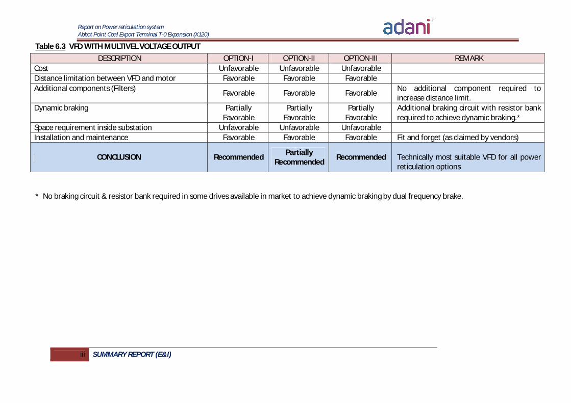
Table 6.3 VFD WITH MULTIVEL VOLTAGE OUTPUT
* No braking circuit & resistor bank required in some drives available in market to achieve dynamic braking by dual frequency brake.
DESCRIPTION OPTION-I OPTION-II OPTION-III REMARK Cost Unfavorable Unfavorable Unfavorable Distance limitation between VFD and motor Favorable Favorable Favorable Additional components (Filters) Favorable Favorable Favorable No additional component required to
increase distance limit. Dynamic braking Partially
Favorable Partially
Favorable Partially
Favorable Additional braking circuit with resistor bank required to achieve dynamic braking.*
Space requirement inside substation Unfavorable Unfavorable Unfavorable Installation and maintenance Favorable Favorable Favorable Fit and forget (as claimed by vendors)
CONCLUSION Recommended Partially Recommended Recommended
Technically most suitable VFD for all power reticulation options

Report on Power reticulation system Abbot Point Coal Export Terminal T-0 Expansion (X120)
iv SUMMARY REPORT (E&I)
Table 6.1 VFD WITH ACTIVE FRONT END
DESCRIPTION OPTION-I OPTION-II OPTION-III REMARK
Cost Unfavorable Unfavorable Unfavorable Distance limitation between VFD and motor Unfavorable Unfavorable Unfavorable No distance limit Additional components (Filters) Favorable Favorable Favorable No additional component required to
increase distance limit. Dynamic braking Favorable Favorable Favorable Space requirement inside substation Favorable Favorable Favorable Installation and maintenance Favorable Favorable Favorable Fit and forget (as claimed by vendors)
CONCLUSION Not Recommended Recommended Not
Recommended

Report on Power reticulation system Abbot Point Coal Export Terminal T-0 Expansion (X120)
1 SUMMARY REPORT (E&I)
CONCLUSION:
From Above description in table 6.1, 6.2, 6.3 & 6.4, it may be observed that; VFD with multilevel output seems only option available that is suitable for Power reticulation scheme proposed Option-I &
Option-III. VFD with multilevel output may be recommended for Power reticulation scheme proposed Option-II as it does not perform
any value addition to system by keeping VFDs near to conveyor motors. Hence, VFD with active front end is suitable for power reticulation scheme proposed in Option-II.

Report on Power reticulation system Abbot Point Coal Export Terminal T-0 Expansion (X120)
2 SUMMARY REPORT (E&I)
8.0 SUMMARY
The report shows that scheme proposed for power reticulation is dependent on reliability of electrical system / reliability of port operation, Installation cost / feasibility, ease of operation & maintenance of Electrical system including VFDs, type of VFD system,. Overall summary of the report is illustrated in table 7.1
7.1 OPTION-I AS PER BASIC ENGINEERING
Option-I is replication of power reticulation of existing T1 terminal that is in operation satisfactorily. But conveyor motors are without VFDs that puts the proposed reticulation system. As illustrated in table 6.3, VFD option is available for Option-I scheme to run satisfactorily. System cost is lower than scheme proposed in Option-II yet higher than Option-III.
7.2 OPTION-II SUGGESTED BY BMT WBM
Option-II scheme primarily focuses on conveyor system isolation and local operation that looked fair for operation reliability/continuity in case of any fault. But as described in report (4.3.1), there are certain demerits in proposed system that cannot be overlooked. Referring to quantification, Option-II scheme seems a costliest option out of all three. Also, as illustrated in Point 6.0, costlier VFD system has to be used even though VFDs are placed within allowable distance between VFD & Motor due to achieve dynamic braking in absence of mechanical brakes.
7.3 AN ALTERNATE, OPTION-III
Option-III scheme is alike to Option-I of basic engineering scheme. It covers major benefits of full redundancy, lowest cost out of all other options, conveyor isolation by simple interlocking. Lesser number of locations for major electrical installations gives better reliability.

Report on Power reticulation system Abbot Point Coal Export Terminal T-0 Expansion (X120)
3 SUMMARY REPORT (E&I)
9.0 RECOMMENDATION
The study shows that Option-III scheme for Power reticulation is most suitable in terms of technical reliability, operation and maintenance convenience as well as overall economics for T0 expansion at AAPCT. Hence, we recommend Option-III for its benefits as summarized in report.
10.0 ANNEXURE-I Annexure-I is attached.