t14sg software update manual - ripmax · t14sg software update manual ... an alarm sounds when...
TRANSCRIPT

T14SG SOFTWARE UPDATE MANUAL
[Updating procedure]
1. SD card format1. You should format the SD card first by using T14SG. When the SD card is formatted,
all the data is deleted. Please do not format it when there is critical data.
2. Please turn on power switch of T14SG. If the SD card not formatted is set, the following screen is displayed. Please select "FORMAT" by scroll operation of touch sensor and touch “RTN” .
3. Please select "YES" and touch “RTN” .
4. The following screen is displayed during formatting.
5. When the format is completed, the following screen is displayed.
6. Please turn off power switch and detach the SD card from card slot.
2. Making of card for soft update1. Please unzip the zipped file. The following files will create.
・T14sgUpdate.exe ... File copy utility・T14sgUpdate.dat ... Information file for T14sgUpdate.exe ・T14SG_UPDATE.dat … Identified file of T14SG ・T14SG_TS.bin ... Update file of T14SG (piece 3) ・T14SG_AP.bin ... Update file of T14SG (piece 2) ・T14SG_UPLD.bin ... Update file of T14SG (piece 1)
① Push to open.②Slide in the direction of the arrow on the battery cover.
③ Battery cover will open downward. ④ SD card is inserted in a slot by direction of a figure.
SD card slot
-1-

2. Please attach the SD card formatted to the card reader of PC. 3. Please run "T14sgUpdate.exe". 4. Please select the drive that attached the SD card. Click the "OK" button.
5. Please select the drive that attached the SD card. Click the "OK" button.
6. Update files is copied to SD card, the following screens are displayed. Click "END" button.
Update
-2-
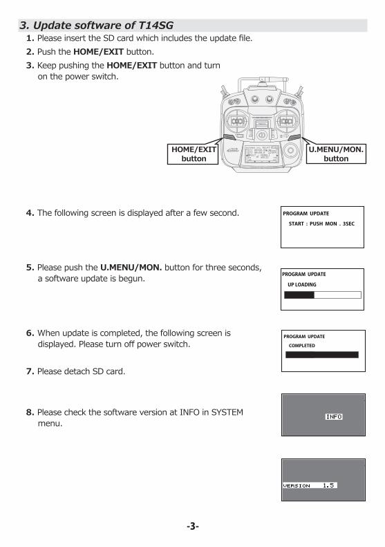
3. Update software of T14SG 1. Please insert the SD card which includes the update file.2. Push the HOME/EXIT button. 3. Keep pushing the HOME/EXIT button and turn
on the power switch.
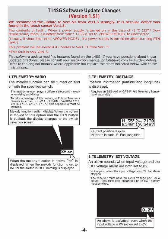
4. The following screen is displayed after a few second.
5. Please push the U.MENU/MON. button for three seconds, a software update is begun.
6. When update is completed, the following screen is displayed. Please turn off power switch.
7. Please detach SD card.
8. Please check the software version at INFO in SYSTEM menu.
HOME/EXITbutton
U.MENU/MON.button
PROGRAM UPDATE
START : PUSH MON . 3SEC
PROGRAM UPDATE
UP LOADING
-3-
PROGRAM UPDATE
COMPLETED
-4-
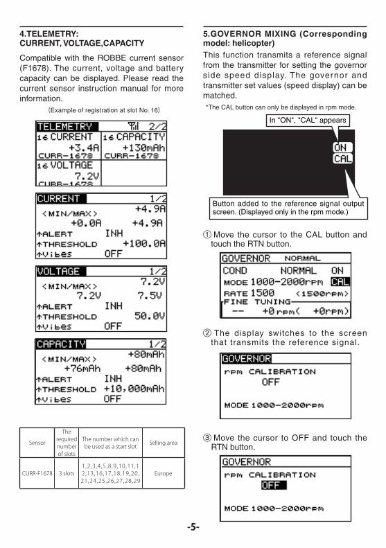
1.TELEMETRY: VARIOThe melody function can be turned on and off with the specified switch.*The melody function plays a different electronic melody when rising and diving.
*To take advantage of this feature, a Futaba Telemetry Sensor (such as SBS-01A, SBS-01G, VARIO-F1712, VARIO-F1672 or GPS-F1672, sold separately) must be installed.
2. TELEMETRY: DISTANCEPosition information (latitude and longitude) is displayed.*Requires an SBS-01G or GPS-F1762 Telemetry Sensor (sold separately).
3. TELEMETRY: EXT VOLTAGEAn alarm sounds when input voltage and the EXT voltage alarm are both set to 0V.*In the past, when the input voltage was 0V, the alarm stopped.
*The receiver must have an Extra Voltage port, or a sensor (SBS-01V) sold separately or an EXT battery must be wired.
When the melody function is active, “on” is displayed. When the melody function is set to INH or the switch is OFF, nothing is displayed.
Melody function switch display. When the cursor is moved to this option and the RTN button is pushed, the display changes to the switch selection screen.
Current position display.N: North latitude, E: East longitude
An alarm is activated, even when the input voltage is 0V (when set to 0V).
T14SG Software Update Changes(Version 1.51)
We recommend the update to Ver1.51 from Ver1.5 strongly. It is because defect was found in the touch sensor Ver1.5.The contents of fault : When a power supply is turned on in the case of -5 ℃ (23°F )low temperature, there is a defect from which 14SG is set to <POWER MODE> to unexpected.(Usually, it should be set to <POWER MODE>, if a power supply is turned on after touching RTN next.)This problem will be solved if it updates to Ver1.51 from Ver1.5. *This fault is only Ver1.5.This software update modifies features found on the 14SG. If you have questions about these updated directions, please consult your instruction manual or futaba-rc.com for further details. Refer to the original manual where applicable but replace the steps indicated below with these instructions.
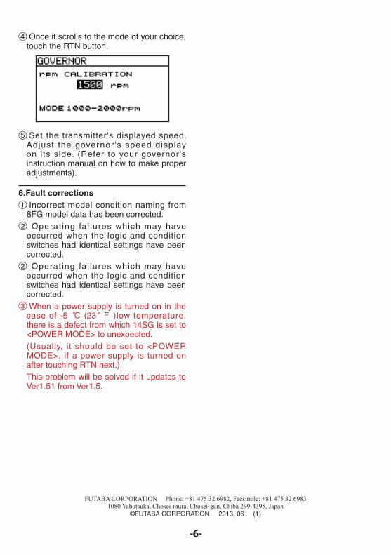
4.TELEMETRY: CURRENT, VOLTAGE,CAPACITY
Compatible with the ROBBE current sensor (F1678). The current, voltage and battery capacity can be displayed. Please read the current sensor instruction manual for more information. (Example of registration at slot No. 16)
Sensor
The required number of slots
The number which can be used as a start slot Selling area
CURR-F1678 3 slots1,2 ,3 ,4 ,5 ,8 ,9 ,10,11,12,13,16,17,18,19,20,21,24,25,26,27,28,29
Europe
5.GOVERNOR MIXING (Corresponding model: helicopter)This function transmits a reference signal from the transmitter for setting the governor side speed display. The governor and transmitter set values (speed display) can be matched.*The CAL button can only be displayed in rpm mode.
① Move the cursor to the CAL button and touch the RTN button.
② The display switches to the screen that transmits the reference signal.
③ Move the cursor to OFF and touch the RTN button.
Button added to the reference signal output screen. (Displayed only in the rpm mode.)
In "ON", "CAL" appears
-5-
FUTABA CORPORATION Phone: +81 475 32 6982, Facsimile: +81 475 32 69831080 Yabutsuka, Chosei-mura, Chosei-gun, Chiba 299-4395, Japan
©FUTABA CORPORATION 2013, 06 (1)
-6-
④ Once it scrolls to the mode of your choice, touch the RTN button.
⑤ Set the transmitter's displayed speed. Adjust the governor's speed display on its side. (Refer to your governor's instruction manual on how to make proper adjustments).
6.Fault corrections① Incorrect model condition naming from
8FG model data has been corrected.② Operat ing fai lures which may have
occurred when the logic and condition switches had identical settings have been corrected.② Operat ing fai lures which may have
occurred when the logic and condition switches had identical settings have been corrected.③When a power supply is turned on in the
case of -5 ℃ (23°F )low temperature, there is a defect from which 14SG is set to <POWER MODE> to unexpected.(Usually, it should be set to <POWER MODE>, if a power supply is turned on after touching RTN next.)This problem will be solved if it updates to Ver1.51 from Ver1.5.