t1s-sig#51
TRANSCRIPT

7/30/2019 T1S-SIG#51
http://slidepdf.com/reader/full/t1s-sig51 1/61
3GPP TSG-T1/SIG SWG meeting #5 TSG T1S#5-99xxxKobe, Japan13-14 September 1999,
1
Agenda Item:
Source: Matsushita Communication Industrial(Panasonic), NTT DoCoMo
Title: RRC
Document for: Discussion
Introduction
This document is RRC signaling test specification based on the belows for RELEASE99.
Reference TS25.331 RRC Protocol Specification V 1.2.1
TS25.303 UE Functions and Interlayer Procedures in Connected Mode V 3.0.0
TS25.304 UE Procedures in Idel Mode V 1.3.1
TR25.922 Radio Resource Management Strategies V 0.2.1
TR25.931 UTRAN Functions, Examples on Signalng Procedure V 1.1.1
3GPP

7/30/2019 T1S-SIG#51
http://slidepdf.com/reader/full/t1s-sig51 2/61
3GPP TSG-T1/SIG SWG meeting #5 TSG T1S#5-99xxxKobe, Japan13-14 September 1999,
2
8 Layer 3
8.1 Radio Resource Control(RRC)
8.1.1 Idle Mode
8.1.1.1 Idle Mode : Paging
8.1.1.1.1 Paging for Connection
8.1.1.1.2 Paging for Notification
8.1.1.2 Idle Mode : Notification
8.1.2RRC Connection
8.1.2.1 RRC Connection Establishment
8.1.2.1.1 RRC Connection Establishment:Success
8.1.2.1.2 RRC Connection Establishment:Failure (No Response)
8.1.2.1.3 RRC Connection Establishment:Reject
8.1.2.1.4 RRC Connection Re-Establishment:Radio link Failure
8.1.2.2 RRC Connection Release
8.1.2.2.1 RRC Connection Release:DCH
8.1.2.2.2 RRC Connection Release:FACH/RACH
8.1.3RRC Connected Mode
8.1.3.1 RRC Connected Mode : Radio Access Bearer Establishment
8.1.3.1.1 Radio Access Bearer Establishment with dedicated physical
channel activation
8.1.3.1.2 Radio Access Bearer Establishment with unsynchronised
dedicated physical channel modification
8.1.3.1.3 Radio Access Bearer Establishment with synchronised dedicated physical
channel modification
3GPP

7/30/2019 T1S-SIG#51
http://slidepdf.com/reader/full/t1s-sig51 3/61
3GPP TSG-T1/SIG SWG meeting #5 TSG T1S#5-99xxxKobe, Japan13-14 September 1999,
3
8.1.3.1.4 Radio Access Bearer Establishment without dedicated physical channel
8.1.3.2 RRC Connected Mode : Radio Access Bearer Release
8.1.3.2.1 Radio Access Bearer Release with unsynchronised dedicated physical
channel modification
8.1.3.2.2 Radio Access Bearer Release with synchronised dedicated physical
channel modification
8.1.3.2.3 Radio Access Bearer Release without dedicated physical channel
modification
8.1.3.3 RRC Connected Mode : Radio Access Bearer Reconfiguration
8.1.3.3.1 Synchronised Radio Access Bearer Reconfiguration
8.1.3.3.2 Unsynchronised Radio Access Bearer Reconfiguration
8.1.3.4 RRC Connected Mode : Physical Channel Reconfiguration
8.1.3.4.1 Assignment of dedicated physical channel
8.1.3.4.2 Synchronised replacement(modification) of dedicated physical channel
8.1.3.4.3 Release dedicated physical channel
8.1.3.4.4 To add further FAUSCH
8.1.3.5 RRC Connected Mode : Transport Channel Reconfiguration
8.1.3.5.1 Synchronised transport format set reconfiguration
8.1.3.5.2 Unsynchronised transport format set reconfiguration
8.1.3.5.3 Pre-configuration of TFS/TFCS for a transport channel not yet in use
8.1.3.6 RRC Connected Mode : Transport format combination Control
8.1.4Mobility in RRC connected mode
8.1.4.1 Soft Handover
8.1.4.1.1 Radio link addition
8.1.4.1.2 Radio link removal
8.1.4.1.3 Combined radio link addition and removal
3GPP

7/30/2019 T1S-SIG#51
http://slidepdf.com/reader/full/t1s-sig51 4/61
3GPP TSG-T1/SIG SWG meeting #5 TSG T1S#5-99xxxKobe, Japan13-14 September 1999,
4
8.1.4.2 Hard Handover
8.1.4.2.1 Inter frequency hard handover
8.1.4.2.2 Inter system hard handover(GSM/BSS to UTRAN)
8.1.4.2.3 Inter system hard handover(UTRAN to GSM/BSS)
8.1.4.3 Cell Reselection
8.1.4.3.1 Inter system(GSM to UTRAN)
8.1.4.3.2 Inter system(UTRAN to GSM/BSS)
8.1.4.4 URA Update
8.1.4.5 Cell Update
8.1.4.6 RNTI Reallocation
8.1.5Others in RRC connected mode
8.1.5.1 Core network originating paging
8.1.5.1.1 UTRAN coordinated paging using DCCH
8.1.5.1.2 UTRAN coordinated paging using PCCH
8.1.5.1.3 UE coordinated paging
8.1.5.2 UTRAN originated paging
8.1.5.3 Measurement Control and Report
8.1.5.4 System Information in RRC connected mode
8.1.5.5 Direct Transfer
8.1.5.6 RRC Status Procedure
8.1.5.7 UE Capability Enquiry
8.1.6Ciphering
3GPP

7/30/2019 T1S-SIG#51
http://slidepdf.com/reader/full/t1s-sig51 5/61
3GPP TSG-T1/SIG SWG meeting #5 TSG T1S#5-99xxxKobe, Japan13-14 September 1999,
5
8.1 Radio Resource Control(RRC(8.1.1 Idle Mode
8.1.1.1 Idle Mode : Paging
8.1.1.1.1 Paging for Connection
8.1.1.1.1.1 Conformance requirement
・This procedure is used to broadcast a PAGING TYPE 1 message from the network to selected UEs which are in
idle mode. Only UEs which listen to the correct paging group can be reached by this procedure.
Reference
3GPP TS 25.331 clause 8.1.2
8.1.1.1.1.2 Test purpose
To confirm that after receiving a PAGING TYPE1 message which includes its identifier for the UE in the idle
state, the UE establishes an RRC connection.
8.1.1.1.1.3 Method of test
Initial Condition
System Simulator : 1 cell
UE :.The UE is in the idle state with a IMSI, TMSI, or P-TMSI.
Foreseen Final state of the UE
RRC Connected State
Test Procedure
The SS sends a PAGING TYPE1 message which includes a different IMSI, TMSI or P-TMSI. The UE does not
change its state (idle state). The SS sends a PAGING TYPE1 message which includes a correct IMSI ,TMSI or P-
TMSI.Then the UE sends an RRC CONNECTION REQUEST to the SS, the SS sends an RRC CONNECTION
SETUP to the UE. When the UE receives this message, the UE shall establishes an RRC connection.
Maximum duration of the test
FFS
Expected sequence
Step Direction Message Comment
SS MS
3GPP

7/30/2019 T1S-SIG#51
http://slidepdf.com/reader/full/t1s-sig51 6/61
3GPP TSG-T1/SIG SWG meeting #5 TSG T1S#5-99xxxKobe, Japan13-14 September 1999,
6
1 PAGING TYPE1 The SS sends the message
includes a different identifier,
then the UE does not change its
2 PAGING TYPE1 The SS sends the message
3 RRC CONNECTION REQUEST
4 RRC CONNECTION SETUP An RRC connection is
8.1.1.1.2 Paging for Notification
8.1.1.1.2.1 Conformance requirement
・When a system information blocks on the BCCH is modified, the message PAGING TYPE1 can be sent on the
PCCH to inform UE’s about the changes. The message includes the information element BCCH Modification
Information.
Reference
3GPP TS 25.331 clause 8.1.1
8.1.1.1.2.2 Test purpose
To confirm that after receiving a PAGING TYPE1 message which includes the information element BCCH
Modification Information, the UE listens to and follows the SYSTEM INFORMATION.
8.1.1.1.2.3 Method of test
Initial Condition
System Simulator : 1 cell
UE : The UE is in the idle state with a IMSI, TMSI, or P-TMSI.
Foreseen Final state of the UE
Listening to a SYSTEM INFORMATION
Test Procedure
The UE is in the idle state before changing SYSTEM INFORMATION. Then the SS modifies its SYSTEM
INFORMATION. After a while the SS sends a PAGING TYPE1 message which includes the information element
BCCH Modification Information. The UE listens to the modified SYSTEM INFORMATION. The UE follows the
modified message.
Maximum duration of the test
FFS
3GPP

7/30/2019 T1S-SIG#51
http://slidepdf.com/reader/full/t1s-sig51 7/61
3GPP TSG-T1/SIG SWG meeting #5 TSG T1S#5-99xxxKobe, Japan13-14 September 1999,
7
Expected sequence
Step Direction Message Comment
SS MS
1 SYSTEM INFORMATION The SS changes its SYSTEM
INFORMATION when the UE is
2 PAGING TYPE 1 SS sends the message includes
the information element BCCH
3 SYSTEM INFORMATION The UE listens to the SYSTEM
INFORMATION and then the
8.1.1.2 Idle Mode : Notification
8.1.1.2.1 Conformance requirement
・This procedure is used for broadcast of notification information to selected UEs in a cell. Only UEs that listen
to the correct notification group can be reached by this procedure. The initiative to send a NOTIFICATION can
come from both the access stratum and the non-access stratum. NOTIFICATION can be sent to either one or
many UEs at the same time.
Reference
3GPP TS 25.331 clause 8.1.3
The bellows are FFS.
8.1.1.2.2 Test purpose
8.1.1.2.3 Method of test
Initial Condition
FFS
Foreseen Final state of the UE
FFS
3GPP

7/30/2019 T1S-SIG#51
http://slidepdf.com/reader/full/t1s-sig51 8/61
3GPP TSG-T1/SIG SWG meeting #5 TSG T1S#5-99xxxKobe, Japan13-14 September 1999,
8
Test Procedure
FFS
Maximum duration of the test
FFS
Expected sequence
Step Direction Message Comment
SS MS
3GPP

7/30/2019 T1S-SIG#51
http://slidepdf.com/reader/full/t1s-sig51 9/61
3GPP TSG-T1/SIG SWG meeting #5 TSG T1S#5-99xxxKobe, Japan13-14 September 1999,
9
8.1.2 RRC Connection
8.1.2.1 RRC Connection Establishment
8.1.2.1.1 RRC Connection Establishment :Success
8.1.2.1.1.1 Conformance requirement
( The RRC connection establishment is initiated by the UE, which leaves the idle mode and sends an RRC
CONNECTION REQUEST message using unassured mode on the uplink CCCH.
・After receiving RRC CONNECTION SETUP message which includes radio resource parameters and RNTI, the
UE configures the layer 2 and layer 1 processing required to support the DCCH according to the radio resource
parameters. The procedure successfully ends when the network receives an RRC CONNECTION SETUP
COMPLETE message.
Reference
3GPP TS 25.331 clause 8.2.1
8.1.2.1.1.2 Test purpose
To confirm that the UE leaves the Idle Mode and correctly establishes a signaling link on the DCCH.
8.1.2.1.1.3 Method of test
Initial Condition
System Simulator : 1 cell
UE: Idle state
Foreseen Final state of the UE
RRC Connected State
Test Procedure
The UE sends an RRC CONNECTION REQUEST message to the SS using uplink CCCH by outgoing call
operation. After receiving this message, the SS makes an assignment of radio resources and RNTI to be used by
the UE and the SS sends an RRC CONNECTION SETUP message to the UE. Then the UE configures L2 and L1
on the DCCH and sends an RRC CONNECTION SETUP COMPLETE message.
Maximum duration of the test
FFS
3GPP

7/30/2019 T1S-SIG#51
http://slidepdf.com/reader/full/t1s-sig51 10/61
3GPP TSG-T1/SIG SWG meeting #5 TSG T1S#5-99xxxKobe, Japan13-14 September 1999,
10
Expected sequence
Step Direction Message Comment
SS MS1 RRC CONNECTION REQUEST By outgoing call operation
2 RRC CONNECTION SETUP
3 RRC CONNECTION SETUP
8.1.2.1.2 RRC Connection Establishment :Failure(No response)
8.1.2.1.2.1 Conformance requirement
( The RRC connection establishment is initiated by the UE, which leaves the idle mode and sends an RRC
CONNECTION REQUEST message using unassured mode on the uplink CCCH.
・ In the case of a failure to establish the RRC connection for lack of response from the network the UE goes back
to Idle Mode.
Reference
3GPP TS 25.331 clause 8.2.1
TS 25.303 clause 5.4.2
8.1.2.1.2.2 Test purpose
To confirm that the UE goes back to Idle Mode when the SS sends no response for RRC connection request.
8.1.2.1.2.3 Method of test
Initial Condition
System Simulator : 1 cell
UE: Idle state
Foreseen Final state of the UE
RRC Idle State
3GPP

7/30/2019 T1S-SIG#51
http://slidepdf.com/reader/full/t1s-sig51 11/61
3GPP TSG-T1/SIG SWG meeting #5 TSG T1S#5-99xxxKobe, Japan13-14 September 1999,
11
Test Procedure
The UE sends RRC CONNECTION REQUEST message to the SS using uplink CCCH by outgoing call
operation. The SS ignores this message and takes no action to confirm that finally the UE goes back to the idlestate.
Maximum duration of the test
FFS
Expected sequence
Step Direction Message Comment
SS MS
1 RRC CONNECTION REQUEST By outgoing call operation
2 No response to the UE
3GPP

7/30/2019 T1S-SIG#51
http://slidepdf.com/reader/full/t1s-sig51 12/61
3GPP TSG-T1/SIG SWG meeting #5 TSG T1S#5-99xxxKobe, Japan13-14 September 1999,
12
8.1.2.1.3 RRC Connection Establishment :Reject
8.1.2.1.3.1 Conformance requirement
( The RRC connection establishment is initiated by the UE, which leaves the idle mode and sends an RRC
CONNECTION REQUEST message using unassured mode on the uplink CCCH.
・ In the case of a failure to establish the RRC connection by receiving a reject response message from the
network, the UE goes back to Idle Mode.
Reference
3GPP TS 25.331 clause 8.2.1
TS 25.303 clause 5.4.2
8.1.2.1.3.2 Test purpose
To confirm that the UE goes back to Idle Mode, if the SS sends an RRC CONNECTION REJECT message.
8.1.2.1.3.3 Method of test
Initial Condition
System Simulator : 1 cell
UE : Idle state
Test Procedure
The UE sends RRC CONNECTION REQUEST message to the SS using uplink CCCH by outgoing call
operation. After receiving this message the SS sends an RRC CONNECTION REJECT message. To confirm that
finally the UE goes back to the idle state.
Maximum duration of the test
FFS
Expected sequence
Step Direction Message Comment
SS MS
1 RRC CONNECTION REQUEST By outgoing
call operation
2 RRC CONNECTION REJECT
3GPP

7/30/2019 T1S-SIG#51
http://slidepdf.com/reader/full/t1s-sig51 13/61
3GPP TSG-T1/SIG SWG meeting #5 TSG T1S#5-99xxxKobe, Japan13-14 September 1999,
13
8.1.2.1.4 RRC Connection Re-Establishment :Radio link failure
8.1.2.1.4.1 Conformance requirement
( The RRC connection establishment is initiated by the UE, which leaves the idle mode and sends an RRC
CONNECTION REQUEST message using unassured mode on the uplink CCCH.
・RRC connection re-establishment is needed, when a UE loses the radio connection due to e.g. radio link failure.
After a new cell has been selected, the UE RRC sends the NW RRC an RRC CONNECTION RE-
ESTABLISHMENT REQUEST message. The NW RRC configures the NW and acknowledges the connection
re-establishment to the UE RRC with an RRC CONNECTION RE-ESTABLISHMENT message.
Reference
3GPP TS 25.331 clause 8.2.1 clause 8.2.3
8.1.2.1.4.2 Test purpose
To confirm that the UE tries to find a new cell and to establish an RRC connection again using an RRC
CONNNECTION RE-ESTABLISHMENT REQUEST message after the radio link failure at the first RRC
connection establishment procedure, finally the UE establishes an RRC connection link.
8.1.2.1.4.3 Method of test
Initial Condition
System Simulator : 2 cells(cell No.1,cell No.2(
UE: Idle state in the cell No.1
Foreseen Final state of the UE
RRC connected state in the cell No.2
Test Procedure
The SS broadcasts a BCCH in a cell No.1.The UE sends an RRC CONNECTION REQUEST message to the SS
using uplink CCCH by outgoing call operation. After receiving this message, the SS makes an assignment of radio
resources and RNTI to be used by the UE. Then the SS sends an RRC CONNECTION SETUP message to UE.
But the SS does not configure the new radio link and begins to broadcast a BCCH in a cell No.2.So the UE cannot
configure L2 and L1 on the DCCH, the UE finds a new BCCH(No.2) and sends an RRC CONNECTION RE-
ESTABLISHMENT REQUEST message to a new cell. When the SS receives this message it sends an RRC
CONNECTION RE-ESTABLISHMENT message which includes a new radio link parameters. Finally the RRC
connection is established by this parameters in a new cell( No.2(and the UE sends an RRC CONNECTION RE-
ESTABLISHMENT COMPLETE message on the DCCH.
3GPP
7/30/2019 T1S-SIG#51
http://slidepdf.com/reader/full/t1s-sig51 14/61
3GPP TSG-T1/SIG SWG meeting #5 TSG T1S#5-99xxxKobe, Japan13-14 September 1999,
14
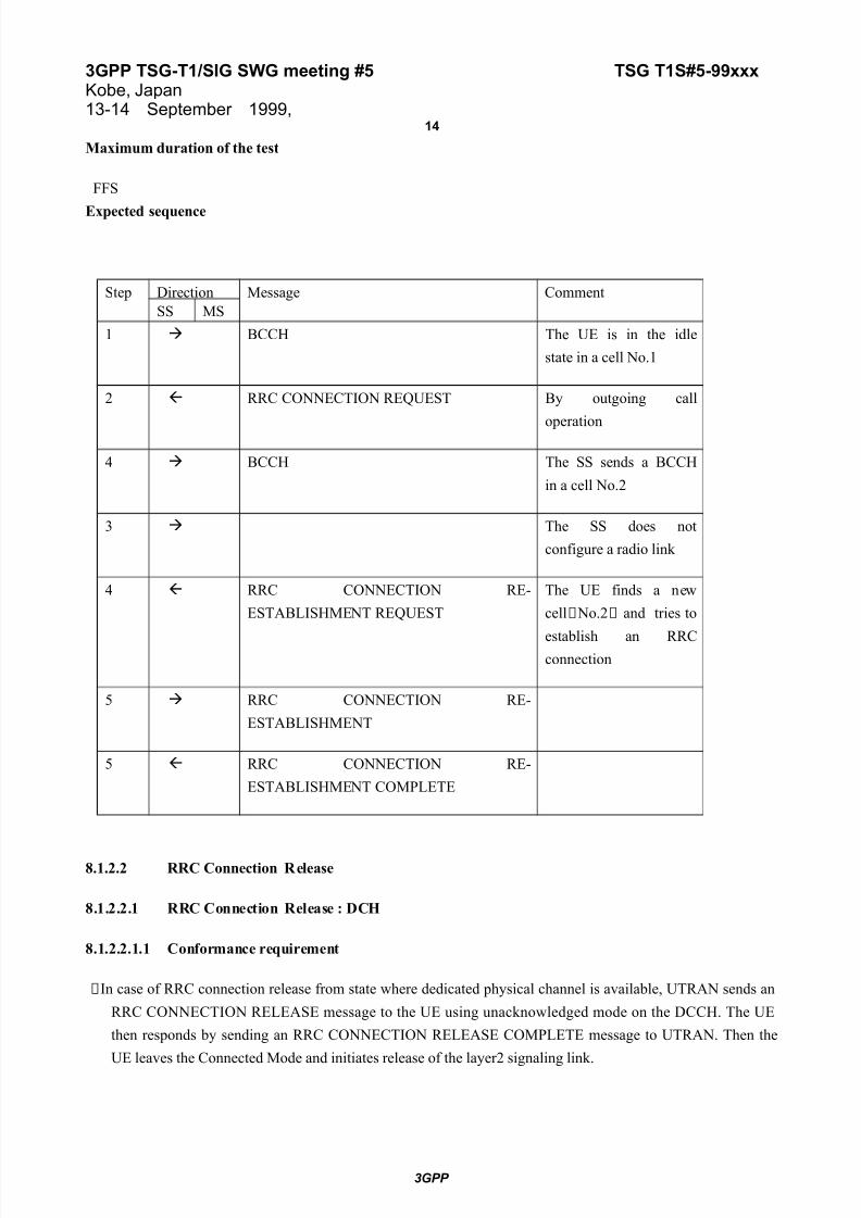
Maximum duration of the test
FFS
Expected sequence
Step Direction Message Comment
SS MS
1 BCCH The UE is in the idle
state in a cell No.1
2 RRC CONNECTION REQUEST By outgoing call
operation
4 BCCH The SS sends a BCCH
in a cell No.2
3 The SS does not
configure a radio link
4 RRC CONNECTION RE-
ESTABLISHMENT REQUEST
The UE finds a new
cell( No.2( and tries to
establish an RRCconnection
5 RRC CONNECTION RE-
ESTABLISHMENT
5 RRC CONNECTION RE-
ESTABLISHMENT COMPLETE
8.1.2.2 RRC Connection Release
8.1.2.2.1 RRC Connection Release : DCH
8.1.2.2.1.1 Conformance requirement
(In case of RRC connection release from state where dedicated physical channel is available, UTRAN sends an
RRC CONNECTION RELEASE message to the UE using unacknowledged mode on the DCCH. The UE
then responds by sending an RRC CONNECTION RELEASE COMPLETE message to UTRAN. Then the
UE leaves the Connected Mode and initiates release of the layer2 signaling link.
3GPP

7/30/2019 T1S-SIG#51
http://slidepdf.com/reader/full/t1s-sig51 15/61
3GPP TSG-T1/SIG SWG meeting #5 TSG T1S#5-99xxxKobe, Japan13-14 September 1999,
15
(The RRC Connection Release procedure ends when all UE dedicated resources(such as radio resources and
radio access bearers)tied to the RRC connection are released and the RRC layer is transferred to idle mode.
Reference
3GPP TS 25.331 clause 8.2.2
8.1.2.2.1.2 Test purpose
To confirm that the UE releases the L2 signaling link and dedicated resources and goes back to the idle state after
receiving an RRC CONNECTION RELEASE message from the SS and sending an RRC CONNECTON
RELEASE COMPLETE message to the SS.
8.1.2.2.2.3 Method of test
Initial Condition
System Simulator : 1 cell
UE : RRC connected state with DCH link
Foreseen Final state of the UE
RRC Idle State
Test Procedure
The SS sends an RRC CONNECTION RELEASE message to the UE by disconnect operation. When the UE
receives this message the UE sends an RRC CONNECTION RELEASE COMPLETE message to the SS. Finally
the UE release the L2 signaling link and dedicated resources and goes back to the idle state.
Maximum duration of the test
FFS
Expected sequence
Step Direction Message Comment
SS MS
1 Communicating with DCH
link
2 RRC CONNECTION RELEASE By disconnect operation
3 RRC CONNECTION RELEASE
COMPLETE
3GPP
7/30/2019 T1S-SIG#51
http://slidepdf.com/reader/full/t1s-sig51 16/61
3GPP TSG-T1/SIG SWG meeting #5 TSG T1S#5-99xxxKobe, Japan13-14 September 1999,
16
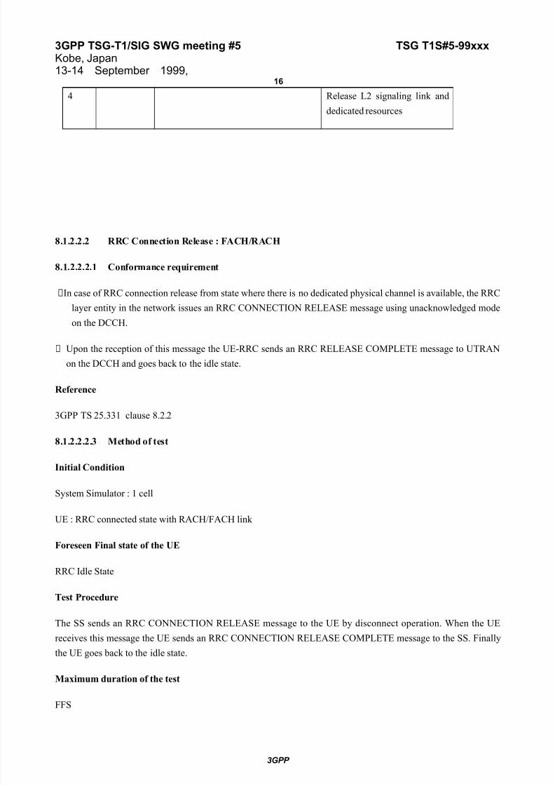
4 Release L2 signaling link and
dedicated resources
8.1.2.2.2 RRC Connection Release : FACH/RACH
8.1.2.2.2.1 Conformance requirement
(In case of RRC connection release from state where there is no dedicated physical channel is available, the RRC
layer entity in the network issues an RRC CONNECTION RELEASE message using unacknowledged mode
on the DCCH.
( Upon the reception of this message the UE-RRC sends an RRC RELEASE COMPLETE message to UTRAN
on the DCCH and goes back to the idle state.
Reference
3GPP TS 25.331 clause 8.2.2
8.1.2.2.2.3 Method of test
Initial Condition
System Simulator : 1 cell
UE : RRC connected state with RACH/FACH link
Foreseen Final state of the UE
RRC Idle State
Test Procedure
The SS sends an RRC CONNECTION RELEASE message to the UE by disconnect operation. When the UE
receives this message the UE sends an RRC CONNECTION RELEASE COMPLETE message to the SS. Finally
the UE goes back to the idle state.
Maximum duration of the test
FFS
3GPP

7/30/2019 T1S-SIG#51
http://slidepdf.com/reader/full/t1s-sig51 17/61
3GPP TSG-T1/SIG SWG meeting #5 TSG T1S#5-99xxxKobe, Japan13-14 September 1999,
17
Expected sequence
Step Direction Message Comment
SS MS1 Communicating with
2 RRC CONNECTION RELEASE By disconnect operation
3 RRC CONNECTION RELEASE
8.1.3 RRC Connected Mode
8.1.3.1 RRC Connected Mode : Radio Access Bearer Establishment
8.1.3.1.1 Radio Access Bearer Establishment with dedicated physical channel activation
8.1.3.1.1.1 Conformance requirement
・This procedure is a Radio Access Bearer Establishment with Dedicated Physical Channel activation. A Radio
Access Bearer Establishment is initiated when the RRC layer in the network sends a RADIO ACCESS
BEARER SETUP message to its peer entity. This message contains L1, MAC,RLC and Q 0S parameters. RRC
on the UE side then configures L1 and MAC and creates a new RLC entity associated with the new radio
access bearer on these Q0S parameters.
・The UE then sends a RADIO ACCESS BEARER SETUP COMPLETE message back to the network.
Reference
3GPP TS 25.331 clause 8.3.1.1
3GPP TS 25.303 clause 7.2.1.1.1
8.1.3.1.1.2 Test purpose
To confirm that the UE establishes a new radio access bearer on the DCH by following a RADIO ACCESS
BEARER SETUP message received from the UTRAN.
8.1.3.1.1.3 Method of test
Initial Condition
System Simulator : 1 cell
UE : Idle state
3GPP
7/30/2019 T1S-SIG#51
http://slidepdf.com/reader/full/t1s-sig51 18/61
3GPP TSG-T1/SIG SWG meeting #5 TSG T1S#5-99xxxKobe, Japan13-14 September 1999,
18
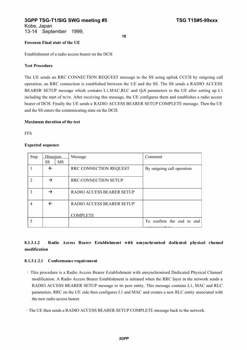
Foreseen Final state of the UE
Establishment of a radio access bearer on the DCH
Test Procedure
The UE sends an RRC CONNECTION REQUEST message to the SS using uplink CCCH by outgoing call
operation, an RRC connection is established between the UE and the SS. The SS sends a RADIO ACCESS
BEARER SETUP message which contains L1,MAC,RLC and Q0S parameters to the UE after setting up L1
including the start of tx/rx. After receiving this message, the UE configures them and establishes a radio access
bearer of DCH. Finally the UE sends a RADIO ACCESS BEARER SETUP COMPLETE message. Then the UE
and the SS enters the commnicating state on the DCH.
Maximum duration of the test
FFS
Expected sequence
Step Direction Message Comment
SS MS
1 RRC CONNECTION REQUEST By outgoing call operation
2 RRC CONNECTION SETUP
3 RADIO ACCESS BEARER SETUP
4 RADIO ACCESS BEARER SETUP
COMPLETE
5 To confirm the end to end
8.1.3.1.2 Radio Access Bearer Establishment with unsynchronised dedicated physical channel
modification
8.1.3.1.2.1 Conformance requirement
・ This procedure is a Radio Access Bearer Establishment with unsynchronised Dedicated Physical Channel
modification. A Radio Access Bearer Establishment is initiated when the RRC layer in the network sends a
RADIO ACCESS BEARER SETUP message to its peer entity. This message contains L1, MAC and RLC
parameters. RRC on the UE side then configures L1 and MAC and creates a new RLC entity associated with
the new radio access bearer.
・The UE then sends a RADIO ACCESS BEARER SETUP COMPLETE message back to the network.
3GPP

7/30/2019 T1S-SIG#51
http://slidepdf.com/reader/full/t1s-sig51 19/61
3GPP TSG-T1/SIG SWG meeting #5 TSG T1S#5-99xxxKobe, Japan13-14 September 1999,
19
Reference
3GPP TS 25.331 clause 8.3.1.1
3GPP TR 25.931 clause 9.6.2
8.1.3.1.2.2 Test purpose
To confirm that the UE establish a new radio access bearer of a compatible DCH when a radio access bearer is
already used by following a RADIO ACCESS BEARER SETUP message received from the UTRAN.
8.1.3.1.2.3 Method of test
Initial Condition
System Simulator : 1 cell
UE : RRC connected state on the DCH
Foreseen Final state of the UE
Establishment a new radio access bearer on the compatible DCHs
Test Procedure
The UE is communicating with the SS on the DCH. The SS sends a RADIO ACCESS BEARER SETUP message
which contains parameters to establish a new radio access bearer for compatible DCHs. After receiving this
message, the UE configures them and establishes a radio access bearer of DCH without synchronisation. Finally
the UE sends a RADIO ACCESS BEARER SETUP COMPLETE message. Then the UE and the SS enters the
communicating state on the DCH.
Maximum duration of the test
FFS
Expected sequence
Step Direction Message Comment
SS MS
1 A Radio access bearer is
2 RADIO ACCESS BEARER SETUP
3GPP

7/30/2019 T1S-SIG#51
http://slidepdf.com/reader/full/t1s-sig51 20/61
3GPP TSG-T1/SIG SWG meeting #5 TSG T1S#5-99xxxKobe, Japan13-14 September 1999,
20
3 RADIO ACCESS BEARER SETUP
4 To confirm the end to end
8.1.3.1.3 Radio Access Bearer Establishment with synchronised dedicated physical channel
modification
8.1.3.1.3.1 Conformance requirement
・ This procedure is a Radio Access Bearer Establishment with synchronised Dedicated Physical Channel
modification. A Radio Access Bearer Establishment is initiated when the RRC layer in the network sends a
RADIO ACCESS BEARER SETUP message to its peer entity. This message contains L1, MAC and RLC
parameters. RRC on the UE side then configures L1 and MAC and creates a new RLC entity associated with
the new radio access bearer.
・The UE then sends a RADIO ACCESS BEARER SETUP COMPLETE message back to the network.
Reference
3GPP TS 25.331 clause 8.3.1.1
3GPP TR 25.931 clause 9.6.1
8.1.3.1.3.2 Test purpose
To confirm that the UE establish a new radio access bearer of a incompatible DCH when a radio access bearer is
already used after activation time by following a RADIO ACCESS BEARER SETUP message received from the
UTRAN.
8.1.3.1.3.3 Method of test
3GPP

7/30/2019 T1S-SIG#51
http://slidepdf.com/reader/full/t1s-sig51 21/61
3GPP TSG-T1/SIG SWG meeting #5 TSG T1S#5-99xxxKobe, Japan13-14 September 1999,
21
Initial Condition
System Simulator : 1 cell
UE : RRC connected state on the DCH
Foreseen Final state of the UE
Establishment a new radio access bearer on the incompatible DCHs
Test Procedure
The UE is communicating with the SS on the DCH. The SS sends a RADIO ACCESS BEARER SETUP message
which contains parameters and an activation time to establish a new radio access bearer for incompatible DCHs.
After receiving this message, the UE configures them and establishes a radio access bearer of DCH with
synchronisation. Finally the UE sends a RADIO ACCESS BEARER SETUP COMPLETE message. Then the UE
and the SS enters the communicating state on the DCH.
Maximum duration of the test
FFS
Expected sequence
Step Direction Message CommentSS MS
1 A Radio access bearer is
established on the DCH
2 RADIO ACCESS BEARER SETUP
3 RADIO ACCESS BEARER SETUP
4 To confirm the end to end
communication
8.1.3.1.4 Radio Access Bearer Establishment without dedicated physical channel
8.1.3.1.4.1 Conformance requirement
・This procedure is Radio Access Bearer Establishment without Dedicated Physical Channel. A Radio Access
Bearer Establishment is initiated when the RRC layer in the network sends a RADIO ACCESS BEARER
SETUP message to its peer entity. This message contains L1, MAC and RLC parameters. RRC on the UE
side then configures L1 and MAC and creates a new RLC entity associated with the new radio access bearer.
・The UE then sends a RADIO ACCESS BEARER SETUP COMPLETE message back to the network.
3GPP

7/30/2019 T1S-SIG#51
http://slidepdf.com/reader/full/t1s-sig51 22/61
3GPP TSG-T1/SIG SWG meeting #5 TSG T1S#5-99xxxKobe, Japan13-14 September 1999,
22
Reference
3GPP TS 25.331 clause 8.3.1.1
3GPP TS 25.303 clause 7.2.1.1.4
8.1.3.1.4.2 Test purpose
To confirm that the UE establishes a new radio access bearer of RACH/FACH following a RADIO ACCESS
BEARER SETUP message received from the UTRAN.
8.1.3.1.4.3 Method of test
Initial Condition
System Simulator : 1 cell
UE : Idle state
Foreseen Final state of the UE
Establishment a new radio access bearer on the RACH/FACH
Test Procedure
The UE sends an RRC CONNECTION REQUEST message to the SS using uplink CCCH by outgoing call
operation, an RRC connection is established between the UE and the SS. The SS sends a RADIO ACCESS
BEARER SETUP message which contains L1,MAC and RLC parameters to the UE and configures them. After
receiving this message, the UE also configures them and establishes a radio access bearer on the RACH/FACH.
Finally the UE sends a RADIO ACCESS BEARER SETUP COMPLETE message. Then the UE and the SS
enters the communicating state on the RACH/FACH.
Maximum duration of the test
FFS
Expected sequence
Step Direction Message Comment
SS MS
1 RRC CONNECTION REQUEST By outgoing call operation
2 RRC CONNECTION SETUP
3 RADIO ACCESS BEARER SETUP
4 RADIO ACCESS BEARER SETUP
3GPP

7/30/2019 T1S-SIG#51
http://slidepdf.com/reader/full/t1s-sig51 23/61
3GPP TSG-T1/SIG SWG meeting #5 TSG T1S#5-99xxxKobe, Japan13-14 September 1999,
23
COMPLETE
5 To confirm the end to end
communication
3GPP

7/30/2019 T1S-SIG#51
http://slidepdf.com/reader/full/t1s-sig51 24/61
3GPP TSG-T1/SIG SWG meeting #5 TSG T1S#5-99xxxKobe, Japan13-14 September 1999,
24
8.1.3.2 RRC Connected Mode : Radio Access Bearer Release
8.1.3.2.1 Radio Access Bearer Release with unsynchronised dedicated physical channel modification
8.1.3.2.1.1 Conformance requirement
・This procedure is a Radio Access Bearer Release with unsynchronised dedicated physical channel modification.
A RADIO ACCESS BEARER RELEASE message is sent from the RRC layer in the network to its peer entity
in the UE. This message includes possible new L1, MAC and RLC parameters for remaining radio access
bearers and identification of the radio access bearer to be released. The RRC on the UE side configures L1 and
MAC, and releases the RLC entity associated to the released radio access bearer.
・The RRC on the UE side sends a RADIO ACCESS BEARER RELEASE COMPLETE message to the
network .
Reference
3GPP TS 25.331 clause 8.3.1.2
8.1.3.2.1.2 Test purpose
To confirm that the UE releases a radio access bearer for a DTCH and remains it for the other DTCH and DCCH
after the UE receives a RADIO ACCESS BEARER RELEASE message from the UTRAN.
8.1.3.2.1.3 Method of Test
Initial Condition
System Simulator : 1 cell
UE : RRC connected state on the DCH(DTCH(DTCH(DCH(
Foreseen Final state of the UE
To release a radio access bearer for a DTCH and remain for the other DTCH and DCCH
Test Procedure
The UE is communicating with the SS on the DCH(DTCH+DTCH+DCCH(. The SS sends a RADIO ACCESS
BEARER RELEASE message which contains identification of the radio access bearer to be released. After the
UE receives this message, the UE releases a DTCH. Finally the UE sends a RADIO ACCESS BEARER
RELEASE COMPLETE message to the SS.
Maximum duration of the test
FFS
3GPP

7/30/2019 T1S-SIG#51
http://slidepdf.com/reader/full/t1s-sig51 25/61
3GPP TSG-T1/SIG SWG meeting #5 TSG T1S#5-99xxxKobe, Japan13-14 September 1999,
25
Expected sequence
Step Direction Message Comment
SS MS
1 Radio access bearer is
established for a
communication on the
2 RADIO ACCESS BEARER RELEASE
3 RADIO ACCESS BEARER RELEASE
COMPLETE
4 To confirm to release an radio
8.1.3.2.2 Radio Access Bearer Release with synchronised dedicated physical channel modification
8.1.3.2.2.1 Conformance requirement
・This procedure is a Radio Access Bearer Release with synchronised dedicated physical channel modification. A
RADIO ACCESS BEARER RELEASE message is sent from the RRC layer in the network to its peer entity.
This message includes possible new L1, MAC, RLC and activation time parameters for remaining radio access
bearers and identification of the radio access bearer to be released. The RRC on the UE side configures L1 and
MAC, and releases the RLC entity associated to the released radio access bearer .
・The RRC on the UE side sends a RADIO ACCESS BEARER RELEASE COMPLETE message to the
network .
Reference
3GPP TS 25.331 clause 8.3.1.2
8.1.3.2.2.2 Test purpose
To confirm that the UE releases a radio access bearer for the DTCH and remains it for the DCCH after the UE
receives an RADIO ACCESS BEARER RELEASE message from the UTRAN.
8.1.3.2.2.3 Method of Test
Initial Condition
System Simulator : 1 cell
3GPP
7/30/2019 T1S-SIG#51
http://slidepdf.com/reader/full/t1s-sig51 26/61
3GPP TSG-T1/SIG SWG meeting #5 TSG T1S#5-99xxxKobe, Japan13-14 September 1999,
26
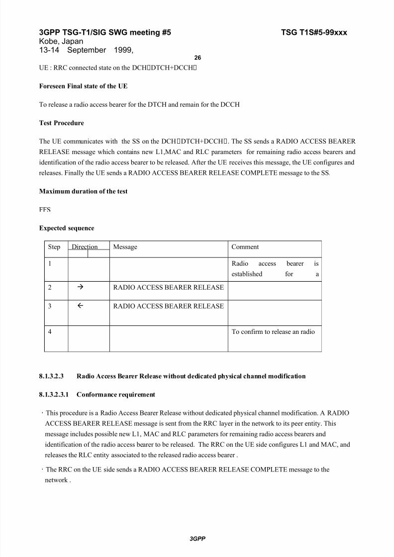
UE : RRC connected state on the DCH(DTCH+DCCH(
Foreseen Final state of the UE
To release a radio access bearer for the DTCH and remain for the DCCH
Test Procedure
The UE communicates with the SS on the DCH(DTCH+DCCH(. The SS sends a RADIO ACCESS BEARER
RELEASE message which contains new L1,MAC and RLC parameters for remaining radio access bearers and
identification of the radio access bearer to be released. After the UE receives this message, the UE configures and
releases. Finally the UE sends a RADIO ACCESS BEARER RELEASE COMPLETE message to the SS.
Maximum duration of the test
FFS
Expected sequence
Step Direction Message Comment
1 Radio access bearer is
established for a
2 RADIO ACCESS BEARER RELEASE
3 RADIO ACCESS BEARER RELEASE
4 To confirm to release an radio
8.1.3.2.3 Radio Access Bearer Release without dedicated physical channel modification
8.1.3.2.3.1 Conformance requirement
・This procedure is a Radio Access Bearer Release without dedicated physical channel modification. A RADIO
ACCESS BEARER RELEASE message is sent from the RRC layer in the network to its peer entity. This
message includes possible new L1, MAC and RLC parameters for remaining radio access bearers and
identification of the radio access bearer to be released. The RRC on the UE side configures L1 and MAC, and
releases the RLC entity associated to the released radio access bearer .
・The RRC on the UE side sends a RADIO ACCESS BEARER RELEASE COMPLETE message to the
network .
3GPP

7/30/2019 T1S-SIG#51
http://slidepdf.com/reader/full/t1s-sig51 27/61
3GPP TSG-T1/SIG SWG meeting #5 TSG T1S#5-99xxxKobe, Japan13-14 September 1999,
27
Reference
3GPP TS 25.331 clause 8.3.1.2
8.1.3.2.3.2 Test purpose
To confirm that the UE releases a radio access bearer for the DTCH and remains it for the DCCH after the UE
receives a RADIO ACCESS BEARER RELEASE message from the UTRAN.
8.1.3.2.3.3 Method of Test
Initial Condition
System Simulator : 1 cell
UE : RRC connected state on the RACH/FACH
Foreseen Final state of the UE
To release a radio access bearer for the DTCH and remain for the DCCH
Test Procedure
The UE is communicating with the SS on the RACH/FACH(DTCH+DCCH(. The SS sends a RADIO ACCESS
BEARER RELEASE message which contains new L1,MAC and RLC parameters for remaining radio access
bearers and identification of the radio access bearer to be released. After the UE receives this message, the UE
configures and releases. Finally the UE sends a RADIO ACCESS BEARER RELEASE COMPLETE message to
the SS.
Maximum duration of the test
FFS
Expected sequence
Step Direction Message Comment
SS MS
1 Radio access bearer is
established for a
communication on the
RACH/FACH
2 RADIO ACCESS BEARER RELEASE
3 RADIO ACCESS BEARER RELEASE
3GPP

7/30/2019 T1S-SIG#51
http://slidepdf.com/reader/full/t1s-sig51 28/61
3GPP TSG-T1/SIG SWG meeting #5 TSG T1S#5-99xxxKobe, Japan13-14 September 1999,
28
COMPLETE
4 To confirm to release an radio
Access bearer
8.1.3.3 RRC Connected Mode : Radio Access Bearer Reconfiguration
The necessity of this procedure is FFS.(Reference TS25.303 clause 6.3.1(
8.1.3.3.1 Synchronised Radio Access Bearer Reconfiguration
8.1.3.3.2 Unsynchronised Radio Access Bearer Reconfiguration
3GPP
7/30/2019 T1S-SIG#51
http://slidepdf.com/reader/full/t1s-sig51 29/61
3GPP TSG-T1/SIG SWG meeting #5 TSG T1S#5-99xxxKobe, Japan13-14 September 1999,
29
8.1.3.4 RRC Connected Mode : Physical Channel Reconfiguration
8.1.3.4.1 Assignment of dedicated physical channel
8.1.3.4.1.1 Conformance requirement
・This procedure is for assignment of dedicated physical channel used by a UE. As a result of this, it change the
used transport channel type from common channels to dedicated physical channel).
Reference
3GPP TS 25.331 clause 8.3.4
8.1.3.4.1.2 Test purpose
To confirm that the using the physical channel switches from RACH/FACH to DCH after the UE receives a
PHYSICAL CHANNEL RECONFIGURATION message.
8.1.3.4.1.3 Method of test
Initial Condition
System Simulator : 1cell
UE :RRC connected state on the RACH/FACH
Foreseen Final state of the UE
RRC Connected State on the DCH
Test Procedure
( The UE establishes a radio access bearer of RACH/FACH for a communication. The SS sends a PHYSICAL
CHANNEL RECONFIGURATION message which contains the next used physical channel
parameters(switch from common channels to dedicated physical channel(. The UE reconfigures the dedicated
physical channel and continues the communication. The UE sends a PHYSICAL CHANNEL
RECONFIGURATION COMPLETE message to the SS.
Maximum duration of the test
FFS
3GPP

7/30/2019 T1S-SIG#51
http://slidepdf.com/reader/full/t1s-sig51 30/61
3GPP TSG-T1/SIG SWG meeting #5 TSG T1S#5-99xxxKobe, Japan13-14 September 1999,
30
Expected sequence
Step Direction Message Comment
SS MS
1 RRC connected state on the
RACH/FACH for a
2 PHYSICAL CHANNEL Switch from RACH/FACH
to DCH
3 PHYSICAL CHANNEL
4 RRC connected state on theDCH for a packet
8.1.3.4.2 Synchronised replacement(modification( of dedicated physical channel
8.1.3.4.2.1 Conformance requirement
・This procedure is for a synchronised replacement(modification) of dedicated physical channel used by a UE
(e.g. For D/L code tree re-organisation ).
Reference
3GPP TS 25.331 clause 8.3.4
8.1.3.4.2.2 Test purpose
To confirm that the UE switches to another physical channel using a different spreading factor when it receives a
PHYSICAL CHANNEL RECONFIGURATION message from the UTRAN, and continues the communication on
the DCH.
8.1.3.4.2.3 Method of test
Initial Condition
System Simulator : 1cell
UE :RRC connected state on the DCH
Foreseen Final state of the UE
RRC Connected State on the DCH using different spreading factor
Test Procedure
( The UE establishes a radio access bearer on the DCH for a communication. The SS sends a PHYSICAL
CHANNEL RECONFIGURATION message which contains the next used physical channel parameters (e.g.
spreading factor (. The UE reconfigures the dedicated physical channel and continues the communication. The
UE sends a PHYSICAL CHANNEL RECONFIGURATION COMPLETE message to the SS.
3GPP

7/30/2019 T1S-SIG#51
http://slidepdf.com/reader/full/t1s-sig51 31/61
3GPP TSG-T1/SIG SWG meeting #5 TSG T1S#5-99xxxKobe, Japan13-14 September 1999,
31
Maximum duration of the test
FFS
Expected sequence
Step Direction Message Comment
SS MS
1 RRC connected state on the
DCH for a communication
2 PHYSICAL CHANNEL
RECONFIGURATION
Replace from DCH to DCH
with different spreading
factor
3 PHYSICAL CHANNEL
RECONFIGURATION COMPLETE
4 Continue a communication
on the DCH
8.1.3.4.3 Release dedicated physical channel
8.1.3.4.3.1 Conformance requirement
・ This procedure is for a release of dedicated physical channel (switch from dedicated physical channel to
common channels).
Reference
3GPP TS 25.331 clause 8.3.4
8.1.3.4.3.2 Test purpose
To confirm that the using the physical channel switches from DCH to RACH/FACH after the UE receives a
PHYSICAL CHANNEL RECONFIGURATION message.
8.1.3.4.3.3 Method of test
Initial Condition
System Simulator : 1cell
UE :RRC connected state on the DCH
Foreseen Final state of the UE
RRC Connected State on the RACH/FACH
3GPP

7/30/2019 T1S-SIG#51
http://slidepdf.com/reader/full/t1s-sig51 32/61
3GPP TSG-T1/SIG SWG meeting #5 TSG T1S#5-99xxxKobe, Japan13-14 September 1999,
32
Test Procedure
( The UE establishes a radio access bearer on the DCH for a communication. The SS sends a PHYSICAL
CHANNEL RECONFIGURATION message which contains the next used physical channel parameters(switch from dedicated physical channel to common channels(. The UE reconfigures the common
channels and continues the communication. The UE sends a PHYSICAL CHANNEL RECONFIGURATION
COMPLETE message to the SS.
Maximum duration of the test
FFS
3GPP
7/30/2019 T1S-SIG#51
http://slidepdf.com/reader/full/t1s-sig51 33/61
3GPP TSG-T1/SIG SWG meeting #5 TSG T1S#5-99xxxKobe, Japan13-14 September 1999,
33
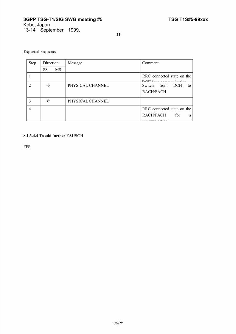
Expected sequence
Step Direction Message Comment
SS MS
1 RRC connected state on the
2 PHYSICAL CHANNEL Switch from DCH to
RACH/FACH
3 PHYSICAL CHANNEL
4 RRC connected state on the
RACH/FACH for a
8.1.3.4.4 To add further FAUSCH
FFS
3GPP
7/30/2019 T1S-SIG#51
http://slidepdf.com/reader/full/t1s-sig51 34/61
3GPP TSG-T1/SIG SWG meeting #5 TSG T1S#5-99xxxKobe, Japan13-14 September 1999,
34
8.1.3.5 RRC Connected Mode : Transport Channel Reconfiguration
8.1.3.5.1 Synchronised transport format set reconfiguration
8.1.3.5.1.1 Conformance requirement
・This procedure reconfigures parameters related to a transport channel such as the TFS. The procedure also
assigns a TFCS and may change physical channel parameters to reflect a reconfiguration of a transport channel
in use.
・A TRANSPORT CHANNEL RECONFIGURATION message is sent from the RRC layer in the network to its
peer entity. This message contains the new transport format set, a new transport format combination Set and
may include physical channel parameters, i.e. new parameters for L1 , MAC and a activation time. When this
message is received in the UE a reconfiguration of L1 and MAC is done.
・Finally a TRANSPORT CHANNEL RECONFIGURATION COMPLETE message is returned to the network.
(This case is synchronised transport channel format set reconfiguration.
Reference
(GPP TS 25.331 clause 8.3.2
8.1.3.5.1.2 Test purpose
To confirm that the UE switches to another physical channel with a different spreading factor and TFS when it
receives a TRANSPORT CHANNEL RECONFIGURATION message from the UTRAN and continues the
communication on the DCH.
8.1.3.5.1.3 Method of test
Initial Condition
System Simulator : 1cell
UE :RRC connected state on the DCH
Foreseen Final state of the UE
RRC Connected State on the DCH using a different spreading factor and TFS.
Test Procedure
( The UE establishes a radio access bearer of DCH for a communication. For the new configuration the SS sends
a TRANSPORT CHANNEL RECONFIGURATION message which contains the next used transport channel
and physical channel parameters ( e.g. a new TFS, TFCS ,spreading factor and activation time ( . The UE
reconfigures uplink L1 and L2 resources and starts to transmit data with a new configuration and switches to
the new configuration in downlink after activation time. Then the UE sends a TRANSPORT CHANNEL
RECONFIGURATION COMPLETE message to the SS and continues the communication on the DCH..
3GPP

7/30/2019 T1S-SIG#51
http://slidepdf.com/reader/full/t1s-sig51 35/61
3GPP TSG-T1/SIG SWG meeting #5 TSG T1S#5-99xxxKobe, Japan13-14 September 1999,
35
Maximum duration of the test
FFS
Expected sequence
Step Direction Message Comment
SS MS
1 RRC connected state with
2 TRANSPORT CHANNEL
RECONFIGURATION
Replace from DCH to DCH
with different spreading
factor
3 TRANSPORT CHANNEL
4 Continue a communication
on the DCH
8.1.3.5.2 Unsynchronised transport format set reconfiguration
8.1.3.5.2.1 Conformance requirement
・This procedure reconfigures parameters related to a transport channel such as the TFS. The procedure also
assigns a TFCS and may change physical channel parameters to reflect a reconfiguration of a transport channel
in use.
・A TRANSPORT CHANNEL RECONFIGURATION message is sent from the RRC layer in the network to its
peer entity. This message contains the new transport format set, a new transport format combination Set and
may include physical channel parameters, i.e. new parameters for L1 , MAC. When this message is received in
the UE a reconfiguration of L1 and MAC is done.
・Finally a TRANSPORT CHANNEL RECONFIGURATION COMPLETE message is returned to the network.
(This case is unsynchronised transport channel format set reconfiguration.
Reference
3GPP TS 25.331 clause 8.3.2
8.1.3.5.2.2 Test purpose
FFS
8.1.3.5.2.3 Method of test
Initial Condition
FFS
3GPP

7/30/2019 T1S-SIG#51
http://slidepdf.com/reader/full/t1s-sig51 36/61
3GPP TSG-T1/SIG SWG meeting #5 TSG T1S#5-99xxxKobe, Japan13-14 September 1999,
36
Foreseen Final state of the UE
FFS
Test Procedure
FFS
Maximum duration of the test
FFS
Expected sequence
Step Direction Message Comment
SS MS
1
2
3
4
8.1.3.5.3 Pre-configuration of TFS/TFCS for a transport channel not yet in use
8.1.3.5.3.1 Conformance requirement
FFS
Reference
3GPP TS 25.331 clause 8.3.2
8.1.3.5.3.2 Test purpose
FFS
8.1.3.5.3.3 Method of test
Initial Condition
FFS
Foreseen Final state of the UE
FFS
Test Procedure
FFS
3GPP

7/30/2019 T1S-SIG#51
http://slidepdf.com/reader/full/t1s-sig51 37/61
3GPP TSG-T1/SIG SWG meeting #5 TSG T1S#5-99xxxKobe, Japan13-14 September 1999,
37
Maximum duration of the test
FFS
Expected sequence
Step Direction Message Comment
SS MS
1
2
3
4
3GPP

7/30/2019 T1S-SIG#51
http://slidepdf.com/reader/full/t1s-sig51 38/61
3GPP TSG-T1/SIG SWG meeting #5 TSG T1S#5-99xxxKobe, Japan13-14 September 1999,
38
8.1.3.6 RRC Connected Mode : Transport format combination Control
8.1.3.6.1 Conformance requirement
・This procedure is that the network controls which transport format combinations (within the transport format
combination set) can be used by the UE in the uplink.
・This procedure is initiated with a TRANSPORT FORMAT COMBINATION CONTROL message sent from
the network to the UE. This message defines the subset of the complete transport format combination set which
the UE is allowed to use, or in case of removing a temporary restriction, a TFCS which is identical to the
complete original set. The UE then reconfigures MAC which thereafter uses the new TFC set.
Reference
3GPP TS 25.331 clause 8.3.3
8.1.3.6.2 Test purpose
To confirm that the UE reconfigures the TFCS in the uplink to follow the TRANSPORT FORMAT
COMBINATION CONTROL message sent from the UTRAN.
8.1.3.6.3 Method of test
Initial Condition
System Simulator : 1cell
UE :RRC connected state on the DCH
Foreseen Final state of the UE
RRC Connected State on the DCH reconfigured the TFCS in the uplink.
Test Procedure
(The UE establishes a radio access bearer on the DCH for a communication. The SS sends a TRANSPORTFORMAT COMBINATION CONTROL message which contains the TFCS used in the uplink. The UE
reconfigures the TFCS, then continues the communication.
Maximum duration of the test
FFS
3GPP

7/30/2019 T1S-SIG#51
http://slidepdf.com/reader/full/t1s-sig51 39/61
3GPP TSG-T1/SIG SWG meeting #5 TSG T1S#5-99xxxKobe, Japan13-14 September 1999,
39
Expected sequence
Step Direction Message Comment
SS MS1 RRC connected state on the
2 TRANSPORT FORMAT Reconfigure the TFCS in the
uplink
3 Continue a communication
3GPP

7/30/2019 T1S-SIG#51
http://slidepdf.com/reader/full/t1s-sig51 40/61
3GPP TSG-T1/SIG SWG meeting #5 TSG T1S#5-99xxxKobe, Japan13-14 September 1999,
40
8.1.4 Mobility in connected mode
8.1.4.1 Soft Handover
8.1.4.1.1 Radio link addition
8.1.4.1.1.1 Conformance requirement
・Radio link addition is triggered in the network RRC layer. The NW RRC first configures the new radio link.
Transmission and reception begin immediately. The NW RRC then sends an ACTIVE SET UPDATE message
to the UE RRC. The UE RRC configures layer 1 to begin reception. After confirmation from the physical layer
in the UE an ACTIVE SET UPDATE COMPLETE message is sent to the NW RRC
Reference
3GPP TS 25.331 clause 8.3.5.1
3GPP TR 25.931 clause 9.12.1
8.1.4.1.1.2 Test purpose
To confirm that the UE continues to communicate with the UTRAN on both the additional radio link and an
already existing radio link after a radio link addition.
8.1.4.1.1.3 Method of test
Initial Condition
System Simulator : 1cell( No.1 cell)
UE :RRC connected state on the DCH in a No.1 cell
Foreseen Final state of the UE
The UE continues to communicate on both an added radio link and an already existing radio link
Test Procedure
( The UE establishes a radio access bearer on the DCH in No.1 cell. The SS starts to broadcast the BCCH and
configures the new radio link in No.2 cell. Then the SS sends to the UE an ACTIVE SET UPDATE message
which contains parameters of a new radio link (e.g. Update type :addition, Cell-id, DL scrambling code, DLchannelisation code, Power control information(on the existing radio link. When the UE receives this message,
the UE RRC configures layer 1 to begin reception. After confirmation from the physical layer, the UE sends an
ACTIVE SET UPDATE COMPLETE message to the SS. The UE continues to communicate with the SS on
the both radio links.
Maximum duration of the test
FFS
3GPP
7/30/2019 T1S-SIG#51
http://slidepdf.com/reader/full/t1s-sig51 41/61
3GPP TSG-T1/SIG SWG meeting #5 TSG T1S#5-99xxxKobe, Japan13-14 September 1999,
41
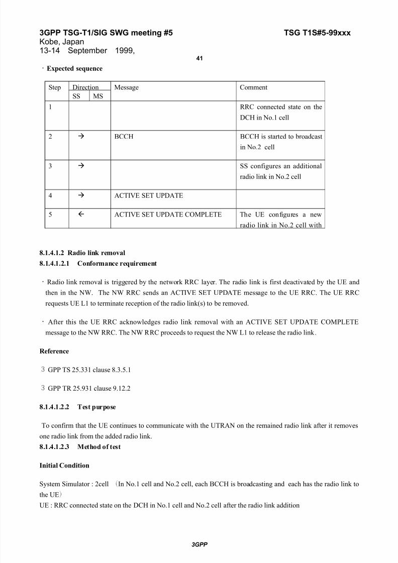
・Expected sequence
Step Direction Message Comment
SS MS1 RRC connected state on the
DCH in No.1 cell
2 BCCH BCCH is started to broadcast
in No.2 cell
3 SS configures an additional
radio link in No.2 cell
4 ACTIVE SET UPDATE
5 ACTIVE SET UPDATE COMPLETE The UE configures a new
radio link in No.2 cell with
8.1.4.1.2 Radio link removal
8.1.4.1.2.1 Conformance requirement
・Radio link removal is triggered by the network RRC layer. The radio link is first deactivated by the UE and
then in the NW. The NW RRC sends an ACTIVE SET UPDATE message to the UE RRC. The UE RRCrequests UE L1 to terminate reception of the radio link(s) to be removed.
・After this the UE RRC acknowledges radio link removal with an ACTIVE SET UPDATE COMPLETE
message to the NW RRC. The NW RRC proceeds to request the NW L1 to release the radio link .
Reference
3GPP TS 25.331 clause 8.3.5.1
3GPP TR 25.931 clause 9.12.2
8.1.4.1.2.2 Test purpose
To confirm that the UE continues to communicate with the UTRAN on the remained radio link after it removes
one radio link from the added radio link.
8.1.4.1.2.3 Method of test
Initial Condition
System Simulator : 2cell (In No.1 cell and No.2 cell, each BCCH is broadcasting and each has the radio link to
the UE)UE : RRC connected state on the DCH in No.1 cell and No.2 cell after the radio link addition
3GPP

7/30/2019 T1S-SIG#51
http://slidepdf.com/reader/full/t1s-sig51 42/61
3GPP TSG-T1/SIG SWG meeting #5 TSG T1S#5-99xxxKobe, Japan13-14 September 1999,
42
Foreseen Final state of the UE
The UE continues to communicate on the remained radio link in No.2 cell after the removal of the old radio link
in No.1 cell.
Test Procedure
・The UE establishes a radio access bearer on the DCH in No.1 and No.2 cells after radio link addition. The SS
sends to the UE an ACTIVE SET UPDATE message which contains parameters of a radio link to be
removed(e.g. Update type: deletion, Cell-id(. When the UE receives this message, the UE RRC request UE L1
to terminate reception of the radio link. Then the UE sends an ACTIVE SET UPDATE COMPLETE message
to the SS( The UE continues to communicate with the SS on the remained radio link.
Maximum duration of the test
FFS
Expected sequence
Step Direction Message Comment
SS MS
1 RRC connected state on the
DCH in No.1 and No.2 cell
2
ACTIVE SET UPDATE Deletion cell-Id is No.13 ACTIVE SET UPDATE COMPLETE The UE removes a radio link
in No.2 cell and continues to
communicate on the
remaining radio link
8.1.4.1.3 Combined radio link addition and removal
8.1.4.1.3.1 Conformance requirement
・When radio links are to be replaced, the NW RRC first configures the NW L1 to activate the radio link(s) that
are being added. The NW RRC then sends an ACTIVE SET UPDATE message to the UE RRC, which
configures the UE L1 to terminate reception on the removed radio link(s) and begin reception on the added
radio link(s).
・The UE RRC acknowledges the replacement with an ACTIVE SET UPDATE COMPLETE message.
Reference
3GPP TS 25.331 clause 8.3.5.1
3GPP TR 25.931 clause 9.12.3
3GPP

7/30/2019 T1S-SIG#51
http://slidepdf.com/reader/full/t1s-sig51 43/61
3GPP TSG-T1/SIG SWG meeting #5 TSG T1S#5-99xxxKobe, Japan13-14 September 1999,
43
8.1.4.1.3.2 Test purpose
To confirm that the UE continues to communicate with the UTRAN on the added radio link and removes already
existing radio link.
8.1.4.1.2.3 Method of test
Initial Condition
System Simulator : 1cell( No.1 cell)
UE :RRC connected state on the DCH in No.1 cell [Active set is not full.]
Foreseen Final state of the UE
The UE continues to communicate on the added radio link.
Test Procedure
( The UE establishes a radio access bearer on the DCH in No.1 cell. The SS starts to broadcast the BCCH and
configures the new radio link in No.2 cell. Then the SS sends to the UE an ACTIVE SET UPDATE message
which contains parameters (e.g. Update type : addition and deletion, Cell-id, DL scrambling code, DL
channelisation code, Power control information(on the existing radio link. When the UE receives this message,
the UE RRC configures layer 1 to begin reception. After confirmation from the physical layer, the UE sends an
ACTIVE SET UPDATE COMPLETE message to the SS and removes an already existing radio link in No.1
cell. The UE continues to communicate with the SS on the added radio link.
Maximum duration of the test
FFS
Expected sequence
Step Direction Message Comment
SS MS
1 RRC connected state on theDCH in No.1 cell
2 BCCH BCCH is started to broadcast
3 SS configures an additional
radio link in No.2 cell
4 ACTIVE SET UPDATE Addition and deletion
5 ACTIVE SET UPDATE COMPLETE The UE configures a new
radio link in No.2 cell and
3GPP
7/30/2019 T1S-SIG#51
http://slidepdf.com/reader/full/t1s-sig51 44/61
3GPP TSG-T1/SIG SWG meeting #5 TSG T1S#5-99xxxKobe, Japan13-14 September 1999,
44
8.1.4.2 Hard Handover
8.1.4.2.1 Inter frequency hard handover
8.1.4.2.1.1 Conformance requirement
・The NW RRC sends the UE RRC a HANDOVER COMMAND message. The message indicates the radio
resources that should be used for the new radio link. The UE RRC configures the UE L1 to terminate reception
on the old radio link and begin reception on the new radio link.
・After the UE L1 has achieved downlink synchronisation on the new frequency, a L2 link is established and the
UE RRC sends a HANDOVER COMPLETE message to the NW RRC.
Reference
3GPP TS 25.331 clause 8.3.5.2
8.1.4.2.1.2 Test purpose
To confirm that the UE continues to communicate with the UTRAN on the new frequency after the hard
handover.
8.1.4.1.2.3 Method of test
Initial Condition
System Simulator : 1cell( No.1 cell)
UE :RRC connected state on DCH in No.1 cell
Foreseen Final state of the UE
The UE continues to communicate on the new frequency
Test Procedure
・The UE establishes a radio access bearer on DCH in No.1 cell. The SS starts to broadcast the BCCH in No.2
cell and configures the new radio link. Then the SS sends to the UE a HANDOVER COMMAND message
which contains parameters(e.g. frequency( of a new radio link on the existing radio link. Then after the UE L1
achieves downlink synchronisation on the new frequency, a L2 link is established and the UE RRC sends a
HANDOVER COMPLETE message to the SS RRC. The UE continues to communicate with the SS on the
new radio link in No.2 cell.
Maximum duration of the test
FFS
3GPP

7/30/2019 T1S-SIG#51
http://slidepdf.com/reader/full/t1s-sig51 45/61
3GPP TSG-T1/SIG SWG meeting #5 TSG T1S#5-99xxxKobe, Japan13-14 September 1999,
45
・Expected sequence
Step Direction Message Comment
SS MS1 RRC connected state on
DCH in No.1 cell
2 BCCH BCCH is started to broadcast
in No.2 cell
3 SS configures a new radio
link in No.2 cell
4 HANDOVER COMMAND
5 HANDOVER COMPLETE The UE configures a new
radio link in No.2 cell with
different frequeny from No.1
cell and terminates reception
on the old radio link
8.1.4.2.2 Inter system hard handover(GSM/BSS to UTRAN)FFS
8.1.4.2.3 Inter system hard handover(UTRAN to GSM/BSS)
FFS
8.1.4.3 Cell Reselection
8.1.4.3.1 Inter system(GSM to UTRAN )
FFS
8.1.4.3.2 Inter system(UTRAN to GSM/BSS)
FFS
3GPP

7/30/2019 T1S-SIG#51
http://slidepdf.com/reader/full/t1s-sig51 46/61
3GPP TSG-T1/SIG SWG meeting #5 TSG T1S#5-99xxxKobe, Japan13-14 September 1999,
46
8.1.4.4 URA Update
8.1.4.4.1.1 Conformance requirement
・The URA update procedure is normally used by the UE to inform the UTRAN that the UE has switched to a
new URA. In this case the procedure is triggered after change of cell and after the UE has decoded from the
BCCH the URA identifiers valid in that cell. The procedure can also be triggered by expiry of a URA update
periodicity timer in the UE.
・To perform the URA update procedure the UE shall send a URA UPDATE message to the UTRAN. Upon
reception of the message the UTRAN registers the change of URA, and sends a URA UPDATE CONFIRM
message to the UE. The URA UPDATE CONFIRM message may include a new C-RNTI and/or S-RNTI plus
SRNC identity.
Reference
3GPP TS 25.331 clause 8.3.7
3GPP TS 25.303 clause 5
3GPP TR 25.931 clause 9.14
8.1.4.4.1.2 Test purpose
To confirm that the UE executes a URA update procedure to update UTRAN registration area after change of cell
when RRC connection exists and the position of the UE is known on URA level in the UTRAN.
8.1.4.4.2.3 Method of test
Initial Condition
System Simulator : 1cell(Broadcasting BCCH contains a URA identity which is x)
UE : RRC connection exists and the position is known on URA level in the SS(URA identity is x)
Foreseen Final state of the UE
URA connected state with a new URA information after the URA update procedure
Test Procedure
The UE is in the URA connected state and it has URA identity x. The SS starts to broadcast BCCH which
contains a different URA identity y and stop sending BCCH which contains URA identity x. When the UE finds
changing a cell and URA identity, it enters the cell connected state and sends a URA UPDATE message to the
SS. After receiving this message the SS sends a URA UPDATE COMPLETE message to the UE. Then the UE’s
state is changed back to URA connected.
[ Editor’s note : This procedure is done after handover procedure. ]
Maximum duration of the test
FFS
3GPP

7/30/2019 T1S-SIG#51
http://slidepdf.com/reader/full/t1s-sig51 47/61
3GPP TSG-T1/SIG SWG meeting #5 TSG T1S#5-99xxxKobe, Japan13-14 September 1999,
47
Expected sequence
Step Direction Message Comment
SS MS
1 URA connected state with
2 BCCH BCCH with URA identity y
is started to send and BCCH
with URA identity x is
3 URA UPDATE The UE enters the cell
connected state and sends
4 URA UPDATE CONFIRM After receiving this message
8.1.4.5 Cell Update
8.1.4.5.1.1 Conformance requirement
・The cell update procedure is normally used by the UE to inform the UTRAN that the UE has switched to a new
cell. In this case the procedure is a forward handover procedure, and is triggered after change of cell and after
the UE has read information broadcasted by UTRAN. The procedure can also be triggered by expiry of a cell
update periodicity timer in the UE or in cases when the UE requests a new C-RNTI..
・To perform the cell update procedure the UE shall send a CELL UPDATE message to the UTRAN. Upon
reception of the message the UTRAN sends a CELL UPDATE CONFIRM message to the UE. The URA
UPDATE CONFIRM message may include a new C-RNTI and/or S-RNTI plus SRNC identity.
Reference
3GPP TS 25.331 clause 8.3.8
3GPP TS 25.303 clause 5
3GPP TR 25.931 clause 9.13.2
8.1.4.5.1.2 Test purpose
To confirm that the UE executes a cell update procedure after change of cell(cell reselection) when an RRC
connection exists and the position of the UE is known on cell level in the UTRAN.
8.1.4.5.2.3 Method of test
Initial Condition
System Simulator : 1cell(Broadcasting BCCH contains cell-Id x)
UE : RRC connection exists and the position is known on cell level in the SS
3GPP

7/30/2019 T1S-SIG#51
http://slidepdf.com/reader/full/t1s-sig51 48/61
3GPP TSG-T1/SIG SWG meeting #5 TSG T1S#5-99xxxKobe, Japan13-14 September 1999,
48
Foreseen Final state of the UE
Cell connected state with a new C-RNTI and/or S-RNTI plus SRNC identity.
Test Procedure
The UE is in the cell connected state and it has C-RNTI and/or S-RNTI plus SRNC identity. The SS starts to
broadcast BCCH which contains cell-id y and stop sending BCCH which contains cell-id x. When the UE finds
changing a cell, it sends a CELL UPDATE message to the SS. After receiving this message the SS sends a URA
UPDATE COMPLETE message which contains a new C-RNTI and/or S-RNTI plus SRNC identity to the UE..
Maximum duration of the test
FFS
Expected sequence
Step Direction Message Comment
SS MS
1 Cell connected state
2 BCCH BCCH with cell-id y is
started to send and BCCH
with cell-id x is stopped
3 CELL UPDATE
8.1.4.6 RNTI reallocation
8.1.4.6.1.1 Conformance requirement
・This procedure is used by the network to assign new RNTI information to a UE. It is initiated by the UTRAN
by the sending of an RNTI REALLOCATION message which contains new S-RNTI and SRNC identity;
and/or a new C-RNTI. Then the UE starts to use the new identities and returns an RNTI REALLOCATION
COMPLETE message to the UTRAN.
Reference
3GPP TS 25.331 clause 8.3.9
8.1.4.6.1.2 Test purpose
To confirm that the UE starts to use the new identities after receiving an RNTI REALLOCATION message from
the UTRAN.
8.1.4.6.2.3 Method of test
3GPP

7/30/2019 T1S-SIG#51
http://slidepdf.com/reader/full/t1s-sig51 49/61
3GPP TSG-T1/SIG SWG meeting #5 TSG T1S#5-99xxxKobe, Japan13-14 September 1999,
49
Initial Condition
System Simulator : 1cell
UE : RRC connection exists and the position is known on cell level in the SS
Foreseen Final state of the UE
Cell connected state with new C-RNTI and/or S-RNTI plus SRNC identity.
Test Procedure
When the UE is in the cell connected state and it has C-RNTI and/or S-RNTI plus SRNC identity,the SS sends
an RNTI REALLOCATION message which contains new C-RNTI and/or S-RNTI plus SRNC identity to the UE.
Then the UE sends an RNTI REALLOCATION COMPLETE message as confirmation.
Maximum duration of the test
FFS
Expected sequence
Step Direction Message Comment
SS MS
1 Cell connected state
3 RNTI REALLOCATION COMPLETE
3GPP
7/30/2019 T1S-SIG#51
http://slidepdf.com/reader/full/t1s-sig51 50/61
3GPP TSG-T1/SIG SWG meeting #5 TSG T1S#5-99xxxKobe, Japan13-14 September 1999,
50
8.1.5 Others in connected mode
8.1.5.1 Core network originating paging
8.1.5.1.1 UTRAN coordinated paging using DCCH8.1.5.1.1.1 Conformance requirement
・UTRAN co-ordinates, UE is on the DCCH (PAGING TYPE 2 message is used) when the UE is in connected mode.
・ This procedure enables the CN to request paging of a UE. Since the UE can be reached on the DCCH,
the RRC layer formats a PAGING TYPE 2 message containing the UE paging identity and the NAS
information, and the message is transmitted directly to the UE using unacknowledged data transfer.
Reference
3GPP TS 25.331 clause 8.3.6.13GPP TS 25.303 clause 7.5.1
8.1.5.1.1.2 Test purpose
To confirm that the UE can respond to a PAGING TYPE 2 message which contains its identity and the NAS
information when the UE is in connected mode on DCCH.
8.1.5.1.1.3 Method of test
Initial Condition
System Simulator : 1 cell
UE : RRC connected state on DCCH
Foreseen Final state of the UE
The UE responds to the SS
Test Procedure
・The UE is in connected mode on the DCCH. The SS sends a PAGING TYPE 2 message containing its identity
and the NAS information on the DCCH to the UE. The UE responds to the SS to do appropriately for it.
Maximum duration of the test
FFS
3GPP

7/30/2019 T1S-SIG#51
http://slidepdf.com/reader/full/t1s-sig51 51/61
3GPP TSG-T1/SIG SWG meeting #5 TSG T1S#5-99xxxKobe, Japan13-14 September 1999,
51
Expected sequence
Step Direction Message Comment
SS MS1 RRC connected state on the
2 PAGING TYPE 2 Contain its identity and the
3 Appropriate action to the
paging
3GPP

7/30/2019 T1S-SIG#51
http://slidepdf.com/reader/full/t1s-sig51 52/61
3GPP TSG-T1/SIG SWG meeting #5 TSG T1S#5-99xxxKobe, Japan13-14 September 1999,
52
8.1.5.1.2 UTRAN coordinated paging using PCCH
FFS
8.1.5.1.3 UE coordinated pagingFFS
8.1.5.2 UTRAN originated paging
8.1.5.2.1 Conformance requirement
・The RRC layer in the network can use this procedure to trigger a switch from PCH or URA connected state to
RACH/FACH or RACH+FAUSCH/FACH state. A PAGING TYPE 1 message, containing the S-RNTI and
SRNC identity is sent on the PCCH.
・ In the UE, the RRC layer continuously monitors the paging group on the PCH and compares the UE identities
in the received paging messages with its own identities. When a match occurs, the RRC layer uses the cell
update procedure to acknowledge the reception of paging and optionally obtain a new C-RNTI.
Reference
3GPP TS 25.331 clause 8.3.6.2
3GPP TS 25.303 clause 7.6
8.1.5.2.2 Test purpose
To confirm that the its RRC layer changes state to RACH/FACH substate within the the cell connected mode
when the UE receives a PAGING TYPE 1 message which contains the S-RNTI and SRNC identity.
8.1.5.2.3 Method of test
Initial Condition
System Simulator : 1 cell
UE : The PCH substate of cell connected state
Foreseen Final state of the UE
The UE changes to RACH/FACH substate within the cell connected mode.
Test Procedure
( The UE is in the PCH substate of cell connected state. The SS sends a PAGING TYPE 1 message which
contains the S-RNTI and SRNC-ID to the UE. Then the UE changes state to the RACH/FACH substate and the
cell update procedure is done.
Maximum duration of the test
FFS
3GPP

7/30/2019 T1S-SIG#51
http://slidepdf.com/reader/full/t1s-sig51 53/61
3GPP TSG-T1/SIG SWG meeting #5 TSG T1S#5-99xxxKobe, Japan13-14 September 1999,
53
Expected sequence
Step Direction Message Comment
SS MS
1 PCH substate of cell
2 PAGING TYPE 1 Containing S-RNTI and
3 RACH/FACH substate of
4 CELL UPDATE
3GPP

7/30/2019 T1S-SIG#51
http://slidepdf.com/reader/full/t1s-sig51 54/61
3GPP TSG-T1/SIG SWG meeting #5 TSG T1S#5-99xxxKobe, Japan13-14 September 1999,
54
8.1.5.3 Measurement Control and Report
8.1.5.3.1 Conformance requirement
・This procedure is initiated from the UTRAN side to control a measurement in a specific UE. The UTRAN
sends a MEASUREMENT CONTROL message to the UE on the DCCH. The message contains the information
that controls the UE measurement.
・The Measurement Report procedure is initiated from the UE side when the reporting criteria are met. The
message is sent using either acknowledged or unacknowledged data transfer on the DCCH. The UE sends a
MEASUREMENT REPORT message to the UTRAN that contains the measurement identity number and the
measurement results of the mandatory and optional report quantities that were defined in the corresponding
MEASUREMENT CONTROL.
Reference
3GPP TS25.331 clause 8.3.7.1 clause 8.3.7.2 clause 15.1
8.1.5.3.2 Test purpose
To confirm that the UE sends a MEASUREMENT REPORT message which contains the measurement identity
number and the measurement results for the items defined in the MEASUREMENT CONTROL message sent
from the UTRAN.
8.1.5.3.3 Method of test
Initial Condition
System Simulator : 1cell
UE : RRC connected state on the DCCH
Foreseen Final state of the UE
RRC Connected State after sending a MEASUREMENT REPORT message
Test Procedure
The UE is in the RRC connected state on the DCCH. The SS sends a MEASUREMEN CONTROL message
which contains parameters (e.g. Measurement type: intra-frequency measurements, measurement reporting mode:
unacknowledged and event trigger, measurement object: intra-frequency cell information, measurement quantity:
primary CCPCH RX E0/I0 , reporting quantity: primary CCPCH RX E0/I0 ,measurement reporting criteria: event
id 1a and a reporting range). The SS starts to send a BCCH in the another cell and its tx power is within the
reporting range. Then the UE finds that the another BCCH level enters the reporting range and it sends a
MEASUREMENT REPORT message to the SS.
3GPP
7/30/2019 T1S-SIG#51
http://slidepdf.com/reader/full/t1s-sig51 55/61
3GPP TSG-T1/SIG SWG meeting #5 TSG T1S#5-99xxxKobe, Japan13-14 September 1999,
55
Maximum duration of the test
FFS
3GPP

7/30/2019 T1S-SIG#51
http://slidepdf.com/reader/full/t1s-sig51 56/61
3GPP TSG-T1/SIG SWG meeting #5 TSG T1S#5-99xxxKobe, Japan13-14 September 1999,
56
Expected sequence
Step Direction Message Comment
SS MS
1 RRC connected state on
2 MEASUREMENT CONTROL Measurement type: intra-
frequency measurements,
measurement reporting
mode: unacknowledged and
event trigger, measurement
object: intra-frequency cellinformation, measurement
quantity: primary CCPCH
RX E0/I0 , reporting
quantity: primary CCPCH
RX E0/I0 ,measurement
reporting criteria: event id 1a
and a reporting range
3 BCCH Its level is within the
reporting range in another
4 MEASUREMENT REPORT
8.1.5.4 System Information in RRC connected mode
FFS
8.1.5.5 Direct Transfer
8.1.5.5.1 Conformance requirement
・The direct transfer procedure is used to carry all higher layer (NAS) messages over the radio interface. The
DIRECT TRANSFER message includes the higher layer (NAS) message as payload and a CN domain identifier
of the destination (in uplink) or originating (in downlink) core network node.
・The DIRECT TRANSFER message is used both in uplink and in downlink.
・Upon reception of the DIRECT TRANSFER message the higher layer PDU is routed – using the CN domain
identifier parameter – in UE side to correct higher layer entity and in UTRAN side to correct CN domain.
3GPP
7/30/2019 T1S-SIG#51
http://slidepdf.com/reader/full/t1s-sig51 57/61
3GPP TSG-T1/SIG SWG meeting #5 TSG T1S#5-99xxxKobe, Japan13-14 September 1999,
57
Reference
3GPP TS 25.331 clause 8.3.8.3
3GPP

7/30/2019 T1S-SIG#51
http://slidepdf.com/reader/full/t1s-sig51 58/61
3GPP TSG-T1/SIG SWG meeting #5 TSG T1S#5-99xxxKobe, Japan13-14 September 1999,
58
8.1.5.5.2 Test purpose
To confirm that the UE sends a DIRECT TRANSFER message which contains NAS message on DCCH when a
data is requested from NAS, and the UE routes to appropriate NAS entity when it receives a DIRECT
TRANSFER message.
8.1.5.5.3 Method of test
Initial Condition
System Simulator : 1cell
UE : RRC connected state on the DCCH
Foreseen Final state of the UE
RRC Connected State
Test Procedure
The UE is in the RRC connected state on the DCCH. The SS sends a DIRECT TRANSFER message which the
UE’s NAS entity needs to respond to the SS’s same entity. Then the UE sends a DIRECT TRANSFER message to
respond to this message.
Maximum duration of the test
FFS
Expected sequence
Step Direction Message Comment
SS MS
1 RRC connected state on
2 DIRECT TRANSFER
3
DIRECT TRANSFER
3GPP

7/30/2019 T1S-SIG#51
http://slidepdf.com/reader/full/t1s-sig51 59/61
3GPP TSG-T1/SIG SWG meeting #5 TSG T1S#5-99xxxKobe, Japan13-14 September 1999,
59
8.1.5.6 RRC Status Procedure
8.1.5.6.1 Conformance requirement
・When a UE has signaling connections to CN1 and CN2, the UE has to release one of them without releasingthe RRC connection after receiving an RRC STATUS message. The UE RRC informs the corresponding MM
entity of RRC connection release and sends a RRC STATUS ACK message to the UTRAN.
Reference
3GPP TS 25.331 clause 8.3.8.4
8.1.5.6.2 Test purpose
To confirm that the UE sends a RRC STATUS ACK message when a RRC STATUS message is received and the
signaling connection is released.
8.1.5.6.3 Method of test
Initial Condition
System Simulator : 2cell (different core network domain identities)
UE : RRC connected state on the DCCH and has two signaling connections to CN1 and CN2
Foreseen Final state of the UE
Only one RRC Connection
Test Procedure
FFS
Maximum duration of the test
FFS
Expected sequence
Step Direction Message Comment
SS MS
1 RRC connected state on
2 RRC STATUS
3 RRC STATUS ACK
3GPP

7/30/2019 T1S-SIG#51
http://slidepdf.com/reader/full/t1s-sig51 60/61
3GPP TSG-T1/SIG SWG meeting #5 TSG T1S#5-99xxxKobe, Japan13-14 September 1999,
60
8.1.5.7 UE Capability Enqiry
8.1.5.7.1 Conformance requirement
・To request the capability information such as updating of GSM capability , the UTRAN sends a UECAPABILITY ENQUIRY message to the UE.
Reference
3GPP TS 25.331 clause 8.3.8.5
8.1.5.7.2 Test purpose
To confirm that the UE follows a UE CAPABILITY ENQUIR message and its capability is changed.
8.1.5.7.3 Method of test
Initial Condition
System Simulator :
UE :
Foreseen Final state of the UE
FFS
Test Procedure
FFS
Maximum duration of the test
FFS
Expected sequence
Step Direction Message Comment
SS MS
1 RRC connected state on
2 UE CAPABILITY ENQUIRY
3
3GPP

7/30/2019 T1S-SIG#51
http://slidepdf.com/reader/full/t1s-sig51 61/61
3GPP TSG-T1/SIG SWG meeting #5 TSG T1S#5-99xxxKobe, Japan13-14 September 1999,
61
8.1.6 Ciphering
FFS