t2™ arthrodesis nailing system - surgery advisor · 3 introduction the t2™ nailing system...
TRANSCRIPT

1
T2™ Arthrodesis Nailing System
Operative Technique

2
Contributing Surgeon:
This publication sets forth detailed recommended procedures for using Stryker Trauma devices and instruments.
It offers guidance that you should heed, but, as with any such technical guide, each surgeon must consider the particular needs of each patient and make appropriate adjustments when and as required.
A workshop training is required prior to first surgery.
Stephen IncavoMD University of VermontDepartment of Orthopaedics & RehabilitationBurlington/Vermont, USA
Prof. Dr. Dr. Gunther O. HofmannChief of Surgical ServicesMedical Director of Halle Trauma CenterHalle, GermanyDirector of Trauma DepartmentFriedrich-Schiller-UniversityJena, Germany
Arthrodesis Nailing System
3
Introduction
The T2™ Nailing System represents the latest and most comprehensive development of the original intra-medullary principles presented by Prof. Gerhard Küntscher in 1940.
Stryker Trauma has now created a new generation locking nail system, bringing together all the capabilities and benefits of separate nailing systems to create a single, integrated surgical resource for fixation of long bones.
In addition to the T2™ Femoral, Tibial, and Humeral Nailing Systems, Stryker Trauma developed the T2™ Arthrodesis Nail to provide treatment of Knee Arthrodesis.
Through the development of a common, streamlined and intuitive surgical approach, both in principle and in detail, the T2™ Arthrodesis Nail offers significantly increased speed and functionality for the treatment of Knee Arthrodesis as well as simplifying the training requirements for all personnel involved.
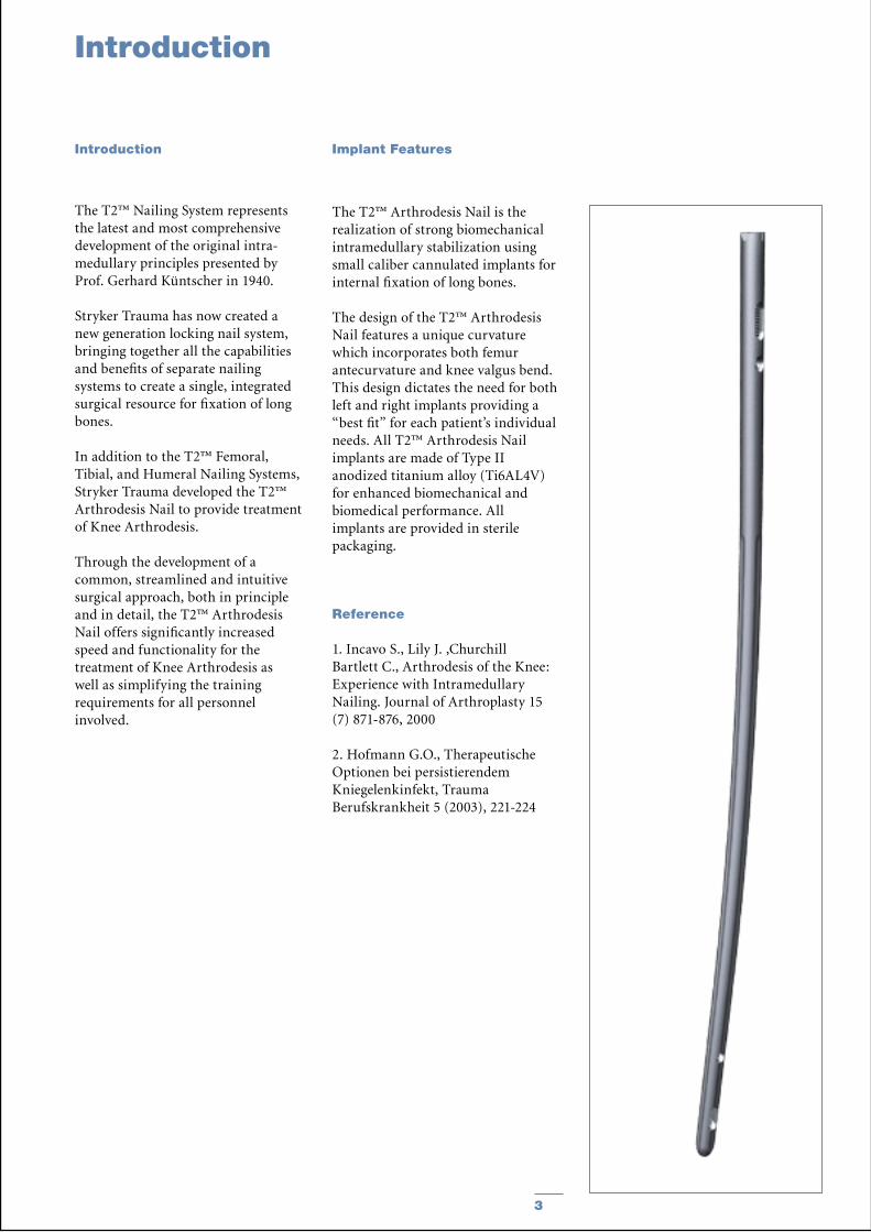
The T2™ Arthrodesis Nail is the realization of strong biomechanical intramedullary stabilization using small caliber cannulated implants for internal fixation of long bones.
The design of the T2™ Arthrodesis Nail features a unique curvature which incorporates both femur antecurvature and knee valgus bend. This design dictates the need for both left and right implants providing a “best fit” for each patient’s individual needs. All T2™ Arthrodesis Nail implants are made of Type II anodized titanium alloy (Ti6AL4V) for enhanced biomechanical and biomedical performance. All implants are provided in sterile packaging.
Reference
1. Incavo S., Lily J. ,Churchill Bartlett C., Arthrodesis of the Knee: Experience with Intramedullary Nailing. Journal of Arthroplasty 15 (7) 871-876, 2000
2. Hofmann G.O., Therapeutische Optionen bei persistierendem Kniegelenkinfekt, Trauma Berufskrankheit 5 (2003), 221-224
Introduction Implant Features

4
Technical Details
System Specifications
Two Nails, Left and Right
Diameters: 11.5 & 13mmLengths: 540 − 780mm in 40mm increments
Screws, End caps & Compression Screw (See Page 13 for complete description and catalog numbers.)
0mm
32.5mm35mm
45mm47.5mm
60mm
75 mm
35 mm
25 mm
0 mm
15mm5mm
10mm
Compression Range:Total Length of SlotLess Screw Diameter (−)
Maximum Movement of Screw

5
Operative Technique
The T2™ Arthrodesis Nail is inserted with the existing T2™ Femoral instrument set.
Note:The core instruments of the T2™ system provide the platform for all current and future Stryker Trauma Nailing Systems, thereby reducing complexity and inventory. Refer to the T2™ Femoral Nailing System Operative Technique (Cat. No. B1000004) and Tibial Nailing System Operative Technique (Cat. No. B1000005) for more detailed system protocols.
Indications for Knee Arthrodesis
• Aseptic failed total knee arthro-plasty with or without bone loss
• Failed external fixation, nonunions and malunions
• Periarticular fractures where repair is not possible
• Pathologic fractures, impending pathologic fractures, and tumor resections
• Pseudoarthrosis and correction osteotomy
• Ipsilateral femur fractures• Open and closed femoral fractures
Pre-operative Planing
An X-Ray Template (1806-0011) is available for pre-operative planning. Implant sizing is best determined using full length A/P and Lateral X-Rays of both the affected and contralateral legs. C.T. Scan for canal diameter and leg length may be useful. The knee should be placed in 5-10˚ of flexion and 5˚ valgus. The leg should be 1cm shorter than the opposite side. This position allows for more normal gait and foot clearance during walking. Ultimately, 1 cm of leg shortening is the goal, therefore in cases with more significant bone loss, additional flex-ion should be avoided to minimize additional shortening.
Patient positioning is surgeon dependent. The patient may be positioned supine (elevate the affected hip), lateral or semi-lateral on a radiolucent table.
Knee Incision
A vertical skin incision is made extending from the femoral condylar region to the tibial tubercule, followed by a parapatellar capsular incision. In cases with a previous incision, this one could be used. Knee arthroplasty instruments may be used to recut tibial and femoral surfaces.
Hip Incision and Entry Point
A skin incision is made beginning at the level of the Greater Trochanter extending proximal and slightly posterior, in line with the Gluteus Muscle, exposing the Piriformis Fossa. Alternatively, the Tip of the Greater Trochanter can be located by palpation, and a horizontal skin incision is made from the Greater Trochanter to the Iliac Crest. The medullary canal is opened with the curved awl (1806-0040), or with a 3×285mm K-Wire (1806-0050) and ø12mm Rigid Reamer (1806-2012) combination.
Alternatively, a minimal skin incision of the hip region can be made if the femoral canal is reamed in retrograde fashion from the knee joint. To accomplish this, the 3×1250mm Ball Tip Guide Wire (1806-1250S) is advanced from the distal femoral canal proximally to the greater trochanteric / piriformis fossa region.
Note:Avoid the femoral neck. The guide wire is then gently advanced through the cortex by gently tap-ping the strike plate on the Guide Wire Handle/Chuck assembly. Fluoroscopic visualization is neces-sary for this step. Once the guide wire exits the bone, it is retrieved through a small skin incision made over the tip of the guide wire.
Noting any deformity of the axis of the tibial shaft, and using either the Awl or Rigid Reamer over the K-Wire, open the anterior central medial aspect of the tibia using the tibial tubercle as a reference to the medullary canal.
Insert the 1250mm Ball Tip Guide Wire (1806-1250S) from the hip through the knee and advance into the tibial shaft to the depth at which you want the nail to end.
Note:Use image intensification (A/P and Lateral) for confirmation throughout each step.
Instrument Features Patient Positioning

6
Reaming
Operative Technique
Using a 885mm BixCut™ Modular Reamer Shaft (REF. Numbers on page 13), reaming is commenced in 0.5mm increments. Generally, the femur is reamed 1.5 – 2.0mm larger than the diameter of the nail selected, and the tibia is reamed line to line. The proximal end of the tibial shaft may be over-reamed if there is any question of final Femoral-Tibial alignment. Final determination of how much to ream either the femur or the tibia must be made by the surgeon based on many factors including bone quality and whether the nail will be cross-locked with screws distally in the tibia. As stated above, in some cases, surgeons may opt to use standard length Guide Wires and Reamers and ream the femur in retrograde fashion first and then the tibia separately.
Nail Assembly
The selected nail is assembled onto the Target Device (1806-1005) with the Femoral Holding Screw (1806-0165) (Fig. 1). Tighten the Nail Holding Screw with the Universal Socket Wrench (1806-0400) securely so that it does not loosen during nail insertion.
Note:Curvature of the nail must match the curvature of the femur and knee valgus.
Fig. 1
Nail Handle
Nailing Holding Screw
Strike Plate
Fixation Screw
Targeting Arm
K-Wire Hole
7
Nail Insertion Preparation
Fig. 5
Fig. 4
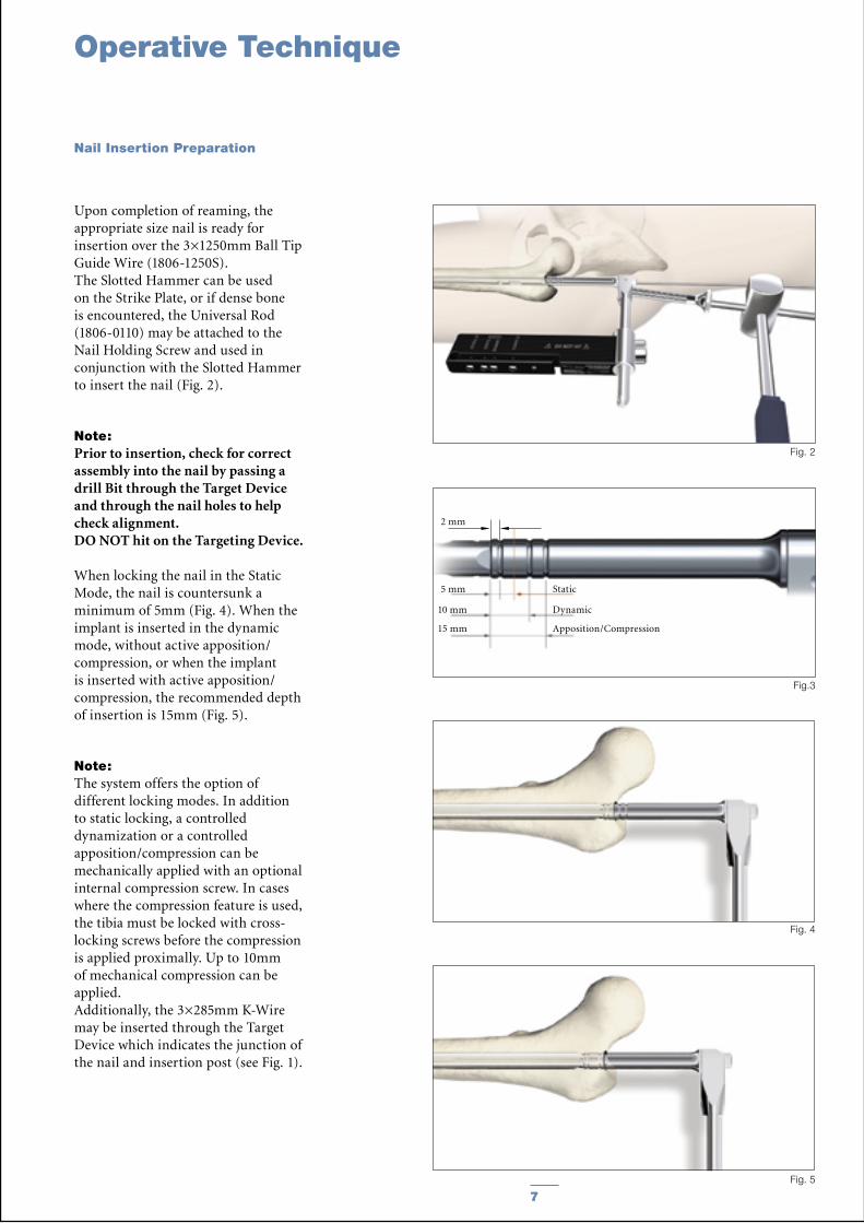
Upon completion of reaming, the appropriate size nail is ready for insertion over the 3×1250mm Ball Tip Guide Wire (1806-1250S).The Slotted Hammer can be used on the Strike Plate, or if dense bone is encountered, the Universal Rod (1806-0110) may be attached to the Nail Holding Screw and used in conjunction with the Slotted Hammer to insert the nail (Fig. 2).
Note:Prior to insertion, check for correct assembly into the nail by passing a drill Bit through the Target Device and through the nail holes to help check alignment. DO NOT hit on the Targeting Device.
When locking the nail in the Static Mode, the nail is countersunk a minimum of 5mm (Fig. 4). When the implant is inserted in the dynamic mode, without active apposition/compression, or when the implant is inserted with active apposition/compression, the recommended depth of insertion is 15mm (Fig. 5).
Note:The system offers the option of different locking modes. In addition to static locking, a controlled dynamization or a controlled apposition/compression can be mechanically applied with an optional internal compression screw. In cases where the compression feature is used, the tibia must be locked with cross-locking screws before the compression is applied proximally. Up to 10mm of mechanical compression can be applied.Additionally, the 3×285mm K-Wire may be inserted through the Target Device which indicates the junction of the nail and insertion post (see Fig. 1).
Fig. 2
Static
Dynamic
Apposition/Compression
2 mm
5 mm
10 mm
15 mm
Fig.3
Operative Technique

8
Operative Technique
To start the insertion of the nail, it is recommended that the Target Device is internally rotated to accommodate the individual patient’s anatomy (see Fig. 6, Position 1 for approximated example).
As the nail is passed down the femur towards the knee, a controlled external rotation of the Target Device is applied to better accommodate the unique dual curvature of the nail passing through the medullary canal (Fig. 7 position 2, 3, 4).
Note: The amount of internal rotation, and the timing of the external rotation is based on the individual patient’s anatomy and as such, the surgeon’s judgement. The final position of the Target Device must be directly lateral to the femur. In this final position, the hole pattern of the nail is properly lined up for screw insertion. Since every Arthrodesis case is different, the choice of whether to dynamize, actively compress, or statically lock the nail is up to the surgeon based on the individual patient’s indications.
Check the alignment of the leg in all axis with proper full length X-Rays and throughout the surgery (Fig. 8).
Note: As the nail is beginning to be introduced into the tibia, the final position of the foot must be determined with the foot being held in place accordingly as the nail is impacted to its final position. The amount of external rotation of the foot, generally 0 − 10 ,̊ is left to the surgeon’s discretion.
Fig. 6
Fig. 8
Position 2Position 3Position 4
Fig.7
Position 1
Position 1
Nail Insertion

9
In controlled Dynamic Mode, and/or controlled Apposition/Compression Mode, the dynamic hole is required (Fig. 9).4. Dynamic
In Advanced Locking Mode, the dynamic hole is required. After utilizing compression with the Compression Screw, the distal static hole is used. (Fig. 10).3. Static4. Dynamic
In Static Locking Mode, the distal static hole and the static position of the oblong hole are required (Fig. 10).2. Static3. Static
Note:Never use the most proximal static hole of the Target Device! There is no corresponding hole in the Arthrodesis Nail.
The Long Tissue Protection Sleeve (1806-0185) together with the Long Drill Sleeve (1806-0215) and the Long Trocar (1806-0315) is inserted into the Target Device by pressing the safety clip (Fig. 11). The mechanism will keep the sleeve in place and prevent it from falling out. It will also prevent the sleeve from sliding during screw measurement. To release the Tissue Protection Sleeve, the safety clip must be pressed again.
Note:Remove the Guide Wire prior to drilling and inserting the Locking Screws.
Fig. 11
Fig.9
3
4
4
Fig.10
2
Operative Technique
locked
released
Guided Locking Mode (via Target Device)
10
50mm
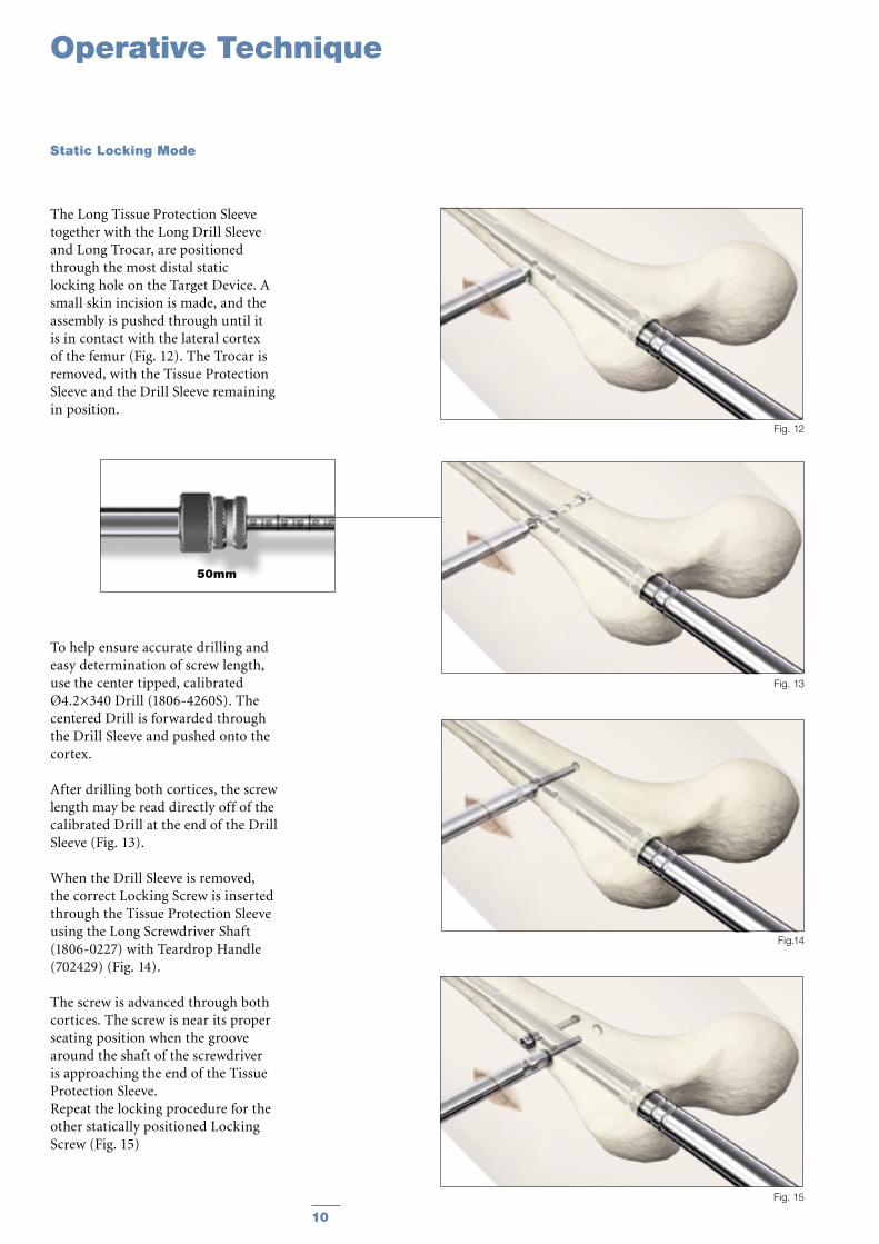
The Long Tissue Protection Sleeve together with the Long Drill Sleeve and Long Trocar, are positioned through the most distal static locking hole on the Target Device. A small skin incision is made, and the assembly is pushed through until it is in contact with the lateral cortex of the femur (Fig. 12). The Trocar is removed, with the Tissue Protection Sleeve and the Drill Sleeve remaining in position.
To help ensure accurate drilling and easy determination of screw length, use the center tipped, calibrated Ø4.2×340 Drill (1806-4260S). The centered Drill is forwarded through the Drill Sleeve and pushed onto the cortex.
After drilling both cortices, the screw length may be read directly off of the calibrated Drill at the end of the Drill Sleeve (Fig. 13).
When the Drill Sleeve is removed, the correct Locking Screw is inserted through the Tissue Protection Sleeve using the Long Screwdriver Shaft (1806-0227) with Teardrop Handle (702429) (Fig. 14).
The screw is advanced through both cortices. The screw is near its proper seating position when the groove around the shaft of the screwdriver is approaching the end of the Tissue Protection Sleeve.Repeat the locking procedure for the other statically positioned Locking Screw (Fig. 15)
Fig. 15
Fig. 12
Fig.14
Fig. 13
Operative Technique
Static Locking Mode

11
Note:Distal freehand static locking with at least two Fully Threaded Locking Screws must be performed prior to applying active, controlled apposition/compression to the fusion site.
If active apposition/compression is required, a Partially Threaded Locking Screw (Shaft Screw) is inserted via the Target Device in the dynamic position of the oblong hole. This will allow for a maximum of 10mm of active, controlled apposition/compression. In order to insert the Shaft Screw, drill both cortices with the Ø4.2×340 Drill (1806-4260S). Next, drill the near cortex, ONLY, with the Ø5.0×230mm Drill (1806-5000S).
After the opposite cortex is drilled with the Ø4.2×340mm Drill, the correct screw length can be read directly off of the calibrated Drill at the end of the Drill Sleeve.
After the Shaft Screw is inserted, the Nail Holding Screw securing the nail to the insertion post is removed, leaving the insertion post intact with the nail (Fig. 16). This will act as a guide for the Compression Screw. The Compression Screw is inserted with the Screwdriver Shaft (1806-0227) assembled on the Teardrop Handle through the insertion post (Fig. 17 & 18).
As the Compression Screw is advanced against the 5mm Partially Threaded Screw (Shaft Screw), active apposition/compression is applied at the knee site.
Note:Apposition/compression should be carried out under X-Ray control.
Fig. 17
Fig.16
Fig. 18
Operative Technique
Apposition/Compression Locking Mode

12
Freehand Distal Locking
Operative Technique
Green Ring
The freehand technique is used to insert Locking Screws into the M/L holes in the nail. Rotational alignment must be checked prior to locking the nail statically. Multiple locking techniques and radiolucent drill devices are available for freehand locking. The critical step with any freehand locking technique is to visualize a perfectly round locking hole with the C-Arm.
The center-tipped Ø4.2×180 Drill (1806-4270S) is held at an oblique angle to the center of the locking hole (Fig. 19). Upon X-Ray verification, the Drill is placed perpendicular to the nail and drilled through the medial cortex. Confirm in both the A/P and M/L planes by X-Ray that the Drill passes through the hole in the nail.
After drilling both cortices the screw length may be read directly off of the calibrated Short Screw Scale (1806-0360) at the green ring on the center-tipped Drill (Fig. 20 & 21). This short screw scale is part of the T2 Tibial Instrument Set, or T2 Femur/Tibia Combined Instrument Set (1806-6020).
Note:The position of the end of the drill is equal to the end of the screw as they relate to the far cortex.
Routine Locking Screw insertion is employed with the assembled Screwdriver Shaft and Teardrop Handle.
Note:The Screwdriver Shaft may be used in conjunction with the Long Screw Capture Sleeve (1806-0240).
Fig. 19
Fig. 20
Fig. 21
20mm
13
Ordering Information - Implants
Note:Federal law (U.S.A) restricts this device to sale by or on the order of a licensed physician.
REF Diameter Length mm mm
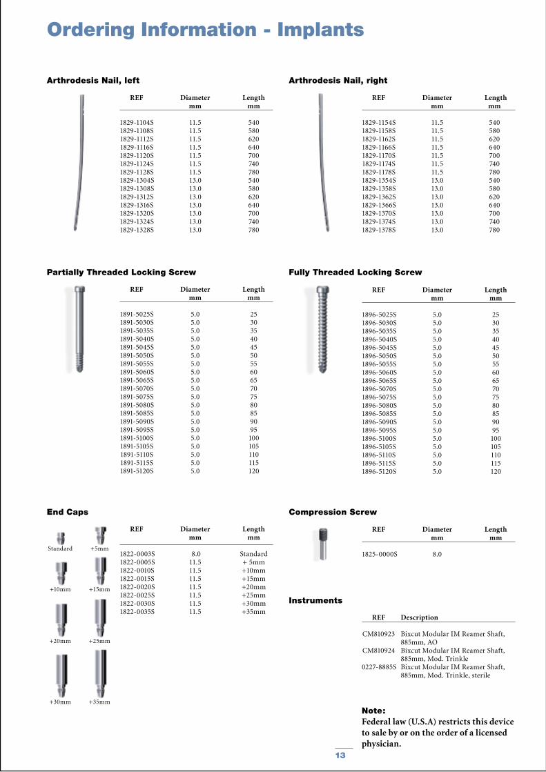
1829-1104S 11.5 540 1829-1108S 11.5 580 1829-1112S 11.5 620 1829-1116S 11.5 640 1829-1120S 11.5 700 1829-1124S 11.5 740 1829-1128S 11.5 780 1829-1304S 13.0 540 1829-1308S 13.0 580 1829-1312S 13.0 620 1829-1316S 13.0 640 1829-1320S 13.0 700 1829-1324S 13.0 740 1829-1328S 13.0 780
Arthrodesis Nail, left
REF Diameter Length mm mm
1829-1154S 11.5 540 1829-1158S 11.5 580 1829-1162S 11.5 620 1829-1166S 11.5 640 1829-1170S 11.5 700 1829-1174S 11.5 740 1829-1178S 11.5 780 1829-1354S 13.0 540 1829-1358S 13.0 580 1829-1362S 13.0 620 1829-1366S 13.0 640 1829-1370S 13.0 700 1829-1374S 13.0 740 1829-1378S 13.0 780
Arthrodesis Nail, right
Compression Screw
Partially Threaded Locking Screw
REF Diameter Length mm mm
1891-5025S 5.0 25 1891-5030S 5.0 30 1891-5035S 5.0 35 1891-5040S 5.0 40 1891-5045S 5.0 45 1891-5050S 5.0 50 1891-5055S 5.0 55 1891-5060S 5.0 60 1891-5065S 5.0 65 1891-5070S 5.0 70 1891-5075S 5.0 75 1891-5080S 5.0 80 1891-5085S 5.0 85 1891-5090S 5.0 90 1891-5095S 5.0 95 1891-5100S 5.0 100 1891-5105S 5.0 105 1891-5110S 5.0 110 1891-5115S 5.0 115 1891-5120S 5.0 120
+5mm
+10mm +15mm
Standard
REF Diameter Length mm mm
1822-0003S 8.0 Standard1822-0005S 11.5 + 5mm1822-0010S 11.5 +10mm1822-0015S 11.5 +15mm1822-0020S 11.5 +20mm1822-0025S 11.5 +25mm1822-0030S 11.5 +30mm1822-0035S 11.5 +35mm
End Caps
+20mm +25mm
+30mm +35mm
Fully Threaded Locking Screw
REF Diameter Length mm mm
1896-5025S 5.0 25 1896-5030S 5.0 30 1896-5035S 5.0 35 1896-5040S 5.0 40 1896-5045S 5.0 45 1896-5050S 5.0 50 1896-5055S 5.0 55 1896-5060S 5.0 60 1896-5065S 5.0 65 1896-5070S 5.0 70 1896-5075S 5.0 75 1896-5080S 5.0 80 1896-5085S 5.0 85 1896-5090S 5.0 90 1896-5095S 5.0 95 1896-5100S 5.0 100 1896-5105S 5.0 105 1896-5110S 5.0 110 1896-5115S 5.0 115 1896-5120S 5.0 120
REF Diameter Length mm mm
1825-0000S 8.0
Instruments
REF Description
CM810923 Bixcut Modular IM Reamer Shaft, 885mm, AO CM810924 Bixcut Modular IM Reamer Shaft, 885mm, Mod. Trinkle 0227-8885S Bixcut Modular IM Reamer Shaft, 885mm, Mod. Trinkle, sterile

14
Notes

15
Notes

Stryker Trauma GmbHProf.-Küntscher-Strasse 1-5D-24232 SchönkirchenGermany
www.trauma.stryker.com
The information presented in this brochure is intended to demonstrate a Stryker product. Always refer to the package insert, product label and/or user instructions before using any Stryker product. Products may not be available in all markets. Product availability is subject to the regulatory or medical practices that govern individual markets. Please contact your Stryker representative if you have questions about the availability of Stryker products in your area.
Products referenced with ™ designation are trademarks of Stryker. Products referenced with ® designation are registered trademarks of Stryker.
Literature Number : B1000010LOT B2604
Copyright © 2004 StrykerPrinted in Germany