t4500 auto synchronizer - l&t india | larsen & … · t4500auto synchronizer t4800 load...
TRANSCRIPT

T4500 AUTO SYNCHRONIZER
T4800 LOAD SHARER
T4900 VAR LOAD SHARER
GENERATOR CONTROL RELAYS
T4900 VAR LOAD SHARERT4800 LOAD SHARER
T4500 AUTO SYNCHRONIZER

T4500 AUTO SYNCHRONIZER
Larsen & Toubro is India’s leading engineering, construction and manufacturing organization, a technology-driven company
that infuses engineering with imagination.
L&T’s Electrical & Automation Group offers a wide range of advanced solutions through its state-of-the-art technology and
systems. Backed by world-class in-house capabilities in technology development and customer support, L&T’s products are
geared to offer complete customer satisfaction.
Introduction
L&T offers 3 single function devices: auto synchronizer, load sharing device and reactive load sharing device to offer
effective generator control in land and marine based applications.
The T4500 Auto Synchronizer provides automatic synchronization of an incoming generator to a busbar in a minimum of
time. The speed is controlled via the electric servomotor on a conventional speed governor or by controlling an electronic
speed controller via an intermediate motorized potentiometer.
The T4800 Load Sharer provides automatic load sharing and system frequency control for parallel running generators. The
load sharing is proportional, meaning that the generators will be loaded equally compared to their individual capacity. The
load on each generator is compared with the load on the other generators and corrected until balance is obtained. Load
sharing is necessary after synchronization in order to re-establish load balance and to obtain long term stability of load and
system frequency.
The T4900 VAr Load Sharer provides automatic load sharing of reactive power and voltage control for parallel running
generators. The reactive load on each generator is compared with the reactive load on the other generators and corrected
on the AVR (Automatic Voltage Regulator) via a motorized potentiometer until balance is obtained.
Reactive load sharing is important in systems with many inductive loads, operating with relatively low power factors. In
such systems the reactive kVAr load is relatively large. The T4900 can be used for sharing this reactive load component
between the generators. Additionally, the T4900 will provide voltage stability with increased kVAr load.
The T4900 can also be used for power factor (PF) control in applications where one or more generators are operated in
parallel with the grid (utility).
Features� Automatic synchronization with relay outputs for speed control
� Visual indication of bus voltage, generator voltage, closing signal, delta voltage, increase and decrease signals
� Adjustable delta frequency and delta voltage
� Adjustable breaker make time
� Automatic voltage matching
� 50 hours burn-in before final test
� Operating temperature range: -20°C to +70°C
� Vibration test up to 4g (5 - 100Hz)
� Certified by major classification societies
� Flame retardant enclosure
� DIN rail or screw mounting
FunctionThe T4500 measures the voltage across two phases on either side of the circuit breaker in order to obtain data on voltage,
frequency and phase difference for closing the circuit breaker at exact phase accordance. The synchronization function will
become active when the difference between the bus voltage and the generator voltage is within limits, which is indicated on
the VOLT LED.
The voltage difference is selectable between 2% to 10%. If the voltage difference is too high, the voltage matching function of
the unit can be used.
When the synchronization function is active, the T4500 will automatically adjust the speed of the generator through the
governor in order to match the frequency to the busbar. Two built-in relays provide the increase and decrease pulses for a
conventional governor. The length of the pulses is proportional to the frequency difference.
Motorized Potentiometer can be used to adapt the contact pulses to a signal, suitable for the speed trim input of an electronic
speed controller. The T4500 will continuously adjust the generator speed until the frequency difference is within limits. The
frequency difference is adjustable on the front dial DIFF. FREQ from 0.1Hz to 1.0Hz.
When the voltage and frequency
difference are within limits, the closing
signal will be activated just before the
next phase accordance, anticipating
the circuit breaker make time.
BUS
L 3
L 2
1L
C/B
SYNC.ON
FREQ.
1
BUS
2 3
DIFF.Hz.
0.1
VOLT PROGAMMING
17 1918
0.4
GEN.
C/B. MAKE TIME
4 5
201.0
6 87
200
MILLI. SEC.
22
80
2120
0.7
2423
140
GEN.
M
OUT.FREQ.
AUTO-SYNCHRONIZERT4500
109
CLOSE
ABLE COM.
1211
DIS-
VOLT OK
2625 27 28
1513 14
INCR.
ACTIVE
16
DECR.
31
VOLTAGEMATCHING
INCR.
29 30
DECR.
32
T4500 AUTO SYNCHRONIZER

T4800 LOAD SHARERT4500 AUTO SYNCHRONIZER
The circuit breaker make time should be set on the front dial C/B MAKE TIME according to the specifications of the circuit
breaker. The T4500 compensates for this make time so that the circuit breaker will close exactly at zero phase. The circuit
breaker closing signal is a pulse signal of 0.7 seconds duration at terminals 9 and 10 (CLOSE). A connection between terminals
11 and 12(DISABLE) will disable the closing signal, but will not influence the automatic frequency alignment. When
commissioning, it is recommended to disable the closing signal with this connection. Check that the closing signal indicated on
the RELAY LED is at phase accordance.
Features� Automatic load sharing with relay outputs for speed control
� Visual indication of voltage, increase, decrease and unload signals
� 2-wire communication with other T4800 Load Sharers
� System frequency control
� Unload facility
� Reverse power and unloaded trip
� 50 hours burn-in before final test
� Operating temperature range:-20°C to +70°C
� Vibration test up to 4g RMS
� Certified by major marine classificationsocieties
� Flame retardant enclosure
� DIN rail or screw mounting
FunctionThe input to the T4800 is the voltage and current, from which the active load and frequency are determined. The T4800
calculates I x cos f, representing the active load. The load on each generator is compared with the load on the other generators.
Contact signals for increase and decrease with proportional pulses are obtained as output. These pulses regulate the frequency
and load via the electric servomotor on a conventional speed governor, or by controlling an electronic speed controller via an
intermediate Motorized Potentiometer.
The speed governor must operate with droop (frequency decrease with load increase) in order to obtain fast load balance with
load changes. An unload function is also provided. When activated, the T4800 will reduce the generator load to zero. A built-in
relay. Application Diagram. can automatically trip the circuit breaker when the unload procedure is completed. The T4800 has a
built-in reverse power protection with selectable limits and time delays.
Supply voltage / current: The supply voltage from L1 and L2 is connected to terminals 1 and 3 or 2 and 3, depending on the
system voltage. The measuring current from L3 is connected to terminals 5 and 6 with 5 referring to the generator. The current
measurement must be taken from the same phase on all generators. The current is measured in the phase that is not supplying the
unit. It is important to ensure that the phase sequence is correct. This relation between the connections of
voltage and current must be correct in order to achieve a correct load measurement. It can be checked on terminal 11 (TEST OUT),
where an input of nominal current (1A or 5A) and power factor 1.0 gives -2.0V for correct connection.
Common reference: Terminal 12 (COM.) is common reference for all terminals 7 to 13 and 28 to 29.
Power and frequency balance: Two normally de-energized relays (INCR. and DECR.) with LED indications on terminals 14, 15
and 16, are for increase and decrease pulses to the governor servo motor or to an intermediate Motorized Potentiometer
(controlling the speed trim input of an electronic speed controller). The width of the pulses is proportional to the frequency / load
difference.
Communication between load sharers: For communication between the load sharers all terminals 12 (COM.) are inter -
connected, as well as all terminals 13 (+).
Unload: Connecting terminals 7 (UNLOAD) and12 will reduce the power on the generator to zero load, and maintain zero load.
When the load passes below 5% load, a trip signal is provided as a normally open (NO) contact on terminals 23-24 and a normally
closed (NC) contact on terminals 24-25. This trip signal can be used to trip the circuit breaker.
Frequency out: Connecting terminal 8 (FREQ. OUT) to terminal 12 will disable the frequency control and can be used when
running in parallel with the grid where the frequency is fixed by the grid.
Terminals
Type Selection Table
TerminalsType 1-3, 5-7 2-3, 6-7
SpecificationMax. voltage 660V
Voltage range 70 - 110%
Consumption 4VA at UN
Frequency range 35 - 70Hz
Frequency difference 0.1 - 1.0Hz
C/B make time 20 - 200ms
Voltage difference 2 - 10%
Contact rating AC: 400V, 2A, 250VA DC: 110V, 2A, 100WOperating temperature -20 to +70°C
Vibration test 4g (500-100 Hz)
EMC CE according to EN50081-1, EN50082-1, EN50081-2, EN50082-2
Approvals Certified by major classification societies
Burn-in 50 hours before final testEnclosure material Polycarbonate, flame retardant
Weight 0.7kg
Dimensions 70 x 150 x 115 mm (H x W x D)
Installation 35 DIN rail or two 4mm (3/16”) screws
T4500.0010 450V 400VT4500.0020 230VT4500.0030 480V 415VT4500.0040 110V 63VT4500.0050 127V 120V
T4500.0060 110V 100V
T4500.0070 600V
Other supply voltages and combinations are available on request.
Dimension115
70Dimensions in mm.
150
50
10
7.5 135
Fixing holes2 x ø 4.5 mm.
3 4
T4800 LOAD SHARER

T4800 LOAD SHARER
5 6
Frequency in / sync. control: An external voltage injected between terminals 9 (FREQ. IN) and 12 can control the frequency.
The same signal can be connected between terminals 29 (FREQ. IN) and 12. The synchronizing control on terminal 28 (SYNC.)
will switch this signal on and at the same time disable the internal frequency control. This feature can be used for
simultaneous synchronization of already parallel running generators to another busbar section, a shaft generator or the grid.
An output from terminals 12 (COM) and 13 (FREQ. OUT) on the T4500 connected to terminals 12 (COM) and 29 (FREQ. IN) on
all the T4800 Load Sharers will allow the frequency to be aligned for synchronizing. Terminals 28 (SYNC.) on all load sharers
are interconnected and with a contact between terminals 28 and 12, the external frequency signal from T4500 Synchronizer
on terminal 29 will be active and all internal frequency controls are disabled
Watt in: Between terminals 10 (WATT IN) and 12 a negative voltage –1.0V from a volt free watt converter can be connected to
substitute the internal load measuring circuit. In this case no current transformer (CT) needs to be connected to terminals 5
and 6. Most standard measurement signals can be adapted with external resistors.
0 - 10V : Series resistor 820kW
0 - 5mA : Parallel resistor 200W
Reverse power trip / unload trip: The reverse power trip operates at 10% with a delay of 10 sec., but it can be reduced to
5% by bridging terminals 17 and 18 and to 5 sec. delay by bridging terminals 18 and 19. A resistor of 510kW between
terminals 17 and 18 gives 7.5%,
a resistor of 2.7MW between terminals 18 and 19 gives 7.5 sec. delay. If the generator is unloading (contact between
terminals 7 and 12) a trip signal is obtained when the load passes below +5% load. Both tripping signals are available on the
same potential free contact set, normally open (NO) contact on terminals 23-24 and normally closed (NC) contact on
terminals 24-25. The reverse power trip signal is continuous, and the unload trip signal has a duration of 0.5 sec.
Auto mode: Terminals 31 and 32 (AUTO) must be bridged for automatic load sharing function.If only reverse power
protection is wanted, the terminals should be disconnected.
Adjustments: LOAD DEV. can be used for fine adjustments of the load balance. It should also be used to obtain balance with
generators of different size and with different types of CTs. For generators of the same size and with the same type of CT the
setting 0 should be used on all load sharers.
SYS. FREQ.: is used for adjustment of the system frequency. It can be adjusted between 48Hz and 62Hz.
STABILITY: is used for adjusting the regulation time. A high setting of STABILITY will give a slow, but accurate regulation. A
low setting will give a fast regulation. However, too low a setting may cause instability. With the STABILITY adjustment the
proportional band (pulsing band) is adjustable between ±50 - 250% load and ±5 - 25% frequency, and the dead band zone
(in balance - no pulsing) is adjustable
between ±2 -10% load and ±0.2 - 1.0% frequency.
Trouble Shooting: If load balance is not obtainable If load balance is not obtainable and the load goes to maximum or
reverse power, one of the signals is inverted due to wrong polarity or interchanged wires. If this is the case, the following
should be checked:
1. The polarity of the power measuring signals on terminal 11 (TEST OUT) must be positive with the generator on
load. If the polarity is positive, change the voltage connections 1 and 3 or 2 and 3 or the current connections 5 and 6.
2. Increase and decrease outputs should be obtained as indicated by the LEDs on the front.
3. The parallel lines connected to 12(COM.) and 13 (+) between load sharers must not be interchanged.
Incorrect Load Balance: If there is a balance point, but the load balance is incorrect, the following should be checked:
1. Load deviation shall be set to 0 for same size of generators and same type of CTs.
2. If the deviation from other generators is approximately two times, it is likely that the current on terminals 5 and 6 is
measured in one of the phases supplying the T4800. The current must be measured in thephase that is not supplying
the unit.
Check the voltage on terminal 11 (TEST
OUT) to be -2.0V DC for nominal current
input (IN=1A or IN=5A) and power factor
= 1.0. A current measurement in a wrong
phase will give +1V DC.
Example:
If the current in terminals 5 and
6 is 2.0A, the nominal current IN
is 5A, and the power factor is 0.8,
then the voltage for correct
connection is:
-2 x (2 / 5) x 0.8 = -0.64V.
Fluctuating Load
If there is a correct balance point, but
the load is fluctuating up and down, the
STABILITY should be turned clockwise in
order to obtain stability, but not more
than necessary.
T4800 LOAD SHARER
T4800 LOAD SHARER
SpecificationMax. voltage 660V
Voltage range 70 - 110%
Consumption Voltage 4VA at UN Current 0.4VA at INContinuous current 2 x INFrequency range 35 - 70Hz
Frequency adjustment 48 - 62Hz
Proportional band ±50 - 250% load ±5 - 25% frequency
Dead band zone ±2 - 10% load ±0.2 - 1.0% frequency
Contact rating AC: 400V, 2A, 250VA DC: 110V, 2A, 100W
Operating temperature -20°C to +70°C
Vibration test 4g RMS according to IEC 60068-2-64
EMC CE according to EN50081-1, EN50082-1, EN50081-2,EN50082-2, EN61000-6-2:1999Burn-in 50 hours before final test
Enclosure material Polycarbonate, flame retardant
Weight 0.7kg
Dimensions 70 x 150 x 115mm (H x W x D)
Installation 35 DIN rail or two 4mm (3/16”) screws
Terminals
Type Selection Table
TerminalsType 1-3, 5-7 2-3, 6-7 IN
T4800.0010 450V 400V 5AT4800.0020 230V 5A
T4800.0030 480V 415V 5AT4800.0040 110V 100V 1A
T4800.0050 450V 400V 1A
T4800.0060 127V 120V 5A
T4800.0070 110V 100V 5A
Other supply voltages, nominal currents and combinations are available on request.
T4900 VAR LOAD SHARERT4900 VAR LOAD SHARER
7 8
Features� Automatic load sharing of reactive power
� Voltage control facility
� 2-wire communication with other T4900
� Power factor control when running in
parallel to the grid
� Unload and trip facility
� Visual indication of voltage, increase, decrease
and unload signals
� 50 hours burn-in before final test
� Operating temperature range: -20°C to +70°C.
� Flame retardant enclosure
� DIN rail or screw mounting
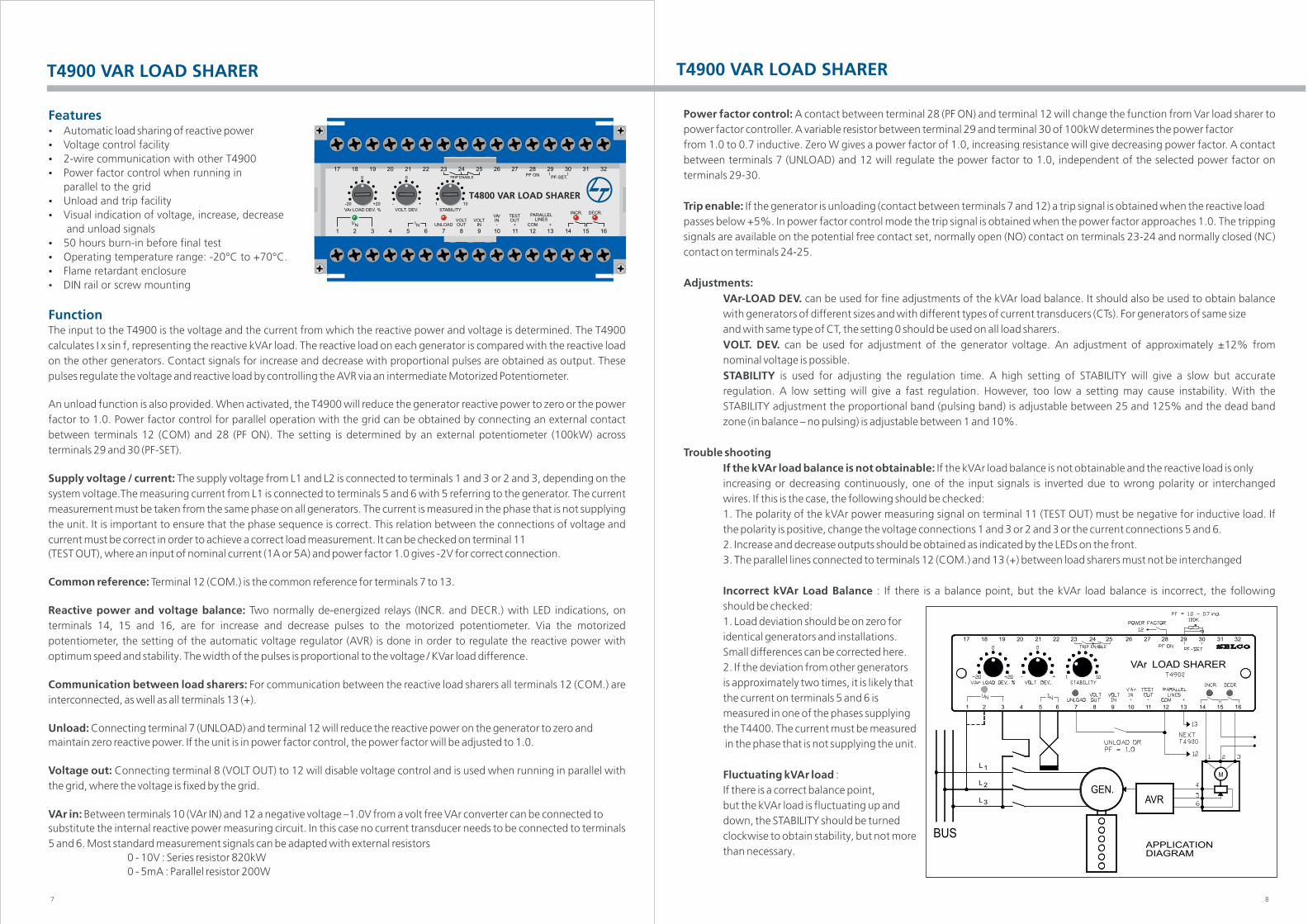
FunctionThe input to the T4900 is the voltage and the current from which the reactive power and voltage is determined. The T4900
calculates I x sin f, representing the reactive kVAr load. The reactive load on each generator is compared with the reactive load
on the other generators. Contact signals for increase and decrease with proportional pulses are obtained as output. These
pulses regulate the voltage and reactive load by controlling the AVR via an intermediate Motorized Potentiometer.
An unload function is also provided. When activated, the T4900 will reduce the generator reactive power to zero or the power
factor to 1.0. Power factor control for parallel operation with the grid can be obtained by connecting an external contact
between terminals 12 (COM) and 28 (PF ON). The setting is determined by an external potentiometer (100kW) across
terminals 29 and 30 (PF-SET).
Supply voltage / current: The supply voltage from L1 and L2 is connected to terminals 1 and 3 or 2 and 3, depending on the
system voltage.The measuring current from L1 is connected to terminals 5 and 6 with 5 referring to the generator. The current
measurement must be taken from the same phase on all generators. The current is measured in the phase that is not supplying
the unit. It is important to ensure that the phase sequence is correct. This relation between the connections of voltage and
current must be correct in order to achieve a correct load measurement. It can be checked on terminal 11
(TEST OUT), where an input of nominal current (1A or 5A) and power factor 1.0 gives -2V for correct connection.
Common reference: Terminal 12 (COM.) is the common reference for terminals 7 to 13.
Reactive power and voltage balance: Two normally de-energized relays (INCR. and DECR.) with LED indications, on
terminals 14, 15 and 16, are for increase and decrease pulses to the motorized potentiometer. Via the motorized
potentiometer, the setting of the automatic voltage regulator (AVR) is done in order to regulate the reactive power with
optimum speed and stability. The width of the pulses is proportional to the voltage / KVar load difference.
Communication between load sharers: For communication between the reactive load sharers all terminals 12 (COM.) are
interconnected, as well as all terminals 13 (+).
Unload: Connecting terminal 7 (UNLOAD) and terminal 12 will reduce the reactive power on the generator to zero and
maintain zero reactive power. If the unit is in power factor control, the power factor will be adjusted to 1.0.
Voltage out: Connecting terminal 8 (VOLT OUT) to 12 will disable voltage control and is used when running in parallel with
the grid, where the voltage is fixed by the grid.
VAr in: Between terminals 10 (VAr IN) and 12 a negative voltage –1.0V from a volt free VAr converter can be connected to
substitute the internal reactive power measuring circuit. In this case no current transducer needs to be connected to terminals
5 and 6. Most standard measurement signals can be adapted with external resistors
0 - 10V : Series resistor 820kW
0 - 5mA : Parallel resistor 200W
Power factor control: A contact between terminal 28 (PF ON) and terminal 12 will change the function from Var load sharer to
power factor controller. A variable resistor between terminal 29 and terminal 30 of 100kW determines the power factor
from 1.0 to 0.7 inductive. Zero W gives a power factor of 1.0, increasing resistance will give decreasing power factor. A contact
between terminals 7 (UNLOAD) and 12 will regulate the power factor to 1.0, independent of the selected power factor on
terminals 29-30.
Trip enable: If the generator is unloading (contact between terminals 7 and 12) a trip signal is obtained when the reactive load
passes below +5%. In power factor control mode the trip signal is obtained when the power factor approaches 1.0. The tripping
signals are available on the potential free contact set, normally open (NO) contact on terminals 23-24 and normally closed (NC)
contact on terminals 24-25.
Adjustments:
can be used for fine adjustments of the kVAr load balance. It should also be used to obtain balanceVAr-LOAD DEV.
with generators of different sizes and with different types of current transducers (CTs). For generators of same size
and with same type of CT, the setting 0 should be used on all load sharers.
can be used for adjustment of the generator voltage. An adjustment of approximately ±12% fromVOLT. DEV.
nominal voltage is possible.
is used for adjusting the regulation time. A high setting of STABILITY will give a slow but accurateSTABILITY
regulation. A low setting will give a fast regulation. However, too low a setting may cause instability. With the
STABILITY adjustment the proportional band (pulsing band) is adjustable between 25 and 125% and the dead band
zone (in balance – no pulsing) is adjustable between 1 and 10%.
Trouble shooting
If the kVAr load balance is not obtainable and the reactive load is onlyIf the kVAr load balance is not obtainable:
increasing or decreasing continuously, one of the input signals is inverted due to wrong polarity or interchanged
wires. If this is the case, the following should be checked:
1. The polarity of the kVAr power measuring signal on terminal 11 (TEST OUT) must be negative for inductive load. If
the polarity is positive, change the voltage connections 1 and 3 or 2 and 3 or the current connections 5 and 6.
2. Increase and decrease outputs should be obtained as indicated by the LEDs on the front.
3. The parallel lines connected to terminals 12 (COM.) and 13 (+) between load sharers must not be interchanged
: If there is a balance point, but the kVAr load balance is incorrect, the followingIncorrect kVAr Load Balance
should be checked:
1. Load deviation should be on zero for
identical generators and installations.
Small differences can be corrected here.
2. If the deviation from other generators
is approximately two times, it is likely that
the current on terminals 5 and 6 is
measured in one of the phases supplying
the T4400. The current must be measured
in the phase that is not supplying the unit.
:Fluctuating kVAr load
If there is a correct balance point,
but the kVAr load is fluctuating up and
down, the STABILITY should be turned
clockwise to obtain stability, but not more
than necessary.
24
BUS
L 2
L 3
L 1
1 2
17 18
3 4 5 76
19 2120 2322
APPLICATIONDIAGRAM
GEN.AVR
M
LOAD SHARER
13
29
8 9 10 11 12
VAr
25 26 27 28
14 15 16
30 31 32
T4800 VAR LOAD SHARER

9 10
APPLICATIONST4900 VAR LOAD SHARER
SpecificationMax. voltage 660V
Voltage range 70 - 110%
Consumption Voltage 4VA at UN Current 0.4VA at INContinuous current 2 x INFrequency range 35 - 70Hz
Frequency adjustment 48 - 62Hz
Proportional band ±50 - 250% load ±5 - 25% frequency
Dead band zone ±2 - 10% load ±0.2 - 1.0% frequency
Contact rating AC: 400V, 2A, 250VA DC: 110V, 2A, 100W
Operating temperature -20°C to +70°C
Vibration test 4g RMS according to IEC 60068-2-64
EMC CE according to EN50081-1, EN50082-1, EN50081-2,EN50082-2, EN61000-6-2:1999Burn-in 50 hours before final test
Enclosure material Polycarbonate, flame retardant
Weight 0.7kg
Dimensions 70 x 150 x 115mm (H x W x D)
Installation 35 DIN rail or two 4mm (3/16”) screws
Terminals
Type Selection Table
TerminalsType 1-3, 5-7 2-3, 6-7 IN
T4800.0010 450V 400V 5AT4800.0020 230V 5A
T4800.0030 480V 415V 5AT4800.0040 110V 100V 1A
T4800.0050 450V 400V 1A
T4800.0060 127V 120V 5A
T4800.0070 110V 100V 5A
Other supply voltages, nominal currents and combinations are available on request.
Synchronization and load sharing with T4500 and T4800 using conventional governors
BUS
Synchronization and load sharing with T4500, T4800 using electronic governors
ELEC.GOV.
WITHDROOP
ELEC.GOV.
1 2 3
4
5
6
E7800
WITHDROOP
1 2 3
4
5
6
BUS
115
70Dimensions in mm.
150
50
10
7.5 135
Fixing holes2 x ø 4.5 mm.
Dimension (T4800 & T4900)
Type Approvals and Certificates (T4500, T4800)The T4800 has been designed and tested for use in harsh environments. The unit is based on standard components, providinglong term durability. The T4800 carries the CE label and has been approved by the following marine classification societies:� American Bureau of Shipping� Bureau Veritas� Croatian Register of Shipping� Germanischer Lloyd� Korean Register of Shipping� Romanian Register of Shipping� Russian Maritime Register of Shipping

APPLICATIONST4900 VAR LOAD SHARER
11 12
Synchronizing two generators on load sharing to the grid with T4500
SYNCHRONIZERT4500
LOAD SHARERT4800
LOAD SHARERT4800
GRID
BUS
Active- and reactive load sharing.
DE
CR
EA
SE
INC
RE
AS
E
1
MOTORPOT.
1 2
SUPPLY
MOTOR
AVR
DROOP
5
6
34
BUSBAR
3L
2L
VAr LOAD SHARERT4900
VAr -UNLOAD
GEN.1514
12
7
12
13
FROMT4900
13
12
13
TO NEXTT4900
16
1
6
5
L
3
2
GEN.DROOP
M
SUPPLY
MOTOR
LOAD SHARERT4800
16
IN-CREASE
14 15
1
6
5
2
3
UNLOADGEN.
DE-CREASE
12
7
13
FROMT4800 13
12
13
12 TO NEXTT4800
BUS
Single generator with constant grid load and power factor regulation
DE
CR
EA
SE
L
L
L
SUPPLYMOTOR
INC
RE
AS
E
GEN.AVR
1
2
3
5
6
3
2
1
14
VAr LOAD SHARERT490012
VAr -UNLOADGRID
7
28
1615
3029
POWER FACTORREGULATOR
INDUCTIVE PF SET
5
6
3
2
1
GRID
DE
CR
EA
SE
SUPPLY
M
INC
RE
AS
E
MOTOR
CONSUMER
14 1615
LOAD SHARERT4800
12
UNLOADGRID
7
13
LOADREGULATOR
POWERREFERENCEB9300-xx-103
5
IMPORTPOWER SET
BUS
MOTORPOT.