t71001l - m.media-amazon.com
TRANSCRIPT

OWNER’S MANUAL
T71001L
10-TON HYDRAULIC RAM SYSTEM
WARNING:
Questions, problems, missing parts? Before returning to your retailer, call our customer service
department at 1-888-448-6746, 8 a.m.- 5 p.m., PST, Monday-Friday.
Read carefully and understand all ASSEMBLY AND OPERATION INSTRUCTIONS before operating.
Failure to follow the safety rules and other basic safety precautions may result in serious personal injury.

2
IMPORTANT
Before You Begin Register This Product.
For future reference, record the model name, model number, date of manufacture and purchase date of
this product. You can find this information on the product.
Model Name _________________________
Model Number _________________________
Date of Manufacture _________________________
Date of Purchase _________________________
OWNER / USER RESPONSIBILITY
DO NOT OPERATE OR REPAIR THIS PRODUCT WITHOUT READING THIS MANUAL.
Read and follow the safety instructions. Keep Instructions readily available for operators. Make certain
all operators are properly trained and understand how to safely and correctly operate the product. By
proceeding you agree that you fully understand and comprehend the full contents of this manual. Failure
to operate this product as intended may cause injury or death. The manufacturer is not responsible for
any damages or injury caused by improper use or neglect. Allow product operation only with all parts in
place and operating safely. Use only genuine replacement parts. Service and maintain the product only
with authorized or approved replacement parts; negligence will make the product unsafe for use and will
void the warranty. Carefully inspect the product on a regular basis and perform all maintenance as
required. Store these instructions in a protected dry location. Keep all decals on the product clean and
visible. Do not modify and/or use for any application other than that for which this product was designed.
If you have any questions relative to a particular application, DO NOT use the product until you have first
contacted the distributor or manufacturer to determine if it can or should be performed on the product.
For technical questions please call 1-888-448-6746.

3
INTENDED USE
Portable Power Kits are designed to be used for pushing, spreading, and pressing of vehicle body
panels as well as various component parts and assemblies.
TECHNICAL SPECIFICATIONS
Description
Application Manual
Capacity 10 Ton
Operating PSI 8,939
Max. Lift Height 20-7/8 in.
Min. Lift Height 14-15/16 in.
Dimensions L x W x H 20 7/16in. x 5 3/16in. x 5 ½ in.
Case Included Yes
Safe Operating Temperature is between 40°F – 105°F (4°C - 41°C)
GENERAL SAFETY RULES
WARNING: Read and understand all instructions. Failure to follow all instructions listed
below may result in serious injury.
CAUTION: Do not allow persons to operate or assemble this Product until they have read
this manual and have developed a thorough understanding of how the Product works.
WARNING: The warnings, cautions, and instructions discussed in this instruction
manual cannot cover all possible conditions or situations that could occur. It must be understood
by the operator that common sense and caution are factors which cannot be built into this product, but
must be supplied by the operator.
SAVE THESE INSTRUCTIONS

4
IMPORTANT SAFETY CONSIDERATIONS
PLEASE READ THESE INSTRUCTIONS CAREFULLY. NOTE THE SAFETY INSTRUCTIONS AND
WARNING. USE THE PRODUCT CORRECTLY AND WITH CARE FOR THE PURPOSE OF WHICH IT
IS INTENDED. FAILURE TO DO SO MAY CAUSE DAMAGE TO PROPERTY AND/OR SERIOUS
PERSONAL INJURY. PLEASE KEEP THIS INSTRUCTION MANUAL SAFE FOR FUTURE USE.
We’ve done all we can to assure this equipment offers the outmost in safety, but you have to do your part.
No amount of warning can take the place of your good judgment, so make sure it’s the first thing you
bring to any job. Beyond that here are some obvious tips:
Steel and other materials can shatter, so always use ANSI approved impact safety goggles, full-face
impact safety shield and heavy-duty work gloves when operating.
Remove loose fitting clothing. Remove ties, watches, rings and other loose jewelry and contain long
hair.
Keep proper balance and footing, do not over-reach and wear nonskid footwear.
Do not operate the when you are tired or under the influence of alcohol, drugs or an intoxicating
medication.
Keep hands and feet away from work area at all times.
Do not allow untrained persons to operate the equipment.
If you detect anything that may indicate imminent structural failure, stop using the product
immediately and inspect it thoroughly.
Do not use to compress springs or any other item that could disengage and cause a potential flying
hazard.
Use this equipment for the purpose for which it is intended. Do not use it for any other purpose it is
not designed to perform.
Keep children and unauthorized persons away from the work area.
Only use this equipment on a surface that is stable, level, dry and not slippery, and capable of
sustaining the load. Keep the surface clean, tidy and free form unrelated materials and ensure that
there is adequate lighting.
Inspect before each use. Do not use if bent, broke, cracked, leaking or otherwise damaged.
Use extreme caution when working around any parts that are subjected to a shock load.
Check to ensure that all applicable bolts and nuts are firmly tightened.
Ensure that work piece is center-loaded and secure.
Do not make any modifications to the equipment.
Do not use brake fluid or any other improper fluid and avoid mixing different types of oil when adding
hydraulic oil. Only good quality hydraulic jack oil can be used in equipment.
Do not expose the equipment to rain or any other kind of bad weather.
If the equipment needs repairing and/or there are any parts that need to be replaced, have it
repaired by authorized technicians and only use the replacement parts supplied by the
manufacturer.

5
WARNING: To reduce the risk of personal injury and/or property damage, ensure that the
rated working pressure of each pressurized attachment be equal to or greater than the rated working
pressure developed by the hydraulic pump.
Always check connections before using. Alteration of these products is strictly prohibited. Use only
those adapters and attachments provided and approved by the manufacturer。
Note: when extension tubes and/or offset attachments are used, the rated capacity is always
reduced by 50% for each tube or offset attachment connected.
Manufacturer does not assume any liability for use of this product to any property or damaged
caused. Use of this item is completely determined by user. Manufacturer has included example
uses for items included in kit. User will assume all responsibility of possible property or damage
caused.
RAM KIT USE AND CARE
Do not modify the ram kit in any way. Unauthorized modification may impair the function and/or
safety and could affect the life of the equipment. There are specific applications for which the Ram
Kit was designed.
Always check of damaged or worn out parts before using the Ram Kit. Broken parts will affect
the Ram Kit operation. Replace or repair damaged or worn parts immediately.
Store idle. When Ram Kit is not in use, store it in a secure place out of the reach of children. Inspect
it for good working condition prior to storage and before re-use.
Not for use by children or people with reduced mental capacity.
Do not use under the influence of drugs or alcohol.
Ensure children and other bystanders are kept at a safe distance when using Ram Kit.
INSPECTION
Inspect the Ram Kit carefully before each use. Ensure the Product is not damaged, excessively worn,
or missing parts.
Do not use the Ram Kit unless it is properly lubricated.
Using a Ram Kit that is not in good clean working condition or properly lubricated may cause serious
injury.
Inspect the work area before each use. Make sure it is free and clear of any potential hazards.

6
GENERAL SAFETY RULES
Save these instructions.
For your safety, read, understand, and follow the information provided with and on this product
before using.
The owner and/or operator of this equipment shall have an understanding of safe use/operating
procedures before attempting to use.
The owner and/or operator shall be aware that the use of this product may require special skills and
knowledge.
Instructions and safety information shall be conveyed in the operator's native language before use of
this device is authorized.
If any doubt exists as to the safe and proper use of this product as outlined in this factory authorized
manual, remove from service immediately.
Inspect before each use.
Do not use if broken, bent cracked, or damaged parts (including labels) are noted.
If the product appears damaged in any way, operates abnormally or is missing parts, it should be
removed from service immediately and the distributor should be notified.
If you suspect that the product was subjected to a shock load (a load suddenly dropped
unexpectedly upon it), immediately discontinue use until product has been clocked by a factory
authorized service center (contact distributor or manufacturer for list of Authorized Service Centers).
It is recommended that an annual inspection be done by qualified personnel.
Labels and owner's manuals are available from the distributor.
SAFETY MARKINGS
WARNING:
1. Study, understand, and follow all instructions before operating this device.
2. Wear eye protection that meets ANSI Z87.1 and OSHA standards.
3. Do not exceed the rated capacity.
4. Use a pressure gauge that indicates pounds of force applied.
5. Inspect before each use.
6. When using extension tubes, position the shortest tube farthest from the cylinder.
7. Do not subject the hose to extreme cold, heat, sharp surfaces, abrasion, or impact.
8. Do not allow the hose to kink, twist, curl, or bend so tightly that it restricts fluid flow.
9. Make sure setup is stable and secure before performing any work.
10. No alterations or modifications shall be made to this product.
11. Only components supplied with this kit shall be used with this kit.
12. Do not use this product for any use other than the manufacturer specified usage.
13. Failure to heed these markings may result in personal injury, property damage, or both.

7
ASSEMBLY
To assemble Hydraulic Ram, Pump Unit, and Attachments
1. Unscrew and save the End Plugs located on the
ends of the Hose and Hydraulic Ram.
2. Securely screw the Hose into the Hydraulic Ram.
3. Insert the Pump Handle into the receptacle
located at the top of the Pump Unit.
4. To attach the Rubber Head, the Extension
Bars, the Male Connector, and the Flat Base to
the Hydraulic Ram.
5. To attach the Spreader Wedge to the Pump
Unit.
6. For other attachment combinations.

8
SYSTEM AIR PURGE PROCEDURE
Perform the following Air Purge Procedure to remove any air that may have been introduced into the
hydraulic system as a result of product shipment and handing. This step is to be completed without any
load pressure.
1. Firmly close the Release Valve by turning it clockwise.
2. Press the tip of the Hydraulic Hose Coupling against a hard surface and pump the pump handle.
3. Continue pumping until the hydraulic fluid coming out from the end of the coupler tip is free of air
bubbles.
4. Check the oil level and add oil if necessary. (See instruction in Maintenance Section “To Add Oil”.)
5. Turn the Release Valve counter-clockwise to release the pressure in the pump and hose.

9
BEFORE USE
1. Before using this product, read the owner's manual completely and familiarize yourself thoroughly
with the product and the hazards associated with its improper use.
2. Perform the air purge procedure. (See previous instructions for system purge procedure.)
3. Inspect before each use. Do not use if bent, broken or cracked components are noted.
OPERATION
To Operate the Hydraulic Pump Unit
1. Position the Pump Unit on a stable, flat and level surface.
2. Close the release valve by turning it clockwise until it is firmly closed.
Pump Handle to apply pressure.
3. Turn the Release Valve Stem counterclockwise to release the pressure.
Note:
The Pump Unit may be positioned horizontally or vertically.
When using the Hydraulic Unit in a vertical position, always keep the Hose end of the Hydraulic Unit
downward.

10
Example: To Repair Frame Damage
1. Determine which direction the frame needs to straighten.
2. Remove any obstructions that could be damaged or are in the way.
3. Connect the Flat Base to the stationary side of the Hydraulic Ram and connect the appropriate
attachment to the pushing end of the Stroke Ram.
4. Position the Hydraulic Ram so that the Flat Base is resting against a frame member opposite the
damaged area. It must also be in line with the direction in which the damaged area needs to be
pushed.
5. Aim the pushing end towards the area that needs to be repaired and slowly apply pressure with the
Pump Unit. Once contact has been made on both points of contact, step away as far as possible and
continue to slowly apply pressure to the damaged area until the desired bend has been made.
CAUTION: Keep hands away from contact areas and tight spaces. The Portable Power Kit may
slip and cause injury.
6. When the damaged area has been bent to the desired position, slowly turn the Release Valve on the
Pump Unit in a counterclockwise direction to release the hydraulic pressure and cautiously remove
the Hydraulic Ram.

11
Example: To Repair Sheet Metal Damage
1. Determine which direction the body panel should be moved.
2. Remove any obstructions that could be damaged or are in the way.
3. Connect the appropriate attachments to the Hydraulic Ram.
Note: When repairing larger body panel dents such as a piece of sheet metal, dented door, fender or
suggested use is the Rubber Head.
4. Attachment must also be in line with the direction in which the damaged area needs to be pushed. A
hard secure surface will be required for to apply pressure on opposing sides.
A block of wood or a towel may be used to protect the sheet metal.
5. Aim the pushing end towards the area that needs to be repaired and slowly apply pressure with the
Pump Unit. Once contact has been made on both points of contact, step away as far as possible and
continue to slowly apply pressure to the damaged area until the desired bend has been made.
6. When the damaged area has been bent to the desired position, slowly turn the Release Valve on the
Pump Unit in a counter-clockwise direction to release the hydraulic pressure and remove the
Hydraulic Ram.

12
Example: To Use the Spreader Wedge
1. Determine which direction part needs to be bent.
2. Remove any obstructions that could be damaged or are in the way.
3. Place Spreader Wedge so that the hinged arm is resting against the part to be moved and the
stationary arm is resting against a non-movable base. Hold the Spreader Ram in position and apply
the Pump Unit pressure. Once contact on either end has been made, step away as far as possible
and continued to slowly apply pressure to the damaged area until the desired bend has been made.
4. When the damaged area has been bent to the desired position, slowly turn the Release Valve Stem
on the Pump Unit in a counterclockwise direction to release the hydraulic pressure and remove the
Hydraulic Ram.

13
MAINTENANCE INSTRUCTIONS
If you use and maintain your equipment properly, it will give you many years of service. Follow the
maintenance instructions carefully to keep your equipment in good working condition. Never perform any
maintenance on the equipment while it is under a load.
Inspection
You should inspect the product for damage, wear, broken or missing parts (e.g.: pins) and that all
components function before each use. Follow lubrication and storage instructions for optimum product
performance.
Binding
If the product binds while under a load, use equipment with equal or a larger load capacity to lower the load
safely to the ground. After un-binding; clean, lubricate and test that equipment is working properly. Rusty
components, dirt, or worn parts can be causes of binding Clean and lubricate the equipment as indicated in
the lubrication section. Test the equipment by lifting without a load. If the binding continues, contact Customer
Service.
Cleaning
If the moving parts of the equipment are obstructed, use cleaning solvent or another good degreaser to clean
the equipment. Remove any existing rust, with a penetrating lubricant.
Lubrication
This equipment will not operate safely without proper lubrication. Using the equipment without proper
lubrication will result in poor performance and damage to the equipment. Some parts in this equipment are
not self-lubricating inspect the equipment before use and lubricate when necessary. After cleaning, lubricate
the equipment using light penetrating oil or lubricating spray.
-Use a good lubricant on all moving parts.
-For light duty use, lubrication is needed once a month.
-For heavy and constant use, lubrication is recommended every week.
-NEVER USE SANDPAPER OR ABRASIVE MATERIAL ON THESE SURFACES!
Rust Prevention:
-Check rams and pump plungers on the power unit assemblies daily for any signs of rust or corrosion.
Without a load lift the equipment as high as it goes and look under and behind the lifting points. If signs of
rust are visible clean as needed.
How the Equipment Operates
With release valve closed, an upward stroke of the handle draws oil from the reservoir tank into the plunger
cavity. Hydraulic pressure holds the valve closed, which keeps the oil in the plunger cavity. A downward
stroke of the handle releases oil into the cylinder, which forces the ram out. This raises the saddle. When the
ram reaches maximum extension, oil is bypassed back into the reservoir to prevent an over extended ram
stroke and possible damage to the unit. Opening the release valve allows oil to flow back into reservoir. This
releases hydraulic pressure on the ram, which results in lowering the ram.
Storing the Product
1. Lower to the lowest resting position.
2. Place the handle in the resting position.
3. Store in a dry location, recommended indoors.
Note: If the equipment is stored outdoors, be sure to lubricate all parts before and after use to ensure the
equipment stays in good working condition.

TO ADD OIL TO HYDRAULIC PUMP UNIT:
After extensive use, the hydraulic oil supply
should be replaced to ensure longer equipment
life.
1. Set Pump Unit upright on a level surface.
2. Remove the Screw with its attached dipstick.
3. Add 0.24 Qts (approximately 7.68oz./ 220ml)
of oil. The oil level should be near position A.
Use a high grade anti-foaming hydraulic oil.
KEEP DIRT AND OTHER MATERIALS
CLEAR WHEN POURING.
4. Replace the Oil Fill Screw.
5. Perform the Air Purge Procedure.
TO REPLACE OIL TO HYDRAULIC PUMP UNIT :
1. Set Pump Unit flat on a level surface.
Remove the screw with its attached dipstick.
2. Turn the Pump Unit on its side so that old oil
will drain from the oil fill hole.
3. Set Pump Unit upright on a level surface.
4. Add (0.24 Qts / 220ML) of oil. The oil level
should be near position A.
Use a high grade anti-foaming hydraulic oil.
KEEP DIRT AND OTHER MATERIALS
CLEAR WHEN POURING.
6. Replace the Oil Fill Screw.
7. Perform the Air Purge Procedure.

ADDITIONAL WARNINGS:
DO NOT USE MOTOR OIL IN THE JACK.
ONLY USE ANTI-FOAMING JACK OIL.
ALWAYS USE A GOOD GRADE HYDRAULIC JACK OIL.
DO NOT USE HYDRAULIC BRAKE FLUID, ALCOHOL, GLYCERINE, DETERGENT, MOTOR OIL OR
DIRTY OIL.
USE OF A NON-RECOMMENDED FLUID CANCAUSE DAMAGE TO A JACK.
AVOID MIXING DIFFERENT TYPES OF FLUID AND NEVER USE BRAKE FLUID, TURBINE OIL,
TRANSMISSION FLUID, MOTOR OIL OR GLYCERIN. IMPROPER FLUID CAN CAUSE PREMATURE
FAILURE OF THE JACK AND THE POTENTIAL FOR SUDDEN AND IMMEDIATE LOSS OF LOAD.
DISPOSE OF HYDRAULIC FLUID IN ACCORDANCE WITH LOCAL REGULATIONS.
LUBRICATION
1. When not in use, the Pump Unit should be stored with the Release Valve open and the Pump Piston
fully retracted.
2. A coating of light lubricating oil to pivot points, axles and hinges will help to prevent rust.
3. Periodically check the Pump Piston and Rams for signs of rust or corrosion. Clean as needed and
wipe with a soft non-abrasive clean cloth.
4. When Cylinder Rams are not in use, store ram fully retracted. Clean as needed and wipe with a soft
non-abrasive clean cloth.

16
TROUBLESHOOTING
Ram won’t lift
load
Ram won’t maintain
hold
Ram won’t lower after unloading
Ram won’t extend to full stroke
Poor performance
CAUSES AND SOLUTIONS
Releases valve not tightly closed. Firmly close release valve.
Weight Capacity Exceeded.
Air is in the hydraulics. Purge air from system.
Low oil level. Add oil as required.
Oil reservoir is overfilled: Drain excessive oil. Lubricate moving parts.
Hydraulic unit malfunction. Replace ram and / or pump.

17
ASSEMBLY DIAGRAM
ASSEMBLY PARTS LIST
Index # Description Part Number Qty.
1 Extension Tube 27” QF10.10(27”) 1
2 Extension Tube 18” QF10.10(18”) 1
3 Extension Tube 10” QF10.10(10”) 1
4 Extension Tube 5” QF10.10(5”) 1
5 Pump Unit QF10.0(PUMP) 1
6 Ram Assembly QF10.0(RAM) 1
7 Spreader(1000lb.Capacity) QF4.7 1
8 Serrated Saddle QF10.7a 1
9 Combination Head QF10.6 1
10 Wedge Head(offset) QF10.5 1
11 Rubber Head QF10.8 1
12 Plunger Toe(offset) QF10.2a 1
13 Ram Toe(offset) QF10.4 1
14 Flat Base QF10.3a 1
15 Male Connector QF10.9 1

18
PUMP ASSEMBLY
19
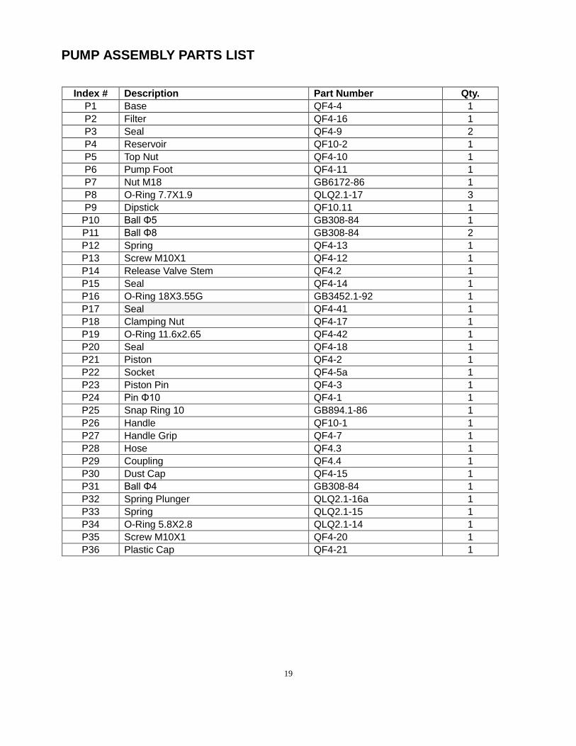
PUMP ASSEMBLY PARTS LIST
Index # Description Part Number Qty.
P1 Base QF4-4 1
P2 Filter QF4-16 1
P3 Seal QF4-9 2
P4 Reservoir QF10-2 1
P5 Top Nut QF4-10 1
P6 Pump Foot QF4-11 1
P7 Nut M18 GB6172-86 1
P8 O-Ring 7.7X1.9 QLQ2.1-17 3
P9 Dipstick QF10.11 1
P10 Ball Φ5 GB308-84 1
P11 Ball Φ8 GB308-84 2
P12 Spring QF4-13 1
P13 Screw M10X1 QF4-12 1
P14 Release Valve Stem QF4.2 1
P15 Seal QF4-14 1
P16 O-Ring 18X3.55G GB3452.1-92 1
P17 Seal QF4-41 1
P18 Clamping Nut QF4-17 1
P19 O-Ring 11.6x2.65 QF4-42 1
P20 Seal QF4-18 1
P21 Piston QF4-2 1
P22 Socket QF4-5a 1
P23 Piston Pin QF4-3 1
P24 Pin Φ10 QF4-1 1
P25 Snap Ring 10 GB894.1-86 1
P26 Handle QF10-1 1
P27 Handle Grip QF4-7 1
P28 Hose QF4.3 1
P29 Coupling QF4.4 1
P30 Dust Cap QF4-15 1
P31 Ball Φ4 GB308-84 1
P32 Spring Plunger QLQ2.1-16a 1
P33 Spring QLQ2.1-15 1
P34 O-Ring 5.8X2.8 QLQ2.1-14 1
P35 Screw M10X1 QF4-20 1
P36 Plastic Cap QF4-21 1

20
HYDRAULIC CYLINDER RAM ASSEMBLY

21
HYDRAULIC CYLINDER RAM PARTS LIST
Index # Description Part Number Qty.
1 Cylinder QF10.1 1
2 Retainer Nut M48X1.5 QF10-14 1
3 Protecting Cap QF10-15 1
4 Spring T71003LT-5 1
5 Nut M6 GB41-86 1
6 Screw M6X30 GB70-85 1
7 Ring Snap T71003LT-8 1
8 Dust Cup QF4-34 1
9 Y-Ring TF1008G-10 1
10 Seal Cap TF1008G-11 1
11 Piston Cup T71003LT-7 1
12 O-Ring 24.5X3.1 QF10-9 1
13 Ram T71003LT-6 1
14 Spacing Ring T71003LT-9 1
15 Ring Snap QF10-12 1
16 Protecting Cap QF10-11 1
17 Screw M6X20 GB70-85 1
18 Coupling Valve QF4.6-1 1
NOTE:
Not all equipment components are available for replacement, but are illustrated as a convenient
reference of location and position in the assembly sequence. Contact Customer Service for equivalent
component.
Safe Operating Temperature is between 40°F – 105°F (4°C - 41°C)

22
REPLACEMENT PARTS
Consumers for replacement parts and technical questions call us Monday – Friday between 8am and
5:00pm EST at 1-888-448-6746.
www.torinjacks.com
Please contact our Customer Service Department with any questions you may have concerning parts,
use, or maintenance. Not all equipment components are available for replacement, but are illustrated as
a convenient reference of location and position in the assembly sequence. Contact Customer Service for
equivalent component. When you contact us, please have your Product’s Model number, Serial Number
and Description ready so that we may help you efficiently. This information can be found on a sticker on
the product.
The manufacturer or distributor reserves the right to make design changes and or improvements to
product lines and manuals without notice.
ONE YEAR LIMITED WARRANTY
All products sold are felt to be of the highest quality and are covered by the following warranty:
With proof of purchase for a period of one year from the date of that purchase, the manufacturer will
repair or replace, at its discretion, without charge, any of its products or parts thereof which fail due to a
defect in material or workmanship.
This warranty does not cover damage or defects caused by improper use, careless use or abuse of the
equipment. This warranty does not cover parts normally considered to wear out or be consumed in the
normal operation of the equipment.
Except where such limitations and exclusions are specifically prohibited by applicable law,(1) the
CONSUMER’S SOLE AND EXCLUSIVE REMEDY SHALL BE THE REPAIR OR REPLACEMENT OF
DEFECTIVE PRODUCTS AS DESCRIBED ABOVE, and (2) THE MANUFACTURER SHALL NOT BE
LIABLE FOR ANY CONSEQUENTIAL OR INCIDENTAL DAMAGE OR LOSS WHATSOEVER, and (3)
THE DURATION OF ANY AND ALL EXPRESSED AND IMPLIED WARRANTIES, INCLUDING,
WITHOUT LIMITATION, ANY WARRANTIES OF MERCHANTABILITY AND FITNESS FOR A
PARTICULAR PURPOSE, IS LIMITED TO A PERIOD OF ONE YEAR FROM DATE OF PURCHASE.
_____________________________________________________________________________
Distributed by Torin Jacks, Inc. 4355 E. Brickell St. Ontario, CA 91761 USA