ta ct total -...
TRANSCRIPT

Page 1 of 22
STATE COUNCIL OF TECHNICAL EDUCATION AND VOCATIONAL TRAINING, ODISHA
TEACHING AND EVALUATION SCHEME FOR DIPLOMA IN ENGINEERING COURSES
DISCIPLINE: ELECTRICAL ENGINEERING SEMESTER: 5TH
SL
NO
SUBJECT
CODE
SUBJECT PERIODS EVALUATION SCHEME
L T P INTERNAL
EXAM
END SEM
EXAM
TERM
WORK
PRACTICAL
EXAM
TOTAL
MARKS TA CT Total
THEORY
1. BST -501
OR
HMT 601
ENVIRONMENTAL STUDIES
OR
ENTERPRENEURESHIP AND
MANAGEMENT
5 0 0 10 20 30 70 100
2. EET 501 ENERGY CONVERSION – II 4 1 0 10 20 30 70 100
3. EET 502 POWER ELECTRONICS AND
DRIVES
4 1 0 10 20 30 70 100
4. ETT 521 MICROPROCESSOR & ITS
INTERFACING
4 0 0 10 20 30 70 100
PRACTICAL/TERM WORK
5. EEP 501 ELECTRICAL DRAWING* 6 0 0 100 50 150
6. EEP 502 ELECTRICAL LAB. PRACTICE – II 0 0 6 50 50 100
7. EEP 503 POWER ELECTRONICS LAB. 0 0 3 25 25 50
8. ETP 521 MICROPROCESSOR LAB. 0 0 3 25 25 50
9. LIBRARY STUDY - - 2
GRAND TOTAL 23 2 14 40 80 120 380 150 100 750
Total Contact hours per week: 39
Abbreviations: L-Lecture, T-Tutorial, P-Practical, TA- Teacher’s Assessment, CT- Class test
Minimum Pass Mark in each Theory Subject is 35% and in Practical subject is 50%
* Electrical Drawing Examination shall be conducted by the Council like Theory Examination and Minimum pass mark in End Sem Exam is 35%
& that in term work is 50%

Page 2 of 22
ENVIRONMENTAL STUDIES (Common to all Branches of Engg.)
BST-501 Period/Week: 05 Total Marks: 100
Total Periods: 75 Theory End Exams: 70; CT (20) +IA (10)
Rationale:
Due to various aspects of human developments including the demand of different
kinds of technological innovations, most people have been forgetting that, the Environment in
which they are living is to be maintained under various living standards for the preservation of
better health. The degradation of environment due to industrial growth is very much alarming
due to environmental pollution beyond permissible limits in respect of air, water industrial waste,
noise etc. Therefore, the subject of Environmental Studies to be learnt by every Engineering
student in order to take care of the environmental aspect in each and every activity in the best
possible manner.
OBJECTIVES:
After completion of study of environmental studies, the student will be able to:
1. Gather adequate knowledge of different pollutants, their sources and shall be aware of solid waste management systems and hazardous waste and their effects.
2. Develop awareness towards preservation of environment.
Unit 1: The Multidisciplinary nature of environmental studies (04 periods)
Definition, scope and importance, Need for public awareness.
Unit 2: Natural Resources (12 periods)
Renewable and non renewable resources:
a) Natural resources and associated problems.
Forest resources: Use and over-exploitation, deforestation, case studies, Timber extraction mining, dams and their effects on forests and tribal people.
Water resources: Use and over-utilization of surface and ground water, floods, drought, conflicts over water, dam’s benefits and problems.
Mineral Resources: Use and exploitation, environmental effects of extracting and using mineral resources.
Food Resources: World food problems, changes caused by agriculture and over grazing, effects of modern agriculture, fertilizers- pesticides problems, water logging, salinity, .
Energy Resources: Growing energy need, renewable and non-renewable energy sources, use of alternate energy sources, case studies.
Land Resources: Land as a resource, land degradation, man induces land slides, soil erosion, and desertification.
b) Role of individual in conservation of natural resources. c) Equitable use of resources for sustainable life styles.

Page 3 of 22
Unit 3: Systems (12 periods)
Concept of an eco system.
Structure and function of an eco system.
Producers, consumers, decomposers.
Energy flow in the eco systems.
Ecological succession.
Food chains, food webs and ecological pyramids.
Introduction, types, characteristic features, structure and function of the following eco system:
Forest ecosystem:
Aquatic eco systems (ponds, streams, lakes, rivers, oceans, estuaries).
Unit 4: Biodiversity and it’s Conservation (08 periods)
Introduction-Definition: genetics, species and ecosystem diversity.
Biogeographically classification of India.
Value of biodiversity: consumptive use, productive use, social ethical, aesthetic and optin values.
Biodiversity at global, national and local level.
Threats to biodiversity: Habitats loss, poaching of wild life, man wildlife conflicts.
Unit 5: Environmental Pollution. (18 periods)
Definition Causes, effects and control measures of:
a) Air pollution. b) Water pollution. c) Soil pollution d) Marine pollution e) Noise pollution. f) Thermal pollution g) Nuclear hazards.
Solid waste Management: Causes, effects and control measures of urban and industrial
wastes.
Role of an individual in prevention of pollution.
Disaster management: Floods, earth quake, cyclone and landslides.
Unit 6: Social issues and the Environment (12 periods)
Form unsustainable to sustainable development.
Urban problems related to energy.
Water conservation, rain water harvesting, water shed management.
Resettlement and rehabilitation of people; its problems nd concern.
Environmental ethics: issue and possible solutions.

Page 4 of 22
Climate change, global warming, acid rain, ozone layer depletion, nuclear accidents and holocaust, case studies.
Air (prevention and control of pollution) Act.
Water (prevention and control of pollution) Act.
Public awareness.
Unit 7: Human population and the environment (09 periods)
Population growth and variation among nations.
Population explosion- family welfare program.
Environment and human health.
Human rights.
Value education
Role of information technology in environment and human health.
Recommended Books:
1. Textbook of Environmental studies, Erach Bharucha, #UGC
2. Fundamental concepts in Environmental Studies, D.D. Mishra, S.Chand & Co-Ltd,
3. Text book of Environmental Studies by K.Raghavan Nambiar, SCITECH Publication Pvt. Ltd.
4. Environmental Engineering by V.M.Domkundwar- Dhanpat Rai & Co.
5. Environmental Engineering & Safety by B.K.Mohapatra.

Page 5 of 22
ENTREPRENEURSHIP & MANAGEMENT (Code :HMT-601)
Period/Week: 05 Total Marks: 100
Total Periods: 75 Theory End Exams: 70; CT (20) +IA (10)
(COMMON TO ALL BRANCHES OF ENGG EXCEPT CIVIL/ CSE/ IT)
OBJECTIVES:
On completion of the course, students will be able to :
1. Understand the concept of different forms of organization including MSME and various managerial functions.
2. Understand Entrepreneurship and choose it as a career option after study. 3. Learn about the basic financial accounting and cost control. 4. Know different areas of management relating to stores and purchase, finance,
production, sales and marketing and human resources in an organization. 5. Learn about various reasons of industrial sickness and its remedial measures. 6. Have a comprehensive idea on important legislations relating to employment in Factory.
SYLLABUS
1. Concept of Organization & Enterprise Management: 12 periods 1.1. Meaning, features and components of Business 1.2. Different forms of Business Organizations with features 1.3. Meaning, definitions and importance of management 1.4. Difference between Management & Administration 1.5. Functions of management- Planning, Organizing, Staffing, Directing (including
Motivation, Leadership & Communication), Coordinating and Controlling. 1.6. Principles of Scientific Management.
2. Entrepreneurship & Management of MSME: 12 periods 2.1. Meaning & Need of Entrepreneurship 2.2. Qualities of an Entrepreneur 2.3. Relevance of Entrepreneurship of Socio-economic gain
(Generating national wealth, creating wage & self-employment, developing MSME enterprises, Optimizing human and national resources, building enterprising personalities and society
2.4. Micro, Small and Medium Enterprises. (investment limits of MSME) 2.5. Project Report- PPR & DPR. (Preparation of a PPR) 2.6. Incentives available to MSME as per the latest IPR 2.7. Role of DIC, OSFC, OSIC, IDCO, SIDBI, IPICOL and Commercial Banks in the
context of MSME.

Page 6 of 22
3. Financial Accounting & Cost Control: 12 periods 3.1. Double- entry System of Book –keeping and types of accounts 3.2. Journal, Ledger, Cash Book (different types), Trial balance 3.3. Components of Final Accounts- Trading A/c, Profit & Loss A/c and Balance
Sheet 3.4. Elements of Cost and Preparation of Cost Sheet 3.5. Break-even Analysis
4. Financial Management: 04 periods 4.1. Meaning & Importance 4.2. Finance Functions 4.3. Types of Capital- Fixed & Working Capital 4.4. Components of Working Capital, Working Capital Cycle
5. Stores & Purchase Management: 05 periods
5.1. Inventory Control : Importance & Techniques 5.2. Purchase management-Principles & Procedures 5.3. Important Store Records (Bin Card, Stores Ledger & GRN)
6. Production Management: 04 periods
6.1. Production & Productivity 6.2. Production , Planning & Control- (meaning & steps)
7. Sales & Marketing Management: 08 periods
7.1. Sales & Marketing Management- Meaning & Importance 7.2. Selling Methods 7.3. Product Policy- (Branding, Packaging, Labeling) 7.4. Product-mix, Pricing methods and Sales Promotion including its techniques. 7.5. Advertising & its media
8. Human Resource management: 06 periods
8.1. Need & Importance 8.2. Recruitment & its sources 8.3. Selection- Methods 8.4. Training- Need, & Methods 8.5. Need of Performance Appraisal
Page 7 of 22
9. Industrial Sickness: 04 periods 9.1. Meaning & Symptoms of Sickness 9.2. Causes of Industrial Sickness 9.3. Remedial measures of Sickness
10. Industrial Legislation: 08 periods 10.1. Major Provisions of Factories Act relating to Health, Welfare, Safety,
Accidents, Hours of Work, employment of Women 10.2. Duties and Power of Factory Inspector 10.3. Major Provisions of Employee’s Compensation Act.
Books Recommended
1. Industrial Engineering & Management : O.P.Khanna
2. Entrepreneurship for Engineers : B.Badhei
3. Principles & Practice of Management : L.M.Prasad
4. Industrial Engineering & Management: Banga & Sharma
5. Mercantile Law: N.D.Kapoor
6. Industrial Engineering & production Management: M.Mahajan
7. Industrial Policy Resolution ( latest)

Page 8 of 22
ENERGY CONVERSION – II
Course code: EET 501 Semester 5th
Total Period: 75 Examination 3 hrs
Theory periods: 4P/week Class Test: 20
Tutorial: 1 P/W Teacher’s Assessment: 10
Maximum marks: 100 End Semester Examination: 70
A. Rationale:
Modern industries are mostly equipped with AC machines. So the diploma students of fifth
semester are given a scope to gain the concepts of electrical machines like synchronous generators,
synchronous Motors, induction motors, single phase induction motors and fractional horse power
motors and other special machines. The students are required to be familiar with constructional
features, working principles, starting and speed control methods and performance characteristics with
applications of the machines. Numerical solving makes the student to understand the feature more
clearly. So some numerical are to be solved wherever applicable.
B. Objectives:
1. To describe various parts, their material specification with suitable reasoning and
working principle of induction motors, synchronous motor, synchronous generators,
single phase AC motors and fractional horse power and other special machines.
2. To describe their operating principle and working characteristics, derive torque equation
of three phase motors.
3. To describe the losses and efficiency of all three phase machine like induction motor,
synchronous motor, synchronous generator.
4. To describe methods of starting and speed control of AC motors.
5. To workout problems on synchronous generator and motor, 3-phase induction motor.
6. To describe different test on such three phase machine.
C. TOPIC WISE DISTRIBUTION OF PERIODS
Sl. No. Topics Periods
1. Induction motor 14
2. Alternator 14
3. Synchronous Motor 08
4. Single Phase induction motor 08
5. AC commutator motors 06
6. Special Electric Machine 05
7. Three phase transformers 05
Total 60

Page 9 of 22
D. COURSE CONTENT:
1. THREE PHASE INDUCTION MOTOR
1. 1 Explain and derive production of rotating magnetic field.
1. 2 Explain constructional feature of Squirrel cage and Slip ring induction
motors.
1. 3 Explain principles of operation of 3-phase Induction motor.
1. 4 Explain slip speed, slip and slip relation with rotor quantities.
1. 5 Derive Torque during starting and running and conditions for maximum
torque. (solve numerical problems)
1. 6 Derive Torque-slip characteristics.
1. 7 Derive relation between full load torque and starting torque etc. (solve
numerical problems)
1. 8 Determine the relations between Rotor Copper loss, Rotor output and
Gross Torque, and relationship of slip with rotor copper loss. (solve
numerical problems)
1. 9 Explain and state Methods of starting and different types of starters.
1. 10 Explain speed control by Voltage Control, Rotor resistance control, pole
changing, frequency control methods.
1. 11 Describe plugging applicable to three phase induction motor.
1. 12 Describe different types of motor enclosures.
1. 13 Explain principle of Induction Generator and state its applications.
14
2. ALTERNATOR
2.1 State types of alternator and their constructional features.
2.2 Explain working principle of alternator and establish the relation between
speed and frequency
2.3 Explain terminology in armature winding, and derive expressions for
winding factors (Pitch factor, Distribution factor)
2.4 Explain harmonics, its causes and impact on winding factor.
2.5 Derive E.M.F equation. (Solve numerical problems)
2.6 Explain Armature reaction and its effect on emf at different pf of load.
2.7 Draw the vector diagram of loaded alternator. (Solve numerical problems)
2.8 State and explain testing of alternator (open circuit and short circuit
methods) (Solve numerical problems)
2.9 Determination of voltage regulation of Alternator by direct loading and
synchronous impedance method.
2.10 Explain parallel operation of alternator using synchro-scope, dark and
bright lamp method.
2.11 Explain distribution of load by parallel connected alternators.
14
3. SYNCHRONOUS MOTOR
3.1 Explain constructional feature of Synchronous Motor.
3.2 Explain principles of operation, concept of load angle.
3.3 Explain effect of varying load with constant excitation.
3.4 Explain effect of varying excitation with constant load.
3.5 Derive torque, power developed
3.6 Explain power angle characteristics of cylindrical rotor motor.
3.7 Explain effect of excitation on Armature current and power factor.
3.8 Explain Hunting & function of Damper Bars.
3.9 Describe method of starting of Synchronous motor.
3.10 State application of synchronous motor.
08

Page 10 of 22
4. SINGLE PHASE INDUCTION MOTOR
4.1 Explain Rotating – field theory of 1-phase induction motor.
4.2 Explain Ferrari’s principle.
4.3 Explain Working principle, Torque speed characteristics, performance
characteristics and application of following single phase motors.
4.3.1 Split phase motor.
4.3.2 Capacitor Start motor.
4.3.3 Capacitor start, capacitor run motor
4.3.4 Permanent capacitor type motor
4.3.5 Shaded pole motor.
4.4 Explain the method to change the direction of rotation of above motors
08
5. COMMUTATOR MOTORS
5.1 Explain construction, working principle, running characteristic and
application of single phase series motor.
5.2 Explain construction, working principle and application of Universal
motors.
5.3 Explain working principle of Repulsion start Motor, Repulsion start
Induction run motor, Repulsion Induction motor.
06
6. SPECIAL ELECTRICAL MACHINE
6.1 Principle of Stepper motor.
6.2 Classification of Stepper motor.
6.3 Principle of variable reluctant stepper motor.
6.4 Principle of Permanent magnet stepper motor.
6.5 Principle of hybrid stepper motor.
6.6 Applications of Stepper motor.
05
7. THREE PHASE TRANSFORMERS
7.1 Explain Grouping of winding, Advantages.
7.2 Explain parallel operation of the three phase transformers.
7.3 Explain tap changer (On/Off load tap changing)
7.4 State maintenance of Transformers.
05
Learning Resources:
Sl.No Name of Authors Title of the Book Name of the publisher
1 B L Theraja, A K Theraja A text book of Electrical
Technology Part-II
S Chand
2 Asfaq Husain Electrical Machine Dhanpat Rai and Sons
3 J B Gupta Electrical Machines S K Kataria and Sons
4 D P Kothari, I J Nagrath Electric Machines Mc Graw Hill
5 S K Bhattacharya Electric Machines Mc Graw Hill

Page 11 of 22
POWER ELECTRONICS AND DRIVES
Course code: EET 502 Semester 5th
Total Period: 75 Examination 3 hrs
Theory periods: 4P/week Class Test: 20
Tutorial: 1 P/W Teacher’s Assessment: 10
Maximum marks: 100 End Semester Examination: 70
A. Rationale:
The development of high power semiconductor devices has facilitated electronic control
techniques for electrical power control in a simple, economic and efficient manner. Thus a new area of
power electronics has now emerged which replaced the old and bulky method of power control
through the use of small electronic devices. Power electronics application has occupied an
indispensible position in industrial applications like heating, welding, uninterrupted power supply,
battery charging etc. Industrial drives, lighting control are most efficiently controlled by power
electronics devices to achieve optimum performance. The objective of this paper ‘Power Electronics
Drives’ is to make final year Diploma students familiar with the principles and operations of Power
electronics devices in Industrial applications with drives control.
B. Objectives:
The subject will facilitate the student to :
1. Understand construction, working principle & application of various power electronics
devices.
2. Know different gate triggering circuits. and commutation methods
3. Understand working principle of phase controlled rectifier.
4. Know the types and working principle of inverter.
5. Understand working principle and voltage control of chopper.
6. Understand frequency variation using Cyclo converter.
7. Understand control principle of AC & DC industrial drive.
8. Know different application of SCR / Thyristor.
.
C. TOPIC WISE DISTRIBUTION OF PERIODS
Sl. No. Topics Periods
1. Thyristor: 8
2. Firing Circuits For Thyristor 6
3. Phase Controlled Rectifier 8
4. Inverter 8
5. Chopper 5
6. Cyclo Converter 4
7. Power Semiconductor Devices 5
8. Thyristor Applications 8
9. A.C & D.C Drives 8
Total 60

Page 12 of 22
D. COURSE CONTENT:
1. THYRISTOR:
1.1 Principle of operation of SCR (Thyristors).
1.2 Static V-I Characteristics of Thyristor.
1.3 Two transistor analogy of Thyristor.
1.4 Gate characteristics of Thyristor.
1.5 Switching characteristic of Thyristor during turn on and turn off.
1.6 Turn on methods of Thyristor.
1.7 Turn off methods of SCR (Line commutation and Forced commutation)
1.7.1 Load Commutation
1.7.2 Resonant pulse commutation
1.8 Voltage and Current ratings of Thyristor.
1.9 Protection of Thyristor
1.9.1 Over voltage protection
1.9.2 Over current protection
1.9.3 Gate protection
8
2. FIRING CIRCUITS FOR THYRISTOR:
2.1 Firing principle of SCR
2.1.1 Gate current amplitude
2.1.2 Gate pulse duration.
2.2 Gate triggering circuits:
2.2.1 Resistance firing
2.2.2 Resistance capacitance firing.
2.3 Uni-junction Transistor
2.3.1 Basic operation,
2.3.2 UJT Relaxation Oscillator.
2.3.3 Gate Triggering of SCR using UJT oscillator circuit.
2.4 Use of Pulse Transformer and Optical Isolator in firing circuit.
6
3. PHASE CONTROLLED RECTIFIER (CONVERTER)
[PRINCIPLE OF OPERATION WITH CIRCUIT DIAGRAM AND EQUATION
TO D.C. VALUE OF VOLTAGE AND CURRENT EQUATION ONLY]
3. 1. Introduction,
3. 2. Phase Angle control and quadrant of operation.
3. 3. Single phase half wave converter with R and R-L load.
3. 4. Single phase half wave converter with R-L load and freewheeling diode.
3. 5. Midpoint converter
3. 6. Bridge converter
3. 7. Single phase full wave converter with R and R-L load.
3. 8. Single phase full wave converter with R-L load and freewheeling diode.
3. 9. Single phase half controlled bridge convertor for R and R-L load.
3. 10. Power factor improvement.
3. 11. Three- phase full wave phase control Rectifier with resistive load.
.
8
Page 13 of 22
4. INVERTER
4. 1. Introduction.
4. 2. Inverter classification.
4. 3. Voltage source series inverter.
4. 4. Voltage source Parallel inverter (single phase).
4. 5. Single phase Voltage source half and full Bridge Inverter with resistive
load
4. 6. Single phase Current source Inverter with ideal Switches
4. 7. Single phase Capacitor commutated CSI with R Load.
4. 8. Single phase auto-sequential commutated inverter
8
5. CHOPPER
(PRINCIPLE OF OPERATION WITH CIRCUIT DIAGRAM)
5.1 Principle of step down and step up chopper operation
5.2 Control strategy of chopper.
5.3 Chopper configuration and quadrant of operation.
5.4 Type A, B, C, D and E chopper.
5.5 Chopper source filter.
5
6. CYCLO CONVERTER
(PRINCIPLE OF OPERATION WITH CIRCUIT DIAGRAM)
6. 1. Principle of Cyclo-converter operation.
6.1.1 Single phase to single phase circuit step up Cyclo converter
6.1.2 Single phase to single phase circuit step down Cyclo converter
4
7. POWER SEMICONDUCTOR DEVICES AND ITS PROTECTION
7. 1. Construction and principle of operation of Power Diode, BJT, MOSFET
and IGBT.
5
8. THYRISTOR APPLICATIONS
8. 1. Single phase half wave and full wave A. C regulator with resistance load.
8. 2. Switch mode power supply
8.2.1. Buck converter.
8.2.2. Boost converter.
8.2.3. Buck-boost converter.
8.2.4. Bridge converter.
8. 3. Uninterruptable power supply (principle & operation).
8
9. A.C & D.C DRIVES
9.1 Single phase half wave converter DC drive.
9.2 Single phase Semi converter DC drive.
9.3 Single phase Full Converter DC drive.
9.4 Chopper drive used for single quadrant Motoring control
9.5 Chopper drive used for single quadrant regenerative braking control
8

Page 14 of 22
9.6 Speed control of Induction motor
9.6.1 Stator voltage control.
9.6.2 Stator frequency control
9.6.3 Stator voltage and frequency control
9.6.4 Slip energy recovery control
Learning Resources:
Sl.No Name of Authors Title of the Book Name of the publisher
1 M. D. Singh and K.B
Khanchandani
Power Electronics TMH
2 Dr. P. S. Bhimbhra Power Electronics Khanna Publisher
3 M H Rashid Power Electronics PHI
4 P C Sen Power Electronics TMH
5 N Mohan Power Electronics Willey (India)
Page 15 of 22
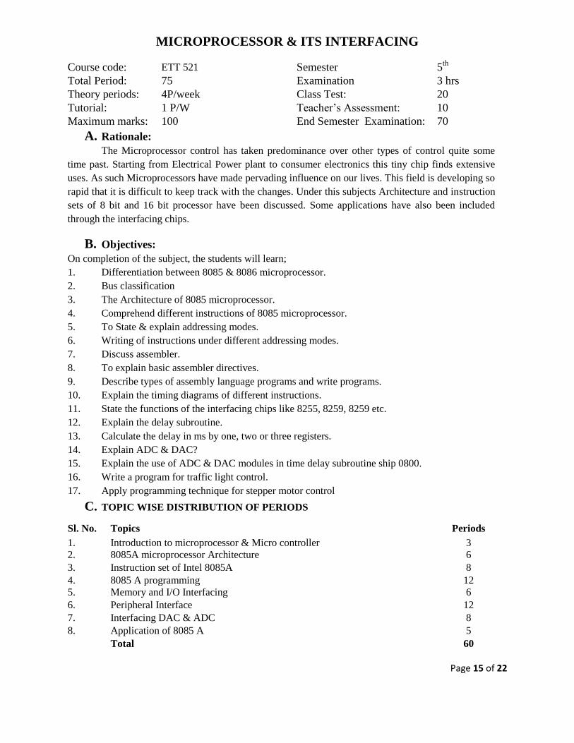
MICROPROCESSOR & ITS INTERFACING
Course code: ETT 521 Semester 5th
Total Period: 75 Examination 3 hrs
Theory periods: 4P/week Class Test: 20
Tutorial: 1 P/W Teacher’s Assessment: 10
Maximum marks: 100 End Semester Examination: 70
A. Rationale:
The Microprocessor control has taken predominance over other types of control quite some
time past. Starting from Electrical Power plant to consumer electronics this tiny chip finds extensive
uses. As such Microprocessors have made pervading influence on our lives. This field is developing so
rapid that it is difficult to keep track with the changes. Under this subjects Architecture and instruction
sets of 8 bit and 16 bit processor have been discussed. Some applications have also been included
through the interfacing chips.
B. Objectives:
On completion of the subject, the students will learn;
1. Differentiation between 8085 & 8086 microprocessor.
2. Bus classification
3. The Architecture of 8085 microprocessor.
4. Comprehend different instructions of 8085 microprocessor.
5. To State & explain addressing modes.
6. Writing of instructions under different addressing modes.
7. Discuss assembler.
8. To explain basic assembler directives.
9. Describe types of assembly language programs and write programs.
10. Explain the timing diagrams of different instructions.
11. State the functions of the interfacing chips like 8255, 8259, 8259 etc.
12. Explain the delay subroutine.
13. Calculate the delay in ms by one, two or three registers.
14. Explain ADC & DAC?
15. Explain the use of ADC & DAC modules in time delay subroutine ship 0800.
16. Write a program for traffic light control.
17. Apply programming technique for stepper motor control
C. TOPIC WISE DISTRIBUTION OF PERIODS
Sl. No. Topics Periods
1. Introduction to microprocessor & Micro controller 3
2. 8085A microprocessor Architecture 6
3. Instruction set of Intel 8085A 8
4. 8085 A programming 12
5. Memory and I/O Interfacing 6
6. Peripheral Interface 12
7. Interfacing DAC & ADC 8
8. Application of 8085 A 5
Total 60

Page 16 of 22
D. COURSE CONTENT:
1. INTRODUCTION OF MICROPROCESSOR & MICRO COMPUTER
1.1 Evaluation of microprocessor.
1.2 Advantage of microprocessor.
1.3 Application of microprocessor.
1.4 Micro computer.
3
2. 8085 A MICRO PROCESSOR
2.1. Architecture of intel 8085A Microprocessor
2.2. Functional Block diagram
2.3. Description of each block.
2.4. Interface Section.
2.5. Address Bus, b) Data Bus, c) Control Bus
2.6. Pin diagram and description.
2.7. Clock plus generation and reset circuit.
6
3. 2 INSTRUCTION SET OF INTEL 8085A
3 . 1 Execution Timings Instruction.
3 . 2 Symbols and abbreviations.
3 . 3 Addressing modes
3 . 4 Grouping of Instruction.
3 . 5 Explanation of different group instructions with examples.
3 . 6 8085A timing states.
3 . 7 Instruction fetching and execution.
3 . 8 Timing diagram of different machine cycle.
3 . 9 Effect of addressing mode on execution timing.
3 . 10 Condition flags.
8
4. 3 8085A PROGRAMMING
4. 1. Assembly language
4. 2. Hand assembler and cross assembler.
4. 3. One pass assembler and two pass assembler.
4. 4. Advantage of assembly language.
4. 5. Advantage of high level language.
4. 6. Operating system soft ware
4. 7. Modular and structure programming.
4. 8. Micro programming.
4. 9. Counter and time delay.
4. 10. Stack and sub routine.
4. 11. Example of assembly language programming.
12
5. 4 MEMORY AND I/O INTERFACING
5. 1. Primary memory
i. Ram, ii. PROM
ii. E PROM iv. EE PROM
5. 2. RAM
5. 3. Secondary Memory.
5. 4. Internal organization of RAM and ROM
5. 5. Addressing memory location
5. 6. Chip select generation of memory.
5. 7. I/O port addressing.
5. 8. Generation of chop select.
6

Page 17 of 22
6. PERIPHERALS
6 . 1 Programmable peripheral interface Intel -8255
i. Functional block diagram.
ii. Operation of 8255
iii. Programming of 8255
iv. Programmable Interval timer INTEL – 8253 (8254)
6 . 2 Functional block diagram and interfacing.
i. Description of operational modes.
ii. Programming.
iii. Priority interrupt controller INTEL – 8259
iv. Functional block diagram and description of blocks.
6 . 3 Interrupt modes.
i. Programming of 8259.
ii. Serial communication and (USART) INTEL – 8251
6 . 4 Communication models.
i. Methods of communication.
6 . 5 Functional block diagram and description of blocks of INTEL 8251.
6 . 6 Programming the 8251.
12
7. INTERFACING DAC & ADC
7 . 1 DA converter specification.
7 . 2 AD convertor specification.
7 . 3 AD output codes.
7 . 4 The DAC 0808 principle of operation.
7 . 5 Application of DAC for speed control of DC Motor.
7 . 6 The ADC 0801 principle of operation with example.
8
8. APPLICATION OF 8085 A
8.1 Digital clock
8.2 Traffic light controller.
5
Learning Resources:
Sl.No Name of Authors Title of the Book Name of the publisher
1 Sunetra Choudhury & S.
P. Chowdhury
Micro processor and Inter facing Scitec
2 S. K. Mandala Micro processor and Micro
controller
TMH
3 B.Ram, Fundamentals of Microprocessor
& Micro Computers
Danpatri
4
R.S Gaonkar
Micro processor Architecture
programming & Application with
8085
Peneram

Page 18 of 22
ELECTRICAL DRAWING
Course code: EEP 501 Semester: 5th
Total Period: 90 Examination: 4 hrs
Theory periods: 6 P/week Term work: 50
Maximum marks: 150 End Semester Examination: 100
A. Rationale:
A technical person takes help of an engineering drawing to understand the constructional
features of machines and accessories. Electrical drawing is introduced for the final year Diploma
students in their 5th semester to be familiar with different assembled and dissembled views of electrical
machine like: Three phase alternator, Induction motors, Transformers, Circuit diagrams of AC motors
starters, Development of stator windings of single phase and three phase motors and alternators , with
conventional symbols.
Sketching as to BIS and REC specification and symbol of electrical earthing installations, SP
and DP structures and substations of 132/33 kV and 33/11 kV type. This will enable them to follow
engineering drawing in the working environment.
B. Objectives:
1. To draw assembled view of dissembled parts of electrical machines and transformers.
2. To develop the ability to identify different parts of electrical machines and prepare list of
materials for various parts.
3. To draw circuit diagram for different AC motor starters.
4. To follow BIS and REC standard to draw earthing installation and SP and DP Structures and
stay sets for line supports.
5. To use various symbols to draw the single line diagram of 33/11kV substations.
C. TOPIC WISE DISTRIBUTION OF PERIODS
Sl. No. Topics Periods
1. Wiring Diagram 12
2. D.C M/C parts 12
3. A.C M/C parts 12
4. 1 φ and 3 φ transformer 09
5. Sketches of Earthing and LT and HT line 12
6. Single line diagram sub station 06
7. 3 φ Induction motor 15
8. Auto CAD practice 12
Total 90
D. COURSE CONTENT:
1. WIRING DIAGRAM AND CONTROL CIRCUIT
1.1 3 point D. C. motor starter.
1.2 4 point D.C. motor starter.
1.3 DOL starter
1.4 Star delta starter.
1.5 Auto Transformer Starter.
1.6 Rotor resistance starter.
1.7 Control of 2 lamps from 5 positions.
12

Page 19 of 22
2. DRAW D.C. M/C PARTS (Dimensional Drawing)
2.1 Pole with pole shoes
2.2 Commutator
2.3 Armature
2.4 D. C. armature winding
(a) Simple lap winding
(b) Simple wave winding.
12
3. DRAW A.C. MACHINE PARTS (Dimensional Drawing)
3.1 Alternator Stator without winding.
3.2 Alternator Rotor for salient pole type.
3.3 Alternator Rotor for smooth cylindrical type.
12
4. DRAW 1-PHASE & 3-PHASE TRANSFORMER (Assembly Drawing)
4.1 Stepped core type.
4.2 Plane shell type.
9
5. DRAW SKETCHES OF THE FOLLOWING AS PER B.I.S AND REC
SPECIFICATIONS
5.1 Earthing installation.
5.2 Double pole structure for LT and HT distribution lines.
12
6. DRAW SINGLE LINE DIAGRAM OF SUBSTATION
6.1 Single line diagram of 33/11kV distribution substation.
6.2 Single line diagram of a 11/0.4 kV distribution substation.
06
7. DRAW DIMENSIONAL DRAWING OF VARIOUS PARTS OF 3-PHASE
INDUCTION MOTOR SUCH AS
7.1 Stator
7.2 Squirrel cage rotor.
7.3 Phase wound type rotor.
12
8. COMPUTER AIDED ELECTRICAL DRAWING USING SOFT WARE
8.1 Draw Electrical symbols (take Print out)
8.2 Draw D.C. m/c parts (take print out)
8.3 Draw A. C. m/c parts (take print out)
8.4 Draw A. C. & D. C. winding diagrams (take print out)
8.5 Draw electrical layout of diagram of Electrical Installation of a building.
15
Learning Resources:
Sl.No Name of Authors Title of the Book Name of the publisher
1 Surjit Singh Electrical Design and Drawing Dhanpat Rai & Sons
2 C.R. Dargan Electrical Engineering Drawing Asian Publication

Page 20 of 22
ELECTRICAL LABORATORY PRACTICE – II
Course code: EEP 502 Semester 5th
Total Period: 90 Examination 4 hrs
Lab. periods: 6 P / week Term Work 50
Maximum marks: 100 End Semester Examination: 50
List of Experiments:
1. Study of Direct on Line starter, Star-Delta starter, connection and running a 3-phase
Induction motor and measurement of starting current.
2. Study of Auto transformer starter and rotor resistance starter connection and running a 3-
phase induction motor and measurement of starting current.
3. Study and Practice of connection & Reverse the direction of rotation of Three Phase
Induction motor.
4. Study and Practice of connection & Reverse the direction of rotation of Single Phase
Induction motor.
5. Heat run test of 3-phase transformer.
6. OC and SC test of alternator and determination of regulation by synchronous impedance
method.
7. Determination of regulation of alternator by direct loading.
8. Parallel operation of two alternators and study load sharing.
9. Measurement of power of a 3-phase Load using two wattmeter method and verification of
the result using one 3-phase wattmeter.
10. Connection of 3-phase energy meter to a 3-phase load.
11. Study of an O.C.B.
12. Study of induction type over current / reverse power relay.
13. Study of Buchholz’s relay.
14. Study of an earth fault relay.
15. Dismantling of a single phase capacitor motor and study its winding connection.

Page 21 of 22
POWER ELECTRONICS LAB
Course code: EEP 503 Semester 5th
Total Period: 45 Examination 4 hrs
Lab. periods: 3 P / week Term Work 25
Maximum marks: 50 End Semester Examination: 25
LIST OF EXPERIMENTS:
1. Study of switching characteristics of a power transistor.
2. Study of V-I characteristics of SCR
3. Study of V-I characteristics of TRIAC.
4. Study of V-I characteristics of DIAC.
5. Study of drive circuit for SCR & TRIAC using DIAC.
6. Study of drive circuit for SCR & TRIAC using UJT.
7. To study phase controlled bridge rectifier using resistive load.
8. To study series Inverter.
9. Study of voltage source Inverter.
10. To perform the speed control of DC motor using Chopper.
11. To study single-phase Cyclo-converter.
12. Study UPS & CVT.
13. Construct battery charger.
14. Construct voltage regulator using IC 78XX, 79XX, LM317.
15. Construct & test IC regulator using IC723.

Page 22 of 22
MICROPROCESSOR LAB
Course code: ETP 521 Semester 5th
Total Period: 45 Examination 4 hrs
Lab. periods: 3 P / week Term Work 25
Maximum marks: 50 End Semester Examination: 25
LIST OF EXPERIMENTS:
A. General Programming using 8085A development board
1. a. 1’S Complement.
b. 2’S Complement.
c. Addition of 8-bit number.
d. Subtraction of 8-bit number.
2. a. Decimal Addition 8-bit number.
b. Decimal Subtraction 8-bit number.
c. Addition of two 8-bit & result in 16-bit.
3. a. Compare between two numbers.
b. Find the largest in an Array
4. a. Multiplication of 8-bit.
b. Division of 8-bit.
5. a. Bloch Transfer.
b. Inter change of Bloch data.
6. a. Ascending order / descending order.
b. Conversion (Binary to Hex/Hex to Binary)
c. Matching of Bits / Logical operation.
7. Check the execution of a programme by single step meth.
B. Interfacing using 8085
1. Glow of a light (Moving light/Dancing Light) using
2. Display your name using monitor display using 8279.
3. Traffic light control using 8255.
4. Analog to Digital conversion & vice versa.
a. ADC
b. DAC
5. Generation of square wave using 8255
6. Steeper motor control.