table of content - heatpumps4pools · the heat pump uses r410a refrigerant ... this makes it...
TRANSCRIPT
1
TABLE OF CONTENT
INTRODUCTION…………...………………………………………………………………………………………………..... 2
This manual……………………………………………………………………………………………………………………... 2
The Heat Pump………………………………………………………………………………………………………............... 2
SAFETY INSTRUCTIONS ……………………………………………………………………………………………………. 3
Warning ……………………………………………………………………………………………………………………….……. 3
Caution………………………………………………………………………………………………………………………………. 4
CONTENTS……………….…………………………………………………………………………………………….………... 5
OVERVIEW OF THE UNIT ……………………………………………………………………………………….…………. 6
EXPPLODED VIEW ………………………………………………………………………………………….…………………. 7
INSTALLATION …………………………………………………………………………………………….…..….…….…….. 8
Installation guidelines …………………………………………………………………………………………….…..………. 8
Locating your Unit….……………………………………………………………………………….…………………………... 8
Water connection …………………………………………………………………………………..…………….…………….. 8
Electrical connection ……………………..……………………………………………………………………….….………… 9
Trial running …………………………………………………………………………………………….……..………………….. 9
Easy control (Touch & Go) ………………………………………………………………………………………….……… 10
OPERATING THE UNIT …………………………………………………………………………………………….…………. 11
Features and functions …………………………………………………………………………………………….…………… 11
User interface ……………………………………..………………………………………………………………………………. 12
Buttons …………………………………………………………………………………………….……………………….……. 13
LCD icons ……………………………………………………………………………………………….………………………… 14
Controller operations ………………………………………………………………………….……………………….………. 15
PARAMETER CHECKING AND ADJUSTMENT…………………………………….……………….………………. 16
Parameter list …………………………………………………………………………………………….………………………… 16
ERROR CODES…………………………………………………………………….……………………………………………… 17
MAINTENANCE …………………………………………………………………….…………………………………………. 18
TROUBLESHOOTING …………………………………………………………….………………………………………….. 19
ENVIRONMENTAL INFORMATION ……………………………………….………………………………………….. 20
DISPOSAL REQUIREMENTS …………………………………………………………….………………………………… 20
WIRING DIAGRAM …………………………………………………………….………………………………………….….. 21
TECHNICAL SPECIFICATIONS…………………………………………………………….………………………………… 24
READ THIS MANUAL CAREFULLY BEFORE OPERATING THE UNIT. DO NOT THROW IT AWAY.
RETAIN FOR FUTURE REFERENCE.
BEFORE OPERATING THE UNIT, ENSURE THE INSTALLATION HAS BEEN CARRIED OUT IN
ACCORDANCE WITH THESE INSTRUCTIONS. IF IN DOUBT CONSULT YOUR LOCAL DEALER.
2
INTRODUCTION This manual
This manual includes the necessary information to safely install and maintain your Heat Pump. Please
read this manual carefully before you operate the unit.
The Heat Pump
The swimming pool heat pump is one of the most economical ways of heating your swimming pool
efficiently. Using the free renewable energy from the air, it is over 4/5 time more efficient than
traditional heating. The swimming pool heat pump extends your swimming season and gives you
comfort at high level. You can enjoy swimming not only in summer, but also in spring, autumn and
even winter time.
ECO Friendly
The Heat Pump uses R410A Refrigerant which is ozone friendly dramatically reducing Carbon
Emissions.
Titanium heat exchanger
The advanced titanium heat exchanger guarantees a longer life span, free of corrosion. It can be
used with all types of water treatment including chlorine, iodine, bromine and salt water.
Multiple functions
- Cooling and heating functions available
- Auto operation, Auto-restart, Auto-defrost
- Auto timer on/off - no human attendance is required
- Wide ambient working range: -10°C to 43°C
Reliable operation
The Heat Pump has several built-in safety features, which include insufficient water flow protection,
high/low pressure protection, overload protection, compressor protection.
Self-diagnosis
When there is malfunction, the swimming pool heat pump will make self-diagnosis by displaying
error code on the control panel. To identify the problem, please refer to ERROR CODES pages in this
manual.
3
SAFETY INSTRUCTIONS To prevent injury to the user, other people or damage to property, the following instructions must be
followed.
Install the unit only when it complies with local regulations, by-laws and standards. Check the main
voltage and frequency. This unit must be earthed and have a supply voltage of 220 – 240 V ~ / 50Hz.
The following safety precautions should always be taken into account:
- Be sure to read the following WARNING before installing the unit.
- After reading these instructions retain for future reference.
Installing the Unit.
Incorrect installation could cause injury due to fire, electric shock or water damage. If in doubt consult
your local dealer or a qualified installer.
Securing the Unit.
The unit should be located on a solid, level, horizontal surface and securely fixed. Ensure free air-flow to
all sides of the unit.
Electrical Connections.
Ensure the correct sized Circuit Breakers, isolators and cables are used. All terminals should be tightly
secured and not prone to stress.
This unit must be earthed.
Materials.
To prevent fire, electric shock and other hazards all materials should be suitable for the specific use of
this unit.
Never use an extension cable to connect the unit to the electric power supply.
If there is no suitable earthed supply available, have one installed by a qualified electrician.
Do not move/repair the unit yourself.
Before carrying out any maintenance, service or repair work, the product must be isolated from the
mains electrical supply. To prevent possible injury, only qualified engineers should carry out these
works.

4
Do not install the unit in a place where there is a chance of flammable gas leaks.
In the event of a gas leak, if gas accumulates in the area surrounding the unit, it could cause an
explosion.
Water Connections.
All plumbing connections should be carried out as per the instructions in this manual. Failure to do so
could result in water damage to property.
Cleaning the Unit.
To prevent injury always shut the power ‘OFF’ when cleaning or servicing the unit.
Error Codes.
If an error code occurs or you can smell burning, isolate the unit immediately and call your local installer.
Avoid contact with the fan when running as this will cause serious injury.
5
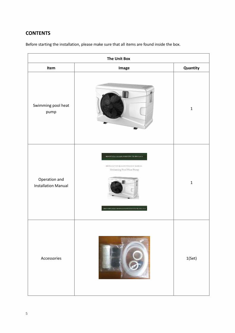
CONTENTS
Before starting the installation, please make sure that all items are found inside the box.
The Unit Box
Item Image Quantity
Swimming pool heat
pump
1
Operation and
Installation Manual
1
Accessories
1(Set)
6
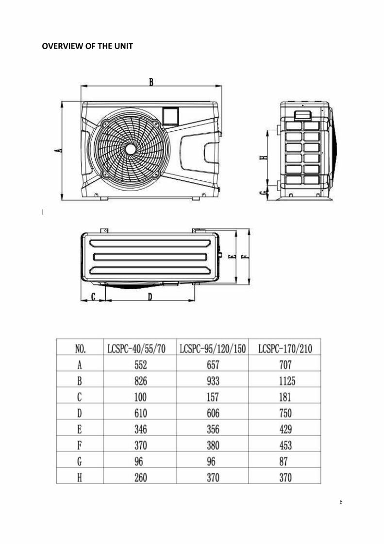
OVERVIEW OF THE UNIT
EXPLODED VIEW(ECO-30,55,70)
7
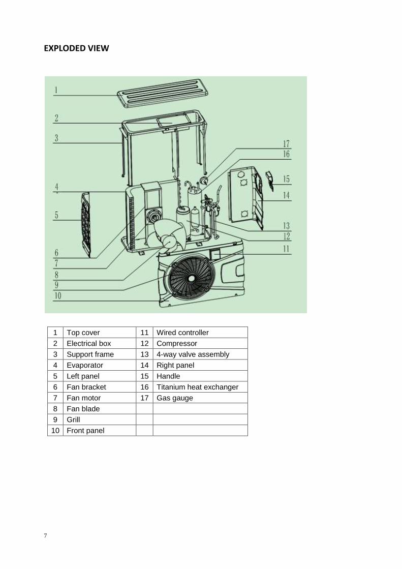
EXPLODED VIEW
1 Top cover 11 Wired controller
2 Electrical box 12 Compressor
3 Support frame 13 4-way valve assembly
4 Evaporator 14 Right panel
5 Left panel 15 Handle
6 Fan bracket 16 Titanium heat exchanger
7 Fan motor 17 Gas gauge
8 Fan blade
9 Grill
10 Front panel
8
INSTALLATION Installation guidelines The following information is for guidance only.
Locating the Unit The unit should be located on a solid, flat, horizontal surface. Ensure 3 meters of free air flow to the
discharge panel and 1 meter to the inlet panel. Ensure adequate access to the controller and for
maintenance purposes.
Precautions
-Avoid locating the unit close to bedrooms or other noise sensitive areas.
-Avoid a location which could create vibration i.e. secured to a solid wall.
-Try to avoid placing the unit under a tree or exposed to extreme conditions.
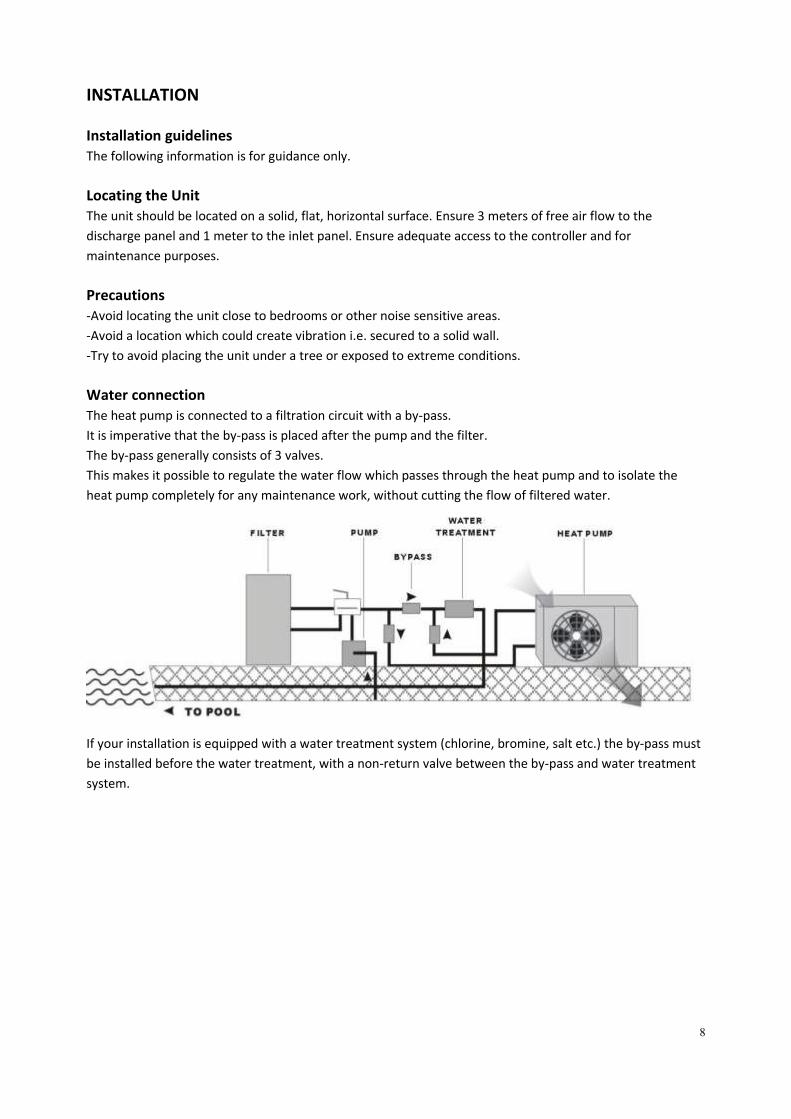
Water connection The heat pump is connected to a filtration circuit with a by-pass.
It is imperative that the by-pass is placed after the pump and the filter.
The by-pass generally consists of 3 valves.
This makes it possible to regulate the water flow which passes through the heat pump and to isolate the
heat pump completely for any maintenance work, without cutting the flow of filtered water.
If your installation is equipped with a water treatment system (chlorine, bromine, salt etc.) the by-pass must
be installed before the water treatment, with a non-return valve between the by-pass and water treatment
system.
9
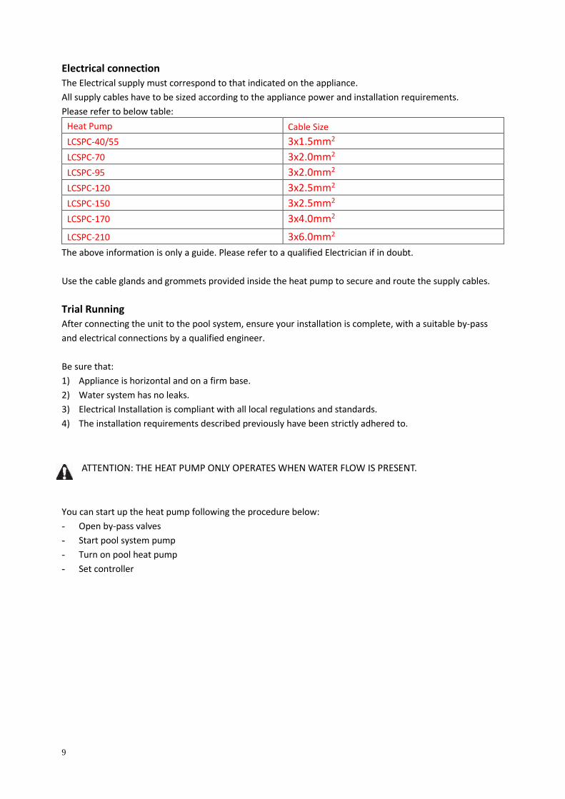
Electrical connection
The Electrical supply must correspond to that indicated on the appliance.
All supply cables have to be sized according to the appliance power and installation requirements.
Please refer to below table:
Heat Pump Cable Size
LCSPC-40/55 3x1.5mm2
LCSPC-70 3x2.0mm2
LCSPC-95 3x2.0mm2
LCSPC-120 3x2.5mm2
LCSPC-150 3x2.5mm2
LCSPC-170 3x4.0mm2
LCSPC-210 3x6.0mm2
The above information is only a guide. Please refer to a qualified Electrician if in doubt.
Use the cable glands and grommets provided inside the heat pump to secure and route the supply cables.
Trial Running After connecting the unit to the pool system, ensure your installation is complete, with a suitable by-pass
and electrical connections by a qualified engineer.
Be sure that:
1) Appliance is horizontal and on a firm base.
2) Water system has no leaks.
3) Electrical Installation is compliant with all local regulations and standards.
4) The installation requirements described previously have been strictly adhered to.
ATTENTION: THE HEAT PUMP ONLY OPERATES WHEN WATER FLOW IS PRESENT.
You can start up the heat pump following the procedure below:
- Open by-pass valves
- Start pool system pump
- Turn on pool heat pump
- Set controller

10
Easy control (Touch & GO)
1. Turn ON/OFF
(1) Turn ON: When the heat pump is OFF, press “ ” to turn on the heat pump.
OFF mode ON mode
(2)Turn OFF: When the heat pump is ON,press “ ” to turn off the heat pump.
ON mode OFF mode
2. Temperature Setting
When the heat pump is on, press or to change temperature setting.
Initial state
Press “ “
Press “ “
For example
Press “ ”
Flash
11
OPERATING THE UNIT
This is achieved via the Digital Controller.
NEVER LET THE DIGITAL CONTROLLER GET WET. THIS MAY CAUSE AN ELECTRIC SHOCK OR FIRE.
NEVER PRESS THE BUTTONS OF THE DIGITAL CONTROLLER WITH A HARD, POINTED OBJECT.
THIS MAY DAMAGE THE DIGITAL CONTROLLER.
NEVER INSPECT OR SERVICE THE DIGITAL CONTROLLER YOURSELF. REFER TO A QUALIFIED SERVICE
ENGINEER.
Features and functions
Basic controller functions
The basic controller functions are:
➢ Turning the heat pump ‘ON’/’OFF’.
➢ 24-hour time clock.
➢ Timer ‘ON’ and timer ‘OFF’.
➢ Parameter adjustment
12
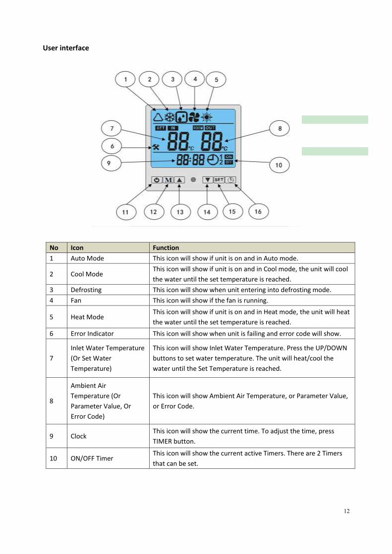
User interface
No Icon Function
1 Auto Mode This icon will show if unit is on and in Auto mode.
2 Cool Mode This icon will show if unit is on and in Cool mode, the unit will cool
the water until the set temperature is reached.
3 Defrosting This icon will show when unit entering into defrosting mode.
4 Fan This icon will show if the fan is running.
5 Heat Mode This icon will show if unit is on and in Heat mode, the unit will heat
the water until the set temperature is reached.
6 Error Indicator This icon will show when unit is failing and error code will show.
7
Inlet Water Temperature
(Or Set Water
Temperature)
This icon will show Inlet Water Temperature. Press the UP/DOWN
buttons to set water temperature. The unit will heat/cool the
water until the Set Temperature is reached.
8
Ambient Air
Temperature (Or
Parameter Value, Or
Error Code)
This icon will show Ambient Air Temperature, or Parameter Value,
or Error Code.
9 Clock This icon will show the current time. To adjust the time, press
TIMER button.
10 ON/OFF Timer This icon will show the current active Timers. There are 2 Timers
that can be set.

13
No Button Function
11 ON/OFF Press once to turn unit On or Off.
12 MODE To select unit running mode.
13 UP Press once to increase set temperature by 1℃, or increase parameter data
by 1 unit.
14 DOWN Press once to decrease set temperature by 1℃, or decrease parameter data
by 1 unit.
15 SET
These are the multi-purpose buttons. Combining with the "UP/DOWN" and
"MODE" and "TIMER" buttons, they are used for parameter setting,
parameter checking, and adjustment of the TIMER.
16 TIMER To set CLOCK and TIMER.
Buttons
1. Unit ON/OFF button
Press this button when the unit is in standby mode. The unit can be turned ‘ON’ and run on the
setting mode. The running mode, temperatures, timer setting and clock times are displayed on the
screen.
NOTES: HAS A STARTUP DELAY, PLEASE WAIT FOR 3 MINUTES.
Press this button again when the unit is running and the unit will then be turned ‘OFF’.
2. Mode button
Press this button to select the running mode at any point. Each time this button is pressed, the
mode will change in the sequence below:
NOTES:
1. Parameter 13: Unit mode selection decides heat pump running mode. When set at “0”, the
heat pump is in cooling mode, and if set at “1”,3 modes are available: Auto, Cooling, Heating.
If set at “2”, only heating is available.
3. And adjust buttons
These are the multi-purpose buttons. Combining with the and and buttons, they
are used for parameter setting, parameter checking, and timer adjustment.
On main running interface, press to set pool water temperature.
Heating
风
风
Cooling
风
风
Auto
14
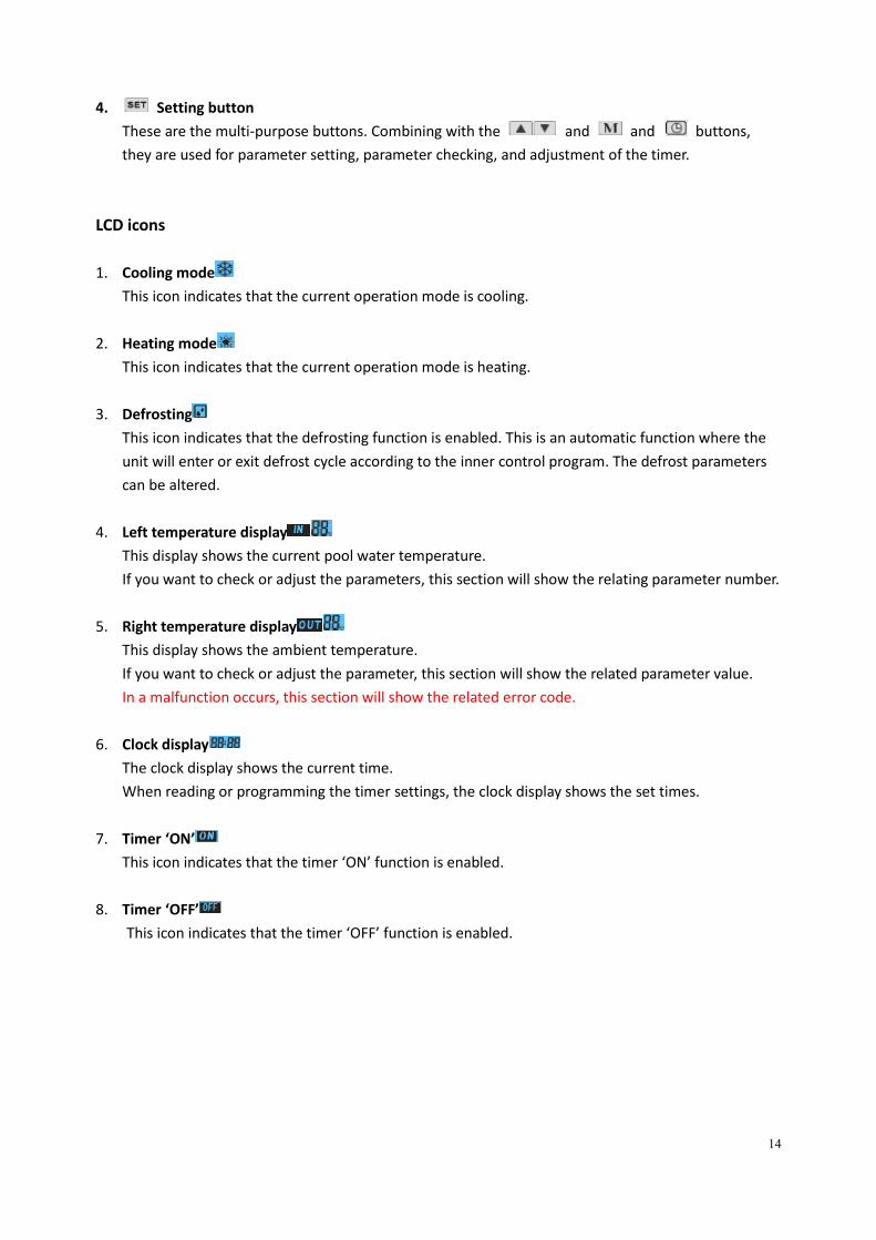
4. Setting button
These are the multi-purpose buttons. Combining with the and and buttons,
they are used for parameter setting, parameter checking, and adjustment of the timer.
LCD icons
1. Cooling mode
This icon indicates that the current operation mode is cooling.
2. Heating mode
This icon indicates that the current operation mode is heating.
3. Defrosting
This icon indicates that the defrosting function is enabled. This is an automatic function where the
unit will enter or exit defrost cycle according to the inner control program. The defrost parameters
can be altered.
4. Left temperature display
This display shows the current pool water temperature.
If you want to check or adjust the parameters, this section will show the relating parameter number.
5. Right temperature display
This display shows the ambient temperature.
If you want to check or adjust the parameter, this section will show the related parameter value.
In a malfunction occurs, this section will show the related error code.
6. Clock display
The clock display shows the current time.
When reading or programming the timer settings, the clock display shows the set times.
7. Timer ‘ON’
This icon indicates that the timer ‘ON’ function is enabled.
8. Timer ‘OFF’
This icon indicates that the timer ‘OFF’ function is enabled.
15
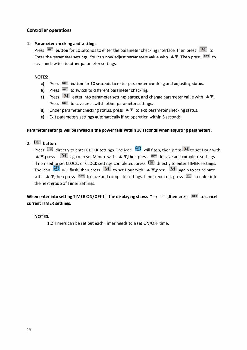
Controller operations
1. Parameter checking and setting.
Press button for 10 seconds to enter the parameter checking interface, then press to
Enter the parameter settings. You can now adjust parameters value with . Then press to
save and switch to other parameter settings.
NOTES:
a) Press button for 10 seconds to enter parameter checking and adjusting status.
b) Press to switch to different parameter checking.
c) Press enter into parameter settings status, and change parameter value with ,
Press to save and switch other parameter settings.
d) Under parameter checking status, press to exit parameter checking status.
e) Exit parameters settings automatically if no operation within 5 seconds.
Parameter settings will be invalid if the power fails within 10 seconds when adjusting parameters.
2. button
Press directly to enter CLOCK settings. The icon will flash, then press to set Hour with
,press again to set Minute with ,then press to save and complete settings.
If no need to set CLOCK, or CLOCK settings completed, press directly to enter TIMER settings.
The icon will flash, then press to set Hour with ,press again to set Minute
with ,then press to save and complete settings. If not required, press to enter into
the next group of Timer Settings.
When enter into setting TIMER ON/OFF till the displaying shows“--:--”,then press to cancel
current TIMER settings.
NOTES:
1.2 Timers can be set but each Timer needs to a set ON/OFF time.
16
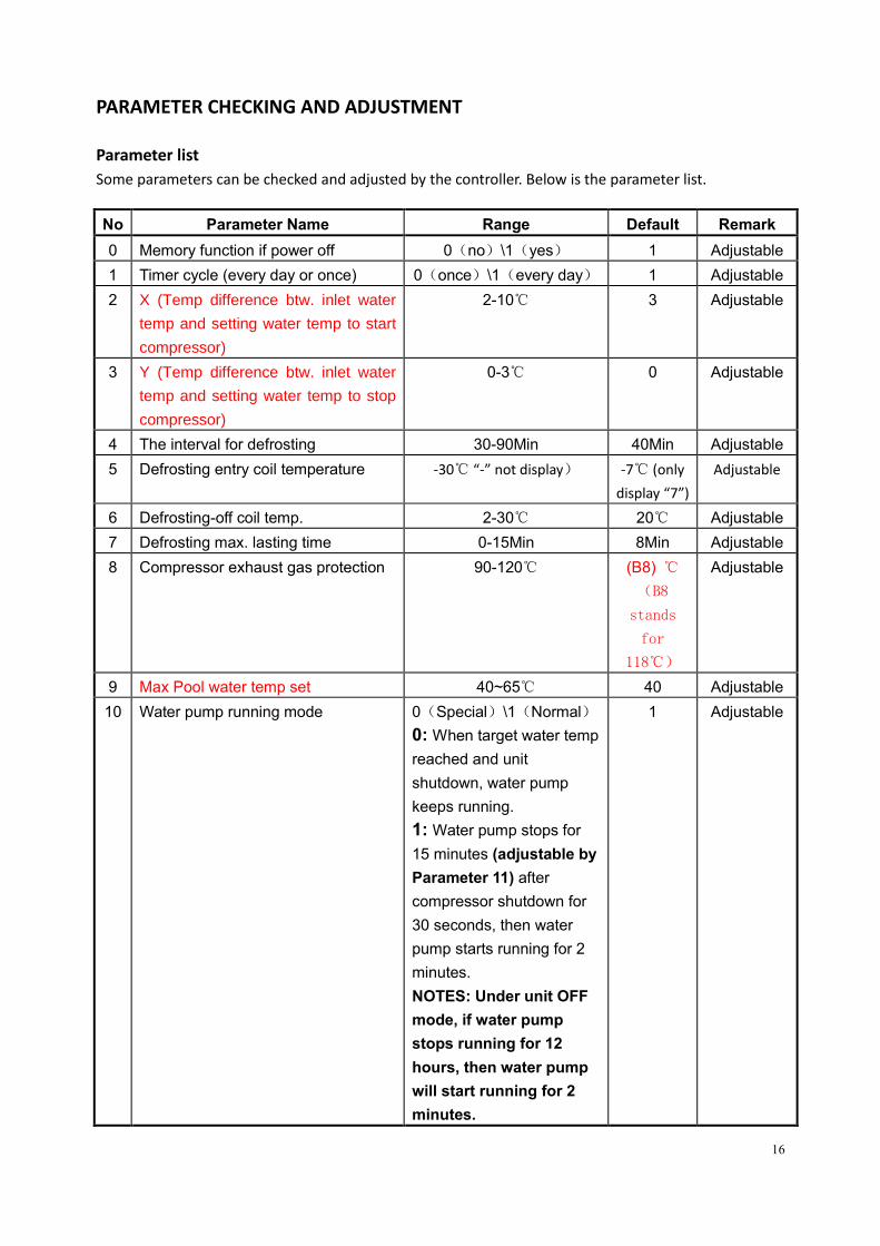
PARAMETER CHECKING AND ADJUSTMENT
Parameter list
Some parameters can be checked and adjusted by the controller. Below is the parameter list.
No Parameter Name Range Default Remark
0 Memory function if power off 0(no)\1(yes) 1 Adjustable
1 Timer cycle (every day or once) 0(once)\1(every day) 1 Adjustable
2 X (Temp difference btw. inlet water
temp and setting water temp to start
compressor)
2-10℃ 3 Adjustable
3 Y (Temp difference btw. inlet water
temp and setting water temp to stop
compressor)
0-3℃ 0 Adjustable
4 The interval for defrosting 30-90Min 40Min Adjustable
5 Defrosting entry coil temperature -30℃ “-” not display) -7℃ (only
display “7”)
Adjustable
6 Defrosting-off coil temp. 2-30℃ 20℃ Adjustable
7 Defrosting max. lasting time 0-15Min 8Min Adjustable
8 Compressor exhaust gas protection 90-120℃ (B8) ℃
(B8
stands
for
118℃)
Adjustable
9 Max Pool water temp set 40~65℃ 40 Adjustable
10 Water pump running mode 0(Special)\1(Normal)
0: When target water temp
reached and unit
shutdown, water pump
keeps running.
1: Water pump stops for
15 minutes (adjustable by
Parameter 11) after
compressor shutdown for
30 seconds, then water
pump starts running for 2
minutes.
NOTES: Under unit OFF
mode, if water pump
stops running for 12
hours, then water pump
will start running for 2
minutes.
1 Adjustable
17
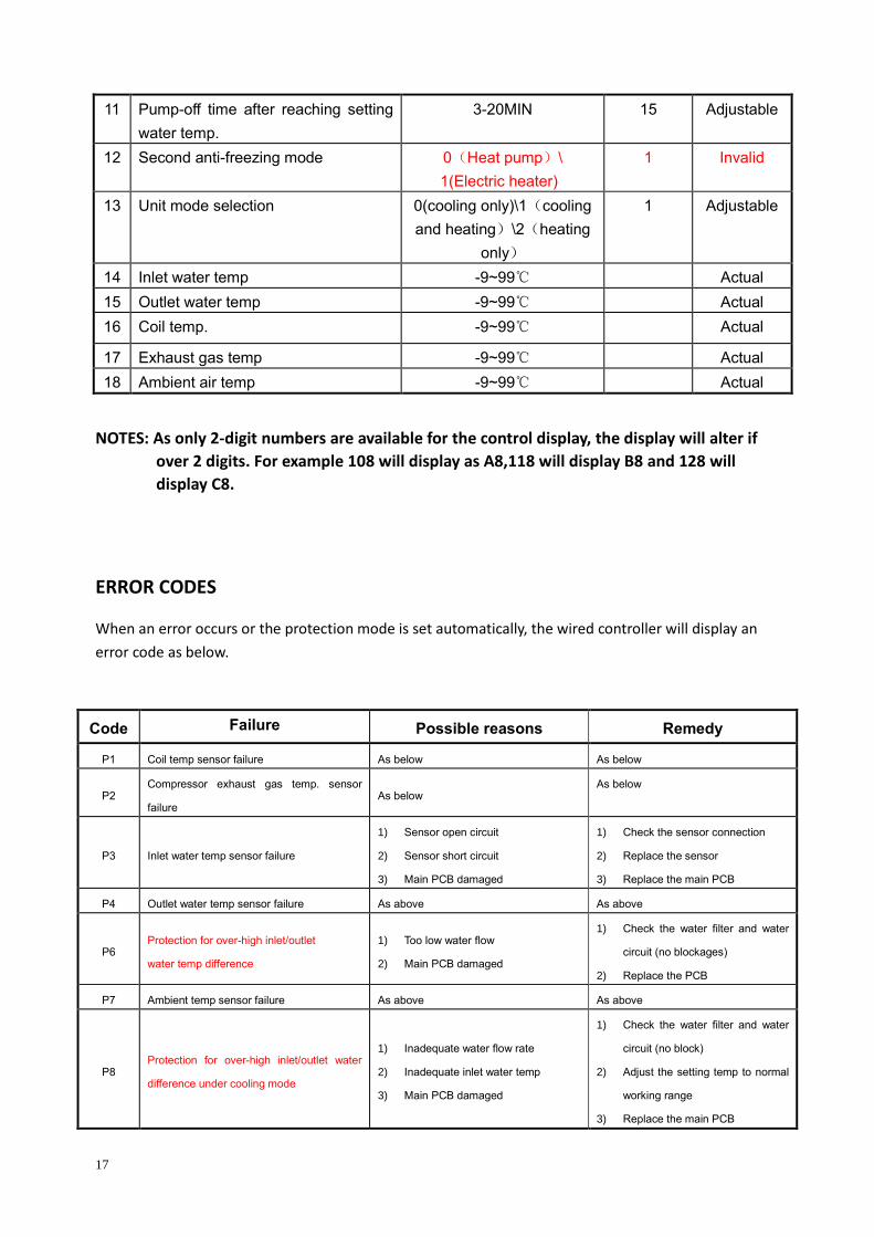
NOTES: As only 2-digit numbers are available for the control display, the display will alter if
over 2 digits. For example 108 will display as A8,118 will display B8 and 128 will
display C8.
ERROR CODES
When an error occurs or the protection mode is set automatically, the wired controller will display an
error code as below.
Code Failure Possible reasons Remedy
P1 Coil temp sensor failure As below As below
P2 Compressor exhaust gas temp. sensor
failure As below
As below
P3 Inlet water temp sensor failure
1) Sensor open circuit
2) Sensor short circuit
3) Main PCB damaged
1) Check the sensor connection
2) Replace the sensor
3) Replace the main PCB
P4 Outlet water temp sensor failure As above As above
P6 Protection for over-high inlet/outlet
water temp difference
1) Too low water flow
2) Main PCB damaged
1) Check the water filter and water
circuit (no blockages)
2) Replace the PCB
P7 Ambient temp sensor failure As above As above
P8 Protection for over-high inlet/outlet water
difference under cooling mode
1) Inadequate water flow rate
2) Inadequate inlet water temp
3) Main PCB damaged
1) Check the water filter and water
circuit (no block)
2) Adjust the setting temp to normal
working range
3) Replace the main PCB
11 Pump-off time after reaching setting
water temp.
3-20MIN 15 Adjustable
12 Second anti-freezing mode 0(Heat pump)\
1(Electric heater)
1 Invalid
13 Unit mode selection 0(cooling only)\1(cooling
and heating)\2(heating
only)
1 Adjustable
14 Inlet water temp -9~99℃ Actual
15 Outlet water temp -9~99℃ Actual
16 Coil temp. -9~99℃ Actual
17 Exhaust gas temp -9~99℃ Actual
18 Ambient air temp -9~99℃ Actual
18
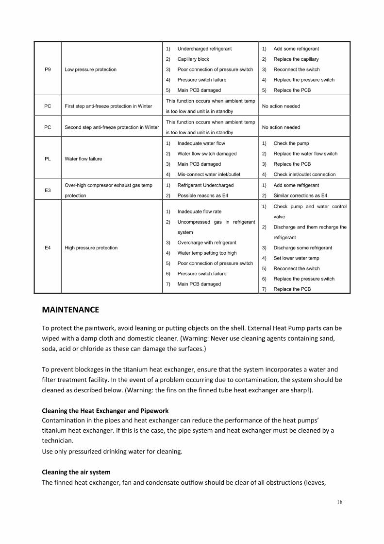
P9 Low pressure protection
1) Undercharged refrigerant
2) Capillary block
3) Poor connection of pressure switch
4) Pressure switch failure
5) Main PCB damaged
1) Add some refrigerant
2) Replace the capillary
3) Reconnect the switch
4) Replace the pressure switch
5) Replace the PCB
PC First step anti-freeze protection in Winter This function occurs when ambient temp
is too low and unit is in standby No action needed
PC Second step anti-freeze protection in Winter This function occurs when ambient temp
is too low and unit is in standby No action needed
PL Water flow failure
1) Inadequate water flow
2) Water flow switch damaged
3) Main PCB damaged
4) Mis-connect water inlet/outlet
1) Check the pump
2) Replace the water flow switch
3) Replace the PCB
4) Check inlet/outlet connection
E3 Over-high compressor exhaust gas temp
protection
1) Refrigerant Undercharged
2) Possible reasons as E4
1) Add some refrigerant
2) Similar corrections as E4
E4 High pressure protection
1) Inadequate flow rate
2) Uncompressed gas in refrigerant
system
3) Overcharge with refrigerant
4) Water temp setting too high
5) Poor connection of pressure switch
6) Pressure switch failure
7) Main PCB damaged
1) Check pump and water control
valve
2) Discharge and them recharge the
refrigerant
3) Discharge some refrigerant
4) Set lower water temp
5) Reconnect the switch
6) Replace the pressure switch
7) Replace the PCB
MAINTENANCE
To protect the paintwork, avoid leaning or putting objects on the shell. External Heat Pump parts can be
wiped with a damp cloth and domestic cleaner. (Warning: Never use cleaning agents containing sand,
soda, acid or chloride as these can damage the surfaces.)
To prevent blockages in the titanium heat exchanger, ensure that the system incorporates a water and
filter treatment facility. In the event of a problem occurring due to contamination, the system should be
cleaned as described below. (Warning: the fins on the finned tube heat exchanger are sharp!).
Cleaning the Heat Exchanger and Pipework
Contamination in the pipes and heat exchanger can reduce the performance of the heat pumps’
titanium heat exchanger. If this is the case, the pipe system and heat exchanger must be cleaned by a
technician.
Use only pressurized drinking water for cleaning.
Cleaning the air system
The finned heat exchanger, fan and condensate outflow should be clear of all obstructions (leaves,

19
twigs, etc.) before each new heating season. These can be manually removed using compressed air or
by flushing with clean water.
It may be necessary to remove the unit cover and air inlet grid first.
Attention: Before opening the unit, ensure that all electrical supplies are isolated.
To prevent the evaporator and the condensate tray from being damaged, do not use hard or sharp
objects for cleaning.
Under extreme weather conditions (e.g. snow drifts), ice may form on the air intake and exhaust air
outlet grids. If this happens, the ice must be removed in the vicinity of the air intake and exhaust air
outlet grids to ensure that the minimum air flow rate is maintained.
Winter Shutdown.
To prevent frost damage to the unit when not in use the Heat Pump should be drained of all water.
Failing this another form of frost protection should be considered and actioned.
Attention: The warranty does not cover damage caused by inadequate frost protection measures
during the winter.
TROUBLESHOOTING This section provides useful information for diagnosing and correcting certain problems which may
occur. Before starting the troubleshooting procedure, carry out a thorough visual inspection of the unit
and look for obvious defects such as loose connections or defective wiring.
Before contacting your local dealer, read this chapter carefully. It could save you time and money.
WHEN CARRYING OUT ANY MAINTENANCE ENSURE ADEQUATE PRECAUTIONS ARE TAKEN TO
PREVENT AN ELECTRIC SHOCK.
The hints below are for guidance only. If you cannot solve the problem, consult your installer/local
dealer.
The Heat pump will not run.
Please check:
➢ There is a supply voltage (tripped fuse, power failure).
➢ The switch on the wired controller is switched on, and whether the correct set point temperature
has been set.
The set temperature level cannot be reached.
Please check whether:
➢ The permissible operating conditions for the heat pump have been adhered to (air temperatures
too high or too low).
➢ The air inlet or outlet area is blocked, restricted or very dirty.
➢ There are closed valves or stop-cocks in the water pipes.
20
The timer works but the programmed actions are executed at the wrong time (e.g. 1 hour too late or
too early).
Please check whether:
➢ The clock and the day of the week are set correctly, adjust if necessary.
If you cannot correct the fault yourself, please contact your after-sales service technician.
Work on the heat pump may only be carried out by authorized and qualified after-sales service
technicians.
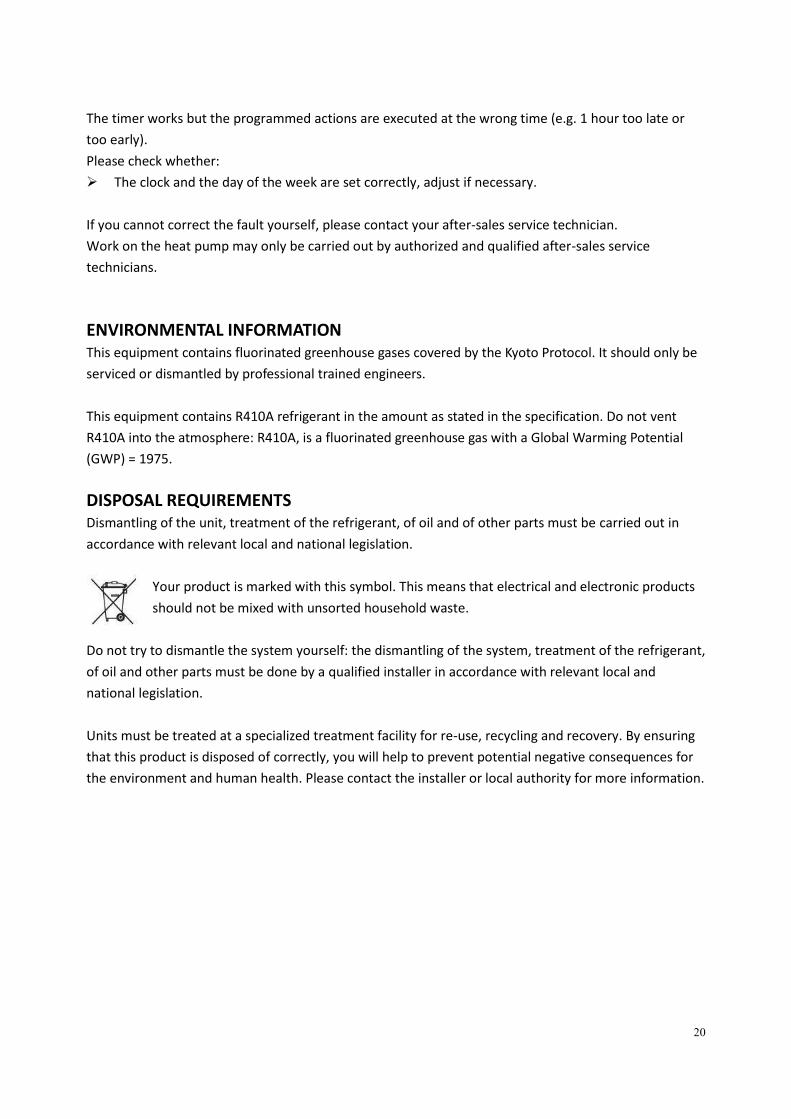
ENVIRONMENTAL INFORMATION This equipment contains fluorinated greenhouse gases covered by the Kyoto Protocol. It should only be
serviced or dismantled by professional trained engineers.
This equipment contains R410A refrigerant in the amount as stated in the specification. Do not vent
R410A into the atmosphere: R410A, is a fluorinated greenhouse gas with a Global Warming Potential
(GWP) = 1975.
DISPOSAL REQUIREMENTS Dismantling of the unit, treatment of the refrigerant, of oil and of other parts must be carried out in
accordance with relevant local and national legislation.
Your product is marked with this symbol. This means that electrical and electronic products
should not be mixed with unsorted household waste.
Do not try to dismantle the system yourself: the dismantling of the system, treatment of the refrigerant,
of oil and other parts must be done by a qualified installer in accordance with relevant local and
national legislation.
Units must be treated at a specialized treatment facility for re-use, recycling and recovery. By ensuring
that this product is disposed of correctly, you will help to prevent potential negative consequences for
the environment and human health. Please contact the installer or local authority for more information.
21
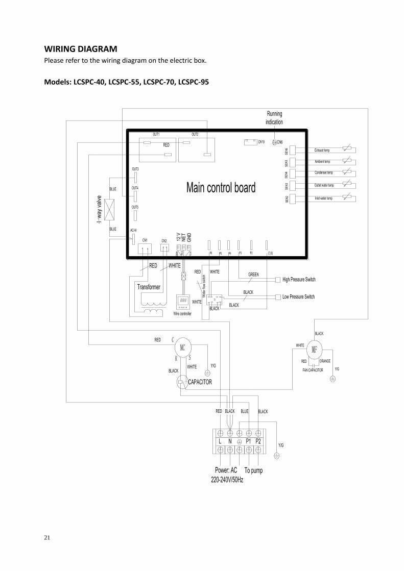
WIRING DIAGRAM Please refer to the wiring diagram on the electric box.
Models: LCSPC-40, LCSPC-55, LCSPC-70, LCSPC-95
22
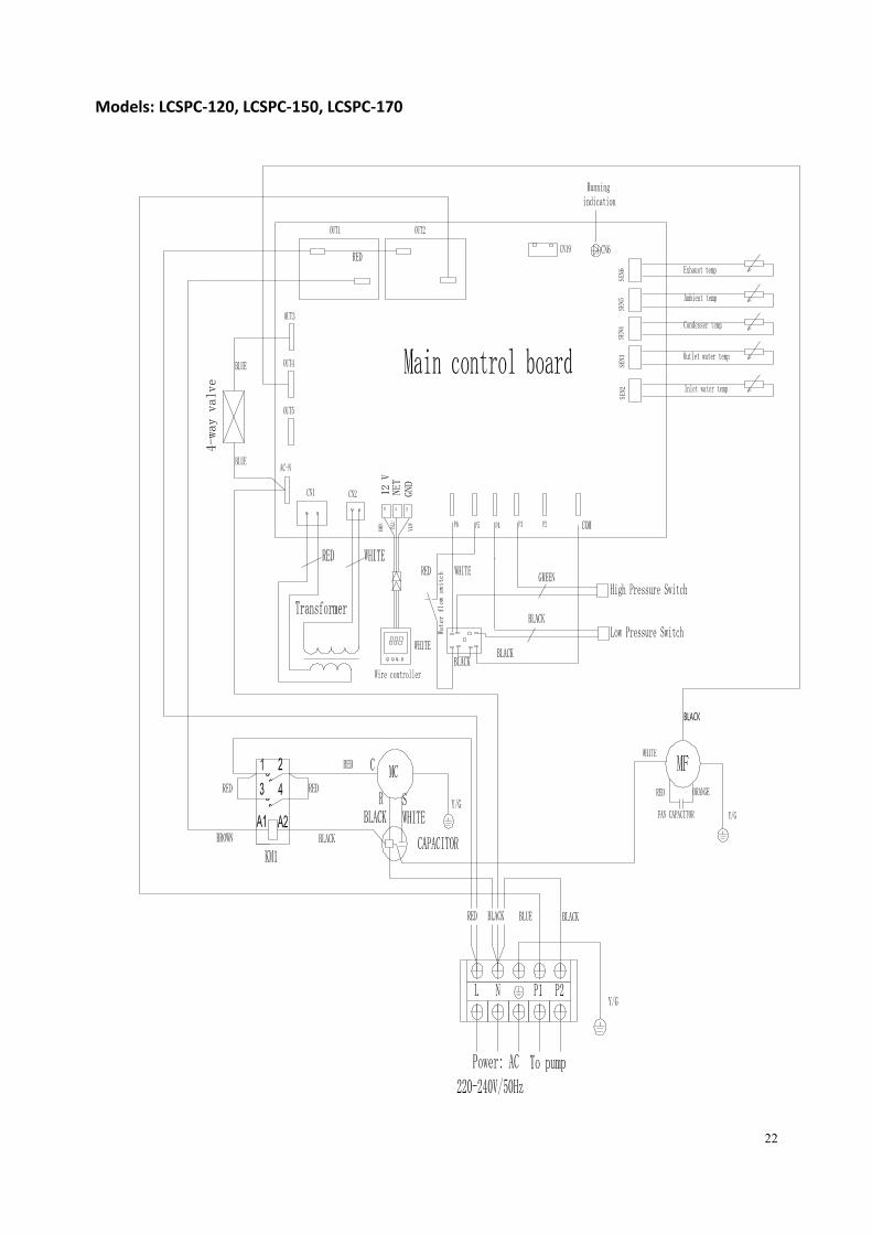
Models: LCSPC-120, LCSPC-150, LCSPC-170

23
Models: LCSPC-210
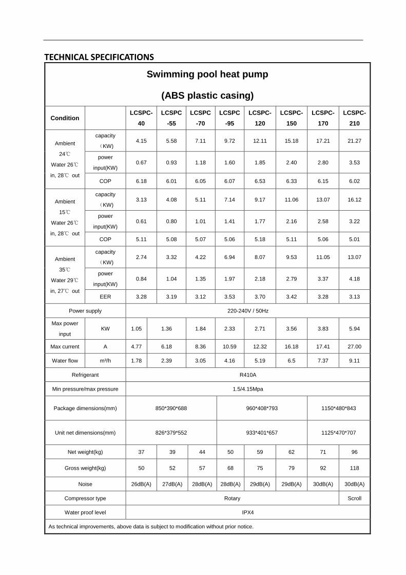
TECHNICAL SPECIFICATIONS
Swimming pool heat pump
(ABS plastic casing)
Condition LCSPC-
40
LCSPC
-55
LCSPC
-70
LCSPC
-95
LCSPC-
120
LCSPC-
150
LCSPC-
170
LCSPC-
210
Ambient
24℃
Water 26℃
in, 28℃ out
capacity
(KW) 4.15 5.58 7.11 9.72 12.11 15.18 17.21 21.27
power
input(KW) 0.67 0.93 1.18 1.60 1.85 2.40 2.80 3.53
COP 6.18 6.01 6.05 6.07 6.53 6.33 6.15 6.02
Ambient
15℃
Water 26℃
in, 28℃ out
capacity
(KW) 3.13 4.08 5.11 7.14 9.17 11.06 13.07 16.12
power
input(KW) 0.61 0.80 1.01 1.41 1.77 2.16 2.58 3.22
COP 5.11 5.08 5.07 5.06 5.18 5.11 5.06 5.01
Ambient
35℃
Water 29℃
in, 27℃ out
capacity
(KW) 2.74 3.32 4.22 6.94 8.07 9.53 11.05 13.07
power
input(KW) 0.84 1.04 1.35 1.97 2.18 2.79 3.37 4.18
EER 3.28 3.19 3.12 3.53 3.70 3.42 3.28 3.13
Power supply 220-240V / 50Hz
Max power
input KW 1.05 1.36 1.84 2.33 2.71 3.56 3.83 5.94
Max current A 4.77 6.18 8.36 10.59 12.32 16.18 17.41 27.00
Water flow m³/h 1.78 2.39 3.05 4.16 5.19 6.5 7.37 9.11
Refrigerant R410A
Min pressure/max pressure 1.5/4.15Mpa
Package dimensions(mm) 850*390*688 960*408*793 1150*480*843
Unit net dimensions(mm) 826*379*552 933*401*657 1125*470*707
Net weight(kg) 37 39 44 50 59 62 71 96
Gross weight(kg) 50 52 57 68 75 79 92 118
Noise 26dB(A) 27dB(A) 28dB(A) 28dB(A) 29dB(A) 29dB(A) 30dB(A) 30dB(A)
Compressor type Rotary Scroll
Water proof level IPX4
As technical improvements, above data is subject to modification without prior notice.
1
Contact details
HeatPumps4Pools Ltd
Rosemary Lodge
Church Road
Ramsden Bellhouse
Essex
CM11 1RT
United Kingdom
Tel +44 1268 206560
www.HeatPumps4Pools.com