table of contents - colorado4wheel.com 2005 transmission...table of contents - continued 7.0 ......
TRANSCRIPT

TABLE OF CONTENTS
1.0 INTRODUCTION . . . . . . . . . . . . . . . . . . . . . . . . . . . . . . . . . . . . . . . . . . . . . . . . . . . . . . . . .1
1.1 SYSTEM COVERAGE . . . . . . . . . . . . . . . . . . . . . . . . . . . . . . . . . . . . . . . . . . . . . . .11.2 SIX-STEP TROUBLESHOOTING PROCEDURE . . . . . . . . . . . . . . . . . . . . . . . . . .1
2.0 IDENTIFICATION OF SYSTEM . . . . . . . . . . . . . . . . . . . . . . . . . . . . . . . . . . . . . . . . . . . . .1
3.0 SYSTEM DESCRIPTION AND FUNCTIONAL OPERATION . . . . . . . . . . . . . . . . . . . . . .1
3.1 GENERAL DESCRIPTION . . . . . . . . . . . . . . . . . . . . . . . . . . . . . . . . . . . . . . . . . . . .13.2 FUNCTIONAL OPERATION . . . . . . . . . . . . . . . . . . . . . . . . . . . . . . . . . . . . . . . . . . .2
3.2.1 TRANSMISSION OPERATION AND SHIFT SCHEDULING ATVARIOUS OIL TEMPERATURES . . . . . . . . . . . . . . . . . . . . . . . . . . . . . . .2
3.2.3 DRIVE LEARN PROCEDURE – 45/545RFE . . . . . . . . . . . . . . . . . . . . . .33.3 DIAGNOSTIC TROUBLE CODES . . . . . . . . . . . . . . . . . . . . . . . . . . . . . . . . . . . . . .5
3.3.1 HARD CODE . . . . . . . . . . . . . . . . . . . . . . . . . . . . . . . . . . . . . . . . . . . . . . .53.3.2 ONE TRIP FAILURES. . . . . . . . . . . . . . . . . . . . . . . . . . . . . . . . . . . . . . . .53.3.3 INTERMITTENT CODE. . . . . . . . . . . . . . . . . . . . . . . . . . . . . . . . . . . . . . .53.3.4 STARTS SINCE SET COUNTER. . . . . . . . . . . . . . . . . . . . . . . . . . . . . . .53.3.5 TROUBLE CODE ERASURE . . . . . . . . . . . . . . . . . . . . . . . . . . . . . . . . . .63.3.6 QUICK LEARN . . . . . . . . . . . . . . . . . . . . . . . . . . . . . . . . . . . . . . . . . . . . .63.3.7 CLUTCH VOLUMES – 45/545RFE. . . . . . . . . . . . . . . . . . . . . . . . . . . . . .73.3.8 EATX DTC EVENT DATA . . . . . . . . . . . . . . . . . . . . . . . . . . . . . . . . . . . . .7
3.4 USING THE DRBIIIT . . . . . . . . . . . . . . . . . . . . . . . . . . . . . . . . . . . . . . . . . . . . . . . . .73.5 DRBIIIT ERROR MESSAGES . . . . . . . . . . . . . . . . . . . . . . . . . . . . . . . . . . . . . . . . .7
3.5.1 DRBIIIT DOES NOT POWER UP (BLANK SCREEN). . . . . . . . . . . . . . .73.5.2 DISPLAY IS NOT VISIBLE . . . . . . . . . . . . . . . . . . . . . . . . . . . . . . . . . . . .83.5.3 SOME DISPLAY ITEMS READ ‘‘---’’ . . . . . . . . . . . . . . . . . . . . . . . . . . . .8
3.6 TRANSMISSION SIMULATOR (MILLER TOOL #8333) AND ELECTRONICTRANSMISSION ADAPTER KIT (MILLER TOOL #8333-1A) . . . . . . . . . . . . . . . 8
4.0 DISCLAIMERS, SAFETY, AND WARNINGS . . . . . . . . . . . . . . . . . . . . . . . . . . . . . . . . . .8
4.1 DISCLAIMERS. . . . . . . . . . . . . . . . . . . . . . . . . . . . . . . . . . . . . . . . . . . . . . . . . . . . . .84.2 SAFETY . . . . . . . . . . . . . . . . . . . . . . . . . . . . . . . . . . . . . . . . . . . . . . . . . . . . . . . . . . .8
4.2.1 TECHNICIAN SAFETY INFORMATION . . . . . . . . . . . . . . . . . . . . . . . . . .84.2.2 VEHICLE PREPARATION FOR TESTING. . . . . . . . . . . . . . . . . . . . . . . .94.2.3 SERVICING SUB-ASSEMBLIES . . . . . . . . . . . . . . . . . . . . . . . . . . . . . . .94.2.4 DRBIIIT SAFETY INFORMATION. . . . . . . . . . . . . . . . . . . . . . . . . . . . . . .9
4.3 WARNINGS . . . . . . . . . . . . . . . . . . . . . . . . . . . . . . . . . . . . . . . . . . . . . . . . . . . . . . . .94.3.1 VEHICLE DAMAGE WARNINGS . . . . . . . . . . . . . . . . . . . . . . . . . . . . . . .94.3.2 ROAD TESTING A COMPLAINT VEHICLE . . . . . . . . . . . . . . . . . . . . . . .94.3.3 ELECTRONIC PINION FACTOR WARNINGS (IF APPLICABLE) . . . .10
4.4 BULLETINS AND RECALLS. . . . . . . . . . . . . . . . . . . . . . . . . . . . . . . . . . . . . . . . . .10
5.0 REQUIRED TOOLS AND EQUIPMENT . . . . . . . . . . . . . . . . . . . . . . . . . . . . . . . . . . . . .10
6.0 GLOSSARY OF TERMS . . . . . . . . . . . . . . . . . . . . . . . . . . . . . . . . . . . . . . . . . . . . . . . . . .10
6.2 DEFINITIONS . . . . . . . . . . . . . . . . . . . . . . . . . . . . . . . . . . . . . . . . . . . . . . . . . . . . .11
i

TABLE OF CONTENTS - Continued
7.0 DIAGNOSTIC INFORMATION AND PROCEDURES . . . . . . . . . . . . . . . . . . . . . . . . . .13
COMMUNICATION*NO RESPONSE FROM TRANSMISSION CONTROL MODULE (DIESEL ONLY) . . .14
TRANSMISSION - RFEP0122-TPS/APPS LOW - DIESEL . . . . . . . . . . . . . . . . . . . . . . . . . . . . . . . . . . . . . . . . . .17P0123-TPS/APPS HIGH - DIESEL. . . . . . . . . . . . . . . . . . . . . . . . . . . . . . . . . . . . . . . . . .21P0124-TPS/APPS INTERMITTENT - DIESEL. . . . . . . . . . . . . . . . . . . . . . . . . . . . . . . . .25P0218-HIGH TEMPERATURE OPERATION ACTIVATED . . . . . . . . . . . . . . . . . . . . . . .27P0604-INTERNAL TCM . . . . . . . . . . . . . . . . . . . . . . . . . . . . . . . . . . . . . . . . . . . . . . . . . .29P0605-INTERNAL TCM . . . . . . . . . . . . . . . . . . . . . . . . . . . . . . . . . . . . . . . . . . . . . . . . . .30P0613-INTERNAL TCM . . . . . . . . . . . . . . . . . . . . . . . . . . . . . . . . . . . . . . . . . . . . . . . . . .31P0706-CHECK SHIFTER SIGNAL . . . . . . . . . . . . . . . . . . . . . . . . . . . . . . . . . . . . . . . . . .32P0711-TRANSMISSION TEMPERATURE SENSOR PERFORMANCE. . . . . . . . . . . . .39P0712-TRANSMISSION TEMPERATURE SENSOR LOW. . . . . . . . . . . . . . . . . . . . . . .42P0713-TRANSMISSION TEMPERATURE SENSOR HIGH . . . . . . . . . . . . . . . . . . . . . .45P0714-TRANSMISSION TEMPERATURE SENSOR INTERMITTENT . . . . . . . . . . . . .48P0715-INPUT SPEED SENSOR ERROR . . . . . . . . . . . . . . . . . . . . . . . . . . . . . . . . . . . .50P0720-OUTPUT SPEED SENSOR ERROR . . . . . . . . . . . . . . . . . . . . . . . . . . . . . . . . . .54P0725-ENGINE SPEED SENSOR CIRCUIT - DIESEL . . . . . . . . . . . . . . . . . . . . . . . . .58P0731-GEAR RATIO ERROR IN 1ST . . . . . . . . . . . . . . . . . . . . . . . . . . . . . . . . . . . . . . .61P0732-GEAR RATIO ERROR IN 2ND . . . . . . . . . . . . . . . . . . . . . . . . . . . . . . . . . . . . . . .64P0733-GEAR RATIO ERROR IN 3RD . . . . . . . . . . . . . . . . . . . . . . . . . . . . . . . . . . . . . . .67P0734-GEAR RATIO ERROR IN 4TH . . . . . . . . . . . . . . . . . . . . . . . . . . . . . . . . . . . . . . .70P0735-GEAR RATIO ERROR 4TH PRIME . . . . . . . . . . . . . . . . . . . . . . . . . . . . . . . . . . .72P0736-GEAR RATIO ERROR IN REVERSE. . . . . . . . . . . . . . . . . . . . . . . . . . . . . . . . . .74P0740-TCC OUT OF RANGE. . . . . . . . . . . . . . . . . . . . . . . . . . . . . . . . . . . . . . . . . . . . . .76P0750-LR SOLENOID CIRCUIT. . . . . . . . . . . . . . . . . . . . . . . . . . . . . . . . . . . . . . . . . . . .78P0755-2C SOLENOID CIRCUIT. . . . . . . . . . . . . . . . . . . . . . . . . . . . . . . . . . . . . . . . . . . .82P0760-OD SOLENOID CIRCUIT . . . . . . . . . . . . . . . . . . . . . . . . . . . . . . . . . . . . . . . . . . .86P0765-UD SOLENOID CIRCUIT . . . . . . . . . . . . . . . . . . . . . . . . . . . . . . . . . . . . . . . . . . .90P0770-4C SOLENOID CIRCUIT. . . . . . . . . . . . . . . . . . . . . . . . . . . . . . . . . . . . . . . . . . . .94P0841-LR PRESSURE SWITCH SENSE CIRCUIT . . . . . . . . . . . . . . . . . . . . . . . . . . . .98P0845-2C HYDRAULIC PRESSURE TEST FAILURE . . . . . . . . . . . . . . . . . . . . . . . . .102P0846-2C PRESSURE SWITCH SENSE CIRCUIT . . . . . . . . . . . . . . . . . . . . . . . . . . .108P0868-LINE PRESSURE LOW. . . . . . . . . . . . . . . . . . . . . . . . . . . . . . . . . . . . . . . . . . . .112P0869-LINE PRESSURE HIGH . . . . . . . . . . . . . . . . . . . . . . . . . . . . . . . . . . . . . . . . . . .117P0870-OD HYDRAULIC PRESSURE TEST FAILURE . . . . . . . . . . . . . . . . . . . . . . . . .122P0871-OD PRESSURE SWITCH SENSE CIRCUIT . . . . . . . . . . . . . . . . . . . . . . . . . . .128P0875-UD HYDRAULIC PRESSURE TEST FAILURE . . . . . . . . . . . . . . . . . . . . . . . . .132P0876-UD PRESSURE SWITCH SENSE CIRCUIT . . . . . . . . . . . . . . . . . . . . . . . . . . .138P0884-POWER UP AT SPEED . . . . . . . . . . . . . . . . . . . . . . . . . . . . . . . . . . . . . . . . . . .142P0888-RELAY OUTPUT ALWAYS OFF . . . . . . . . . . . . . . . . . . . . . . . . . . . . . . . . . . . . .143P0890-SWITCHED BATTERY . . . . . . . . . . . . . . . . . . . . . . . . . . . . . . . . . . . . . . . . . . . .147P0891-TRANSMISSION RELAY ALWAYS ON . . . . . . . . . . . . . . . . . . . . . . . . . . . . . . .149P0932-LINE PRESSURE SENSOR CIRCUIT FAULT. . . . . . . . . . . . . . . . . . . . . . . . . .152P0934-LINE PRESSURE SENSOR LOW . . . . . . . . . . . . . . . . . . . . . . . . . . . . . . . . . . .155P0935-LINE PRESSURE SENSOR HIGH. . . . . . . . . . . . . . . . . . . . . . . . . . . . . . . . . . .158P0944-LOSS OF PRIME. . . . . . . . . . . . . . . . . . . . . . . . . . . . . . . . . . . . . . . . . . . . . . . . .161P0987-4C HYDRAULIC PRESSURE TEST FAILURE . . . . . . . . . . . . . . . . . . . . . . . . .164P0988-4C PRESSURE SWITCH SENSE CIRCUIT . . . . . . . . . . . . . . . . . . . . . . . . . . .170P1684-BATTERY WAS DISCONNECTED . . . . . . . . . . . . . . . . . . . . . . . . . . . . . . . . . . .174
ii
TABLE OF CONTENTS - Continued
P1694-BUS COMMUNICATION WITH ENGINE MODULE. . . . . . . . . . . . . . . . . . . . . .176P1715-RESTRICTED PORT IN T3 RANGE . . . . . . . . . . . . . . . . . . . . . . . . . . . . . . . . .178P1736-GEAR RATIO ERROR IN 2ND PRIME . . . . . . . . . . . . . . . . . . . . . . . . . . . . . . .180P1775-SOLENOID SWITCH VALVE LATCHED IN TCC POSITION . . . . . . . . . . . . . .182P1776-SOLENOID SWITCH VALVE LATCHED IN LR POSITION. . . . . . . . . . . . . . . .186P1790-FAULT IMMEDIATELY AFTER SHIFT . . . . . . . . . . . . . . . . . . . . . . . . . . . . . . . .190P1793-TRD LINK COMMUNICATION ERROR . . . . . . . . . . . . . . . . . . . . . . . . . . . . . . .191P1794-SPEED SENSOR GROUND ERROR . . . . . . . . . . . . . . . . . . . . . . . . . . . . . . . .194P2700-INADEQUATE ELEMENT VOLUME LR. . . . . . . . . . . . . . . . . . . . . . . . . . . . . . .197P2701-INADEQUATE ELEMENT VOLUME 2C. . . . . . . . . . . . . . . . . . . . . . . . . . . . . . .199P2702-INADEQUATE ELEMENT VOLUME OD . . . . . . . . . . . . . . . . . . . . . . . . . . . . . .201P2703- INADEQUATE ELEMENT VOLUME UD . . . . . . . . . . . . . . . . . . . . . . . . . . . . . .203P2704-INADEQUATE ELEMENT VOLUME 4C. . . . . . . . . . . . . . . . . . . . . . . . . . . . . . .205P2706-MS SOLENOID CIRCUIT . . . . . . . . . . . . . . . . . . . . . . . . . . . . . . . . . . . . . . . . . .207*BACKUP LAMPS COME ON WHILE SHIFTER IS NOT IN REVERSE POSITION. .211*BACKUP LAMPS INOPERATIVE . . . . . . . . . . . . . . . . . . . . . . . . . . . . . . . . . . . . . . . . .212*BUMP FELT SHORTLY AFTER STOP WITH NO DTC’S PRESENT . . . . . . . . . . . . .214*BUMP FELT WHILE COASTING IN NEUTRAL WITH NO DTC’S PRESENT . . . . . .215*CHECKING PARK/NEUTRAL SWITCH OPERATION . . . . . . . . . . . . . . . . . . . . . . . . .216*POOR SHIFT QUALITY . . . . . . . . . . . . . . . . . . . . . . . . . . . . . . . . . . . . . . . . . . . . . . . .218*TRANSMISSION NOISY WITH NO DTC’S PRESENT . . . . . . . . . . . . . . . . . . . . . . . .219*TRANSMISSION SHIFTS EARLY WITH NO DTC’S . . . . . . . . . . . . . . . . . . . . . . . . . .221*TRANSMISSION SHIFTS ROUGH AFTER TCM REPLACEMENT OR REFLASH . .222*TRANSMISSION SIMULATOR WILL NOT POWER UP . . . . . . . . . . . . . . . . . . . . . . .223*VEHICLE IS SLUGGISH WITH NO DTC’S PRESENT . . . . . . . . . . . . . . . . . . . . . . . .224
VERIFICATION TESTSVERIFICATION TESTS. . . . . . . . . . . . . . . . . . . . . . . . . . . . . . . . . . . . . . . . . . . . . . . . . .225
8.0 COMPONENT LOCATIONS . . . . . . . . . . . . . . . . . . . . . . . . . . . . . . . . . . . . . . . . . . . . . .227
8.1 ENGINE CONTROL MODULE LOCATIONS. . . . . . . . . . . . . . . . . . . . . . . . . . . .2278.2 TRANSMISSION CONTROL MODULE LOCATIONS . . . . . . . . . . . . . . . . . . . . .2278.3 TRANSMISSION COMPONENT LOCATIONS . . . . . . . . . . . . . . . . . . . . . . . . . .2278.4 TRANSMISSION LINE PRESSURE SENSOR . . . . . . . . . . . . . . . . . . . . . . . . . .228
9.0 CONNECTOR PINOUTS . . . . . . . . . . . . . . . . . . . . . . . . . . . . . . . . . . . . . . . . . . . . . . . .229
DATA LINK CONNECTOR - BLACK 16 WAY . . . . . . . . . . . . . . . . . . . . . . . . . . . . . . . .229INPUT SPEED SENSOR (A/T) - BLACK 2 WAY. . . . . . . . . . . . . . . . . . . . . . . . . . . . . .229LINE PRESSURE SENSOR (2.8L 45RFE) - BLACK 4 WAY . . . . . . . . . . . . . . . . . . . .229OUTPUT SPEED SENSOR (A/T) - BLACK 2 WAY. . . . . . . . . . . . . . . . . . . . . . . . . . . .230FUSES (GAS) . . . . . . . . . . . . . . . . . . . . . . . . . . . . . . . . . . . . . . . . . . . . . . . . . . . . . . . . .232TRANSMISSION CONTROL RELAY (A/T) . . . . . . . . . . . . . . . . . . . . . . . . . . . . . . . . . .232POWERTRAIN CONTROL MODULE C4 (3.7L A/T) - BLACK/GREEN 38 WAY . . . . .233TRANSMISSION CONTROL MODULE (2.8L) - BLACK 60 WAY. . . . . . . . . . . . . . . . .234TRANSMISSION RANGE SENSOR (42RLE) - 10 WAY. . . . . . . . . . . . . . . . . . . . . . . .235TRANSMISSION SOLENOID/PRESSURE SWITCH ASSEMBLY (42RLE) - 10WAY . . . . . . . . . . . . . . . . . . . . . . . . . . . . . . . . . . . . . . . . . . . . . . . . . . . . . . . . . . . . . . . . .235TRANSMISSION SOLENOID/TRS ASSEMBLY (2.8L 45RFE) - GRAY 23 WAY . . . . .235
10.0 SCHEMATIC DIAGRAMS . . . . . . . . . . . . . . . . . . . . . . . . . . . . . . . . . . . . . . . . . . . . . . . .237
10.1 DIESEL . . . . . . . . . . . . . . . . . . . . . . . . . . . . . . . . . . . . . . . . . . . . . . . . . . . . . . . . .237
iii

TABLE OF CONTENTS - Continued
11.0 CHARTS AND GRAPHS . . . . . . . . . . . . . . . . . . . . . . . . . . . . . . . . . . . . . . . . . . . . . . . .239
11.1 PRESSURE SWITCH STATES . . . . . . . . . . . . . . . . . . . . . . . . . . . . . . . . . . . . . .23911.2 SHIFT LEVER ERROR CODES. . . . . . . . . . . . . . . . . . . . . . . . . . . . . . . . . . . . . .23911.3 TRANSMISSION RANGE SENSOR SWITCH STATES . . . . . . . . . . . . . . . . . . .240
iv

1.0 INTRODUCTION
The procedures contained in this manual includeall of the specifications, instructions, and graphicsneeded to diagnose *45RFE/545RFE Electronic Au-tomatic Transmission (EATX) problems. The diag-nostics in this manual are based on the failurecondition or symptom being present at the time ofdiagnosis.
When repairs are required, refer to the appropri-ate volume of the service manual for the properremoval and repair procedure.
Diagnostic procedures change every year. Newdiagnostic systems may be added and/or carryoversystems may be enhanced. READ THIS MANUALBEFORE TRYING TO DIAGNOSE A VEHICLETROUBLE CODE. It is recommended that youreview the entire manual to become familiar withall new and changed diagnostic procedures.
1.1 SYSTEM COVERAGE
This diagnostic procedures manual covers all KJvehicles equipped with a 45RFE/545RFE EATXcontrolled Automatic Transmission.
1.2 SIX-STEP TROUBLESHOOTINGPROCEDURE
Diagnosis of the 45RFE/545RFE electronic trans-mission is done in six basic steps:
Verification of complaintVerification of any related symptomsSymptom analysisProblem isolationRepair of isolated problemVerification of proper operation
2.0 IDENTIFICATION OFSYSTEM
The 45RFE/545RFE Transmission family can beidentified by confirming the presence of a 23 pinelectrical connector on the left-hand side of thetransmission oriented vertically near the manuallever. Refer to the Service Information for transmis-sion ID descriptions.
3.0 SYSTEM DESCRIPTION ANDFUNCTIONAL OPERATION
3.1 GENERAL DESCRIPTION
45RFE/545RFEThe 45RFE/545RFE electronic transmission is a
conventional transmission in that it uses hydrauli-
cally applied clutches to shift a planetary geartrain. However, the electronic control system re-places many of the mechanical and hydraulic com-ponents used in conventional transmission valvebodies.
The 45RFE/545RFE electronic transmission is afully electronically controlled transmission. TheTransmission Control Module (TCM) is similar to(but not the same as) the one used in the 41TE and42LE transmissions, therefore many similaritiesexist in function and diagnosis.
The 45RFE/545RFE has an overrunning clutch(used in 1st gear), an electronically controlledtorque converter clutch, 3 planetary gear sets, andsix clutch packs. The clutches are called 2nd Clutch(2C), 4th Clutch (4C), Low/Reverse Clutch (LR),Reverse Clutch (RC), Underdrive Clutch (UD), andOverdrive Clutch (OD).
Although the 45RFE is considered a 4 speedtransmission, it really has 5 forward gear ratios.The 545RFE is considered a 5 speed transmission,it really has 6 forward gear ratios. 2nd gear (1.67:1)and 2nd prime (1.50:1) gear are so close in ratio thatthey are not considered to be different gear ratios,although both are used as 2nd gear under certainconditions. During most upshift and downshift ma-neuvers, 2nd gear will be used. 2nd prime gear isonly used for a high speed 4-2 downshift. The545RFE transmission is essentially a softwarechange to the TCM that allows an additional over-drive ratio of (.667:1). The gear ratio of 4th Prime isachieved by applying the 2C and OD clutches. The4th Prime is used above 52 MPH. All gear ratios inthe 45RFE/545RFE are achieved by applying twoelements (clutches). During a shift, one element isreleased and another is applied, resulting in adifferent ratio. This is called a clutch to clutch shift.In order to perform a 4-2 downshift, two elementswould have to be released and two different ele-ments applied. The 2nd prime gear ratio allows aclutch to clutch 4-2’ (2nd prime) downshift.
The oil pump in the 45RFE/545RFE is a dualstage positive displacement gear type pump. At idleand low engine speeds, both stages are working.Once the engine speed reaches a point where oneside of the pump can supply the necessary systemreaquirements, the second stage is vented. Thispump configuration gives he pressure and flow of alarge displacement pump at low speeds, and theeconomy of a small displacement pump at higherengine speeds. The oil pump housing also containssome of the valves that are found in the valve bodyin a 41TE or 42LE transmission. The ConverterClutch Switch Valve, Converter Clutch RegulatorValve, Torque Converter Limit Valve, and the Pres-sure Regulator Valve, are all found in the oil pumphousing.
1
GENERAL INFORMATION
The electronic contol system consists of a Trans-mission Control Module (TCM), a TransmissionRange Sensor (TRS), an Input Speed Sensor (ISS),an Output Speed Sensor (OSS), a Line PressureSensor (LPS), a Transmission Temperature Sensor(TTS), five pressure switches, and seven solenoids.Each clutch pack has a corresponding solenoid andpressure switch except for the reverse clutch, whichis controlled by the manual valve. The other twosolenoids are called the Multi Select (MS) solenoidand the Pressure Control Solenoid (PCS).
The PCS is used to control line pressure. The45RFE/545RFE controls line pressure based oninputs to the TCM. The line pressure is torquebased (line pressure increases with torque) most ofthe time, however it is set to a predetermined valuejust prior to a shift and reverts back to torque basedafter the shift.
The MS solenoid is used to control the LR clutchduring P-R and N-R garage shifts and to control theOD clutch when the Manual Valve is in the ‘‘D’’position as reported by the TRS. If the manual valveis slightly out of position, the TRS will indicate atemporary zone (T3 or T4). In this case the ODclutch will be controlled by the OD solenoid. Notethat if the TRS indicates a temporary zone, this is avalid PRNDL code and will not set a DTCP0706(28). If the PRNDL code consistently indi-cates a temporary zone while the shift lever is in the‘‘D’’ position, this would indicate some sort of me-chanical problem in the shift linkage as opposed toan electrical TRS problem. Note: vehicle operationin the T3 temporary zone can set a DTC P1715(65).
3.2 FUNCTIONAL OPERATION
45/545RFEThe 45RFE/545RFE electronic transmission has
a fully adaptive control system. The system per-forms its functions based on continuous real-timesensor feedback information. The control systemautomatically adapts to changes in engine perfor-mance and friction element variations to provideconsistent shift quality. The control system ensuresthat clutch operation during upshifting and down-shifting is more responsive without increasedharshness.
The Transmission Control Module (TCM) contin-uously checks for electrical problems, mechanicalproblems, and some hydraulic problems. When aproblem is sensed, the TCM stores a diagnostictrouble code (DTC). Some of these codes cause thetransmission to go into ‘‘limp-in’’ or ‘‘default’’ mode.The 45RFE/545RFE has three default modes:
(I) Immediate shutdown - The TCM de-energizes the transmission control relay. Thiscauses the transmission to immediately defaultto third gear if shift lever is in the ‘‘D’’ position, or
2nd gear if it is in the ‘‘2’’ or ‘‘L’’ positions. Park,Neutral, and Reverse are still available.(O) Orderly Shutdown - If the TCM recognizesa problem that does not require an immediateshutdown, the transmission will maintain thecurrent gear and the transmission control relaywill remain energized until de-energizing it willnot overspeed the engine. When the vehicle speedreaches a reasonable level the TCM de-energizesthe transmission control relay. This causes thetransmission system to immediately default tothird gear if shift lever is in the ‘‘D’’ position, or2nd gear if it is in the ‘‘2’’ or ‘‘L’’ positions. Park,Neutral, and Reverse are still available.(L) Logical Shutdown with Recovery - TheTCM does not de-energize the Transmission Con-trol Relay. Instead, the transmission will utilize1st and 3rd gears while in ‘‘D’’, and will use 2ndwhile in ‘‘2’’ or ‘‘L’’. All transmission operation inthis mode will be at a preset line pressure (openloop). The transmission will resume normal oper-ation (recover) if the detected problem goes away.Three recoveries are permitted in a given key,after the fourth occurrence the operation de-scribed above will be maintained.Once the DRBIII is in the ‘‘EATX’’ portion of the
diagnostic program, it constantly monitors theTCM to see if the system is in limp-in mode. If thetransmission is in limp-in mode, the DRBIIIt willflash the red LED.
3.2.1 TRANSMISSION OPERATION ANDSHIFT SCHEDULING AT VARIOUSOIL TEMPERATURES
The transmission covered in this manual hasunique shift schedules depending on the tempera-ture of the transmission oil. The shift schedule ismodified to extend the life of the transmission whileoperating under extreme conditions.
The oil temperature is measured with a Temper-ature Sensor on the 45/545RFE transmission. TheTemperature Sensor is an integral component of theTransmission Range Sensor (TRS). If the Tempera-ture Sensor is faulty the transmission will defaultto a ‘‘calculated’’ oil temperature. Oil temperaturewill then be calculated using engine coolant tem-perature, battery/ambient temperature, and engineoff time from the Body Control Module (BCM).These inputs are received from the communicationbus periodically and are used to initialize the oiltemperature at start up. Once the engine is started,the TCM updates the transmission oil temperaturebased on torque converter slip speed, vehicle, gear,and engine coolant temperature to determine anestimated oil temperature during vehicle operation.Vehicles using ‘‘calculated oil temperature’’ track oiltemperature reasonably accurately during normal
2
GENERAL INFORMATION
operation. However, if a transmission is overfilled, atransmission oil cooler becomes restricted, or if acustomer drives aggressively in low gear, the calcu-lated oil temperature will be inaccurate. Conse-quently the shift schedule selected may be inappro-priate for the current conditions.
3.2.2 Line Pressure Control – 45/545RFEProper control of the transmission line pressure
is essential for proper operation. The 45RFE/545RFE normally uses closed loop line pressurecontrol, where actual line pressure (reported by theline pressure sensor) is continuously monitored.The TCM determines the desired (target) line pres-sure, which is required, and adjusts the PressureControl Solenoid (PCS) until the actual line pres-sure matches the desired line pressure value. In theevent of a line pressure sensor failure DTCP0867(CB), the TCM changes to an open loop con-trol at an essentially constant line pressure.
Proper diagnosis of line pressure systems is facil-itated by the use of a special tool (T-fitting - Miller#8259) which allows the use of a mechanical pres-sure gauge to compare the line pressure sensorreading on the DRBIIIt to the gauge pressure.Technicians should compare the mechanical gaugereading with the ‘‘actual’’ and ‘‘desired’’ line pres-sure reading on the DRBIIIt. All three readingsshould closely match in pressure. Because the me-chanical and actual line pressure may not matchthe desired at low engine speeds (due to low pumpoutput RPM), line pressure should always bechecked at 1500 - 2000 RPM.Typical Line Pressure problems include:• Mechanical and ‘‘actual’’ readings both less than
desired– If the mechanical and ‘‘actual’’ readings do not
increase significantly as engine speed is raisedabove 2000 RPM, the pressure control solenoidis usualy at fault. The pressure control sole-noid is usually accompanied by DTC’sP0867(C8) and P0868(C9). The PCS is locatedin the Transmission Solenoid/TRS assembly.
– If the mechanical and ‘‘actual’’ readings varywith engine speed (above 2000 RPM), the faultis often a sticking main regulator valve. Thisvalve is located in the transmission pumpassembly.
• ‘‘Actual’’ reading on the DRBIIIt differs from theMechanical Pressure reading (higher or lower) bymore than 69kPa (10 PSI). This is sometimesaccompanied by a DTC P0869(CB). The fault isusually in the Line Pressure Sensor or the LinePressure Sensor Wiring.
• All three readings match, but the ‘‘actual’’ read-ing exhibits momentary intermittent pressureincreases to 1724 kPa (250 PSI). The line Pres-
sure Sensor is usually the problem. This willcause erratic shift quality (particularly a harsh3-1 coast down shift), repair by replacing the LinePressure Sensor.
3.2.3 DRIVE LEARN PROCEDURE –45/545RFE
Procedure To Learn A Smooth 1st Neutral ToDrive Shift:Perform this procedure only if the complaint is for adelayed or harsh shift the first time the transmis-sion is put into gear after the vehicle is allowed toset with the engine not running for at least 10minutes. Use the following steps to have the TCMlearn the 1st N-1 UD CVI.
NOTE: The transmission oil temperaturemust be between 80 - 110°F (27 - 43°C).1. Start the engine only when the engine and
ignition have been off for at least ten (10) min-utes.
2. With the vehicle at a stop and the service brakeapplied, record the UD CVI while performing aNeutral to Drive shift. During the shift, the UDCVI will temporarily show a different valuewhich is the 1st N-1 UD CVI. The 1st N-1 UDCFVI account for air entrapment in the UDclutch that may occur after the engine has beenoff for a period of time.
3. Repeat steps 1 and 2 until the recorded 1st N-1UD CVI value stabilizes.
NOTE: It is important that this procedure beperformed when the transmissiontemperature is between 80 - 110°F (27 - 43°C).If this procedure takes too long to completefully for the allowed transmission oiltemperature, the vehicle may be returned tothe customer with an explanation that theshift will improve daily during normal vehicleusage. The TCM also learns at higher oiltemperatures, but these values (line pressurecorrection values) are not available forviewing on the DRB III.Procedure To Learn A Smooth Neutral ToDrive Garage Shift:Perform this procedure if the complaint is for adelayed or harsh shift when the transmission is putinto gear after the vehicle has had its first shift. Usethe following steps to have the TCM learn the N-1UD CVI.
3
GENERAL INFORMATION
NOTE: The transmission oil temperaturemust be between 80 - 110°F (27 - 43°C) tolearn the UD CVI. Additional learning occursat temperatures as low as 0°F and as high as200°F. This procedure may be performed atany temperature that experiences poor shiftquality. Although the UD CVI may not change,shift quality should improve.1. Start the vehicle engine and shift to drive.2. Move the venicle forward to a speed of at least 16
km/h (10 MPH) and come to a stop. This ensuresno air is present in the UD hydraulic circuit.
3. Perform repeated N-1 shifts at a stop whilepausing in Neutral for at least 2-3 seconds andmonitor UD CVI volume until the value stabi-lizes. The value will change during the N-D shift.This is normal since the UD value is different forthe N-1 shift than the normal value shown whichis used for 4-3 coastdown and kickdowns. Per-form repeated shifts in this temperature rangeuntil the UD CVI value stabilizes and the N-1shifts become smooth.
4. This procedure may be performed at any temper-ature that experiences poor N-1 shift quality.Although the UD CVI may not change, shiftquality should improve.
Procedure To Learn The 1st 2-3 Shift After ARestart Or Shift To Reverse:Use the following steps to have the TCM learn the1st 2-3 shift OD CVI.
NOTE: The transmission oil temperaturemust be above 80°F (27°C).1. With the vehicle engine running, select reverse
gear for over 2 seconds.2. Shift the transmission to Drive and accelerate
the vehicle from a stop at a steady 15 degreethrottle opening and perform a 2-3 shift whilenoting the OD CVI. During the shift, a differentvalue may appear on the screen, which is the 1st
2-3 OD CVI.3. Repeat steps 1 and 2 until the 1st 2-3 upshift
becomes smooth and the 1st 2-3 OD CVI stabi-lizes.
Procedure To Learn A Smooth 2-3 And 3-4Upshift:Use the following steps to have the TCM learn theOD and 4C CVI’s.
NOTE: The transmission oil temperaturemust be above 110°F (43°C).1. Accelerate the vehicle from a stop at a steady 15
degree throttle opening and perform multiple1-2, 2-3, and 3-4 upshifts. The 2nd 2-3 shiftfollowing a restart or shift to reverse will be
shown during the shift as a value between the 1st
2-3 OD CVI and the normal OD CVI. Updates tothe normal OD CVI will occur after the 2nd shiftinto 3rd gear, following a restart or shift toreverse.
2. Repeat step 1 until the 2-3 and 3-4 shifts ecomesmooth and the OD and 4C CVI become stable.
Procedure To Learn A Smooth 4-3 CoastdownAnd Part Throttle 4-3 Kickdown:Use the following steps to have the TCM learn theUD shift volume.
NOTE: The transmission oil temperaturemust be above 110°F (43°C).1. At a vehicle speed between 64-97 km/h (40-60
MPH), perform repeated 4-3 kickdown shifts.2. Repeat step 1 until the UD volume becomes
somewhat stable and the shift becomes smooth.Procedure To Learn A Smooth 1-2 Upshift And3-2 Kickdown:Use the following steps to have the TCM learn the2C shift volume.
NOTE: The transmission oil temperaturemust be above 110°F (43°C).1. With a vehicle speed below 48 km/h (30 MPH)
and the transmission in 3rd gear, perform multi-ple 3-2 kickdowns.
2. Repeat step 1 until the 3-2 kickdowns becomesmooth and the 2C CVI becomes stable.
Procedure To Learn A Smooth Manual 2-1Pulldown Shift As Well As A Neutral To Re-verse Shift:Use the following steps to have the TCM learn theLR volume.
NOTE: The transmission oil temperaturemust be above 110°F (43°C).1. With the vehicle speed around 40-48 km/h (25-30
MPH) in Manual 2nd, perform manual pulldownsto Low or 1st gear at closed throttle.
2. Repeat step 1 until the LR CVI becomes stableand the manual 2-1 becomes smooth.
Procedure To Learn A Smooth Neutral To Re-verse Shift:Perform the following shifts.
NOTE: The transmission oil temperaturemust be above 110°F (43°C).1. With the vehicle at a stop, perform Neutral to
Reverse shifts until the shift is smooth. Anunlearned Neutral to Reverse shift may be harshor exhibit a double bump.
4
GENERAL INFORMATION
If any of the shifts are still not smooth after theclutch volume stabilizes, an internal transmissionproblem may be present.Procedure To Learn A Smooth 4-5 Upshift for545RFE:Use the following steps to have the TCM learn the2CA CVI.
NOTE: The transmission oil temperaturemust be above 110°F (43°C).1. Accelerate the vehicle through 88 km/h (55mph)
at a steady 10-15 degree throttle opening andperform multiple 4-5 upshifts.
2. Repeat step 1 until the 4-5 shift become smoothand the 2C(A) CVI become stable. There is aseparate 2C volume used and learned for 4-5shifts, 2C(A). It is independent of the 2C CVIlearned on 3-2 kickdowns.
3.3 DIAGNOSTIC TROUBLE CODES
Diagnostic trouble codes (DTC’s) are codes storedby the Transmission Control Module (TCM) thathelp us diagnose Transmission problems. They areviewed using the DRBIIIt scan tool.
Always begin by performing a visual inspection ofthe wiring, connectors, cooler lines and the trans-mission. Any obvious wiring problems or leaksshould be repaired prior to performing any diagnos-tic test procedures. Some engine driveability prob-lems can be misinterpreted as a transmission prob-lem. Ensure that the engine is running properlyand that no PCM DTC’s are present that couldcause a transmission complaint.
If there is a communication bus problem, troublecodes will not be accessible until the problem isfixed. The DRBIIIt will display an appropriatemessage. The following is a possible list of causesfor a bus problem:
– open or short to ground/battery in PCI buscircuit.
– internal failure of any module or component onthe bus
Each diagnostic trouble code is diagnosed byfollowing a specific testing sequence. The diagnostictest procedures contain step-by-step instructionsfor determining the cause of a transmission diag-nostic trouble code. Possible sources of the code arechecked and eliminated one by one. It is not neces-sary to perform all of the tests in this book todiagnose an individual code. These tests are basedon the problem being present at the time that thetest is run.
If the TCM records a DTC that will adverselyaffect vehicle emissions, it will request (via thecommunication bus) that the PCM illuminate theMalfunction Indicator Lamp (MIL). Although these
DTC’s will be stored in the TCM immediately as a 1trip failure, it may take up to five minutes ofaccumulated trouble confirmation to set the DTCand illuminate the MIL. Three consecutive success-ful OBDII/EURO III trips or clearing the DTC’swith a diagnostic tool (DRBIIIt or equivalent) isrequired to extinguish the MIL. When the TCMrequests that the PCM illuminate the MIL, thePCM sets a DTC ($89) to alert the technician thatthere are DTC’s in the TCM. This must also beerased in the PCM in order to extinguish the MIL.
3.3.1 HARD CODEAny Diagnostic Trouble Code (DTC) that is set
whenever the system or component is monitored isa HARD code. This means that the problem is thereevery time the TCM checks that system or compo-nent. Some codes will set immediately at start upand others will require a road test under specificconditions. It must be determined if a code isrepeatable (Hard) or intermittent before attempt-ing diagnosis.
3.3.2 ONE TRIP FAILURESA One Trip Failure, when read from the TCM, is
a hard OBDII/EURO III code that has not maturedto the full 5 minutes. This DTC can take up to fiveminutes of problem identification before illuminat-ing the MIL.
3.3.3 INTERMITTENT CODEA diagnostic trouble code that is not there every
time the TCM checks the circuit or function is an‘‘intermittent’’ code. Some intermittent codes arecaused by wiring or connector problems. Howeverintermittent Speed ratio codes are usually causedby intermittent hydraulic seal leakage in the clutchand/or accumulator circuits. Intermittent speed ra-tio codes can be set by intermittent speed sensorcircuitry or by line noise being induced onto one orboth of the speed sensor signal circuits. Problemsthat come and go like this are the most difficult todiagnose, they must be looked for under the specificconditions that cause them.
3.3.4 STARTS SINCE SET COUNTERThe Starts Since Set counter counts the number
of times the vehicle has started since the mostrecent DTC was set. The counter will count up to255 starts. Note that this counter only applies to thelast code set.
When there are no diagnostic trouble codes storedin memory, the DRBIIIt will display ‘‘NO DTC’sPRESENT’’ and the reset counter will show‘‘STARTS SINCE CLEAR’’ = XXX.
The number of starts helps determine if thediagnostic trouble code is hard or intermittent.
5
GENERAL INFORMATION

– If the number of starts is less than 3, the codeis usually a hard code.
– If the number of starts is greater than 3, it isconsidered an intermittent code. This meansthat the engine has been started most of thetime without the code recurring.
3.3.5 TROUBLE CODE ERASUREA Diagnostic trouble code will be cleared from
TCM memory if it has not reset for 40 warm-upcycles.
A warm-up cycle is defined as ‘‘sufficient vehicleoperation such that the coolant temperature hasrisen by at least 22°C (40°F) from engine startingand reaches a minimum temperature of 71°C(160°F).
The Malfunction Indicator Lamp (MIL) will turnoff after 3 good trips or when the DTC’s are clearedfrom the TCM.
3.3.6 QUICK LEARNThe Quick Learn function customizes adaptive
parameters of the TCM to the transmission charac-teristics of a vehicle. This gives the customer im-proved ‘‘as received’’ shift quality compared to theinitial parameters stored in the TCM.Notes about Quick Learn Features
The nature of the Quick Learn function requiresthat certain features must be taken into consider-ation.> Quick Learn should generally not be used as a
repair procedure unless directed by a repair ordiagnostic procedure. If the transmission systemis exhibiting a problem that you think is causedby an invalid CVI, you should try to relearn thevalue by performing the appropriate driving ma-neuver. In most cases, if a Quick Learn makes avehicle shift better, the vehicle will return withthe same problem.
> Before performing Quick Learn, it is imperativethat the vehicle be shifted into OD with theengine running and the oil level set to the correctlevel. This step will purge air from the clutchcircuits to prevent erroneous clutch volume val-ues which could cause poor initial shift quality.Cycle the transmission through all gears 2-3times immediately before performing QuickLearn. For best results, Quick Learn should berun with the transmission sump temperature> 90°F.
> If an unused TCM is installed on a vehicle with aHOT engine, Quick Learn will cause the TCM toreport a cold calculated oil temperature. Thisrequires monitoring the calculated oil tempera-ture using the DRBIIIt. If the temperature isbelow 16°C (60°F), the transmission must be run
at idle or driven in gear until it goes above 16°C(60°F). If the temperature is above 93°C (200°F),the transmission must cool to below 93°C(200°F).
> First gear is engaged in overdrive after QuickLearn is completed. Place the vehicle in parkafter performing Quick Learn.
The Quick Learn function should be performed:– Upon installation of a new service TCM– After replacement or rebuild of internal trans-
mission components or the torque converter– If one or more of the clutch volumes indexes
(CVI’s) contain skewed readings because ofabnormal conditions.
The Quick Learn procedure is performed with theDRBIIIt by selecting ‘‘Transmission’’ system then‘‘Miscellaneous’’ functions, then ‘‘Quick Learn’’. Fol-low the procedure instructions displayed on theDRBIIIt.
To perform the Quick Learn procedure, the fol-lowing conditions must be met.
NOTE: The oil temperature must be between16°C (60°F) and 93°C (200°F). Above 32°C(90°F) for best results. Cycle thetransmission through all gears 2-3 timesimmediately before performing Quick Learn.
– It is imperative that the vehicle oil level set tothe correct level. Shift the transmission intoOD with the engine running, this step willpurge the air in the clutch circuits to preventerroneous clutch volume values, which couldcause poor initial shift quality.
– Shift the transmission to neutral.– The brakes must be applied.– The engine must be idling.– The throttle angle (TP sensor) must be less
than 3 degrees.– The shift lever position must stay in neutral,
after shifting to neutral the engine idle speedwill ramp up to 1600rpm and the DRBIIIt willprompt the operator to shift to OD. Do not shiftto OD until the engine idle speed stabilizes at1600rpm.
– The shift lever must stay in OD after the ‘‘Shiftto Overdrive’’ prompt until the DRBIIIt indi-cates the procedure is complete.
NOTE: The above conditions must bemaintained during the procedure to keep theprocedure from being aborted.
NOTE: After the Quick Learn Procedure iscomplete, the vehicle should be drive learnedper the Drive Learn Procedure.
6
GENERAL INFORMATION
3.3.7 CLUTCH VOLUMES – 45/545RFEThe LR clutch volume is updated when doing a
manual downshift into 1st gear with vehicle speedabove 40 km/h (25 MPH) and throttle angle below5°. The transmission temperature must be above43°C (110°F). The clutch volume should be between45 and 134.
NOTE: You must manually move the shiftlever into the low position.
The 2C clutch volume is updated when doing a3-2 shift with throttle angle between 10° and 54°.The transmission temperature must be above 43°C(110°F). The clutch volume should be between 25and 85.
The 2CA clutch volume is updated when doing a4th-4 prime shift with throttle angle between 10°and 54°. The transmission temperature must beabove 43°C (110°F). The clutch volume should bebetween 25 and 85.
The OD clutch volume is updated when doing a2-3 shift with throttle angle between 10° and 54°.The transmission temperature must be above 43°C(110°F). The clutch volume should be between 30and 100.
The 4C clutch volume is updated when doing a3-4 shift with throttle angle between 10° and 54°.The transmission temperature must be above 43°C(110°F). The clutch volume should be between 30and 85.
The UD clutch volume is updated when doing a4-3 shift with throttle angle between 10° and 54°.The transmission temperature must be above 43°C(110°F). The clutch volume should be between 30and 100.
3.3.8 EATX DTC EVENT DATAEATX DTC EVENT DATA can be used as a
diagnostic aid when experiencing Electronic Trans-missions with intermittent problems. When a Diag-nostic Trouble Code (DTC) is set, the vehicles EATXinputs are stored in the controller memory and areretrievable with the DRBIIIt. This information canbe helpful when a DTC can not be duplicated.
The EATX DTC EVENT DATA is located in theDRBIIIt, under the Transmission system menu, inthe sub-screen Miscellaneous. It is a good practiceto document the EATX DTC EVENT DATA beforebeginning any diagnostic or service procedure.
A thorough understanding of how the transmis-sion works is beneficial in order to interpret thedata correctly. These skills are necessary in order toavoid an incorrect diagnosis.
A MASTERTECH video and reference book wasproduced in January 2002 that explains many ofthe features of the EATX DTC EVENT DATA with
several examples on how to interpret the informa-tion and suggested training material to help under-stand all the specifics.EATX DTC EVENT DATA can only be erased by:1. Disconnecting the battery.2. Performing a DRBIIIt QUICK LEARN proce-
dure.3. Reprogramming the EATX controller.Erasing Transmission DTC’s does not clear theEATX DTC EVENT DATA.
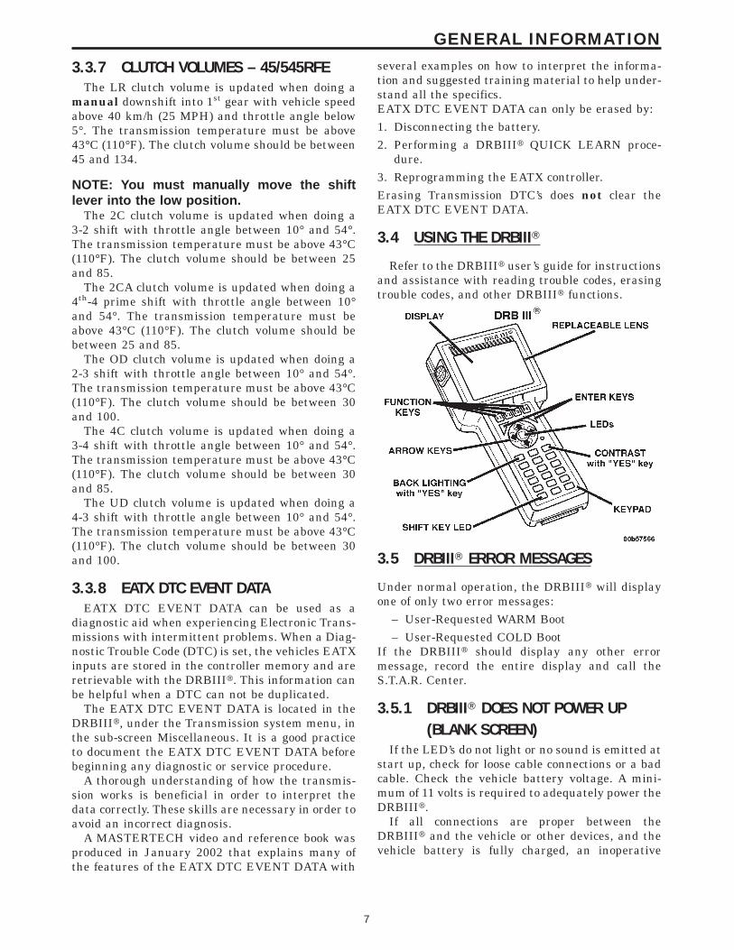
3.4 USING THE DRBIIIT
Refer to the DRBIIIt user’s guide for instructionsand assistance with reading trouble codes, erasingtrouble codes, and other DRBIIIt functions.
3.5 DRBIIIT ERROR MESSAGES
Under normal operation, the DRBIIIt will displayone of only two error messages:
– User-Requested WARM Boot– User-Requested COLD Boot
If the DRBIIIt should display any other errormessage, record the entire display and call theS.T.A.R. Center.
3.5.1 DRBIIIT DOES NOT POWER UP(BLANK SCREEN)
If the LED’s do not light or no sound is emitted atstart up, check for loose cable connections or a badcable. Check the vehicle battery voltage. A mini-mum of 11 volts is required to adequately power theDRBIIIt.
If all connections are proper between theDRBIIIt and the vehicle or other devices, and thevehicle battery is fully charged, an inoperative
7
GENERAL INFORMATION

DRBIIIt may be the result of faulty cable or vehiclewiring. For a blank screen, refer to the appropriateBody Diagnostic manual.
3.5.2 DISPLAY IS NOT VISIBLELow temperatures will affect the visibility of the
display. Adjust the contrast to compensate for thiscondition.
3.5.3 SOME DISPLAY ITEMS READ ‘‘---’’This is caused by the scrolling the DRBIIIt dis-
play a single line up or down. The line which wasscrolled onto the screen might read ‘‘---’’. Use thepage down or page up function to display theinformation.
3.6 TRANSMISSION SIMULATOR (MILLERTOOL #8333) AND ELECTRONICTRANSMISSION ADAPTER KIT(MILLER TOOL #8333-1A)
NOTE: Remove the starter Relay when usingthe transmission simulator.• Failure to remove the Starter Relay can
cause a PCM - No Response condition.• The removal of the Starter Relay will also
prevent the engine from starting in gear.• The Transmission Simulator will not
accurately diagnose intermittent faults.The transmission simulator, simply put, is
an electronic device that simulates the elec-tronic functions of any EATX or NGC con-trolled transmission. The Simulators basicfunction is to aid the technician in determin-ing if an internal transmission problem existsor if the problem resides in the vehicle wiringor control module. It is only useful for electri-cal problems. It will not aid in the diagnosis ofa failed mechanical component, but it can tellyou that the control module and wiring areworking properly and that the problem isinternal to the transmission.
The ignition switch should be in the lock positionbefore attempting to install the simulator. Followall instructions included with the simulator. If thefeedback from the simulator is in doubt, you canverify it’s operation by installing it on a known goodvehicle. A ‘‘known good vehicle’’ would be defined asa vehicle that does not set any DTC’s and drives andshifts as expected.
One important point to remember is that theSimulator receives it’s power from the Trans RelayOutput circuit. If the transmission system is inLimp-in (Relay open), the simulator will not oper-ate. Ths is not really an indication of a problem, butan additional symptom. If the simulator does not
power up (‘‘P’’ led lit), this is an indication that theproblem is still present with the simulator hookedup. This indicates that the problem is in the wiringor control module and not the transmission.
Miller Tool #8333-1A consists of the adapter ca-bles and overlay necessary to adapt the simulator toTE/AE/LE/RLE transmissions.
4.0 DISCLAIMERS, SAFETY,AND WARNINGS
4.1 DISCLAIMERS
All information, illustrations, and specificationscontained in this manual are based on the latestinformation available at the time of publication.The right is reserved to make changes at any timewithout notice.
4.2 SAFETY
4.2.1 TECHNICIAN SAFETY INFORMATION
WARNING: ENGINES PRODUCE CARBONMONOXIDE THAT IS ODORLESS, CAUSESSLOWER REACTION TIME, AND CAN LEADTO SERIOUS INJURY. WHEN THE ENGINE ISOPERATING KEEP SERVICE AREAS WELLVENTILATED OR ATTACH THE VEHICLEEXHAUST SYSTEM TO THE SHOP EXHAUSTREMOVAL SYSTEM.
Set the parking brake and block the wheels beforetesting or repairing the vehicle. It is especiallyimportant to block the wheels on front-wheel drivevehicles: the parking brake does not hold the drivewheels.
Some operations in this manual require thathydraulic tubes, hoses, and fittings, disconnectedfor inspection or testing purposes. These systems,when fully charged, contain fluid at high pressure.Before disconnecting any hydraulic tubes, hoses,and fittings, be sure that the system is fully depres-surized.
When servicing a vehicle, always wear eye pro-tection, and remove any metal jewelry such aswatchbands or bracelets that might make an inad-vertent electrical contact.
When diagnosing a Transmission system prob-lem, it is important to follow approved procedureswere applicable. These procedures can be found inthe service information. Following these proceduresis very important ot the safety of individuals per-forming diagnostic tests.
8
GENERAL INFORMATION

4.2.2 VEHICLE PREPARATION FORTESTING
Make sure the vehicle being tested has a fullycharged battery. If it does not, false diagnosticDTC’s or error messages may occur. It is extremelyimportant that accurate shift lever position data isavailable to the TCM. The accuracy of any DTCfound in memory is doutbful unless the Shift LeverTest, performed on the DRBIIIt Scan Tool, passeswithout failure.
4.2.3 SERVICING SUB-ASSEMBLIESSome components of the Transmission system are
intended to be serviced in assembly only. Attempt-ing to remove or repair certain system sub-components may result in personal injury and/orimproper system operation. Only those componentswith approved repair and installation procedures inthe service information should be serviced.
4.2.4 DRBIIIT SAFETY INFORMATION
WARNING: EXCEEDING THE LIMITS OF THEDRBIIIT MULTIMETER IS DANGEROUS. ITCAN EXPOSE YOU TO SERIOUS ORPOSSIBLY FATAL INJURY. CAREFULLYREAD AND UNDERSTAND THE CAUTIONSAND THE SPECIFICATION LIMITS.
• Follow the vehicle manufacturer’s service speci-fications at all times.
• Do not use the DRBIIIt if it has been damaged.• Do not use the test leads if the insulation is
damaged or if metal is exposed.• To avoid electrical shock, do not touch the test
leads, tips or the circuit being tested.• Choose the proper range and function for the
measurement. Do not try voltage or current mea-surements that may exceed the rated capacity.
• Do not exceed the limits shown in the table below:
FUNCTION INPUT LIMIT
Volts 0 - 500 volts peak AC0 - 500 volts DC
Ohms (resistance)* 0 -1.12 megohms
Frequency MeasuredFrequency Generated
0 - 10 khz
Temperature -58 - 1100°F-50 - 600°C
* Ohms cannot be measured if voltage is present.Ohms can be measured only in a non-poweredcircuit.
• Voltage between any terminal and ground mustnot exceed 500v DC or 500v peak AC.
• Use caution when measured voltage above 25vDC or 25v AC.
• The circuit being tested must be protected by a10A fuse or circuit breaker.
• Use the low current shunt to measure circuits upto 10A. Use the high current clamp to measurecircuits exceeding 10A.
• When testing for the presence of voltage or cur-rent, make sure the meter is functioning cor-rectly. Take a reading of a known voltage orcurrent before accepting a zero reading.
• When measuring current, connect the meter inseries with the load.
• Disconnect the live test lead before disconnectingthe common test lead.
• When using the meter function, keep theDRBIIIt away from spark plug or coil wires toavoid measuring error from outside interference.
4.3 WARNINGS
4.3.1 VEHICLE DAMAGE WARNINGSBefore disconnecting any control module, make
sure the ignition is ‘‘lock’’ position. Failure to do socould damage the module.
When testing voltage or continuity at any controlmodule, use the terminal side (not the wire end) ofthe connector. Do not probe a wire through theinsulation: this will damage the wire and eventu-ally cause the wire to fail because of corrosion.
Be careful when performing electrical tests so asto prevent accidental shorting of terminals. Suchmistakes can damage fuses or components. Also, asecond DTC could be set, making diagnosis of theoriginal problem more difficult.
When replacing a blown fuse, it is important touse only a fuse having the correct amperage rating.The use of a fuse with a rating other than indicatedmay result in a dangerous electrical system over-load. If a properly rated fuse continues to blow, itindicates a problem in the circuit that must becorrected.
4.3.2 ROAD TESTING A COMPLAINTVEHICLE
Some complaints will require a test drive as partof the repair verification procedure. The purpose ofthe test drive is to try to duplicate the diagnosticDTC or symptom condition.
9
GENERAL INFORMATION
CAUTION: Before road testing a vehicle, besure that all components are reassembled.During the test drive, do not try to readDRBIIIT screen while in motion. Do not hangthe DRBIII T from the rear view mirror oroperate it yourself. Have an assistantavailable to operate the DRBIII T.
Road testing is an essential step in the diagnosticprocess that must not be overlooked. Along with thediagnostic information obtained from the DRBIIItScan Tool and the original customer concern, theroad test helps verify the problem was current andany repairs performed, fixed the vehicle correctly.Always operate and observe the vehicle under ac-tual driving conditions.
Just as important as the road test is, there arepreliminary inspections that should be performedprior to the road test. Always check the fluid leveland condition before taking the vehicle on a roadtest. Determine if the incorrect fluid is being used,improper fluid will result in erratic transmissionoperation. Some of the conditions of incorrect fluidlevel are as follows:• Delayed engagement• Poor shifting or erratic shifting• Excessive noise• Overheating
The next step is to verify that the shifter iscorrectly adjusted. If the shifter is incorrectly ad-justed, a number of complaints can result.
The TCM monitors the Shift Lever Position (SLP)Sensor continuously. If the linkage is incorrectlyadjusted, the TCM will sense a shift lever positionthat is not correct for the gear chosen by the driver.This may cause a DTC to be set.
The following complaints may also be the resultof an incorrectly adjusted shifter:• Delayed clutch engagement• Erratic shifts• Vehicle will drive in neutral• Engine will not crank in park or neutral• Shifter will be able to be moved without the key
in the ignition• Not able to remove the ignition key in park• Parking pawl will not engage properly
The shift linkage should also be adjusted whenreplacing the Transmission, repairing the valvebody, or when repairing any component between theshift lever and the Transmission.
Some questions to ask yourself when performingthe road test are as follows:• Is the complaint or concern what you think the
problem is, based on the drivers description of theproblem?
• Is the Transmission operating normally, or isthere a real problem?
• When does the problem occur?• Is the problem only in one gear range• What temperature does the problem occur?• Does the vehicle have to sit over night for the
problem to occur?• Does the transmission go into Limp-in mode?
4.3.3 ELECTRONIC PINION FACTORWARNINGS (IF APPLICABLE)
The pinion factor must be set when replacing theTCM.
NOTE: The pinion factor is a fixed numberand cannot be changed or updated in somevehicle applications. If the pinion factor is notset or incorrectly set, any speed relatedfunctions will not operate correctly i.e.speedometer, speed control, rolling doorlocks, other control modules will be affectedthat depend on speed information.
4.4 BULLETINS AND RECALLS
Always perform all Safety Recalls and TechnicalService Bulletins that are applicable to the prob-lem.
5.0 REQUIRED TOOLS ANDEQUIPMENT
> DRBIIIt (diagnostic read-out box) – DRBIIItmust use the latest release level.
> Transmission Simulator (Miller #8333)> Line Pressure Adapter (Miller #8259)> Jumper wires> Test Light (minimum of 25 ohms of resistance)> Ohmmeter> Voltmeter> Pressure gauge 0-2068 kPa (0-300 PSI)
6.0 GLOSSARY OF TERMS
APPS accelerator pedal position sensor
BCM body control module
CKT circuit
CVI clutch volume index
DLC data link connector
10
GENERAL INFORMATION

DRBIIIt diagnostic readout box
DTC diagnostic trouble code
EATX electronic automatic transmission
EMCC electronically modulated converterclutch
FCM front control module (part of theIPM system)
FEMCC full electronically modulated con-verter clutch
IOD ignition off-draw
IRT intelligent recovery timer
ISS input speed sensor
LED light emitting diode
LPS line pressure sensor
LR low/reverse clutch
MIC mechanical instrument cluster
MIL malfunction indicator lamp
MS multi select
OBDII on board diagnostics
OD overdrive clutch
OSS output speed sensor
PCI programmable controller interface(vehicle bus system)
PCM powertrain control module
PCS pressure control solenoid
PEMCC partial electronically modulatedconverter clutch
REV reverse clutch
SSV solenoid switch valve
SW switch
TCC torque converter clutch
TCM transmission control module
TCCM transfer case control module
TP throttle position
TRD torque reduction
TRS transmission range sensor
TTS transmission temperature sensor
UD underdrive clutch
2C 2nd clutch
4C 4th clutch
2/4 2nd and 4th gear clutch or pressureswitch
6.2 DEFINITIONS
OBDII/EURO III Trip – A vehicle start and drivecycle such that all once per trip diagnostic monitorshave run.Key Start – A vehicle start and run cycle of at least20 seconds.Warm-up Cycle – A vehicle start and run cycle suchthat the engine coolant must rise to at least 71 C(160°F) and must rise by at least 22 C (40°F) frominitial start up. To count as a warm-up cycle, noDTC’s may occur during the cycle.
11
GENERAL INFORMATION

NOTES
12
7.0
DIAGNOSTIC INFORMATION ANDPROCEDURES
13
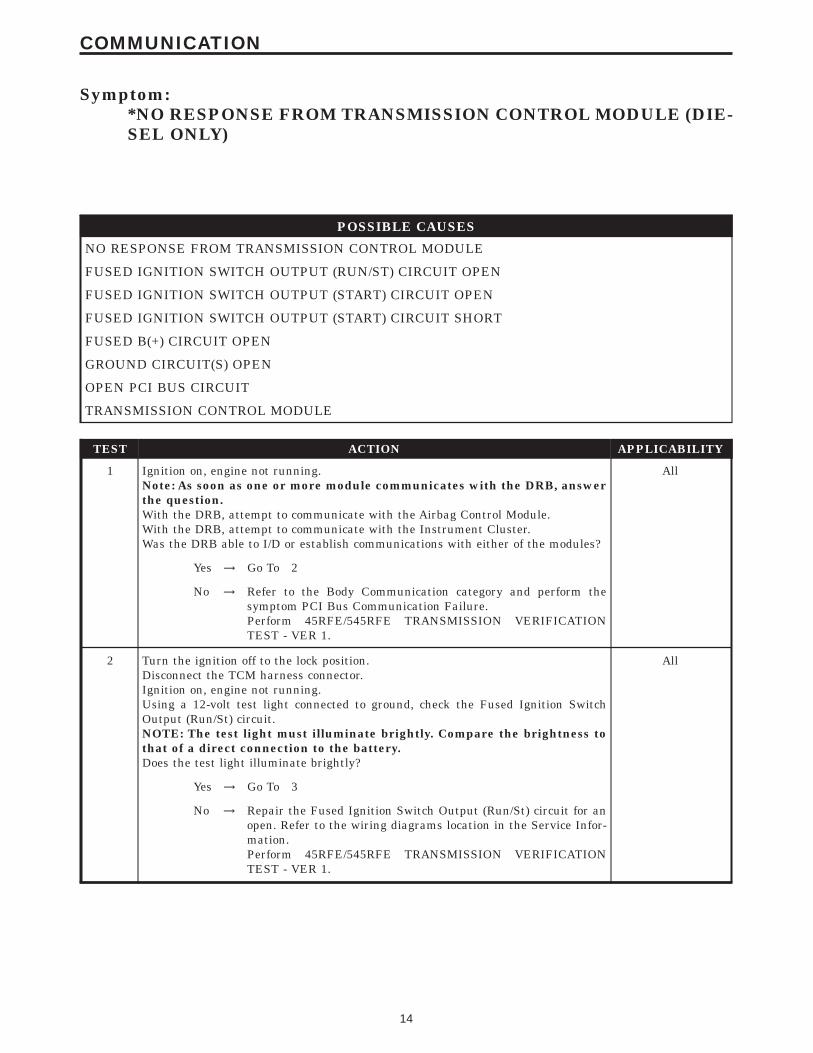
Symptom:*NO RESPONSE FROM TRANSMISSION CONTROL MODULE (DIE-SEL ONLY)
POSSIBLE CAUSES
NO RESPONSE FROM TRANSMISSION CONTROL MODULE
FUSED IGNITION SWITCH OUTPUT (RUN/ST) CIRCUIT OPEN
FUSED IGNITION SWITCH OUTPUT (START) CIRCUIT OPEN
FUSED IGNITION SWITCH OUTPUT (START) CIRCUIT SHORT
FUSED B(+) CIRCUIT OPEN
GROUND CIRCUIT(S) OPEN
OPEN PCI BUS CIRCUIT
TRANSMISSION CONTROL MODULE
TEST ACTION APPLICABILITY
1 Ignition on, engine not running.Note: As soon as one or more module communicates with the DRB, answerthe question.With the DRB, attempt to communicate with the Airbag Control Module.With the DRB, attempt to communicate with the Instrument Cluster.Was the DRB able to I/D or establish communications with either of the modules?
All
Yes → Go To 2
No → Refer to the Body Communication category and perform thesymptom PCI Bus Communication Failure.Perform 45RFE/545RFE TRANSMISSION VERIFICATIONTEST - VER 1.
2 Turn the ignition off to the lock position.Disconnect the TCM harness connector.Ignition on, engine not running.Using a 12-volt test light connected to ground, check the Fused Ignition SwitchOutput (Run/St) circuit.NOTE: The test light must illuminate brightly. Compare the brightness tothat of a direct connection to the battery.Does the test light illuminate brightly?
All
Yes → Go To 3
No → Repair the Fused Ignition Switch Output (Run/St) circuit for anopen. Refer to the wiring diagrams location in the Service Infor-mation.Perform 45RFE/545RFE TRANSMISSION VERIFICATIONTEST - VER 1.
14
COMMUNICATION
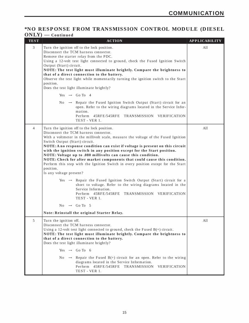
TEST ACTION APPLICABILITY
3 Turn the ignition off to the lock position.Disconnect the TCM harness connector.Remove the starter relay from the PDC.Using a 12-volt test light connected to ground, check the Fused Ignition SwitchOutput (Start) circuit.NOTE: The test light must illuminate brightly. Compare the brightness tothat of a direct connection to the battery.Observe the test light while momentarily turning the ignition switch to the Startposition.Does the test light illuminate brightly?
All
Yes → Go To 4
No → Repair the Fused Ignition Switch Output (Start) circuit for anopen. Refer to the wiring diagrams located in the Service Infor-mation.Perform 45RFE/545RFE TRANSMISSION VERIFICATIONTEST - VER 1.
4 Turn the ignition off to the lock position.Disconnect the TCM harness connector.With a voltmeter in the millivolt scale, measure the voltage of the Fused IgnitionSwitch Output (Start) circuit.NOTE: A no response condition can exist if voltage is present on this circuitwith the ignition switch in any position except for the Start position.NOTE: Voltage up to .080 millivolts can cause this condition.NOTE: Check for after market components that could cause this condition.Perform this step with the Ignition Switch in every position except for the Startposition.Is any voltage present?
All
Yes → Repair the Fused Ignition Switch Output (Start) circuit for ashort to voltage. Refer to the wiring diagrams located in theService Information.Perform 45RFE/545RFE TRANSMISSION VERIFICATIONTEST - VER 1.
No → Go To 5
Note: Reinstall the original Starter Relay.
5 Turn the ignition off.Disconnect the TCM harness connector.Using a 12-volt test light connected to ground, check the Fused B(+) circuit.NOTE: The test light must illuminate brightly. Compare the brightness tothat of a direct connection to the battery.Does the test light illuminate brightly?
All
Yes → Go To 6
No → Repair the Fused B(+) circuit for an open. Refer to the wiringdiagrams located in the Service Information.Perform 45RFE/545RFE TRANSMISSION VERIFICATIONTEST - VER 1.
15
COMMUNICATION
*NO RESPONSE FROM TRANSMISSION CONTROL MODULE (DIESELONLY) — Continued

TEST ACTION APPLICABILITY
6 Turn the ignition off to the lock position.Disconnect the TCM harness connector.Using a 12-volt test light connected to 12-volts, check each ground circuit in the TCMharness connector.NOTE: The test light must illuminate brightly. Compare the brightness tothat of a direct connection to the battery.Does the test light illuminate brightly at all the ground circuits?
All
Yes → Go To 7
No → Repair the Ground circuit(s) for an open. Check the main groundconnection to engine block and/or chassis. Refer to the wiringdiagrams located in the Service Information.Perform 45RFE/545RFE TRANSMISSION VERIFICATIONTEST - VER 1.
7 Note: Ensure there is PCI Bus communication with other modules on thevehicle before proceeding. If not, refer to the symptom list from the menuand repair as necessary.Disconnect the TCM harness connector.Use Scope input cable CH7058, Cable to Probe adapter CH7062, and the red andblack test probes.Connect the scope input cable to the channel one connector on the DRB. Attach thered and black leads and the cable to probe adapter to the scope input cable.With the DRBIIIt select Pep Module Tools.Select lab scope.Select Live Data.Select 12 volt square wave.Press F2 for Scope.Press F2 and use the down arrow to set voltage range to 20 volts. Press F2 againwhen complete.Connect the Black lead to the chassis ground. Connect the Red lead to the PCI Buscircuit in the TCM connector.Turn the ignition on.Observe the voltage display on the DRB Lab Scope.Does the voltage pulse from 0 to approximately 7.5 volts?
All
Yes → Replace the Transmission Control Module in accordance with theservice information.Perform 45RFE/545RFE TRANSMISSION VERIFICATIONTEST - VER 1.
No → Repair the PCI Bus circuit for an open.Perform 45RFE/545RFE TRANSMISSION VERIFICATIONTEST - VER 1.
16
COMMUNICATION
*NO RESPONSE FROM TRANSMISSION CONTROL MODULE (DIESELONLY) — Continued
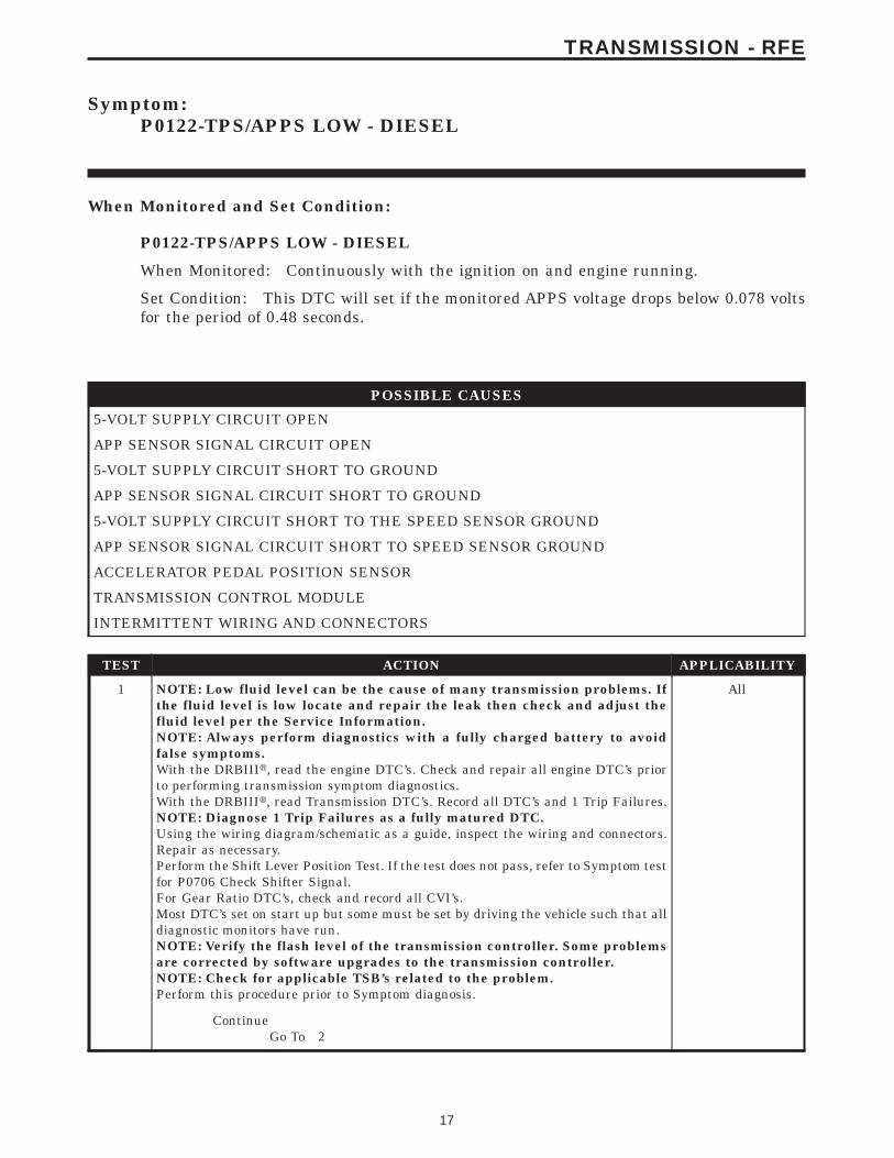
Symptom:P0122-TPS/APPS LOW - DIESEL
When Monitored and Set Condition:
P0122-TPS/APPS LOW - DIESEL
When Monitored: Continuously with the ignition on and engine running.
Set Condition: This DTC will set if the monitored APPS voltage drops below 0.078 voltsfor the period of 0.48 seconds.
POSSIBLE CAUSES
5-VOLT SUPPLY CIRCUIT OPEN
APP SENSOR SIGNAL CIRCUIT OPEN
5-VOLT SUPPLY CIRCUIT SHORT TO GROUND
APP SENSOR SIGNAL CIRCUIT SHORT TO GROUND
5-VOLT SUPPLY CIRCUIT SHORT TO THE SPEED SENSOR GROUND
APP SENSOR SIGNAL CIRCUIT SHORT TO SPEED SENSOR GROUND
ACCELERATOR PEDAL POSITION SENSOR
TRANSMISSION CONTROL MODULE
INTERMITTENT WIRING AND CONNECTORS
TEST ACTION APPLICABILITY
1 NOTE: Low fluid level can be the cause of many transmission problems. Ifthe fluid level is low locate and repair the leak then check and adjust thefluid level per the Service Information.NOTE: Always perform diagnostics with a fully charged battery to avoidfalse symptoms.With the DRBIIIt, read the engine DTC’s. Check and repair all engine DTC’s priorto performing transmission symptom diagnostics.With the DRBIIIt, read Transmission DTC’s. Record all DTC’s and 1 Trip Failures.NOTE: Diagnose 1 Trip Failures as a fully matured DTC.Using the wiring diagram/schematic as a guide, inspect the wiring and connectors.Repair as necessary.Perform the Shift Lever Position Test. If the test does not pass, refer to Symptom testfor P0706 Check Shifter Signal.For Gear Ratio DTC’s, check and record all CVI’s.Most DTC’s set on start up but some must be set by driving the vehicle such that alldiagnostic monitors have run.NOTE: Verify the flash level of the transmission controller. Some problemsare corrected by software upgrades to the transmission controller.NOTE: Check for applicable TSB’s related to the problem.Perform this procedure prior to Symptom diagnosis.
All
ContinueGo To 2
17
TRANSMISSION - RFE
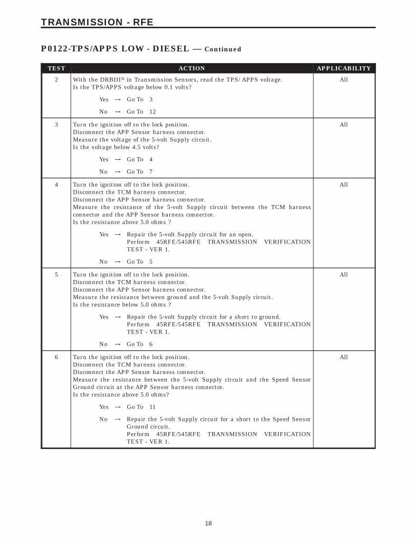
TEST ACTION APPLICABILITY
2 With the DRBIIIt in Transmission Sensors, read the TPS/ APPS voltage.Is the TPS/APPS voltage below 0.1 volts?
All
Yes → Go To 3
No → Go To 12
3 Turn the ignition off to the lock position.Disconnect the APP Sensor harness connector.Measure the voltage of the 5-volt Supply circuit.Is the voltage below 4.5 volts?
All
Yes → Go To 4
No → Go To 7
4 Turn the ignition off to the lock position.Disconnect the TCM harness connector.Disconnect the APP Sensor harness connector.Measure the resistance of the 5-volt Supply circuit between the TCM harnessconnector and the APP Sensor harness connector.Is the resistance above 5.0 ohms ?
All
Yes → Repair the 5-volt Supply circuit for an open.Perform 45RFE/545RFE TRANSMISSION VERIFICATIONTEST - VER 1.
No → Go To 5
5 Turn the ignition off to the lock position.Disconnect the TCM harness connector.Disconnect the APP Sensor harness connector.Measure the resistance between ground and the 5-volt Supply circuit.Is the resistance below 5.0 ohms ?
All
Yes → Repair the 5-volt Supply circuit for a short to ground.Perform 45RFE/545RFE TRANSMISSION VERIFICATIONTEST - VER 1.
No → Go To 6
6 Turn the ignition off to the lock position.Disconnect the TCM harness connector.Disconnect the APP Sensor harness connector.Measure the resistance between the 5-volt Supply circuit and the Speed SensorGround circuit at the APP Sensor harness connector.Is the resistance above 5.0 ohms?
All
Yes → Go To 11
No → Repair the 5-volt Supply circuit for a short to the Speed SensorGround circuit.Perform 45RFE/545RFE TRANSMISSION VERIFICATIONTEST - VER 1.
18
TRANSMISSION - RFE
P0122-TPS/APPS LOW - DIESEL — Continued
TEST ACTION APPLICABILITY
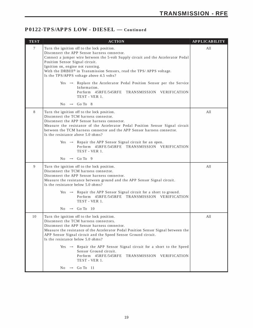
7 Turn the ignition off to the lock position.Disconnect the APP Sensor harness connector.Connect a jumper wire between the 5-volt Supply circuit and the Accelerator PedalPosition Sensor Signal circuit.Ignition on, engine not running.With the DRBIIIt in Transmission Sensors, read the TPS/ APPS voltage.Is the TPS/APPS voltage above 4.5 volts?
All
Yes → Replace the Accelerator Pedal Position Sensor per the ServiceInformation.Perform 45RFE/545RFE TRANSMISSION VERIFICATIONTEST - VER 1.
No → Go To 8
8 Turn the ignition off to the lock position.Disconnect the TCM harness connector.Disconnect the APP Sensor harness connector.Measure the resistance of the Accelerator Pedal Position Sensor Signal circuitbetween the TCM harness connector and the APP Sensor harness connector.Is the resistance above 5.0 ohms?
All
Yes → Repair the APP Sensor Signal circuit for an open.Perform 45RFE/545RFE TRANSMISSION VERIFICATIONTEST - VER 1.
No → Go To 9
9 Turn the ignition off to the lock position.Disconnect the TCM harness connector.Disconnect the APP Sensor harness connector.Measure the resistance between ground and the APP Sensor Signal circuit.Is the resistance below 5.0 ohms?
All
Yes → Repair the APP Sensor Signal circuit for a short to ground.Perform 45RFE/545RFE TRANSMISSION VERIFICATIONTEST - VER 1.
No → Go To 10
10 Turn the ignition off to the lock position.Disconnect the TCM harness connectors.Disconnect the APP Sensor harness connector.Measure the resistance of the Accelerator Pedal Position Sensor Signal between theAPP Sensor Signal circuit and the Speed Sensor Ground circuit.Is the resistance below 5.0 ohms?
All
Yes → Repair the APP Sensor Signal circuit for a short to the SpeedSensor Ground circuit.Perform 45RFE/545RFE TRANSMISSION VERIFICATIONTEST - VER 1.
No → Go To 11
19
TRANSMISSION - RFE
P0122-TPS/APPS LOW - DIESEL — Continued

TEST ACTION APPLICABILITY
11 Using the schematics as a guide, inspect the wiring and connectors. Repair asnecessary. Pay particular attention to all power and ground circuits.If there are no possible causes remaining, view repair.
All
RepairReplace the Transmission Control Module per the Service Infor-mation. WITH THE DRBIIIt PERFORM QUICK LEARN.Perform 45RFE/545RFE TRANSMISSION VERIFICATIONTEST - VER 1.
12 The conditions necessary to set this DTC are not present at this time.Using the schematics as a guide, inspect the wiring and connectors specific to thiscircuit.Wiggle the wires while checking for shorts and open circuits.With the DRBIIIt, check the EATX EVENT DATA to help identify the conditions inwhich the DTC was set.Were there any problems found?
All
Yes → Repair as necessary.Perform 45RFE/545RFE TRANSMISSION VERIFICATIONTEST - VER 1.
No → Test Complete.
20
TRANSMISSION - RFE
P0122-TPS/APPS LOW - DIESEL — Continued

Symptom:P0123-TPS/APPS HIGH - DIESEL
When Monitored and Set Condition:
P0123-TPS/APPS HIGH - DIESEL
When Monitored: Continuously with the ignition on and engine running.
Set Condition: This DTC will set if the monitored APPS voltage rises above 4.94 volts forthe period of 0.48 seconds.
POSSIBLE CAUSES
SPEED SENSOR GROUND CIRCUIT OPEN
5-VOLT SUPPLY CIRCUIT SHORT TO VOLTAGE
APP SENSOR SIGNAL CIRCUIT SHORT TO VOLTAGE
SPEED SENSOR GROUND CIRCUIT SHORT TO VOLTAGE
ACCELERATOR PEDAL POSITION SENSOR
TRANSMISSION CONTROL MODULE
INTERMITTENT WIRING AND CONNECTORS
TEST ACTION APPLICABILITY
1 NOTE: Low fluid level can be the cause of many transmission problems. Ifthe fluid level is low locate and repair the leak then check and adjust thefluid level per the Service Information.NOTE: Always perform diagnostics with a fully charged battery to avoidfalse symptoms.With the DRBIIIt, read the engine DTC’s. Check and repair all engine DTC’s priorto performing transmission symptom diagnostics.With the DRBIIIt, read Transmission DTC’s. Record all DTC’s and 1 Trip Failures.NOTE: Diagnose 1 Trip Failures as a fully matured DTC.Using the wiring diagram/schematic as a guide, inspect the wiring and connectors.Repair as necessary.Perform the Shift Lever Position Test. If the test does not pass, refer to Symptom testfor P0706 Check Shifter Signal.For Gear Ratio DTC’s, check and record all CVI’s.Most DTC’s set on start up but some must be set by driving the vehicle such that alldiagnostic monitors have run.NOTE: Verify the flash level of the transmission controller. Some problemsare corrected by software upgrades to the transmission controller.NOTE: Check for applicable TSB’s related to the problem.Perform this procedure prior to Symptom diagnosis.
All
ContinueGo To 2
21
TRANSMISSION - RFE

TEST ACTION APPLICABILITY
2 Ignition on, engine not running.Press the accelerator pedal all the way down to wide open throttle.With the DRBIIIt in Transmission Sensors, read the TPS/APPS voltage.Is the TPS/APPS voltage above 4.94 volts?
All
Yes → Go To 3
No → Go To 11
3 Turn the ignition off to the lock position.Disconnect the APP Sensor harness connector.Ignition on, engine not running.With the DRBIIIt in Transmission Sensors, read the TPS/APPS voltage.Is the voltage above 0.5 volts?
All
Yes → Go To 4
No → Go To 5
4 Turn the ignition off to the lock position.Disconnect the APP Sensor harness connector.Disconnect the TCM harness connector.Remove the Transmission Control Relay.Connect a jumper wire between the Fused B+ circuit and the Transmission ControlRelay Output circuit in the Transmission Control Relay connector.Ignition on, engine not running.Measure the voltage of the APP Sensor Signal circuit.Is the voltage above 0.5 volt?
All
Yes → Repair the APP Sensor Signal circuit for a short to voltage.Perform 45RFE/545RFE TRANSMISSION VERIFICATIONTEST - VER 1.
No → Go To 10
5 Turn the ignition off to the lock position.Disconnect the APP Sensor harness connector.Ignition on, engine not running.Measure the voltage of the 5-volt Supply circuit.Is the voltage above 5.5 volts?
All
Yes → Go To 6
No → Go To 7
6 Turn the ignition off to the lock position.Disconnect the APP Sensor harness connector.Disconnect the TCM harness connector.Remove the Transmission Control Relay.Connect a jumper wire between the Fused B+ circuit and the Transmission ControlRelay Output circuit in the Transmission Control Relay connector.Ignition on, engine not running.Measure the voltage of the 5-volt Supply circuit.Is the voltage above 0.5 volt?
All
Yes → Repair the 5-volt Supply circuit for a short to voltage.Perform 45RFE/545RFE TRANSMISSION VERIFICATIONTEST - VER 1.
No → Go To 10
22
TRANSMISSION - RFE
P0123-TPS/APPS HIGH - DIESEL — Continued
TEST ACTION APPLICABILITY
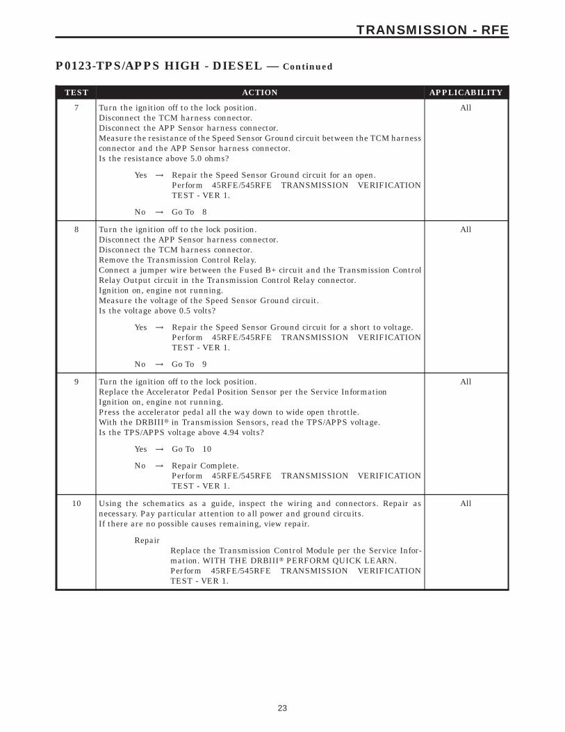
7 Turn the ignition off to the lock position.Disconnect the TCM harness connector.Disconnect the APP Sensor harness connector.Measure the resistance of the Speed Sensor Ground circuit between the TCM harnessconnector and the APP Sensor harness connector.Is the resistance above 5.0 ohms?
All
Yes → Repair the Speed Sensor Ground circuit for an open.Perform 45RFE/545RFE TRANSMISSION VERIFICATIONTEST - VER 1.
No → Go To 8
8 Turn the ignition off to the lock position.Disconnect the APP Sensor harness connector.Disconnect the TCM harness connector.Remove the Transmission Control Relay.Connect a jumper wire between the Fused B+ circuit and the Transmission ControlRelay Output circuit in the Transmission Control Relay connector.Ignition on, engine not running.Measure the voltage of the Speed Sensor Ground circuit.Is the voltage above 0.5 volts?
All
Yes → Repair the Speed Sensor Ground circuit for a short to voltage.Perform 45RFE/545RFE TRANSMISSION VERIFICATIONTEST - VER 1.
No → Go To 9
9 Turn the ignition off to the lock position.Replace the Accelerator Pedal Position Sensor per the Service InformationIgnition on, engine not running.Press the accelerator pedal all the way down to wide open throttle.With the DRBIIIt in Transmission Sensors, read the TPS/APPS voltage.Is the TPS/APPS voltage above 4.94 volts?
All
Yes → Go To 10
No → Repair Complete.Perform 45RFE/545RFE TRANSMISSION VERIFICATIONTEST - VER 1.
10 Using the schematics as a guide, inspect the wiring and connectors. Repair asnecessary. Pay particular attention to all power and ground circuits.If there are no possible causes remaining, view repair.
All
RepairReplace the Transmission Control Module per the Service Infor-mation. WITH THE DRBIIIt PERFORM QUICK LEARN.Perform 45RFE/545RFE TRANSMISSION VERIFICATIONTEST - VER 1.
23
TRANSMISSION - RFE
P0123-TPS/APPS HIGH - DIESEL — Continued

TEST ACTION APPLICABILITY
11 The conditions necessary to set this DTC are not present at this time.Using the schematics as a guide, inspect the wiring and connectors specific to thiscircuit.Wiggle the wires while checking for shorts and open circuits.With the DRBIIIt, check the EATX EVENT DATA to help identify the conditions inwhich the DTC was set.Were there any problems found?
All
Yes → Repair as necessary.Perform 45RFE/545RFE TRANSMISSION VERIFICATIONTEST - VER 1.
No → Test Complete.
24
TRANSMISSION - RFE
P0123-TPS/APPS HIGH - DIESEL — Continued

Symptom:P0124-TPS/APPS INTERMITTENT - DIESEL
When Monitored and Set Condition:
P0124-TPS/APPS INTERMITTENT - DIESEL
When Monitored: Continuously with the ignition on and engine running.
Set Condition: This DTC will set with a throttle angle between 6° and 120.6° with a 5° orhigher change under 7.0 milliseconds.
POSSIBLE CAUSES
RELATED DTCS PRESENT
WIRING AND CONNECTORS
ACCELERATOR PEDAL POSITION SENSOR
TRANSMISSION CONTROL MODULE
TEST ACTION APPLICABILITY
1 NOTE: Low fluid level can be the cause of many transmission problems. Ifthe fluid level is low locate and repair the leak then check and adjust thefluid level per the Service Information.NOTE: Always perform diagnostics with a fully charged battery to avoidfalse symptoms.With the DRBIIIt, read the engine DTC’s. Check and repair all engine DTC’s priorto performing transmission symptom diagnostics.With the DRBIIIt, read Transmission DTC’s. Record all DTC’s and 1 Trip Failures.NOTE: Diagnose 1 Trip Failures as a fully matured DTC.Using the wiring diagram/schematic as a guide, inspect the wiring and connectors.Repair as necessary.Perform the Shift Lever Position Test. If the test does not pass, refer to Symptom testfor P0706 Check Shifter Signal.For Gear Ratio DTC’s, check and record all CVI’s.Most DTC’s set on start up but some must be set by driving the vehicle such that alldiagnostic monitors have run.NOTE: Verify the flash level of the transmission controller. Some problemsare corrected by software upgrades to the transmission controller.NOTE: Check for applicable TSB’s related to the problem.Perform this procedure prior to Symptom diagnosis.
All
ContinueGo To 2
2 With the DRBIIIt, read Transmission DTCs.Are there any APPS/TPS High or Low DTCs present?
All
Yes → Refer to the Transmission category and perform the appropriatesymptom.Perform 45RFE/545RFE TRANSMISSION VERIFICATIONTEST - VER 1.
No → Go To 3
25
TRANSMISSION - RFE
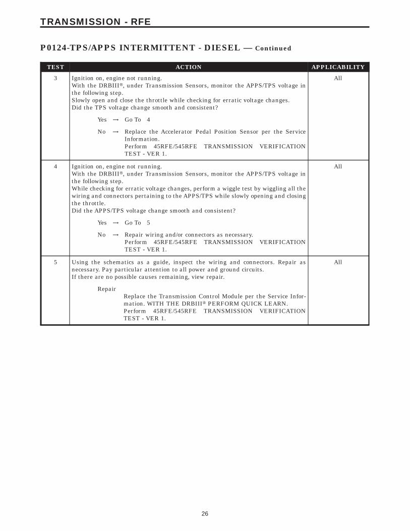
TEST ACTION APPLICABILITY
3 Ignition on, engine not running.With the DRBIIIt, under Transmission Sensors, monitor the APPS/TPS voltage inthe following step.Slowly open and close the throttle while checking for erratic voltage changes.Did the TPS voltage change smooth and consistent?
All
Yes → Go To 4
No → Replace the Accelerator Pedal Position Sensor per the ServiceInformation.Perform 45RFE/545RFE TRANSMISSION VERIFICATIONTEST - VER 1.
4 Ignition on, engine not running.With the DRBIIIt, under Transmission Sensors, monitor the APPS/TPS voltage inthe following step.While checking for erratic voltage changes, perform a wiggle test by wiggling all thewiring and connectors pertaining to the APPS/TPS while slowly opening and closingthe throttle.Did the APPS/TPS voltage change smooth and consistent?
All
Yes → Go To 5
No → Repair wiring and/or connectors as necessary.Perform 45RFE/545RFE TRANSMISSION VERIFICATIONTEST - VER 1.
5 Using the schematics as a guide, inspect the wiring and connectors. Repair asnecessary. Pay particular attention to all power and ground circuits.If there are no possible causes remaining, view repair.
All
RepairReplace the Transmission Control Module per the Service Infor-mation. WITH THE DRBIIIt PERFORM QUICK LEARN.Perform 45RFE/545RFE TRANSMISSION VERIFICATIONTEST - VER 1.
26
TRANSMISSION - RFE
P0124-TPS/APPS INTERMITTENT - DIESEL — Continued

Symptom:P0218-HIGH TEMPERATURE OPERATION ACTIVATED
When Monitored and Set Condition:
P0218-HIGH TEMPERATURE OPERATION ACTIVATED
When Monitored: Whenever the engine is running.
Set Condition: This DTC is an informational code and does not necessarily indicate thata failure exists. It merely flags the fact that trans sump oil temperature reached 116° C or240F. This temperature level can be reached when operating under heavy load in hotweather. This causes the transmission controller to use an 9overheat9 shift schedule, whichchanges the shift patterns in an attempt to control the temperature. Customers may noticea different feeling or response under these conditions. The Owner’s Manual includes anexplanation of this 9Over Temperature Mode9 for the customer’s information. The DTC setsimmediately when the Overheat shift schedule is activated with a Transmission OilTemperature above 116° C or 240° F.
POSSIBLE CAUSES
SEVERE OPERATION TRAILER TOW IN HOT WEATHER
ENGINE COOLING SYSTEM
OIL PUMP VOLUME CHECK
TORQUE CONVERTOR FAILURE
HIGH TEMPERATURE OPERATIONS ACTIVATED
TEST ACTION APPLICABILITY
1 NOTE: Low fluid level can be the cause of many transmission problems. Ifthe fluid level is low locate and repair the leak then check and adjust thefluid level per the Service Information.NOTE: Always perform diagnostics with a fully charged battery to avoidfalse symptoms.With the DRBIIIt, read the engine DTC’s. Check and repair all engine DTC’s priorto performing transmission symptom diagnostics.With the DRBIIIt, read Transmission DTC’s. Record all DTC’s and 1 Trip Failures.NOTE: Diagnose 1 Trip Failures as a fully matured DTC.Using the wiring diagram/schematic as a guide, inspect the wiring and connectors.Repair as necessary.Perform the Shift Lever Position Test. If the test does not pass, refer to Symptom testfor P0706 Check Shifter Signal.For Gear Ratio DTC’s, check and record all CVI’s.Most DTC’s set on start up but some must be set by driving the vehicle such that alldiagnostic monitors have run.NOTE: Verify the flash level of the transmission controller. Some problemsare corrected by software upgrades to the transmission controller.NOTE: Check for applicable TSB’s related to the problem.Perform this procedure prior to Symptom diagnosis.
All
ContinueGo To 2
27
TRANSMISSION - RFE
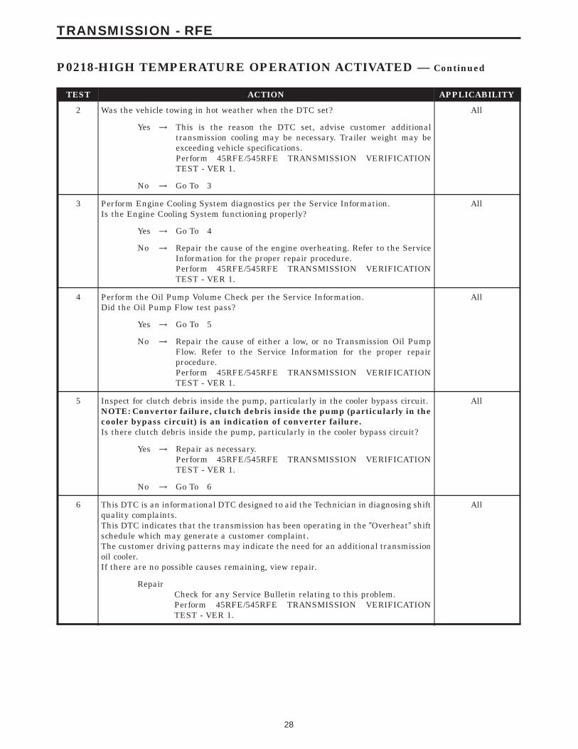
TEST ACTION APPLICABILITY
2 Was the vehicle towing in hot weather when the DTC set? All
Yes → This is the reason the DTC set, advise customer additionaltransmission cooling may be necessary. Trailer weight may beexceeding vehicle specifications.Perform 45RFE/545RFE TRANSMISSION VERIFICATIONTEST - VER 1.
No → Go To 3
3 Perform Engine Cooling System diagnostics per the Service Information.Is the Engine Cooling System functioning properly?
All
Yes → Go To 4
No → Repair the cause of the engine overheating. Refer to the ServiceInformation for the proper repair procedure.Perform 45RFE/545RFE TRANSMISSION VERIFICATIONTEST - VER 1.
4 Perform the Oil Pump Volume Check per the Service Information.Did the Oil Pump Flow test pass?
All
Yes → Go To 5
No → Repair the cause of either a low, or no Transmission Oil PumpFlow. Refer to the Service Information for the proper repairprocedure.Perform 45RFE/545RFE TRANSMISSION VERIFICATIONTEST - VER 1.
5 Inspect for clutch debris inside the pump, particularly in the cooler bypass circuit.NOTE: Convertor failure, clutch debris inside the pump (particularly in thecooler bypass circuit) is an indication of converter failure.Is there clutch debris inside the pump, particularly in the cooler bypass circuit?
All
Yes → Repair as necessary.Perform 45RFE/545RFE TRANSMISSION VERIFICATIONTEST - VER 1.
No → Go To 6
6 This DTC is an informational DTC designed to aid the Technician in diagnosing shiftquality complaints.This DTC indicates that the transmission has been operating in the 9Overheat9 shiftschedule which may generate a customer complaint.The customer driving patterns may indicate the need for an additional transmissionoil cooler.If there are no possible causes remaining, view repair.
All
RepairCheck for any Service Bulletin relating to this problem.Perform 45RFE/545RFE TRANSMISSION VERIFICATIONTEST - VER 1.
28
TRANSMISSION - RFE
P0218-HIGH TEMPERATURE OPERATION ACTIVATED — Continued
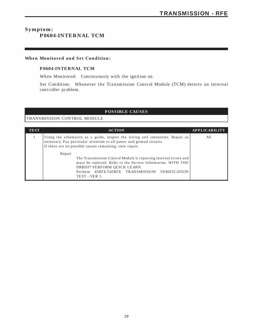
Symptom:P0604-INTERNAL TCM
When Monitored and Set Condition:
P0604-INTERNAL TCM
When Monitored: Continuously with the ignition on.
Set Condition: Whenever the Transmission Control Module (TCM) detects an internalcontroller problem.
POSSIBLE CAUSES
TRANSMISSION CONTROL MODULE
TEST ACTION APPLICABILITY
1 Using the schematics as a guide, inspect the wiring and connectors. Repair asnecessary. Pay particular attention to all power and ground circuits.If there are no possible causes remaining, view repair.
All
RepairThe Transmission Control Module is reporting internal errors andmust be replaced. Refer to the Service Information. WITH THEDRBIIIt PERFORM QUICK LEARN.Perform 45RFE/545RFE TRANSMISSION VERIFICATIONTEST - VER 1.
29
TRANSMISSION - RFE

Symptom:P0605-INTERNAL TCM
When Monitored and Set Condition:
P0605-INTERNAL TCM
When Monitored: Continuously with the ignition on
Set Condition: Whenever the Transmission Control Module (TCM) detects an internalcontroller problem.
POSSIBLE CAUSES
TRANSMISSION CONTROL MODULE
TEST ACTION APPLICABILITY
1 Using the schematics as a guide, inspect the wiring and connectors. Repair asnecessary. Pay particular attention to all power and ground circuits.If there are no possible causes remaining, view repair.
All
RepairThe Transmission Control Module is reporting internal errors andmust be replaced. WITH THE DRBIIIt PERFORM QUICKLEARN.Perform 45RFE/545RFE TRANSMISSION VERIFICATIONTEST - VER 1.
30
TRANSMISSION - RFE
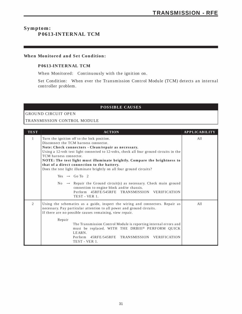
Symptom:P0613-INTERNAL TCM
When Monitored and Set Condition:
P0613-INTERNAL TCM
When Monitored: Continuously with the ignition on.
Set Condition: When ever the Transmission Control Module (TCM) detects an internalcontroller problem.
POSSIBLE CAUSES
GROUND CIRCUIT OPEN
TRANSMISSION CONTROL MODULE
TEST ACTION APPLICABILITY
1 Turn the ignition off to the lock position.Disconnect the TCM harness connector.Note: Check connectors - Clean/repair as necessary.Using a 12-volt test light connected to 12-volts, check all four ground circuits in theTCM harness connector.NOTE: The test light must illuminate brightly. Compare the brightness tothat of a direct connection to the battery.Does the test light illuminate brightly on all four ground circuits?
All
Yes → Go To 2
No → Repair the Ground circuit(s) as necessary. Check main groundconnection to engine block and/or chassis.Perform 45RFE/545RFE TRANSMISSION VERIFICATIONTEST - VER 1.
2 Using the schematics as a guide, inspect the wiring and connectors. Repair asnecessary. Pay particular attention to all power and ground circuits.If there are no possible causes remaining, view repair.
All
RepairThe Transmission Control Module is reporting internal errors andmust be replaced. WITH THE DRBIIIt PERFORM QUICKLEARN.Perform 45RFE/545RFE TRANSMISSION VERIFICATIONTEST - VER 1.
31
TRANSMISSION - RFE
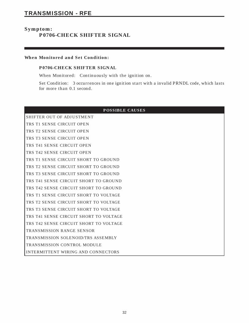
Symptom:P0706-CHECK SHIFTER SIGNAL
When Monitored and Set Condition:
P0706-CHECK SHIFTER SIGNAL
When Monitored: Continuously with the ignition on.
Set Condition: 3 occurrences in one ignition start with a invalid PRNDL code, which lastsfor more than 0.1 second.
POSSIBLE CAUSES
SHIFTER OUT OF ADJUSTMENT
TRS T1 SENSE CIRCUIT OPEN
TRS T2 SENSE CIRCUIT OPEN
TRS T3 SENSE CIRCUIT OPEN
TRS T41 SENSE CIRCUIT OPEN
TRS T42 SENSE CIRCUIT OPEN
TRS T1 SENSE CIRCUIT SHORT TO GROUND
TRS T2 SENSE CIRCUIT SHORT TO GROUND
TRS T3 SENSE CIRCUIT SHORT TO GROUND
TRS T41 SENSE CIRCUIT SHORT TO GROUND
TRS T42 SENSE CIRCUIT SHORT TO GROUND
TRS T1 SENSE CIRCUIT SHORT TO VOLTAGE
TRS T2 SENSE CIRCUIT SHORT TO VOLTAGE
TRS T3 SENSE CIRCUIT SHORT TO VOLTAGE
TRS T41 SENSE CIRCUIT SHORT TO VOLTAGE
TRS T42 SENSE CIRCUIT SHORT TO VOLTAGE
TRANSMISSION RANGE SENSOR
TRANSMISSION SOLENOID/TRS ASSEMBLY
TRANSMISSION CONTROL MODULE
INTERMITTENT WIRING AND CONNECTORS
32
TRANSMISSION - RFE

TEST ACTION APPLICABILITY
1 NOTE: Always perform diagnostics with a fully charged battery to avoidfalse symptoms.With the DRBIIIt, read the engine DTC’s. Check and repair all Engine DTC’s priorto performing Transmission symptom diagnostics.With the DRBIIIt, read Transmission DTC’s. Record all DTC’s and 1 Trip Failures.NOTE: Diagnose 1 Trip Failures as a fully matured DTC.Using the wiring diagram/schematic as a guide, inspect the wiring and connectors.Repair as necessary.For Gear Ratio DTC’s, check and record all CVI’s.Most DTC’s set on start up but some must be set by driving the vehicle to ensure thatall diagnostic monitors have run.NOTE: Verify flash level of Powertrain Controller. Some problems arecorrected by software upgrades to the Transmission and Engine Systems.NOTE: Due to the integration of the Powertrain and Transmission controlmodules - if a controller flash is performed it is necessary to perform QuickLearn and the Drive Learn procedures. Failure to do so may result in shiftquality complaints.NOTE: Check for applicable TSB’s that may apply.Perform this procedure prior to Symptom diagnosis.
All
ContinueGo To 2
2 With the DRBIIIt, perform the Shift Lever Position Test.Select the test outcome from the following:
All
Test passes:Go To 3
Test fails with Error Code:Go To 4
Test fails without Error Code:Go To 23
3 The conditions necessary to set this DTC are not present at this time.With the DRBIIIt, check the EATX DTC EVENT DATA to help identify theconditions in which the DTC was set.NOTE: If the Transmission Solenoid/TRS connector is disconnected whilethe ignition key is in the ON or OFF position, code P0706 will be set.NOTE: In this case, the EATX DTC Event Data may show engine speed aszero, all TRS pin states as OPEN, all pressure switches as OPEN or CLOSED(all switches in the same state), and/or line pressure as zero.NOTE: Ensure the Transmission Solenoid/TRS connector is properly recon-nected.Using the schematics as a guide, inspect the wiring and connectors specific to thiscircuit.Wiggle the wires while checking for shorts and open circuits.Were there any problems found?
All
Yes → Repair as necessary.Perform 45RFE/545RFE TRANSMISSION VERIFICATIONTEST - VER 1.
No → Test Complete.
33
TRANSMISSION - RFE
P0706-CHECK SHIFTER SIGNAL — Continued

TEST ACTION APPLICABILITY
4 Turn the ignition off to the lock position.Remove the Starter Relay.NOTE: Failure to remove the Starter Relay can cause a TCM - No Responsecondition.Install Transmission Simulator Miller tool #8333.Ignition on, engine not running.With the DRBIIIt, perform the Shift Lever Position Test.When the DRBIIIt instructs you to put the Gear Selector in a particular position, youmust do so using the selector switch on the Transmission Simulator.The LED for the gear position in question must be illuminated on the TransmissionSimulator prior to pressing 9ENTER9 on the DRBIIIt.NOTE: When the DRBIIIt requests the O/D off button be depressed, youmust use the O/D OFF button in the vehicle or you will fail the Shift LeverPosition Test with a Shift Lever Error Code 11.Did the Shift Lever Position test pass?
All
Yes → Go To 5
No → Go To 6
NOTE: Make sure to disconnect the Transmission Simulator and reconnectall disconnected connectors before proceeding.
5 Remove the Transmission Valve Body assembly for inspection, per the ServiceInformation.Is there significant metal debris on the manual valve code plate?
All
Yes → Repair internal transmission per the Service Information.Perform 45RFE/545RFE TRANSMISSION VERIFICATIONTEST - VER 1.
No → Replace the Transmission Solenoid Assembly per the ServiceInformation.Perform 45RFE/545RFE TRANSMISSION VERIFICATIONTEST - VER 1.
6 With the DRBIIIt, observe the TRS sense circuits on the Input/Output screen. (C1thru C5)Move the shift lever from P to L, pausing momentarily in each gear position. Watchfor one of the circuits to not change state.Pick the one that did not change state.
All
TRS T1 sense (C4)Go To 7
TRS T2 sense (C5)Go To 10
TRS T3 sense (C3)Go To 13
TRS T41 sense (C1)Go To 16
TRS T42 sense (C2)Go To 19
34
TRANSMISSION - RFE
P0706-CHECK SHIFTER SIGNAL — Continued

TEST ACTION APPLICABILITY
7 Turn the ignition off to the lock position.Disconnect the Transmission Solenoid/TRS Assembly harness connector.Disconnect the TCM harness connector.Note: Check connectors - Clean/repair as necessary.Measure the resistance of the TRS T1 Sense circuit from the TCM harness connectorto the Solenoid/TRS Assembly harness connector.Is the resistance above 5.0 ohms?
All
Yes → Repair the TRS T1 Sense circuit for an open.Perform 45RFE/545RFE TRANSMISSION VERIFICATIONTEST - VER 1.
No → Go To 8
8 Turn the ignition off to the lock position.Disconnect the TCM harness connector.Disconnect the Transmission Solenoid/TRS Assembly harness connector.Note: Check connectors - Clean/repair as necessary.Measure the resistance between ground and the TRS T1 Sense circuit.Is the resistance below 5.0 ohms?
All
Yes → Repair the TRS T1 Sense circuit for a short to ground.Perform 45RFE/545RFE TRANSMISSION VERIFICATIONTEST - VER 1.
No → Go To 9
9 Turn the ignition off to the lock position.Disconnect the Transmission Solenoid/TRS Assembly harness connector.Disconnect the TCM harness connector.Note: Check connectors - Clean/repair as necessary.Ignition on, engine not running.Measure the voltage of the TRS T1 Sense circuit.Is the voltage above 0.5 volt?
All
Yes → Repair the TRS T1 Sense circuit for a short to voltage.Perform 45RFE/545RFE TRANSMISSION VERIFICATIONTEST - VER 1.
No → Go To 22
10 Turn the ignition off to the lock position.Disconnect the Transmission Solenoid/TRS Assembly harness connector.Disconnect the TCM harness connector.Note: Check connectors - Clean/repair as necessary.Measure the resistance of the TRS T2 Sense circuit from the TCM harness connectorto the Solenoid/TRS Assembly harness connector.Is the resistance above 5.0 ohms?
All
Yes → Repair the TRS T2 Sense circuit for an open.Perform 45RFE/545RFE TRANSMISSION VERIFICATIONTEST - VER 1.
No → Go To 11
35
TRANSMISSION - RFE
P0706-CHECK SHIFTER SIGNAL — Continued

TEST ACTION APPLICABILITY
11 Turn the ignition off to the lock position.Disconnect the Transmission Solenoid/TRS Assembly harness connector.Disconnect the TCM harness connector.Note: Check connectors - Clean/repair as necessary.Measure the resistance between ground and the TRS T2 Sense circuit.Is the resistance below 5.0 ohms?
All
Yes → Repair the TRS T2 Sense circuit for a short to ground.Perform 45RFE/545RFE TRANSMISSION VERIFICATIONTEST - VER 1.
No → Go To 12
12 Turn the ignition off to the lock position.Disconnect the Transmission Solenoid/TRS Assembly harness connector.Disconnect the TCM harness connector.Note: Check connectors - Clean/repair as necessary.Ignition on, engine not running.Measure the voltage of the TRS T2 Sense circuit.Is the voltage above 0.5 volt?
All
Yes → Repair the TRS T2 Sense circuit for a short to voltage.Perform 45RFE/545RFE TRANSMISSION VERIFICATIONTEST - VER 1.
No → Go To 22
13 Turn the ignition off to the lock position.Disconnect the Transmission Solenoid/TRS Assembly harness connector.Disconnect the TCM harness connector.Note: Check connectors - Clean/repair as necessary.Measure the resistance of the TRS T3 Sense circuit from the TCM harness connectorto the Solenoid/TRS Assembly harness connector.Is the resistance above 5.0 ohms?
All
Yes → Repair the TRS T3 Sense circuit for an open.Perform 45RFE/545RFE TRANSMISSION VERIFICATIONTEST - VER 1.
No → Go To 14
14 Turn the ignition off to the lock position.Disconnect the Transmission Solenoid/TRS Assembly harness connector.Disconnect the TCM harness connector.Note: Check connectors - Clean/repair as necessary.Measure the resistance between ground and the TRS T3 Sense circuit in the TCMharness connector.Is the resistance below 5.0 ohms?
All
Yes → Repair the TRS T3 Sense circuit for a short to ground.Perform 45RFE/545RFE TRANSMISSION VERIFICATIONTEST - VER 1.
No → Go To 15
36
TRANSMISSION - RFE
P0706-CHECK SHIFTER SIGNAL — Continued
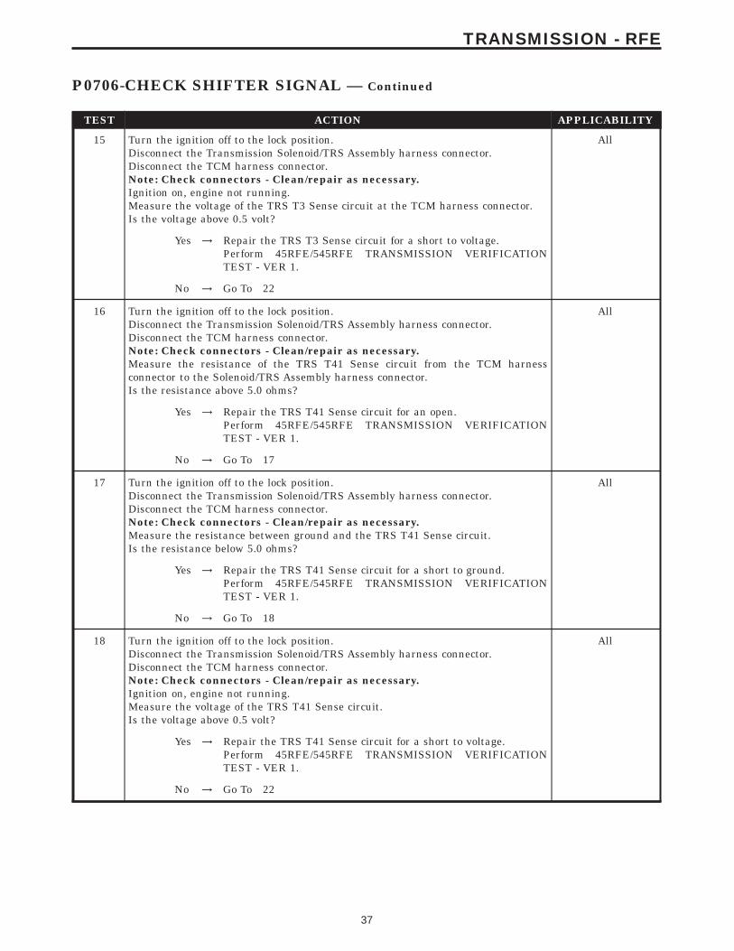
TEST ACTION APPLICABILITY
15 Turn the ignition off to the lock position.Disconnect the Transmission Solenoid/TRS Assembly harness connector.Disconnect the TCM harness connector.Note: Check connectors - Clean/repair as necessary.Ignition on, engine not running.Measure the voltage of the TRS T3 Sense circuit at the TCM harness connector.Is the voltage above 0.5 volt?
All
Yes → Repair the TRS T3 Sense circuit for a short to voltage.Perform 45RFE/545RFE TRANSMISSION VERIFICATIONTEST - VER 1.
No → Go To 22
16 Turn the ignition off to the lock position.Disconnect the Transmission Solenoid/TRS Assembly harness connector.Disconnect the TCM harness connector.Note: Check connectors - Clean/repair as necessary.Measure the resistance of the TRS T41 Sense circuit from the TCM harnessconnector to the Solenoid/TRS Assembly harness connector.Is the resistance above 5.0 ohms?
All
Yes → Repair the TRS T41 Sense circuit for an open.Perform 45RFE/545RFE TRANSMISSION VERIFICATIONTEST - VER 1.
No → Go To 17
17 Turn the ignition off to the lock position.Disconnect the Transmission Solenoid/TRS Assembly harness connector.Disconnect the TCM harness connector.Note: Check connectors - Clean/repair as necessary.Measure the resistance between ground and the TRS T41 Sense circuit.Is the resistance below 5.0 ohms?
All
Yes → Repair the TRS T41 Sense circuit for a short to ground.Perform 45RFE/545RFE TRANSMISSION VERIFICATIONTEST - VER 1.
No → Go To 18
18 Turn the ignition off to the lock position.Disconnect the Transmission Solenoid/TRS Assembly harness connector.Disconnect the TCM harness connector.Note: Check connectors - Clean/repair as necessary.Ignition on, engine not running.Measure the voltage of the TRS T41 Sense circuit.Is the voltage above 0.5 volt?
All
Yes → Repair the TRS T41 Sense circuit for a short to voltage.Perform 45RFE/545RFE TRANSMISSION VERIFICATIONTEST - VER 1.
No → Go To 22
37
TRANSMISSION - RFE
P0706-CHECK SHIFTER SIGNAL — Continued
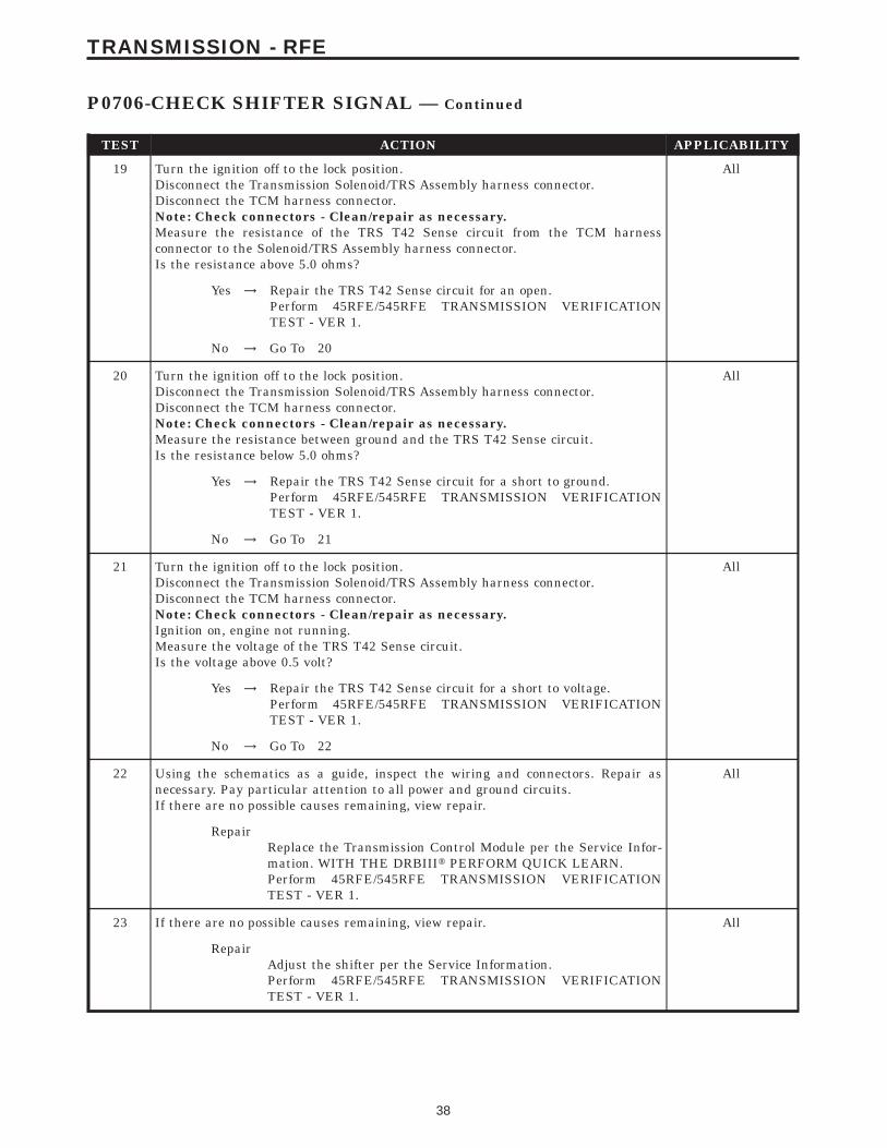
TEST ACTION APPLICABILITY
19 Turn the ignition off to the lock position.Disconnect the Transmission Solenoid/TRS Assembly harness connector.Disconnect the TCM harness connector.Note: Check connectors - Clean/repair as necessary.Measure the resistance of the TRS T42 Sense circuit from the TCM harnessconnector to the Solenoid/TRS Assembly harness connector.Is the resistance above 5.0 ohms?
All
Yes → Repair the TRS T42 Sense circuit for an open.Perform 45RFE/545RFE TRANSMISSION VERIFICATIONTEST - VER 1.
No → Go To 20
20 Turn the ignition off to the lock position.Disconnect the Transmission Solenoid/TRS Assembly harness connector.Disconnect the TCM harness connector.Note: Check connectors - Clean/repair as necessary.Measure the resistance between ground and the TRS T42 Sense circuit.Is the resistance below 5.0 ohms?
All
Yes → Repair the TRS T42 Sense circuit for a short to ground.Perform 45RFE/545RFE TRANSMISSION VERIFICATIONTEST - VER 1.
No → Go To 21
21 Turn the ignition off to the lock position.Disconnect the Transmission Solenoid/TRS Assembly harness connector.Disconnect the TCM harness connector.Note: Check connectors - Clean/repair as necessary.Ignition on, engine not running.Measure the voltage of the TRS T42 Sense circuit.Is the voltage above 0.5 volt?
All
Yes → Repair the TRS T42 Sense circuit for a short to voltage.Perform 45RFE/545RFE TRANSMISSION VERIFICATIONTEST - VER 1.
No → Go To 22
22 Using the schematics as a guide, inspect the wiring and connectors. Repair asnecessary. Pay particular attention to all power and ground circuits.If there are no possible causes remaining, view repair.
All
RepairReplace the Transmission Control Module per the Service Infor-mation. WITH THE DRBIIIt PERFORM QUICK LEARN.Perform 45RFE/545RFE TRANSMISSION VERIFICATIONTEST - VER 1.
23 If there are no possible causes remaining, view repair. All
RepairAdjust the shifter per the Service Information.Perform 45RFE/545RFE TRANSMISSION VERIFICATIONTEST - VER 1.
38
TRANSMISSION - RFE
P0706-CHECK SHIFTER SIGNAL — Continued
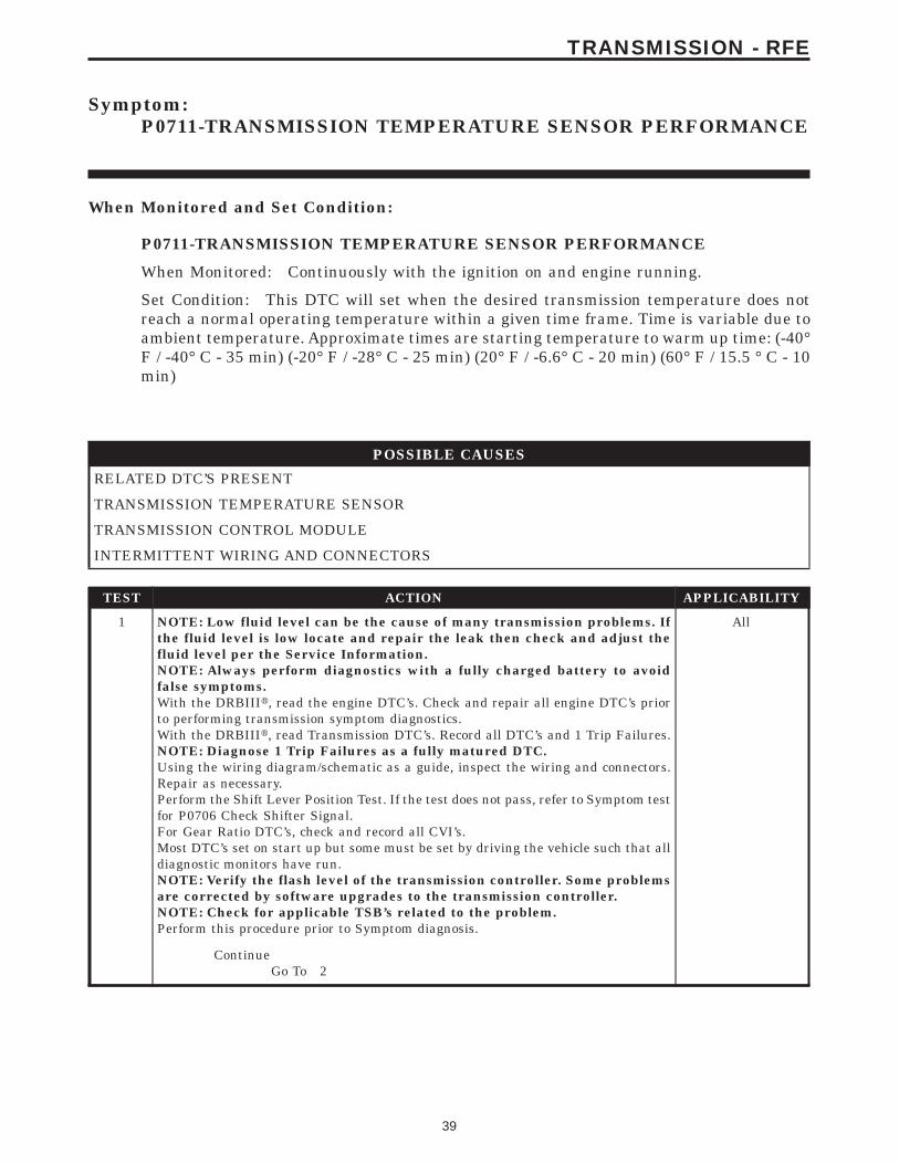
Symptom:P0711-TRANSMISSION TEMPERATURE SENSOR PERFORMANCE
When Monitored and Set Condition:
P0711-TRANSMISSION TEMPERATURE SENSOR PERFORMANCE
When Monitored: Continuously with the ignition on and engine running.
Set Condition: This DTC will set when the desired transmission temperature does notreach a normal operating temperature within a given time frame. Time is variable due toambient temperature. Approximate times are starting temperature to warm up time: (-40°F / -40° C - 35 min) (-20° F / -28° C - 25 min) (20° F / -6.6° C - 20 min) (60° F / 15.5 ° C - 10min)
POSSIBLE CAUSES
RELATED DTC’S PRESENT
TRANSMISSION TEMPERATURE SENSOR
TRANSMISSION CONTROL MODULE
INTERMITTENT WIRING AND CONNECTORS
TEST ACTION APPLICABILITY
1 NOTE: Low fluid level can be the cause of many transmission problems. Ifthe fluid level is low locate and repair the leak then check and adjust thefluid level per the Service Information.NOTE: Always perform diagnostics with a fully charged battery to avoidfalse symptoms.With the DRBIIIt, read the engine DTC’s. Check and repair all engine DTC’s priorto performing transmission symptom diagnostics.With the DRBIIIt, read Transmission DTC’s. Record all DTC’s and 1 Trip Failures.NOTE: Diagnose 1 Trip Failures as a fully matured DTC.Using the wiring diagram/schematic as a guide, inspect the wiring and connectors.Repair as necessary.Perform the Shift Lever Position Test. If the test does not pass, refer to Symptom testfor P0706 Check Shifter Signal.For Gear Ratio DTC’s, check and record all CVI’s.Most DTC’s set on start up but some must be set by driving the vehicle such that alldiagnostic monitors have run.NOTE: Verify the flash level of the transmission controller. Some problemsare corrected by software upgrades to the transmission controller.NOTE: Check for applicable TSB’s related to the problem.Perform this procedure prior to Symptom diagnosis.
All
ContinueGo To 2
39
TRANSMISSION - RFE

TEST ACTION APPLICABILITY
2 With the DRBIIIt, check Transmission DTC’s.Are there any other Transmission Temperature Sensor related DTCs present?
All
Yes → Refer to the Transmission category and perform the appropriatesymptom.Perform 45RFE/545RFE TRANSMISSION VERIFICATIONTEST - VER 1.
No → Go To 3
3 With the DRBIIIt, Check the STARTS SINCE SET counter for P0711.NOTE: This counter only applies to the last DTC set.Is the STARTS SINCE SET counter 2 or less?
All
Yes → Go To 4
No → Go To 7
4 Turn the ignition off to the lock position.Remove the Starter Relay.NOTE: Failure to remove Starter Relay can cause a Transmission - NoResponse condition.Install the Transmission Simulator, Miller tool #8333.Note: Check connectors - Clean/repair as necessary.Ignition on, engine not running.With the Transmission Simulator, turn the Input/Output switch to OFF.With the DRBIIIt, monitor the TRANS TEMP VOLTS while turning the ThermistorVoltage switch to all three positions on the Transmission Simulator.Compare the DRBIIIt readings with the numbers listed on the TransmissionSimulator.Do the readings on the Transmission Simulator match the DRBIIIt readings ± 0.2volts?
All
Yes → Go To 5
No → Go To 6
5 If there are no possible causes remaining, view repair. All
RepairReplace Transmission Solenoid/TRS Assembly per the ServiceInformation.Perform 45RFE/545RFE TRANSMISSION VERIFICATIONTEST - VER 1.
6 Using the schematics as a guide, inspect the wiring and connectors. Repair asnecessary. Pay particular attention to all power and ground circuits.If there are no possible causes remaining, view repair.
All
RepairReplace the Transmission Control Module per the Service Infor-mation. WITH THE DRBIIIt PERFORM QUICK LEARN.Perform 45RFE/545RFE TRANSMISSION VERIFICATIONTEST - VER 1.
40
TRANSMISSION - RFE
P0711-TRANSMISSION TEMPERATURE SENSOR PERFORMANCE —Continued

TEST ACTION APPLICABILITY
7 The conditions necessary to set this DTC are not present at this time.Using the schematics as a guide, inspect the wiring and connectors specific to thiscircuit.Wiggle the wires while checking for shorts and open circuits.With the DRBIIIt, check the EATX DTC EVENT DATA to help identify theconditions in which the DTC was set.Were there any problems found?
All
Yes → Repair as necessary.Perform 45RFE/545RFE TRANSMISSION VERIFICATIONTEST - VER 1.
No → Test Complete.
41
TRANSMISSION - RFE
P0711-TRANSMISSION TEMPERATURE SENSOR PERFORMANCE —Continued

Symptom:P0712-TRANSMISSION TEMPERATURE SENSOR LOW
When Monitored and Set Condition:
P0712-TRANSMISSION TEMPERATURE SENSOR LOW
When Monitored: Continuously with the ignition on and engine running.
Set Condition: The DTC will set when the monitored Temperature Sensor voltage dropsbelow 0.078 volts for the period of 0.45 seconds.
POSSIBLE CAUSES
RELATED DTC’S PRESENT
TRANSMISSION TEMPERATURE SENSOR SIGNAL CIRCUIT SHORT TO GROUND
TRANSMISSION TEMPERATURE SENSOR
TRANSMISSION CONTROL MODULE
INTERMITTENT WIRING AND CONNECTORS
TEST ACTION APPLICABILITY
1 NOTE: Low fluid level can be the cause of many transmission problems. Ifthe fluid level is low locate and repair the leak then check and adjust thefluid level per the Service Information.NOTE: Always perform diagnostics with a fully charged battery to avoidfalse symptoms.With the DRBIIIt, read the engine DTC’s. Check and repair all engine DTC’s priorto performing transmission symptom diagnostics.With the DRBIIIt, read Transmission DTC’s. Record all DTC’s and 1 Trip Failures.NOTE: Diagnose 1 Trip Failures as a fully matured DTC.Using the wiring diagram/schematic as a guide, inspect the wiring and connectors.Repair as necessary.Perform the Shift Lever Position Test. If the test does not pass, refer to Symptom testfor P0706 Check Shifter Signal.For Gear Ratio DTC’s, check and record all CVI’s.Most DTC’s set on start up but some must be set by driving the vehicle such that alldiagnostic monitors have run.NOTE: Verify the flash level of the transmission controller. Some problemsare corrected by software upgrades to the transmission controller.NOTE: Check for applicable TSB’s related to the problem.Perform this procedure prior to Symptom diagnosis.
All
ContinueGo To 2
2 With the DRBIIIt, check Transmission DTC’s.Are there any Speed Sensor DTCs present?
All
Yes → Refer to the Transmission category and perform the appropriatesymptom.Perform 45RFE/545RFE TRANSMISSION VERIFICATIONTEST - VER 1.
No → Go To 3
42
TRANSMISSION - RFE
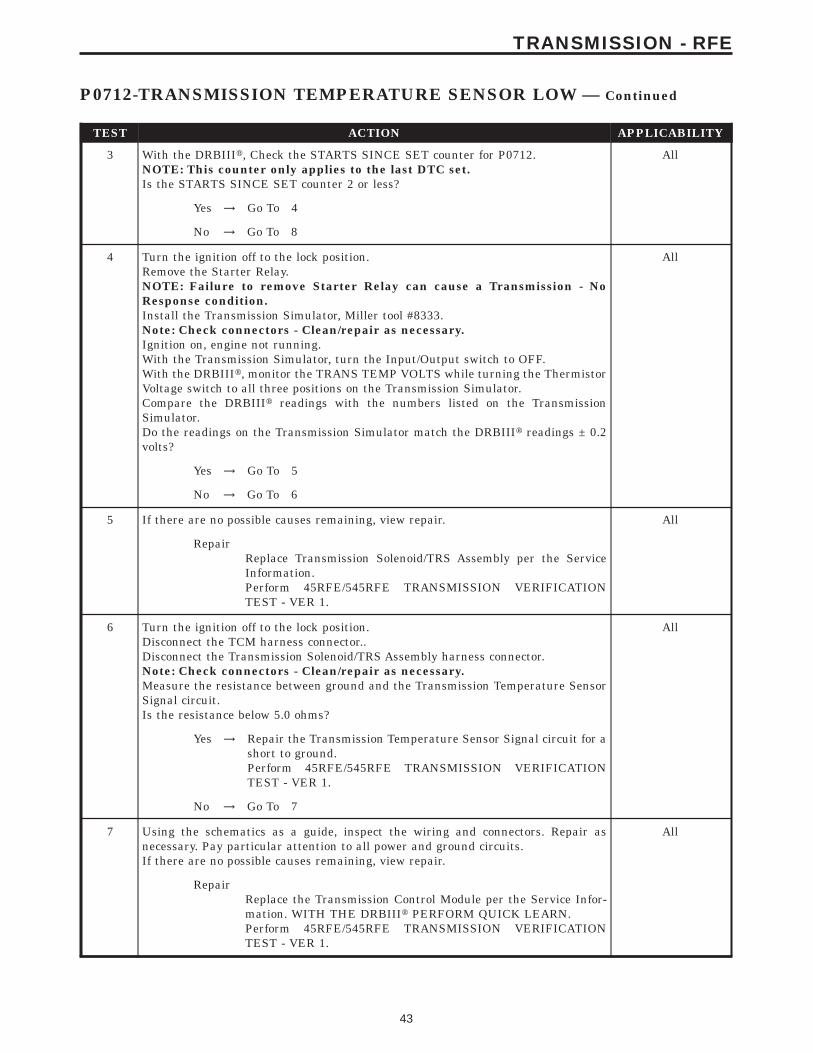
TEST ACTION APPLICABILITY
3 With the DRBIIIt, Check the STARTS SINCE SET counter for P0712.NOTE: This counter only applies to the last DTC set.Is the STARTS SINCE SET counter 2 or less?
All
Yes → Go To 4
No → Go To 8
4 Turn the ignition off to the lock position.Remove the Starter Relay.NOTE: Failure to remove Starter Relay can cause a Transmission - NoResponse condition.Install the Transmission Simulator, Miller tool #8333.Note: Check connectors - Clean/repair as necessary.Ignition on, engine not running.With the Transmission Simulator, turn the Input/Output switch to OFF.With the DRBIIIt, monitor the TRANS TEMP VOLTS while turning the ThermistorVoltage switch to all three positions on the Transmission Simulator.Compare the DRBIIIt readings with the numbers listed on the TransmissionSimulator.Do the readings on the Transmission Simulator match the DRBIIIt readings ± 0.2volts?
All
Yes → Go To 5
No → Go To 6
5 If there are no possible causes remaining, view repair. All
RepairReplace Transmission Solenoid/TRS Assembly per the ServiceInformation.Perform 45RFE/545RFE TRANSMISSION VERIFICATIONTEST - VER 1.
6 Turn the ignition off to the lock position.Disconnect the TCM harness connector..Disconnect the Transmission Solenoid/TRS Assembly harness connector.Note: Check connectors - Clean/repair as necessary.Measure the resistance between ground and the Transmission Temperature SensorSignal circuit.Is the resistance below 5.0 ohms?
All
Yes → Repair the Transmission Temperature Sensor Signal circuit for ashort to ground.Perform 45RFE/545RFE TRANSMISSION VERIFICATIONTEST - VER 1.
No → Go To 7
7 Using the schematics as a guide, inspect the wiring and connectors. Repair asnecessary. Pay particular attention to all power and ground circuits.If there are no possible causes remaining, view repair.
All
RepairReplace the Transmission Control Module per the Service Infor-mation. WITH THE DRBIIIt PERFORM QUICK LEARN.Perform 45RFE/545RFE TRANSMISSION VERIFICATIONTEST - VER 1.
43
TRANSMISSION - RFE
P0712-TRANSMISSION TEMPERATURE SENSOR LOW — Continued
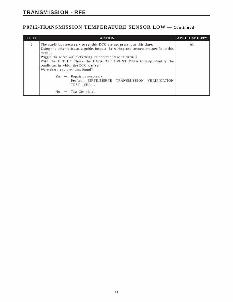
TEST ACTION APPLICABILITY
8 The conditions necessary to set this DTC are not present at this time.Using the schematics as a guide, inspect the wiring and connectors specific to thiscircuit.Wiggle the wires while checking for shorts and open circuits.With the DRBIIIt, check the EATX DTC EVENT DATA to help identify theconditions in which the DTC was set.Were there any problems found?
All
Yes → Repair as necessary.Perform 45RFE/545RFE TRANSMISSION VERIFICATIONTEST - VER 1.
No → Test Complete.
44
TRANSMISSION - RFE
P0712-TRANSMISSION TEMPERATURE SENSOR LOW — Continued
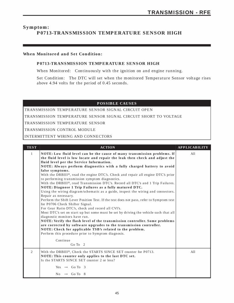
Symptom:P0713-TRANSMISSION TEMPERATURE SENSOR HIGH
When Monitored and Set Condition:
P0713-TRANSMISSION TEMPERATURE SENSOR HIGH
When Monitored: Continuously with the ignition on and engine running.
Set Condition: The DTC will set when the monitored Temperature Sensor voltage risesabove 4.94 volts for the period of 0.45 seconds.
POSSIBLE CAUSES
TRANSMISSION TEMPERATURE SENSOR SIGNAL CIRCUIT OPEN
TRANSMISSION TEMPERATURE SENSOR SIGNAL CIRCUIT SHORT TO VOLTAGE
TRANSMISSION TEMPERATURE SENSOR
TRANSMISSION CONTROL MODULE
INTERMITTENT WIRING AND CONNECTORS
TEST ACTION APPLICABILITY
1 NOTE: Low fluid level can be the cause of many transmission problems. Ifthe fluid level is low locate and repair the leak then check and adjust thefluid level per the Service Information.NOTE: Always perform diagnostics with a fully charged battery to avoidfalse symptoms.With the DRBIIIt, read the engine DTC’s. Check and repair all engine DTC’s priorto performing transmission symptom diagnostics.With the DRBIIIt, read Transmission DTC’s. Record all DTC’s and 1 Trip Failures.NOTE: Diagnose 1 Trip Failures as a fully matured DTC.Using the wiring diagram/schematic as a guide, inspect the wiring and connectors.Repair as necessary.Perform the Shift Lever Position Test. If the test does not pass, refer to Symptom testfor P0706 Check Shifter Signal.For Gear Ratio DTC’s, check and record all CVI’s.Most DTC’s set on start up but some must be set by driving the vehicle such that alldiagnostic monitors have run.NOTE: Verify the flash level of the transmission controller. Some problemsare corrected by software upgrades to the transmission controller.NOTE: Check for applicable TSB’s related to the problem.Perform this procedure prior to Symptom diagnosis.
All
ContinueGo To 2
2 With the DRBIIIt, Check the STARTS SINCE SET counter for P0713.NOTE: This counter only applies to the last DTC set.Is the STARTS SINCE SET counter 2 or less?
All
Yes → Go To 3
No → Go To 8
45
TRANSMISSION - RFE
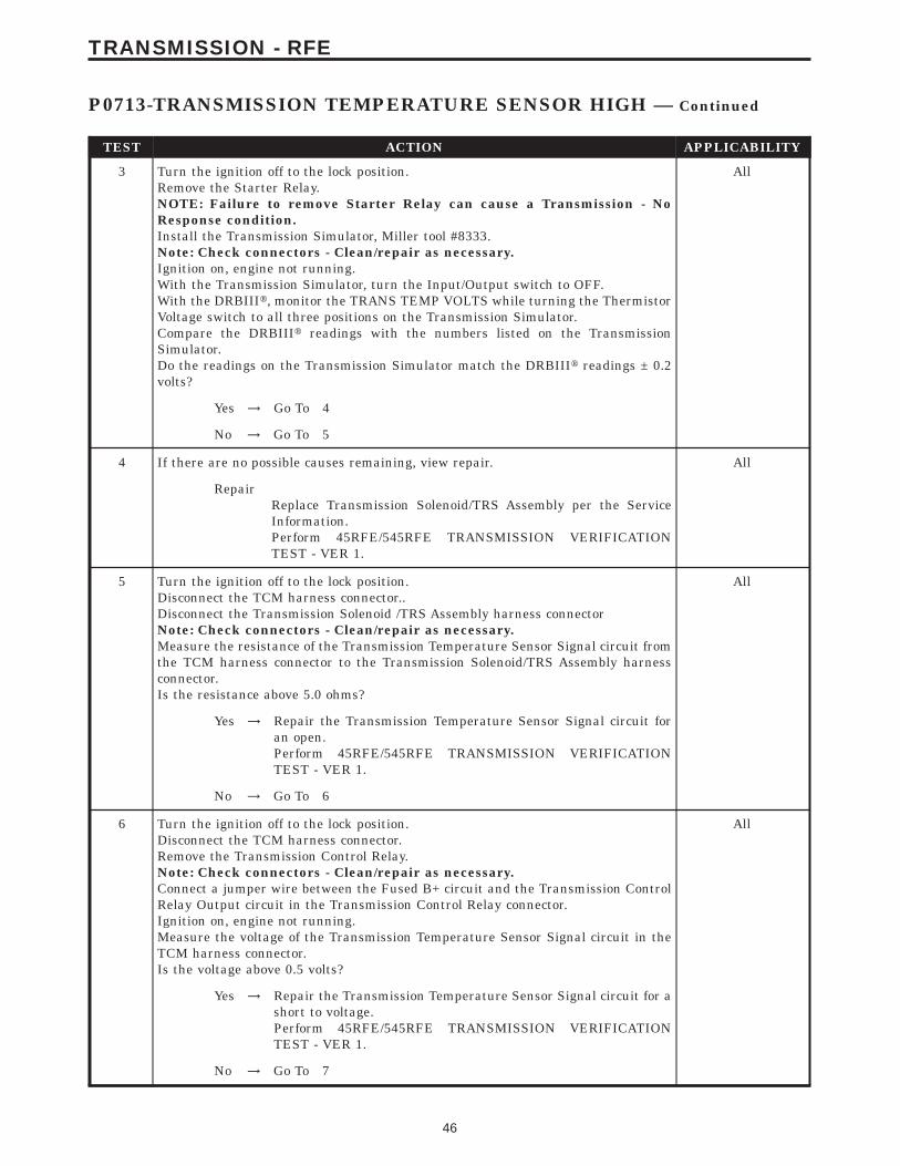
TEST ACTION APPLICABILITY
3 Turn the ignition off to the lock position.Remove the Starter Relay.NOTE: Failure to remove Starter Relay can cause a Transmission - NoResponse condition.Install the Transmission Simulator, Miller tool #8333.Note: Check connectors - Clean/repair as necessary.Ignition on, engine not running.With the Transmission Simulator, turn the Input/Output switch to OFF.With the DRBIIIt, monitor the TRANS TEMP VOLTS while turning the ThermistorVoltage switch to all three positions on the Transmission Simulator.Compare the DRBIIIt readings with the numbers listed on the TransmissionSimulator.Do the readings on the Transmission Simulator match the DRBIIIt readings ± 0.2volts?
All
Yes → Go To 4
No → Go To 5
4 If there are no possible causes remaining, view repair. All
RepairReplace Transmission Solenoid/TRS Assembly per the ServiceInformation.Perform 45RFE/545RFE TRANSMISSION VERIFICATIONTEST - VER 1.
5 Turn the ignition off to the lock position.Disconnect the TCM harness connector..Disconnect the Transmission Solenoid /TRS Assembly harness connectorNote: Check connectors - Clean/repair as necessary.Measure the resistance of the Transmission Temperature Sensor Signal circuit fromthe TCM harness connector to the Transmission Solenoid/TRS Assembly harnessconnector.Is the resistance above 5.0 ohms?
All
Yes → Repair the Transmission Temperature Sensor Signal circuit foran open.Perform 45RFE/545RFE TRANSMISSION VERIFICATIONTEST - VER 1.
No → Go To 6
6 Turn the ignition off to the lock position.Disconnect the TCM harness connector.Remove the Transmission Control Relay.Note: Check connectors - Clean/repair as necessary.Connect a jumper wire between the Fused B+ circuit and the Transmission ControlRelay Output circuit in the Transmission Control Relay connector.Ignition on, engine not running.Measure the voltage of the Transmission Temperature Sensor Signal circuit in theTCM harness connector.Is the voltage above 0.5 volts?
All
Yes → Repair the Transmission Temperature Sensor Signal circuit for ashort to voltage.Perform 45RFE/545RFE TRANSMISSION VERIFICATIONTEST - VER 1.
No → Go To 7
46
TRANSMISSION - RFE
P0713-TRANSMISSION TEMPERATURE SENSOR HIGH — Continued

TEST ACTION APPLICABILITY
7 Using the schematics as a guide, inspect the wiring and connectors. Repair asnecessary. Pay particular attention to all power and ground circuits.If there are no possible causes remaining, view repair.
All
RepairReplace the Transmission Control Module per the Service Infor-mation. WITH THE DRBIIIt PERFORM QUICK LEARN.Perform 45RFE/545RFE TRANSMISSION VERIFICATIONTEST - VER 1.
8 The conditions necessary to set this DTC are not present at this time.Using the schematics as a guide, inspect the wiring and connectors specific to thiscircuit.Wiggle the wires while checking for shorts and open circuits.With the DRBIIIt, check the EATX DTC EVENT DATA to help identify theconditions in which the DTC was set.Were there any problems found?
All
Yes → Repair as necessary.Perform 45RFE/545RFE TRANSMISSION VERIFICATIONTEST - VER 1.
No → Test Complete.
47
TRANSMISSION - RFE
P0713-TRANSMISSION TEMPERATURE SENSOR HIGH — Continued

Symptom:P0714-TRANSMISSION TEMPERATURE SENSOR INTERMITTENT
When Monitored and Set Condition:
P0714-TRANSMISSION TEMPERATURE SENSOR INTERMITTENT
When Monitored: Continuously with the ignition on and engine running.
Set Condition: The DTC will set when the monitored Temperature Sensor voltagefluctuates or changes abruptly within a predetermined period of time.
POSSIBLE CAUSES
RELATED DTC’S PRESENT
TRANSMISSION TEMPERATURE SENSOR
TRANSMISSION CONTROL MODULE
INTERMITTENT WIRING AND CONNECTORS
TEST ACTION APPLICABILITY
1 NOTE: Low fluid level can be the cause of many transmission problems. Ifthe fluid level is low locate and repair the leak then check and adjust thefluid level per the Service Information.NOTE: Always perform diagnostics with a fully charged battery to avoidfalse symptoms.With the DRBIIIt, read the engine DTC’s. Check and repair all engine DTC’s priorto performing transmission symptom diagnostics.With the DRBIIIt, read Transmission DTC’s. Record all DTC’s and 1 Trip Failures.NOTE: Diagnose 1 Trip Failures as a fully matured DTC.Using the wiring diagram/schematic as a guide, inspect the wiring and connectors.Repair as necessary.Perform the Shift Lever Position Test. If the test does not pass, refer to Symptom testfor P0706 Check Shifter Signal.For Gear Ratio DTC’s, check and record all CVI’s.Most DTC’s set on start up but some must be set by driving the vehicle such that alldiagnostic monitors have run.NOTE: Verify the flash level of the transmission controller. Some problemsare corrected by software upgrades to the transmission controller.NOTE: Check for applicable TSB’s related to the problem.Perform this procedure prior to Symptom diagnosis.
All
ContinueGo To 2
2 With the DRBIIIt, check Transmission DTC’s.Are there any Speed Sensor and/or other Temperature Sensor DTCs present?
All
Yes → Refer to the Transmission category and perform the appropriatesymptom.Perform 45RFE/545RFE TRANSMISSION VERIFICATIONTEST - VER 1.
No → Go To 3
48
TRANSMISSION - RFE
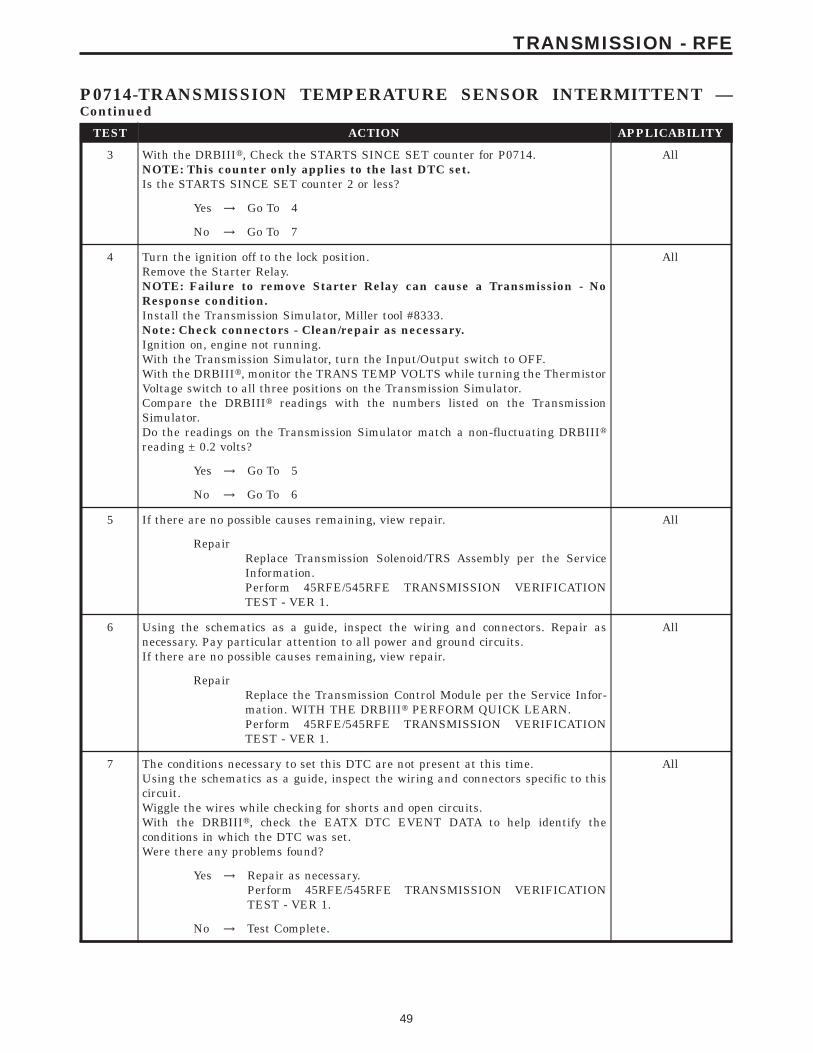
TEST ACTION APPLICABILITY
3 With the DRBIIIt, Check the STARTS SINCE SET counter for P0714.NOTE: This counter only applies to the last DTC set.Is the STARTS SINCE SET counter 2 or less?
All
Yes → Go To 4
No → Go To 7
4 Turn the ignition off to the lock position.Remove the Starter Relay.NOTE: Failure to remove Starter Relay can cause a Transmission - NoResponse condition.Install the Transmission Simulator, Miller tool #8333.Note: Check connectors - Clean/repair as necessary.Ignition on, engine not running.With the Transmission Simulator, turn the Input/Output switch to OFF.With the DRBIIIt, monitor the TRANS TEMP VOLTS while turning the ThermistorVoltage switch to all three positions on the Transmission Simulator.Compare the DRBIIIt readings with the numbers listed on the TransmissionSimulator.Do the readings on the Transmission Simulator match a non-fluctuating DRBIIItreading ± 0.2 volts?
All
Yes → Go To 5
No → Go To 6
5 If there are no possible causes remaining, view repair. All
RepairReplace Transmission Solenoid/TRS Assembly per the ServiceInformation.Perform 45RFE/545RFE TRANSMISSION VERIFICATIONTEST - VER 1.
6 Using the schematics as a guide, inspect the wiring and connectors. Repair asnecessary. Pay particular attention to all power and ground circuits.If there are no possible causes remaining, view repair.
All
RepairReplace the Transmission Control Module per the Service Infor-mation. WITH THE DRBIIIt PERFORM QUICK LEARN.Perform 45RFE/545RFE TRANSMISSION VERIFICATIONTEST - VER 1.
7 The conditions necessary to set this DTC are not present at this time.Using the schematics as a guide, inspect the wiring and connectors specific to thiscircuit.Wiggle the wires while checking for shorts and open circuits.With the DRBIIIt, check the EATX DTC EVENT DATA to help identify theconditions in which the DTC was set.Were there any problems found?
All
Yes → Repair as necessary.Perform 45RFE/545RFE TRANSMISSION VERIFICATIONTEST - VER 1.
No → Test Complete.
49
TRANSMISSION - RFE
P0714-TRANSMISSION TEMPERATURE SENSOR INTERMITTENT —Continued
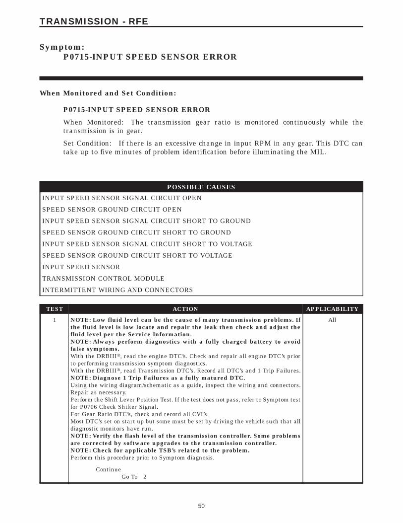
Symptom:P0715-INPUT SPEED SENSOR ERROR
When Monitored and Set Condition:
P0715-INPUT SPEED SENSOR ERROR
When Monitored: The transmission gear ratio is monitored continuously while thetransmission is in gear.
Set Condition: If there is an excessive change in input RPM in any gear. This DTC cantake up to five minutes of problem identification before illuminating the MIL.
POSSIBLE CAUSES
INPUT SPEED SENSOR SIGNAL CIRCUIT OPEN
SPEED SENSOR GROUND CIRCUIT OPEN
INPUT SPEED SENSOR SIGNAL CIRCUIT SHORT TO GROUND
SPEED SENSOR GROUND CIRCUIT SHORT TO GROUND
INPUT SPEED SENSOR SIGNAL CIRCUIT SHORT TO VOLTAGE
SPEED SENSOR GROUND CIRCUIT SHORT TO VOLTAGE
INPUT SPEED SENSOR
TRANSMISSION CONTROL MODULE
INTERMITTENT WIRING AND CONNECTORS
TEST ACTION APPLICABILITY
1 NOTE: Low fluid level can be the cause of many transmission problems. Ifthe fluid level is low locate and repair the leak then check and adjust thefluid level per the Service Information.NOTE: Always perform diagnostics with a fully charged battery to avoidfalse symptoms.With the DRBIIIt, read the engine DTC’s. Check and repair all engine DTC’s priorto performing transmission symptom diagnostics.With the DRBIIIt, read Transmission DTC’s. Record all DTC’s and 1 Trip Failures.NOTE: Diagnose 1 Trip Failures as a fully matured DTC.Using the wiring diagram/schematic as a guide, inspect the wiring and connectors.Repair as necessary.Perform the Shift Lever Position Test. If the test does not pass, refer to Symptom testfor P0706 Check Shifter Signal.For Gear Ratio DTC’s, check and record all CVI’s.Most DTC’s set on start up but some must be set by driving the vehicle such that alldiagnostic monitors have run.NOTE: Verify the flash level of the transmission controller. Some problemsare corrected by software upgrades to the transmission controller.NOTE: Check for applicable TSB’s related to the problem.Perform this procedure prior to Symptom diagnosis.
All
ContinueGo To 2
50
TRANSMISSION - RFE

TEST ACTION APPLICABILITY
2 Start the engine in park.With the DRBIIIt, observe the Input Speed Sensor Reading.Is the Input Speed Sensor Reading below 400 RPM?
All
Yes → Go To 3
No → Go To 12
3 Turn the ignition off to the lock position.Remove the Starter Relay.NOTE: Failure to remove the Starter Relay can cause a Transmission - NoResponse condition.Install Transmission Simulator Miller tool #8333.Note: Check connectors - Clean/repair as necessary.Ignition on, engine not running.With the Transmission Simulator, set the 9Input/Output Speed9 switch to 9ON9 andthe rotary switch to the 93000/10009 position.With the DRBIIIt, observe the Input and Output Speed Sensor readings.Does the input speed read 3000 RPM and the Output speed read 1000 RPM ± 50RPM?
All
Yes → Go To 4
No → Go To 5
4 If there are no possible causes remaining, view repair. All
RepairReplace the Input Speed Sensor per the Service Information.Perform 45RFE/545RFE TRANSMISSION VERIFICATIONTEST - VER 1.
5 Turn the ignition off to the lock position.Disconnect the TCM harness connector.Disconnect the Input Speed Sensor harness connector.Note: Check connectors - Clean/repair as necessary.Measure the resistance of the Input Speed Sensor Signal circuit from the TCMharness connector to the Input Speed Sensor harness connector.Is the resistance above 5.0 ohms?
All
Yes → Repair the Input Speed Sensor Signal circuit for an open.Perform 45RFE/545RFE TRANSMISSION VERIFICATIONTEST - VER 1.
No → Go To 6
6 Turn the ignition off to the lock position.Disconnect the TCM harness connector.Disconnect the Input Speed Sensor harness connector.Note: Check connectors - Clean/repair as necessary.Measure the resistance between ground and the Input Speed Sensor Signal circuit.Is the resistance Below 5.0 ohms?
All
Yes → Repair the Input Speed Sensor Signal circuit for a short toground.Perform 45RFE/545RFE TRANSMISSION VERIFICATIONTEST - VER 1.
No → Go To 7
51
TRANSMISSION - RFE
P0715-INPUT SPEED SENSOR ERROR — Continued
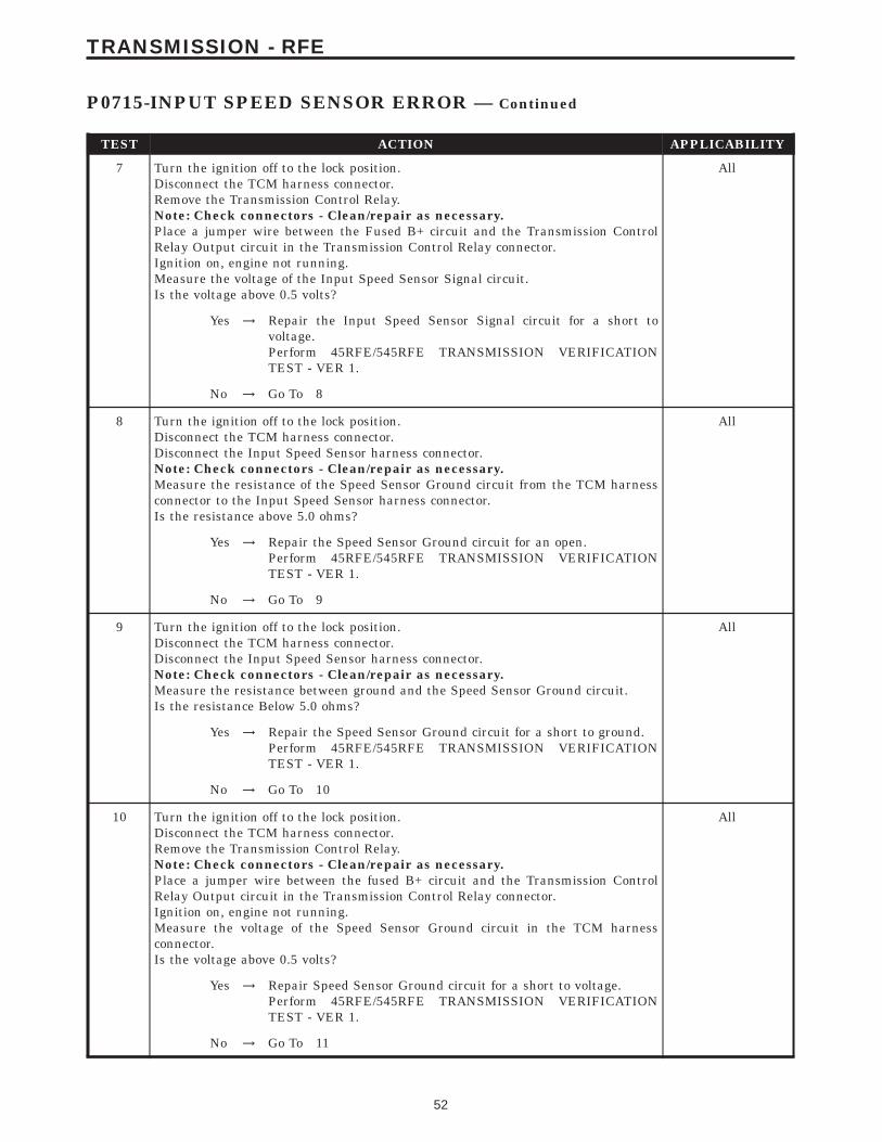
TEST ACTION APPLICABILITY
7 Turn the ignition off to the lock position.Disconnect the TCM harness connector.Remove the Transmission Control Relay.Note: Check connectors - Clean/repair as necessary.Place a jumper wire between the Fused B+ circuit and the Transmission ControlRelay Output circuit in the Transmission Control Relay connector.Ignition on, engine not running.Measure the voltage of the Input Speed Sensor Signal circuit.Is the voltage above 0.5 volts?
All
Yes → Repair the Input Speed Sensor Signal circuit for a short tovoltage.Perform 45RFE/545RFE TRANSMISSION VERIFICATIONTEST - VER 1.
No → Go To 8
8 Turn the ignition off to the lock position.Disconnect the TCM harness connector.Disconnect the Input Speed Sensor harness connector.Note: Check connectors - Clean/repair as necessary.Measure the resistance of the Speed Sensor Ground circuit from the TCM harnessconnector to the Input Speed Sensor harness connector.Is the resistance above 5.0 ohms?
All
Yes → Repair the Speed Sensor Ground circuit for an open.Perform 45RFE/545RFE TRANSMISSION VERIFICATIONTEST - VER 1.
No → Go To 9
9 Turn the ignition off to the lock position.Disconnect the TCM harness connector.Disconnect the Input Speed Sensor harness connector.Note: Check connectors - Clean/repair as necessary.Measure the resistance between ground and the Speed Sensor Ground circuit.Is the resistance Below 5.0 ohms?
All
Yes → Repair the Speed Sensor Ground circuit for a short to ground.Perform 45RFE/545RFE TRANSMISSION VERIFICATIONTEST - VER 1.
No → Go To 10
10 Turn the ignition off to the lock position.Disconnect the TCM harness connector.Remove the Transmission Control Relay.Note: Check connectors - Clean/repair as necessary.Place a jumper wire between the fused B+ circuit and the Transmission ControlRelay Output circuit in the Transmission Control Relay connector.Ignition on, engine not running.Measure the voltage of the Speed Sensor Ground circuit in the TCM harnessconnector.Is the voltage above 0.5 volts?
All
Yes → Repair Speed Sensor Ground circuit for a short to voltage.Perform 45RFE/545RFE TRANSMISSION VERIFICATIONTEST - VER 1.
No → Go To 11
52
TRANSMISSION - RFE
P0715-INPUT SPEED SENSOR ERROR — Continued

TEST ACTION APPLICABILITY
11 Using the schematics as a guide, inspect the wiring and connectors. Repair asnecessary. Pay particular attention to all power and ground circuits.If there are no possible causes remaining, view repair.
All
RepairReplace the Transmission Control Module per the Service Infor-mation. WITH THE DRBIIIt PERFORM QUICK LEARN.Perform 45RFE/545RFE TRANSMISSION VERIFICATIONTEST - VER 1.
12 The conditions necessary to set this DTC are not present at this time.Using the schematics as a guide, inspect the wiring and connectors specific to thiscircuit.Wiggle the wires while checking for shorts and open circuits.With the DRBIIIt, check the EATX DTC EVENT DATA to help identify theconditions in which the DTC was set.Were there any problems found?
All
Yes → Repair as necessary.Perform 45RFE/545RFE TRANSMISSION VERIFICATIONTEST - VER 1.
No → Test Complete.
53
TRANSMISSION - RFE
P0715-INPUT SPEED SENSOR ERROR — Continued
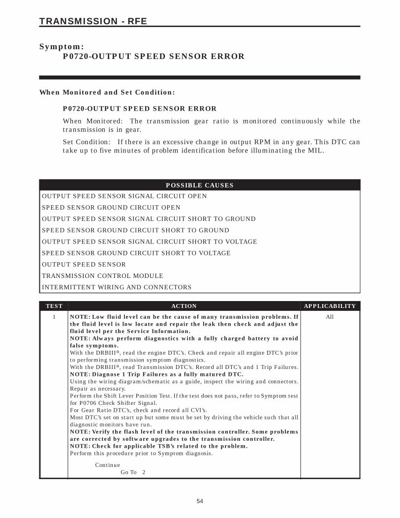
Symptom:P0720-OUTPUT SPEED SENSOR ERROR
When Monitored and Set Condition:
P0720-OUTPUT SPEED SENSOR ERROR
When Monitored: The transmission gear ratio is monitored continuously while thetransmission is in gear.
Set Condition: If there is an excessive change in output RPM in any gear. This DTC cantake up to five minutes of problem identification before illuminating the MIL.
POSSIBLE CAUSES
OUTPUT SPEED SENSOR SIGNAL CIRCUIT OPEN
SPEED SENSOR GROUND CIRCUIT OPEN
OUTPUT SPEED SENSOR SIGNAL CIRCUIT SHORT TO GROUND
SPEED SENSOR GROUND CIRCUIT SHORT TO GROUND
OUTPUT SPEED SENSOR SIGNAL CIRCUIT SHORT TO VOLTAGE
SPEED SENSOR GROUND CIRCUIT SHORT TO VOLTAGE
OUTPUT SPEED SENSOR
TRANSMISSION CONTROL MODULE
INTERMITTENT WIRING AND CONNECTORS
TEST ACTION APPLICABILITY
1 NOTE: Low fluid level can be the cause of many transmission problems. Ifthe fluid level is low locate and repair the leak then check and adjust thefluid level per the Service Information.NOTE: Always perform diagnostics with a fully charged battery to avoidfalse symptoms.With the DRBIIIt, read the engine DTC’s. Check and repair all engine DTC’s priorto performing transmission symptom diagnostics.With the DRBIIIt, read Transmission DTC’s. Record all DTC’s and 1 Trip Failures.NOTE: Diagnose 1 Trip Failures as a fully matured DTC.Using the wiring diagram/schematic as a guide, inspect the wiring and connectors.Repair as necessary.Perform the Shift Lever Position Test. If the test does not pass, refer to Symptom testfor P0706 Check Shifter Signal.For Gear Ratio DTC’s, check and record all CVI’s.Most DTC’s set on start up but some must be set by driving the vehicle such that alldiagnostic monitors have run.NOTE: Verify the flash level of the transmission controller. Some problemsare corrected by software upgrades to the transmission controller.NOTE: Check for applicable TSB’s related to the problem.Perform this procedure prior to Symptom diagnosis.
All
ContinueGo To 2
54
TRANSMISSION - RFE

TEST ACTION APPLICABILITY
2 Turn the ignition off to the lock position.CAUTION: Properly support the vehicle and raise all drive wheels off theground.Start the engine in park.Place the transmission gear selector in drive, release foot from brake.WARNING: BE SURE TO KEEP HANDS AND FEET CLEAR OF ROTATINGWHEELS.With the DRBIIIt, monitor the Output Speed Sensor RPM.Is the Output Speed Sensor RPM below 100 RPM?
All
Yes → Go To 3
No → Go To 12
3 Turn the ignition off to the lock position.Remove the Starter Relay.NOTE: Failure to remove the Starter Relay can cause a Transmission - NoResponse condition.Install the Transmission Simulator, Miller tool #8333.Note: Check connectors - Clean/repair as necessary.Ignition on, engine not running.With the Transmission Simulator, set the 9Input/Output Speed9 switch to 9ON9 andthe rotary switch to the 93000/10009 position.With the DRBIIIt, read the Input and Output Speed Sensor readings.Does the Input Speed read 3000 RPM and the Output Speed read 1000 RPM, ± 50RPM?
All
Yes → Go To 4
No → Go To 5
4 If there are no possible causes remaining, view repair. All
RepairReplace the Output Speed Sensor per the Service Information.Perform 45RFE/545RFE TRANSMISSION VERIFICATIONTEST - VER 1.
5 Turn the ignition off to the lock position.Disconnect the TCM harness connector.Disconnect the Output Speed Sensor harness connector.Note: Check connectors - Clean/repair as necessary.Measure the resistance of the Output Speed Sensor Signal circuit from the TCMharness connector to the Output Speed Sensor harness connector.Is the resistance above 5.0 ohms?
All
Yes → Repair the Output Speed Sensor Signal circuit for an open.Perform 45RFE/545RFE TRANSMISSION VERIFICATIONTEST - VER 1.
No → Go To 6
55
TRANSMISSION - RFE
P0720-OUTPUT SPEED SENSOR ERROR — Continued
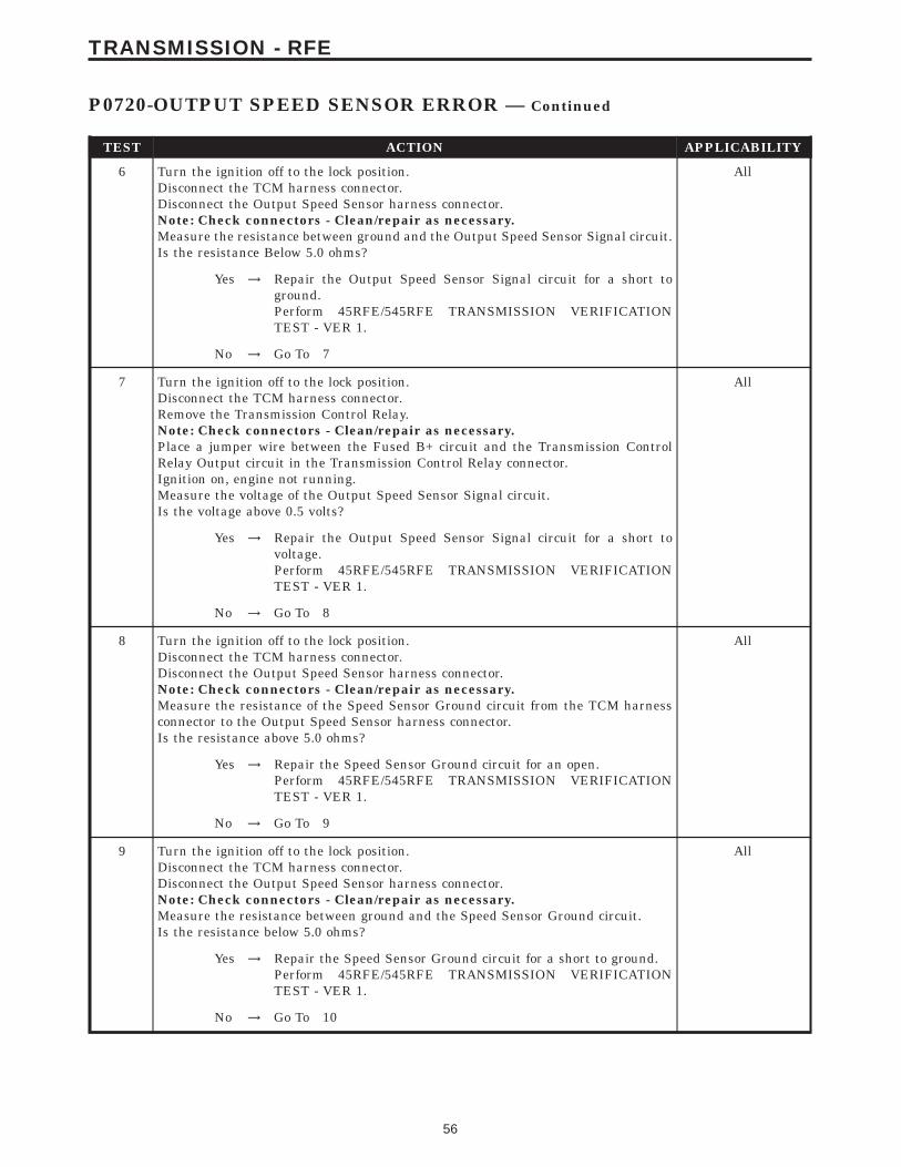
TEST ACTION APPLICABILITY
6 Turn the ignition off to the lock position.Disconnect the TCM harness connector.Disconnect the Output Speed Sensor harness connector.Note: Check connectors - Clean/repair as necessary.Measure the resistance between ground and the Output Speed Sensor Signal circuit.Is the resistance Below 5.0 ohms?
All
Yes → Repair the Output Speed Sensor Signal circuit for a short toground.Perform 45RFE/545RFE TRANSMISSION VERIFICATIONTEST - VER 1.
No → Go To 7
7 Turn the ignition off to the lock position.Disconnect the TCM harness connector.Remove the Transmission Control Relay.Note: Check connectors - Clean/repair as necessary.Place a jumper wire between the Fused B+ circuit and the Transmission ControlRelay Output circuit in the Transmission Control Relay connector.Ignition on, engine not running.Measure the voltage of the Output Speed Sensor Signal circuit.Is the voltage above 0.5 volts?
All
Yes → Repair the Output Speed Sensor Signal circuit for a short tovoltage.Perform 45RFE/545RFE TRANSMISSION VERIFICATIONTEST - VER 1.
No → Go To 8
8 Turn the ignition off to the lock position.Disconnect the TCM harness connector.Disconnect the Output Speed Sensor harness connector.Note: Check connectors - Clean/repair as necessary.Measure the resistance of the Speed Sensor Ground circuit from the TCM harnessconnector to the Output Speed Sensor harness connector.Is the resistance above 5.0 ohms?
All
Yes → Repair the Speed Sensor Ground circuit for an open.Perform 45RFE/545RFE TRANSMISSION VERIFICATIONTEST - VER 1.
No → Go To 9
9 Turn the ignition off to the lock position.Disconnect the TCM harness connector.Disconnect the Output Speed Sensor harness connector.Note: Check connectors - Clean/repair as necessary.Measure the resistance between ground and the Speed Sensor Ground circuit.Is the resistance below 5.0 ohms?
All
Yes → Repair the Speed Sensor Ground circuit for a short to ground.Perform 45RFE/545RFE TRANSMISSION VERIFICATIONTEST - VER 1.
No → Go To 10
56
TRANSMISSION - RFE
P0720-OUTPUT SPEED SENSOR ERROR — Continued

TEST ACTION APPLICABILITY
10 Turn the ignition off to the lock position.Disconnect the TCM harness connector.Remove the Transmission Control Relay.Note: Check connectors - Clean/repair as necessary.Place a jumper wire between the Fused B+ circuit and Transmission Control RelayOutput circuit in the Transmission Control Relay connector.Ignition on, engine not running.Measure the voltage of the Speed Sensor Ground circuit.Is the voltage above 0.5 volts?
All
Yes → Repair the Speed Sensor Ground circuit for a short to voltage.Perform 45RFE/545RFE TRANSMISSION VERIFICATIONTEST - VER 1.
No → Go To 11
11 Using the schematics as a guide, inspect the wiring and connectors. Repair asnecessary. Pay particular attention to all power and ground circuits.If there are no possible causes remaining, view repair.
All
RepairReplace the Transmission Control Module per the Service Infor-mation. WITH THE DRBIIIt PERFORM QUICK LEARN.Perform 45RFE/545RFE TRANSMISSION VERIFICATIONTEST - VER 1.
12 The conditions necessary to set this DTC are not present at this time.Using the schematics as a guide, inspect the wiring and connectors specific to thiscircuit.Wiggle the wires while checking for shorts and open circuits.With the DRBIIIt, check the EATX DTC EVENT DATA to help identify theconditions in which the DTC was set.Were there any problems found?
All
Yes → Repair as necessary.Perform 45RFE/545RFE TRANSMISSION VERIFICATIONTEST - VER 1.
No → Test Complete.
57
TRANSMISSION - RFE
P0720-OUTPUT SPEED SENSOR ERROR — Continued

Symptom:P0725-ENGINE SPEED SENSOR CIRCUIT - DIESEL
When Monitored and Set Condition:
P0725-ENGINE SPEED SENSOR CIRCUIT - DIESEL
When Monitored: Continuously with engine running.
Set Condition: The DTC will set when the Transmission Control Module (TCM) senses aengine RPM less than 400 with the engine running for at least 2 seconds. RPM informationis transferred over the communication bus from the ECM. This DTC can take up to fiveminutes of problem identification before illuminating the MIL.
POSSIBLE CAUSES
ENGINE SPEED SIGNAL CIRCUIT OPEN
ENGINE SPEED SIGNAL CIRCUIT SHORTED GROUND
ENGINE SPEED SIGNAL CIRCUIT SHORT TO VOLTAGE
TRANSMISSION CONTROL MODULE
ENGINE CONTROL MODULE
INTERMITTENT WIRING AND CONNECTORS
TEST ACTION APPLICABILITY
1 With the DRBIIIt, Check the STARTS SINCE SET counter.NOTE: This counter only applies to the last DTC set.Is the STARTS SINCE SET set at 0?
All
Yes → Go To 2
No → Go To 7
2 Turn the ignition off to the lock position.Disconnect the TCM harness connector.Disconnect the ECM harness connector.Note: Check connectors - Clean/repair as necessary.Measure the resistance of the Engine Speed Signal circuit from the TCM harnessconnector to the ECM harness connector.Is the resistance above 5.0 ohms?
All
Yes → Repair the Engine Speed Signal Circuit circuit for an open.Perform 45RFE/545RFE TRANSMISSION VERIFICATIONTEST - VER 1.
No → Go To 3
58
TRANSMISSION - RFE
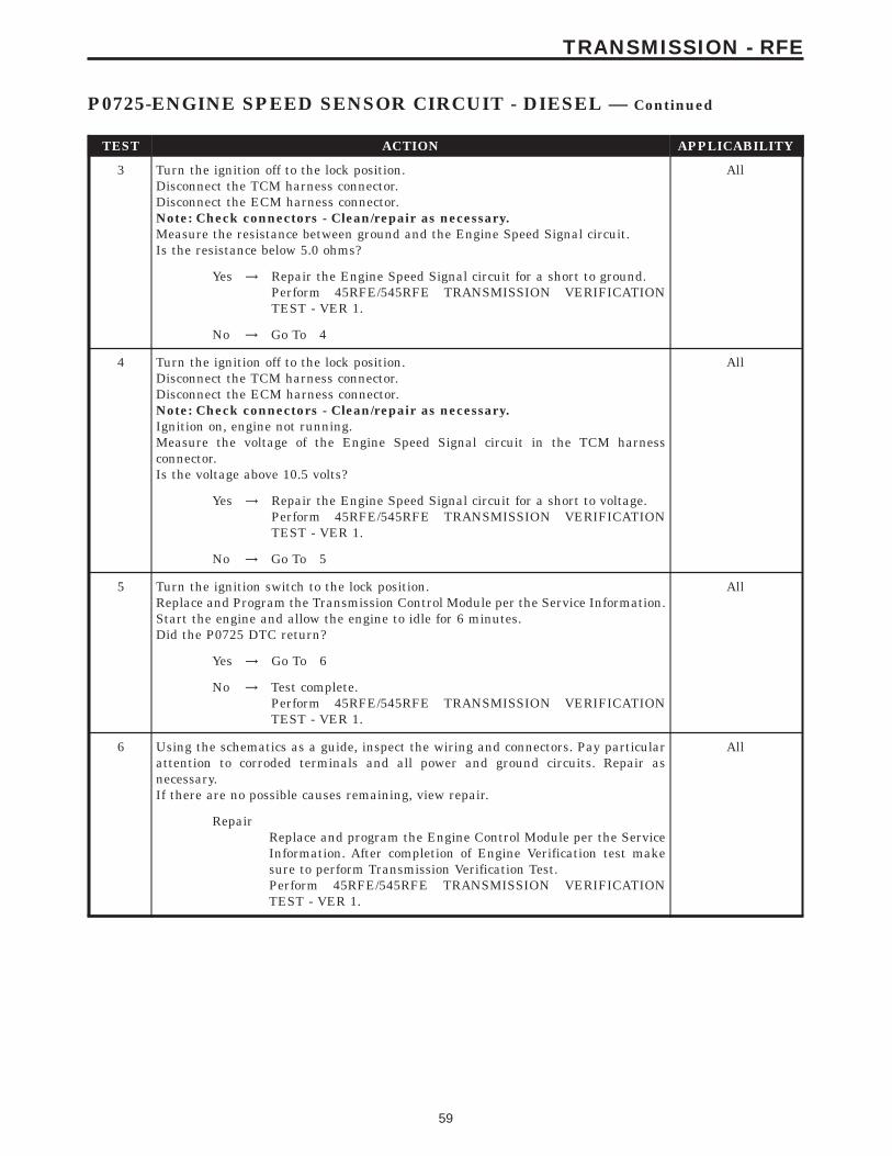
TEST ACTION APPLICABILITY
3 Turn the ignition off to the lock position.Disconnect the TCM harness connector.Disconnect the ECM harness connector.Note: Check connectors - Clean/repair as necessary.Measure the resistance between ground and the Engine Speed Signal circuit.Is the resistance below 5.0 ohms?
All
Yes → Repair the Engine Speed Signal circuit for a short to ground.Perform 45RFE/545RFE TRANSMISSION VERIFICATIONTEST - VER 1.
No → Go To 4
4 Turn the ignition off to the lock position.Disconnect the TCM harness connector.Disconnect the ECM harness connector.Note: Check connectors - Clean/repair as necessary.Ignition on, engine not running.Measure the voltage of the Engine Speed Signal circuit in the TCM harnessconnector.Is the voltage above 10.5 volts?
All
Yes → Repair the Engine Speed Signal circuit for a short to voltage.Perform 45RFE/545RFE TRANSMISSION VERIFICATIONTEST - VER 1.
No → Go To 5
5 Turn the ignition switch to the lock position.Replace and Program the Transmission Control Module per the Service Information.Start the engine and allow the engine to idle for 6 minutes.Did the P0725 DTC return?
All
Yes → Go To 6
No → Test complete.Perform 45RFE/545RFE TRANSMISSION VERIFICATIONTEST - VER 1.
6 Using the schematics as a guide, inspect the wiring and connectors. Pay particularattention to corroded terminals and all power and ground circuits. Repair asnecessary.If there are no possible causes remaining, view repair.
All
RepairReplace and program the Engine Control Module per the ServiceInformation. After completion of Engine Verification test makesure to perform Transmission Verification Test.Perform 45RFE/545RFE TRANSMISSION VERIFICATIONTEST - VER 1.
59
TRANSMISSION - RFE
P0725-ENGINE SPEED SENSOR CIRCUIT - DIESEL — Continued

TEST ACTION APPLICABILITY
7 The conditions necessary to set this DTC are not present at this time.Using the schematics as a guide, inspect the wiring and connectors specific to thiscircuit.Wiggle the wires while checking for shorts and open circuits.With the DRBIIIt, check the EATX EVENT DATA to help identify the conditions inwhich the DTC was set.Were there any problems found?
All
Yes → Repair as necessary.Perform 45RFE/545RFE TRANSMISSION VERIFICATIONTEST - VER 1.
No → Test Complete.
60
TRANSMISSION - RFE
P0725-ENGINE SPEED SENSOR CIRCUIT - DIESEL — Continued
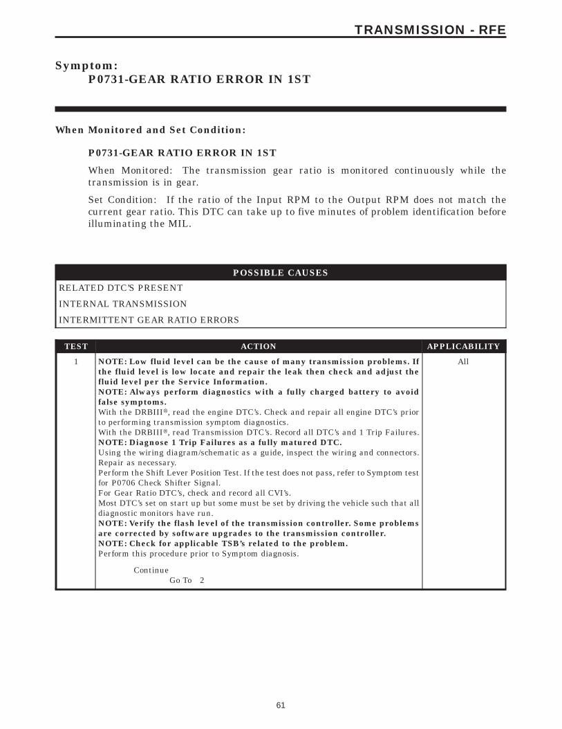
Symptom:P0731-GEAR RATIO ERROR IN 1ST
When Monitored and Set Condition:
P0731-GEAR RATIO ERROR IN 1ST
When Monitored: The transmission gear ratio is monitored continuously while thetransmission is in gear.
Set Condition: If the ratio of the Input RPM to the Output RPM does not match thecurrent gear ratio. This DTC can take up to five minutes of problem identification beforeilluminating the MIL.
POSSIBLE CAUSES
RELATED DTC’S PRESENT
INTERNAL TRANSMISSION
INTERMITTENT GEAR RATIO ERRORS
TEST ACTION APPLICABILITY
1 NOTE: Low fluid level can be the cause of many transmission problems. Ifthe fluid level is low locate and repair the leak then check and adjust thefluid level per the Service Information.NOTE: Always perform diagnostics with a fully charged battery to avoidfalse symptoms.With the DRBIIIt, read the engine DTC’s. Check and repair all engine DTC’s priorto performing transmission symptom diagnostics.With the DRBIIIt, read Transmission DTC’s. Record all DTC’s and 1 Trip Failures.NOTE: Diagnose 1 Trip Failures as a fully matured DTC.Using the wiring diagram/schematic as a guide, inspect the wiring and connectors.Repair as necessary.Perform the Shift Lever Position Test. If the test does not pass, refer to Symptom testfor P0706 Check Shifter Signal.For Gear Ratio DTC’s, check and record all CVI’s.Most DTC’s set on start up but some must be set by driving the vehicle such that alldiagnostic monitors have run.NOTE: Verify the flash level of the transmission controller. Some problemsare corrected by software upgrades to the transmission controller.NOTE: Check for applicable TSB’s related to the problem.Perform this procedure prior to Symptom diagnosis.
All
ContinueGo To 2
61
TRANSMISSION - RFE
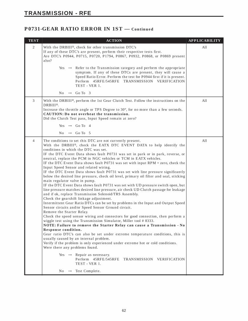
TEST ACTION APPLICABILITY
2 With the DRBIIIt, check for other transmission DTC’sIf any of these DTC’s are present, perform their respective tests first.Are DTC’s P0944, P0715, P0720, P1794, P0867, P0932, P0868, or P0869 presentalso?
All
Yes → Refer to the Transmission category and perform the appropriatesymptom. If any of these DTCs are present, they will cause aSpeed Ratio Error. Perform the test for P0944 first if it is present.Perform 45RFE/545RFE TRANSMISSION VERIFICATIONTEST - VER 1.
No → Go To 3
3 With the DRBIIIt, perform the 1st Gear Clutch Test. Follow the instructions on theDRBIIIt.Increase the throttle angle or TPS Degree to 30°, for no more than a few seconds.CAUTION: Do not overheat the transmission.Did the Clutch Test pass, Input Speed remain at zero?
All
Yes → Go To 4
No → Go To 5
4 The conditions to set this DTC are not currently present.With the DRBIIIt, check the EATX DTC EVENT DATA to help identify theconditions in which the DTC was set.IF the DTC Event Data shows fault P0731 was set in park or in park, reverse, orneutral, replace the PCM in NGC vehicles or TCM in EATX vehicles.IF the DTC Event Data shows fault P0731 was set with input RPM = zero, check theInput Speed Sensor and related wiring.IF the DTC Event Data shows fault P0731 was set with line pressure significantlybelow the desired line pressure, check oil level, primary oil filter and seal, stickingmain regulator valve in pump.IF the DTC Event Data shows fault P0731 was set with UD pressure switch open, butline pressure matches desired line pressure, air check UD Clutch passage for leakageand if ok, replace Transmission Solenoid/TRS Assembly.Check the gearshift linkage adjustment.Intermittent Gear Ratio DTCs can be set by problems in the Input and Output SpeedSensor circuits and/or Speed Sensor Ground circuit.Remove the Starter Relay.Check the speed sensor wiring and connectors for good connection, then perform awiggle test using the Transmission Simulator, Miller tool # 8333.NOTE: Failure to remove the Starter Relay can cause a Transmission - NoResponse condition.Gear ratio DTC’s can also be set under extreme temperature conditions, this isusually caused by an internal problem.Verify if the problem is only experienced under extreme hot or cold conditions.Were there any problems found.
All
Yes → Repair as necessary.Perform 45RFE/545RFE TRANSMISSION VERIFICATIONTEST - VER 1.
No → Test Complete.
62
TRANSMISSION - RFE
P0731-GEAR RATIO ERROR IN 1ST — Continued

TEST ACTION APPLICABILITY
5 Repair the transmission as necessary. If there were any line pressure DTC’s presentalong with this DTC, make sure to inspect the Transmission Oil Pump and PressureControl Solenoid per the Service Information.If the DTC’s P0876 and/or P0875 are also present, replace the TransmissionSolenoid/TRS Assembly in addition to necessary internal repairs.If there are no possible causes remaining, view repair.
All
RepairRepair internal transmission per the Service Information. In-spect, cut UD piston seal, failed overrunning clutch, cut UDaccumulator seal ring, broken UD accumulator piston, brokenreaction shaft support seal ring or dribbler orifice, bleed orifice.Perform 45RFE/545RFE TRANSMISSION VERIFICATIONTEST - VER 1.
63
TRANSMISSION - RFE
P0731-GEAR RATIO ERROR IN 1ST — Continued
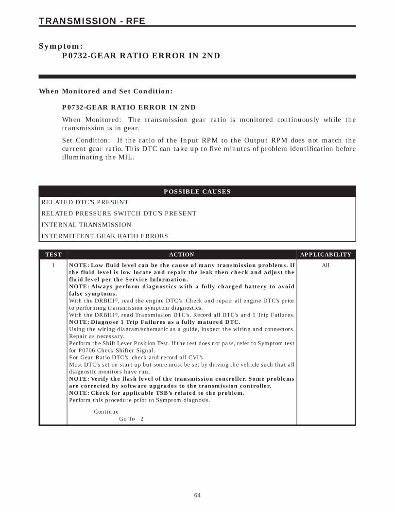
Symptom:P0732-GEAR RATIO ERROR IN 2ND
When Monitored and Set Condition:
P0732-GEAR RATIO ERROR IN 2ND
When Monitored: The transmission gear ratio is monitored continuously while thetransmission is in gear.
Set Condition: If the ratio of the Input RPM to the Output RPM does not match thecurrent gear ratio. This DTC can take up to five minutes of problem identification beforeilluminating the MIL.
POSSIBLE CAUSES
RELATED DTC’S PRESENT
RELATED PRESSURE SWITCH DTC’S PRESENT
INTERNAL TRANSMISSION
INTERMITTENT GEAR RATIO ERRORS
TEST ACTION APPLICABILITY
1 NOTE: Low fluid level can be the cause of many transmission problems. Ifthe fluid level is low locate and repair the leak then check and adjust thefluid level per the Service Information.NOTE: Always perform diagnostics with a fully charged battery to avoidfalse symptoms.With the DRBIIIt, read the engine DTC’s. Check and repair all engine DTC’s priorto performing transmission symptom diagnostics.With the DRBIIIt, read Transmission DTC’s. Record all DTC’s and 1 Trip Failures.NOTE: Diagnose 1 Trip Failures as a fully matured DTC.Using the wiring diagram/schematic as a guide, inspect the wiring and connectors.Repair as necessary.Perform the Shift Lever Position Test. If the test does not pass, refer to Symptom testfor P0706 Check Shifter Signal.For Gear Ratio DTC’s, check and record all CVI’s.Most DTC’s set on start up but some must be set by driving the vehicle such that alldiagnostic monitors have run.NOTE: Verify the flash level of the transmission controller. Some problemsare corrected by software upgrades to the transmission controller.NOTE: Check for applicable TSB’s related to the problem.Perform this procedure prior to Symptom diagnosis.
All
ContinueGo To 2
64
TRANSMISSION - RFE
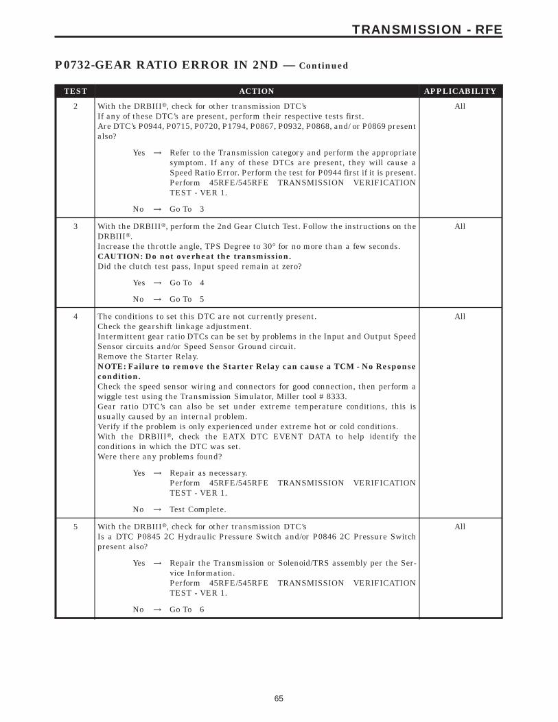
TEST ACTION APPLICABILITY
2 With the DRBIIIt, check for other transmission DTC’sIf any of these DTC’s are present, perform their respective tests first.Are DTC’s P0944, P0715, P0720, P1794, P0867, P0932, P0868, and/ or P0869 presentalso?
All
Yes → Refer to the Transmission category and perform the appropriatesymptom. If any of these DTCs are present, they will cause aSpeed Ratio Error. Perform the test for P0944 first if it is present.Perform 45RFE/545RFE TRANSMISSION VERIFICATIONTEST - VER 1.
No → Go To 3
3 With the DRBIIIt, perform the 2nd Gear Clutch Test. Follow the instructions on theDRBIIIt.Increase the throttle angle, TPS Degree to 30° for no more than a few seconds.CAUTION: Do not overheat the transmission.Did the clutch test pass, Input speed remain at zero?
All
Yes → Go To 4
No → Go To 5
4 The conditions to set this DTC are not currently present.Check the gearshift linkage adjustment.Intermittent gear ratio DTCs can be set by problems in the Input and Output SpeedSensor circuits and/or Speed Sensor Ground circuit.Remove the Starter Relay.NOTE: Failure to remove the Starter Relay can cause a TCM - No Responsecondition.Check the speed sensor wiring and connectors for good connection, then perform awiggle test using the Transmission Simulator, Miller tool # 8333.Gear ratio DTC’s can also be set under extreme temperature conditions, this isusually caused by an internal problem.Verify if the problem is only experienced under extreme hot or cold conditions.With the DRBIIIt, check the EATX DTC EVENT DATA to help identify theconditions in which the DTC was set.Were there any problems found?
All
Yes → Repair as necessary.Perform 45RFE/545RFE TRANSMISSION VERIFICATIONTEST - VER 1.
No → Test Complete.
5 With the DRBIIIt, check for other transmission DTC’sIs a DTC P0845 2C Hydraulic Pressure Switch and/or P0846 2C Pressure Switchpresent also?
All
Yes → Repair the Transmission or Solenoid/TRS assembly per the Ser-vice Information.Perform 45RFE/545RFE TRANSMISSION VERIFICATIONTEST - VER 1.
No → Go To 6
65
TRANSMISSION - RFE
P0732-GEAR RATIO ERROR IN 2ND — Continued

TEST ACTION APPLICABILITY
6 Repair internal transmission as necessary. If any line pressure DTCs are presentalong with this DTC, make sure to inspect the Transmission Oil Pump and PressureControl Solenoid per the Service Information.If DTC’s P0846 and/or P0845 are also present, replace the Transmission Solenoid/TRS Assembly in addition to internal repairs.If there are no possible causes remaining, view repair.
All
RepairRepair internal transmission per the Service Information.Perform 45RFE/545RFE TRANSMISSION VERIFICATIONTEST - VER 1.
66
TRANSMISSION - RFE
P0732-GEAR RATIO ERROR IN 2ND — Continued

Symptom:P0733-GEAR RATIO ERROR IN 3RD
When Monitored and Set Condition:
P0733-GEAR RATIO ERROR IN 3RD
When Monitored: The transmission gear ratio is monitored continuously while thetransmission is in gear.
Set Condition: If the ratio of the Input RPM to the Output RPM does not match thecurrent gear ratio. This DTC can take up to five minutes of problem identification beforeilluminating the MIL.
POSSIBLE CAUSES
PRESSURE SWITCH DTC’S PRESENT
RELATED DTC’S PRESENT
INTERNAL TRANSMISSION
INTERMITTENT GEAR RATIO ERRORS
TEST ACTION APPLICABILITY
1 NOTE: Low fluid level can be the cause of many transmission problems. Ifthe fluid level is low locate and repair the leak then check and adjust thefluid level per the Service Information.NOTE: Always perform diagnostics with a fully charged battery to avoidfalse symptoms.With the DRBIIIt, read the engine DTC’s. Check and repair all engine DTC’s priorto performing transmission symptom diagnostics.With the DRBIIIt, read Transmission DTC’s. Record all DTC’s and 1 Trip Failures.NOTE: Diagnose 1 Trip Failures as a fully matured DTC.Using the wiring diagram/schematic as a guide, inspect the wiring and connectors.Repair as necessary.Perform the Shift Lever Position Test. If the test does not pass, refer to Symptom testfor P0706 Check Shifter Signal.For Gear Ratio DTC’s, check and record all CVI’s.Most DTC’s set on start up but some must be set by driving the vehicle such that alldiagnostic monitors have run.NOTE: Verify the flash level of the transmission controller. Some problemsare corrected by software upgrades to the transmission controller.NOTE: Check for applicable TSB’s related to the problem.Perform this procedure prior to Symptom diagnosis.
All
ContinueGo To 2
67
TRANSMISSION - RFE
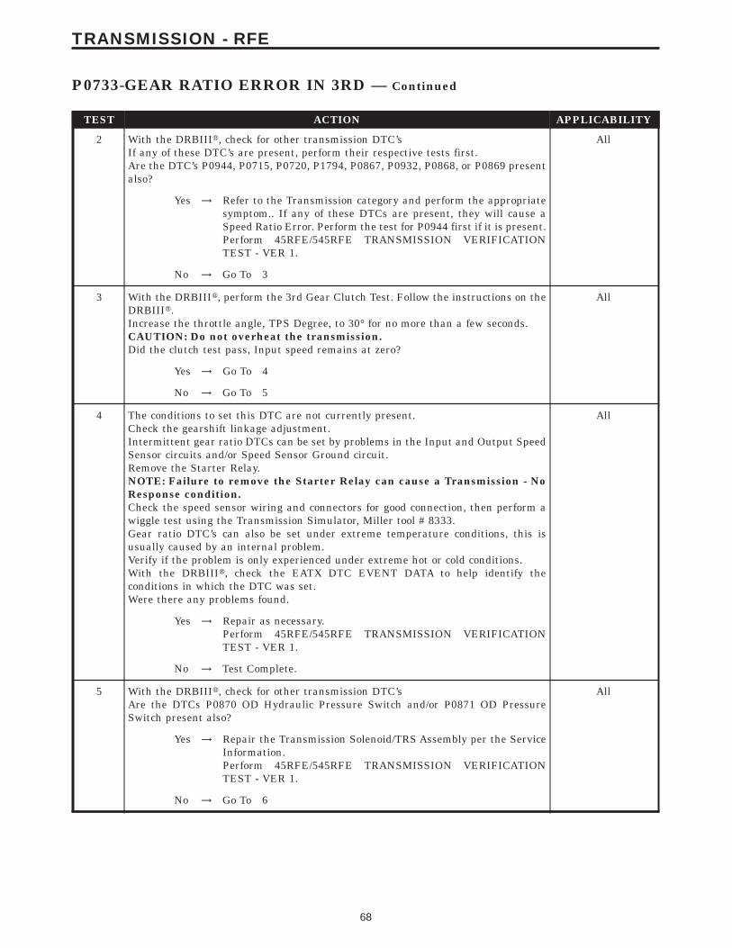
TEST ACTION APPLICABILITY
2 With the DRBIIIt, check for other transmission DTC’sIf any of these DTC’s are present, perform their respective tests first.Are the DTC’s P0944, P0715, P0720, P1794, P0867, P0932, P0868, or P0869 presentalso?
All
Yes → Refer to the Transmission category and perform the appropriatesymptom.. If any of these DTCs are present, they will cause aSpeed Ratio Error. Perform the test for P0944 first if it is present.Perform 45RFE/545RFE TRANSMISSION VERIFICATIONTEST - VER 1.
No → Go To 3
3 With the DRBIIIt, perform the 3rd Gear Clutch Test. Follow the instructions on theDRBIIIt.Increase the throttle angle, TPS Degree, to 30° for no more than a few seconds.CAUTION: Do not overheat the transmission.Did the clutch test pass, Input speed remains at zero?
All
Yes → Go To 4
No → Go To 5
4 The conditions to set this DTC are not currently present.Check the gearshift linkage adjustment.Intermittent gear ratio DTCs can be set by problems in the Input and Output SpeedSensor circuits and/or Speed Sensor Ground circuit.Remove the Starter Relay.NOTE: Failure to remove the Starter Relay can cause a Transmission - NoResponse condition.Check the speed sensor wiring and connectors for good connection, then perform awiggle test using the Transmission Simulator, Miller tool # 8333.Gear ratio DTC’s can also be set under extreme temperature conditions, this isusually caused by an internal problem.Verify if the problem is only experienced under extreme hot or cold conditions.With the DRBIIIt, check the EATX DTC EVENT DATA to help identify theconditions in which the DTC was set.Were there any problems found.
All
Yes → Repair as necessary.Perform 45RFE/545RFE TRANSMISSION VERIFICATIONTEST - VER 1.
No → Test Complete.
5 With the DRBIIIt, check for other transmission DTC’sAre the DTCs P0870 OD Hydraulic Pressure Switch and/or P0871 OD PressureSwitch present also?
All
Yes → Repair the Transmission Solenoid/TRS Assembly per the ServiceInformation.Perform 45RFE/545RFE TRANSMISSION VERIFICATIONTEST - VER 1.
No → Go To 6
68
TRANSMISSION - RFE
P0733-GEAR RATIO ERROR IN 3RD — Continued

TEST ACTION APPLICABILITY
6 Repair or replace the transmission as necessary.If the transmission is to be repaired, and there were any line pressure DTC’s presentalong with this DTC, make sure to inspect the Transmission Oil Pump and PressureControl Solenoid per the Service Information.NOTE: If DTC’s P0871 and/or P0870 are also present, replace the TransmissionSolenoid/TRS Assembly in addition to necessary internal repairs.If there are no possible causes remaining, view repair.
All
RepairRepair internal transmission problem per the Service Informa-tion.Perform 45RFE/545RFE TRANSMISSION VERIFICATIONTEST - VER 1.
69
TRANSMISSION - RFE
P0733-GEAR RATIO ERROR IN 3RD — Continued

Symptom:P0734-GEAR RATIO ERROR IN 4TH
When Monitored and Set Condition:
P0734-GEAR RATIO ERROR IN 4TH
When Monitored: The transmission gear ratio is monitored continuously while thetransmission is in gear.
Set Condition: If the ratio of the Input RPM to the Output RPM does not match thecurrent gear ratio. This DTC can take up to five minutes of problem identification beforeilluminating the MIL.
POSSIBLE CAUSES
RELATED DTC’S PRESENT
RELATED PRESSURE SWITCH DTC’S PRESENT
INTERNAL TRANSMISSION
TEST ACTION APPLICABILITY
1 NOTE: Low fluid level can be the cause of many transmission problems. Ifthe fluid level is low locate and repair the leak then check and adjust thefluid level per the Service Information.NOTE: Always perform diagnostics with a fully charged battery to avoidfalse symptoms.With the DRBIIIt, read the engine DTC’s. Check and repair all engine DTC’s priorto performing transmission symptom diagnostics.With the DRBIIIt, read Transmission DTC’s. Record all DTC’s and 1 Trip Failures.NOTE: Diagnose 1 Trip Failures as a fully matured DTC.Using the wiring diagram/schematic as a guide, inspect the wiring and connectors.Repair as necessary.Perform the Shift Lever Position Test. If the test does not pass, refer to Symptom testfor P0706 Check Shifter Signal.For Gear Ratio DTC’s, check and record all CVI’s.Most DTC’s set on start up but some must be set by driving the vehicle such that alldiagnostic monitors have run.NOTE: Verify the flash level of the transmission controller. Some problemsare corrected by software upgrades to the transmission controller.NOTE: Check for applicable TSB’s related to the problem.Perform this procedure prior to Symptom diagnosis.
All
ContinueGo To 2
70
TRANSMISSION - RFE
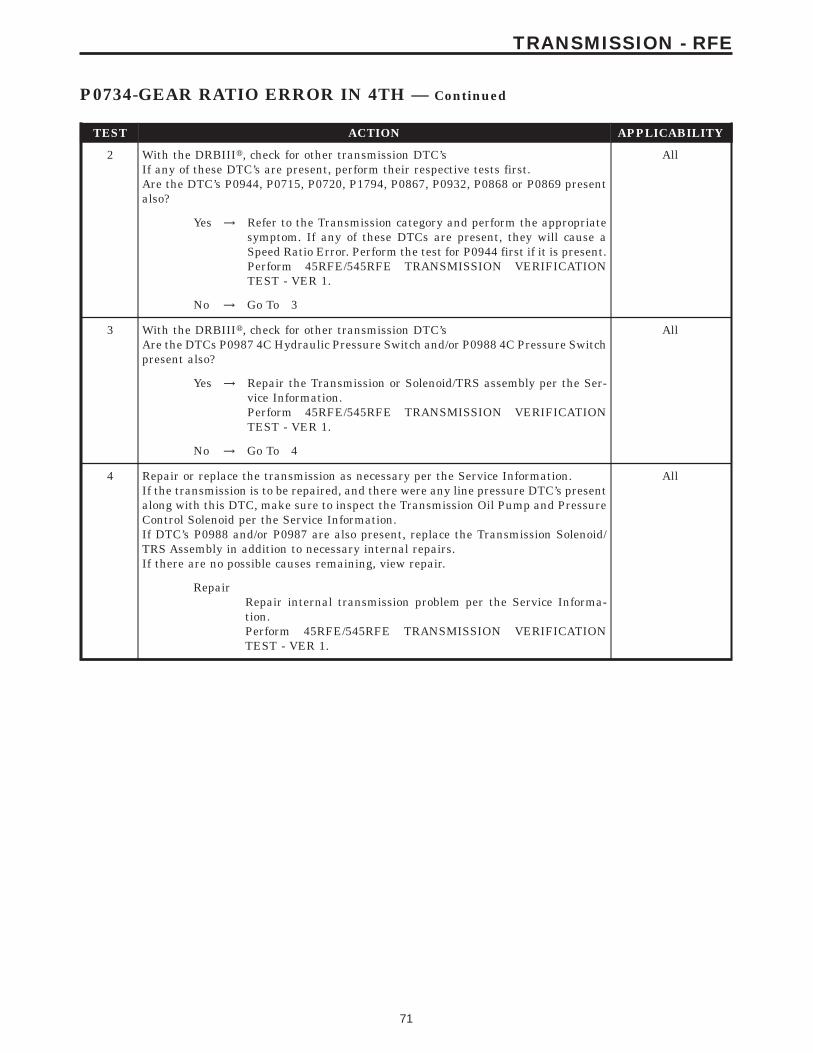
TEST ACTION APPLICABILITY
2 With the DRBIIIt, check for other transmission DTC’sIf any of these DTC’s are present, perform their respective tests first.Are the DTC’s P0944, P0715, P0720, P1794, P0867, P0932, P0868 or P0869 presentalso?
All
Yes → Refer to the Transmission category and perform the appropriatesymptom. If any of these DTCs are present, they will cause aSpeed Ratio Error. Perform the test for P0944 first if it is present.Perform 45RFE/545RFE TRANSMISSION VERIFICATIONTEST - VER 1.
No → Go To 3
3 With the DRBIIIt, check for other transmission DTC’sAre the DTCs P0987 4C Hydraulic Pressure Switch and/or P0988 4C Pressure Switchpresent also?
All
Yes → Repair the Transmission or Solenoid/TRS assembly per the Ser-vice Information.Perform 45RFE/545RFE TRANSMISSION VERIFICATIONTEST - VER 1.
No → Go To 4
4 Repair or replace the transmission as necessary per the Service Information.If the transmission is to be repaired, and there were any line pressure DTC’s presentalong with this DTC, make sure to inspect the Transmission Oil Pump and PressureControl Solenoid per the Service Information.If DTC’s P0988 and/or P0987 are also present, replace the Transmission Solenoid/TRS Assembly in addition to necessary internal repairs.If there are no possible causes remaining, view repair.
All
RepairRepair internal transmission problem per the Service Informa-tion.Perform 45RFE/545RFE TRANSMISSION VERIFICATIONTEST - VER 1.
71
TRANSMISSION - RFE
P0734-GEAR RATIO ERROR IN 4TH — Continued
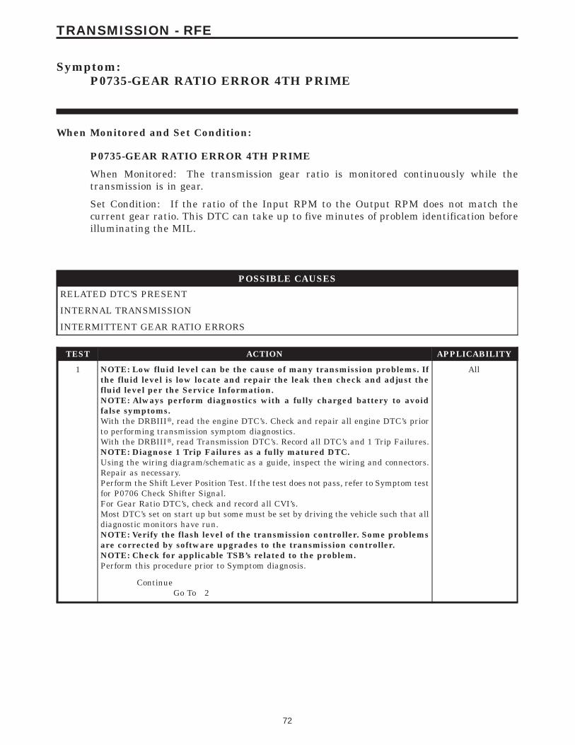
Symptom:P0735-GEAR RATIO ERROR 4TH PRIME
When Monitored and Set Condition:
P0735-GEAR RATIO ERROR 4TH PRIME
When Monitored: The transmission gear ratio is monitored continuously while thetransmission is in gear.
Set Condition: If the ratio of the Input RPM to the Output RPM does not match thecurrent gear ratio. This DTC can take up to five minutes of problem identification beforeilluminating the MIL.
POSSIBLE CAUSES
RELATED DTC’S PRESENT
INTERNAL TRANSMISSION
INTERMITTENT GEAR RATIO ERRORS
TEST ACTION APPLICABILITY
1 NOTE: Low fluid level can be the cause of many transmission problems. Ifthe fluid level is low locate and repair the leak then check and adjust thefluid level per the Service Information.NOTE: Always perform diagnostics with a fully charged battery to avoidfalse symptoms.With the DRBIIIt, read the engine DTC’s. Check and repair all engine DTC’s priorto performing transmission symptom diagnostics.With the DRBIIIt, read Transmission DTC’s. Record all DTC’s and 1 Trip Failures.NOTE: Diagnose 1 Trip Failures as a fully matured DTC.Using the wiring diagram/schematic as a guide, inspect the wiring and connectors.Repair as necessary.Perform the Shift Lever Position Test. If the test does not pass, refer to Symptom testfor P0706 Check Shifter Signal.For Gear Ratio DTC’s, check and record all CVI’s.Most DTC’s set on start up but some must be set by driving the vehicle such that alldiagnostic monitors have run.NOTE: Verify the flash level of the transmission controller. Some problemsare corrected by software upgrades to the transmission controller.NOTE: Check for applicable TSB’s related to the problem.Perform this procedure prior to Symptom diagnosis.
All
ContinueGo To 2
72
TRANSMISSION - RFE
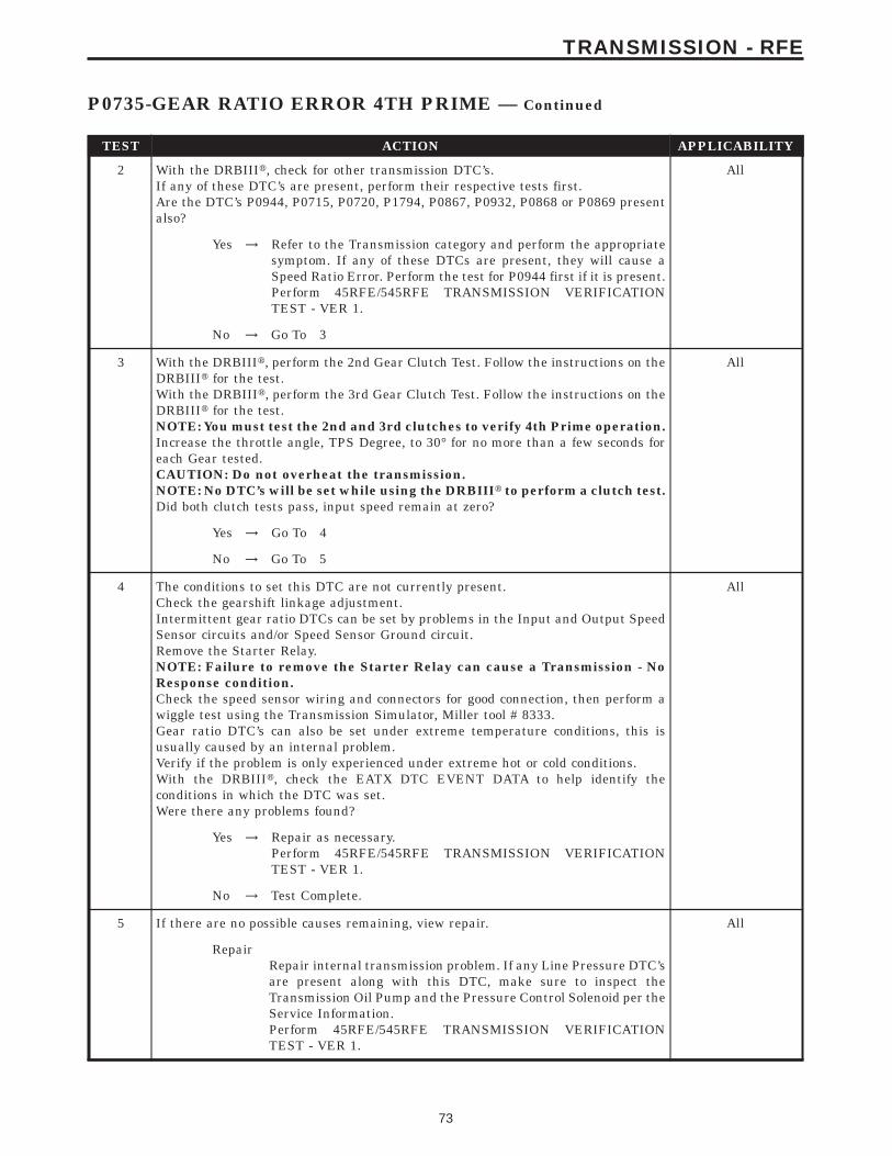
TEST ACTION APPLICABILITY
2 With the DRBIIIt, check for other transmission DTC’s.If any of these DTC’s are present, perform their respective tests first.Are the DTC’s P0944, P0715, P0720, P1794, P0867, P0932, P0868 or P0869 presentalso?
All
Yes → Refer to the Transmission category and perform the appropriatesymptom. If any of these DTCs are present, they will cause aSpeed Ratio Error. Perform the test for P0944 first if it is present.Perform 45RFE/545RFE TRANSMISSION VERIFICATIONTEST - VER 1.
No → Go To 3
3 With the DRBIIIt, perform the 2nd Gear Clutch Test. Follow the instructions on theDRBIIIt for the test.With the DRBIIIt, perform the 3rd Gear Clutch Test. Follow the instructions on theDRBIIIt for the test.NOTE: You must test the 2nd and 3rd clutches to verify 4th Prime operation.Increase the throttle angle, TPS Degree, to 30° for no more than a few seconds foreach Gear tested.CAUTION: Do not overheat the transmission.NOTE: No DTC’s will be set while using the DRBIIIt to perform a clutch test.Did both clutch tests pass, input speed remain at zero?
All
Yes → Go To 4
No → Go To 5
4 The conditions to set this DTC are not currently present.Check the gearshift linkage adjustment.Intermittent gear ratio DTCs can be set by problems in the Input and Output SpeedSensor circuits and/or Speed Sensor Ground circuit.Remove the Starter Relay.NOTE: Failure to remove the Starter Relay can cause a Transmission - NoResponse condition.Check the speed sensor wiring and connectors for good connection, then perform awiggle test using the Transmission Simulator, Miller tool # 8333.Gear ratio DTC’s can also be set under extreme temperature conditions, this isusually caused by an internal problem.Verify if the problem is only experienced under extreme hot or cold conditions.With the DRBIIIt, check the EATX DTC EVENT DATA to help identify theconditions in which the DTC was set.Were there any problems found?
All
Yes → Repair as necessary.Perform 45RFE/545RFE TRANSMISSION VERIFICATIONTEST - VER 1.
No → Test Complete.
5 If there are no possible causes remaining, view repair. All
RepairRepair internal transmission problem. If any Line Pressure DTC’sare present along with this DTC, make sure to inspect theTransmission Oil Pump and the Pressure Control Solenoid per theService Information.Perform 45RFE/545RFE TRANSMISSION VERIFICATIONTEST - VER 1.
73
TRANSMISSION - RFE
P0735-GEAR RATIO ERROR 4TH PRIME — Continued

Symptom:P0736-GEAR RATIO ERROR IN REVERSE
When Monitored and Set Condition:
P0736-GEAR RATIO ERROR IN REVERSE
When Monitored: The transmission gear ratio is monitored continuously while thetransmission is in gear.
Set Condition: If the ratio of the Input RPM to the Output RPM does not match thecurrent gear ratio. This DTC can take up to five minutes of problem identification beforeilluminating the MIL.
POSSIBLE CAUSES
RELATED DTC’S PRESENT
INTERNAL TRANSMISSION
INTERMITTENT GEAR RATIO ERRORS
TEST ACTION APPLICABILITY
1 NOTE: Low fluid level can be the cause of many transmission problems. Ifthe fluid level is low locate and repair the leak then check and adjust thefluid level per the Service Information.NOTE: Always perform diagnostics with a fully charged battery to avoidfalse symptoms.With the DRBIIIt, read the engine DTC’s. Check and repair all engine DTC’s priorto performing transmission symptom diagnostics.With the DRBIIIt, read Transmission DTC’s. Record all DTC’s and 1 Trip Failures.NOTE: Diagnose 1 Trip Failures as a fully matured DTC.Using the wiring diagram/schematic as a guide, inspect the wiring and connectors.Repair as necessary.Perform the Shift Lever Position Test. If the test does not pass, refer to Symptom testfor P0706 Check Shifter Signal.For Gear Ratio DTC’s, check and record all CVI’s.Most DTC’s set on start up but some must be set by driving the vehicle such that alldiagnostic monitors have run.NOTE: Verify the flash level of the transmission controller. Some problemsare corrected by software upgrades to the transmission controller.NOTE: Check for applicable TSB’s related to the problem.Perform this procedure prior to Symptom diagnosis.
All
ContinueGo To 2
74
TRANSMISSION - RFE

TEST ACTION APPLICABILITY
2 With the DRBIIIt, check for other transmission DTC’s.If any of these DTC’s are present, perform their respective tests first.Are the DTC’s P0944, P0715, P0720, P1794, P0867, P0932, P0868 or P0869 presentalso?
All
Yes → Refer to the Transmission category and perform the appropriatesymptom. If any of these DTCs are present, they will cause aSpeed Ratio Error. Perform the test for P0944 first if it is present.Perform 45RFE/545RFE TRANSMISSION VERIFICATIONTEST - VER 1.
No → Go To 3
3 With the DRBIIIt, perform the Reverse Gear Clutch Test. Follow the instructions onthe DRBIIIt.Increase the throttle angle , TPS Degree, to 30°, for no more than a few seconds.CAUTION: Do not overheat the transmission.Did the clutch test pass, Input speed remain at zero?
All
Yes → Go To 4
No → Go To 5
4 The conditions to set this DTC are not currently present.Check the shifter adjustment.Intermittent gear ratio DTCs can be set by problems in the Input and Output SpeedSensor circuits and/or Speed Sensor Ground circuit.Remove the Starter Relay.NOTE: Failure to remove the Starter Relay can cause a TCM - No Responsecondition.Check the speed sensor wiring and connectors for good connection, then perform awiggle test using the Transmission Simulator, Miller tool # 8333.Gear ratio DTC’s can also be set under extreme temperature conditions, this isusually caused by an internal problem.Verify if the problem is only experienced under extreme hot or cold conditionsWith the DRBIIIt, check the EATX DTC EVENT DATA to help identify theconditions in which the DTC was set.Were there any problems found?
All
Yes → Repair as necessary.Perform 45RFE/545RFE TRANSMISSION VERIFICATIONTEST - VER 1.
No → Test Complete.
5 If there are no possible causes remaining, view repair. All
RepairRepair internal transmission problem. If there are any LinePressure DTC’s present along with this DTC, make sure to inspectthe Transmission Oil Pump and Pressure Control Solenoid per theService Information.Perform 45RFE/545RFE TRANSMISSION VERIFICATIONTEST - VER 1.
75
TRANSMISSION - RFE
P0736-GEAR RATIO ERROR IN REVERSE — Continued

Symptom:P0740-TCC OUT OF RANGE
When Monitored and Set Condition:
P0740-TCC OUT OF RANGE
When Monitored: During Electronically Modulated Converter Clutch (EMCC) Operation.
Set Condition: Transmission must be in EMCC, with input speed > than 1750 RPM.TCC-L/R Solenoid achieves the maximum duty cycle and can not pull engine speed within60 RPM of input speed. Also when the transmission is in FEMCC and the engine slips TCC> than 100 RPM for 10 seconds. This DTC can take up to five minutes of problemidentification before illuminating the MIL.
POSSIBLE CAUSES
RELATED DTC P0750 PRESENT
INTERNAL TRANSMISSION
TRANSMISSION SOLENOID/TRS ASSEMBLY
INTERMITTENT WIRING AND CONNECTORS
TEST ACTION APPLICABILITY
1 NOTE: Low fluid level can be the cause of many transmission problems. Ifthe fluid level is low locate and repair the leak then check and adjust thefluid level per the Service Information.NOTE: Always perform diagnostics with a fully charged battery to avoidfalse symptoms.With the DRBIIIt, read the engine DTC’s. Check and repair all engine DTC’s priorto performing transmission symptom diagnostics.With the DRBIIIt, read Transmission DTC’s. Record all DTC’s and 1 Trip Failures.NOTE: Diagnose 1 Trip Failures as a fully matured DTC.Using the wiring diagram/schematic as a guide, inspect the wiring and connectors.Repair as necessary.Perform the Shift Lever Position Test. If the test does not pass, refer to Symptom testfor P0706 Check Shifter Signal.For Gear Ratio DTC’s, check and record all CVI’s.Most DTC’s set on start up but some must be set by driving the vehicle such that alldiagnostic monitors have run.NOTE: Verify the flash level of the transmission controller. Some problemsare corrected by software upgrades to the transmission controller.NOTE: Check for applicable TSB’s related to the problem.Perform this procedure prior to Symptom diagnosis.
All
ContinueGo To 2
76
TRANSMISSION - RFE

TEST ACTION APPLICABILITY
2 With the DRBIIIt, read transmission DTC’s.Is the DTC P0750 present?
All
Yes → Refer to the Transmission category and perform the appropriatesymptom.Perform 45RFE/545RFE TRANSMISSION VERIFICATIONTEST - VER 1.
No → Go To 3
3 With the DRBIIIt, Read and RECORD ALL Transmission DTC’s. After recordingDTC’s, erase DTC’s.Drive the vehicle until the transmission temperature is at least 43°C or 110°F.Perform the following steps 3 times.Drive the vehicle at 80 km/h or 50 MPH.Allow 4th gear to engage for at least 10 seconds.Close the Throttle.Tip back into the throttle until the TPS angle is between 25 and 29 degrees.NOTE: If the throttle angle goes over 30 degrees, you must close the throttleand try again.Did the TCC engage (Engine speed approximately equal to input speed) during anyof the attempts?
All
Yes → Go To 4
No → Go To 5
4 The conditions necessary to set this DTC are not present at this time.Using the schematics as a guide, inspect the wiring and connectors specific to thiscircuit.Wiggle the wires while checking for shorts and open circuits.With the DRBIIIt, check the EATX DTC EVENT DATA to help identify theconditions in which the DTC was set.Were there any problems found?
All
Yes → Repair as necessary.Perform 45RFE/545RFE TRANSMISSION VERIFICATIONTEST - VER 1.
No → Test Complete.
5 With the DRBIIIt, check for other transmission DTC’s.Are the DTCs P1775 and P0841 present also?
All
Yes → Replace the Transmission Solenoid/TRS Assembly per the ServiceInformation.Perform 45RFE/545RFE TRANSMISSION VERIFICATIONTEST - VER 1.
No → Go To 6
6 If there are no possible causes remaining, view repair. All
RepairRepair internal transmission per the Service Information. Inspectthe Primary Oil Pump and replace if necessary. If no problems arefound in the Oil Pump, replace the Transmission Solenoid/TRSAssembly. Replace the Torque Converter in either case.Perform 45RFE/545RFE TRANSMISSION VERIFICATIONTEST - VER 1.
77
TRANSMISSION - RFE
P0740-TCC OUT OF RANGE — Continued

Symptom:P0750-LR SOLENOID CIRCUIT
When Monitored and Set Condition:
P0750-LR SOLENOID CIRCUIT
When Monitored: Initially at power-up, then every 10 seconds thereafter. It will also betested immediately after a gear ratio or pressure switch error is detected.
Set Condition: After three consecutive solenoid continuity tests failures. After one failureif a test is run in response to a gear ratio or pressure switch error.
POSSIBLE CAUSES
RELATED RELAY DTC’S PRESENT
TRANSMISSION CONTROL RELAY OUTPUT CIRCUIT OPEN
LR SOLENOID CONTROL CIRCUIT OPEN
LR SOLENOID CONTROL CIRCUIT SHORT TO GROUND
LR SOLENOID CONTROL CIRCUIT SHORT TO VOLTAGE
TRANSMISSION SOLENOID/TRS ASSEMBLY
TRANSMISSION CONTROL MODULE
INTERMITTENT WIRING AND CONNECTORS
TEST ACTION APPLICABILITY
1 NOTE: Low fluid level can be the cause of many transmission problems. Ifthe fluid level is low locate and repair the leak then check and adjust thefluid level per the Service Information.NOTE: Always perform diagnostics with a fully charged battery to avoidfalse symptoms.With the DRBIIIt, read the engine DTC’s. Check and repair all engine DTC’s priorto performing transmission symptom diagnostics.With the DRBIIIt, read Transmission DTC’s. Record all DTC’s and 1 Trip Failures.NOTE: Diagnose 1 Trip Failures as a fully matured DTC.Using the wiring diagram/schematic as a guide, inspect the wiring and connectors.Repair as necessary.Perform the Shift Lever Position Test. If the test does not pass, refer to Symptom testfor P0706 Check Shifter Signal.For Gear Ratio DTC’s, check and record all CVI’s.Most DTC’s set on start up but some must be set by driving the vehicle such that alldiagnostic monitors have run.NOTE: Verify the flash level of the transmission controller. Some problemsare corrected by software upgrades to the transmission controller.NOTE: Check for applicable TSB’s related to the problem.Perform this procedure prior to Symptom diagnosis.
All
ContinueGo To 2
78
TRANSMISSION - RFE

TEST ACTION APPLICABILITY
2 With the DRBIIIt, check for other transmission DTC’s.Are there any Transmission Control Relay related DTC’s P0890, P0891, or P0888present?
All
Yes → Refer to the Transmission category and perform the appropriatesymptom.Perform 45RFE/545RFE TRANSMISSION VERIFICATIONTEST - VER 1.
No → Go To 3
3 With the DRBIIIt, check the STARTS SINCE SET counter for P0750.NOTE: This counter only applies to the last DTC set.Is the STARTS SINCE SET counter for P0750 set at 0?
All
Yes → Go To 4
No → Go To 11
4 Turn the ignition off to the lock position.Remove the Starter Relay.NOTE: Failure to remove the Starter Relay can cause a Transmission - NoResponse condition.Install the Transmission Simulator, Miller tool #8333.Note: Check connectors - Clean/repair as necessary.Ignition on, engine not running.Monitor the LR Solenoid LED on the Transmission Simulator.With the DRBIIIt, actuate the LR Solenoid.Did the LR Solenoid LED on the Transmission Simulator blink on and off?
All
Yes → Go To 5
No → Go To 6
5 If there are no possible causes remaining, view repair. All
RepairReplace the Transmission Solenoid/TRS Assembly per the ServiceInformation.Perform 45RFE/545RFE TRANSMISSION VERIFICATIONTEST - VER 1.
6 Turn the ignition off to the lock position.Disconnect the TCM harness connectorDisconnect the Transmission Solenoid /TRS Assembly harness connectorNote: Check connectors - Clean/repair as necessary.Measure the resistance of the LR Solenoid Control circuit from the TCM harnessconnector to the Transmission Solenoid/TRS Assembly harness connector.Is the resistance above 5.0 ohms?
All
Yes → Repair the LR Solenoid Control circuit for an open.Perform 45RFE/545RFE TRANSMISSION VERIFICATIONTEST - VER 1.
No → Go To 7
79
TRANSMISSION - RFE
P0750-LR SOLENOID CIRCUIT — Continued

TEST ACTION APPLICABILITY
7 Turn the ignition off to the lock position.Disconnect the TCM harness connector.Disconnect the Transmission Solenoid/TRS Assembly harness connector.Note: Check connectors - Clean/repair as necessary.Measure the resistance between ground and the LR Solenoid Control circuit.Is the resistance below 5.0 ohms?
All
Yes → Repair the LR Solenoid Control circuit for a short to ground.Perform 45RFE/545RFE TRANSMISSION VERIFICATIONTEST - VER 1.
No → Go To 8
8 Turn the ignition off to the lock position.Disconnect the TCM harness connector.Disconnect the Transmission Solenoid/TRS Assembly harness connector.Remove the Transmission Control Relay.Note: Check connectors - Clean/repair as necessary.Connect a jumper wire between the Fused B+ circuit and the Transmission ControlRelay Output circuit in the Transmission Control Relay connector.Ignition on, engine not running.Measure the voltage of the LR Solenoid Control circuit.Is the voltage above 0.5 volt?
All
Yes → Repair the LR Solenoid Control circuit for a short to voltage.Perform 45RFE/545RFE TRANSMISSION VERIFICATIONTEST - VER 1.
No → Go To 9
9 Turn the ignition off to the lock position.Disconnect the Transmission Solenoid/TRS Assembly harness connector.Remove the Transmission Control Relay.NOTE: Check connectors - Clean/repair as necessary.Connect a jumper wire between the Fused B+ circuit and the Transmission ControlRelay Output circuit in the Transmission Control Relay connector.Ignition on, engine not running.Using a 12-volt test light connected to ground, check the Transmission Control RelayOutput circuit in the Transmission Solenoid/TRS Assembly harness connector.NOTE: The test light must illuminate brightly. Compare the brightness tothat of a direct connection to the battery.Does the test light illuminate brightly?
All
Yes → Go To 10
No → Repair the Transmission Control Relay Output circuit for an openor high resistance.Perform 45RFE/545RFE TRANSMISSION VERIFICATIONTEST - VER 1.
10 Using the schematics as a guide, inspect the wiring and connectors. Repair asnecessary. Pay particular attention to all power and ground circuits.If there are no possible causes remaining, view repair.
All
RepairReplace the Transmission Control Module per the Service Infor-mation. WITH THE DRBIIIt PERFORM QUICK LEARN.Perform 45RFE/545RFE TRANSMISSION VERIFICATIONTEST - VER 1.
80
TRANSMISSION - RFE
P0750-LR SOLENOID CIRCUIT — Continued
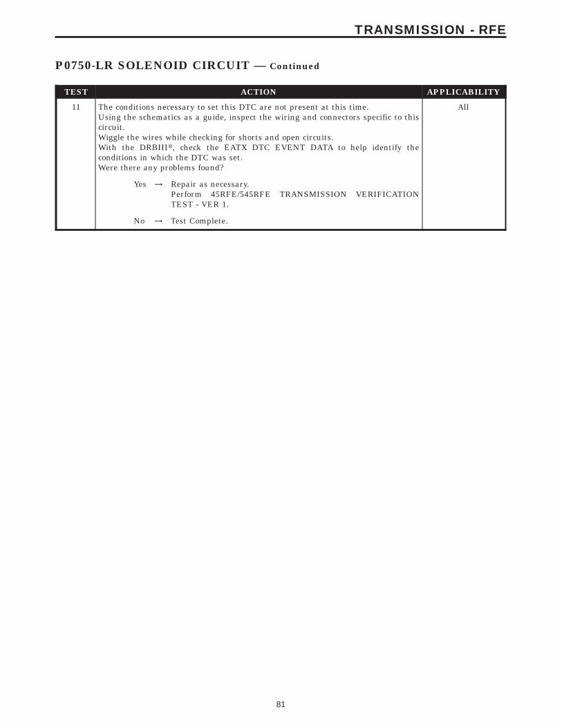
TEST ACTION APPLICABILITY
11 The conditions necessary to set this DTC are not present at this time.Using the schematics as a guide, inspect the wiring and connectors specific to thiscircuit.Wiggle the wires while checking for shorts and open circuits.With the DRBIIIt, check the EATX DTC EVENT DATA to help identify theconditions in which the DTC was set.Were there any problems found?
All
Yes → Repair as necessary.Perform 45RFE/545RFE TRANSMISSION VERIFICATIONTEST - VER 1.
No → Test Complete.
81
TRANSMISSION - RFE
P0750-LR SOLENOID CIRCUIT — Continued

Symptom:P0755-2C SOLENOID CIRCUIT
When Monitored and Set Condition:
P0755-2C SOLENOID CIRCUIT
When Monitored: Initially at power-up, then every 10 seconds thereafter. It will also betested immediately after a gear ratio or pressure switch error is detected.
Set Condition: After three consecutive solenoid continuity tests failures. After one failureif a test is run in response to a gear ratio or pressure switch error.
POSSIBLE CAUSES
RELATED RELAY DTC’S PRESENT
TRANSMISSION CONTROL RELAY OUTPUT CIRCUIT OPEN
2C SOLENOID CONTROL CIRCUIT OPEN
2C SOLENOID CONTROL CIRCUIT SHORT TO GROUND
2C SOLENOID CONTROL CIRCUIT SHORT TO VOLTAGE
TRANSMISSION SOLENOID/TRS ASSEMBLY
TRANSMISSION CONTROL MODULE
INTERMITTENT WIRING AND CONNECTORS
TEST ACTION APPLICABILITY
1 NOTE: Low fluid level can be the cause of many transmission problems. Ifthe fluid level is low locate and repair the leak then check and adjust thefluid level per the Service Information.NOTE: Always perform diagnostics with a fully charged battery to avoidfalse symptoms.With the DRBIIIt, read the engine DTC’s. Check and repair all engine DTC’s priorto performing transmission symptom diagnostics.With the DRBIIIt, read Transmission DTC’s. Record all DTC’s and 1 Trip Failures.NOTE: Diagnose 1 Trip Failures as a fully matured DTC.Using the wiring diagram/schematic as a guide, inspect the wiring and connectors.Repair as necessary.Perform the Shift Lever Position Test. If the test does not pass, refer to Symptom testfor P0706 Check Shifter Signal.For Gear Ratio DTC’s, check and record all CVI’s.Most DTC’s set on start up but some must be set by driving the vehicle such that alldiagnostic monitors have run.NOTE: Verify the flash level of the transmission controller. Some problemsare corrected by software upgrades to the transmission controller.NOTE: Check for applicable TSB’s related to the problem.Perform this procedure prior to Symptom diagnosis.
All
ContinueGo To 2
82
TRANSMISSION - RFE
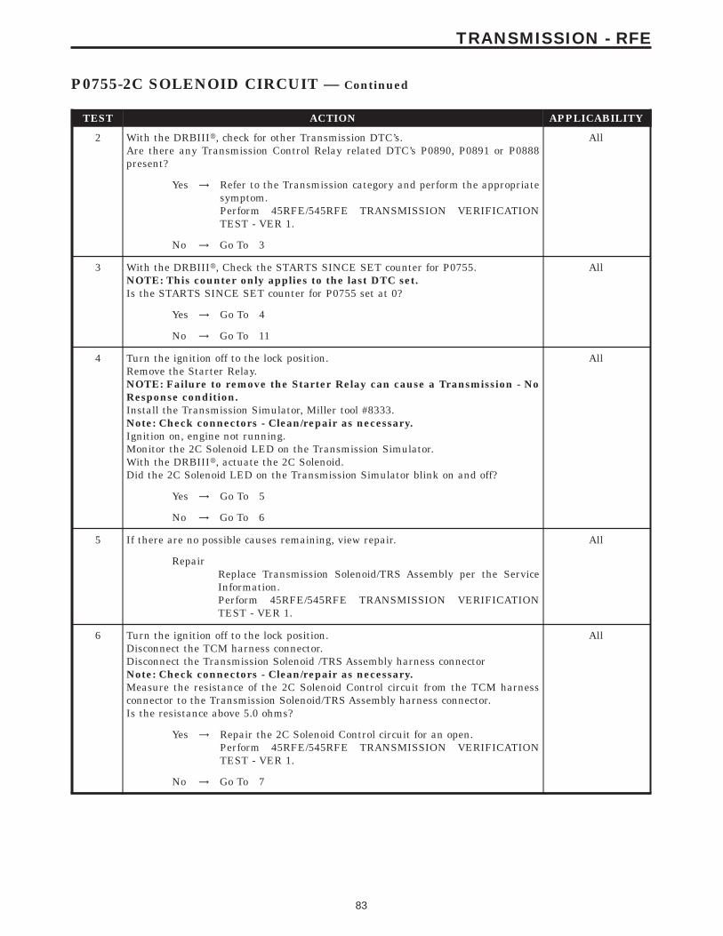
TEST ACTION APPLICABILITY
2 With the DRBIIIt, check for other Transmission DTC’s.Are there any Transmission Control Relay related DTC’s P0890, P0891 or P0888present?
All
Yes → Refer to the Transmission category and perform the appropriatesymptom.Perform 45RFE/545RFE TRANSMISSION VERIFICATIONTEST - VER 1.
No → Go To 3
3 With the DRBIIIt, Check the STARTS SINCE SET counter for P0755.NOTE: This counter only applies to the last DTC set.Is the STARTS SINCE SET counter for P0755 set at 0?
All
Yes → Go To 4
No → Go To 11
4 Turn the ignition off to the lock position.Remove the Starter Relay.NOTE: Failure to remove the Starter Relay can cause a Transmission - NoResponse condition.Install the Transmission Simulator, Miller tool #8333.Note: Check connectors - Clean/repair as necessary.Ignition on, engine not running.Monitor the 2C Solenoid LED on the Transmission Simulator.With the DRBIIIt, actuate the 2C Solenoid.Did the 2C Solenoid LED on the Transmission Simulator blink on and off?
All
Yes → Go To 5
No → Go To 6
5 If there are no possible causes remaining, view repair. All
RepairReplace Transmission Solenoid/TRS Assembly per the ServiceInformation.Perform 45RFE/545RFE TRANSMISSION VERIFICATIONTEST - VER 1.
6 Turn the ignition off to the lock position.Disconnect the TCM harness connector.Disconnect the Transmission Solenoid /TRS Assembly harness connectorNote: Check connectors - Clean/repair as necessary.Measure the resistance of the 2C Solenoid Control circuit from the TCM harnessconnector to the Transmission Solenoid/TRS Assembly harness connector.Is the resistance above 5.0 ohms?
All
Yes → Repair the 2C Solenoid Control circuit for an open.Perform 45RFE/545RFE TRANSMISSION VERIFICATIONTEST - VER 1.
No → Go To 7
83
TRANSMISSION - RFE
P0755-2C SOLENOID CIRCUIT — Continued

TEST ACTION APPLICABILITY
7 Turn the ignition off to the lock position.Disconnect the TCM harness connector.Disconnect the Transmission Solenoid/TRS Assembly harness connector.Note: Check connectors - Clean/repair as necessary.Measure the resistance between ground and the 2C Solenoid Control circuit.Is the resistance below 5.0 ohms?
All
Yes → Repair the 2C Solenoid Control circuit for a short to ground.Perform 45RFE/545RFE TRANSMISSION VERIFICATIONTEST - VER 1.
No → Go To 8
8 Turn the ignition off to the lock position.Disconnect the TCM harness connector.Disconnect the Transmission Solenoid/TRS Assembly harness connector.Remove the Transmission Control Relay.Note: Check connectors - Clean/repair as necessary.Connect a jumper wire between the Fused B+ circuit and the Transmission ControlRelay Output circuit in the Transmission Control Relay connector.Ignition on, engine not running.Measure the voltage of the 2C Solenoid Control circuit.Is the voltage above 0.5 volt?
All
Yes → Repair the 2C Solenoid Control circuit for a short to voltage.Perform 45RFE/545RFE TRANSMISSION VERIFICATIONTEST - VER 1.
No → Go To 9
9 Turn the ignition off to the lock position.Disconnect the Transmission Solenoid/TRS Assembly harness connector.Remove the Transmission Control Relay.NOTE: Check connectors - Clean/repair as necessary.Connect a jumper wire between the Fused B+ circuit and the Transmission ControlRelay Output circuit in the Transmission Control Relay connector.Ignition on, engine not running.Using a 12-volt test light connected to ground, check the Transmission Control RelayOutput circuit in the Transmission Solenoid/TRS Assembly harness connector.NOTE: The test light must illuminate brightly. Compare the brightness tothat of a direct connection to the battery.Does the test light illuminate brightly?
All
Yes → Go To 10
No → Repair the Transmission Control Relay Output circuit for an openor high resistance.Perform 45RFE/545RFE TRANSMISSION VERIFICATIONTEST - VER 1.
10 Using the schematics as a guide, inspect the wiring and connectors. Repair asnecessary. Pay particular attention to all power and ground circuits.If there are no possible causes remaining, view repair.
All
RepairReplace the Transmission Control Module per the Service Infor-mation. WITH THE DRBIIIt PERFORM QUICK LEARN.Perform 45RFE/545RFE TRANSMISSION VERIFICATIONTEST - VER 1.
84
TRANSMISSION - RFE
P0755-2C SOLENOID CIRCUIT — Continued

TEST ACTION APPLICABILITY
11 The conditions necessary to set this DTC are not present at this time.Using the schematics as a guide, inspect the wiring and connectors specific to thiscircuit.Wiggle the wires while checking for shorts and open circuits.With the DRBIIIt, check the EATX DTC EVENT DATA to help identify theconditions in which the DTC was set.Were there any problems found?
All
Yes → Repair as necessaryPerform 45RFE/545RFE TRANSMISSION VERIFICATIONTEST - VER 1.
No → Test Complete.
85
TRANSMISSION - RFE
P0755-2C SOLENOID CIRCUIT — Continued

Symptom:P0760-OD SOLENOID CIRCUIT
When Monitored and Set Condition:
P0760-OD SOLENOID CIRCUIT
When Monitored: Initially at power-up, then every 10 seconds thereafter. It will also betested immediately after a gear ratio or pressure switch error is detected.
Set Condition: After three consecutive solenoid continuity tests failures. After one failureif a test is run in response to a gear ratio or pressure switch error.
POSSIBLE CAUSES
RELATED RELAY DTC’S PRESENT
TRANSMISSION CONTROL RELAY OUTPUT CIRCUIT OPEN
OD SOLENOID CONTROL CIRCUIT OPEN
OD SOLENOID CONTROL CIRCUIT SHORT TO GROUND
OD SOLENOID CONTROL CIRCUIT SHORT TO VOLTAGE
TRANSMISSION SOLENOID/TRS ASSEMBLY
TRANSMISSION CONTROL MODULE
INTERMITTENT WIRING AND CONNECTORS
TEST ACTION APPLICABILITY
1 NOTE: Low fluid level can be the cause of many transmission problems. Ifthe fluid level is low locate and repair the leak then check and adjust thefluid level per the Service Information.NOTE: Always perform diagnostics with a fully charged battery to avoidfalse symptoms.With the DRBIIIt, read the engine DTC’s. Check and repair all engine DTC’s priorto performing transmission symptom diagnostics.With the DRBIIIt, read Transmission DTC’s. Record all DTC’s and 1 Trip Failures.NOTE: Diagnose 1 Trip Failures as a fully matured DTC.Using the wiring diagram/schematic as a guide, inspect the wiring and connectors.Repair as necessary.Perform the Shift Lever Position Test. If the test does not pass, refer to Symptom testfor P0706 Check Shifter Signal.For Gear Ratio DTC’s, check and record all CVI’s.Most DTC’s set on start up but some must be set by driving the vehicle such that alldiagnostic monitors have run.NOTE: Verify the flash level of the transmission controller. Some problemsare corrected by software upgrades to the transmission controller.NOTE: Check for applicable TSB’s related to the problem.Perform this procedure prior to Symptom diagnosis.
All
ContinueGo To 2
86
TRANSMISSION - RFE

TEST ACTION APPLICABILITY
2 With the DRBIIIt, check for other transmission DTC’s.Are there any Transmission Control Relay related DTC’s P0890, P0891 or P0888present.
All
Yes → Refer to the Transmission category and perform the appropriatesymptom.Perform 45RFE/545RFE TRANSMISSION VERIFICATIONTEST - VER 1.
No → Go To 3
3 With the DRBIIIt, Check the STARTS SINCE SET counter for P0760.NOTE: This counter only applies to the last DTC set.Is the STARTS SINCE SET counter for P0760 set at 0?
All
Yes → Go To 4
No → Go To 11
4 Turn the ignition off to the lock position.Remove the Starter Relay from the PDC.NOTE: Failure to remove the Starter Relay can cause a Transmission - NoResponse condition.Install the Transmission Simulator, Miller tool #8333.Note: Check connectors - Clean/repair as necessary.Ignition on, engine not running.Monitor the OD Solenoid LED on the Transmission Simulator.With the DRBIIIt, actuate the OD Solenoid.Did the OD Solenoid LED on the Transmission Simulator blink on and off?
All
Yes → Go To 5
No → Go To 6
5 If there are no possible causes remaining, view repair. All
RepairReplace Transmission Solenoid/TRS Assembly per the ServiceInformation.Perform 45RFE/545RFE TRANSMISSION VERIFICATIONTEST - VER 1.
6 Turn the ignition off to the lock position.Disconnect the TCM harness connector.Disconnect the Transmission Solenoid /TRS Assembly harness connectorNote: Check connectors - Clean/repair as necessary.Measure the resistance of the OD Solenoid Control circuit from the TCM harnessconnector to the Transmission Solenoid/TRS Assembly harness connector.Is the resistance above 5.0 ohms?
All
Yes → Repair the OD Solenoid Control circuit for an open.Perform 45RFE/545RFE TRANSMISSION VERIFICATIONTEST - VER 1.
No → Go To 7
87
TRANSMISSION - RFE
P0760-OD SOLENOID CIRCUIT — Continued

TEST ACTION APPLICABILITY
7 Turn the ignition off to the lock position.Disconnect the TCM harness connector.Disconnect the Transmission Solenoid/TRS Assembly harness connector.Note: Check connectors - Clean/repair as necessary.Measure the resistance between ground and the OD Solenoid Control circuit.Is the resistance below 5.0 ohms?
All
Yes → Repair the OD Solenoid Control circuit for a short to ground.Perform 45RFE/545RFE TRANSMISSION VERIFICATIONTEST - VER 1.
No → Go To 8
8 Turn the ignition off to the lock position.Disconnect the TCM harness connector.Disconnect the Solenoid/TRS Assembly harness connector.Remove the Transmission Control Relay.Note: Check connectors - Clean/repair as necessary.Connect a jumper wire between the Fused B+ circuit and the Transmission ControlRelay Output circuit in the Transmission Control Relay connector.Ignition on, engine not running.Measure the voltage of the OD Solenoid Control circuit.Is the voltage above 0.5 volt?
All
Yes → Repair the OD Solenoid Control circuit for a short to voltage.Perform 45RFE/545RFE TRANSMISSION VERIFICATIONTEST - VER 1.
No → Go To 9
9 Turn the ignition off to the lock position.Disconnect the Transmission Solenoid/TRS Assembly harness connector.Remove the Transmission Control Relay.Connect a jumper wire between the Fused B+ circuit and the Transmission ControlRelay Output circuit in the Transmission Control Relay connector.Ignition on, engine not running.Using a 12-volt test light connected to ground, check the Transmission Control RelayOutput circuit in the Solenoid/TRS Assembly harness connector.NOTE: The test light must illuminate brightly. Compare the brightness tothat of a direct connection to the battery.Does the test light illuminate brightly?
All
Yes → Go To 10
No → Repair the Transmission Control Relay Output circuit for an openor high resistance.Perform 45RFE/545RFE TRANSMISSION VERIFICATIONTEST - VER 1.
10 Using the schematics as a guide, inspect the wiring and connectors. Repair asnecessary. Pay particular attention to all power and ground circuits.If there are no possible causes remaining, view repair.
All
RepairReplace the Transmission Control Module per the Service Infor-mation. WITH THE DRBIIIt PERFORM QUICK LEARN.Perform 45RFE/545RFE TRANSMISSION VERIFICATIONTEST - VER 1.
88
TRANSMISSION - RFE
P0760-OD SOLENOID CIRCUIT — Continued

TEST ACTION APPLICABILITY
11 The conditions necessary to set this DTC are not present at this time.Using the schematics as a guide, inspect the wiring and connectors specific to thiscircuit.Wiggle the wires while checking for shorts and open circuits.With the DRBIIIt, check the EATX DTC EVENT DATA to help identify theconditions in which the DTC was set.Were there any problems found?
All
Yes → Repair as necessary.Perform 45RFE/545RFE TRANSMISSION VERIFICATIONTEST - VER 1.
No → Test Complete.
89
TRANSMISSION - RFE
P0760-OD SOLENOID CIRCUIT — Continued

Symptom:P0765-UD SOLENOID CIRCUIT
When Monitored and Set Condition:
P0765-UD SOLENOID CIRCUIT
When Monitored: Initially at power-up, then every 10 seconds thereafter. It will also betested immediately after a gear ratio or pressure switch error is detected.
Set Condition: After three consecutive solenoid continuity tests failures. After one failureif a test is run in response to a gear ratio or pressure switch error.
POSSIBLE CAUSES
RELATED RELAY DTC’S PRESENT
TRANSMISSION CONTROL RELAY OUTPUT CIRCUIT OPEN
UD SOLENOID CONTROL CIRCUIT OPEN
UD SOLENOID CONTROL CIRCUIT SHORT TO GROUND
UD SOLENOID CONTROL CIRCUIT SHORT TO VOLTAGE
TRANSMISSION SOLENOID/TRS ASSEMBLY
TRANSMISSION CONTROL MODULE
INTERMITTENT WIRING AND CONNECTORS
TEST ACTION APPLICABILITY
1 NOTE: Low fluid level can be the cause of many transmission problems. Ifthe fluid level is low locate and repair the leak then check and adjust thefluid level per the Service Information.NOTE: Always perform diagnostics with a fully charged battery to avoidfalse symptoms.With the DRBIIIt, read the engine DTC’s. Check and repair all engine DTC’s priorto performing transmission symptom diagnostics.With the DRBIIIt, read Transmission DTC’s. Record all DTC’s and 1 Trip Failures.NOTE: Diagnose 1 Trip Failures as a fully matured DTC.Using the wiring diagram/schematic as a guide, inspect the wiring and connectors.Repair as necessary.Perform the Shift Lever Position Test. If the test does not pass, refer to Symptom testfor P0706 Check Shifter Signal.For Gear Ratio DTC’s, check and record all CVI’s.Most DTC’s set on start up but some must be set by driving the vehicle such that alldiagnostic monitors have run.NOTE: Verify the flash level of the transmission controller. Some problemsare corrected by software upgrades to the transmission controller.NOTE: Check for applicable TSB’s related to the problem.Perform this procedure prior to Symptom diagnosis.
All
ContinueGo To 2
90
TRANSMISSION - RFE

TEST ACTION APPLICABILITY
2 With the DRBIIIt, check for other transmission DTC’s.Are there any Transmission Control Relay related DTCs P0890, P0891or P0888present?
All
Yes → Refer to the Transmission category and perform the appropriatesymptom.Perform 45RFE/545RFE TRANSMISSION VERIFICATIONTEST - VER 1.
No → Go To 3
3 With the DRBIIIt, Check the STARTS SINCE SET counter for P0765NOTE: This counter only applies to the last DTC set.Is the STARTS SINCE SET counter for P0765 set at 0?
All
Yes → Go To 4
No → Go To 11
4 Turn the ignition off to the lock position.Remove the Starter Relay.NOTE: Failure to remove the Starter Relay can cause a Transmission - NoResponse condition.Install the Transmission Simulator, Miller tool #8333.Note: Check connectors - Clean/repair as necessary.Ignition on, engine not running.Monitor the UD Solenoid LED on the Transmission Simulator.With the DRBIIIt, actuate the UD Solenoid.Did the UD Solenoid LED on the Transmission Simulator blink on and off?
All
Yes → Go To 5
No → Go To 6
5 If there are no possible causes remaining, view repair. All
RepairReplace Transmission Solenoid/TRS Assembly per the ServiceInformation.Perform 45RFE/545RFE TRANSMISSION VERIFICATIONTEST - VER 1.
6 Turn the ignition off to the lock position.Disconnect the TCM harness connector.Disconnect the Transmission Solenoid /TRS Assembly harness connectorNote: Check connectors - Clean/repair as necessary.Measure the resistance of the UD Solenoid Control circuit between the TCM harnessconnector and the Transmission Solenoid/TRS Assembly harness connector.Is the resistance above 5.0 ohms?
All
Yes → Repair the UD Solenoid Control circuit for an open.Perform 45RFE/545RFE TRANSMISSION VERIFICATIONTEST - VER 1.
No → Go To 7
91
TRANSMISSION - RFE
P0765-UD SOLENOID CIRCUIT — Continued
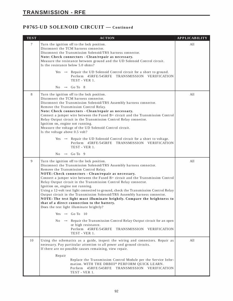
TEST ACTION APPLICABILITY
7 Turn the ignition off to the lock position.Disconnect the TCM harness connector.Disconnect the Transmission Solenoid/TRS harness connector.Note: Check connectors - Clean/repair as necessary.Measure the resistance between ground and the UD Solenoid Control circuit.Is the resistance below 5.0 ohms?
All
Yes → Repair the UD Solenoid Control circuit for a short to ground.Perform 45RFE/545RFE TRANSMISSION VERIFICATIONTEST - VER 1.
No → Go To 8
8 Turn the ignition off to the lock position.Disconnect the TCM harness connector.Disconnect the Transmission Solenoid/TRS Assembly harness connector.Remove the Transmission Control Relay.Note: Check connectors - Clean/repair as necessary.Connect a jumper wire between the Fused B+ circuit and the Transmission ControlRelay Output circuit in the Transmission Control Relay connector.Ignition on, engine not running.Measure the voltage of the UD Solenoid Control circuit.Is the voltage above 0.5 volt?
All
Yes → Repair the UD Solenoid Control circuit for a short to voltage.Perform 45RFE/545RFE TRANSMISSION VERIFICATIONTEST - VER 1.
No → Go To 9
9 Turn the ignition off to the lock position.Disconnect the Transmission Solenoid/TRS Assembly harness connector.Remove the Transmission Control Relay.NOTE: Check connectors - Clean/repair as necessary.Connect a jumper wire between the Fused B+ circuit and the Transmission ControlRelay Output circuit in the Transmission Control Relay connector.Ignition on, engine not running.Using a 12-volt test light connected to ground, check the Transmission Control RelayOutput circuit in the Transmission Solenoid/TRS Assembly harness connector.NOTE: The test light must illuminate brightly. Compare the brightness tothat of a direct connection to the battery.Does the test light illuminate brightly?
All
Yes → Go To 10
No → Repair the Transmission Control Relay Output circuit for an openor high resistance.Perform 45RFE/545RFE TRANSMISSION VERIFICATIONTEST - VER 1.
10 Using the schematics as a guide, inspect the wiring and connectors. Repair asnecessary. Pay particular attention to all power and ground circuits.If there are no possible causes remaining, view repair.
All
RepairReplace the Transmission Control Module per the Service Infor-mation. WITH THE DRBIIIt PERFORM QUICK LEARN.Perform 45RFE/545RFE TRANSMISSION VERIFICATIONTEST - VER 1.
92
TRANSMISSION - RFE
P0765-UD SOLENOID CIRCUIT — Continued

TEST ACTION APPLICABILITY
11 The conditions necessary to set this DTC are not present at this time.Using the schematics as a guide, inspect the wiring and connectors specific to thiscircuit.Wiggle the wires while checking for shorts and open circuits.With the DRBIIIt, check the EATX DTC EVENT DATA to help identify theconditions in which the DTC was set.Were there any problems found?
All
Yes → Repair as necessary.Perform 45RFE/545RFE TRANSMISSION VERIFICATIONTEST - VER 1.
No → Test Complete.
93
TRANSMISSION - RFE
P0765-UD SOLENOID CIRCUIT — Continued

Symptom:P0770-4C SOLENOID CIRCUIT
When Monitored and Set Condition:
P0770-4C SOLENOID CIRCUIT
When Monitored: Initially at power-up, then every 10 seconds thereafter. It will also betested immediately after a gear ratio or pressure switch error is detected.
Set Condition: After three consecutive solenoid continuity tests failures. After one failureif a test is run in response to a gear ratio or pressure switch error.
POSSIBLE CAUSES
RELATED RELAY DTC’S PRESENT
TRANSMISSION CONTROL RELAY OUTPUT CIRCUIT OPEN
4C SOLENOID CONTROL CIRCUIT OPEN
4C SOLENOID CONTROL CIRCUIT SHORT TO GROUND
4C SOLENOID CONTROL CIRCUIT SHORT TO VOLTAGE
TRANSMISSION SOLENOID/TRS ASSEMBLY
TRANSMISSION CONTROL MODULE
INTERMITTENT WIRING AND CONNECTORS
TEST ACTION APPLICABILITY
1 NOTE: Low fluid level can be the cause of many transmission problems. Ifthe fluid level is low locate and repair the leak then check and adjust thefluid level per the Service Information.NOTE: Always perform diagnostics with a fully charged battery to avoidfalse symptoms.With the DRBIIIt, read the engine DTC’s. Check and repair all engine DTC’s priorto performing transmission symptom diagnostics.With the DRBIIIt, read Transmission DTC’s. Record all DTC’s and 1 Trip Failures.NOTE: Diagnose 1 Trip Failures as a fully matured DTC.Using the wiring diagram/schematic as a guide, inspect the wiring and connectors.Repair as necessary.Perform the Shift Lever Position Test. If the test does not pass, refer to Symptom testfor P0706 Check Shifter Signal.For Gear Ratio DTC’s, check and record all CVI’s.Most DTC’s set on start up but some must be set by driving the vehicle such that alldiagnostic monitors have run.NOTE: Verify the flash level of the transmission controller. Some problemsare corrected by software upgrades to the transmission controller.NOTE: Check for applicable TSB’s related to the problem.Perform this procedure prior to Symptom diagnosis.
All
ContinueGo To 2
94
TRANSMISSION - RFE
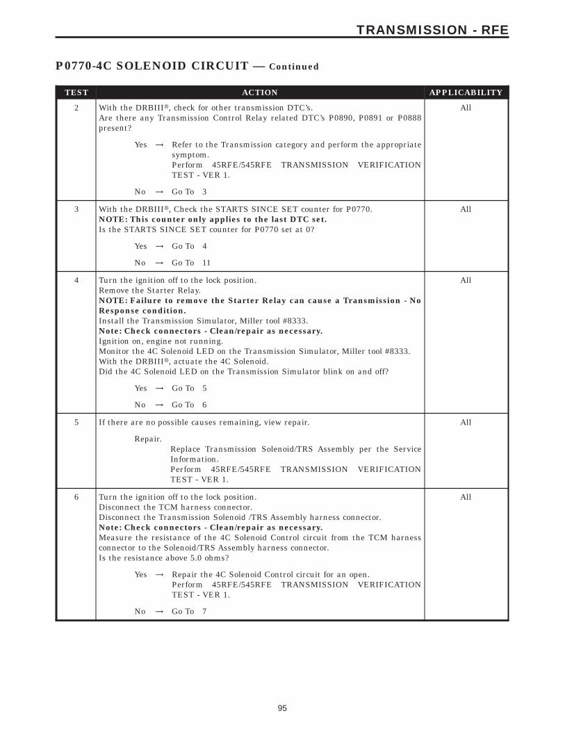
TEST ACTION APPLICABILITY
2 With the DRBIIIt, check for other transmission DTC’s.Are there any Transmission Control Relay related DTC’s P0890, P0891 or P0888present?
All
Yes → Refer to the Transmission category and perform the appropriatesymptom.Perform 45RFE/545RFE TRANSMISSION VERIFICATIONTEST - VER 1.
No → Go To 3
3 With the DRBIIIt, Check the STARTS SINCE SET counter for P0770.NOTE: This counter only applies to the last DTC set.Is the STARTS SINCE SET counter for P0770 set at 0?
All
Yes → Go To 4
No → Go To 11
4 Turn the ignition off to the lock position.Remove the Starter Relay.NOTE: Failure to remove the Starter Relay can cause a Transmission - NoResponse condition.Install the Transmission Simulator, Miller tool #8333.Note: Check connectors - Clean/repair as necessary.Ignition on, engine not running.Monitor the 4C Solenoid LED on the Transmission Simulator, Miller tool #8333.With the DRBIIIt, actuate the 4C Solenoid.Did the 4C Solenoid LED on the Transmission Simulator blink on and off?
All
Yes → Go To 5
No → Go To 6
5 If there are no possible causes remaining, view repair. All
Repair.Replace Transmission Solenoid/TRS Assembly per the ServiceInformation.Perform 45RFE/545RFE TRANSMISSION VERIFICATIONTEST - VER 1.
6 Turn the ignition off to the lock position.Disconnect the TCM harness connector.Disconnect the Transmission Solenoid /TRS Assembly harness connector.Note: Check connectors - Clean/repair as necessary.Measure the resistance of the 4C Solenoid Control circuit from the TCM harnessconnector to the Solenoid/TRS Assembly harness connector.Is the resistance above 5.0 ohms?
All
Yes → Repair the 4C Solenoid Control circuit for an open.Perform 45RFE/545RFE TRANSMISSION VERIFICATIONTEST - VER 1.
No → Go To 7
95
TRANSMISSION - RFE
P0770-4C SOLENOID CIRCUIT — Continued

TEST ACTION APPLICABILITY
7 Turn the ignition off to the lock position.Disconnect the TCM harness connector.Disconnect the Transmission Solenoid/TRS Assembly harness connector.Note: Check connectors - Clean/repair as necessary.Measure the resistance between ground and the 4C Solenoid Control circuit.Is the resistance below 5.0 ohms?
All
Yes → Repair the 4C Solenoid Control circuit for a short to ground.Perform 45RFE/545RFE TRANSMISSION VERIFICATIONTEST - VER 1.
No → Go To 8
8 Turn the ignition off to the lock position.Disconnect the Transmission Control Module harness connector.Disconnect the Transmission Solenoid/TRS Assembly harness connector.Remove the Transmission Control Relay.Note: Check connectors - Clean/repair as necessary.Connect a jumper wire between the Fused B+ circuit and the Transmission ControlRelay Output circuit in the Transmission Control Relay connector.Ignition on, engine not running.Measure the voltage of the 4C Solenoid Control circuit.Is the voltage above 0.5 volt?
All
Yes → Repair the 4C Solenoid Control circuit for a short to voltage.Perform 45RFE/545RFE TRANSMISSION VERIFICATIONTEST - VER 1.
No → Go To 9
9 Turn the ignition off to the lock position.Disconnect the Transmission Solenoid/TRS Assembly harness connector.Remove the Transmission Control Relay.Connect a jumper wire between the Fused B+ circuit and the Transmission ControlRelay Output circuit in the Transmission Control Relay connector.Ignition on, engine not running.Using a 12-volt test light connected to ground, check the Transmission Control RelayOutput circuit in the Solenoid/TRS Assembly harness connector.NOTE: The test light must illuminate brightly. Compare the brightness tothat of a direct connection to the battery.Does the test light illuminate brightly?
All
Yes → Go To 10
No → Repair the Transmission Control Relay Output circuit for an openor high resistance.Perform 45RFE/545RFE TRANSMISSION VERIFICATIONTEST - VER 1.
10 Using the schematics as a guide, inspect the wiring and connectors. Repair asnecessary. Pay particular attention to all power and ground circuits.If there are no possible causes remaining, view repair.
All
RepairReplace the Transmission Control Module per the Service Infor-mation. WITH THE DRBIIIt PERFORM QUICK LEARN.Perform 45RFE/545RFE TRANSMISSION VERIFICATIONTEST - VER 1.
96
TRANSMISSION - RFE
P0770-4C SOLENOID CIRCUIT — Continued
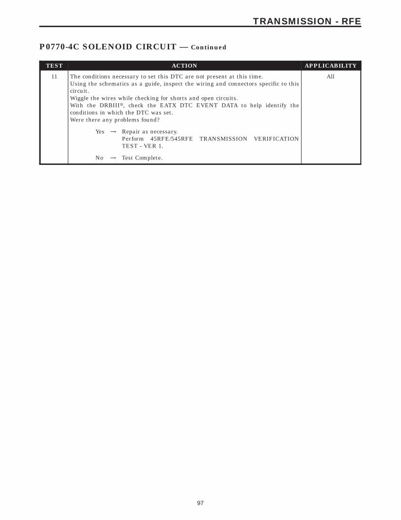
TEST ACTION APPLICABILITY
11 The conditions necessary to set this DTC are not present at this time.Using the schematics as a guide, inspect the wiring and connectors specific to thiscircuit.Wiggle the wires while checking for shorts and open circuits.With the DRBIIIt, check the EATX DTC EVENT DATA to help identify theconditions in which the DTC was set.Were there any problems found?
All
Yes → Repair as necessary.Perform 45RFE/545RFE TRANSMISSION VERIFICATIONTEST - VER 1.
No → Test Complete.
97
TRANSMISSION - RFE
P0770-4C SOLENOID CIRCUIT — Continued
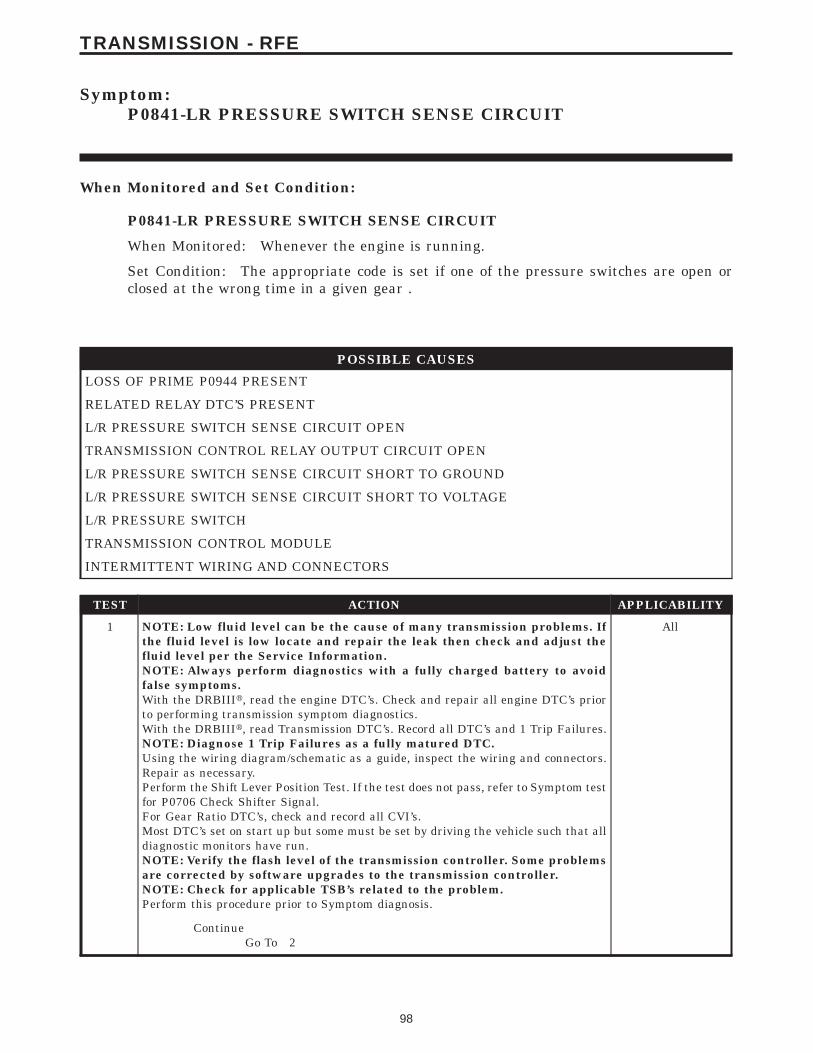
Symptom:P0841-LR PRESSURE SWITCH SENSE CIRCUIT
When Monitored and Set Condition:
P0841-LR PRESSURE SWITCH SENSE CIRCUIT
When Monitored: Whenever the engine is running.
Set Condition: The appropriate code is set if one of the pressure switches are open orclosed at the wrong time in a given gear .
POSSIBLE CAUSES
LOSS OF PRIME P0944 PRESENT
RELATED RELAY DTC’S PRESENT
L/R PRESSURE SWITCH SENSE CIRCUIT OPEN
TRANSMISSION CONTROL RELAY OUTPUT CIRCUIT OPEN
L/R PRESSURE SWITCH SENSE CIRCUIT SHORT TO GROUND
L/R PRESSURE SWITCH SENSE CIRCUIT SHORT TO VOLTAGE
L/R PRESSURE SWITCH
TRANSMISSION CONTROL MODULE
INTERMITTENT WIRING AND CONNECTORS
TEST ACTION APPLICABILITY
1 NOTE: Low fluid level can be the cause of many transmission problems. Ifthe fluid level is low locate and repair the leak then check and adjust thefluid level per the Service Information.NOTE: Always perform diagnostics with a fully charged battery to avoidfalse symptoms.With the DRBIIIt, read the engine DTC’s. Check and repair all engine DTC’s priorto performing transmission symptom diagnostics.With the DRBIIIt, read Transmission DTC’s. Record all DTC’s and 1 Trip Failures.NOTE: Diagnose 1 Trip Failures as a fully matured DTC.Using the wiring diagram/schematic as a guide, inspect the wiring and connectors.Repair as necessary.Perform the Shift Lever Position Test. If the test does not pass, refer to Symptom testfor P0706 Check Shifter Signal.For Gear Ratio DTC’s, check and record all CVI’s.Most DTC’s set on start up but some must be set by driving the vehicle such that alldiagnostic monitors have run.NOTE: Verify the flash level of the transmission controller. Some problemsare corrected by software upgrades to the transmission controller.NOTE: Check for applicable TSB’s related to the problem.Perform this procedure prior to Symptom diagnosis.
All
ContinueGo To 2
98
TRANSMISSION - RFE

TEST ACTION APPLICABILITY
2 With the DRBIIIt, check for other Transmission DTC’s.Are there any Transmission Control Relay related DTC’s P0890, P0891, or P0888present?.
All
Yes → Refer to symptom list and perform test for the related Transmis-sion Control Relay DTC (s).Perform 45RFE/545RFE TRANSMISSION VERIFICATIONTEST - VER 1.
No → Go To 3
3 With the DRBIIIt, check for other Transmission DTC’s.Is DTC P0944 present in addition to the DTC that you are diagnosing?
All
Yes → Refer to symptom list and perform test for P0944.Perform 45RFE/545RFE TRANSMISSION VERIFICATIONTEST - VER 1.
No → Go To 4
4 With the DRBIIIt, Check the STARTS SINCE SET counter for P0841.NOTE: This counter only applies to the last DTC set.Is the STARTS SINCE SET counter 2 or less?
All
Yes → Go To 5
No → Go To 12
5 Turn the ignition off to the lock position.Remove the Starter Relay from the PDC.NOTE: Failure to remove the Starter Relay can cause a Transmission - NoResponse condition.Install the Transmission Simulator, Miller tool #8333.Note: Check connectors - Clean/repair as necessary.Ignition on, engine not running.With the Transmission Simulator, turn the Pressure Switch selector switch to LR.With the DRBIIIt, monitor the LR Pressure Switch state while pressing the PressureSwitch Test button on the Transmission Simulator.Did the state of the UD Pressure Switch change while pressing the Pressure SwitchTest button?
All
Yes → Go To 6
No → Go To 7
6 If there are no possible causes remaining, view repair. All
RepairReplace the Transmission Solenoid/TRS Assembly per the ServiceInformation.Perform 45RFE/545RFE TRANSMISSION VERIFICATIONTEST - VER 1.
99
TRANSMISSION - RFE
P0841-LR PRESSURE SWITCH SENSE CIRCUIT — Continued

TEST ACTION APPLICABILITY
7 Turn the ignition off to the lock position.Disconnect the TCM harness connector.Disconnect the Transmission Solenoid /TRS Assembly harness connector.Note: Check connectors - Clean/repair as necessary.Measure the resistance of the L/R Pressure Switch Sense circuit from the TCMharness connector to the Solenoid/TRS Assembly harness connector.Is the resistance above 5.0 ohms?
All
Yes → Repair the L/R Pressure Switch Sense circuit for an open.Perform 45RFE/545RFE TRANSMISSION VERIFICATIONTEST - VER 1.
No → Go To 8
8 Turn the ignition off to the lock position.Disconnect the TCM harness connector.Disconnect the Transmission Solenoid/TRS Assembly harness connector.Note: Check connectors - Clean/repair as necessary.Measure the resistance between ground and the L/R Pressure Switch Sense circuit.Is the resistance below 5.0 ohms?
All
Yes → Repair the L/R Pressure Switch Sense circuit for a short toground.Perform 45RFE/545RFE TRANSMISSION VERIFICATIONTEST - VER 1.
No → Go To 9
9 Turn the ignition off to the lock position.Disconnect the TCM harness connector.Disconnect the Transmission Solenoid/TRS Assembly harness connector.Remove the Transmission Control Relay.Note: Check connectors - Clean/repair as necessary.Connect a jumper wire between the Fused B+ circuit and the Transmission ControlRelay Output circuit in the Transmission Control Relay connector.Ignition on, engine not running.Measure the voltage of the L/R Pressure Switch Sense circuit in the TCM harnessconnector.Is the voltage above 0.5 volt?
All
Yes → Repair the L/R Pressure Switch Sense circuit for a short tovoltage.Perform 45RFE/545RFE TRANSMISSION VERIFICATIONTEST - VER 1.
No → Go To 10
100
TRANSMISSION - RFE
P0841-LR PRESSURE SWITCH SENSE CIRCUIT — Continued

TEST ACTION APPLICABILITY
10 Turn the ignition off to the lock position.Disconnect the Transmission Solenoid/TRS Assembly harness connector.Remove the Transmission Control Relay.Connect a jumper wire between the Fused B+ circuit and the Transmission ControlRelay Output circuit in the Transmission Control Relay connector.Note: Check connectors - Clean/repair as necessary.Ignition on, engine not running.Using a 12-volt test light connected to ground, check the Transmission Control RelayOutput circuit in the Transmission Solenoid/TRS Assembly harness connector.NOTE: The test light must illuminate brightly. Compare the brightness tothat of a direct connection to the battery.Does the test light illuminate brightly?
All
Yes → Go To 11
No → Repair the Transmission Control Relay Output circuit for anopen. If the fuse is open make sure to check for a short to ground.Perform 45RFE/545RFE TRANSMISSION VERIFICATIONTEST - VER 1.
11 Using the schematics as a guide, inspect the wiring and connectors. Repair asnecessary. Pay particular attention to all power and ground circuits.If there are no possible causes remaining, view repair.
All
RepairReplace the Transmission Control Module per the Service Infor-mation. WITH THE DRBIIIt PERFORM QUICK LEARNPerform 45RFE/545RFE TRANSMISSION VERIFICATIONTEST - VER 1.
12 The conditions necessary to set this DTC are not present at this time.Using the schematics as a guide, inspect the wiring and connectors specific to thiscircuit.Wiggle the wires while checking for shorts and open circuits.Check for a Primary Oil Filter improperly installed.A dislodged Reverse Carrier Snap Ring will typically set this DTC on heavy throttleacceleration from a dead stop.With the DRBIIIt, check the EATX DTC EVENT DATA to help identify theconditions in which the DTC was set.Were there any problems found?
All
Yes → Repair as necessary.Perform 45RFE/545RFE TRANSMISSION VERIFICATIONTEST - VER 1.
No → Test Complete.
101
TRANSMISSION - RFE
P0841-LR PRESSURE SWITCH SENSE CIRCUIT — Continued

Symptom:P0845-2C HYDRAULIC PRESSURE TEST FAILURE
When Monitored and Set Condition:
P0845-2C HYDRAULIC PRESSURE TEST FAILURE
When Monitored: In any forward gear with engine speed above 1000 RPM shortly aftera shift and every minute thereafter.
Set Condition: After a shift into a forward gear, with engine speed above 1000 RPM, theTCM momentarily turns on element pressure to the Clutch circuits that don’t havepressure to identify the correct Pressure Switch closes. If the Pressure Switch does notclose 2 times, the DTC sets.
POSSIBLE CAUSES
RELATED LINE PRESSURE DTC’S PRESENT
TRANSMISSION SOLENOID/TRS ASSEMBLY
2C PRESSURE SWITCH SENSE CIRCUIT OPEN
5-VOLT SUPPLY CIRCUIT OPEN
POOR LINE PRESSURE SENSOR CONNECTION
TRANSMISSION CONTROL RELAY OUTPUT CIRCUIT OPEN
2C PRESSURE SWITCH SENSE CIRCUIT SHORT TO GROUND
5-VOLT SUPPLY CIRCUIT SHORT TO GROUND
2C PRESSURE SWITCH SENSE CIRCUIT SHORT TO VOLTAGE
EXCESSIVE DEBRIS IN OIL PAN
LINE PRESSURE SENSOR
INTERNAL TRANSMISSION
TRANSMISSION CONTROL MODULE
INTERMITTENT WIRING AND CONNECTORS
102
TRANSMISSION - RFE

TEST ACTION APPLICABILITY
1 NOTE: Low fluid level can be the cause of many transmission problems. Ifthe fluid level is low locate and repair the leak then check and adjust thefluid level per the Service Information.NOTE: Always perform diagnostics with a fully charged battery to avoidfalse symptoms.With the DRBIIIt, read the engine DTC’s. Check and repair all engine DTC’s priorto performing transmission symptom diagnostics.With the DRBIIIt, read Transmission DTC’s. Record all DTC’s and 1 Trip Failures.NOTE: Diagnose 1 Trip Failures as a fully matured DTC.Using the wiring diagram/schematic as a guide, inspect the wiring and connectors.Repair as necessary.Perform the Shift Lever Position Test. If the test does not pass, refer to Symptom testfor P0706 Check Shifter Signal.For Gear Ratio DTC’s, check and record all CVI’s.Most DTC’s set on start up but some must be set by driving the vehicle such that alldiagnostic monitors have run.NOTE: Verify the flash level of the transmission controller. Some problemsare corrected by software upgrades to the transmission controller.NOTE: Check for applicable TSB’s related to the problem.Perform this procedure prior to Symptom diagnosis.
All
ContinueGo To 2
2 With the DRBIIIt, check for other transmission DTC’sIs there any Loss of Prime, and/or Line Pressure Sensor DTCs present?
All
Yes → Refer to Symptom List for the related symptom(s).Perform 45RFE/545RFE TRANSMISSION VERIFICATIONTEST - VER 1.
No → Go To 3
3 With the DRBIIIt, check for other transmission DTC’sIs the DTC P0732 and/or P0846 present also?
All
Yes → Replace the Transmission Solenoid/TRS Assembly per the ServiceInformation.Perform 45RFE/545RFE TRANSMISSION VERIFICATIONTEST - VER 1.
No → Go To 4
4 With the DRBIII, Check the STARTS SINCE SET counter for P0845.NOTE: This counter only applies to the last DTC set.Is the STARTS SINCE SET counter 2 or less?
All
Yes → Go To 5
No → Go To 18
103
TRANSMISSION - RFE
P0845-2C HYDRAULIC PRESSURE TEST FAILURE — Continued

TEST ACTION APPLICABILITY
5 Start the engine.Warm the transmission to 82° C or 180° F.Firmly apply the brakes.With the DRBIIIt, monitor the Line Pressure during the following step.Move the shift lever to each gear position and record the line pressure reading. Allowthe pressure to stabilize for at least 5 seconds in each range.Did the line pressure remain at a steady value between 585 and 655 Kpa or 85 or 95PSI?
All
Yes → Go To 6
No → Go To 10
6 Ignition on, engine not running.With the DRBIIIt, monitor the Line Pressure during the following step.Firmly push the Transmission Line Pressure Sensor connector towards the Trans-mission.Did the Line Pressure change to about 207 kPa or 30 PSI when the connector waspushed?
All
Yes → Disconnect and properly reconnect the Line Pressure Sensorconnector. Inspect terminals and repair as necessary.Perform 45RFE/545RFE TRANSMISSION VERIFICATIONTEST - VER 1.
No → Go To 7
7 Turn the ignition off to the lock position.Remove the Starter Relay.NOTE: Failure to remove the Starter Relay can cause a TCM - No Responsecondition.Install the Transmission Simulator Miller tool# 8333.With the Transmission Simulator select the 9OFF9 position on the 9Input/OutputSpeed9 switch.NOTE: Check connectors - Clean/repair as necessary.Ignition on, engine not running.With the DRBIIIt, monitor the Line Pressure during the following step.Using the Transmission Simulator, set the rotary knob to each of the 3 line pressurepositions.NOTE: All three DRBIIIt Line Pressure readings should be steady and ± 14kPa or 2.0 PSI of the reading specified on the Transmission Simulator.Did the Line Pressure match the specified readings and remain steady in all threepositions?
All
Yes → Replace the Line Pressure Sensor per the Service Information.Perform 45RFE/545RFE TRANSMISSION VERIFICATIONTEST - VER 1.
No → Go To 8
104
TRANSMISSION - RFE
P0845-2C HYDRAULIC PRESSURE TEST FAILURE — Continued
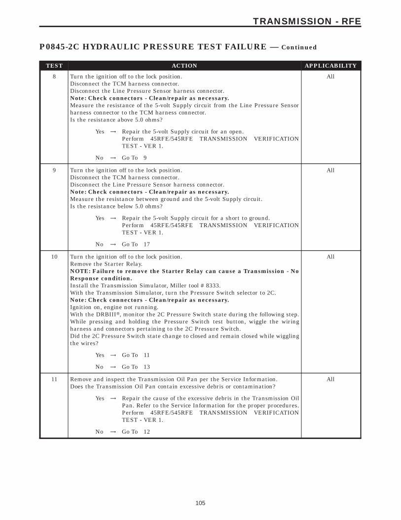
TEST ACTION APPLICABILITY
8 Turn the ignition off to the lock position.Disconnect the TCM harness connector.Disconnect the Line Pressure Sensor harness connector.Note: Check connectors - Clean/repair as necessary.Measure the resistance of the 5-volt Supply circuit from the Line Pressure Sensorharness connector to the TCM harness connector.Is the resistance above 5.0 ohms?
All
Yes → Repair the 5-volt Supply circuit for an open.Perform 45RFE/545RFE TRANSMISSION VERIFICATIONTEST - VER 1.
No → Go To 9
9 Turn the ignition off to the lock position.Disconnect the TCM harness connector.Disconnect the Line Pressure Sensor harness connector.Note: Check connectors - Clean/repair as necessary.Measure the resistance between ground and the 5-volt Supply circuit.Is the resistance below 5.0 ohms?
All
Yes → Repair the 5-volt Supply circuit for a short to ground.Perform 45RFE/545RFE TRANSMISSION VERIFICATIONTEST - VER 1.
No → Go To 17
10 Turn the ignition off to the lock position.Remove the Starter Relay.NOTE: Failure to remove the Starter Relay can cause a Transmission - NoResponse condition.Install the Transmission Simulator, Miller tool # 8333.With the Transmission Simulator, turn the Pressure Switch selector to 2C.Note: Check connectors - Clean/repair as necessary.Ignition on, engine not running.With the DRBIIIt, monitor the 2C Pressure Switch state during the following step.While pressing and holding the Pressure Switch test button, wiggle the wiringharness and connectors pertaining to the 2C Pressure Switch.Did the 2C Pressure Switch state change to closed and remain closed while wigglingthe wires?
All
Yes → Go To 11
No → Go To 13
11 Remove and inspect the Transmission Oil Pan per the Service Information.Does the Transmission Oil Pan contain excessive debris or contamination?
All
Yes → Repair the cause of the excessive debris in the Transmission OilPan. Refer to the Service Information for the proper procedures.Perform 45RFE/545RFE TRANSMISSION VERIFICATIONTEST - VER 1.
No → Go To 12
105
TRANSMISSION - RFE
P0845-2C HYDRAULIC PRESSURE TEST FAILURE — Continued

TEST ACTION APPLICABILITY
12 If there are no possible causes remaining, view repair. All
RepairRepair Internal Transmission as necessary. Disassemble andinspect the Valve Body and repair or replace as necessary. If noproblems are found in the Valve Body, replace the TransmissionSolenoid/TRS Assembly.Perform 45RFE/545RFE TRANSMISSION VERIFICATIONTEST - VER 1.
13 Turn the ignition off to the lock position.Disconnect the TCM harness connector.Disconnect the Transmission Solenoid /TRS Assembly harness connector.Note: Check connectors - Clean/repair as necessary.Measure the resistance of the 2C Pressure Switch Sense circuit from the TCMharness connector to the Transmission Solenoid/TRS Assembly harness connector.Is the resistance above 5.0 ohms?
All
Yes → Repair the 2C Pressure Switch Sense circuit for an open.Perform 45RFE/545RFE TRANSMISSION VERIFICATIONTEST - VER 1.
No → Go To 14
14 Turn the ignition off to the lock position.Disconnect the TCM harness connector.Disconnect the Transmission Solenoid/TRS Assembly harness connector.Note: Check connectors - Clean/repair as necessary.Measure the resistance between ground and the 2C Pressure Switch Sense circuit.Is the resistance below 5.0 ohms?
All
Yes → Repair the 2C Pressure Switch circuit for a short to ground.Perform 45RFE/545RFE TRANSMISSION VERIFICATIONTEST - VER 1.
No → Go To 15
15 Turn the ignition off to the lock position.Disconnect the TCM harness connector.Disconnect the Transmission Solenoid/TRS Assembly harness connector.Remove the Transmission Control Relay.Note: Check connectors - Clean/repair as necessary.Connect a jumper wire between the Fused B+ circuit and the Transmission ControlRelay Output circuit in the Transmission Control Relay connector.Ignition on, engine not running.Measure the voltage of the 2C Pressure Switch Sense circuit in the TCM harnessconnector.Is the voltage above 0.5 volt?
All
Yes → Repair the 2C Pressure Switch Sense circuit for a short to voltage.Perform 45RFE/545RFE TRANSMISSION VERIFICATIONTEST - VER 1.
No → Go To 16
106
TRANSMISSION - RFE
P0845-2C HYDRAULIC PRESSURE TEST FAILURE — Continued
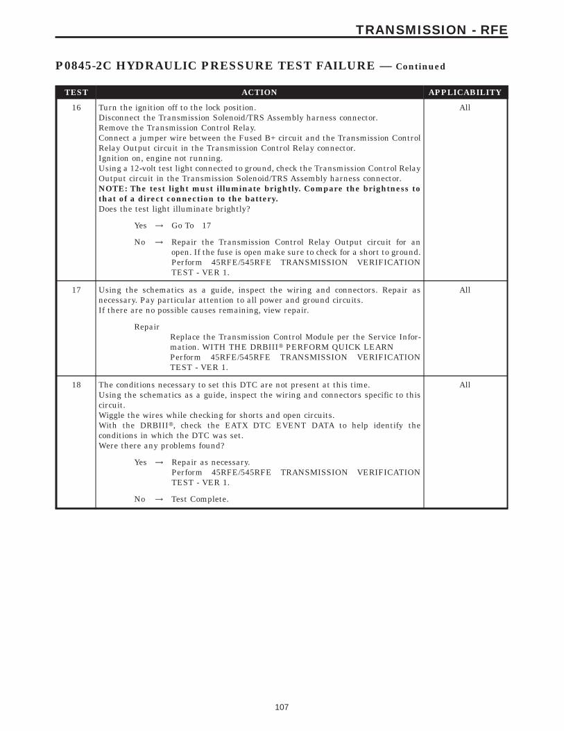
TEST ACTION APPLICABILITY
16 Turn the ignition off to the lock position.Disconnect the Transmission Solenoid/TRS Assembly harness connector.Remove the Transmission Control Relay.Connect a jumper wire between the Fused B+ circuit and the Transmission ControlRelay Output circuit in the Transmission Control Relay connector.Ignition on, engine not running.Using a 12-volt test light connected to ground, check the Transmission Control RelayOutput circuit in the Transmission Solenoid/TRS Assembly harness connector.NOTE: The test light must illuminate brightly. Compare the brightness tothat of a direct connection to the battery.Does the test light illuminate brightly?
All
Yes → Go To 17
No → Repair the Transmission Control Relay Output circuit for anopen. If the fuse is open make sure to check for a short to ground.Perform 45RFE/545RFE TRANSMISSION VERIFICATIONTEST - VER 1.
17 Using the schematics as a guide, inspect the wiring and connectors. Repair asnecessary. Pay particular attention to all power and ground circuits.If there are no possible causes remaining, view repair.
All
RepairReplace the Transmission Control Module per the Service Infor-mation. WITH THE DRBIIIt PERFORM QUICK LEARNPerform 45RFE/545RFE TRANSMISSION VERIFICATIONTEST - VER 1.
18 The conditions necessary to set this DTC are not present at this time.Using the schematics as a guide, inspect the wiring and connectors specific to thiscircuit.Wiggle the wires while checking for shorts and open circuits.With the DRBIIIt, check the EATX DTC EVENT DATA to help identify theconditions in which the DTC was set.Were there any problems found?
All
Yes → Repair as necessary.Perform 45RFE/545RFE TRANSMISSION VERIFICATIONTEST - VER 1.
No → Test Complete.
107
TRANSMISSION - RFE
P0845-2C HYDRAULIC PRESSURE TEST FAILURE — Continued

Symptom:P0846-2C PRESSURE SWITCH SENSE CIRCUIT
When Monitored and Set Condition:
P0846-2C PRESSURE SWITCH SENSE CIRCUIT
When Monitored: Whenever the engine is running.
Set Condition: The appropriate code is set if one of the pressure switches are open orclosed at the wrong time in a given gear .
POSSIBLE CAUSES
RELATED RELAY DTC’S PRESENT
2C PRESSURE SWITCH SENSE CIRCUIT OPEN
TRANSMISSION CONTROL RELAY OUTPUT CIRCUIT OPEN
2C PRESSURE SWITCH SENSE CIRCUIT SHORT TO GROUND
2C PRESSURE SWITCH SENSE CIRCUIT SHORT TO VOLTAGE
2C PRESSURE SWITCH
TRANSMISSION CONTROL MODULE
INTERMITTENT WIRING AND CONNECTORS
TEST ACTION APPLICABILITY
1 NOTE: Low fluid level can be the cause of many transmission problems. Ifthe fluid level is low locate and repair the leak then check and adjust thefluid level per the Service Information.NOTE: Always perform diagnostics with a fully charged battery to avoidfalse symptoms.With the DRBIIIt, read the engine DTC’s. Check and repair all engine DTC’s priorto performing transmission symptom diagnostics.With the DRBIIIt, read Transmission DTC’s. Record all DTC’s and 1 Trip Failures.NOTE: Diagnose 1 Trip Failures as a fully matured DTC.Using the wiring diagram/schematic as a guide, inspect the wiring and connectors.Repair as necessary.Perform the Shift Lever Position Test. If the test does not pass, refer to Symptom testfor P0706 Check Shifter Signal.For Gear Ratio DTC’s, check and record all CVI’s.Most DTC’s set on start up but some must be set by driving the vehicle such that alldiagnostic monitors have run.NOTE: Verify the flash level of the transmission controller. Some problemsare corrected by software upgrades to the transmission controller.NOTE: Check for applicable TSB’s related to the problem.Perform this procedure prior to Symptom diagnosis.
All
ContinueGo To 2
108
TRANSMISSION - RFE

TEST ACTION APPLICABILITY
2 With the DRBIIIt, check for other transmission DTC’s.Are there any Transmission Control Relay related DTC’s P0890, P0891, or P0888present?
All
Yes → Refer to symptom list and perform test for Transmission ControlRelay related DTCs.Perform 45RFE/545RFE TRANSMISSION VERIFICATIONTEST - VER 1.
No → Go To 3
3 With the DRBIIIt, Check the STARTS SINCE SET counter.NOTE: This counter only applies to the last DTC set.Is the STARTS SINCE SET counter for P0846, 2 or less?
All
Yes → Go To 4
No → Go To 11
4 Turn the ignition off to the lock position.Remove the Starter Relay.NOTE: Failure to remove the Starter Relay can cause a TCM - No Responsecondition.Install the Transmission Simulator, Miller tool #8333.Note: Check connectors - Clean/repair as necessary.Ignition on, engine not running.With the Transmission Simulator, turn the Pressure Switch selector switch to 2C.With the DRBIIIt, monitor the 2C Pressure Switch while pressing the PressureSwitch test button on the Transmission Simulator.Did the state of the 2C Pressure Switch change while pressing the Pressure SwitchTest button?
All
Yes → Go To 5
No → Go To 6
5 If there are no possible causes remaining, view repair. All
RepairReplace the Transmission Solenoid/TRS Assembly per the ServiceInformation.Perform 45RFE/545RFE TRANSMISSION VERIFICATIONTEST - VER 1.
6 Turn the ignition off to the lock position.Disconnect the TCM harness connector.Disconnect the Transmission Solenoid /TRS Assembly harness connector.Note: Check connectors - Clean/repair as necessary.Measure the resistance of the 2C Pressure Switch Sense circuit from the TCMharness connector to the Transmission Solenoid/TRS Assembly harness connector.Is the resistance above 5.0 ohms?
All
Yes → Repair the 2C Pressure Switch Sense circuit for an open.Perform 45RFE/545RFE TRANSMISSION VERIFICATIONTEST - VER 1.
No → Go To 7
109
TRANSMISSION - RFE
P0846-2C PRESSURE SWITCH SENSE CIRCUIT — Continued

TEST ACTION APPLICABILITY
7 Turn the ignition off to the lock position.Disconnect the TCM harness connector.Disconnect the Transmission Solenoid/TRS Assembly harness connector.Note: Check connectors - Clean/repair as necessary.Measure the resistance between ground and the 2C Pressure Switch Sense circuit.Is the resistance below 5.0 ohms?
All
Yes → Repair the 2C Pressure Switch Sense circuit for a short to ground.Perform 45RFE/545RFE TRANSMISSION VERIFICATIONTEST - VER 1.
No → Go To 8
8 Turn the ignition off to the lock position.Disconnect the TCM harness connector.Disconnect the Transmission Solenoid/TRS Assembly harness connector.Remove the Transmission Control Relay.Note: Check connectors - Clean/repair as necessary.Connect a jumper wire between the Fused B+ circuit and the Transmission ControlRelay Output circuit in the Transmission Control Relay connector.Ignition on, engine not running.Measure the voltage of the 2C Pressure Switch Sense circuit.Is the voltage above 0.5 volt?
All
Yes → Repair the 2C Pressure Switch Sense circuit for a short to voltage.Perform 45RFE/545RFE TRANSMISSION VERIFICATIONTEST - VER 1.
No → Go To 9
9 Turn the ignition off to the lock position.Disconnect the Transmission Solenoid/TRS Assembly harness connector.Remove the Transmission Control Relay.Note: Check connectors - Clean/repair as necessary.Connect a jumper wire between the Fused B+ circuit and the Transmission ControlRelay Output circuit in the Transmission Control Relay connector.Ignition on, engine not running.Using a 12-volt test light connected to ground, check the Transmission Control RelayOutput circuit in the Solenoid/TRS Assembly harness connector.NOTE: The test light must illuminate brightly. Compare the brightness tothat of a direct connection to the battery.Does the test light illuminate brightly?
All
Yes → Go To 10
No → Repair the Transmission Control Relay Output circuit for anopen. If the fuse is open make sure to check for a short to ground.Perform 45RFE/545RFE TRANSMISSION VERIFICATIONTEST - VER 1.
10 Using the schematics as a guide, inspect the wiring and connectors. Repair asnecessary. Pay particular attention to all power and ground circuits.If there are no possible causes remaining, view repair.
All
RepairReplace the Transmission Control Module per the Service Infor-mation. WITH THE DRBIIIt PERFORM QUICK LEARNPerform 45RFE/545RFE TRANSMISSION VERIFICATIONTEST - VER 1.
110
TRANSMISSION - RFE
P0846-2C PRESSURE SWITCH SENSE CIRCUIT — Continued
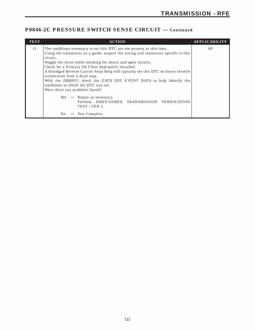
TEST ACTION APPLICABILITY
11 The conditions necessary to set this DTC are not present at this time.Using the schematics as a guide, inspect the wiring and connectors specific to thiscircuit.Wiggle the wires while checking for shorts and open circuits.Check for a Primary Oil Filter improperly installed.A dislodged Reverse Carrier Snap Ring will typically set this DTC on heavy throttleacceleration from a dead stop.With the DRBIIIt, check the EATX DTC EVENT DATA to help identify theconditions in which the DTC was set.Were there any problems found?
All
Yes → Repair as necessary.Perform 45RFE/545RFE TRANSMISSION VERIFICATIONTEST - VER 1.
No → Test Complete.
111
TRANSMISSION - RFE
P0846-2C PRESSURE SWITCH SENSE CIRCUIT — Continued
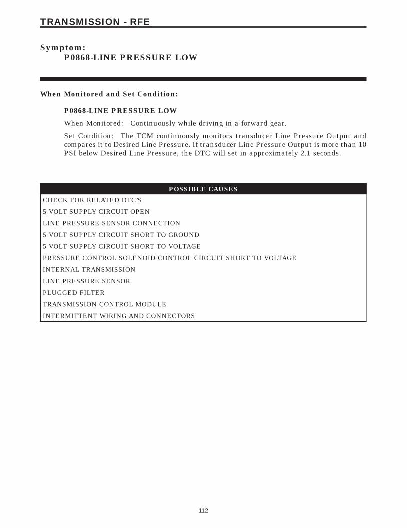
Symptom:P0868-LINE PRESSURE LOW
When Monitored and Set Condition:
P0868-LINE PRESSURE LOW
When Monitored: Continuously while driving in a forward gear.
Set Condition: The TCM continuously monitors transducer Line Pressure Output andcompares it to Desired Line Pressure. If transducer Line Pressure Output is more than 10PSI below Desired Line Pressure, the DTC will set in approximately 2.1 seconds.
POSSIBLE CAUSES
CHECK FOR RELATED DTC’S
5 VOLT SUPPLY CIRCUIT OPEN
LINE PRESSURE SENSOR CONNECTION
5 VOLT SUPPLY CIRCUIT SHORT TO GROUND
5 VOLT SUPPLY CIRCUIT SHORT TO VOLTAGE
PRESSURE CONTROL SOLENOID CONTROL CIRCUIT SHORT TO VOLTAGE
INTERNAL TRANSMISSION
LINE PRESSURE SENSOR
PLUGGED FILTER
TRANSMISSION CONTROL MODULE
INTERMITTENT WIRING AND CONNECTORS
112
TRANSMISSION - RFE
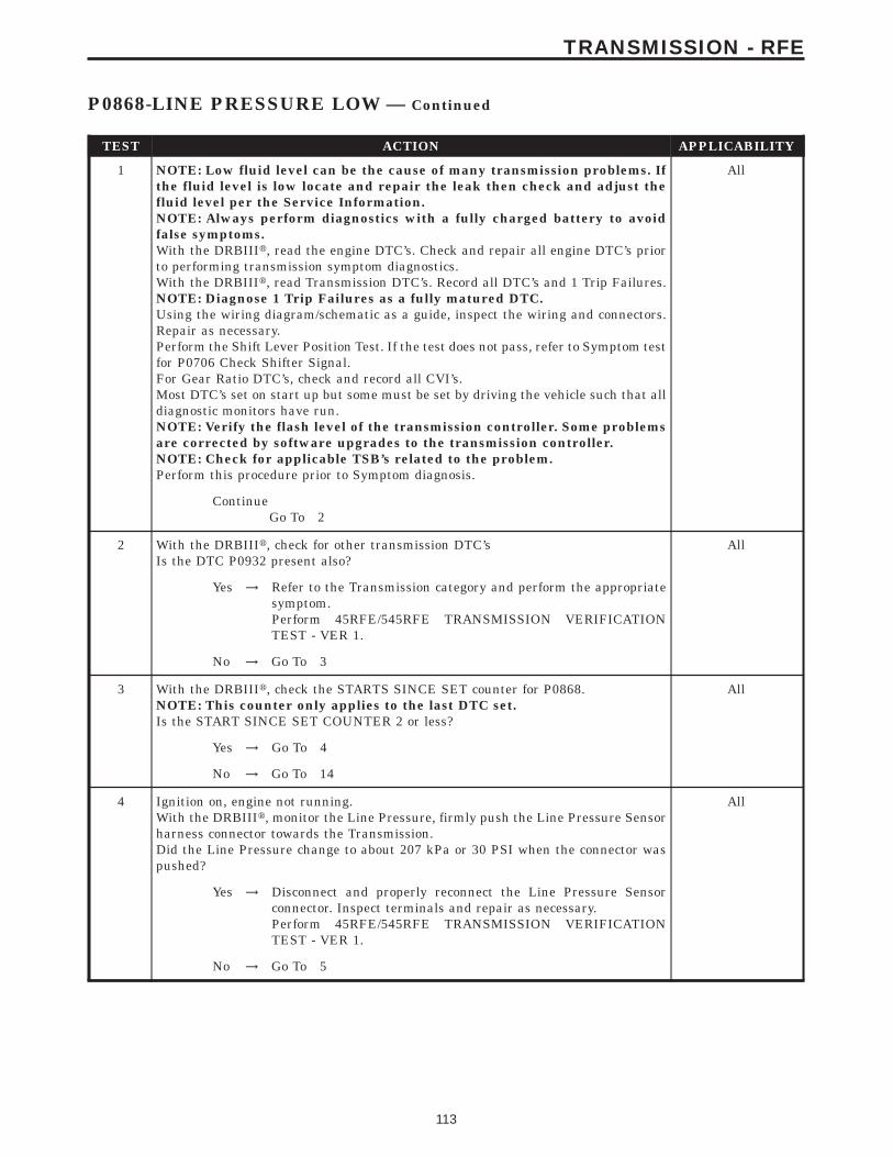
TEST ACTION APPLICABILITY
1 NOTE: Low fluid level can be the cause of many transmission problems. Ifthe fluid level is low locate and repair the leak then check and adjust thefluid level per the Service Information.NOTE: Always perform diagnostics with a fully charged battery to avoidfalse symptoms.With the DRBIIIt, read the engine DTC’s. Check and repair all engine DTC’s priorto performing transmission symptom diagnostics.With the DRBIIIt, read Transmission DTC’s. Record all DTC’s and 1 Trip Failures.NOTE: Diagnose 1 Trip Failures as a fully matured DTC.Using the wiring diagram/schematic as a guide, inspect the wiring and connectors.Repair as necessary.Perform the Shift Lever Position Test. If the test does not pass, refer to Symptom testfor P0706 Check Shifter Signal.For Gear Ratio DTC’s, check and record all CVI’s.Most DTC’s set on start up but some must be set by driving the vehicle such that alldiagnostic monitors have run.NOTE: Verify the flash level of the transmission controller. Some problemsare corrected by software upgrades to the transmission controller.NOTE: Check for applicable TSB’s related to the problem.Perform this procedure prior to Symptom diagnosis.
All
ContinueGo To 2
2 With the DRBIIIt, check for other transmission DTC’sIs the DTC P0932 present also?
All
Yes → Refer to the Transmission category and perform the appropriatesymptom.Perform 45RFE/545RFE TRANSMISSION VERIFICATIONTEST - VER 1.
No → Go To 3
3 With the DRBIIIt, check the STARTS SINCE SET counter for P0868.NOTE: This counter only applies to the last DTC set.Is the START SINCE SET COUNTER 2 or less?
All
Yes → Go To 4
No → Go To 14
4 Ignition on, engine not running.With the DRBIIIt, monitor the Line Pressure, firmly push the Line Pressure Sensorharness connector towards the Transmission.Did the Line Pressure change to about 207 kPa or 30 PSI when the connector waspushed?
All
Yes → Disconnect and properly reconnect the Line Pressure Sensorconnector. Inspect terminals and repair as necessary.Perform 45RFE/545RFE TRANSMISSION VERIFICATIONTEST - VER 1.
No → Go To 5
113
TRANSMISSION - RFE
P0868-LINE PRESSURE LOW — Continued

TEST ACTION APPLICABILITY
5 Turn the ignition off to the lock position.Remove the Starter Relay.NOTE: Failure to remove the Starter Relay can cause a Transmission - NoResponse condition.Install the Transmission Simulator Miller tool# 8333.With the Transmission Simulator select the 9OFF9 position on the 9Input/OutputSpeed9 switch.NOTE: Check connectors - Clean/repair as necessary.Ignition on, engine not running.With the DRBIIIt, monitor the Line Pressure during the following step.Using the Transmission Simulator, set the rotary knob to each of the 3 line pressurepositions.NOTE: All three DRBIIIt Line Pressure readings should be steady and ± 2.0PSI of the reading specified on the Transmission Simulator.Did the Line Pressure remain steady in all three positions?
All
Yes → Go To 6
No → Go To 9
6 Turn the ignition off to the lock position.Install the Line Pressure Adaptor, Miller tool# 8259, and the Pressure Gage, Millertool# C-3293, 0 to 2000 kPa or 0 to 300 PSI.Start the engine in park.With the DRBIIIt monitor the Line Pressure.Monitor the reading on the Pressure Gage Miller tool# C-3293.Compare the Line Pressure readings between the DRBIIIt and the Pressure Gage.Is the Line Pressure Gauge reading within 34 kPa or 5 PSI of the DRBIIIt reading?
All
Yes → Go To 7
No → Replace the Line Pressure Sensor per the Service Information.Perform 45RFE/545RFE TRANSMISSION VERIFICATIONTEST - VER 1.
7 Remove and inspect the Transmission Oil Pan for excessive debris per the ServiceInformation.Remove and inspect the Primary Oil Filter per the Service Information.NOTE: Make sure the Primary Transmission Oil Filter and/or O-ring is notcracked or split.Does the Oil Pan contain excessive debris and/or is the Primary Oil Filter cracked orplugged?
All
Yes → Repair the plugged, cracked, or split Primary Transmission OilFilter and/or O-ring. If the Primary Transmission Oil Filter isplugged refer to the Service Information for the proper Hydraulicrepair procedure.Perform 45RFE/545RFE TRANSMISSION VERIFICATIONTEST - VER 1.
No → Go To 8
8 If there are no possible causes remaining, view repair. All
RepairRepair internal transmission problem per the Service Informa-tion. Inspect the oil pump per the Service Information and replaceif necessary. If no problem is found, replace the TransmissionSolenoid/TRS assembly.Perform 45RFE/545RFE TRANSMISSION VERIFICATIONTEST - VER 1.
114
TRANSMISSION - RFE
P0868-LINE PRESSURE LOW — Continued

TEST ACTION APPLICABILITY
9 Turn the ignition off to the lock position.Disconnect the TCM harness connector.Disconnect the Line Pressure Sensor harness connector.Note: Check connectors - Clean/repair as necessary.Measure the resistance of the 5-volt Supply circuit from the Line Pressure Sensorharness connector to the TCM harness connector.Is the resistance above 5.0 ohms?
All
Yes → Repair the 5-volt Supply circuit for an open.Perform 45RFE/545RFE TRANSMISSION VERIFICATIONTEST - VER 1.
No → Go To 10
10 Turn the ignition off to the lock position.Disconnect the TCM harness connector.Disconnect the Line Pressure Sensor harness connector.Note: Check connectors - Clean/repair as necessary.Measure the resistance between ground and the 5-volt Supply circuit.Is the resistance Below 5.0 ohms?
All
Yes → Repair the 5-volt Supply circuit for a short to ground.Perform 45RFE/545RFE TRANSMISSION VERIFICATIONTEST - VER 1.
No → Go To 11
11 Turn the ignition off to the lock position.Disconnect the TCM harness connector.Remove the Transmission Control Relay.Place a jumper wire between the Fused B+ circuit and the Transmission ControlRelay Output circuit in the Transmission Control Relay connector.Ignition on, engine not running.Note: Check connectors - Clean/repair as necessary.Measure the voltage of the 5-volt Supply circuit in the TCM harness connector.Is the voltage above 5.5 volts?
All
Yes → Repair the 5-volt Supply circuit for a short to voltage.Perform 45RFE/545RFE TRANSMISSION VERIFICATIONTEST - VER 1.
No → Go To 12
12 Turn the ignition off to the lock position.Disconnect the TCM harness connector.Disconnect the Transmission Solenoid/TRS harness connector.Remove the Transmission Control Relay from the PDC.Note: Check connectors - Clean/repair as necessary.Connect a jumper wire between the Fused B+ circuit and the Transmission ControlRelay Output circuit in the Transmission Control Relay connector.Ignition on, engine not running.Measure the voltage of the Pressure Control Solenoid control circuit in the TCMharness connector.Is the voltage above 0.5 volts?
All
Yes → Repair the Pressure Control Solenoid Control circuit for a short tovoltage.Perform 45RFE/545RFE TRANSMISSION VERIFICATIONTEST - VER 1.
No → Go To 13
115
TRANSMISSION - RFE
P0868-LINE PRESSURE LOW — Continued
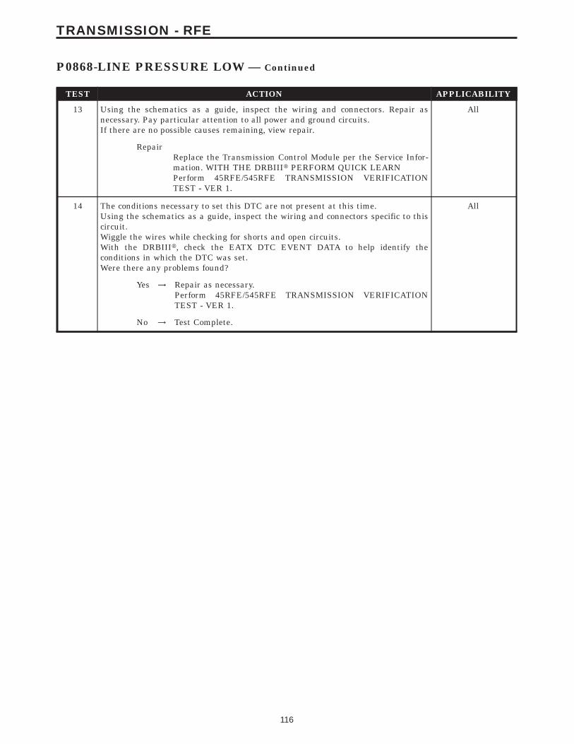
TEST ACTION APPLICABILITY
13 Using the schematics as a guide, inspect the wiring and connectors. Repair asnecessary. Pay particular attention to all power and ground circuits.If there are no possible causes remaining, view repair.
All
RepairReplace the Transmission Control Module per the Service Infor-mation. WITH THE DRBIIIt PERFORM QUICK LEARNPerform 45RFE/545RFE TRANSMISSION VERIFICATIONTEST - VER 1.
14 The conditions necessary to set this DTC are not present at this time.Using the schematics as a guide, inspect the wiring and connectors specific to thiscircuit.Wiggle the wires while checking for shorts and open circuits.With the DRBIIIt, check the EATX DTC EVENT DATA to help identify theconditions in which the DTC was set.Were there any problems found?
All
Yes → Repair as necessary.Perform 45RFE/545RFE TRANSMISSION VERIFICATIONTEST - VER 1.
No → Test Complete.
116
TRANSMISSION - RFE
P0868-LINE PRESSURE LOW — Continued
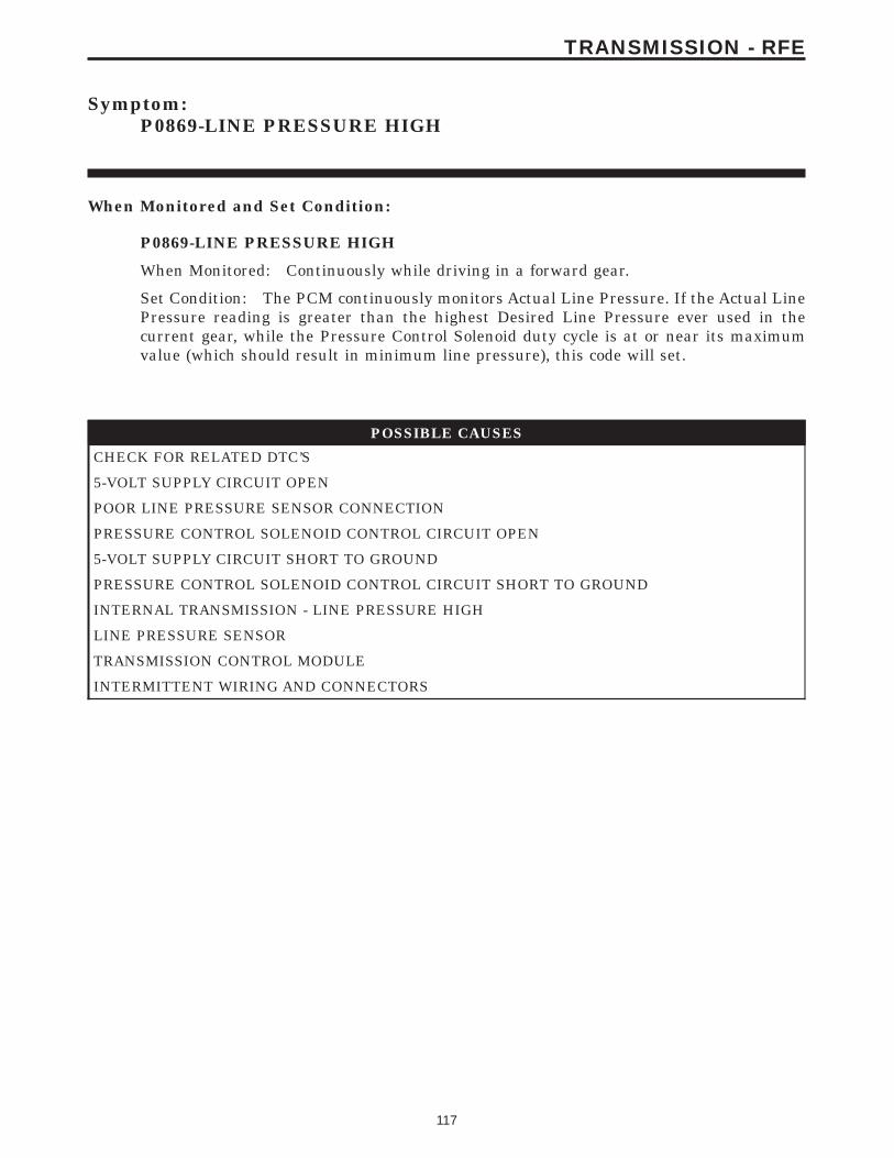
Symptom:P0869-LINE PRESSURE HIGH
When Monitored and Set Condition:
P0869-LINE PRESSURE HIGH
When Monitored: Continuously while driving in a forward gear.
Set Condition: The PCM continuously monitors Actual Line Pressure. If the Actual LinePressure reading is greater than the highest Desired Line Pressure ever used in thecurrent gear, while the Pressure Control Solenoid duty cycle is at or near its maximumvalue (which should result in minimum line pressure), this code will set.
POSSIBLE CAUSES
CHECK FOR RELATED DTC’S
5-VOLT SUPPLY CIRCUIT OPEN
POOR LINE PRESSURE SENSOR CONNECTION
PRESSURE CONTROL SOLENOID CONTROL CIRCUIT OPEN
5-VOLT SUPPLY CIRCUIT SHORT TO GROUND
PRESSURE CONTROL SOLENOID CONTROL CIRCUIT SHORT TO GROUND
INTERNAL TRANSMISSION - LINE PRESSURE HIGH
LINE PRESSURE SENSOR
TRANSMISSION CONTROL MODULE
INTERMITTENT WIRING AND CONNECTORS
117
TRANSMISSION - RFE
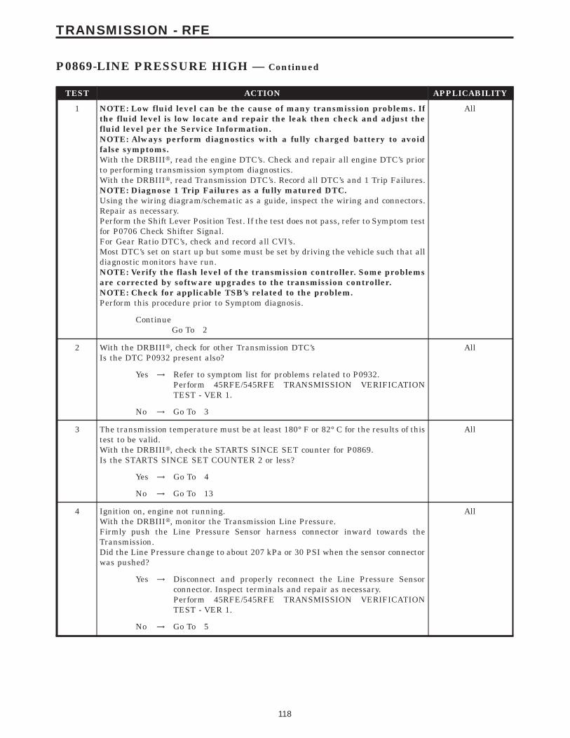
TEST ACTION APPLICABILITY
1 NOTE: Low fluid level can be the cause of many transmission problems. Ifthe fluid level is low locate and repair the leak then check and adjust thefluid level per the Service Information.NOTE: Always perform diagnostics with a fully charged battery to avoidfalse symptoms.With the DRBIIIt, read the engine DTC’s. Check and repair all engine DTC’s priorto performing transmission symptom diagnostics.With the DRBIIIt, read Transmission DTC’s. Record all DTC’s and 1 Trip Failures.NOTE: Diagnose 1 Trip Failures as a fully matured DTC.Using the wiring diagram/schematic as a guide, inspect the wiring and connectors.Repair as necessary.Perform the Shift Lever Position Test. If the test does not pass, refer to Symptom testfor P0706 Check Shifter Signal.For Gear Ratio DTC’s, check and record all CVI’s.Most DTC’s set on start up but some must be set by driving the vehicle such that alldiagnostic monitors have run.NOTE: Verify the flash level of the transmission controller. Some problemsare corrected by software upgrades to the transmission controller.NOTE: Check for applicable TSB’s related to the problem.Perform this procedure prior to Symptom diagnosis.
All
ContinueGo To 2
2 With the DRBIIIt, check for other Transmission DTC’sIs the DTC P0932 present also?
All
Yes → Refer to symptom list for problems related to P0932.Perform 45RFE/545RFE TRANSMISSION VERIFICATIONTEST - VER 1.
No → Go To 3
3 The transmission temperature must be at least 180° F or 82° C for the results of thistest to be valid.With the DRBIIIt, check the STARTS SINCE SET counter for P0869.Is the STARTS SINCE SET COUNTER 2 or less?
All
Yes → Go To 4
No → Go To 13
4 Ignition on, engine not running.With the DRBIIIt, monitor the Transmission Line Pressure.Firmly push the Line Pressure Sensor harness connector inward towards theTransmission.Did the Line Pressure change to about 207 kPa or 30 PSI when the sensor connectorwas pushed?
All
Yes → Disconnect and properly reconnect the Line Pressure Sensorconnector. Inspect terminals and repair as necessary.Perform 45RFE/545RFE TRANSMISSION VERIFICATIONTEST - VER 1.
No → Go To 5
118
TRANSMISSION - RFE
P0869-LINE PRESSURE HIGH — Continued

TEST ACTION APPLICABILITY
5 Turn the ignition off to the lock position.Remove the Starter Relay.NOTE: Failure to remove the Starter Relay can cause a TCM - No Responsecondition.Install the Transmission Simulator Miller tool# 8333.With the Transmission Simulator select the 9OFF9 position on the 9Input/OutputSpeed9 switch.NOTE: Check connectors - Clean/repair as necessary.Ignition on, engine not running.With the DRBIIIt, monitor the Line Pressure during the following step.Using the Transmission Simulator, set the rotary knob to each of the 3 line pressurepositions.NOTE: All three DRBIIIt Line Pressure readings should be steady and ± 2.0PSI of the reading specified on the Transmission Simulator.Did the Line Pressure remain steady in all three positions?
All
Yes → Go To 6
No → Go To 8
6 Turn the ignition off to the lock position.Install the Line Pressure Adaptor, Miller tool# 8259, and the Pressure Gauge, Millertool# C-3293, 0 to 2000 kPa or 0 to 300 PSI.Start the engine in park.With the DRBIIIt, monitor the Line Pressure.Monitor the reading on the Pressure Gauge, Miller tool# C-3293.Compare the Line Pressure reading between the DRBIIIt and the Pressure Gauge.Is the Pressure Gauge reading within 34 kPa or 5 PSI of the DRBIIIt reading?
All
Yes → Go To 7
No → Replace the Line Pressure Sensor per the Service Information.Perform 45RFE/545RFE TRANSMISSION VERIFICATIONTEST - VER 1.
7 If there are no possible causes remaining, view repair. All
RepairRepair internal transmission per the Service Information. Inspectthe Transmission Oil Pump per the Service Information andreplace if necessary. If no problem is found, replace the Transmis-sion Solenoid/TRS Assembly - stuck Pressure Control Solenoid.Perform 45RFE/545RFE TRANSMISSION VERIFICATIONTEST - VER 1.
8 Turn the ignition off to the lock position.Disconnect the Transmission Control Module harness connector.Disconnect the Line Pressure Sensor harness connector.Note: Check connectors - Clean/repair as necessary.Measure the resistance of the 5-volt Supply circuit from the Line Pressure Sensorharness connector to the Transmission Control Module harness connector.Is the resistance above 5.0 ohms?
All
Yes → Repair the 5-volt Supply circuit for an open.Perform 45RFE/545RFE TRANSMISSION VERIFICATIONTEST - VER 1.
No → Go To 9
119
TRANSMISSION - RFE
P0869-LINE PRESSURE HIGH — Continued

TEST ACTION APPLICABILITY
9 Turn the ignition off to the lock position.Disconnect the TCM harness connector.Disconnect the Line Pressure Sensor harness connector.Note: Check connectors - Clean/repair as necessary.Measure the resistance between ground and the 5-volt Supply circuit.Is the resistance below 5.0 ohms?
All
Yes → Repair the 5-volt Supply circuit for a short to ground.Perform 45RFE/545RFE TRANSMISSION VERIFICATIONTEST - VER 1.
No → Go To 10
10 Turn the ignition off to the lock position.Disconnect the Transmission Control Module harness connector.Disconnect the Transmission Solenoid /TRS harness connectorNote: Check connectors - Clean/repair as necessary.Measure the resistance of the Pressure Control Solenoid Control circuit from theTransmission Control Module harness connector to the Solenoid/TRS harness con-nector.Is the resistance above 5.0 ohms?
All
Yes → Repair the Pressure Control Solenoid Control circuit for an open.Perform 45RFE/545RFE TRANSMISSION VERIFICATIONTEST - VER 1.
No → Go To 11
11 Turn the ignition off to the lock position.Disconnect the Transmission Control Module harness connector.Disconnect the Transmission Solenoid/TRS harness connector.Note: Check connectors - Clean/repair as necessary.Measure the resistance between ground and the Pressure Control Solenoid Controlcircuit.Is the resistance below 5.0 ohms?
All
Yes → Repair the Pressure Control Solenoid Control circuit for a short toground.Perform 45RFE/545RFE TRANSMISSION VERIFICATIONTEST - VER 1.
No → Go To 12
12 Using the schematics as a guide, inspect the wiring and connectors. Repair asnecessary. Pay particular attention to all power and ground circuits.If there are no possible causes remaining, view repair.
All
RepairReplace the Transmission Control Module per the Service Infor-mation. WITH THE DRBIIIt PERFORM QUICK LEARNPerform 45RFE/545RFE TRANSMISSION VERIFICATIONTEST - VER 1.
120
TRANSMISSION - RFE
P0869-LINE PRESSURE HIGH — Continued

TEST ACTION APPLICABILITY
13 The conditions necessary to set this DTC are not present at this time.Using the schematics as a guide, inspect the wiring and connectors specific to thiscircuit.Wiggle the wires while checking for shorts and open circuits.With the DRBIIIt, check the EATX DTC EVENT DATA to help identify theconditions in which the DTC was set.Were there any problems found?
All
Yes → Repair as necessary.Perform 45RFE/545RFE TRANSMISSION VERIFICATIONTEST - VER 1.
No → Test Complete.
121
TRANSMISSION - RFE
P0869-LINE PRESSURE HIGH — Continued

Symptom:P0870-OD HYDRAULIC PRESSURE TEST FAILURE
When Monitored and Set Condition:
P0870-OD HYDRAULIC PRESSURE TEST FAILURE
When Monitored: In any forward gear with engine speed above 1000 RPM shortly aftera shift and every minute thereafter.
Set Condition: After a shift into a forward gear, with engine speed above 1000 RPM, theTCM momentarily turns on element pressure to the clutch circuits that don’t havepressure to identify the correct pressure switch closes. If the pressure switch does not close2 times the DTC sets.
POSSIBLE CAUSES
RELATED LINE PRESSURE DTC’S PRESENT
5-VOLT SUPPLY CIRCUIT OPEN
OD PRESSURE SWITCH SENSE CIRCUIT OPEN
POOR LINE PRESSURE SENSOR CONNECTION
TRANSMISSION CONTROL RELAY OUTPUT CIRCUIT OPEN
5-VOLT SUPPLY CIRCUIT SHORT TO GROUND
OD PRESSURE SWITCH SENSE CIRCUIT SHORT TO GROUND
OD PRESSURE SWITCH SENSE CIRCUIT SHORT TO VOLTAGE
EXCESSIVE DEBRIS IN OIL PAN
LINE PRESSURE SENSOR
TRANSMISSION SOLENOID/TRS ASSEMBLY
INTERNAL TRANSMISSION
TRANSMISSION CONTROL MODULE
INTERMITTENT WIRING AND CONNECTORS
122
TRANSMISSION - RFE
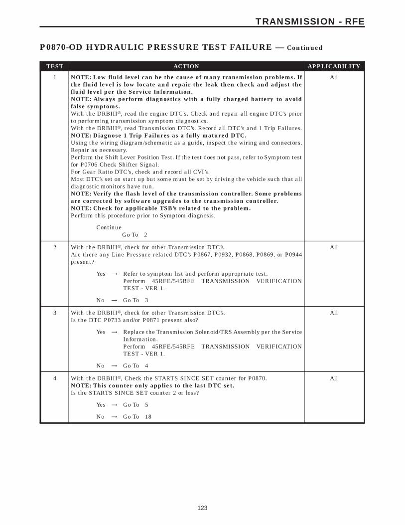
TEST ACTION APPLICABILITY
1 NOTE: Low fluid level can be the cause of many transmission problems. Ifthe fluid level is low locate and repair the leak then check and adjust thefluid level per the Service Information.NOTE: Always perform diagnostics with a fully charged battery to avoidfalse symptoms.With the DRBIIIt, read the engine DTC’s. Check and repair all engine DTC’s priorto performing transmission symptom diagnostics.With the DRBIIIt, read Transmission DTC’s. Record all DTC’s and 1 Trip Failures.NOTE: Diagnose 1 Trip Failures as a fully matured DTC.Using the wiring diagram/schematic as a guide, inspect the wiring and connectors.Repair as necessary.Perform the Shift Lever Position Test. If the test does not pass, refer to Symptom testfor P0706 Check Shifter Signal.For Gear Ratio DTC’s, check and record all CVI’s.Most DTC’s set on start up but some must be set by driving the vehicle such that alldiagnostic monitors have run.NOTE: Verify the flash level of the transmission controller. Some problemsare corrected by software upgrades to the transmission controller.NOTE: Check for applicable TSB’s related to the problem.Perform this procedure prior to Symptom diagnosis.
All
ContinueGo To 2
2 With the DRBIIIt, check for other Transmission DTC’s.Are there any Line Pressure related DTC’s P0867, P0932, P0868, P0869, or P0944present?
All
Yes → Refer to symptom list and perform appropriate test.Perform 45RFE/545RFE TRANSMISSION VERIFICATIONTEST - VER 1.
No → Go To 3
3 With the DRBIIIt, check for other Transmission DTC’s.Is the DTC P0733 and/or P0871 present also?
All
Yes → Replace the Transmission Solenoid/TRS Assembly per the ServiceInformation.Perform 45RFE/545RFE TRANSMISSION VERIFICATIONTEST - VER 1.
No → Go To 4
4 With the DRBIIIt, Check the STARTS SINCE SET counter for P0870.NOTE: This counter only applies to the last DTC set.Is the STARTS SINCE SET counter 2 or less?
All
Yes → Go To 5
No → Go To 18
123
TRANSMISSION - RFE
P0870-OD HYDRAULIC PRESSURE TEST FAILURE — Continued
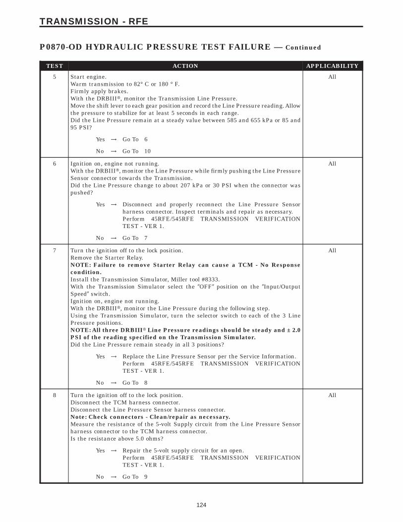
TEST ACTION APPLICABILITY
5 Start engine.Warm transmission to 82° C or 180 ° F.Firmly apply brakes.With the DRBIIIt, monitor the Transmission Line Pressure.Move the shift lever to each gear position and record the Line Pressure reading. Allowthe pressure to stabilize for at least 5 seconds in each range.Did the Line Pressure remain at a steady value between 585 and 655 kPa or 85 and95 PSI?
All
Yes → Go To 6
No → Go To 10
6 Ignition on, engine not running.With the DRBIIIt, monitor the Line Pressure while firmly pushing the Line PressureSensor connector towards the Transmission.Did the Line Pressure change to about 207 kPa or 30 PSI when the connector waspushed?
All
Yes → Disconnect and properly reconnect the Line Pressure Sensorharness connector. Inspect terminals and repair as necessary.Perform 45RFE/545RFE TRANSMISSION VERIFICATIONTEST - VER 1.
No → Go To 7
7 Turn the ignition off to the lock position.Remove the Starter Relay.NOTE: Failure to remove Starter Relay can cause a TCM - No Responsecondition.Install the Transmission Simulator, Miller tool #8333.With the Transmission Simulator select the 9OFF9 position on the 9Input/OutputSpeed9 switch.Ignition on, engine not running.With the DRBIIIt, monitor the Line Pressure during the following step.Using the Transmission Simulator, turn the selector switch to each of the 3 LinePressure positions.NOTE: All three DRBIIIt Line Pressure readings should be steady and ± 2.0PSI of the reading specified on the Transmission Simulator.Did the Line Pressure remain steady in all 3 positions?
All
Yes → Replace the Line Pressure Sensor per the Service Information.Perform 45RFE/545RFE TRANSMISSION VERIFICATIONTEST - VER 1.
No → Go To 8
8 Turn the ignition off to the lock position.Disconnect the TCM harness connector.Disconnect the Line Pressure Sensor harness connector.Note: Check connectors - Clean/repair as necessary.Measure the resistance of the 5-volt Supply circuit from the Line Pressure Sensorharness connector to the TCM harness connector.Is the resistance above 5.0 ohms?
All
Yes → Repair the 5-volt supply circuit for an open.Perform 45RFE/545RFE TRANSMISSION VERIFICATIONTEST - VER 1.
No → Go To 9
124
TRANSMISSION - RFE
P0870-OD HYDRAULIC PRESSURE TEST FAILURE — Continued
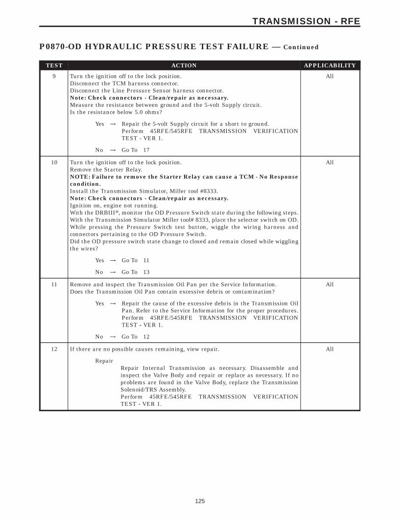
TEST ACTION APPLICABILITY
9 Turn the ignition off to the lock position.Disconnect the TCM harness connector.Disconnect the Line Pressure Sensor harness connector.Note: Check connectors - Clean/repair as necessary.Measure the resistance between ground and the 5-volt Supply circuit.Is the resistance below 5.0 ohms?
All
Yes → Repair the 5-volt Supply circuit for a short to ground.Perform 45RFE/545RFE TRANSMISSION VERIFICATIONTEST - VER 1.
No → Go To 17
10 Turn the ignition off to the lock position.Remove the Starter Relay.NOTE: Failure to remove the Starter Relay can cause a TCM - No Responsecondition.Install the Transmission Simulator, Miller tool #8333.Note: Check connectors - Clean/repair as necessary.Ignition on, engine not running.With the DRBIIIt, monitor the OD Pressure Switch state during the following steps.With the Transmission Simulator Miller tool# 8333, place the selector switch on OD.While pressing the Pressure Switch test button, wiggle the wiring harness andconnectors pertaining to the OD Pressure Switch.Did the OD pressure switch state change to closed and remain closed while wigglingthe wires?
All
Yes → Go To 11
No → Go To 13
11 Remove and inspect the Transmission Oil Pan per the Service Information.Does the Transmission Oil Pan contain excessive debris or contamination?
All
Yes → Repair the cause of the excessive debris in the Transmission OilPan. Refer to the Service Information for the proper procedures.Perform 45RFE/545RFE TRANSMISSION VERIFICATIONTEST - VER 1.
No → Go To 12
12 If there are no possible causes remaining, view repair. All
RepairRepair Internal Transmission as necessary. Disassemble andinspect the Valve Body and repair or replace as necessary. If noproblems are found in the Valve Body, replace the TransmissionSolenoid/TRS Assembly.Perform 45RFE/545RFE TRANSMISSION VERIFICATIONTEST - VER 1.
125
TRANSMISSION - RFE
P0870-OD HYDRAULIC PRESSURE TEST FAILURE — Continued
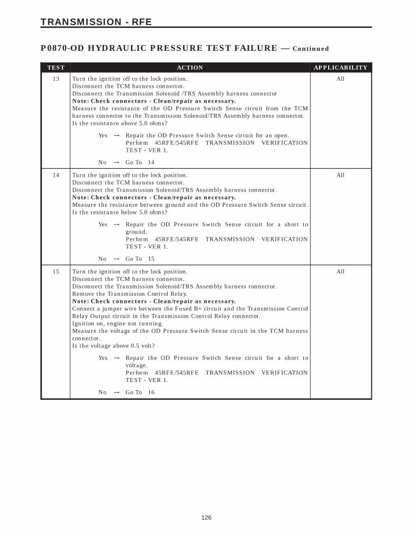
TEST ACTION APPLICABILITY
13 Turn the ignition off to the lock position.Disconnect the TCM harness connector.Disconnect the Transmission Solenoid /TRS Assembly harness connectorNote: Check connectors - Clean/repair as necessary.Measure the resistance of the OD Pressure Switch Sense circuit from the TCMharness connector to the Transmission Solenoid/TRS Assembly harness connector.Is the resistance above 5.0 ohms?
All
Yes → Repair the OD Pressure Switch Sense circuit for an open.Perform 45RFE/545RFE TRANSMISSION VERIFICATIONTEST - VER 1.
No → Go To 14
14 Turn the ignition off to the lock position.Disconnect the TCM harness connector.Disconnect the Transmission Solenoid/TRS Assembly harness connector.Note: Check connectors - Clean/repair as necessary.Measure the resistance between ground and the OD Pressure Switch Sense circuit.Is the resistance below 5.0 ohms?
All
Yes → Repair the OD Pressure Switch Sense circuit for a short toground.Perform 45RFE/545RFE TRANSMISSION VERIFICATIONTEST - VER 1.
No → Go To 15
15 Turn the ignition off to the lock position.Disconnect the TCM harness connector.Disconnect the Transmission Solenoid/TRS Assembly harness connector.Remove the Transmission Control Relay.Note: Check connectors - Clean/repair as necessary.Connect a jumper wire between the Fused B+ circuit and the Transmission ControlRelay Output circuit in the Transmission Control Relay connector.Ignition on, engine not running.Measure the voltage of the OD Pressure Switch Sense circuit in the TCM harnessconnector.Is the voltage above 0.5 volt?
All
Yes → Repair the OD Pressure Switch Sense circuit for a short tovoltage.Perform 45RFE/545RFE TRANSMISSION VERIFICATIONTEST - VER 1.
No → Go To 16
126
TRANSMISSION - RFE
P0870-OD HYDRAULIC PRESSURE TEST FAILURE — Continued

TEST ACTION APPLICABILITY
16 Turn the ignition off to the lock position.Disconnect the Transmission Solenoid/TRS Assembly harness connector.Remove the Transmission Control Relay.Connect a jumper wire between the Fused B(+) circuit and the Transmission ControlRelay Output circuit in the Transmission Control Relay connector.Ignition on, engine not running.Using a 12-volt test light connected to ground, check the Transmission Control RelayOutput circuit at the Transmission Solenoid/TRS Assembly harness connector.NOTE: The test light must illuminate brightly. Compare the brightness tothat of a direct connection to the battery.Does the test light illuminate brightly?
All
Yes → Go To 17
No → Repair the Transmission Control Relay Output circuit for anopen. If the fuse is open make sure to check for a short to ground.Perform 45RFE/545RFE TRANSMISSION VERIFICATIONTEST - VER 1.
17 Using the schematics as a guide, inspect the wiring and connectors. Repair asnecessary. Pay particular attention to all power and ground circuits.If there are no possible causes remaining, view repair.
All
RepairReplace the Transmission Control Module per the Service Infor-mation. WITH THE DRBIIIt PERFORM QUICK LEARNPerform 45RFE/545RFE TRANSMISSION VERIFICATIONTEST - VER 1.
18 The conditions necessary to set this DTC are not present at this time.Using the schematics as a guide, inspect the wiring and connectors specific to thiscircuit.Wiggle the wires while checking for shorts and open circuits.With the DRBIIIt, check the EATX DTC EVENT DATA to help identify theconditions in which the DTC was set.Were there any problems found?
All
Yes → Repair as necessary.Perform 45RFE/545RFE TRANSMISSION VERIFICATIONTEST - VER 1.
No → Test Complete.
127
TRANSMISSION - RFE
P0870-OD HYDRAULIC PRESSURE TEST FAILURE — Continued
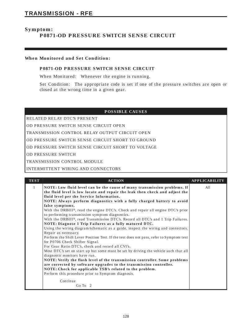
Symptom:P0871-OD PRESSURE SWITCH SENSE CIRCUIT
When Monitored and Set Condition:
P0871-OD PRESSURE SWITCH SENSE CIRCUIT
When Monitored: Whenever the engine is running.
Set Condition: The appropriate code is set if one of the pressure switches are open orclosed at the wrong time in a given gear.
POSSIBLE CAUSES
RELATED RELAY DTC’S PRESENT
OD PRESSURE SWITCH SENSE CIRCUIT OPEN
TRANSMISSION CONTROL RELAY OUTPUT CIRCUIT OPEN
OD PRESSURE SWITCH SENSE CIRCUIT SHORT TO GROUND
OD PRESSURE SWITCH SENSE CIRCUIT SHORT TO VOLTAGE
OD PRESSURE SWITCH
TRANSMISSION CONTROL MODULE
INTERMITTENT WIRING AND CONNECTORS
TEST ACTION APPLICABILITY
1 NOTE: Low fluid level can be the cause of many transmission problems. Ifthe fluid level is low locate and repair the leak then check and adjust thefluid level per the Service Information.NOTE: Always perform diagnostics with a fully charged battery to avoidfalse symptoms.With the DRBIIIt, read the engine DTC’s. Check and repair all engine DTC’s priorto performing transmission symptom diagnostics.With the DRBIIIt, read Transmission DTC’s. Record all DTC’s and 1 Trip Failures.NOTE: Diagnose 1 Trip Failures as a fully matured DTC.Using the wiring diagram/schematic as a guide, inspect the wiring and connectors.Repair as necessary.Perform the Shift Lever Position Test. If the test does not pass, refer to Symptom testfor P0706 Check Shifter Signal.For Gear Ratio DTC’s, check and record all CVI’s.Most DTC’s set on start up but some must be set by driving the vehicle such that alldiagnostic monitors have run.NOTE: Verify the flash level of the transmission controller. Some problemsare corrected by software upgrades to the transmission controller.NOTE: Check for applicable TSB’s related to the problem.Perform this procedure prior to Symptom diagnosis.
All
ContinueGo To 2
128
TRANSMISSION - RFE

TEST ACTION APPLICABILITY
2 With the DRBIIIt, check for other transmission DTC’s.Are there any Transmission Control Relay related DTC’s, P0890, P0891, or P0888present?
All
Yes → Refer to symptom list and perform test for Transmission ControlRelay related DTCs.Perform 45RFE/545RFE TRANSMISSION VERIFICATIONTEST - VER 1.
No → Go To 3
3 Ignition on, engine not running.With the DRBIIIt, Check the STARTS SINCE SET counter for P0871.NOTE: This counter only applies to the last DTC set.Is the STARTS SINCE SET counter 2 or less?
All
Yes → Go To 4
No → Go To 11
4 Turn the ignition off to the lock position.Remove the Starter Relay.NOTE: Failure to remove the Starter Relay can cause a TCM - No Responsecondition.Install Transmission Simulator, Miller tool #8333.Note: Check connectors - Clean/repair as necessary.Ignition on, engine not running.With the Transmission Simulator, turn the Pressure Switch selector switch to OD.With the DRBIIIt, monitor the OD Pressure Switch state while pressing thePressure Switch Test button on the Transmission Simulator.Did the state of the OD Pressure Switch change while pressing the Pressure SwitchTest button?
All
Yes → Go To 5
No → Go To 6
5 If there are no possible causes remaining, view repair. All
RepairReplace the Transmission Solenoid/TRS Assembly per the ServiceInformation.Perform 45RFE/545RFE TRANSMISSION VERIFICATIONTEST - VER 1.
129
TRANSMISSION - RFE
P0871-OD PRESSURE SWITCH SENSE CIRCUIT — Continued
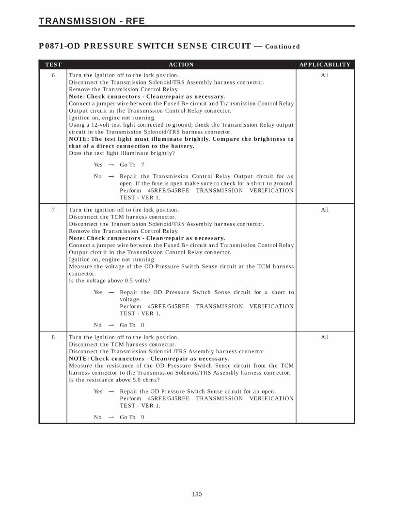
TEST ACTION APPLICABILITY
6 Turn the ignition off to the lock position.Disconnect the Transmission Solenoid/TRS Assembly harness connector.Remove the Transmission Control Relay.Note: Check connectors - Clean/repair as necessary.Connect a jumper wire between the Fused B+ circuit and Transmission Control RelayOutput circuit in the Transmission Control Relay connector.Ignition on, engine not running.Using a 12-volt test light connected to ground, check the Transmission Relay outputcircuit in the Transmission Solenoid/TRS harness connector.NOTE: The test light must illuminate brightly. Compare the brightness tothat of a direct connection to the battery.Does the test light illuminate brightly?
All
Yes → Go To 7
No → Repair the Transmission Control Relay Output circuit for anopen. If the fuse is open make sure to check for a short to ground.Perform 45RFE/545RFE TRANSMISSION VERIFICATIONTEST - VER 1.
7 Turn the ignition off to the lock position.Disconnect the TCM harness connector.Disconnect the Transmission Solenoid/TRS Assembly harness connector.Remove the Transmission Control Relay.Note: Check connectors - Clean/repair as necessary.Connect a jumper wire between the Fused B+ circuit and Transmission Control RelayOutput circuit in the Transmission Control Relay connector.Ignition on, engine not running.Measure the voltage of the OD Pressure Switch Sense circuit at the TCM harnessconnector.Is the voltage above 0.5 volts?
All
Yes → Repair the OD Pressure Switch Sense circuit for a short tovoltage.Perform 45RFE/545RFE TRANSMISSION VERIFICATIONTEST - VER 1.
No → Go To 8
8 Turn the ignition off to the lock position.Disconnect the TCM harness connector.Disconnect the Transmission Solenoid /TRS Assembly harness connectorNOTE: Check connectors - Clean/repair as necessary.Measure the resistance of the OD Pressure Switch Sense circuit from the TCMharness connector to the Transmission Solenoid/TRS Assembly harness connector.Is the resistance above 5.0 ohms?
All
Yes → Repair the OD Pressure Switch Sense circuit for an open.Perform 45RFE/545RFE TRANSMISSION VERIFICATIONTEST - VER 1.
No → Go To 9
130
TRANSMISSION - RFE
P0871-OD PRESSURE SWITCH SENSE CIRCUIT — Continued
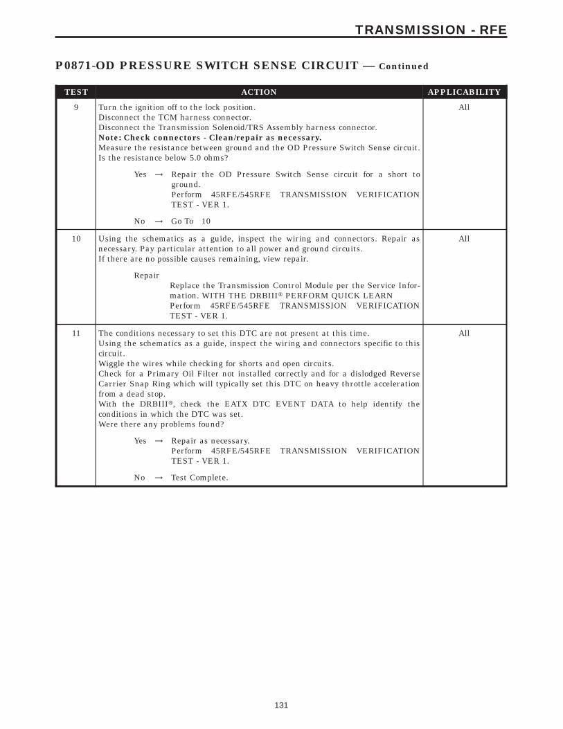
TEST ACTION APPLICABILITY
9 Turn the ignition off to the lock position.Disconnect the TCM harness connector.Disconnect the Transmission Solenoid/TRS Assembly harness connector.Note: Check connectors - Clean/repair as necessary.Measure the resistance between ground and the OD Pressure Switch Sense circuit.Is the resistance below 5.0 ohms?
All
Yes → Repair the OD Pressure Switch Sense circuit for a short toground.Perform 45RFE/545RFE TRANSMISSION VERIFICATIONTEST - VER 1.
No → Go To 10
10 Using the schematics as a guide, inspect the wiring and connectors. Repair asnecessary. Pay particular attention to all power and ground circuits.If there are no possible causes remaining, view repair.
All
RepairReplace the Transmission Control Module per the Service Infor-mation. WITH THE DRBIIIt PERFORM QUICK LEARNPerform 45RFE/545RFE TRANSMISSION VERIFICATIONTEST - VER 1.
11 The conditions necessary to set this DTC are not present at this time.Using the schematics as a guide, inspect the wiring and connectors specific to thiscircuit.Wiggle the wires while checking for shorts and open circuits.Check for a Primary Oil Filter not installed correctly and for a dislodged ReverseCarrier Snap Ring which will typically set this DTC on heavy throttle accelerationfrom a dead stop.With the DRBIIIt, check the EATX DTC EVENT DATA to help identify theconditions in which the DTC was set.Were there any problems found?
All
Yes → Repair as necessary.Perform 45RFE/545RFE TRANSMISSION VERIFICATIONTEST - VER 1.
No → Test Complete.
131
TRANSMISSION - RFE
P0871-OD PRESSURE SWITCH SENSE CIRCUIT — Continued
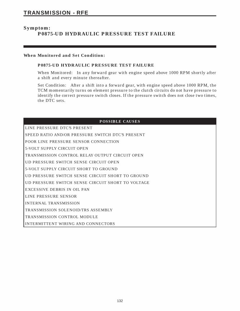
Symptom:P0875-UD HYDRAULIC PRESSURE TEST FAILURE
When Monitored and Set Condition:
P0875-UD HYDRAULIC PRESSURE TEST FAILURE
When Monitored: In any forward gear with engine speed above 1000 RPM shortly aftera shift and every minute thereafter.
Set Condition: After a shift into a forward gear, with engine speed above 1000 RPM, theTCM momentarily turns on element pressure to the clutch circuits do not have pressure toidentify the correct pressure switch closes. If the pressure switch does not close two times,the DTC sets.
POSSIBLE CAUSES
LINE PRESSURE DTC’S PRESENT
SPEED RATIO AND/OR PRESSURE SWITCH DTC’S PRESENT
POOR LINE PRESSURE SENSOR CONNECTION
5-VOLT SUPPLY CIRCUIT OPEN
TRANSMISSION CONTROL RELAY OUTPUT CIRCUIT OPEN
UD PRESSURE SWITCH SENSE CIRCUIT OPEN
5-VOLT SUPPLY CIRCUIT SHORT TO GROUND
UD PRESSURE SWITCH SENSE CIRCUIT SHORT TO GROUND
UD PRESSURE SWITCH SENSE CIRCUIT SHORT TO VOLTAGE
EXCESSIVE DEBRIS IN OIL PAN
LINE PRESSURE SENSOR
INTERNAL TRANSMISSION
TRANSMISSION SOLENOID/TRS ASSEMBLY
TRANSMISSION CONTROL MODULE
INTERMITTENT WIRING AND CONNECTORS
132
TRANSMISSION - RFE
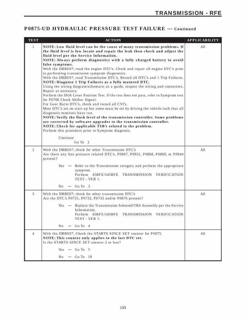
TEST ACTION APPLICABILITY
1 NOTE: Low fluid level can be the cause of many transmission problems. Ifthe fluid level is low locate and repair the leak then check and adjust thefluid level per the Service Information.NOTE: Always perform diagnostics with a fully charged battery to avoidfalse symptoms.With the DRBIIIt, read the engine DTC’s. Check and repair all engine DTC’s priorto performing transmission symptom diagnostics.With the DRBIIIt, read Transmission DTC’s. Record all DTC’s and 1 Trip Failures.NOTE: Diagnose 1 Trip Failures as a fully matured DTC.Using the wiring diagram/schematic as a guide, inspect the wiring and connectors.Repair as necessary.Perform the Shift Lever Position Test. If the test does not pass, refer to Symptom testfor P0706 Check Shifter Signal.For Gear Ratio DTC’s, check and record all CVI’s.Most DTC’s set on start up but some must be set by driving the vehicle such that alldiagnostic monitors have run.NOTE: Verify the flash level of the transmission controller. Some problemsare corrected by software upgrades to the transmission controller.NOTE: Check for applicable TSB’s related to the problem.Perform this procedure prior to Symptom diagnosis.
All
ContinueGo To 2
2 With the DRBIIIt, check for other Transmission DTC’sAre there any line pressure related DTC’s, P0867, P0932, P0868, P0869, or P0944present?
All
Yes → Refer to the Transmission category and perform the appropriatesymptom.Perform 45RFE/545RFE TRANSMISSION VERIFICATIONTEST - VER 1.
No → Go To 3
3 With the DRBIIIt, check for other transmission DTC’sAre the DTC’s P0731, P0732, P0733 and/or P0876 present?
All
Yes → Replace the Transmission Solenoid/TRS Assembly per the ServiceInformation.Perform 45RFE/545RFE TRANSMISSION VERIFICATIONTEST - VER 1.
No → Go To 4
4 With the DRBIIIt, Check the STARTS SINCE SET counter for P0875.NOTE: This counter only applies to the last DTC set.Is the STARTS SINCE SET counter 2 or less?
All
Yes → Go To 5
No → Go To 18
133
TRANSMISSION - RFE
P0875-UD HYDRAULIC PRESSURE TEST FAILURE — Continued
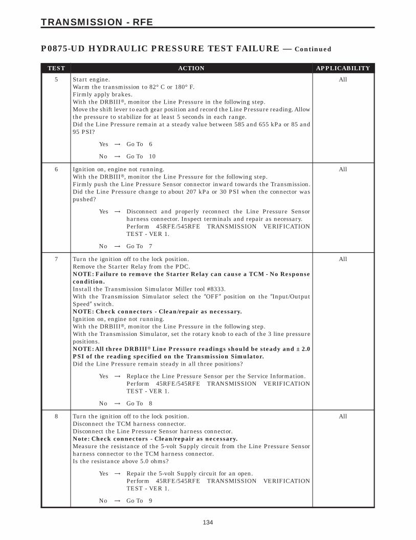
TEST ACTION APPLICABILITY
5 Start engine.Warm the transmission to 82° C or 180° F.Firmly apply brakes.With the DRBIIIt, monitor the Line Pressure in the following step.Move the shift lever to each gear position and record the Line Pressure reading. Allowthe pressure to stabilize for at least 5 seconds in each range.Did the Line Pressure remain at a steady value between 585 and 655 kPa or 85 and95 PSI?
All
Yes → Go To 6
No → Go To 10
6 Ignition on, engine not running.With the DRBIIIt, monitor the Line Pressure for the following step.Firmly push the Line Pressure Sensor connector inward towards the Transmission.Did the Line Pressure change to about 207 kPa or 30 PSI when the connector waspushed?
All
Yes → Disconnect and properly reconnect the Line Pressure Sensorharness connector. Inspect terminals and repair as necessary.Perform 45RFE/545RFE TRANSMISSION VERIFICATIONTEST - VER 1.
No → Go To 7
7 Turn the ignition off to the lock position.Remove the Starter Relay from the PDC.NOTE: Failure to remove the Starter Relay can cause a TCM - No Responsecondition.Install the Transmission Simulator Miller tool #8333.With the Transmission Simulator select the 9OFF9 position on the 9Input/OutputSpeed9 switch.NOTE: Check connectors - Clean/repair as necessary.Ignition on, engine not running.With the DRBIIIt, monitor the Line Pressure in the following step.With the Transmission Simulator, set the rotary knob to each of the 3 line pressurepositions.NOTE: All three DRBIIIt Line Pressure readings should be steady and ± 2.0PSI of the reading specified on the Transmission Simulator.Did the Line Pressure remain steady in all three positions?
All
Yes → Replace the Line Pressure Sensor per the Service Information.Perform 45RFE/545RFE TRANSMISSION VERIFICATIONTEST - VER 1.
No → Go To 8
8 Turn the ignition off to the lock position.Disconnect the TCM harness connector.Disconnect the Line Pressure Sensor harness connector.Note: Check connectors - Clean/repair as necessary.Measure the resistance of the 5-volt Supply circuit from the Line Pressure Sensorharness connector to the TCM harness connector.Is the resistance above 5.0 ohms?
All
Yes → Repair the 5-volt Supply circuit for an open.Perform 45RFE/545RFE TRANSMISSION VERIFICATIONTEST - VER 1.
No → Go To 9
134
TRANSMISSION - RFE
P0875-UD HYDRAULIC PRESSURE TEST FAILURE — Continued

TEST ACTION APPLICABILITY
9 Turn the ignition off to the lock position.Disconnect the TCM harness connector.Disconnect the Line Pressure Sensor harness connector.Note: Check connectors - Clean/repair as necessary.Measure the resistance between ground and the 5-volt Supply circuit.Is the resistance Below 5.0 ohms?
All
Yes → Repair the 5-volt Supply circuit for a short to ground.Perform 45RFE/545RFE TRANSMISSION VERIFICATIONTEST - VER 1.
No → Go To 17
10 Turn the ignition off to the lock position.Remove the Starter Relay.NOTE: Failure to remove the Starter Relay can cause a TCM - No Responsecondition.Install the Transmission Simulator, Miller tool #8333.Note: Check connectors - Clean/repair as necessary.Ignition on, engine not running.With the DRBIIIt, monitor the UD Pressure Switch state.With the Transmission Simulator, turn the selector switch on UD.While pressing and holding the Pressure Switch test button, wiggle the wiringharness and connectors pertaining to the UD Pressure Switch.Did the UD Pressure Switch state change to closed and remain closed while wigglingthe wires?
All
Yes → Go To 11
No → Go To 13
11 Remove and inspect Transmission Oil Pan per the Service Information.Does it contain excessive debris or contamination?
All
Yes → Repair the cause of the excessive debris in the Transmission OilPan. Refer to the Service Information for the proper procedures.Perform 45RFE/545RFE TRANSMISSION VERIFICATIONTEST - VER 1.
No → Go To 12
12 If there are no possible causes remaining, view repair. All
RepairRepair Internal Transmission as necessary. Disassemble andinspect the Valve Body and repair or replace as necessary. If noproblems are found in the Valve Body, replace the TransmissionSolenoid/TRS Assembly.Perform 45RFE/545RFE TRANSMISSION VERIFICATIONTEST - VER 1.
135
TRANSMISSION - RFE
P0875-UD HYDRAULIC PRESSURE TEST FAILURE — Continued
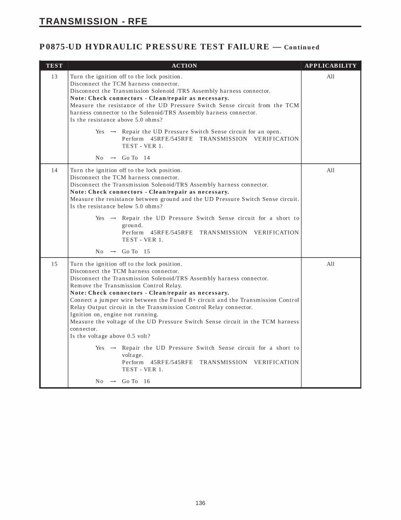
TEST ACTION APPLICABILITY
13 Turn the ignition off to the lock position.Disconnect the TCM harness connector.Disconnect the Transmission Solenoid /TRS Assembly harness connector.Note: Check connectors - Clean/repair as necessary.Measure the resistance of the UD Pressure Switch Sense circuit from the TCMharness connector to the Solenoid/TRS Assembly harness connector.Is the resistance above 5.0 ohms?
All
Yes → Repair the UD Pressure Switch Sense circuit for an open.Perform 45RFE/545RFE TRANSMISSION VERIFICATIONTEST - VER 1.
No → Go To 14
14 Turn the ignition off to the lock position.Disconnect the TCM harness connector.Disconnect the Transmission Solenoid/TRS Assembly harness connector.Note: Check connectors - Clean/repair as necessary.Measure the resistance between ground and the UD Pressure Switch Sense circuit.Is the resistance below 5.0 ohms?
All
Yes → Repair the UD Pressure Switch Sense circuit for a short toground.Perform 45RFE/545RFE TRANSMISSION VERIFICATIONTEST - VER 1.
No → Go To 15
15 Turn the ignition off to the lock position.Disconnect the TCM harness connector.Disconnect the Transmission Solenoid/TRS Assembly harness connector.Remove the Transmission Control Relay.Note: Check connectors - Clean/repair as necessary.Connect a jumper wire between the Fused B+ circuit and the Transmission ControlRelay Output circuit in the Transmission Control Relay connector.Ignition on, engine not running.Measure the voltage of the UD Pressure Switch Sense circuit in the TCM harnessconnector.Is the voltage above 0.5 volt?
All
Yes → Repair the UD Pressure Switch Sense circuit for a short tovoltage.Perform 45RFE/545RFE TRANSMISSION VERIFICATIONTEST - VER 1.
No → Go To 16
136
TRANSMISSION - RFE
P0875-UD HYDRAULIC PRESSURE TEST FAILURE — Continued
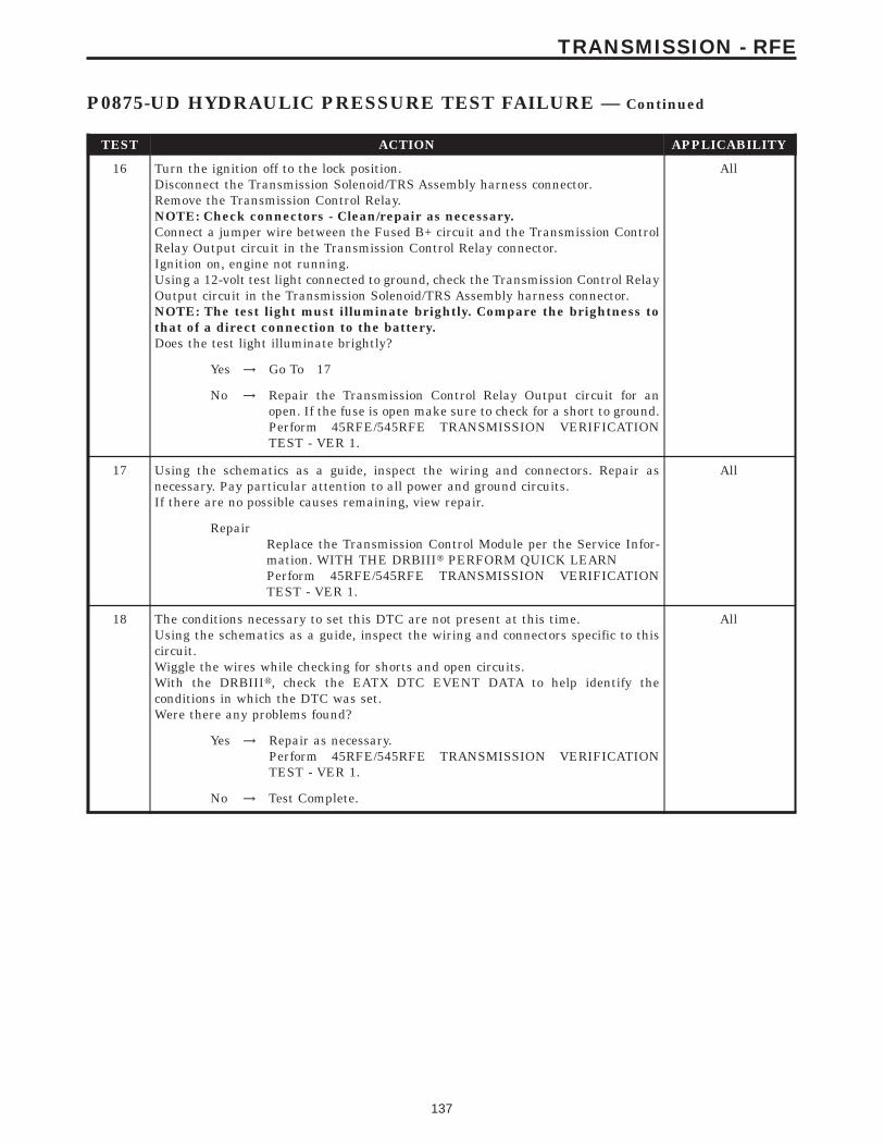
TEST ACTION APPLICABILITY
16 Turn the ignition off to the lock position.Disconnect the Transmission Solenoid/TRS Assembly harness connector.Remove the Transmission Control Relay.NOTE: Check connectors - Clean/repair as necessary.Connect a jumper wire between the Fused B+ circuit and the Transmission ControlRelay Output circuit in the Transmission Control Relay connector.Ignition on, engine not running.Using a 12-volt test light connected to ground, check the Transmission Control RelayOutput circuit in the Transmission Solenoid/TRS Assembly harness connector.NOTE: The test light must illuminate brightly. Compare the brightness tothat of a direct connection to the battery.Does the test light illuminate brightly?
All
Yes → Go To 17
No → Repair the Transmission Control Relay Output circuit for anopen. If the fuse is open make sure to check for a short to ground.Perform 45RFE/545RFE TRANSMISSION VERIFICATIONTEST - VER 1.
17 Using the schematics as a guide, inspect the wiring and connectors. Repair asnecessary. Pay particular attention to all power and ground circuits.If there are no possible causes remaining, view repair.
All
RepairReplace the Transmission Control Module per the Service Infor-mation. WITH THE DRBIIIt PERFORM QUICK LEARNPerform 45RFE/545RFE TRANSMISSION VERIFICATIONTEST - VER 1.
18 The conditions necessary to set this DTC are not present at this time.Using the schematics as a guide, inspect the wiring and connectors specific to thiscircuit.Wiggle the wires while checking for shorts and open circuits.With the DRBIIIt, check the EATX DTC EVENT DATA to help identify theconditions in which the DTC was set.Were there any problems found?
All
Yes → Repair as necessary.Perform 45RFE/545RFE TRANSMISSION VERIFICATIONTEST - VER 1.
No → Test Complete.
137
TRANSMISSION - RFE
P0875-UD HYDRAULIC PRESSURE TEST FAILURE — Continued

Symptom:P0876-UD PRESSURE SWITCH SENSE CIRCUIT
When Monitored and Set Condition:
P0876-UD PRESSURE SWITCH SENSE CIRCUIT
When Monitored: Whenever the engine is running.
Set Condition: This DTC is set if the UD pressure switch is in the wrong state for thecurrent gear. For example, this code would be set if the UD pressure switch remained offwhile the transmission was in second gear.
POSSIBLE CAUSES
RELAY DTC’S PRESENT
TRANSMISSION CONTROL RELAY OUTPUT CIRCUIT OPEN
UD PRESSURE SWITCH SENSE CIRCUIT OPEN
UD PRESSURE SWITCH CIRCUIT SHORT TO GROUND
UD PRESSURE SWITCH SENSE CIRCUIT SHORT TO VOLTAGE
UD PRESSURE SWITCH
TRANSMISSION CONTROL MODULE
INTERMITTENT WIRING AND CONNECTORS
TEST ACTION APPLICABILITY
1 NOTE: Low fluid level can be the cause of many transmission problems. Ifthe fluid level is low locate and repair the leak then check and adjust thefluid level per the Service Information.NOTE: Always perform diagnostics with a fully charged battery to avoidfalse symptoms.With the DRBIIIt, read the engine DTC’s. Check and repair all engine DTC’s priorto performing transmission symptom diagnostics.With the DRBIIIt, read Transmission DTC’s. Record all DTC’s and 1 Trip Failures.NOTE: Diagnose 1 Trip Failures as a fully matured DTC.Using the wiring diagram/schematic as a guide, inspect the wiring and connectors.Repair as necessary.Perform the Shift Lever Position Test. If the test does not pass, refer to Symptom testfor P0706 Check Shifter Signal.For Gear Ratio DTC’s, check and record all CVI’s.Most DTC’s set on start up but some must be set by driving the vehicle such that alldiagnostic monitors have run.NOTE: Verify the flash level of the transmission controller. Some problemsare corrected by software upgrades to the transmission controller.NOTE: Check for applicable TSB’s related to the problem.Perform this procedure prior to Symptom diagnosis.
All
ContinueGo To 2
138
TRANSMISSION - RFE
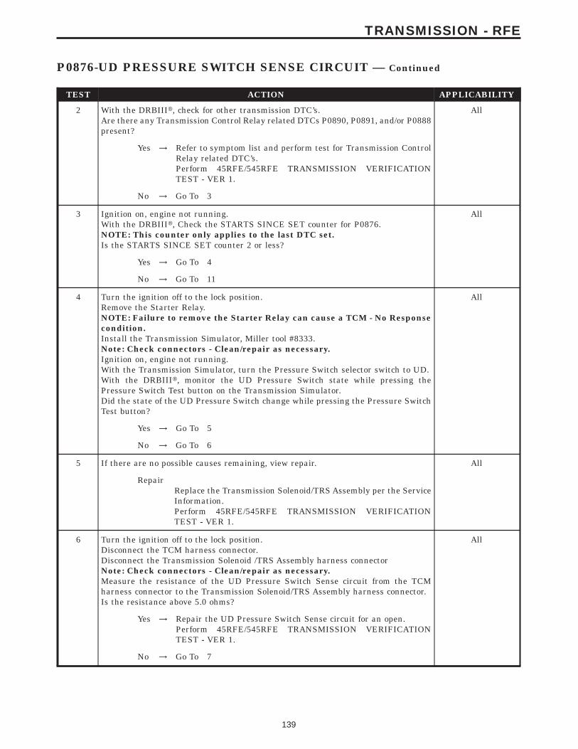
TEST ACTION APPLICABILITY
2 With the DRBIIIt, check for other transmission DTC’s.Are there any Transmission Control Relay related DTCs P0890, P0891, and/or P0888present?
All
Yes → Refer to symptom list and perform test for Transmission ControlRelay related DTC’s.Perform 45RFE/545RFE TRANSMISSION VERIFICATIONTEST - VER 1.
No → Go To 3
3 Ignition on, engine not running.With the DRBIIIt, Check the STARTS SINCE SET counter for P0876.NOTE: This counter only applies to the last DTC set.Is the STARTS SINCE SET counter 2 or less?
All
Yes → Go To 4
No → Go To 11
4 Turn the ignition off to the lock position.Remove the Starter Relay.NOTE: Failure to remove the Starter Relay can cause a TCM - No Responsecondition.Install the Transmission Simulator, Miller tool #8333.Note: Check connectors - Clean/repair as necessary.Ignition on, engine not running.With the Transmission Simulator, turn the Pressure Switch selector switch to UD.With the DRBIIIt, monitor the UD Pressure Switch state while pressing thePressure Switch Test button on the Transmission Simulator.Did the state of the UD Pressure Switch change while pressing the Pressure SwitchTest button?
All
Yes → Go To 5
No → Go To 6
5 If there are no possible causes remaining, view repair. All
RepairReplace the Transmission Solenoid/TRS Assembly per the ServiceInformation.Perform 45RFE/545RFE TRANSMISSION VERIFICATIONTEST - VER 1.
6 Turn the ignition off to the lock position.Disconnect the TCM harness connector.Disconnect the Transmission Solenoid /TRS Assembly harness connectorNote: Check connectors - Clean/repair as necessary.Measure the resistance of the UD Pressure Switch Sense circuit from the TCMharness connector to the Transmission Solenoid/TRS Assembly harness connector.Is the resistance above 5.0 ohms?
All
Yes → Repair the UD Pressure Switch Sense circuit for an open.Perform 45RFE/545RFE TRANSMISSION VERIFICATIONTEST - VER 1.
No → Go To 7
139
TRANSMISSION - RFE
P0876-UD PRESSURE SWITCH SENSE CIRCUIT — Continued
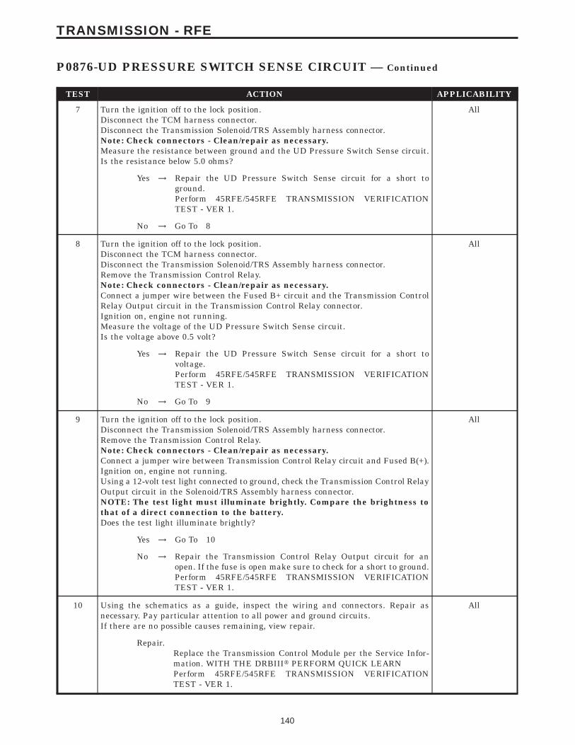
TEST ACTION APPLICABILITY
7 Turn the ignition off to the lock position.Disconnect the TCM harness connector.Disconnect the Transmission Solenoid/TRS Assembly harness connector.Note: Check connectors - Clean/repair as necessary.Measure the resistance between ground and the UD Pressure Switch Sense circuit.Is the resistance below 5.0 ohms?
All
Yes → Repair the UD Pressure Switch Sense circuit for a short toground.Perform 45RFE/545RFE TRANSMISSION VERIFICATIONTEST - VER 1.
No → Go To 8
8 Turn the ignition off to the lock position.Disconnect the TCM harness connector.Disconnect the Transmission Solenoid/TRS Assembly harness connector.Remove the Transmission Control Relay.Note: Check connectors - Clean/repair as necessary.Connect a jumper wire between the Fused B+ circuit and the Transmission ControlRelay Output circuit in the Transmission Control Relay connector.Ignition on, engine not running.Measure the voltage of the UD Pressure Switch Sense circuit.Is the voltage above 0.5 volt?
All
Yes → Repair the UD Pressure Switch Sense circuit for a short tovoltage.Perform 45RFE/545RFE TRANSMISSION VERIFICATIONTEST - VER 1.
No → Go To 9
9 Turn the ignition off to the lock position.Disconnect the Transmission Solenoid/TRS Assembly harness connector.Remove the Transmission Control Relay.Note: Check connectors - Clean/repair as necessary.Connect a jumper wire between Transmission Control Relay circuit and Fused B(+).Ignition on, engine not running.Using a 12-volt test light connected to ground, check the Transmission Control RelayOutput circuit in the Solenoid/TRS Assembly harness connector.NOTE: The test light must illuminate brightly. Compare the brightness tothat of a direct connection to the battery.Does the test light illuminate brightly?
All
Yes → Go To 10
No → Repair the Transmission Control Relay Output circuit for anopen. If the fuse is open make sure to check for a short to ground.Perform 45RFE/545RFE TRANSMISSION VERIFICATIONTEST - VER 1.
10 Using the schematics as a guide, inspect the wiring and connectors. Repair asnecessary. Pay particular attention to all power and ground circuits.If there are no possible causes remaining, view repair.
All
Repair.Replace the Transmission Control Module per the Service Infor-mation. WITH THE DRBIIIt PERFORM QUICK LEARNPerform 45RFE/545RFE TRANSMISSION VERIFICATIONTEST - VER 1.
140
TRANSMISSION - RFE
P0876-UD PRESSURE SWITCH SENSE CIRCUIT — Continued

TEST ACTION APPLICABILITY
11 The conditions necessary to set this DTC are not present at this time.Using the schematics as a guide, inspect the wiring and connectors specific to thiscircuit.Wiggle the wires while checking for shorts and open circuits.Check for a Primary Oil Filter not installed correctly and a dislodged Reverse CarrierSnap Ring which will typically set this DTC on heavy throttle acceleration from adead stop.With the DRBIIIt, check the EATX EVENT DATA to help identify the conditions inwhich the DTC was set.Were there any problems found?
All
Yes → Repair as necessary.Perform 45RFE/545RFE TRANSMISSION VERIFICATIONTEST - VER 1.
No → Test Complete.
141
TRANSMISSION - RFE
P0876-UD PRESSURE SWITCH SENSE CIRCUIT — Continued
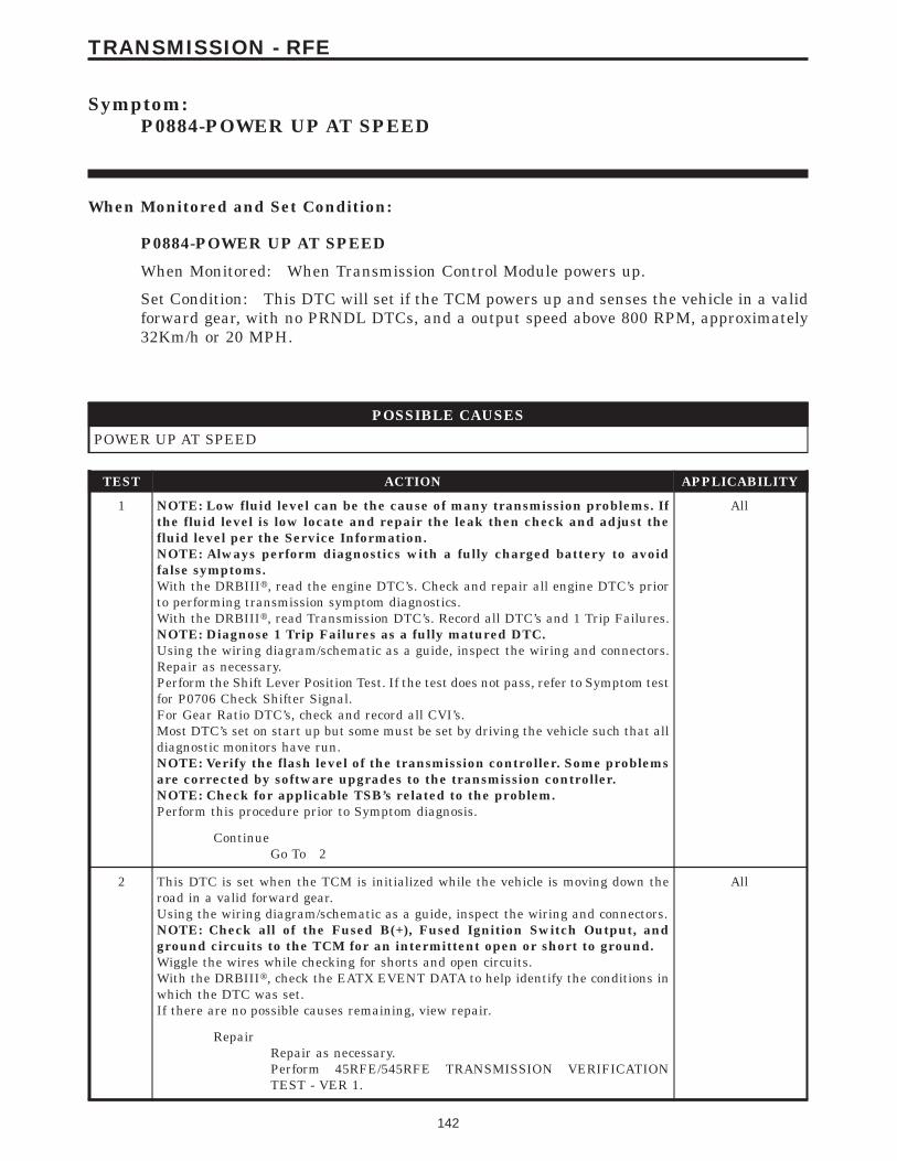
Symptom:P0884-POWER UP AT SPEED
When Monitored and Set Condition:
P0884-POWER UP AT SPEED
When Monitored: When Transmission Control Module powers up.
Set Condition: This DTC will set if the TCM powers up and senses the vehicle in a validforward gear, with no PRNDL DTCs, and a output speed above 800 RPM, approximately32Km/h or 20 MPH.
POSSIBLE CAUSES
POWER UP AT SPEED
TEST ACTION APPLICABILITY
1 NOTE: Low fluid level can be the cause of many transmission problems. Ifthe fluid level is low locate and repair the leak then check and adjust thefluid level per the Service Information.NOTE: Always perform diagnostics with a fully charged battery to avoidfalse symptoms.With the DRBIIIt, read the engine DTC’s. Check and repair all engine DTC’s priorto performing transmission symptom diagnostics.With the DRBIIIt, read Transmission DTC’s. Record all DTC’s and 1 Trip Failures.NOTE: Diagnose 1 Trip Failures as a fully matured DTC.Using the wiring diagram/schematic as a guide, inspect the wiring and connectors.Repair as necessary.Perform the Shift Lever Position Test. If the test does not pass, refer to Symptom testfor P0706 Check Shifter Signal.For Gear Ratio DTC’s, check and record all CVI’s.Most DTC’s set on start up but some must be set by driving the vehicle such that alldiagnostic monitors have run.NOTE: Verify the flash level of the transmission controller. Some problemsare corrected by software upgrades to the transmission controller.NOTE: Check for applicable TSB’s related to the problem.Perform this procedure prior to Symptom diagnosis.
All
ContinueGo To 2
2 This DTC is set when the TCM is initialized while the vehicle is moving down theroad in a valid forward gear.Using the wiring diagram/schematic as a guide, inspect the wiring and connectors.NOTE: Check all of the Fused B(+), Fused Ignition Switch Output, andground circuits to the TCM for an intermittent open or short to ground.Wiggle the wires while checking for shorts and open circuits.With the DRBIIIt, check the EATX EVENT DATA to help identify the conditions inwhich the DTC was set.If there are no possible causes remaining, view repair.
All
RepairRepair as necessary.Perform 45RFE/545RFE TRANSMISSION VERIFICATIONTEST - VER 1.
142
TRANSMISSION - RFE
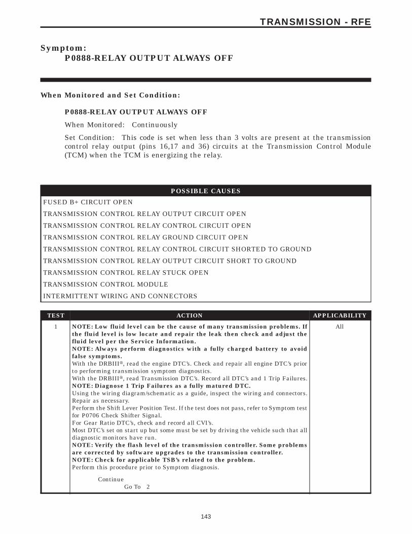
Symptom:P0888-RELAY OUTPUT ALWAYS OFF
When Monitored and Set Condition:
P0888-RELAY OUTPUT ALWAYS OFF
When Monitored: Continuously
Set Condition: This code is set when less than 3 volts are present at the transmissioncontrol relay output (pins 16,17 and 36) circuits at the Transmission Control Module(TCM) when the TCM is energizing the relay.
POSSIBLE CAUSES
FUSED B+ CIRCUIT OPEN
TRANSMISSION CONTROL RELAY OUTPUT CIRCUIT OPEN
TRANSMISSION CONTROL RELAY CONTROL CIRCUIT OPEN
TRANSMISSION CONTROL RELAY GROUND CIRCUIT OPEN
TRANSMISSION CONTROL RELAY CONTROL CIRCUIT SHORTED TO GROUND
TRANSMISSION CONTROL RELAY OUTPUT CIRCUIT SHORT TO GROUND
TRANSMISSION CONTROL RELAY STUCK OPEN
TRANSMISSION CONTROL MODULE
INTERMITTENT WIRING AND CONNECTORS
TEST ACTION APPLICABILITY
1 NOTE: Low fluid level can be the cause of many transmission problems. Ifthe fluid level is low locate and repair the leak then check and adjust thefluid level per the Service Information.NOTE: Always perform diagnostics with a fully charged battery to avoidfalse symptoms.With the DRBIIIt, read the engine DTC’s. Check and repair all engine DTC’s priorto performing transmission symptom diagnostics.With the DRBIIIt, read Transmission DTC’s. Record all DTC’s and 1 Trip Failures.NOTE: Diagnose 1 Trip Failures as a fully matured DTC.Using the wiring diagram/schematic as a guide, inspect the wiring and connectors.Repair as necessary.Perform the Shift Lever Position Test. If the test does not pass, refer to Symptom testfor P0706 Check Shifter Signal.For Gear Ratio DTC’s, check and record all CVI’s.Most DTC’s set on start up but some must be set by driving the vehicle such that alldiagnostic monitors have run.NOTE: Verify the flash level of the transmission controller. Some problemsare corrected by software upgrades to the transmission controller.NOTE: Check for applicable TSB’s related to the problem.Perform this procedure prior to Symptom diagnosis.
All
ContinueGo To 2
143
TRANSMISSION - RFE
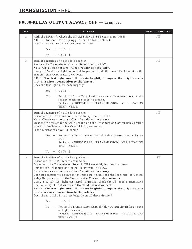
TEST ACTION APPLICABILITY
2 With the DRBIIIt, Check the STARTS SINCE SET counter for P0888.NOTE: This counter only applies to the last DTC set.Is the STARTS SINCE SET counter set to 0?
All
Yes → Go To 3
No → Go To 11
3 Turn the ignition off to the lock position.Remove the Transmission Control Relay from the PDC.Note: Check connectors - Clean/repair as necessary.Using a 12-volt test light connected to ground, check the Fused B(+) circuit in theTransmission Control Relay connector.NOTE: The test light must illuminate brightly. Compare the brightness tothat of a direct connection to the battery.Does the test light illuminate brightly?
All
Yes → Go To 4
No → Repair the Fused B(+) circuit for an open. If the fuse is open makesure to check for a short to ground.Perform 45RFE/545RFE TRANSMISSION VERIFICATIONTEST - VER 1.
4 Turn the ignition off to the lock position.Disconnect the Transmission Control Relay from the PDC.Note: Check connectors - Clean/repair as necessary.Measure the resistance between ground and the Transmission Control Relay groundcircuit in the Transmission Control Relay connector..Is the resistance above 5.0 ohms?
All
Yes → Repair the Transmission Control Relay Ground circuit for anopen.Perform 45RFE/545RFE TRANSMISSION VERIFICATIONTEST - VER 1.
No → Go To 5
5 Turn the ignition off to the lock position.Disconnect the TCM harness connector.Disconnect the Transmission Solenoid/TRS Assembly harness connector.Remove the Transmission Control Relay from the PDC.Note: Check connectors - Clean/repair as necessary.Connect a jumper wire between the Fused B(+) circuit and the Transmission ControlRelay Output circuit in the Transmission Control Relay connector.Using a 12-volt test light connected to ground, check the all three TransmissionControl Relay Output circuits in the TCM harness connector.NOTE: The test light must illuminate brightly. Compare the brightness tothat of a direct connection to the battery.Does the test light illuminate brightly on all three circuits?
All
Yes → Go To 6
No → Repair the Transmission Control Relay Output circuit for an openor high resistance.Perform 45RFE/545RFE TRANSMISSION VERIFICATIONTEST - VER 1.
144
TRANSMISSION - RFE
P0888-RELAY OUTPUT ALWAYS OFF — Continued

TEST ACTION APPLICABILITY
6 Turn the ignition off to the lock position.Disconnect the TCM harness connector.Remove the Transmission Control Relay from the PDC.Note: Check connectors - Clean/repair as necessary.Measure the resistance between ground and the Transmission Control Relay Outputcircuit.Is the resistance below 5.0 ohms?
All
Yes → Repair the Transmission Control Relay Output circuit for a shortto ground.Perform 45RFE/545RFE TRANSMISSION VERIFICATIONTEST - VER 1.
No → Go To 7
7 Turn the ignition off to the lock position.Disconnect the TCM harness connector.Remove the Transmission Control Relay from the PDC.Note: Check connectors - Clean/repair as necessary.Measure the resistance of the Transmission Control Relay Control circuit betweenthe Transmission Control Relay connector and the TCM harness connector.Is the resistance above 5.0 ohms?
All
Yes → Repair the Transmission Control Relay Control circuit for anopen.Perform 45RFE/545RFE TRANSMISSION VERIFICATIONTEST - VER 1.
No → Go To 8
8 Turn the ignition off to the lock position.Disconnect the TCM harness connector.Remove the Transmission Control Relay from the PDC.Note: Check connectors - Clean/repair as necessary.Measure the resistance between ground and the Transmission Control Relay Controlcircuit.Is the resistance below 5.0 ohms?
All
Yes → Repair the Transmission Control Relay Control circuit for a shortto ground.Perform 45RFE/545RFE TRANSMISSION VERIFICATIONTEST - VER 1.
No → Go To 9
9 Turn the ignition off to the lock position.Disconnect the TCM harness connector.Remove the Transmission Control RelayNote: Check connectors - Clean/repair as necessary.Connect a jumper wire between the Fused B(+) circuit and the Transmission ControlRelay Output circuit in the Transmission Control Relay connector.Measure the voltage of the Transmission Control Relay Output circuit in the TCMharness connector.Is the voltage above 10.0 volts?
All
Yes → Replace the Transmission Control Relay.Perform 45RFE/545RFE TRANSMISSION VERIFICATIONTEST - VER 1.
No → Go To 10
145
TRANSMISSION - RFE
P0888-RELAY OUTPUT ALWAYS OFF — Continued
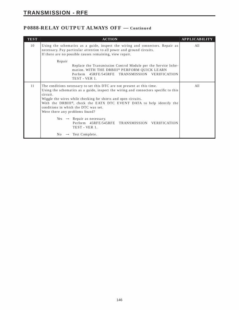
TEST ACTION APPLICABILITY
10 Using the schematics as a guide, inspect the wiring and connectors. Repair asnecessary. Pay particular attention to all power and ground circuits.If there are no possible causes remaining, view repair.
All
RepairReplace the Transmission Control Module per the Service Infor-mation. WITH THE DRBIIIt PERFORM QUICK LEARNPerform 45RFE/545RFE TRANSMISSION VERIFICATIONTEST - VER 1.
11 The conditions necessary to set this DTC are not present at this time.Using the schematics as a guide, inspect the wiring and connectors specific to thiscircuit.Wiggle the wires while checking for shorts and open circuits.With the DRBIIIt, check the EATX DTC EVENT DATA to help identify theconditions in which the DTC was set.Were there any problems found?
All
Yes → Repair as necessary.Perform 45RFE/545RFE TRANSMISSION VERIFICATIONTEST - VER 1.
No → Test Complete.
146
TRANSMISSION - RFE
P0888-RELAY OUTPUT ALWAYS OFF — Continued

Symptom:P0890-SWITCHED BATTERY
When Monitored and Set Condition:
P0890-SWITCHED BATTERY
When Monitored: Ignition key is turned from 9off9 position to 9run9 position and/orignition key is turned from 9crank9 position to 9run9 position.
Set Condition: This code is set if the Transmission Control Module (TCM) senses voltageon any of the pressure switch inputs prior to the TCM energizing the relay.
POSSIBLE CAUSES
PRESSURE SWITCH SENSE CIRCUIT SHORT TO VOLTAGE
TRANSMISSION CONTROL MODULE
INTERMITTENT WIRING AND CONNECTORS
TEST ACTION APPLICABILITY
1 NOTE: Low fluid level can be the cause of many transmission problems. Ifthe fluid level is low locate and repair the leak then check and adjust thefluid level per the Service Information.NOTE: Always perform diagnostics with a fully charged battery to avoidfalse symptoms.With the DRBIIIt, read the engine DTC’s. Check and repair all engine DTC’s priorto performing transmission symptom diagnostics.With the DRBIIIt, read Transmission DTC’s. Record all DTC’s and 1 Trip Failures.NOTE: Diagnose 1 Trip Failures as a fully matured DTC.Using the wiring diagram/schematic as a guide, inspect the wiring and connectors.Repair as necessary.Perform the Shift Lever Position Test. If the test does not pass, refer to Symptom testfor P0706 Check Shifter Signal.For Gear Ratio DTC’s, check and record all CVI’s.Most DTC’s set on start up but some must be set by driving the vehicle such that alldiagnostic monitors have run.NOTE: Verify the flash level of the transmission controller. Some problemsare corrected by software upgrades to the transmission controller.NOTE: Check for applicable TSB’s related to the problem.Perform this procedure prior to Symptom diagnosis.
All
ContinueGo To 2
2 With the DRBIIIt, Check the STARTS SINCE SET counter for P0890.NOTE: This counter only applies to the last DTC set.Is the 9Starts Since Set9 counter equal to zero?
All
Yes → Go To 3
No → Go To 5
147
TRANSMISSION - RFE
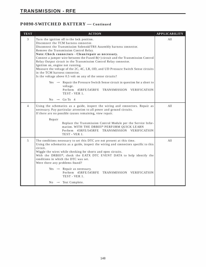
TEST ACTION APPLICABILITY
3 Turn the ignition off to the lock position.Disconnect the TCM harness connector.Disconnect the Transmission Solenoid/TRS Assembly harness connector.Remove the Transmission Control Relay.Note: Check connectors - Clean/repair as necessary.Connect a jumper wire between the Fused B(+) circuit and the Transmission ControlRelay Output circuit in the Transmission Control Relay connector.Ignition on, engine not running.Measure the voltage of the 2C, 4C, LR, OD, and UD Pressure Switch Sense circuitsin the TCM harness connector.Is the voltage above 0.5 volt on any of the sense circuits?
All
Yes → Repair the Pressure Switch Sense circuit in question for a short tovoltage.Perform 45RFE/545RFE TRANSMISSION VERIFICATIONTEST - VER 1.
No → Go To 4
4 Using the schematics as a guide, inspect the wiring and connectors. Repair asnecessary. Pay particular attention to all power and ground circuits.If there are no possible causes remaining, view repair.
All
RepairReplace the Transmission Control Module per the Service Infor-mation. WITH THE DRBIIIt PERFORM QUICK LEARNPerform 45RFE/545RFE TRANSMISSION VERIFICATIONTEST - VER 1.
5 The conditions necessary to set this DTC are not present at this time.Using the schematics as a guide, inspect the wiring and connectors specific to thiscircuit.Wiggle the wires while checking for shorts and open circuits.With the DRBIIIt, check the EATX DTC EVENT DATA to help identify theconditions in which the DTC was set.Were there any problems found?
All
Yes → Repair as necessary.Perform 45RFE/545RFE TRANSMISSION VERIFICATIONTEST - VER 1.
No → Test Complete.
148
TRANSMISSION - RFE
P0890-SWITCHED BATTERY — Continued

Symptom:P0891-TRANSMISSION RELAY ALWAYS ON
When Monitored and Set Condition:
P0891-TRANSMISSION RELAY ALWAYS ON
When Monitored: When ignition key is turned from 9off9 position to 9run9 position and/orignition key is turned from 9crank9 position to 9run9 position.
Set Condition: This code is set if the Transmission Control Module (TCM) senses greaterthan 3 volts at the Trans Control Relay Output terminal(s) of the TCM prior to the TCMenergizing the relay.
POSSIBLE CAUSES
TRANSMISSION CONTROL RELAY CONTROL CIRCUIT SHORT TO VOLTAGE
TRANSMISSION CONTROL RELAY OUTPUT CIRCUIT SHORT TO VOLTAGE
TRANSMISSION CONTROL RELAY STUCK CLOSED
TRANSMISSION CONTROL MODULE
INTERMITTENT WIRING AND CONNECTORS
TEST ACTION APPLICABILITY
1 NOTE: Low fluid level can be the cause of many transmission problems. Ifthe fluid level is low locate and repair the leak then check and adjust thefluid level per the Service Information.NOTE: Always perform diagnostics with a fully charged battery to avoidfalse symptoms.With the DRBIIIt, read the engine DTC’s. Check and repair all engine DTC’s priorto performing transmission symptom diagnostics.With the DRBIIIt, read Transmission DTC’s. Record all DTC’s and 1 Trip Failures.NOTE: Diagnose 1 Trip Failures as a fully matured DTC.Using the wiring diagram/schematic as a guide, inspect the wiring and connectors.Repair as necessary.Perform the Shift Lever Position Test. If the test does not pass, refer to Symptom testfor P0706 Check Shifter Signal.For Gear Ratio DTC’s, check and record all CVI’s.Most DTC’s set on start up but some must be set by driving the vehicle such that alldiagnostic monitors have run.NOTE: Verify the flash level of the transmission controller. Some problemsare corrected by software upgrades to the transmission controller.NOTE: Check for applicable TSB’s related to the problem.Perform this procedure prior to Symptom diagnosis.
All
ContinueGo To 2
149
TRANSMISSION - RFE
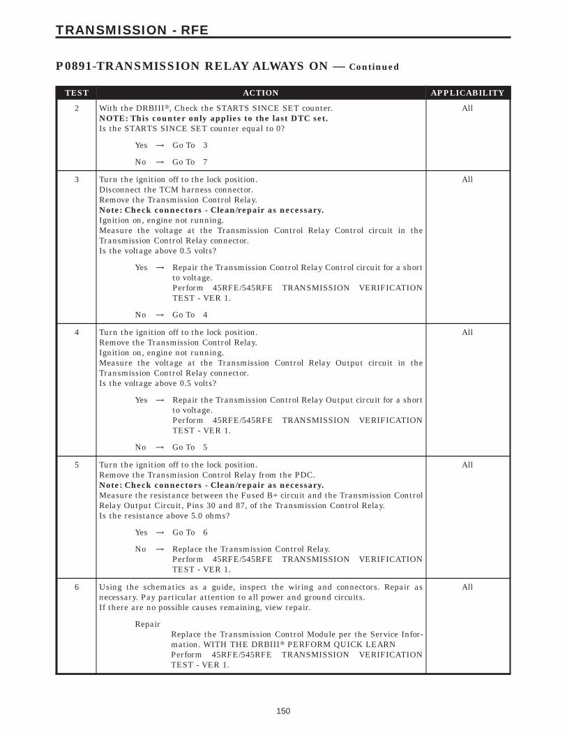
TEST ACTION APPLICABILITY
2 With the DRBIIIt, Check the STARTS SINCE SET counter.NOTE: This counter only applies to the last DTC set.Is the STARTS SINCE SET counter equal to 0?
All
Yes → Go To 3
No → Go To 7
3 Turn the ignition off to the lock position.Disconnect the TCM harness connector.Remove the Transmission Control Relay.Note: Check connectors - Clean/repair as necessary.Ignition on, engine not running.Measure the voltage at the Transmission Control Relay Control circuit in theTransmission Control Relay connector.Is the voltage above 0.5 volts?
All
Yes → Repair the Transmission Control Relay Control circuit for a shortto voltage.Perform 45RFE/545RFE TRANSMISSION VERIFICATIONTEST - VER 1.
No → Go To 4
4 Turn the ignition off to the lock position.Remove the Transmission Control Relay.Ignition on, engine not running.Measure the voltage at the Transmission Control Relay Output circuit in theTransmission Control Relay connector.Is the voltage above 0.5 volts?
All
Yes → Repair the Transmission Control Relay Output circuit for a shortto voltage.Perform 45RFE/545RFE TRANSMISSION VERIFICATIONTEST - VER 1.
No → Go To 5
5 Turn the ignition off to the lock position.Remove the Transmission Control Relay from the PDC.Note: Check connectors - Clean/repair as necessary.Measure the resistance between the Fused B+ circuit and the Transmission ControlRelay Output Circuit, Pins 30 and 87, of the Transmission Control Relay.Is the resistance above 5.0 ohms?
All
Yes → Go To 6
No → Replace the Transmission Control Relay.Perform 45RFE/545RFE TRANSMISSION VERIFICATIONTEST - VER 1.
6 Using the schematics as a guide, inspect the wiring and connectors. Repair asnecessary. Pay particular attention to all power and ground circuits.If there are no possible causes remaining, view repair.
All
RepairReplace the Transmission Control Module per the Service Infor-mation. WITH THE DRBIIIt PERFORM QUICK LEARNPerform 45RFE/545RFE TRANSMISSION VERIFICATIONTEST - VER 1.
150
TRANSMISSION - RFE
P0891-TRANSMISSION RELAY ALWAYS ON — Continued

TEST ACTION APPLICABILITY
7 The conditions necessary to set this DTC are not present at this time.Using the schematics as a guide, inspect the wiring and connectors specific to thiscircuit.Wiggle the wires while checking for shorts and open circuits.With the DRBIIIt, check the EATX DTC EVENT DATA to help identify theconditions in which the DTC was set.Were there any problems found?
All
Yes → Repair as necessary.Perform 45RFE/545RFE TRANSMISSION VERIFICATIONTEST - VER 1.
No → Test Complete.
151
TRANSMISSION - RFE
P0891-TRANSMISSION RELAY ALWAYS ON — Continued

Symptom:P0932-LINE PRESSURE SENSOR CIRCUIT FAULT
When Monitored and Set Condition:
P0932-LINE PRESSURE SENSOR CIRCUIT FAULT
When Monitored: Continuously while driving in a forward gear.
Set Condition: The PCM continuously monitors Actual Line Pressure and compares it toDesired Line Pressure. If the Actual Line Pressure reading is more than 172.4 kPa (25 psi)higher than the Desired Line Pressure, but is less than the highest Line Pressure everused in the current gear, this code will set.
POSSIBLE CAUSES
RELATED DTC’S PRESENT
POOR CONNECTION OR WIRING
INTERNAL TRANSMISSION
TRANSMISSION CONTROL MODULE
INTERMITTENT WIRING AND CONNECTORS
TEST ACTION APPLICABILITY
1 NOTE: Low fluid level can be the cause of many transmission problems. Ifthe fluid level is low locate and repair the leak then check and adjust thefluid level per the Service Information.NOTE: Always perform diagnostics with a fully charged battery to avoidfalse symptoms.With the DRBIIIt, read the engine DTC’s. Check and repair all engine DTC’s priorto performing transmission symptom diagnostics.With the DRBIIIt, read Transmission DTC’s. Record all DTC’s and 1 Trip Failures.NOTE: Diagnose 1 Trip Failures as a fully matured DTC.Using the wiring diagram/schematic as a guide, inspect the wiring and connectors.Repair as necessary.Perform the Shift Lever Position Test. If the test does not pass, refer to Symptom testfor P0706 Check Shifter Signal.For Gear Ratio DTC’s, check and record all CVI’s.Most DTC’s set on start up but some must be set by driving the vehicle such that alldiagnostic monitors have run.NOTE: Verify the flash level of the transmission controller. Some problemsare corrected by software upgrades to the transmission controller.NOTE: Check for applicable TSB’s related to the problem.Perform this procedure prior to Symptom diagnosis.
All
ContinueGo To 2
152
TRANSMISSION - RFE

TEST ACTION APPLICABILITY
2 With the DRBIIIt, check for other transmission DTC’s.Are there any other line pressure related DTC’s P0934, P0935, P0868, or P0869present?
All
Yes → Refer to the Transmission category and perform the appropriatesymptom. If the DTC P0934 and/or P0935 are present, performthese tests first.Perform 45RFE/545RFE TRANSMISSION VERIFICATIONTEST - VER 1.
No → Go To 3
3 CAUTION: Apply Parking BrakeStart the engine.CAUTION: Firmly apply the brakes.With the DRBIIIt, monitor the Line Pressure, Desired Line Pressure and the TPSDegree.While firmly applying the brakes place shifter in the R position. Then slowly pressthe accelerator pedal to a TPS degree of 15.Compare the Line Pressure reading to the Desired Line Pressure reading on theDRBIIIt.Does the Line Pressure and Desired Line Pressure stay within ± 34 kPa or 5 PSI?
All
No → Go To 4
Yes → Go To 8
4 With the DRBIIIt, monitor the Line Pressure Sensor voltage while wiggling thewiring harness and connectors pertaining to the Line Pressure Sensor and theTransmission Solenoid/TRS Assembly.Did the voltage remain steady while wiggling the wiring harness and connectors?
All
Yes → Go To 5
No → Repair as necessary.Perform 45RFE/545RFE TRANSMISSION VERIFICATIONTEST - VER 1.
5 Turn the ignition off to the lock position.Remove the Starter Relay.NOTE: Failure to remove the Starter Relay can cause a Transmission - NoResponse condition.Install Transmission Simulator Miller tool #8333.With the Transmission Simulator select the 9OFF9 position on the 9Input/OutputSpeed9 switch.Ignition on, engine not running.With the DRBIIIt, monitor the Line Pressure during the following step.Using the Transmission Simulator, turn the selector switch to each of the 3 LinePressure positions.NOTE: All three DRBIIIt Line Pressure readings should be steady and ± 2.0PSI of the reading specified on the Transmission Simulator.Does the Line Pressure fluctuate up and down more than 69 kPa or 10 PSI at any ofthe positions?
All
Yes → Go To 6
No → Go To 7
153
TRANSMISSION - RFE
P0932-LINE PRESSURE SENSOR CIRCUIT FAULT — Continued
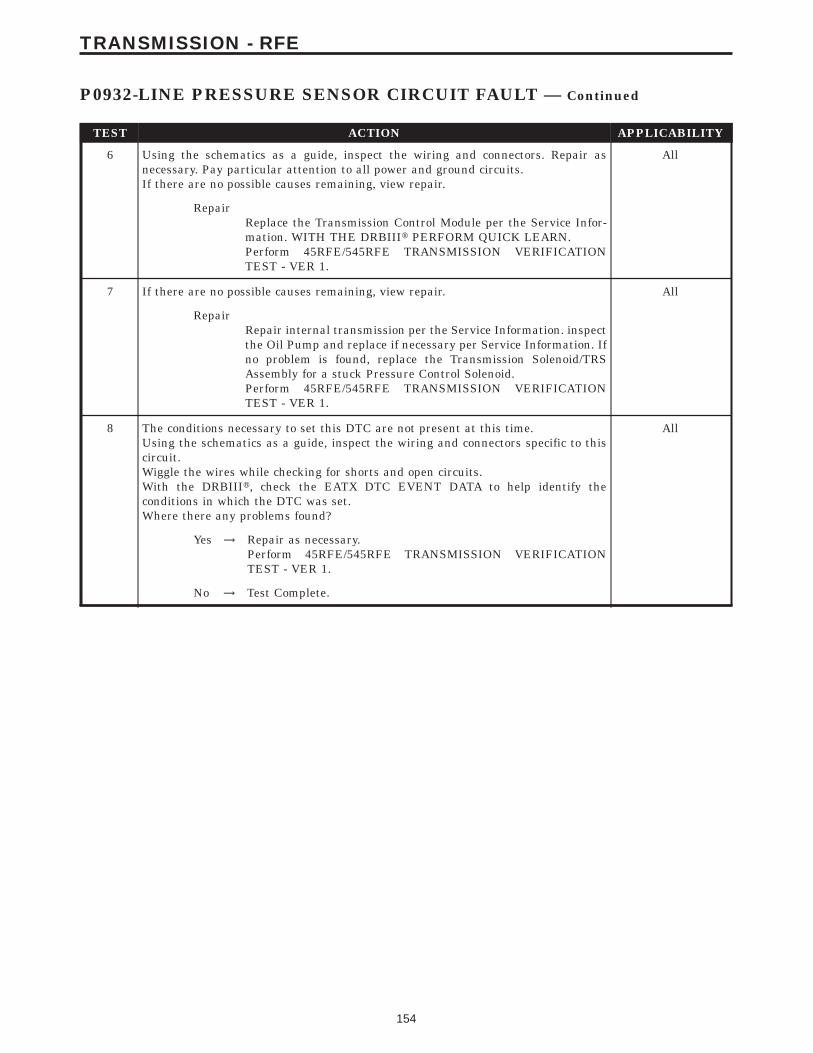
TEST ACTION APPLICABILITY
6 Using the schematics as a guide, inspect the wiring and connectors. Repair asnecessary. Pay particular attention to all power and ground circuits.If there are no possible causes remaining, view repair.
All
RepairReplace the Transmission Control Module per the Service Infor-mation. WITH THE DRBIIIt PERFORM QUICK LEARN.Perform 45RFE/545RFE TRANSMISSION VERIFICATIONTEST - VER 1.
7 If there are no possible causes remaining, view repair. All
RepairRepair internal transmission per the Service Information. inspectthe Oil Pump and replace if necessary per Service Information. Ifno problem is found, replace the Transmission Solenoid/TRSAssembly for a stuck Pressure Control Solenoid.Perform 45RFE/545RFE TRANSMISSION VERIFICATIONTEST - VER 1.
8 The conditions necessary to set this DTC are not present at this time.Using the schematics as a guide, inspect the wiring and connectors specific to thiscircuit.Wiggle the wires while checking for shorts and open circuits.With the DRBIIIt, check the EATX DTC EVENT DATA to help identify theconditions in which the DTC was set.Where there any problems found?
All
Yes → Repair as necessary.Perform 45RFE/545RFE TRANSMISSION VERIFICATIONTEST - VER 1.
No → Test Complete.
154
TRANSMISSION - RFE
P0932-LINE PRESSURE SENSOR CIRCUIT FAULT — Continued
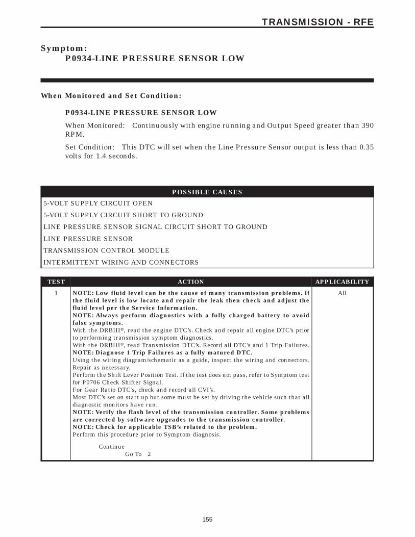
Symptom:P0934-LINE PRESSURE SENSOR LOW
When Monitored and Set Condition:
P0934-LINE PRESSURE SENSOR LOW
When Monitored: Continuously with engine running and Output Speed greater than 390RPM.
Set Condition: This DTC will set when the Line Pressure Sensor output is less than 0.35volts for 1.4 seconds.
POSSIBLE CAUSES
5-VOLT SUPPLY CIRCUIT OPEN
5-VOLT SUPPLY CIRCUIT SHORT TO GROUND
LINE PRESSURE SENSOR SIGNAL CIRCUIT SHORT TO GROUND
LINE PRESSURE SENSOR
TRANSMISSION CONTROL MODULE
INTERMITTENT WIRING AND CONNECTORS
TEST ACTION APPLICABILITY
1 NOTE: Low fluid level can be the cause of many transmission problems. Ifthe fluid level is low locate and repair the leak then check and adjust thefluid level per the Service Information.NOTE: Always perform diagnostics with a fully charged battery to avoidfalse symptoms.With the DRBIIIt, read the engine DTC’s. Check and repair all engine DTC’s priorto performing transmission symptom diagnostics.With the DRBIIIt, read Transmission DTC’s. Record all DTC’s and 1 Trip Failures.NOTE: Diagnose 1 Trip Failures as a fully matured DTC.Using the wiring diagram/schematic as a guide, inspect the wiring and connectors.Repair as necessary.Perform the Shift Lever Position Test. If the test does not pass, refer to Symptom testfor P0706 Check Shifter Signal.For Gear Ratio DTC’s, check and record all CVI’s.Most DTC’s set on start up but some must be set by driving the vehicle such that alldiagnostic monitors have run.NOTE: Verify the flash level of the transmission controller. Some problemsare corrected by software upgrades to the transmission controller.NOTE: Check for applicable TSB’s related to the problem.Perform this procedure prior to Symptom diagnosis.
All
ContinueGo To 2
155
TRANSMISSION - RFE

TEST ACTION APPLICABILITY
2 With the DRBIIIt, Check the STARTS SINCE SET counter.NOTE: This counter only applies to the last DTC set.Is the STARTS SINCE SET counter 2 or less?
All
Yes → Go To 3
No → Go To 9
3 Turn the ignition off to the lock position.Remove the Starter Relay.NOTE: Failure to remove the Starter Relay can cause a Transmission - NoResponse condition.Install the Transmission Simulator Miller tool #8333.Ignition on, engine not running.With the DRBIIIt, monitor the Line Pressure.Using the Transmission Simulator, set the rotary switch to each of the 3 line pressurepositions.Note: The readings should be within ± 2.0 PSI on the DRBIIIt of the pressure readingspecified on Transmission Simulator.Does the Line Pressure on the DRBIIIt match the pressures on the TransmissionSimulator?
All
Yes → Go To 4
No → Go To 5
4 If there are no possible causes remaining, view repair. All
RepairReplace the Line Pressure Sensor per the Service Information.Perform 45RFE/545RFE TRANSMISSION VERIFICATIONTEST - VER 1.
5 Turn the ignition off to the lock position.Disconnect the TCM harness connector.Disconnect the Line Pressure Sensor connector.Note: Check connectors - Clean/repair as necessary.Measure the resistance of the 5-volt Supply circuit from the Line Pressure Sensorharness connector to the TCM harness connector.Is the resistance above 5.0 ohms?
All
Yes → Repair the 5-volt Supply circuit for an open.Perform 45RFE/545RFE TRANSMISSION VERIFICATIONTEST - VER 1.
No → Go To 6
6 Turn the ignition off to the lock position.Disconnect the TCM harness connector.Disconnect the Line Pressure Sensor harness connector.Note: Check connectors - Clean/repair as necessary.Measure the resistance between ground and the 5-volt Supply circuit.Is the resistance below 5.0 ohms?
All
Yes → Repair the 5-volt Supply circuit for a short to ground.Perform 45RFE/545RFE TRANSMISSION VERIFICATIONTEST - VER 1.
No → Go To 7
156
TRANSMISSION - RFE
P0934-LINE PRESSURE SENSOR LOW — Continued
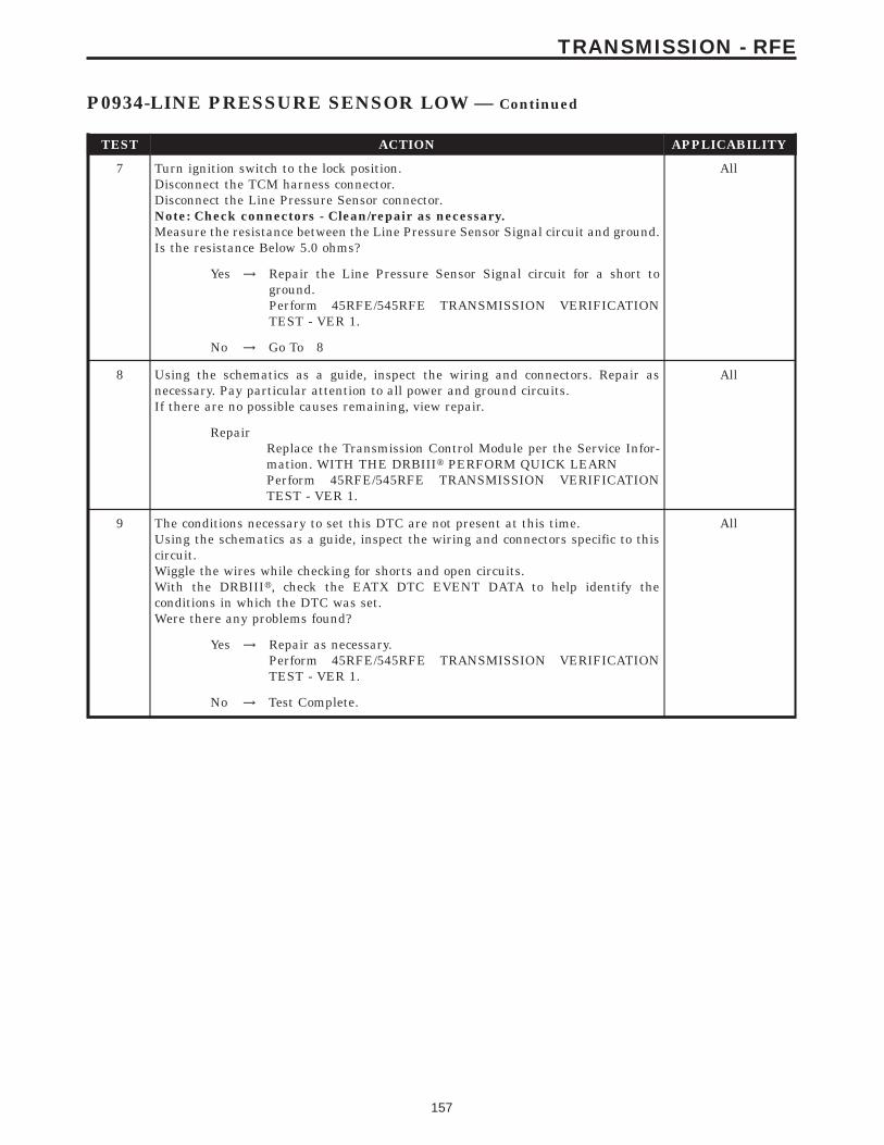
TEST ACTION APPLICABILITY
7 Turn ignition switch to the lock position.Disconnect the TCM harness connector.Disconnect the Line Pressure Sensor connector.Note: Check connectors - Clean/repair as necessary.Measure the resistance between the Line Pressure Sensor Signal circuit and ground.Is the resistance Below 5.0 ohms?
All
Yes → Repair the Line Pressure Sensor Signal circuit for a short toground.Perform 45RFE/545RFE TRANSMISSION VERIFICATIONTEST - VER 1.
No → Go To 8
8 Using the schematics as a guide, inspect the wiring and connectors. Repair asnecessary. Pay particular attention to all power and ground circuits.If there are no possible causes remaining, view repair.
All
RepairReplace the Transmission Control Module per the Service Infor-mation. WITH THE DRBIIIt PERFORM QUICK LEARNPerform 45RFE/545RFE TRANSMISSION VERIFICATIONTEST - VER 1.
9 The conditions necessary to set this DTC are not present at this time.Using the schematics as a guide, inspect the wiring and connectors specific to thiscircuit.Wiggle the wires while checking for shorts and open circuits.With the DRBIIIt, check the EATX DTC EVENT DATA to help identify theconditions in which the DTC was set.Were there any problems found?
All
Yes → Repair as necessary.Perform 45RFE/545RFE TRANSMISSION VERIFICATIONTEST - VER 1.
No → Test Complete.
157
TRANSMISSION - RFE
P0934-LINE PRESSURE SENSOR LOW — Continued
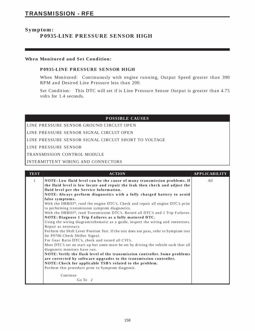
Symptom:P0935-LINE PRESSURE SENSOR HIGH
When Monitored and Set Condition:
P0935-LINE PRESSURE SENSOR HIGH
When Monitored: Continuously with engine running, Output Speed greater than 390RPM and Desired Line Pressure less than 200.
Set Condition: This DTC will set if is Line Pressure Sensor Output is greater than 4.75volts for 1.4 seconds.
POSSIBLE CAUSES
LINE PRESSURE SENSOR GROUND CIRCUIT OPEN
LINE PRESSURE SENSOR SIGNAL CIRCUIT OPEN
LINE PRESSURE SENSOR SIGNAL CIRCUIT SHORT TO VOLTAGE
LINE PRESSURE SENSOR
TRANSMISSION CONTROL MODULE
INTERMITTENT WIRING AND CONNECTORS
TEST ACTION APPLICABILITY
1 NOTE: Low fluid level can be the cause of many transmission problems. Ifthe fluid level is low locate and repair the leak then check and adjust thefluid level per the Service Information.NOTE: Always perform diagnostics with a fully charged battery to avoidfalse symptoms.With the DRBIIIt, read the engine DTC’s. Check and repair all engine DTC’s priorto performing transmission symptom diagnostics.With the DRBIIIt, read Transmission DTC’s. Record all DTC’s and 1 Trip Failures.NOTE: Diagnose 1 Trip Failures as a fully matured DTC.Using the wiring diagram/schematic as a guide, inspect the wiring and connectors.Repair as necessary.Perform the Shift Lever Position Test. If the test does not pass, refer to Symptom testfor P0706 Check Shifter Signal.For Gear Ratio DTC’s, check and record all CVI’s.Most DTC’s set on start up but some must be set by driving the vehicle such that alldiagnostic monitors have run.NOTE: Verify the flash level of the transmission controller. Some problemsare corrected by software upgrades to the transmission controller.NOTE: Check for applicable TSB’s related to the problem.Perform this procedure prior to Symptom diagnosis.
All
ContinueGo To 2
158
TRANSMISSION - RFE

TEST ACTION APPLICABILITY
2 With the DRBIIIt, Check the STARTS SINCE SET counter.NOTE: This counter only applies to the last DTC set.Is the STARTS SINCE SET counter 2 or less?
All
Yes → Go To 3
No → Go To 9
3 Turn the ignition off to the lock position.Remove the Starter Relay.NOTE: Failure to remove the Starter Relay can cause a Transmission - NoResponse condition.Install the Transmission Simulator, Miller tool #8333.Ignition on, engine not running.With the DRBIIIt, monitor the Line Pressure.Using the Transmission Simulator, set the rotary switch to each of the 3 line pressurepositions.Note: The readings should be within ± 2.0 PSI on the DRBIIIt of the pressure readingspecified on Transmission Simulator.Does the Line Pressure on the DRBIIIt match the pressures on the TransmissionSimulator?
All
Yes → Go To 4
No → Go To 5
4 If there are no possible causes remaining, view repair. All
RepairReplace the Line Pressure Sensor per the Service Information.Perform 45RFE/545RFE TRANSMISSION VERIFICATIONTEST - VER 1.
5 Turn the ignition off to the lock position.Disconnect the TCM harness connector.Disconnect the Line Pressure Sensor connector.Note: Check connectors - Clean/repair as necessary.Measure the resistance of the Ground circuit from the Line Pressure Sensor harnessconnector to the TCM harness connector.Is the resistance above 5.0 ohms?
All
Yes → Repair the Ground circuit for an open.Perform 45RFE/545RFE TRANSMISSION VERIFICATIONTEST - VER 1.
No → Go To 6
6 Turn the ignition off to the lock position.Disconnect the TCM harness connector.Disconnect the Line Pressure Sensor harness connector.Note: Check connectors - Clean/repair as necessary.Measure the resistance of the Line Pressure Sensor Signal circuit from the LinePressure Sensor harness connector to the TCM harness connector.Is the resistance above 5.0 ohms?
All
Yes → Repair the Line Pressure Sensor Signal circuit for an open.Perform 45RFE/545RFE TRANSMISSION VERIFICATIONTEST - VER 1.
No → Go To 7
159
TRANSMISSION - RFE
P0935-LINE PRESSURE SENSOR HIGH — Continued

TEST ACTION APPLICABILITY
7 Turn the ignition off to the lock position.Disconnect the TCM harness connector.Remove the Transmission Control Relay.Note: Check connectors - Clean/repair as necessary.Connect a jumper wire between the Fused B+ circuit and the Transmission ControlRelay Output circuit in the Transmission Relay connector.Turn ignition on.Measure the voltage of the Line Pressure Sensor Signal circuit.Is the voltage above 5.5 volts?
All
Yes → Repair the Line Pressure Sensor Signal circuit for a short tovoltage.Perform 45RFE/545RFE TRANSMISSION VERIFICATIONTEST - VER 1.
No → Go To 8
8 Using the schematics as a guide, inspect the wiring and connectors. Repair asnecessary. Pay particular attention to all power and ground circuits.If there are no possible causes remaining, view repair.
All
RepairReplace the Transmission Control Module per the Service Infor-mation. WITH THE DRBIIIt PERFORM QUICK LEARNPerform 45RFE/545RFE TRANSMISSION VERIFICATIONTEST - VER 1.
9 The conditions necessary to set this DTC are not present at this time.Using the schematics as a guide, inspect the wiring and connectors specific to thiscircuit.Wiggle the wires while checking for shorts and open circuits.With the DRBIIIt, check the EATX DTC EVENT DATA to help identify theconditions in which the DTC was set.Were there any problems found?
All
Yes → Repair as necessary.Perform 45RFE/545RFE TRANSMISSION VERIFICATIONTEST - VER 1.
No → Test Complete.
160
TRANSMISSION - RFE
P0935-LINE PRESSURE SENSOR HIGH — Continued
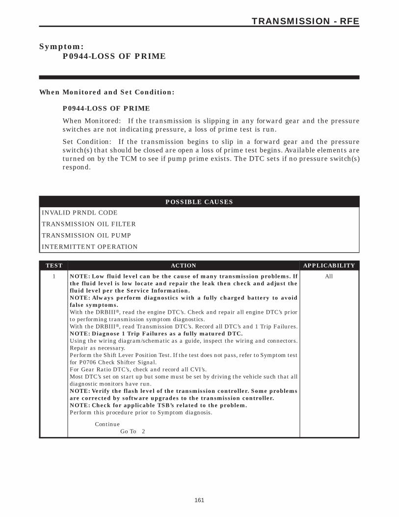
Symptom:P0944-LOSS OF PRIME
When Monitored and Set Condition:
P0944-LOSS OF PRIME
When Monitored: If the transmission is slipping in any forward gear and the pressureswitches are not indicating pressure, a loss of prime test is run.
Set Condition: If the transmission begins to slip in a forward gear and the pressureswitch(s) that should be closed are open a loss of prime test begins. Available elements areturned on by the TCM to see if pump prime exists. The DTC sets if no pressure switch(s)respond.
POSSIBLE CAUSES
INVALID PRNDL CODE
TRANSMISSION OIL FILTER
TRANSMISSION OIL PUMP
INTERMITTENT OPERATION
TEST ACTION APPLICABILITY
1 NOTE: Low fluid level can be the cause of many transmission problems. Ifthe fluid level is low locate and repair the leak then check and adjust thefluid level per the Service Information.NOTE: Always perform diagnostics with a fully charged battery to avoidfalse symptoms.With the DRBIIIt, read the engine DTC’s. Check and repair all engine DTC’s priorto performing transmission symptom diagnostics.With the DRBIIIt, read Transmission DTC’s. Record all DTC’s and 1 Trip Failures.NOTE: Diagnose 1 Trip Failures as a fully matured DTC.Using the wiring diagram/schematic as a guide, inspect the wiring and connectors.Repair as necessary.Perform the Shift Lever Position Test. If the test does not pass, refer to Symptom testfor P0706 Check Shifter Signal.For Gear Ratio DTC’s, check and record all CVI’s.Most DTC’s set on start up but some must be set by driving the vehicle such that alldiagnostic monitors have run.NOTE: Verify the flash level of the transmission controller. Some problemsare corrected by software upgrades to the transmission controller.NOTE: Check for applicable TSB’s related to the problem.Perform this procedure prior to Symptom diagnosis.
All
ContinueGo To 2
161
TRANSMISSION - RFE
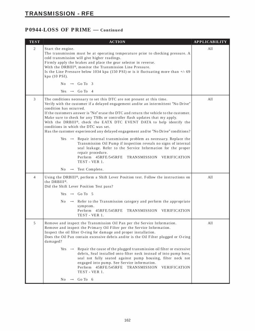
TEST ACTION APPLICABILITY
2 Start the engine.The transmission must be at operating temperature prior to checking pressure. Acold transmission will give higher readings.Firmly apply the brakes and place the gear selector in reverse.With the DRBIIIt, monitor the Transmission Line Pressure.Is the Line Pressure below 1034 kpa (150 PSI) or is it fluctuating more than +/- 69kpa (10 PSI).
All
No → Go To 3
Yes → Go To 4
3 The conditions necessary to set this DTC are not present at this time.Verify with the customer if a delayed engagement and/or an intermittent 9No Drive9condition has occurred.If the customers answer is 9No9 erase the DTC and return the vehicle to the customer.Make sure to check for any TSBs or controller flash updates that my apply.With the DRBIIIt, check the EATX DTC EVENT DATA to help identify theconditions in which the DTC was set.Has the customer experienced any delayed engagement and/or 9No Drive9 conditions?
All
Yes → Repair internal transmission problem as necessary. Replace theTransmission Oil Pump if inspection reveals no signs of internalseal leakage. Refer to the Service Information for the properrepair procedure.Perform 45RFE/545RFE TRANSMISSION VERIFICATIONTEST - VER 1.
No → Test Complete.
4 Using the DRBIIIt, perform a Shift Lever Position test. Follow the instructions onthe DRBIIIt.Did the Shift Lever Position Test pass?
All
Yes → Go To 5
No → Refer to the Transmission category and perform the appropriatesymptom.Perform 45RFE/545RFE TRANSMISSION VERIFICATIONTEST - VER 1.
5 Remove and inspect the Transmission Oil Pan per the Service Information.Remove and inspect the Primary Oil Filter per the Service Information.Inspect the oil filter O-ring for damage and proper installation.Does the Oil Pan contain excessive debris and/or is the Oil Filter plugged or O-ringdamaged?
All
Yes → Repair the cause of the plugged transmission oil filter or excessivedebris, Seal installed onto filter neck instead of into pump bore,seal not fully seated against pump housing, filter neck notengaged into pump. See Service information.Perform 45RFE/545RFE TRANSMISSION VERIFICATIONTEST - VER 1.
No → Go To 6
162
TRANSMISSION - RFE
P0944-LOSS OF PRIME — Continued

TEST ACTION APPLICABILITY
6 If there are no possible causes remaining, view repair. All
RepairRepair or replace the Transmission Oil Pump as necessary. Referto the Service Information for the proper repair procedure.Perform 45RFE/545RFE TRANSMISSION VERIFICATIONTEST - VER 1.
163
TRANSMISSION - RFE
P0944-LOSS OF PRIME — Continued

Symptom:P0987-4C HYDRAULIC PRESSURE TEST FAILURE
When Monitored and Set Condition:
P0987-4C HYDRAULIC PRESSURE TEST FAILURE
When Monitored: In any forward gear with engine speed above 1000 RPM shortly aftera shift and every minute thereafter.
Set Condition: After a shift into a forward gear, with engine speed > 1000 RPM, the TCMmomentarily turns on element pressure to the clutch circuits that don’t have pressure toidentify the correct pressure switch closes. If the pressure switch does not close 2 times theDTC sets
POSSIBLE CAUSES
LINE PRESSURE DTC’S PRESENT
POOR LINE PRESSURE SENSOR CONNECTION
4C PRESSURE SWITCH SENSE CIRCUIT OPEN
5-VOLT SUPPLY CIRCUIT OPEN
TRANSMISSION CONTROL RELAY OUTPUT CIRCUIT OPEN
4C PRESSURE SWITCH SENSE CIRCUIT SHORT TO GROUND
5-VOLT SUPPLY CIRCUIT SHORT TO GROUND
4C PRESSURE SWITCH SENSE CIRCUIT SHORT TO VOLTAGE
EXCESSIVE DEBRIS IN OIL PAN
LINE PRESSURE SENSOR
TRANSMISSION SOLENOID/TRS ASSEMBLY
INTERNAL TRANSMISSION
TRANSMISSION CONTROL MODULE
INTERMITTENT WIRING AND CONNECTORS
164
TRANSMISSION - RFE
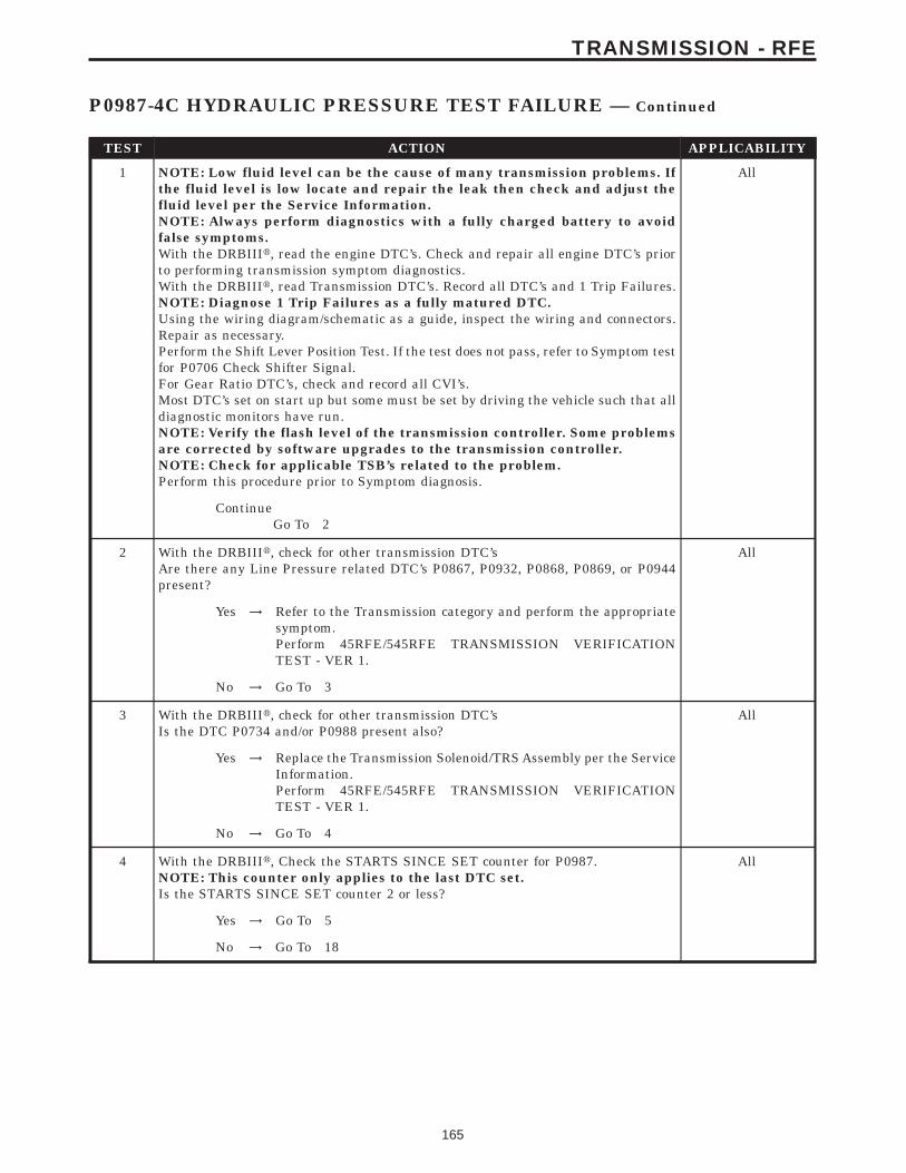
TEST ACTION APPLICABILITY
1 NOTE: Low fluid level can be the cause of many transmission problems. Ifthe fluid level is low locate and repair the leak then check and adjust thefluid level per the Service Information.NOTE: Always perform diagnostics with a fully charged battery to avoidfalse symptoms.With the DRBIIIt, read the engine DTC’s. Check and repair all engine DTC’s priorto performing transmission symptom diagnostics.With the DRBIIIt, read Transmission DTC’s. Record all DTC’s and 1 Trip Failures.NOTE: Diagnose 1 Trip Failures as a fully matured DTC.Using the wiring diagram/schematic as a guide, inspect the wiring and connectors.Repair as necessary.Perform the Shift Lever Position Test. If the test does not pass, refer to Symptom testfor P0706 Check Shifter Signal.For Gear Ratio DTC’s, check and record all CVI’s.Most DTC’s set on start up but some must be set by driving the vehicle such that alldiagnostic monitors have run.NOTE: Verify the flash level of the transmission controller. Some problemsare corrected by software upgrades to the transmission controller.NOTE: Check for applicable TSB’s related to the problem.Perform this procedure prior to Symptom diagnosis.
All
ContinueGo To 2
2 With the DRBIIIt, check for other transmission DTC’sAre there any Line Pressure related DTC’s P0867, P0932, P0868, P0869, or P0944present?
All
Yes → Refer to the Transmission category and perform the appropriatesymptom.Perform 45RFE/545RFE TRANSMISSION VERIFICATIONTEST - VER 1.
No → Go To 3
3 With the DRBIIIt, check for other transmission DTC’sIs the DTC P0734 and/or P0988 present also?
All
Yes → Replace the Transmission Solenoid/TRS Assembly per the ServiceInformation.Perform 45RFE/545RFE TRANSMISSION VERIFICATIONTEST - VER 1.
No → Go To 4
4 With the DRBIIIt, Check the STARTS SINCE SET counter for P0987.NOTE: This counter only applies to the last DTC set.Is the STARTS SINCE SET counter 2 or less?
All
Yes → Go To 5
No → Go To 18
165
TRANSMISSION - RFE
P0987-4C HYDRAULIC PRESSURE TEST FAILURE — Continued

TEST ACTION APPLICABILITY
5 Start the engine.Warm the transmission to 82° C or 180° F.With the DRBIIIt, monitor the Transmission Line Pressure.CAUTION: Firmly apply the brakes.With the brakes firmly applied, move the shift lever to each gear position and recordthe Transmission Line Pressure for each position.Allow the pressure to stabilize for at least 5 seconds in each range.Did the line pressure remain at a steady value between 586 and 655 Kpa or 85 and95 PSI?
All
Yes → Go To 6
No → Go To 10
6 Ignition on, engine not running.With the DRBIIIt in Sensors, monitor the Actual Line Pressure.While monitoring the Line Pressure, firmly push the Line Pressure Sensor harnessconnector towards the transmission.Did the Line Pressure change to about 207 kPa or 30 PSI when the harness connectorwas pushed?
All
Yes → Disconnect and properly reconnect the Line Pressure Sensorconnector. Inspect terminals and repair as necessary.Perform 45RFE/545RFE TRANSMISSION VERIFICATIONTEST - VER 1.
No → Go To 7
7 Turn the ignition off to the lock position.Remove the Starter Relay from the PDC.NOTE: Failure to remove the Starter Relay can cause a Transmission - NoResponse condition.Install the Transmission Simulator, Miller tool #8333.With the Transmission Simulator on the Input/Output Speed switch select the OFFposition.NOTE: All three DRBIIIt Line Pressure readings should be steady and ± 2.0PSI of the reading specified on the Transmission Simulator.Ignition on, engine not running.With the DRBIIIt, monitor the Line Pressure during the following step.Using the Transmission Simulator, turn the selector switch to each of the 3 LinePressure positions.Did the Line Pressure remain steady in all three positions?
All
Yes → Replace the Line Pressure Sensor per the Service Information.Perform 45RFE/545RFE TRANSMISSION VERIFICATIONTEST - VER 1.
No → Go To 8
166
TRANSMISSION - RFE
P0987-4C HYDRAULIC PRESSURE TEST FAILURE — Continued
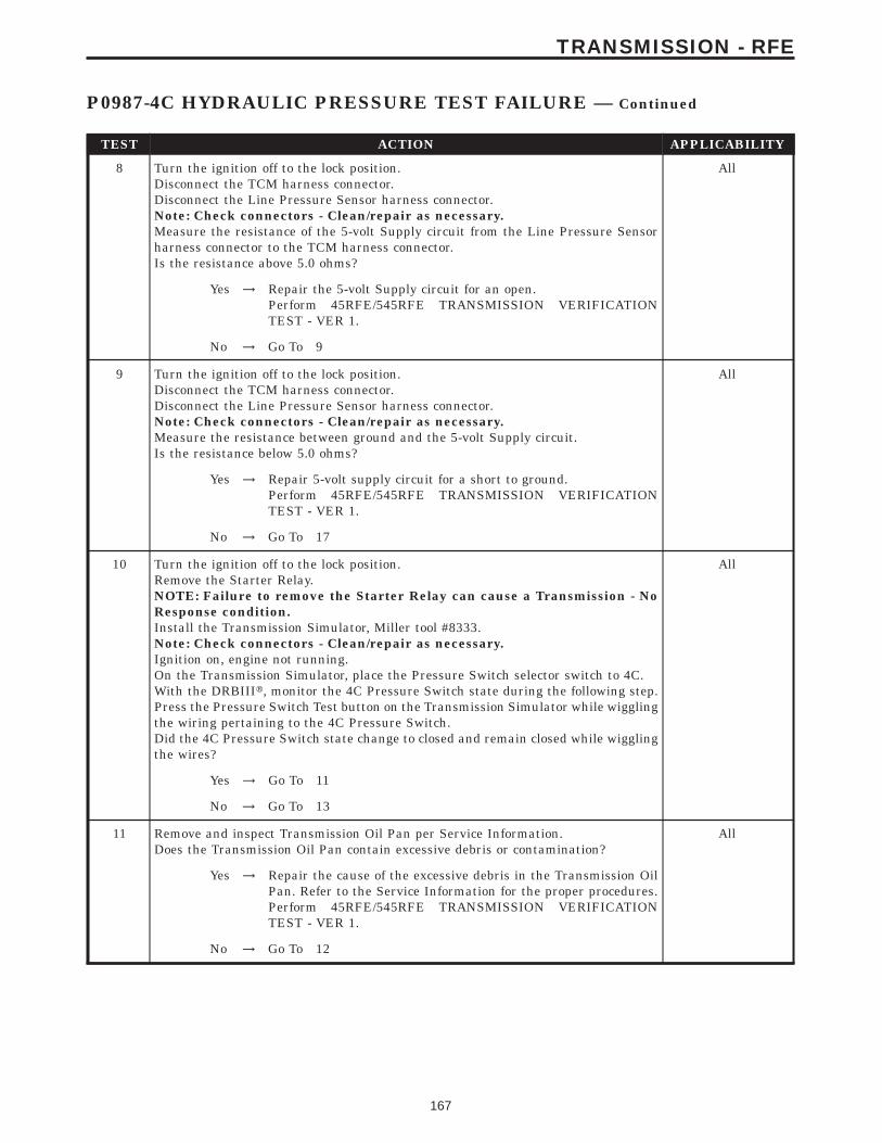
TEST ACTION APPLICABILITY
8 Turn the ignition off to the lock position.Disconnect the TCM harness connector.Disconnect the Line Pressure Sensor harness connector.Note: Check connectors - Clean/repair as necessary.Measure the resistance of the 5-volt Supply circuit from the Line Pressure Sensorharness connector to the TCM harness connector.Is the resistance above 5.0 ohms?
All
Yes → Repair the 5-volt Supply circuit for an open.Perform 45RFE/545RFE TRANSMISSION VERIFICATIONTEST - VER 1.
No → Go To 9
9 Turn the ignition off to the lock position.Disconnect the TCM harness connector.Disconnect the Line Pressure Sensor harness connector.Note: Check connectors - Clean/repair as necessary.Measure the resistance between ground and the 5-volt Supply circuit.Is the resistance below 5.0 ohms?
All
Yes → Repair 5-volt supply circuit for a short to ground.Perform 45RFE/545RFE TRANSMISSION VERIFICATIONTEST - VER 1.
No → Go To 17
10 Turn the ignition off to the lock position.Remove the Starter Relay.NOTE: Failure to remove the Starter Relay can cause a Transmission - NoResponse condition.Install the Transmission Simulator, Miller tool #8333.Note: Check connectors - Clean/repair as necessary.Ignition on, engine not running.On the Transmission Simulator, place the Pressure Switch selector switch to 4C.With the DRBIIIt, monitor the 4C Pressure Switch state during the following step.Press the Pressure Switch Test button on the Transmission Simulator while wigglingthe wiring pertaining to the 4C Pressure Switch.Did the 4C Pressure Switch state change to closed and remain closed while wigglingthe wires?
All
Yes → Go To 11
No → Go To 13
11 Remove and inspect Transmission Oil Pan per Service Information.Does the Transmission Oil Pan contain excessive debris or contamination?
All
Yes → Repair the cause of the excessive debris in the Transmission OilPan. Refer to the Service Information for the proper procedures.Perform 45RFE/545RFE TRANSMISSION VERIFICATIONTEST - VER 1.
No → Go To 12
167
TRANSMISSION - RFE
P0987-4C HYDRAULIC PRESSURE TEST FAILURE — Continued
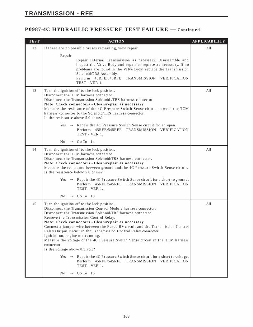
TEST ACTION APPLICABILITY
12 If there are no possible causes remaining, view repair. All
RepairRepair Internal Transmission as necessary. Disassemble andinspect the Valve Body and repair or replace as necessary. If noproblems are found in the Valve Body, replace the TransmissionSolenoid/TRS Assembly.Perform 45RFE/545RFE TRANSMISSION VERIFICATIONTEST - VER 1.
13 Turn the ignition off to the lock position.Disconnect the TCM harness connector.Disconnect the Transmission Solenoid /TRS harness connectorNote: Check connectors - Clean/repair as necessary.Measure the resistance of the 4C Pressure Switch Sense circuit between the TCMharness connector to the Solenoid/TRS harness connector.Is the resistance above 5.0 ohms?
All
Yes → Repair the 4C Pressure Switch Sense circuit for an open.Perform 45RFE/545RFE TRANSMISSION VERIFICATIONTEST - VER 1.
No → Go To 14
14 Turn the ignition off to the lock position.Disconnect the TCM harness connector.Disconnect the Transmission Solenoid/TRS harness connector.Note: Check connectors - Clean/repair as necessary.Measure the resistance between ground and the 4C Pressure Switch Sense circuit.Is the resistance below 5.0 ohms?
All
Yes → Repair the 4C Pressure Switch Sense circuit for a short to ground.Perform 45RFE/545RFE TRANSMISSION VERIFICATIONTEST - VER 1.
No → Go To 15
15 Turn the ignition off to the lock position.Disconnect the Transmission Control Module harness connector.Disconnect the Transmission Solenoid/TRS harness connector.Remove the Transmission Control Relay.Note: Check connectors - Clean/repair as necessary.Connect a jumper wire between the Fused B+ circuit and the Transmission ControlRelay Output circuit in the Transmission Control Relay connector.Ignition on, engine not running.Measure the voltage of the 4C Pressure Switch Sense circuit in the TCM harnessconnector.Is the voltage above 0.5 volt?
All
Yes → Repair the 4C Pressure Switch Sense circuit for a short to voltage.Perform 45RFE/545RFE TRANSMISSION VERIFICATIONTEST - VER 1.
No → Go To 16
168
TRANSMISSION - RFE
P0987-4C HYDRAULIC PRESSURE TEST FAILURE — Continued

TEST ACTION APPLICABILITY
16 Turn the ignition off to the lock position.Disconnect the Transmission Solenoid/TRS harness connector.Remove the Transmission Control Relay.Connect a jumper wire between the Fused B+ circuit and the Transmission ControlRelay Output circuit in the Transmission Control Relay connector.Ignition on, engine not running.Using a 12-volt test light connected to ground, check the Transmission Control RelayOutput circuit in the Solenoid/TRS harness connector.NOTE: The test light must illuminate brightly. Compare the brightness tothat of a direct connection to the battery.Does the test light illuminate brightly?
All
Yes → Go To 17
No → Repair the Transmission Control Relay Output circuit for anopen. If the fuse is open make sure to check for a short to ground.Perform 45RFE/545RFE TRANSMISSION VERIFICATIONTEST - VER 1.
17 Using the schematics as a guide, inspect the wiring and connectors. Repair asnecessary. Pay particular attention to all power and ground circuits.If there are no possible causes remaining, view repair.
All
RepairReplace the Transmission Control Module per the Service Infor-mation. WITH THE DRBIIIt PERFORM QUICK LEARNPerform 45RFE/545RFE TRANSMISSION VERIFICATIONTEST - VER 1.
18 The conditions necessary to set this DTC are not present at this time.Using the schematics as a guide, inspect the wiring and connectors specific to thiscircuit.Wiggle the wires while checking for shorts and open circuits.With the DRBIIIt, check the EATX DTC EVENT DATA to help identify theconditions in which the DTC was set.Were there any problems found?
All
Yes → Repair as necessary.Perform 45RFE/545RFE TRANSMISSION VERIFICATIONTEST - VER 1.
No → Test Complete.
169
TRANSMISSION - RFE
P0987-4C HYDRAULIC PRESSURE TEST FAILURE — Continued
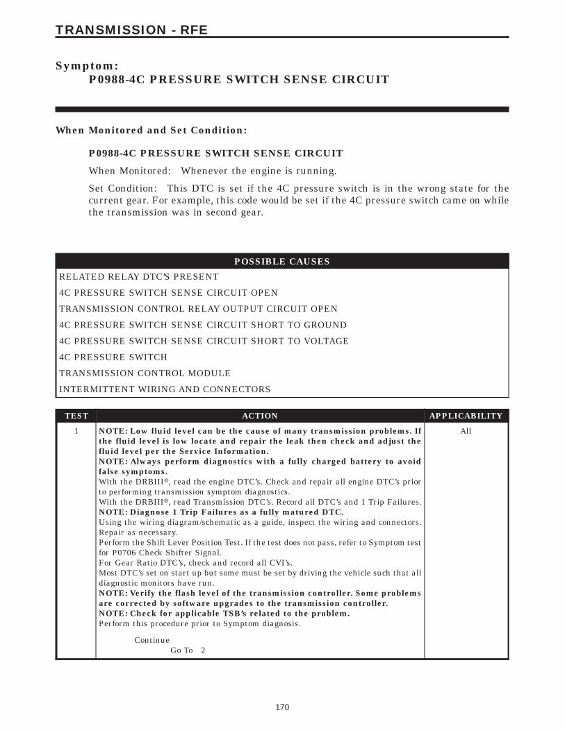
Symptom:P0988-4C PRESSURE SWITCH SENSE CIRCUIT
When Monitored and Set Condition:
P0988-4C PRESSURE SWITCH SENSE CIRCUIT
When Monitored: Whenever the engine is running.
Set Condition: This DTC is set if the 4C pressure switch is in the wrong state for thecurrent gear. For example, this code would be set if the 4C pressure switch came on whilethe transmission was in second gear.
POSSIBLE CAUSES
RELATED RELAY DTC’S PRESENT
4C PRESSURE SWITCH SENSE CIRCUIT OPEN
TRANSMISSION CONTROL RELAY OUTPUT CIRCUIT OPEN
4C PRESSURE SWITCH SENSE CIRCUIT SHORT TO GROUND
4C PRESSURE SWITCH SENSE CIRCUIT SHORT TO VOLTAGE
4C PRESSURE SWITCH
TRANSMISSION CONTROL MODULE
INTERMITTENT WIRING AND CONNECTORS
TEST ACTION APPLICABILITY
1 NOTE: Low fluid level can be the cause of many transmission problems. Ifthe fluid level is low locate and repair the leak then check and adjust thefluid level per the Service Information.NOTE: Always perform diagnostics with a fully charged battery to avoidfalse symptoms.With the DRBIIIt, read the engine DTC’s. Check and repair all engine DTC’s priorto performing transmission symptom diagnostics.With the DRBIIIt, read Transmission DTC’s. Record all DTC’s and 1 Trip Failures.NOTE: Diagnose 1 Trip Failures as a fully matured DTC.Using the wiring diagram/schematic as a guide, inspect the wiring and connectors.Repair as necessary.Perform the Shift Lever Position Test. If the test does not pass, refer to Symptom testfor P0706 Check Shifter Signal.For Gear Ratio DTC’s, check and record all CVI’s.Most DTC’s set on start up but some must be set by driving the vehicle such that alldiagnostic monitors have run.NOTE: Verify the flash level of the transmission controller. Some problemsare corrected by software upgrades to the transmission controller.NOTE: Check for applicable TSB’s related to the problem.Perform this procedure prior to Symptom diagnosis.
All
ContinueGo To 2
170
TRANSMISSION - RFE
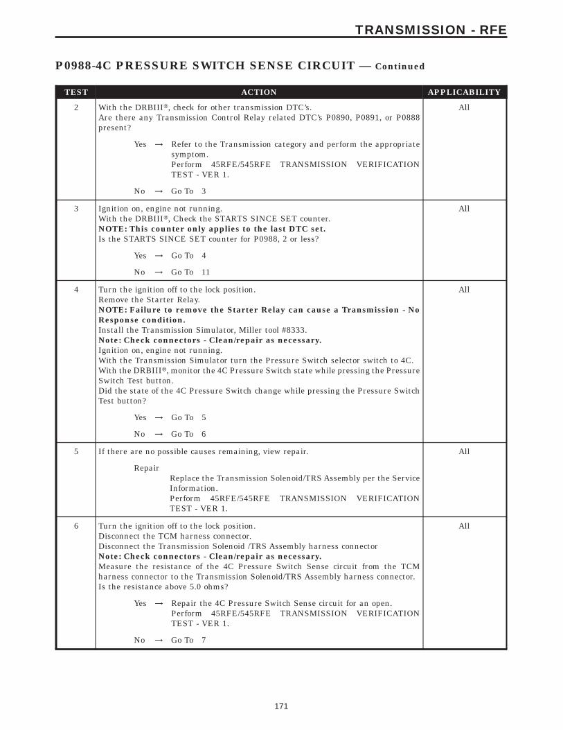
TEST ACTION APPLICABILITY
2 With the DRBIIIt, check for other transmission DTC’s.Are there any Transmission Control Relay related DTC’s P0890, P0891, or P0888present?
All
Yes → Refer to the Transmission category and perform the appropriatesymptom.Perform 45RFE/545RFE TRANSMISSION VERIFICATIONTEST - VER 1.
No → Go To 3
3 Ignition on, engine not running.With the DRBIIIt, Check the STARTS SINCE SET counter.NOTE: This counter only applies to the last DTC set.Is the STARTS SINCE SET counter for P0988, 2 or less?
All
Yes → Go To 4
No → Go To 11
4 Turn the ignition off to the lock position.Remove the Starter Relay.NOTE: Failure to remove the Starter Relay can cause a Transmission - NoResponse condition.Install the Transmission Simulator, Miller tool #8333.Note: Check connectors - Clean/repair as necessary.Ignition on, engine not running.With the Transmission Simulator turn the Pressure Switch selector switch to 4C.With the DRBIIIt, monitor the 4C Pressure Switch state while pressing the PressureSwitch Test button.Did the state of the 4C Pressure Switch change while pressing the Pressure SwitchTest button?
All
Yes → Go To 5
No → Go To 6
5 If there are no possible causes remaining, view repair. All
RepairReplace the Transmission Solenoid/TRS Assembly per the ServiceInformation.Perform 45RFE/545RFE TRANSMISSION VERIFICATIONTEST - VER 1.
6 Turn the ignition off to the lock position.Disconnect the TCM harness connector.Disconnect the Transmission Solenoid /TRS Assembly harness connectorNote: Check connectors - Clean/repair as necessary.Measure the resistance of the 4C Pressure Switch Sense circuit from the TCMharness connector to the Transmission Solenoid/TRS Assembly harness connector.Is the resistance above 5.0 ohms?
All
Yes → Repair the 4C Pressure Switch Sense circuit for an open.Perform 45RFE/545RFE TRANSMISSION VERIFICATIONTEST - VER 1.
No → Go To 7
171
TRANSMISSION - RFE
P0988-4C PRESSURE SWITCH SENSE CIRCUIT — Continued
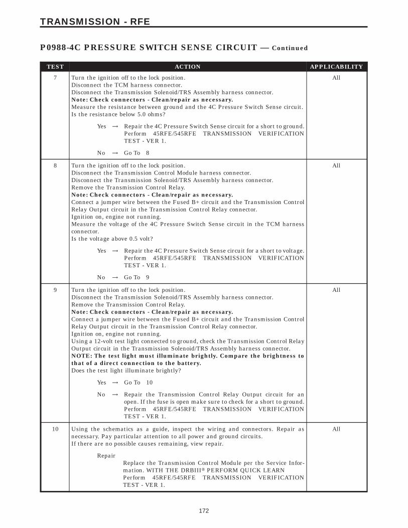
TEST ACTION APPLICABILITY
7 Turn the ignition off to the lock position.Disconnect the TCM harness connector.Disconnect the Transmission Solenoid/TRS Assembly harness connector.Note: Check connectors - Clean/repair as necessary.Measure the resistance between ground and the 4C Pressure Switch Sense circuit.Is the resistance below 5.0 ohms?
All
Yes → Repair the 4C Pressure Switch Sense circuit for a short to ground.Perform 45RFE/545RFE TRANSMISSION VERIFICATIONTEST - VER 1.
No → Go To 8
8 Turn the ignition off to the lock position.Disconnect the Transmission Control Module harness connector.Disconnect the Transmission Solenoid/TRS Assembly harness connector.Remove the Transmission Control Relay.Note: Check connectors - Clean/repair as necessary.Connect a jumper wire between the Fused B+ circuit and the Transmission ControlRelay Output circuit in the Transmission Control Relay connector.Ignition on, engine not running.Measure the voltage of the 4C Pressure Switch Sense circuit in the TCM harnessconnector.Is the voltage above 0.5 volt?
All
Yes → Repair the 4C Pressure Switch Sense circuit for a short to voltage.Perform 45RFE/545RFE TRANSMISSION VERIFICATIONTEST - VER 1.
No → Go To 9
9 Turn the ignition off to the lock position.Disconnect the Transmission Solenoid/TRS Assembly harness connector.Remove the Transmission Control Relay.Note: Check connectors - Clean/repair as necessary.Connect a jumper wire between the Fused B+ circuit and the Transmission ControlRelay Output circuit in the Transmission Control Relay connector.Ignition on, engine not running.Using a 12-volt test light connected to ground, check the Transmission Control RelayOutput circuit in the Transmission Solenoid/TRS Assembly harness connector.NOTE: The test light must illuminate brightly. Compare the brightness tothat of a direct connection to the battery.Does the test light illuminate brightly?
All
Yes → Go To 10
No → Repair the Transmission Control Relay Output circuit for anopen. If the fuse is open make sure to check for a short to ground.Perform 45RFE/545RFE TRANSMISSION VERIFICATIONTEST - VER 1.
10 Using the schematics as a guide, inspect the wiring and connectors. Repair asnecessary. Pay particular attention to all power and ground circuits.If there are no possible causes remaining, view repair.
All
RepairReplace the Transmission Control Module per the Service Infor-mation. WITH THE DRBIIIt PERFORM QUICK LEARNPerform 45RFE/545RFE TRANSMISSION VERIFICATIONTEST - VER 1.
172
TRANSMISSION - RFE
P0988-4C PRESSURE SWITCH SENSE CIRCUIT — Continued

TEST ACTION APPLICABILITY
11 The conditions necessary to set this DTC are not present at this time.Using the schematics as a guide, inspect the wiring and connectors specific to thiscircuit.Wiggle the wires while checking for shorts and open circuits.Check for a Primary Oil filter installed incorrectly.A dislodged Reverse Carrier Snap Ring will typically set this DTC on heavy throttleacceleration from a dead stop.With the DRBIIIt, check the EATX DTC EVENT DATA to help identify theconditions in which the DTC was set.Were there any problems found?
All
Yes → Repair as necessary.Perform 45RFE/545RFE TRANSMISSION VERIFICATIONTEST - VER 1.
No → Test Complete.
173
TRANSMISSION - RFE
P0988-4C PRESSURE SWITCH SENSE CIRCUIT — Continued

Symptom:P1684-BATTERY WAS DISCONNECTED
When Monitored and Set Condition:
P1684-BATTERY WAS DISCONNECTED
When Monitored: Whenever the ignition is in the Run/Start position.
Set Condition: This DTC is set whenever the Transmission Control Module is discon-nected from battery power (Fused B+) and/or ground. It will also be set during a DRBIIItBattery Disconnect procedure and/or a Quick Learn procedure.
POSSIBLE CAUSES
BATTERY WAS DISCONNECTED
DRBIIIt BATTERY DISCONNECT PERFORMED
QUICK LEARN WAS PERFORMED
TCM WAS REPLACED OR DISCONNECTED
INTERMITTENT WIRING AND CONNECTORS
TEST ACTION APPLICABILITY
1 NOTE: Low fluid level can be the cause of many transmission problems. Ifthe fluid level is low locate and repair the leak then check and adjust thefluid level per the Service Information.NOTE: Always perform diagnostics with a fully charged battery to avoidfalse symptoms.With the DRBIIIt, read the engine DTC’s. Check and repair all engine DTC’s priorto performing transmission symptom diagnostics.With the DRBIIIt, read Transmission DTC’s. Record all DTC’s and 1 Trip Failures.NOTE: Diagnose 1 Trip Failures as a fully matured DTC.Using the wiring diagram/schematic as a guide, inspect the wiring and connectors.Repair as necessary.Perform the Shift Lever Position Test. If the test does not pass, refer to Symptom testfor P0706 Check Shifter Signal.For Gear Ratio DTC’s, check and record all CVI’s.Most DTC’s set on start up but some must be set by driving the vehicle such that alldiagnostic monitors have run.NOTE: Verify the flash level of the transmission controller. Some problemsare corrected by software upgrades to the transmission controller.NOTE: Check for applicable TSB’s related to the problem.Perform this procedure prior to Symptom diagnosis.
All
ContinueGo To 2
2 This DTC is an informational DTC only.This DTC is set due to a momentary loss of the Fused B+ and/or ground to the TCM.Continue to view the possible causes for this DTC.
All
ContinueGo To 3
174
TRANSMISSION - RFE
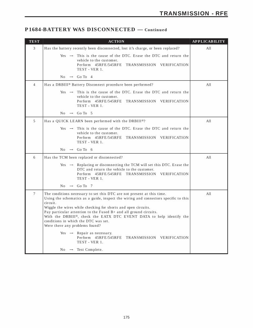
TEST ACTION APPLICABILITY
3 Has the battery recently been disconnected, lost it’s charge, or been replaced? All
Yes → This is the cause of the DTC. Erase the DTC and return thevehicle to the customer.Perform 45RFE/545RFE TRANSMISSION VERIFICATIONTEST - VER 1.
No → Go To 4
4 Has a DRBIIIt Battery Disconnect procedure been performed? All
Yes → This is the cause of the DTC. Erase the DTC and return thevehicle to the customer.Perform 45RFE/545RFE TRANSMISSION VERIFICATIONTEST - VER 1.
No → Go To 5
5 Has a QUICK LEARN been performed with the DRBIIIt? All
Yes → This is the cause of the DTC. Erase the DTC and return thevehicle to the customer.Perform 45RFE/545RFE TRANSMISSION VERIFICATIONTEST - VER 1.
No → Go To 6
6 Has the TCM been replaced or disconnected? All
Yes → Replacing or disconnecting the TCM will set this DTC. Erase theDTC and return the vehicle to the customer.Perform 45RFE/545RFE TRANSMISSION VERIFICATIONTEST - VER 1.
No → Go To 7
7 The conditions necessary to set this DTC are not present at this time.Using the schematics as a guide, inspect the wiring and connectors specific to thiscircuit.Wiggle the wires while checking for shorts and open circuits.Pay particular attention to the Fused B+ and all ground circuits.With the DRBIIIt, check the EATX DTC EVENT DATA to help identify theconditions in which the DTC was set.Were there any problems found?
All
Yes → Repair as necessary.Perform 45RFE/545RFE TRANSMISSION VERIFICATIONTEST - VER 1.
No → Test Complete.
175
TRANSMISSION - RFE
P1684-BATTERY WAS DISCONNECTED — Continued
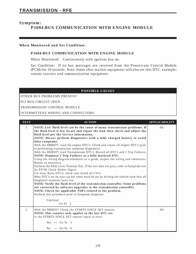
Symptom:P1694-BUS COMMUNICATION WITH ENGINE MODULE
When Monitored and Set Condition:
P1694-BUS COMMUNICATION WITH ENGINE MODULE
When Monitored: Continuously with ignition key on.
Set Condition: If no bus messages are received from the Powertrain Control Module(PCM) for 10 seconds. Note: Some after market equipment will also set this DTC. example:remote starters and communication equipment.
POSSIBLE CAUSES
OTHER BUS PROBLEMS PRESENT
PCI BUS CIRCUIT OPEN
TRANSMISSION CONTROL MODULE
INTERMITTENT WIRING AND CONNECTORS
TEST ACTION APPLICABILITY
1 NOTE: Low fluid level can be the cause of many transmission problems. Ifthe fluid level is low locate and repair the leak then check and adjust thefluid level per the Service Information.NOTE: Always perform diagnostics with a fully charged battery to avoidfalse symptoms.With the DRBIIIt, read the engine DTC’s. Check and repair all engine DTC’s priorto performing transmission symptom diagnostics.With the DRBIIIt, read Transmission DTC’s. Record all DTC’s and 1 Trip Failures.NOTE: Diagnose 1 Trip Failures as a fully matured DTC.Using the wiring diagram/schematic as a guide, inspect the wiring and connectors.Repair as necessary.Perform the Shift Lever Position Test. If the test does not pass, refer to Symptom testfor P0706 Check Shifter Signal.For Gear Ratio DTC’s, check and record all CVI’s.Most DTC’s set on start up but some must be set by driving the vehicle such that alldiagnostic monitors have run.NOTE: Verify the flash level of the transmission controller. Some problemsare corrected by software upgrades to the transmission controller.NOTE: Check for applicable TSB’s related to the problem.Perform this procedure prior to Symptom diagnosis.
All
ContinueGo To 2
2 With the DRBIIIt, Check the STARTS SINCE SET counter.NOTE: This counter only applies to the last DTC set.Is the STARTS SINCE SET counter equal to zero?
All
Yes → Go To 3
No → Go To 6
176
TRANSMISSION - RFE

TEST ACTION APPLICABILITY
3 With the DRBIIIt, attempt to communicate with other modules on the vehicle, checkfor evidence of a vehicle bus problem.Bus related DTC’s in other modules point to an overall vehicle bus problem. Othersymptoms such as a customer complaint of intermittent operation of bus controlledfeatures also indicate a bus problem.Does the PRNDL display indicate 9No Bus9 or is there any evidence of an overallvehicle bus problem?
All
Yes → Refer to the Communication Category and perform the appropri-ate symptom.Perform 45RFE/545RFE TRANSMISSION VERIFICATIONTEST - VER 1.
No → Go To 4
4 Turn the ignition off to the lock position.Disconnect the PCM harness connectors.Note: Check connectors - Clean/repair as necessary.Measure the resistance of the PCI Bus circuit from the PCM harness connector to theData Link Connector.NOTE: CAREFULLY PROBE THE DLC. DAMAGE TO THE DLC TERMI-NALS WILL RESULT IN POOR TERMINAL TO PIN CONNECTION.Is the resistance above 5.0 ohms?
All
Yes → Repair the open PCI Bus circuit between the PCM and the DataLink Connector.Perform 45RFE/545RFE TRANSMISSION VERIFICATIONTEST - VER 1.
No → Go To 5
5 Using the schematics as a guide, inspect the wiring and connectors. Repair asnecessary. Pay particular attention to all power and ground circuits.If there are no possible causes remaining, view repair.
All
RepairReplace the Transmission Control Module per the Service Infor-mation. WITH THE DRBIIIt PERFORM QUICK LEARN.Perform 45RFE/545RFE TRANSMISSION VERIFICATIONTEST - VER 1.
6 The conditions necessary to set this DTC are not present at this time.Using the schematics as a guide, inspect the wiring and connectors specific to thiscircuit.Wiggle the wires while checking for shorts and open circuits.With the DRBIIIt, check the EATX DTC EVENT DATA to help identify theconditions in which the DTC was set.Were there any problems found?
All
Yes → Repair as necessary. Note: Some after market equipment will setthis DTC.Perform 45RFE/545RFE TRANSMISSION VERIFICATIONTEST - VER 1.
No → Test Complete.
177
TRANSMISSION - RFE
P1694-BUS COMMUNICATION WITH ENGINE MODULE — Continued

Symptom:P1715-RESTRICTED PORT IN T3 RANGE
When Monitored and Set Condition:
P1715-RESTRICTED PORT IN T3 RANGE
When Monitored: Whenever the PRNDL code indicates Temp3.
Set Condition: This code sets whenever the conditions for a code P1776 (47) are satisfiedwith the shifter in the temp3 zone. This causes a restricted port.
POSSIBLE CAUSES
RELATED TRANSMISSION DTC’S PRESENT
CUSTOMER DRIVING HABITS
MISADJUSTED SHIFTER
TEST ACTION APPLICABILITY
1 NOTE: Low fluid level can be the cause of many transmission problems. Ifthe fluid level is low locate and repair the leak then check and adjust thefluid level per the Service Information.NOTE: Always perform diagnostics with a fully charged battery to avoidfalse symptoms.With the DRBIIIt, read the engine DTC’s. Check and repair all engine DTC’s priorto performing transmission symptom diagnostics.With the DRBIIIt, read Transmission DTC’s. Record all DTC’s and 1 Trip Failures.NOTE: Diagnose 1 Trip Failures as a fully matured DTC.Using the wiring diagram/schematic as a guide, inspect the wiring and connectors.Repair as necessary.Perform the Shift Lever Position Test. If the test does not pass, refer to Symptom testfor P0706 Check Shifter Signal.For Gear Ratio DTC’s, check and record all CVI’s.Most DTC’s set on start up but some must be set by driving the vehicle such that alldiagnostic monitors have run.NOTE: Verify the flash level of the transmission controller. Some problemsare corrected by software upgrades to the transmission controller.NOTE: Check for applicable TSB’s related to the problem.Perform this procedure prior to Symptom diagnosis.
All
ContinueGo To 2
2 With the DRBIIIt, check for other transmission DTC’sAre any of the following DTC’s P0731, P0732, P0733, P0734, P1736 or P0715present?
All
Yes → Refer to the Transmission category and perform the appropriatesymptom.Perform 45RFE/545RFE TRANSMISSION VERIFICATIONTEST - VER 1.
No → Go To 3
178
TRANSMISSION - RFE
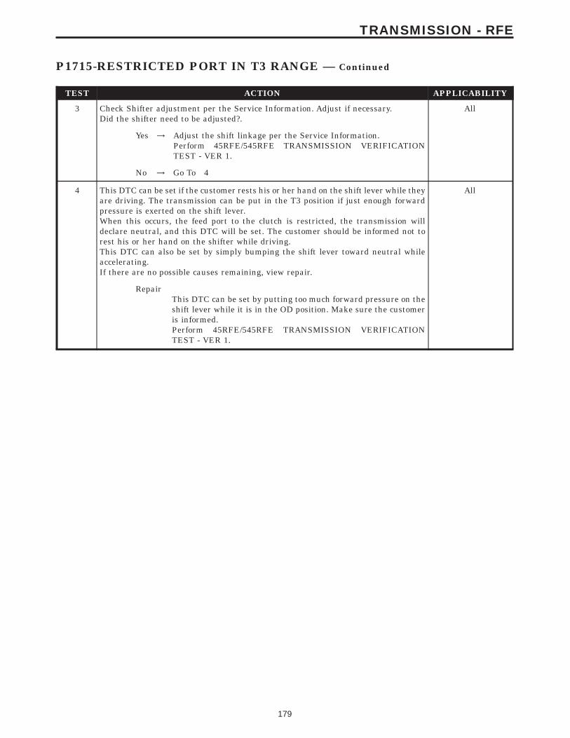
TEST ACTION APPLICABILITY
3 Check Shifter adjustment per the Service Information. Adjust if necessary.Did the shifter need to be adjusted?.
All
Yes → Adjust the shift linkage per the Service Information.Perform 45RFE/545RFE TRANSMISSION VERIFICATIONTEST - VER 1.
No → Go To 4
4 This DTC can be set if the customer rests his or her hand on the shift lever while theyare driving. The transmission can be put in the T3 position if just enough forwardpressure is exerted on the shift lever.When this occurs, the feed port to the clutch is restricted, the transmission willdeclare neutral, and this DTC will be set. The customer should be informed not torest his or her hand on the shifter while driving.This DTC can also be set by simply bumping the shift lever toward neutral whileaccelerating.If there are no possible causes remaining, view repair.
All
RepairThis DTC can be set by putting too much forward pressure on theshift lever while it is in the OD position. Make sure the customeris informed.Perform 45RFE/545RFE TRANSMISSION VERIFICATIONTEST - VER 1.
179
TRANSMISSION - RFE
P1715-RESTRICTED PORT IN T3 RANGE — Continued
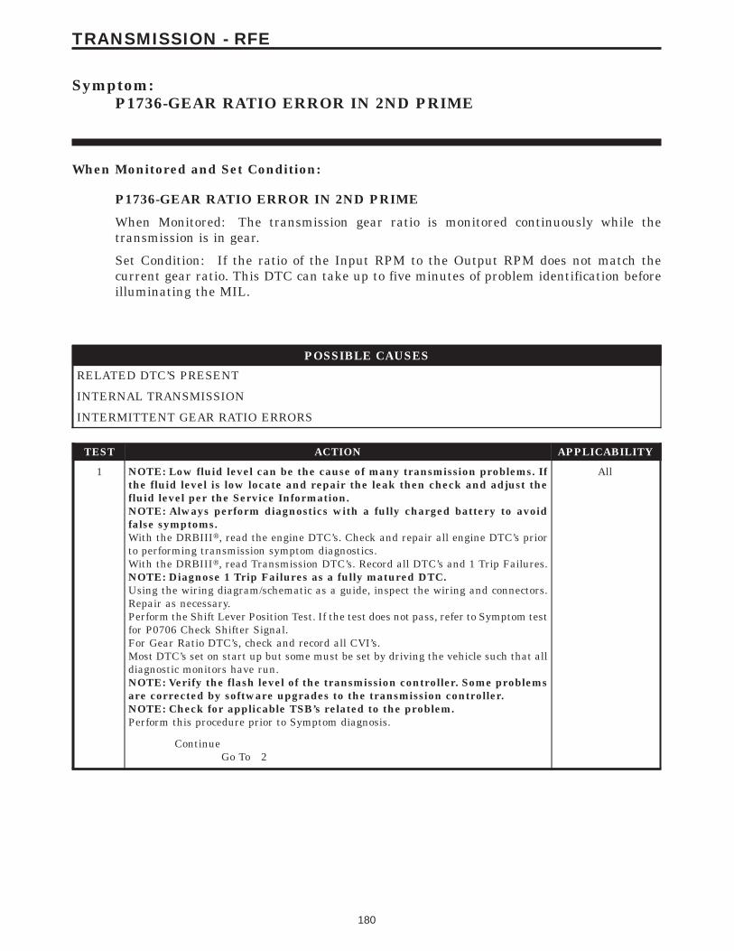
Symptom:P1736-GEAR RATIO ERROR IN 2ND PRIME
When Monitored and Set Condition:
P1736-GEAR RATIO ERROR IN 2ND PRIME
When Monitored: The transmission gear ratio is monitored continuously while thetransmission is in gear.
Set Condition: If the ratio of the Input RPM to the Output RPM does not match thecurrent gear ratio. This DTC can take up to five minutes of problem identification beforeilluminating the MIL.
POSSIBLE CAUSES
RELATED DTC’S PRESENT
INTERNAL TRANSMISSION
INTERMITTENT GEAR RATIO ERRORS
TEST ACTION APPLICABILITY
1 NOTE: Low fluid level can be the cause of many transmission problems. Ifthe fluid level is low locate and repair the leak then check and adjust thefluid level per the Service Information.NOTE: Always perform diagnostics with a fully charged battery to avoidfalse symptoms.With the DRBIIIt, read the engine DTC’s. Check and repair all engine DTC’s priorto performing transmission symptom diagnostics.With the DRBIIIt, read Transmission DTC’s. Record all DTC’s and 1 Trip Failures.NOTE: Diagnose 1 Trip Failures as a fully matured DTC.Using the wiring diagram/schematic as a guide, inspect the wiring and connectors.Repair as necessary.Perform the Shift Lever Position Test. If the test does not pass, refer to Symptom testfor P0706 Check Shifter Signal.For Gear Ratio DTC’s, check and record all CVI’s.Most DTC’s set on start up but some must be set by driving the vehicle such that alldiagnostic monitors have run.NOTE: Verify the flash level of the transmission controller. Some problemsare corrected by software upgrades to the transmission controller.NOTE: Check for applicable TSB’s related to the problem.Perform this procedure prior to Symptom diagnosis.
All
ContinueGo To 2
180
TRANSMISSION - RFE

TEST ACTION APPLICABILITY
2 With the DRBIIIt, check for other transmission DTC’sAre any of the DTC’s P0944, P0715, P0720, P1794, P0867, P0932, P0868, or P0869also present?
All
Yes → If any of these DTCs are present, they will cause a speed ratioerror. Refer to appropriate symptom in the Transmission category.Perform the test for P0944 first if it is present.Perform 45RFE/545RFE TRANSMISSION VERIFICATIONTEST - VER 1.
No → Go To 3
3 With the DRBIIIt, perform the 2nd prime Gear Clutch Test. Follow the instructionson the DRBIIIt.Increase the throttle angle, TPS Degree, to 30° for no more than a few seconds.CAUTION: Do not overheat the transmission.Did the clutch test pass, Input Speed remain at zero?
All
Yes → Go To 4
No → Go To 5
4 The conditions to set this DTC are not currently present.Check the gearshift linkage adjustment.Intermittent gear ratio DTCs can be set by problems in the Input and Output SpeedSensor circuits and/or Speed Sensor Ground circuit.Check the Speed Sensor wiring and connectors for good connection, then perform awiggle test using the Transmission Simulator, Miller tool # 8333.Gear ratio DTC’s can also be set under extreme temperature conditions, this isusually caused by an internal problem. Verify if the problem is only experiencedunder extreme hot or cold conditions.With the DRBIIIt, check the EATX DTC EVENT DATA to help identify theconditions in which the DTC was set.If there are no possible causes remaining, view repair.
All
RepairRepair as necessary. Refer to the Service information for theproper internal repair procedure.Perform 45RFE/545RFE TRANSMISSION VERIFICATIONTEST - VER 1.
5 If there are no possible causes remaining, view repair. All
RepairRepair transmission as necessary. If there were any line pressureDTC’s present along with this DTC, make sure to inspect thepump and Pressure Control Solenoid per the Service Information.Perform 45RFE/545RFE TRANSMISSION VERIFICATIONTEST - VER 1.
181
TRANSMISSION - RFE
P1736-GEAR RATIO ERROR IN 2ND PRIME — Continued

Symptom:P1775-SOLENOID SWITCH VALVE LATCHED IN TCC POSITION
When Monitored and Set Condition:
P1775-SOLENOID SWITCH VALVE LATCHED IN TCC POSITION
When Monitored: During an attempted shift into 1st gear.
Set Condition: This DTC is set if three unsuccessful attempts are made to get into 1stgear in one given ignition start. This DTC can take up to five minutes of problemidentification before illuminating the MIL.
POSSIBLE CAUSES
RELATED DTC P0841 PRESENT
LR PRESSURE SWITCH SENSE CIRCUIT OPEN
TRANSMISSION CONTROL RELAY OUTPUT CIRCUIT OPEN
LR PRESSURE SWITCH SENSE CIRCUIT SHORT TO GROUND
LR PRESSURE SWITCH SENSE CIRCUIT SHORT TO VOLTAGE
INTERNAL TRANSMISSION
TRANSMISSION CONTROL MODULE
INTERMITTENT WIRING AND CONNECTORS
TEST ACTION APPLICABILITY
1 NOTE: Low fluid level can be the cause of many transmission problems. Ifthe fluid level is low locate and repair the leak then check and adjust thefluid level per the Service Information.NOTE: Always perform diagnostics with a fully charged battery to avoidfalse symptoms.With the DRBIIIt, read the engine DTC’s. Check and repair all engine DTC’s priorto performing transmission symptom diagnostics.With the DRBIIIt, read Transmission DTC’s. Record all DTC’s and 1 Trip Failures.NOTE: Diagnose 1 Trip Failures as a fully matured DTC.Using the wiring diagram/schematic as a guide, inspect the wiring and connectors.Repair as necessary.Perform the Shift Lever Position Test. If the test does not pass, refer to Symptom testfor P0706 Check Shifter Signal.For Gear Ratio DTC’s, check and record all CVI’s.Most DTC’s set on start up but some must be set by driving the vehicle such that alldiagnostic monitors have run.NOTE: Verify the flash level of the transmission controller. Some problemsare corrected by software upgrades to the transmission controller.NOTE: Check for applicable TSB’s related to the problem.Perform this procedure prior to Symptom diagnosis.
All
ContinueGo To 2
182
TRANSMISSION - RFE

TEST ACTION APPLICABILITY
2 With the DRBIIIt, check for other transmission DTC’sIs the DTC P0841 present also?
All
Yes → Refer to the Transmission category and perform the appropriatesymptom.Perform 45RFE/545RFE TRANSMISSION VERIFICATIONTEST - VER 1.
No → Go To 3
3 With the DRBIIIt, Check the STARTS SINCE SET counter.NOTE: This counter only applies to the last DTC set.Is the STARTS SINCE SET counter for P1775 at 2 or less?
All
Yes → Go To 4
No → Go To 11
4 Turn the ignition off to the lock position.Remove the Starter Relay.NOTE: Failure to remove the Starter Relay can cause a Transmission - NoResponse condition.Install the Transmission Simulator, Miller tool #8333.Note: Check connectors - Clean/repair as necessary.Ignition on, engine not running.With the Transmission Simulator, turn the Pressure Switch selector switch to LR.With the DRBIIIt, monitor the LR Pressure Switch state while pressing the PressureSwitch Test button on the Transmission Simulator.Did the state of the UD Pressure Switch change while pressing the Pressure SwitchTest button?
All
Yes → Go To 5
No → Go To 6
5 If there are no possible causes remaining, view repair. All
RepairRepair internal transmission as necessary. Inspect the SolenoidSwitch Valve per the Service Information and repair or replace asnecessary. If no problems are found, replace the TransmissionSolenoid/TRS Assembly.Perform 45RFE/545RFE TRANSMISSION VERIFICATIONTEST - VER 1.
6 Turn the ignition off to the lock position.Disconnect the TCM harness connector.Disconnect the Transmission Solenoid /TRS Assembly harness connectorNote: Check connectors - Clean/repair as necessary.Measure the resistance of the LR Pressure Switch Sense circuit from the TCMharness connector to the Solenoid/TRS Assembly harness connector.Is the resistance above 5.0 ohms?
All
Yes → Repair the LR Pressure Switch Sense circuit for an open.Perform 45RFE/545RFE TRANSMISSION VERIFICATIONTEST - VER 1.
No → Go To 7
183
TRANSMISSION - RFE
P1775-SOLENOID SWITCH VALVE LATCHED IN TCC POSITION —Continued

TEST ACTION APPLICABILITY
7 Turn the ignition off to the lock position.Disconnect the TCM harness connector.Disconnect the Transmission Solenoid/TRS Assembly harness connector.Note: Check connectors - Clean/repair as necessary.Measure the resistance between ground and the LR Pressure Switch Sense circuit.Is the resistance below 5.0 ohms?
All
Yes → Repair the LR Pressure Switch Sense circuit for a short to ground.Perform 45RFE/545RFE TRANSMISSION VERIFICATIONTEST - VER 1.
No → Go To 8
8 Turn the ignition off to the lock position.Disconnect the TCM harness connector.Remove the Transmission Control Relay.Note: Check connectors - Clean/repair as necessary.Connect a jumper wire between the Fused B+ circuit and the Transmission ControlRelay Output circuit in the Transmission Control Relay connector.Ignition on, engine not running.Measure the voltage of the LR Pressure Switch Sense circuit in the TCM harnessconnector.Is the voltage above 0.5 volts?
All
Yes → Repair the LR Pressure Switch Sense circuit for a short to voltage.Perform 45RFE/545RFE TRANSMISSION VERIFICATIONTEST - VER 1.
No → Go To 9
9 Turn the ignition off to the lock position.Disconnect the Transmission Solenoid/TRS Assembly harness connector.Remove the Transmission Control Relay.Note: Check connectors - Clean/repair as necessary.Connect a jumper wire between the Fused B+ circuit and the Transmission ControlRelay Output circuit in the Transmission Control Relay connector.Ignition on, engine not running.Using a 12-volt test light connected to ground, check the Transmission Control RelayOutput circuit in the Solenoid/TRS harness connector.NOTE: The test light must illuminate brightly. Compare the brightness tothat of a direct connection to the battery.Does the test light illuminate brightly?
All
Yes → Go To 10
No → Repair the Transmission Control Relay Output circuit for an openor high resistance. If the fuse is open make sure to check for ashort to ground.Perform 45RFE/545RFE TRANSMISSION VERIFICATIONTEST - VER 1.
10 Using the schematics as a guide, inspect the wiring and connectors. Repair asnecessary. Pay particular attention to all power and ground circuits.If there are no possible causes remaining, view repair.
All
RepairReplace the Transmission Control Module per the Service Infor-mation. WITH THE DRBIIIt PERFORM QUICK LEARNPerform 45RFE/545RFE TRANSMISSION VERIFICATIONTEST - VER 1.
184
TRANSMISSION - RFE
P1775-SOLENOID SWITCH VALVE LATCHED IN TCC POSITION —Continued
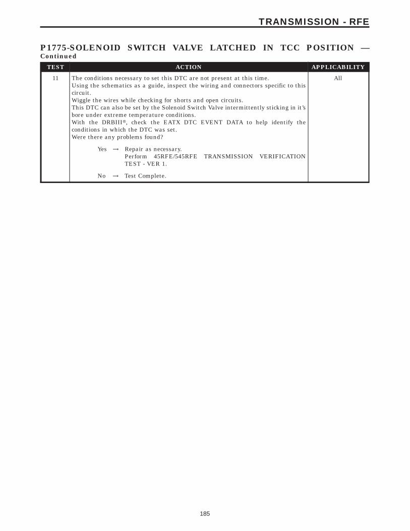
TEST ACTION APPLICABILITY
11 The conditions necessary to set this DTC are not present at this time.Using the schematics as a guide, inspect the wiring and connectors specific to thiscircuit.Wiggle the wires while checking for shorts and open circuits.This DTC can also be set by the Solenoid Switch Valve intermittently sticking in it’sbore under extreme temperature conditions.With the DRBIIIt, check the EATX DTC EVENT DATA to help identify theconditions in which the DTC was set.Were there any problems found?
All
Yes → Repair as necessary.Perform 45RFE/545RFE TRANSMISSION VERIFICATIONTEST - VER 1.
No → Test Complete.
185
TRANSMISSION - RFE
P1775-SOLENOID SWITCH VALVE LATCHED IN TCC POSITION —Continued

Symptom:P1776-SOLENOID SWITCH VALVE LATCHED IN LR POSITION
When Monitored and Set Condition:
P1776-SOLENOID SWITCH VALVE LATCHED IN LR POSITION
When Monitored: Continuously when doing partial or full EMCC - PEMCC or FEMCC.
Set Condition: If the transmission senses the L/R Pressure Switch closing while perform-ing PEMCC or FEMCC. This DTC will set after two unsuccessful attempts to performPEMCC or FEMCC and can take up to five minutes of problem identification beforeilluminating the MIL.
POSSIBLE CAUSES
RELATED DTC P0841 PRESENT
LR PRESSURE SWITCH SENSE CIRCUIT OPEN
TRANSMISSION CONTROL RELAY OUTPUT CIRCUIT OPEN
LR PRESSURE SWITCH SENSE CIRCUIT SHORT TO GROUND
LR PRESSURE SWITCH SENSE CIRCUIT SHORT TO VOLTAGE
INTERNAL TRANSMISSION
TRANSMISSION CONTROL MODULE
INTERMITTENT WIRING AND CONNECTORS
TEST ACTION APPLICABILITY
1 NOTE: Low fluid level can be the cause of many transmission problems. Ifthe fluid level is low locate and repair the leak then check and adjust thefluid level per the Service Information.NOTE: Always perform diagnostics with a fully charged battery to avoidfalse symptoms.With the DRBIIIt, read the engine DTC’s. Check and repair all engine DTC’s priorto performing transmission symptom diagnostics.With the DRBIIIt, read Transmission DTC’s. Record all DTC’s and 1 Trip Failures.NOTE: Diagnose 1 Trip Failures as a fully matured DTC.Using the wiring diagram/schematic as a guide, inspect the wiring and connectors.Repair as necessary.Perform the Shift Lever Position Test. If the test does not pass, refer to Symptom testfor P0706 Check Shifter Signal.For Gear Ratio DTC’s, check and record all CVI’s.Most DTC’s set on start up but some must be set by driving the vehicle such that alldiagnostic monitors have run.NOTE: Verify the flash level of the transmission controller. Some problemsare corrected by software upgrades to the transmission controller.NOTE: Check for applicable TSB’s related to the problem.Perform this procedure prior to Symptom diagnosis.
All
ContinueGo To 2
186
TRANSMISSION - RFE

TEST ACTION APPLICABILITY
2 With the DRBIIIt, check for other transmission DTC’sIs the DTC P0841 present also?
All
Yes → Refer to symptom list and perform the appropriate symptom.Perform 45RFE/545RFE TRANSMISSION VERIFICATIONTEST - VER 1.
No → Go To 3
3 Perform a visual inspection of all connectors, wiring, and cooler connections beforeproceeding. Repair as necessary.With the DRBIIIt, Check the STARTS SINCE SET counter.NOTE: This counter only applies to the last DTC set.Is the STARTS SINCE SET counter 2 or less?
All
Yes → Go To 4
No → Go To 11
4 Turn the ignition off to the lock position.Remove the Starter Relay.NOTE: Failure to remove the Starter Relay can cause a Transmission - NoResponse condition.Install Transmission Simulator, Miller tool #8333.Note: Check connectors - Clean/repair as necessary.Ignition on, engine not running.With the Transmission Simulator, turn the Pressure Switch selector switch to LR.With the DRBIIIt, monitor the LR Pressure Switch state while pressing the PressureSwitch Test button on the Transmission Simulator.Did the state of the LR Pressure Switch change while pressing the Pressure SwitchTest button?
All
Yes → Go To 5
No → Go To 6
5 If there are no possible causes remaining, view repair. All
RepairPer the Service Information repair internal transmission asnecessary. Inspect the Solenoid Switch Valve and repair or replaceas necessary. If no problems are found with the Solenoid SwitchValve then replace the Solenoid/TRS Assembly.Perform 45RFE/545RFE TRANSMISSION VERIFICATIONTEST - VER 1.
6 Turn the ignition off to the lock position.Disconnect the TCM harness connector.Disconnect the Transmission Solenoid /TRS Assembly harness connectorNote: Check connectors - Clean/repair as necessary.Measure the resistance of the LR Pressure Switch Sense circuit from the TCMharness connector to the Solenoid/TRS Assembly harness connector.Is the resistance above 5.0 ohms?
All
Yes → Repair the LR Pressure Switch Sense circuit for an open.Perform 45RFE/545RFE TRANSMISSION VERIFICATIONTEST - VER 1.
No → Go To 7
187
TRANSMISSION - RFE
P1776-SOLENOID SWITCH VALVE LATCHED IN LR POSITION —Continued

TEST ACTION APPLICABILITY
7 Turn the ignition off to the lock position.Disconnect the TCM harness connector.Disconnect the Transmission Solenoid/TRS Assembly harness connector.Note: Check connectors - Clean/repair as necessary.Measure the resistance between ground and the LR Pressure Switch Sense circuit.Is the resistance below 5.0 ohms?
All
Yes → Repair the LR Pressure Switch Sense circuit for a short to ground.Perform 45RFE/545RFE TRANSMISSION VERIFICATIONTEST - VER 1.
No → Go To 8
8 Turn the ignition off to the lock position.Disconnect the TCM harness connector.Remove the Transmission Control Relay.Note: Check connectors - Clean/repair as necessary.Connect a jumper wire between the Fused B+ circuit and Transmission Control RelayOutput circuit in the Transmission Control Relay connector.Ignition on, engine not running.Disconnect the Transmission Solenoid/TRS Assembly harness connector.Measure the voltage of the L/R Pressure Switch Sense circuit in the TCM harnessconnector.Is the voltage above 0.5 volt?
All
Yes → Repair the LR Pressure Switch Sense circuit for a short to voltage.Perform 45RFE/545RFE TRANSMISSION VERIFICATIONTEST - VER 1.
No → Go To 9
9 Turn the ignition off to the lock position.Disconnect the Transmission Solenoid/TRS Assembly harness connector.Remove the Transmission Control Relay.Note: Check connectors - Clean/repair as necessary.Connect a jumper wire between the Fused B+ circuit and the Transmission ControlRelay Output circuit in the Transmission Control Relay connector.Ignition on, engine not running.Using a 12-volt test light connected to ground, check the Transmission Control RelayOutput circuit in the Transmission Solenoid/TRS Assembly harness connector.NOTE: The test light must illuminate brightly. Compare the brightness tothat of a direct connection to the battery.Does the test light illuminate brightly?
All
Yes → Go To 10
No → Repair the Transmission Control Relay Output circuit for an openor high resistance. If the fuse is open make sure to check for ashort to ground.Perform 45RFE/545RFE TRANSMISSION VERIFICATIONTEST - VER 1.
10 Using the schematics as a guide, inspect the wiring and connectors. Repair asnecessary. Pay particular attention to all power and ground circuits.If there are no possible causes remaining, view repair.
All
RepairReplace the Transmission Control Module per the Service Infor-mation. WITH THE DRBIIIt PERFORM QUICK LEARNPerform 45RFE/545RFE TRANSMISSION VERIFICATIONTEST - VER 1.
188
TRANSMISSION - RFE
P1776-SOLENOID SWITCH VALVE LATCHED IN LR POSITION —Continued

TEST ACTION APPLICABILITY
11 The conditions necessary to set this DTC are not present at this time.Using the schematics as a guide, inspect the wiring and connectors specific to thiscircuit.Wiggle the wires while checking for shorts and open circuits.This DTC can also be set by the Solenoid Switch Valve intermittently sticking in it’sbore under extreme temperature conditions.With the DRBIIIt, check the EATX DTC EVENT DATA to help identify theconditions in which the DTC was set.Were there any problems found?
All
Yes → Repair as necessary.Perform 45RFE/545RFE TRANSMISSION VERIFICATIONTEST - VER 1.
No → Test Complete.
189
TRANSMISSION - RFE
P1776-SOLENOID SWITCH VALVE LATCHED IN LR POSITION —Continued
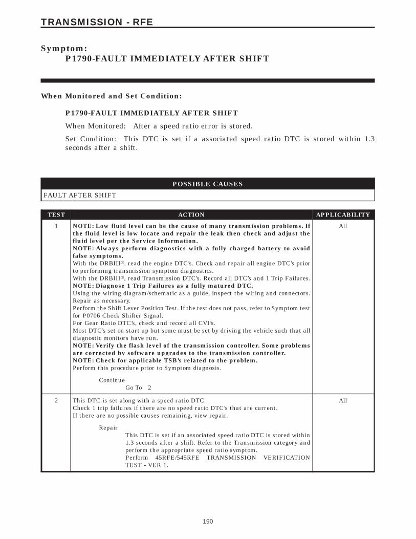
Symptom:P1790-FAULT IMMEDIATELY AFTER SHIFT
When Monitored and Set Condition:
P1790-FAULT IMMEDIATELY AFTER SHIFT
When Monitored: After a speed ratio error is stored.
Set Condition: This DTC is set if a associated speed ratio DTC is stored within 1.3seconds after a shift.
POSSIBLE CAUSES
FAULT AFTER SHIFT
TEST ACTION APPLICABILITY
1 NOTE: Low fluid level can be the cause of many transmission problems. Ifthe fluid level is low locate and repair the leak then check and adjust thefluid level per the Service Information.NOTE: Always perform diagnostics with a fully charged battery to avoidfalse symptoms.With the DRBIIIt, read the engine DTC’s. Check and repair all engine DTC’s priorto performing transmission symptom diagnostics.With the DRBIIIt, read Transmission DTC’s. Record all DTC’s and 1 Trip Failures.NOTE: Diagnose 1 Trip Failures as a fully matured DTC.Using the wiring diagram/schematic as a guide, inspect the wiring and connectors.Repair as necessary.Perform the Shift Lever Position Test. If the test does not pass, refer to Symptom testfor P0706 Check Shifter Signal.For Gear Ratio DTC’s, check and record all CVI’s.Most DTC’s set on start up but some must be set by driving the vehicle such that alldiagnostic monitors have run.NOTE: Verify the flash level of the transmission controller. Some problemsare corrected by software upgrades to the transmission controller.NOTE: Check for applicable TSB’s related to the problem.Perform this procedure prior to Symptom diagnosis.
All
ContinueGo To 2
2 This DTC is set along with a speed ratio DTC.Check 1 trip failures if there are no speed ratio DTC’s that are current.If there are no possible causes remaining, view repair.
All
RepairThis DTC is set if an associated speed ratio DTC is stored within1.3 seconds after a shift. Refer to the Transmission category andperform the appropriate speed ratio symptom.Perform 45RFE/545RFE TRANSMISSION VERIFICATIONTEST - VER 1.
190
TRANSMISSION - RFE
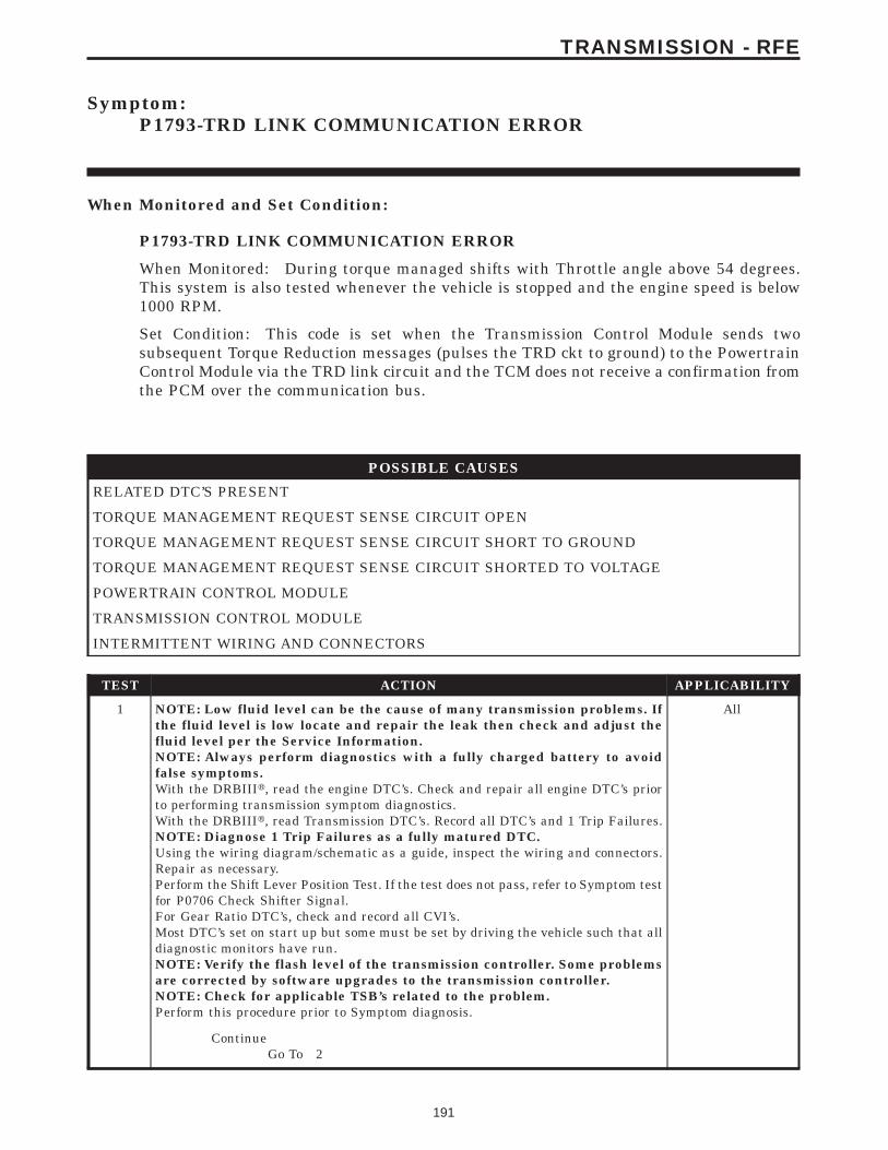
Symptom:P1793-TRD LINK COMMUNICATION ERROR
When Monitored and Set Condition:
P1793-TRD LINK COMMUNICATION ERROR
When Monitored: During torque managed shifts with Throttle angle above 54 degrees.This system is also tested whenever the vehicle is stopped and the engine speed is below1000 RPM.
Set Condition: This code is set when the Transmission Control Module sends twosubsequent Torque Reduction messages (pulses the TRD ckt to ground) to the PowertrainControl Module via the TRD link circuit and the TCM does not receive a confirmation fromthe PCM over the communication bus.
POSSIBLE CAUSES
RELATED DTC’S PRESENT
TORQUE MANAGEMENT REQUEST SENSE CIRCUIT OPEN
TORQUE MANAGEMENT REQUEST SENSE CIRCUIT SHORT TO GROUND
TORQUE MANAGEMENT REQUEST SENSE CIRCUIT SHORTED TO VOLTAGE
POWERTRAIN CONTROL MODULE
TRANSMISSION CONTROL MODULE
INTERMITTENT WIRING AND CONNECTORS
TEST ACTION APPLICABILITY
1 NOTE: Low fluid level can be the cause of many transmission problems. Ifthe fluid level is low locate and repair the leak then check and adjust thefluid level per the Service Information.NOTE: Always perform diagnostics with a fully charged battery to avoidfalse symptoms.With the DRBIIIt, read the engine DTC’s. Check and repair all engine DTC’s priorto performing transmission symptom diagnostics.With the DRBIIIt, read Transmission DTC’s. Record all DTC’s and 1 Trip Failures.NOTE: Diagnose 1 Trip Failures as a fully matured DTC.Using the wiring diagram/schematic as a guide, inspect the wiring and connectors.Repair as necessary.Perform the Shift Lever Position Test. If the test does not pass, refer to Symptom testfor P0706 Check Shifter Signal.For Gear Ratio DTC’s, check and record all CVI’s.Most DTC’s set on start up but some must be set by driving the vehicle such that alldiagnostic monitors have run.NOTE: Verify the flash level of the transmission controller. Some problemsare corrected by software upgrades to the transmission controller.NOTE: Check for applicable TSB’s related to the problem.Perform this procedure prior to Symptom diagnosis.
All
ContinueGo To 2
191
TRANSMISSION - RFE

TEST ACTION APPLICABILITY
2 With the DRBIIIt, check for other transmission DTC’sAre any of the DTCs P1694, P0731, P0732, P0733, P0734, and/or P1736 present also?
All
Yes → If any of these DTCs are present, disregard the P1793 DTC. Referto the Transmission category and perform the appropriate symp-tom..Perform 45RFE/545RFE TRANSMISSION VERIFICATIONTEST - VER 1.
No → Go To 3
3 With the DRBIIIt, Check the STARTS SINCE SET counter for P1793.NOTE: This counter only applies to the last DTC set.Is the STARTS SINCE SET set at 0?
All
Yes → Go To 4
No → Go To 9
4 Turn the ignition off to the lock position.Disconnect the TCM harness connector.Disconnect the PCM harness connector.Note: Check connectors - Clean/repair as necessary.Measure the resistance of the Torque Management Request Sense circuit from theTCM harness connector to the PCM harness connector.Is the resistance above 5.0 ohms?
All
Yes → Repair the Torque Management Request Sense circuit for anopen.Perform 45RFE/545RFE TRANSMISSION VERIFICATIONTEST - VER 1.
No → Go To 5
5 Turn the ignition off to the lock position.Disconnect the TCM harness connector.Disconnect the PCM harness connector.Note: Check connectors - Clean/repair as necessary.Measure the resistance between ground and the Torque Management Request Sensecircuit.Is the resistance below 5.0 ohms?
All
Yes → Repair the Torque Management Request Sense circuit for a shortto ground.Perform 45RFE/545RFE TRANSMISSION VERIFICATIONTEST - VER 1.
No → Go To 6
192
TRANSMISSION - RFE
P1793-TRD LINK COMMUNICATION ERROR — Continued

TEST ACTION APPLICABILITY
6 Turn the ignition off to the lock position.Disconnect the TCM harness connector.Note: Check connectors - Clean/repair as necessary.Ignition on, engine not running.Measure the voltage of the Torque Management Request Sense circuit in the TCMharness connector.Is the voltage above 10.5 volts?
All
Yes → Repair the Torque Management Request Sense circuit for a shortto voltage.Perform 45RFE/545RFE TRANSMISSION VERIFICATIONTEST - VER 1.
No → Go To 7
7 Turn the ignition switch to the lock position.Disconnect the TCM harness connector.Note: Check connectors - Clean/repair as necessary.Turn the ignition on.Measure the voltage of the Torque Management Request Sense circuit in the TCMharness connector.Is the voltage above 7.0 volts?
All
Yes → Replace the Transmission Control Module per the Service Infor-mation. WITH THE DRBIIIt PERFORM QUICK LEARNPerform 45RFE/545RFE TRANSMISSION VERIFICATIONTEST - VER 1.
No → Go To 8
8 Using the schematics as a guide, inspect the wiring and connectors. Repair asnecessary. Pay particular attention to all power and ground circuits.If there are no possible causes remaining, view repair.
All
RepairReplace and program the Powertrain Control Module per theService Information. After completion of the Powertrain Verifica-tion test make sure to perform Transmission Verification Test 1.Perform POWERTRAIN VERIFICATION TEST VER - 2.
9 The conditions necessary to set this DTC are not present at this time.Using the schematics as a guide, inspect the wiring and connectors specific to thiscircuit.Wiggle the wires while checking for shorts and open circuits.With the DRBIIIt, check the EATX DTC EVENT DATA to help identify theconditions in which the DTC was set.Were there any problems found?
All
Yes → Repair as necessary.Perform 45RFE/545RFE TRANSMISSION VERIFICATIONTEST - VER 1.
No → Test Complete.
193
TRANSMISSION - RFE
P1793-TRD LINK COMMUNICATION ERROR — Continued

Symptom:P1794-SPEED SENSOR GROUND ERROR
When Monitored and Set Condition:
P1794-SPEED SENSOR GROUND ERROR
When Monitored: The gear ratio is monitored continuously while the Transmission is ingear.
Set Condition: After a TCM reset in neutral and a ratio of input to output, of 1 to 2. ThisDTC can take up to five minutes of problem identification before illuminating the MIL.
POSSIBLE CAUSES
SPEED SENSOR GROUND CIRCUIT OPEN
SPEED SENSOR GROUND CIRCUIT SHORT TO GROUND
SPEED SENSOR GROUND CIRCUIT SHORT TO VOLTAGE
TRANSMISSION CONTROL MODULE
INTERMITTENT WIRING AND CONNECTORS
TEST ACTION APPLICABILITY
1 NOTE: Low fluid level can be the cause of many transmission problems. Ifthe fluid level is low locate and repair the leak then check and adjust thefluid level per the Service Information.NOTE: Always perform diagnostics with a fully charged battery to avoidfalse symptoms.With the DRBIIIt, read the engine DTC’s. Check and repair all engine DTC’s priorto performing transmission symptom diagnostics.With the DRBIIIt, read Transmission DTC’s. Record all DTC’s and 1 Trip Failures.NOTE: Diagnose 1 Trip Failures as a fully matured DTC.Using the wiring diagram/schematic as a guide, inspect the wiring and connectors.Repair as necessary.Perform the Shift Lever Position Test. If the test does not pass, refer to Symptom testfor P0706 Check Shifter Signal.For Gear Ratio DTC’s, check and record all CVI’s.Most DTC’s set on start up but some must be set by driving the vehicle such that alldiagnostic monitors have run.NOTE: Verify the flash level of the transmission controller. Some problemsare corrected by software upgrades to the transmission controller.NOTE: Check for applicable TSB’s related to the problem.Perform this procedure prior to Symptom diagnosis.
All
ContinueGo To 2
2 Engine Running. Shift lever in park.With the DRBIIIt, read the Transmission Input and Output Speed Sensor RPM.Is the Output Speed Sensor reading twice the Input Speed Sensor reading?
All
Yes → Go To 3
No → Go To 8
194
TRANSMISSION - RFE

TEST ACTION APPLICABILITY
3 Turn the ignition off to the lock position.Remove the Starter Relay.NOTE: Failure to remove the Starter Relay can cause a Transmission - NoResponse condition.Install Transmission Simulator, Miller tool #8333.Note: Check connectors - Clean/repair as necessary.Ignition on, engine not running.With the Transmission Simulator, set the Input/Output Speed selector switch to the3000/1000 position. Turn the Input/Output Speed switch to ON.With the DRBIIIt, monitor the Input and Output Speed Sensor RPM.Does the Input Speed read 3000 RPM and the Output Speed read 1000 RPM, ± 50RPM?
All
Yes → Go To 8
No → Go To 4
4 Turn the ignition off to the lock position.Disconnect the TCM harness connector.Disconnect the Input and Output Speed Sensor harness connector.Disconnect the Transmission Solenoid/TRS Assembly harness connector.Note: Check connectors - Clean/repair as necessary.Measure the resistance of the Speed Sensor Ground circuit from the TCM harnessconnector to the Transmission Solenoid/TRS Assembly, Input and Output SpeedSensor harness connectors.Is the resistance above 5.0 ohms on any of the above measurements?
All
Yes → Repair the Speed Sensor Ground circuit for an open.Perform 45RFE/545RFE TRANSMISSION VERIFICATIONTEST - VER 1.
No → Go To 5
5 Turn the ignition off to the lock position.Disconnect the TCM harness connector.Disconnect the Transmission Solenoid/TRS Assembly harness connector.Disconnect the Input and Output Speed Sensor harness connectors.Note: Check connectors - Clean/repair as necessary.Measure the resistance between the Input Sensor Ground circuit and ground.Is the resistance below 5.0 ohms?
All
Yes → Repair the Speed Senor Ground circuit for a short to ground.Perform 45RFE/545RFE TRANSMISSION VERIFICATIONTEST - VER 1.
No → Go To 6
6 Turn the ignition off to the lock position.Disconnect the Input and Output Speed Sensor harness connectors.Note: Check connectors - Clean/repair as necessary.Ignition on, engine not running.Measure the voltage of the Speed Sensor Ground circuit.Is the voltage above 0.5 volt?
All
Yes → Repair the Speed Sensor Ground circuit for a short to voltage.Perform 45RFE/545RFE TRANSMISSION VERIFICATIONTEST - VER 1.
No → Go To 7
195
TRANSMISSION - RFE
P1794-SPEED SENSOR GROUND ERROR — Continued

TEST ACTION APPLICABILITY
7 Using the schematics as a guide, inspect the wiring and connectors. Repair asnecessary. Pay particular attention to all power and ground circuits.If there are no possible causes remaining, view repair.
All
RepairReplace the Transmission Control Module per the Service Infor-mation. WITH THE DRBIIIt PERFORM QUICK LEARNPerform 45RFE/545RFE TRANSMISSION VERIFICATIONTEST - VER 1.
8 The conditions necessary to set this DTC are not present at this time.Using the schematics as a guide, inspect the wiring and connectors specific to thiscircuit.Wiggle the wires while checking for shorts and open circuits.With the DRBIIIt, check the EATX DTC EVENT DATA to help identify theconditions in which the DTC was set.Were there any problems found?
All
Yes → Repair as necessary.Perform 45RFE/545RFE TRANSMISSION VERIFICATIONTEST - VER 1.
No → Test Complete.
196
TRANSMISSION - RFE
P1794-SPEED SENSOR GROUND ERROR — Continued
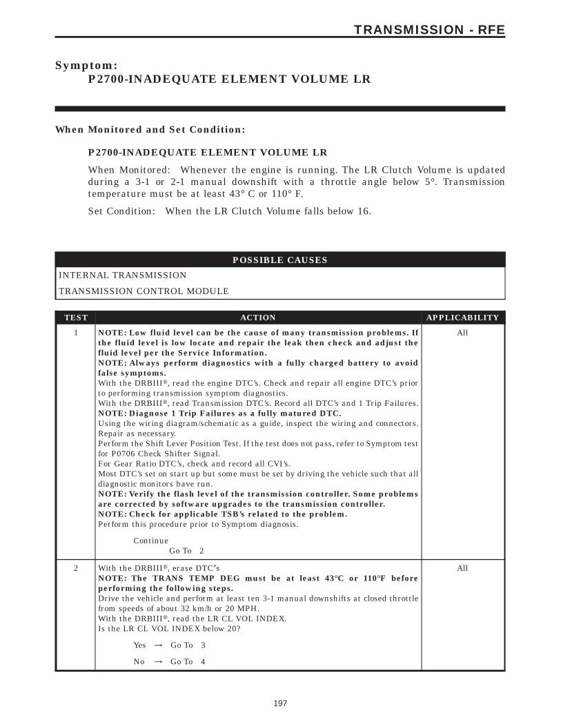
Symptom:P2700-INADEQUATE ELEMENT VOLUME LR
When Monitored and Set Condition:
P2700-INADEQUATE ELEMENT VOLUME LR
When Monitored: Whenever the engine is running. The LR Clutch Volume is updatedduring a 3-1 or 2-1 manual downshift with a throttle angle below 5°. Transmissiontemperature must be at least 43° C or 110° F.
Set Condition: When the LR Clutch Volume falls below 16.
POSSIBLE CAUSES
INTERNAL TRANSMISSION
TRANSMISSION CONTROL MODULE
TEST ACTION APPLICABILITY
1 NOTE: Low fluid level can be the cause of many transmission problems. Ifthe fluid level is low locate and repair the leak then check and adjust thefluid level per the Service Information.NOTE: Always perform diagnostics with a fully charged battery to avoidfalse symptoms.With the DRBIIIt, read the engine DTC’s. Check and repair all engine DTC’s priorto performing transmission symptom diagnostics.With the DRBIIIt, read Transmission DTC’s. Record all DTC’s and 1 Trip Failures.NOTE: Diagnose 1 Trip Failures as a fully matured DTC.Using the wiring diagram/schematic as a guide, inspect the wiring and connectors.Repair as necessary.Perform the Shift Lever Position Test. If the test does not pass, refer to Symptom testfor P0706 Check Shifter Signal.For Gear Ratio DTC’s, check and record all CVI’s.Most DTC’s set on start up but some must be set by driving the vehicle such that alldiagnostic monitors have run.NOTE: Verify the flash level of the transmission controller. Some problemsare corrected by software upgrades to the transmission controller.NOTE: Check for applicable TSB’s related to the problem.Perform this procedure prior to Symptom diagnosis.
All
ContinueGo To 2
2 With the DRBIIIt, erase DTC9sNOTE: The TRANS TEMP DEG must be at least 43°C or 110°F beforeperforming the following steps.Drive the vehicle and perform at least ten 3-1 manual downshifts at closed throttlefrom speeds of about 32 km/h or 20 MPH.With the DRBIIIt, read the LR CL VOL INDEX.Is the LR CL VOL INDEX below 20?
All
Yes → Go To 3
No → Go To 4
197
TRANSMISSION - RFE

TEST ACTION APPLICABILITY
3 If there are no possible causes remaining, view repair. All
RepairRepair internal transmission as necessary. Refer to the ServiceInformation for the proper repair procedure for components re-lated to the LR clutch. A broken or weak return spring or adislocated snap ring could cause this problem.Perform 45RFE/545RFE TRANSMISSION VERIFICATIONTEST - VER 1.
4 NOTE: The TRANS TEMP DEG must be at least 43° C or 110° F beforeperforming the following steps.Perform eight learnable starts. A learnable start is defined as follows: Start engine.From a standstill, accelerate lightly to 80 km/h or 50 MPH, then brake lightly to astop. Turn off engine.With the DRBIIIt, record the CL VOL INDEX (CVI) for all clutches.With the DRBIIIt, perform a BATTERY DISCONNECT.With the DRBIIIt, read the CVI’s and compare them to the readings recorded beforethe BATTERY DISCONNECT.Are any of the CVI’s less than 5 or different than before the BATTERY DISCON-NECT?
All
Yes → Go To 5
No → Test Complete.
5 Using the schematics as a guide, inspect the wiring and connectors. Repair asnecessary. Pay particular attention to all power and ground circuits.If there are no possible causes remaining, view repair.
All
RepairReplace the Transmission Control Module per the Service Infor-mation. WITH THE DRBIIIt PERFORM QUICK LEARNPerform 45RFE/545RFE TRANSMISSION VERIFICATIONTEST - VER 1.
198
TRANSMISSION - RFE
P2700-INADEQUATE ELEMENT VOLUME LR — Continued
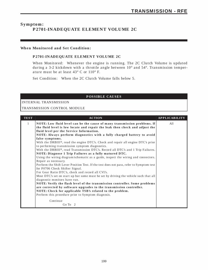
Symptom:P2701-INADEQUATE ELEMENT VOLUME 2C
When Monitored and Set Condition:
P2701-INADEQUATE ELEMENT VOLUME 2C
When Monitored: Whenever the engine is running. The 2C Clutch Volume is updatedduring a 3-2 kickdown with a throttle angle between 10° and 54°. Transmission temper-ature must be at least 43° C or 110° F.
Set Condition: When the 2C Clutch Volume falls below 5.
POSSIBLE CAUSES
INTERNAL TRANSMISSION
TRANSMISSION CONTROL MODULE
TEST ACTION APPLICABILITY
1 NOTE: Low fluid level can be the cause of many transmission problems. Ifthe fluid level is low locate and repair the leak then check and adjust thefluid level per the Service Information.NOTE: Always perform diagnostics with a fully charged battery to avoidfalse symptoms.With the DRBIIIt, read the engine DTC’s. Check and repair all engine DTC’s priorto performing transmission symptom diagnostics.With the DRBIIIt, read Transmission DTC’s. Record all DTC’s and 1 Trip Failures.NOTE: Diagnose 1 Trip Failures as a fully matured DTC.Using the wiring diagram/schematic as a guide, inspect the wiring and connectors.Repair as necessary.Perform the Shift Lever Position Test. If the test does not pass, refer to Symptom testfor P0706 Check Shifter Signal.For Gear Ratio DTC’s, check and record all CVI’s.Most DTC’s set on start up but some must be set by driving the vehicle such that alldiagnostic monitors have run.NOTE: Verify the flash level of the transmission controller. Some problemsare corrected by software upgrades to the transmission controller.NOTE: Check for applicable TSB’s related to the problem.Perform this procedure prior to Symptom diagnosis.
All
ContinueGo To 2
199
TRANSMISSION - RFE

TEST ACTION APPLICABILITY
2 With the DRBIIIt, erase DTC9sDrive the vehicle at about 80 km/h or 50 MPH, then depress the OD off button. Thiswill put the vehicle into third gear.NOTE: The TRANS TEMP DEG must be at least 43° C or 110° F beforeperforming the following steps.Perform at least ten 3-2 kickdowns by depressing the throttle between 10 and 54 TPSDEGREES at speeds of about 80 km/h or 50 MPH.With the DRBIIIt, read the 2C CL VOL INDEX.Is the 2C CL VOL INDEX below 10?
All
Yes → Go To 3
No → Go To 4
3 If there are no possible causes remaining, view repair. All
RepairRepair internal transmission as necessary. Refer to the ServiceInformation for the proper repair procedure for components re-lated to the 2C clutch. A broken or weak return spring or adislocated snap ring could cause this problem.Perform 45RFE/545RFE TRANSMISSION VERIFICATIONTEST - VER 1.
4 NOTE: The TRANS TEMP DEG must be at least 43° C or 110° F beforeperforming the following steps.Perform eight learnable starts. A learnable start is defined as follows: Start engine.From a standstill, accelerate lightly to 80 km/h or 50 MPH, then brake lightly to astop. Turn off engine.With the DRBIIIt, record the CL VOL INDEX (CVI) for all clutchesWith the DRBIIIt, perform a BATTERY DISCONNECT.With the DRBIIIt, read the CVI’s and compare them to the readings recorded beforethe BATTERY DISCONNECT.Are any of the CVI’s less than 5 or different than before the BATTERY DISCON-NECT?
All
Yes → Go To 5
No → Test Complete.
5 Using the schematics as a guide, inspect the wiring and connectors. Repair asnecessary. Pay particular attention to all power and ground circuits.If there are no possible causes remaining, view repair.
All
RepairReplace the Transmission Control Module per the Service Infor-mation. WITH THE DRBIIIt PERFORM QUICK LEARNPerform 45RFE/545RFE TRANSMISSION VERIFICATIONTEST - VER 1.
200
TRANSMISSION - RFE
P2701-INADEQUATE ELEMENT VOLUME 2C — Continued
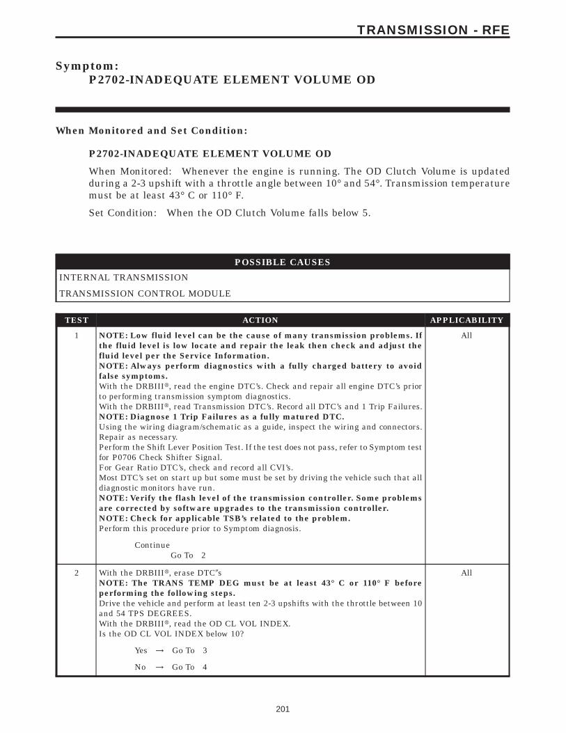
Symptom:P2702-INADEQUATE ELEMENT VOLUME OD
When Monitored and Set Condition:
P2702-INADEQUATE ELEMENT VOLUME OD
When Monitored: Whenever the engine is running. The OD Clutch Volume is updatedduring a 2-3 upshift with a throttle angle between 10° and 54°. Transmission temperaturemust be at least 43° C or 110° F.
Set Condition: When the OD Clutch Volume falls below 5.
POSSIBLE CAUSES
INTERNAL TRANSMISSION
TRANSMISSION CONTROL MODULE
TEST ACTION APPLICABILITY
1 NOTE: Low fluid level can be the cause of many transmission problems. Ifthe fluid level is low locate and repair the leak then check and adjust thefluid level per the Service Information.NOTE: Always perform diagnostics with a fully charged battery to avoidfalse symptoms.With the DRBIIIt, read the engine DTC’s. Check and repair all engine DTC’s priorto performing transmission symptom diagnostics.With the DRBIIIt, read Transmission DTC’s. Record all DTC’s and 1 Trip Failures.NOTE: Diagnose 1 Trip Failures as a fully matured DTC.Using the wiring diagram/schematic as a guide, inspect the wiring and connectors.Repair as necessary.Perform the Shift Lever Position Test. If the test does not pass, refer to Symptom testfor P0706 Check Shifter Signal.For Gear Ratio DTC’s, check and record all CVI’s.Most DTC’s set on start up but some must be set by driving the vehicle such that alldiagnostic monitors have run.NOTE: Verify the flash level of the transmission controller. Some problemsare corrected by software upgrades to the transmission controller.NOTE: Check for applicable TSB’s related to the problem.Perform this procedure prior to Symptom diagnosis.
All
ContinueGo To 2
2 With the DRBIIIt, erase DTC9sNOTE: The TRANS TEMP DEG must be at least 43° C or 110° F beforeperforming the following steps.Drive the vehicle and perform at least ten 2-3 upshifts with the throttle between 10and 54 TPS DEGREES.With the DRBIIIt, read the OD CL VOL INDEX.Is the OD CL VOL INDEX below 10?
All
Yes → Go To 3
No → Go To 4
201
TRANSMISSION - RFE

TEST ACTION APPLICABILITY
3 If there are no possible causes remaining, view repair. All
RepairRepair internal transmission as necessary. Refer to the ServiceInformation for the proper repair procedure for components re-lated to the OD clutch. A broken or weak return spring or adislocated snap ring could cause this problem.Perform 45RFE/545RFE TRANSMISSION VERIFICATIONTEST - VER 1.
4 NOTE: The TRANS TEMP DEG must be at least 43° C or 110° F beforeperforming the following steps.Perform eight learnable starts. A learnable start is defined as follows: Start engine.From a standstill, accelerate lightly to 80 km/h or 50 MPH, then brake lightly to astop. Turn off engine.With the DRBIIIt, record the CL VOL INDEX (CVI) for all clutches.With the DRBIIIt, perform a BATTERY DISCONNECT.With the DRBIIIt, read the CVI’s and compare them to the readings recorded beforethe BATTERY DISCONNECT.Are any of the CVI’s less than 5 or different than before the BATTERY DISCON-NECT?
All
Yes → Go To 5
No → Test Complete.
5 Using the schematics as a guide, inspect the wiring and connectors. Repair asnecessary. Pay particular attention to all power and ground circuits.If there are no possible causes remaining, view repair.
All
RepairReplace the Transmission Control Module per the Service Infor-mation. WITH THE DRBIIIt PERFORM QUICK LEARNPerform 45RFE/545RFE TRANSMISSION VERIFICATIONTEST - VER 1.
202
TRANSMISSION - RFE
P2702-INADEQUATE ELEMENT VOLUME OD — Continued
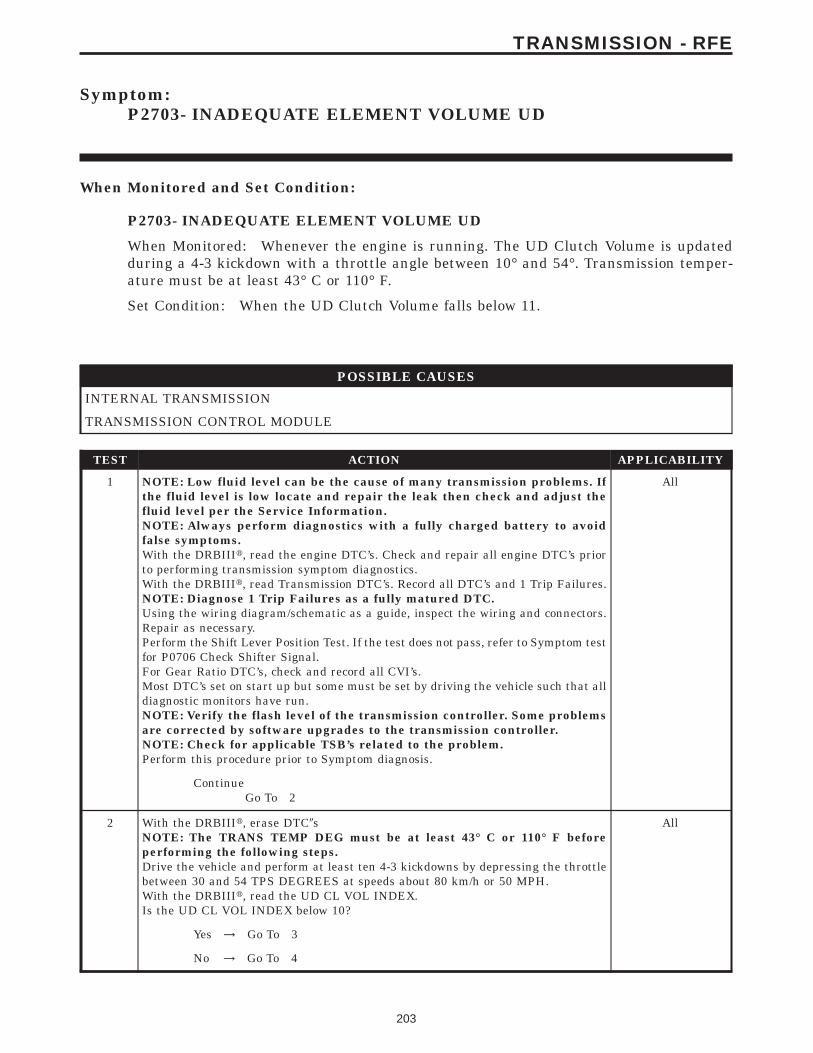
Symptom:P2703- INADEQUATE ELEMENT VOLUME UD
When Monitored and Set Condition:
P2703- INADEQUATE ELEMENT VOLUME UD
When Monitored: Whenever the engine is running. The UD Clutch Volume is updatedduring a 4-3 kickdown with a throttle angle between 10° and 54°. Transmission temper-ature must be at least 43° C or 110° F.
Set Condition: When the UD Clutch Volume falls below 11.
POSSIBLE CAUSES
INTERNAL TRANSMISSION
TRANSMISSION CONTROL MODULE
TEST ACTION APPLICABILITY
1 NOTE: Low fluid level can be the cause of many transmission problems. Ifthe fluid level is low locate and repair the leak then check and adjust thefluid level per the Service Information.NOTE: Always perform diagnostics with a fully charged battery to avoidfalse symptoms.With the DRBIIIt, read the engine DTC’s. Check and repair all engine DTC’s priorto performing transmission symptom diagnostics.With the DRBIIIt, read Transmission DTC’s. Record all DTC’s and 1 Trip Failures.NOTE: Diagnose 1 Trip Failures as a fully matured DTC.Using the wiring diagram/schematic as a guide, inspect the wiring and connectors.Repair as necessary.Perform the Shift Lever Position Test. If the test does not pass, refer to Symptom testfor P0706 Check Shifter Signal.For Gear Ratio DTC’s, check and record all CVI’s.Most DTC’s set on start up but some must be set by driving the vehicle such that alldiagnostic monitors have run.NOTE: Verify the flash level of the transmission controller. Some problemsare corrected by software upgrades to the transmission controller.NOTE: Check for applicable TSB’s related to the problem.Perform this procedure prior to Symptom diagnosis.
All
ContinueGo To 2
2 With the DRBIIIt, erase DTC9sNOTE: The TRANS TEMP DEG must be at least 43° C or 110° F beforeperforming the following steps.Drive the vehicle and perform at least ten 4-3 kickdowns by depressing the throttlebetween 30 and 54 TPS DEGREES at speeds about 80 km/h or 50 MPH.With the DRBIIIt, read the UD CL VOL INDEX.Is the UD CL VOL INDEX below 10?
All
Yes → Go To 3
No → Go To 4
203
TRANSMISSION - RFE

TEST ACTION APPLICABILITY
3 If there are no possible causes remaining, view repair. All
RepairRepair internal transmission as necessary. Refer to the ServiceInformation for the proper repair procedure for components re-lated to the UD clutch. A broken or weak return spring or adislocated snap ring could cause this problem.Perform 45RFE/545RFE TRANSMISSION VERIFICATIONTEST - VER 1.
4 NOTE: The TRANS TEMP DEG must be at least 43° C or 110° F beforeperforming the following steps.Perform eight learnable starts. A learnable start is defined as follows: Start engine.From a standstill, accelerate lightly to 80 km/h or 50 MPH, then brake lightly to astop. Turn off engine.With the DRBIIIt, record CL VOL INDEX (CVI) for all clutches.With the DRBIIIt, perform a BATTERY DISCONNECT.With the DRBIIIt, read the CVI’s and compare them to the readings recorded beforethe BATTERY DISCONNECT.Are any of the CVI’s less than 5 or different than before the BATTERY DISCON-NECT?
All
Yes → Go To 5
No → Test Complete.
5 Using the schematics as a guide, inspect the wiring and connectors. Repair asnecessary. Pay particular attention to all power and ground circuits.If there are no possible causes remaining, view repair.
All
RepairReplace the Transmission Control Module per the Service Infor-mation. WITH THE DRBIIIt PERFORM QUICK LEARNPerform 45RFE/545RFE TRANSMISSION VERIFICATIONTEST - VER 1.
204
TRANSMISSION - RFE
P2703- INADEQUATE ELEMENT VOLUME UD — Continued
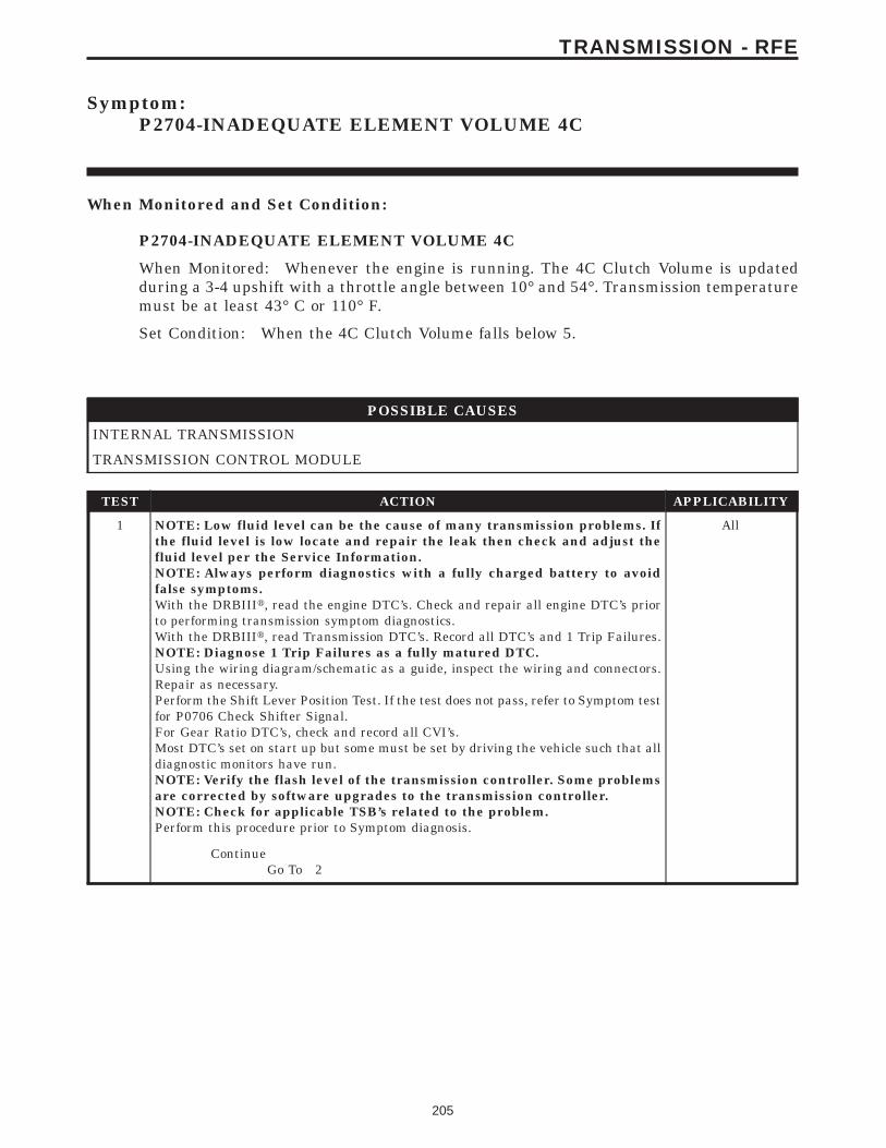
Symptom:P2704-INADEQUATE ELEMENT VOLUME 4C
When Monitored and Set Condition:
P2704-INADEQUATE ELEMENT VOLUME 4C
When Monitored: Whenever the engine is running. The 4C Clutch Volume is updatedduring a 3-4 upshift with a throttle angle between 10° and 54°. Transmission temperaturemust be at least 43° C or 110° F.
Set Condition: When the 4C Clutch Volume falls below 5.
POSSIBLE CAUSES
INTERNAL TRANSMISSION
TRANSMISSION CONTROL MODULE
TEST ACTION APPLICABILITY
1 NOTE: Low fluid level can be the cause of many transmission problems. Ifthe fluid level is low locate and repair the leak then check and adjust thefluid level per the Service Information.NOTE: Always perform diagnostics with a fully charged battery to avoidfalse symptoms.With the DRBIIIt, read the engine DTC’s. Check and repair all engine DTC’s priorto performing transmission symptom diagnostics.With the DRBIIIt, read Transmission DTC’s. Record all DTC’s and 1 Trip Failures.NOTE: Diagnose 1 Trip Failures as a fully matured DTC.Using the wiring diagram/schematic as a guide, inspect the wiring and connectors.Repair as necessary.Perform the Shift Lever Position Test. If the test does not pass, refer to Symptom testfor P0706 Check Shifter Signal.For Gear Ratio DTC’s, check and record all CVI’s.Most DTC’s set on start up but some must be set by driving the vehicle such that alldiagnostic monitors have run.NOTE: Verify the flash level of the transmission controller. Some problemsare corrected by software upgrades to the transmission controller.NOTE: Check for applicable TSB’s related to the problem.Perform this procedure prior to Symptom diagnosis.
All
ContinueGo To 2
205
TRANSMISSION - RFE

TEST ACTION APPLICABILITY
2 NOTE: Check the Transmission Fluid Level. If the Transmission Fluid is low,repair any Transmission Fluid leak as necessary and adjust the Transmis-sion Fluid Level per the Service Information.With the DRBIIIt, record the 4C CL VOL INDEX.With the DRBIIIt, erase DTC’s.Perform at least 10 3-4 upshifts with the throttle between 10 and 54 degrees. TheTransmission Temperature must be at least 43°C or 110 °F.With the DRBIIIt, read the 4C CL VOL INDEX.Is the current 4C CL VOL INDEX below 10?
All
Yes → Go To 3
No → Go To 4
3 If there are no possible causes remaining, view repair. All
RepairRepair the transmission as necessary. Refer to the Service Infor-mation for proper repair procedures for components related to the4th clutch. A broken or weak return spring or a dislocated snapring could cause this problem.Perform 45RFE/545RFE TRANSMISSION VERIFICATIONTEST - VER 1.
4 Perform eight learnable starts. A learnable start is defined as follows: Start engine.From a standstill, accelerate lightly to 50 MPH, then brake lightly to a stop. Turn offengine.With the DRBIIIt, record the CL VOL INDEX (CVI) for all clutches.With the DRBIIIt, perform a BATTERY DISCONNECT.With the DRBIIIt, read the CVI’s and compare them to the reading recorded beforethe BATTERY DISCONNECT.Are any of the CVI’s less than 5 or different than before the BATTERY DISCON-NECT?
All
Yes → Go To 5
No → Test Complete.
5 Using the schematics as a guide, inspect the wiring and connectors. Repair asnecessary. Pay particular attention to all power and ground circuits.If there are no possible causes remaining, view repair.
All
RepairReplace the Transmission Control Module per the Service Infor-mation. WITH THE DRBIIIt PERFORM QUICK LEARNPerform 45RFE/545RFE TRANSMISSION VERIFICATIONTEST - VER 1.
206
TRANSMISSION - RFE
P2704-INADEQUATE ELEMENT VOLUME 4C — Continued

Symptom:P2706-MS SOLENOID CIRCUIT
When Monitored and Set Condition:
P2706-MS SOLENOID CIRCUIT
When Monitored: Initially at power-up, then every 10 seconds thereafter. It will also betested immediately after a gear ratio or pressure switch error is detected.
Set Condition: After three consecutive solenoid continuity tests failures. After one failureif a test is run in response to a gear ratio or pressure switch error.
POSSIBLE CAUSES
RELATED RELAY DTC’S PRESENT
MS SOLENOID CONTROL CIRCUIT OPEN
TRANSMISSION CONTROL RELAY OUTPUT CIRCUIT OPEN
MS SOLENOID CONTROL CIRCUIT SHORT TO GROUND
MS SOLENOID CIRCUIT SHORT TO VOLTAGE
MS SOLENOID
TRANSMISSION CONTROL MODULE
INTERMITTENT WIRING AND CONNECTORS
TEST ACTION APPLICABILITY
1 NOTE: Low fluid level can be the cause of many transmission problems. Ifthe fluid level is low locate and repair the leak then check and adjust thefluid level per the Service Information.NOTE: Always perform diagnostics with a fully charged battery to avoidfalse symptoms.With the DRBIIIt, read the engine DTC’s. Check and repair all engine DTC’s priorto performing transmission symptom diagnostics.With the DRBIIIt, read Transmission DTC’s. Record all DTC’s and 1 Trip Failures.NOTE: Diagnose 1 Trip Failures as a fully matured DTC.Using the wiring diagram/schematic as a guide, inspect the wiring and connectors.Repair as necessary.Perform the Shift Lever Position Test. If the test does not pass, refer to Symptom testfor P0706 Check Shifter Signal.For Gear Ratio DTC’s, check and record all CVI’s.Most DTC’s set on start up but some must be set by driving the vehicle such that alldiagnostic monitors have run.NOTE: Verify the flash level of the transmission controller. Some problemsare corrected by software upgrades to the transmission controller.NOTE: Check for applicable TSB’s related to the problem.Perform this procedure prior to Symptom diagnosis.
All
ContinueGo To 2
207
TRANSMISSION - RFE

TEST ACTION APPLICABILITY
2 With the DRBIIIt, check for other transmission DTC’s.Are there any Transmission Control Relay related DTCs P0890, P0891, and/or P0888present?
All
Yes → Refer to the Transmission category and perform the appropriatesymptom.Perform 45RFE/545RFE TRANSMISSION VERIFICATIONTEST - VER 1.
No → Go To 3
3 With the DRBIIIt, Check the STARTS SINCE SET counter for P2706.NOTE: This counter only applies to the last DTC set.Is the STARTS SINCE SET counter set at 0?
All
Yes → Go To 4
No → Go To 11
4 Turn the ignition off to the lock position.Remove the Starter Relay from the PDC.NOTE: Failure to remove the Starter Relay can cause a Transmission - NoResponse condition.Install the Transmission Simulator, Miller tool #8333.Note: Check connectors - Clean/repair as necessary.Ignition on, engine not running..With the DRBIIIt, actuate the MS Solenoid.Monitor the MS Solenoid LED on the Transmission Simulator.Did the LED on the Transmission Simulator blink on and off?
All
Yes → Go To 5
No → Go To 6
5 If there are no possible causes remaining, view repair. All
RepairReplace Transmission Solenoid/TRS Assembly per the ServiceInformation.Perform 45RFE/545RFE TRANSMISSION VERIFICATIONTEST - VER 1.
6 Turn the ignition off to the lock position.Disconnect the TCM harness connector.Disconnect the Transmission Solenoid /TRS Assembly harness connectorNote: Check connectors - Clean/repair as necessary.Measure the resistance of the MS Solenoid Control circuit between the TCM harnessconnector to the Transmission Solenoid/TRS Assembly harness connector.Is the resistance above 5.0 ohms?
All
Yes → Repair the MS Solenoid Control circuit for an open.Perform 45RFE/545RFE TRANSMISSION VERIFICATIONTEST - VER 1.
No → Go To 7
208
TRANSMISSION - RFE
P2706-MS SOLENOID CIRCUIT — Continued

TEST ACTION APPLICABILITY
7 Turn the ignition off to the lock position.Disconnect the TCM harness connector.Disconnect the Transmission Solenoid/TRS Assembly harness connector.Note: Check connectors - Clean/repair as necessary.Measure the resistance between ground and the MS Solenoid Control circuit.Is the resistance below 5.0 ohms?
All
Yes → Repair the MS Solenoid Control circuit for a short to ground.Perform 45RFE/545RFE TRANSMISSION VERIFICATIONTEST - VER 1.
No → Go To 8
8 Turn the ignition off to the lock position.Disconnect the TCM harness connector.Disconnect the Transmission Solenoid/TRS Assembly harness connector.Remove the Transmission Control Relay from the PDC.Note: Check connectors - Clean/repair as necessary.Connect a jumper wire between the Fused B+ circuit and the Transmission ControlRelay Output circuit in the Transmission Control Relay connector.Ignition on, engine not running.Measure the voltage of the MS Solenoid Control circuit in the TCM harnessconnector.Is the voltage above 0.5 volt?
All
Yes → Repair the MS Solenoid Control circuit for a short to voltage.Perform 45RFE/545RFE TRANSMISSION VERIFICATIONTEST - VER 1.
No → Go To 9
9 Turn the ignition off to the lock position.Disconnect the Transmission Solenoid/TRS Assembly harness connector.Ignition on, engine not running.Using a 12-volt test light connected to ground, check the Transmission Control RelayOutput circuit in the Solenoid/TRS harness connector.NOTE: The test light must illuminate brightly. Compare the brightness tothat of a direct connection to the battery.Does the test light illuminate brightly?
All
Yes → Go To 10
No → Repair the Transmission Control Relay Output circuit for anopen. If the fuse is open make sure to check for a short to ground.Perform 45RFE/545RFE TRANSMISSION VERIFICATIONTEST - VER 1.
10 Using the schematics as a guide, inspect the wiring and connectors. Repair asnecessary. Pay particular attention to all power and ground circuits.If there are no possible causes remaining, view repair.
All
RepairReplace the Transmission Control Module per the Service Infor-mation. WITH THE DRBIIIt PERFORM QUICK LEARNPerform 45RFE/545RFE TRANSMISSION VERIFICATIONTEST - VER 1.
209
TRANSMISSION - RFE
P2706-MS SOLENOID CIRCUIT — Continued

TEST ACTION APPLICABILITY
11 The conditions necessary to set this DTC are not present at this time.Using the wiring diagram/schematic as a guide, inspect the wiring and connectors.Wiggle the wires while checking for shorts or open circuits.Check for any applicable TSB’s that may apply.With the DRBIIIt, check the EATX DTC EVENT DATA to help identify theconditions in which the DTC was set.Were there any problems found?
All
Yes → Repair as necessary.Perform 45RFE/545RFE TRANSMISSION VERIFICATIONTEST - VER 1.
No → Test Complete.
210
TRANSMISSION - RFE
P2706-MS SOLENOID CIRCUIT — Continued

Symptom:*BACKUP LAMPS COME ON WHILE SHIFTER IS NOT IN REVERSEPOSITION
POSSIBLE CAUSES
BACKUP SUPPLY CIRCUIT SHORT TO VOLTAGE
TRANSMISSION RANGE SENSOR
TEST ACTION APPLICABILITY
1 Ignition on, engine not running.Firmly apply brakes.Place the Shift Lever in the position which causes the Backup Lamps to come on atthe wrong time.Do the Backup Lamps come while the shifter is not in Reverse?
All
Yes → Go To 2
No → Test Complete.
2 Ignition on, engine not running.Place the shift lever in a position that causes the Backup Lamps to come on whenthey should not.Disconnect the Transmission Solenoid /TRS Assembly harness connector.NOTE: This will cause a DTC to be stored in the TCM. They must be erasedbefore returning the vehicle to the customer.Did the Backup Lamps go out when the connector was disconnected?
All
Yes → Go To 3
No → Go To 4
3 If there are no possible causes remaining, view repair. All
RepairReplace Transmission Solenoid/TRS Assembly per the ServiceInformation.Perform TRANSMISSION NO TROUBLE CODE VERIFICA-TION TEST.
4 Turn the ignition off to the lock position.Disconnect the Transmission Solenoid/TRS Assembly harness connector.Ignition on, engine not running.Measure the voltage of the Backup Light Supply circuit in the Solenoid/TRS harnessconnector.Is the voltage above 0.5 volt?
All
Yes → Repair the Backup Lights Supply circuit for a short to voltage.Perform TRANSMISSION NO TROUBLE CODE VERIFICA-TION TEST.
No → Test Complete.
211
TRANSMISSION - RFE
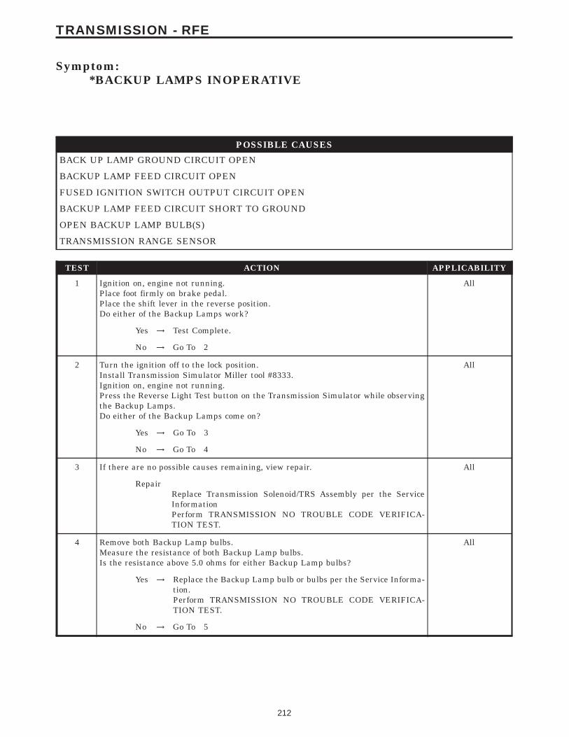
Symptom:*BACKUP LAMPS INOPERATIVE
POSSIBLE CAUSES
BACK UP LAMP GROUND CIRCUIT OPEN
BACKUP LAMP FEED CIRCUIT OPEN
FUSED IGNITION SWITCH OUTPUT CIRCUIT OPEN
BACKUP LAMP FEED CIRCUIT SHORT TO GROUND
OPEN BACKUP LAMP BULB(S)
TRANSMISSION RANGE SENSOR
TEST ACTION APPLICABILITY
1 Ignition on, engine not running.Place foot firmly on brake pedal.Place the shift lever in the reverse position.Do either of the Backup Lamps work?
All
Yes → Test Complete.
No → Go To 2
2 Turn the ignition off to the lock position.Install Transmission Simulator Miller tool #8333.Ignition on, engine not running.Press the Reverse Light Test button on the Transmission Simulator while observingthe Backup Lamps.Do either of the Backup Lamps come on?
All
Yes → Go To 3
No → Go To 4
3 If there are no possible causes remaining, view repair. All
RepairReplace Transmission Solenoid/TRS Assembly per the ServiceInformationPerform TRANSMISSION NO TROUBLE CODE VERIFICA-TION TEST.
4 Remove both Backup Lamp bulbs.Measure the resistance of both Backup Lamp bulbs.Is the resistance above 5.0 ohms for either Backup Lamp bulbs?
All
Yes → Replace the Backup Lamp bulb or bulbs per the Service Informa-tion.Perform TRANSMISSION NO TROUBLE CODE VERIFICA-TION TEST.
No → Go To 5
212
TRANSMISSION - RFE

TEST ACTION APPLICABILITY
5 Remove the Backup Lamp bulb.Using a 12-volt test light connected to 12-volts, check the Backup Lamp groundcircuit.Does the light illuminate brightly?
All
Yes → Go To 6
No → Repair the Back up Lamp ground circuit for an open.Perform TRANSMISSION NO TROUBLE CODE VERIFICA-TION TEST.
6 Turn the ignition off to the lock position.Remove the Backup Lamp bulb.Disconnect the Transmission Solenoid /TRS Assembly harness connector.Measure the resistance of the Backup Lamp Feed circuit from the Backup lampSocket to the Solenoid/TRS harness connector.Is the resistance above 5.0 ohms?
All
Yes → Repair the Backup Lamp Supply circuit for an open.Perform TRANSMISSION NO TROUBLE CODE VERIFICA-TION TEST.
No → Go To 7
7 Turn the ignition off to the lock position.Remove the Backup Lamp bulbs.Disconnect the Transmission Solenoid/TRS Assembly harness connector.Measure the resistance between the Backup Lamp Feed circuit and ground.Is the resistance below 5.0 ohms?
All
Yes → Repair the Backup Lamp Feed circuit for a short to ground. Checkthe Fused Ignition Switch Output (RUN) fuse and replace ifnecessary.Perform TRANSMISSION NO TROUBLE CODE VERIFICA-TION TEST.
No → Go To 8
8 Turn the ignition off to the lock position.Disconnect the Transmission Solenoid /TRS Assembly harness connector.Ignition on, engine not running.Using a 12-volt test light connected to ground, check the Fused Ignition SwitchOutput circuit.NOTE: The test light must illuminate brightly. Compare the brightness tothat of a direct connection to the battery.Does the test light illuminate brightly?
All
Yes → Test Complete.
No → Repair the Fused Ignition Switch Output circuit for an open. Ifthe fuse is open make sure to check or a short to ground.Perform TRANSMISSION NO TROUBLE CODE VERIFICA-TION TEST.
213
TRANSMISSION - RFE
*BACKUP LAMPS INOPERATIVE — Continued
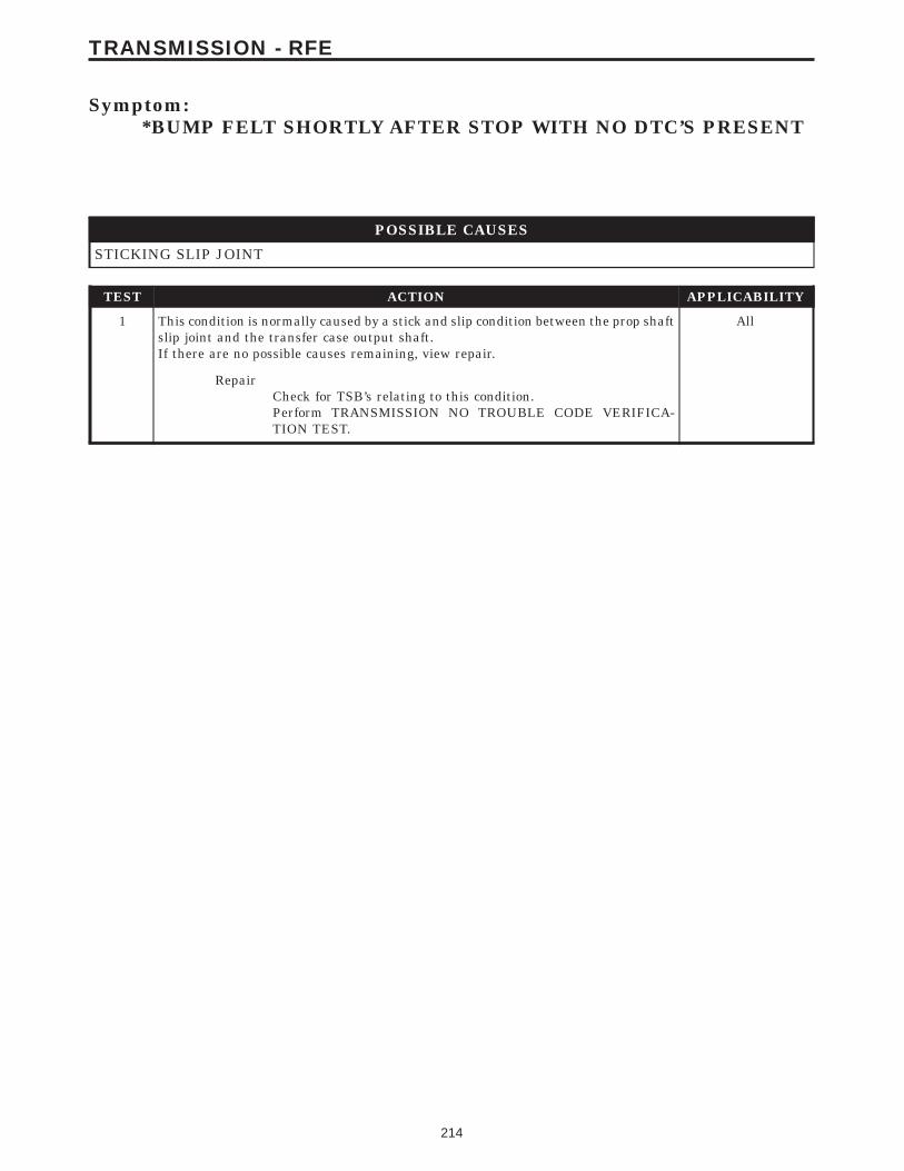
Symptom:*BUMP FELT SHORTLY AFTER STOP WITH NO DTC’S PRESENT
POSSIBLE CAUSES
STICKING SLIP JOINT
TEST ACTION APPLICABILITY
1 This condition is normally caused by a stick and slip condition between the prop shaftslip joint and the transfer case output shaft.If there are no possible causes remaining, view repair.
All
RepairCheck for TSB’s relating to this condition.Perform TRANSMISSION NO TROUBLE CODE VERIFICA-TION TEST.
214
TRANSMISSION - RFE
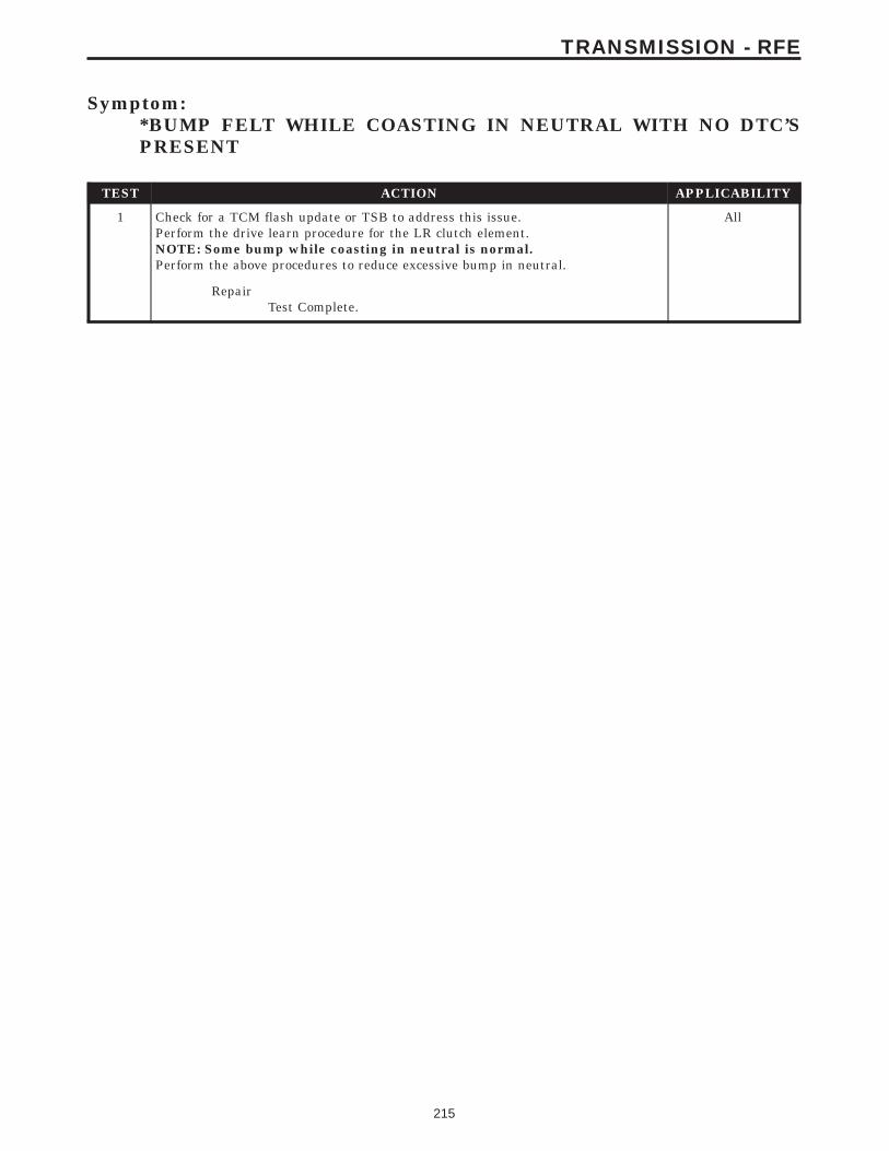
Symptom:*BUMP FELT WHILE COASTING IN NEUTRAL WITH NO DTC’SPRESENT
TEST ACTION APPLICABILITY
1 Check for a TCM flash update or TSB to address this issue.Perform the drive learn procedure for the LR clutch element.NOTE: Some bump while coasting in neutral is normal.Perform the above procedures to reduce excessive bump in neutral.
All
RepairTest Complete.
215
TRANSMISSION - RFE

Symptom:*CHECKING PARK/NEUTRAL SWITCH OPERATION
POSSIBLE CAUSES
PARK/NEUTRAL POSITION SWITCH SENSE CIRCUIT OPEN
PARK/NEUTRAL POSITION SWITCH SENSE CIRCUIT SHORT TO GROUND
POWERTRAIN CONTROL MODULE
INTERMITTENT WIRING AND CONNECTORS
TEST ACTION APPLICABILITY
1 Ignition on, engine not running.With the DRBIIIt, monitor the P/N Position Switch Input status.Move the gear selector through all gear positions, Park to 1st and back to Park.Did the DRB display P/N and D/R in the correct gear positions?
All
Yes → Go To 2
No → Go To 3
2 The condition is not present at this time.Using the schematics as a guide, inspect the wiring and connectors specific to thiscircuit.Wiggle the wires while checking for shorted and open circuits.Were there any problems found?
All
Yes → Repair as necessary.Perform TRANSMISSION NO TROUBLE CODE VERIFICA-TION TEST.
No → Test Complete.
3 Turn the ignition off to the lock position.Disconnect the PCM harness connector.Disconnect the PNP Switch harness connector.Check connectors - Clean/repair as necessaryMeasure the resistance of the PNP Switch Sense circuit between the PCM harnessconnector and the PNP Switch harness connector.Is the resistance below 5.0 ohms?
All
Yes → Go To 4
No → Repair the Park/Neutral Position Switch Sense circuit for anopen.Perform TRANSMISSION NO TROUBLE CODE VERIFICA-TION TEST.
216
TRANSMISSION - RFE
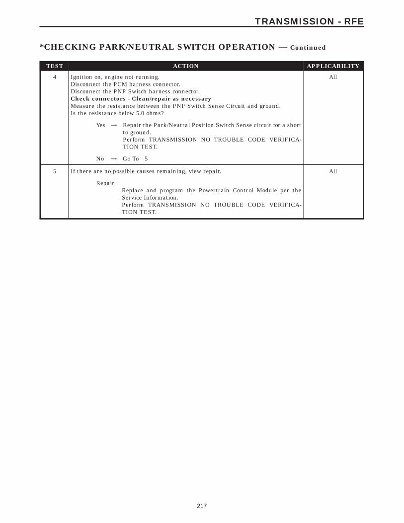
TEST ACTION APPLICABILITY
4 Ignition on, engine not running.Disconnect the PCM harness connector.Disconnect the PNP Switch harness connector.Check connectors - Clean/repair as necessaryMeasure the resistance between the PNP Switch Sense Circuit and ground.Is the resistance below 5.0 ohms?
All
Yes → Repair the Park/Neutral Position Switch Sense circuit for a shortto ground.Perform TRANSMISSION NO TROUBLE CODE VERIFICA-TION TEST.
No → Go To 5
5 If there are no possible causes remaining, view repair. All
RepairReplace and program the Powertrain Control Module per theService Information.Perform TRANSMISSION NO TROUBLE CODE VERIFICA-TION TEST.
217
TRANSMISSION - RFE
*CHECKING PARK/NEUTRAL SWITCH OPERATION — Continued

Symptom:*POOR SHIFT QUALITY
POSSIBLE CAUSES
POOR SHIFT QUALITY
TEST ACTION APPLICABILITY
1 NOTE: A under or over filled Transmission Fluid Level can cause many shiftquality problems. If the fluid level is low locate and repair the leak thencheck and adjust the fluid level per the Service Information.If the transmission shifts early when cold, this is a normal condition. The controllersoftware is designed to protect the transmission from high torque and/or high RPMshifts during cold operation.Check and repair all engine DTC’s prior to any Transmission diagnostics. Ainconsistent TPS/APPS operation can cause an abnormal or erratic shift pattern.With the DRBIIIt, monitor the TPS/APPS voltage for a smooth voltage change whileslowly opening and closing the throttle. If the voltage change is not smooth, replacethe sensor.Using the wiring diagram/schematic as a guide, inspect the wiring and connectors.Repair as necessary.Perform the Shift Lever Position Test. If the test does not pass, refer to the test,P0706 Check Shifter Signal, in the transmission category.NOTE: Verify the flash level of the transmission controller. Some problemsare corrected by software upgrades to the transmission controller.If a controller software update was performed, make sure to perform the Drive LearnProcedure. A abnormal or erratic shift pattern may transpire if the Drive LearnProcedure is not performed.NOTE: Check for any applicable TSB’s that may apply.Where there any problems found?
All
Yes → Repair as necessary.Perform TRANSMISSION NO TROUBLE CODE VERIFICA-TION TEST.
No → Test Complete.
218
TRANSMISSION - RFE
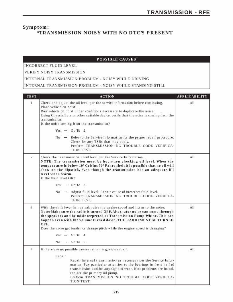
Symptom:*TRANSMISSION NOISY WITH NO DTC’S PRESENT
POSSIBLE CAUSES
INCORRECT FLUID LEVEL
VERIFY NOISY TRANSMISSION
INTERNAL TRANSMISSION PROBLEM - NOISY WHILE DRIVING
INTERNAL TRANSMISSION PROBLEM - NOISY WHILE STANDING STILL
TEST ACTION APPLICABILITY
1 Check and adjust the oil level per the service information before continuing.Place vehicle on hoist.Run vehicle on hoist under conditions necessary to duplicate the noise.Using Chassis Ears or other suitable device, verify that the noise is coming from thetransmission.Is the noise coming from the transmission?
All
Yes → Go To 2
No → Refer to the Service Information for the proper repair procedure.Check for any TSBs that may apply.Perform TRANSMISSION NO TROUBLE CODE VERIFICA-TION TEST.
2 Check the Transmission Fluid level per the Service Information.NOTE: The transmission must be hot when checking oil level. When thetemperature is below 10° Celsius 50° Fahrenheit it is possible that no oil willshow on the dipstick, even though the transmission has an adequate filllevel when warm.Is the fluid level OK?
All
Yes → Go To 3
No → Adjust fluid level. Repair cause of incorrect fluid level.Perform TRANSMISSION NO TROUBLE CODE VERIFICA-TION TEST.
3 With the shift lever in neutral, raise the engine speed and listen to the noise.Note: Make sure the radio is turned OFF. Alternator noise can come throughthe speakers and be misinterpreted as Transmission Pump Whine. This canhappen even with the volume turned down, THE RADIO MUST BE TURNEDOFF.Does the noise get louder or change pitch while the engine speed is changing?
All
Yes → Go To 4
No → Go To 5
4 If there are no possible causes remaining, view repair. All
RepairRepair internal transmission as necessary per the Service Infor-mation. Pay particular attention to the bearings in front half oftransmission and for any signs of wear. If no problems are found,replace the primary oil pump.Perform TRANSMISSION NO TROUBLE CODE VERIFICA-TION TEST.
219
TRANSMISSION - RFE

TEST ACTION APPLICABILITY
5 If there are no possible causes remaining, view repair. All
RepairRepair internal transmission as necessary per the Service Infor-mation. Inspect all of the transmission components for signs ofwear. Pay particular attention to bearings, pinion gears, etc.Repair or replace as necessary.Perform TRANSMISSION NO TROUBLE CODE VERIFICA-TION TEST.
220
TRANSMISSION - RFE
*TRANSMISSION NOISY WITH NO DTC’S PRESENT — Continued
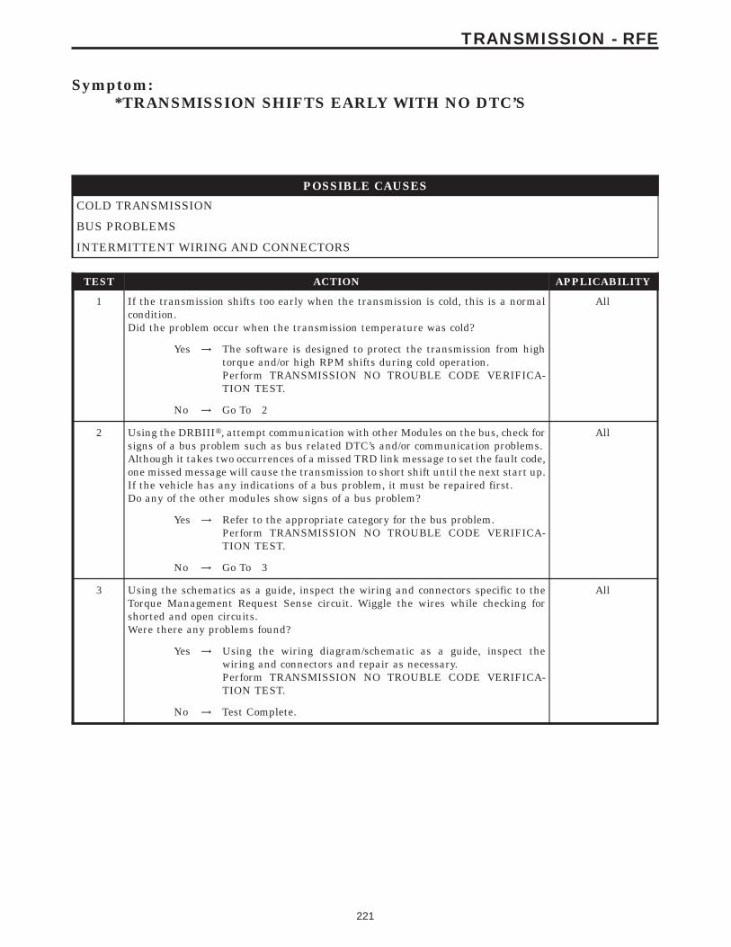
Symptom:*TRANSMISSION SHIFTS EARLY WITH NO DTC’S
POSSIBLE CAUSES
COLD TRANSMISSION
BUS PROBLEMS
INTERMITTENT WIRING AND CONNECTORS
TEST ACTION APPLICABILITY
1 If the transmission shifts too early when the transmission is cold, this is a normalcondition.Did the problem occur when the transmission temperature was cold?
All
Yes → The software is designed to protect the transmission from hightorque and/or high RPM shifts during cold operation.Perform TRANSMISSION NO TROUBLE CODE VERIFICA-TION TEST.
No → Go To 2
2 Using the DRBIIIt, attempt communication with other Modules on the bus, check forsigns of a bus problem such as bus related DTC’s and/or communication problems.Although it takes two occurrences of a missed TRD link message to set the fault code,one missed message will cause the transmission to short shift until the next start up.If the vehicle has any indications of a bus problem, it must be repaired first.Do any of the other modules show signs of a bus problem?
All
Yes → Refer to the appropriate category for the bus problem.Perform TRANSMISSION NO TROUBLE CODE VERIFICA-TION TEST.
No → Go To 3
3 Using the schematics as a guide, inspect the wiring and connectors specific to theTorque Management Request Sense circuit. Wiggle the wires while checking forshorted and open circuits.Were there any problems found?
All
Yes → Using the wiring diagram/schematic as a guide, inspect thewiring and connectors and repair as necessary.Perform TRANSMISSION NO TROUBLE CODE VERIFICA-TION TEST.
No → Test Complete.
221
TRANSMISSION - RFE
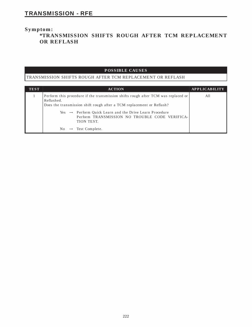
Symptom:*TRANSMISSION SHIFTS ROUGH AFTER TCM REPLACEMENTOR REFLASH
POSSIBLE CAUSES
TRANSMISSION SHIFTS ROUGH AFTER TCM REPLACEMENT OR REFLASH
TEST ACTION APPLICABILITY
1 Perform this procedure if the transmission shifts rough after TCM was replaced orReflashed.Does the transmission shift rough after a TCM replacement or Reflash?
All
Yes → Perform Quick Learn and the Drive Learn ProcedurePerform TRANSMISSION NO TROUBLE CODE VERIFICA-TION TEST.
No → Test Complete.
222
TRANSMISSION - RFE

Symptom:*TRANSMISSION SIMULATOR WILL NOT POWER UP
TEST ACTION APPLICABILITY
1 NOTE: If the Transmission Simulator, Miller tool #8333 will not power up,this is a symptom of the Transmission Control Relay being open, such asLimp-in, and/or the Simulator is not installed correctly on the vehicle.Note: Check the simulator ground cable connection.Repair these symptoms before having the Transmission Simulator, Miller tool #8333,repaired.
All
ContinueTest Complete.
223
TRANSMISSION - RFE
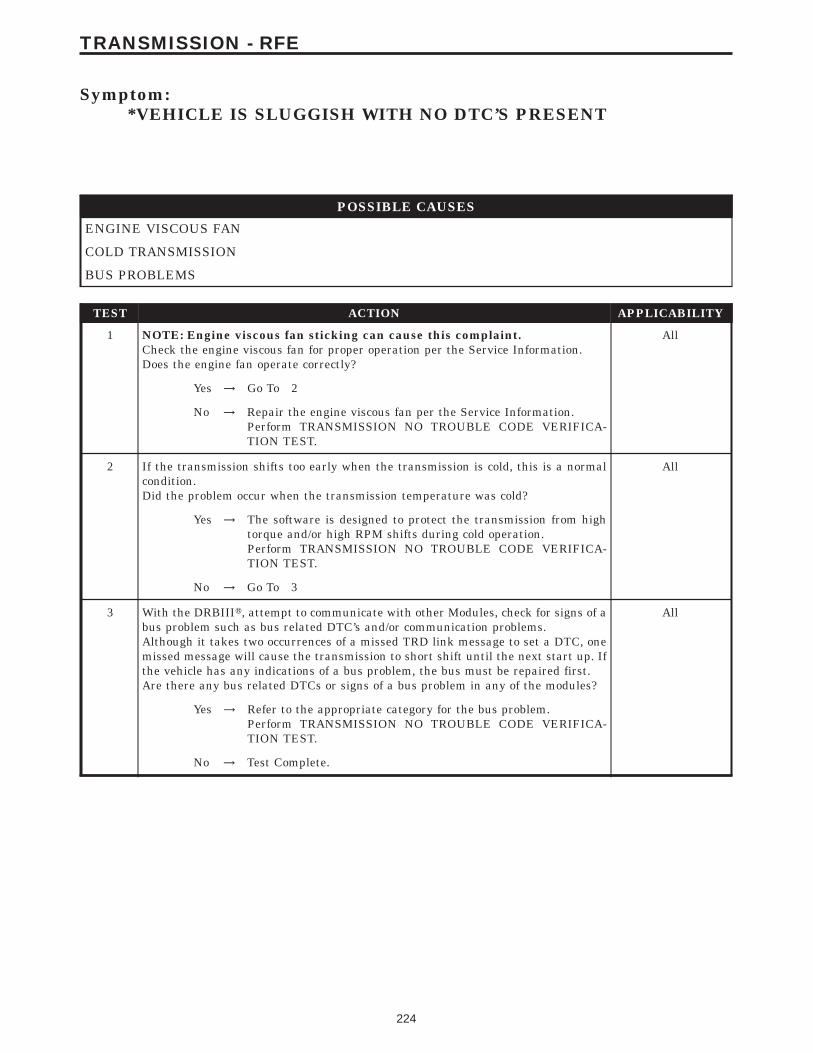
Symptom:*VEHICLE IS SLUGGISH WITH NO DTC’S PRESENT
POSSIBLE CAUSES
ENGINE VISCOUS FAN
COLD TRANSMISSION
BUS PROBLEMS
TEST ACTION APPLICABILITY
1 NOTE: Engine viscous fan sticking can cause this complaint.Check the engine viscous fan for proper operation per the Service Information.Does the engine fan operate correctly?
All
Yes → Go To 2
No → Repair the engine viscous fan per the Service Information.Perform TRANSMISSION NO TROUBLE CODE VERIFICA-TION TEST.
2 If the transmission shifts too early when the transmission is cold, this is a normalcondition.Did the problem occur when the transmission temperature was cold?
All
Yes → The software is designed to protect the transmission from hightorque and/or high RPM shifts during cold operation.Perform TRANSMISSION NO TROUBLE CODE VERIFICA-TION TEST.
No → Go To 3
3 With the DRBIIIt, attempt to communicate with other Modules, check for signs of abus problem such as bus related DTC’s and/or communication problems.Although it takes two occurrences of a missed TRD link message to set a DTC, onemissed message will cause the transmission to short shift until the next start up. Ifthe vehicle has any indications of a bus problem, the bus must be repaired first.Are there any bus related DTCs or signs of a bus problem in any of the modules?
All
Yes → Refer to the appropriate category for the bus problem.Perform TRANSMISSION NO TROUBLE CODE VERIFICA-TION TEST.
No → Test Complete.
224
TRANSMISSION - RFE
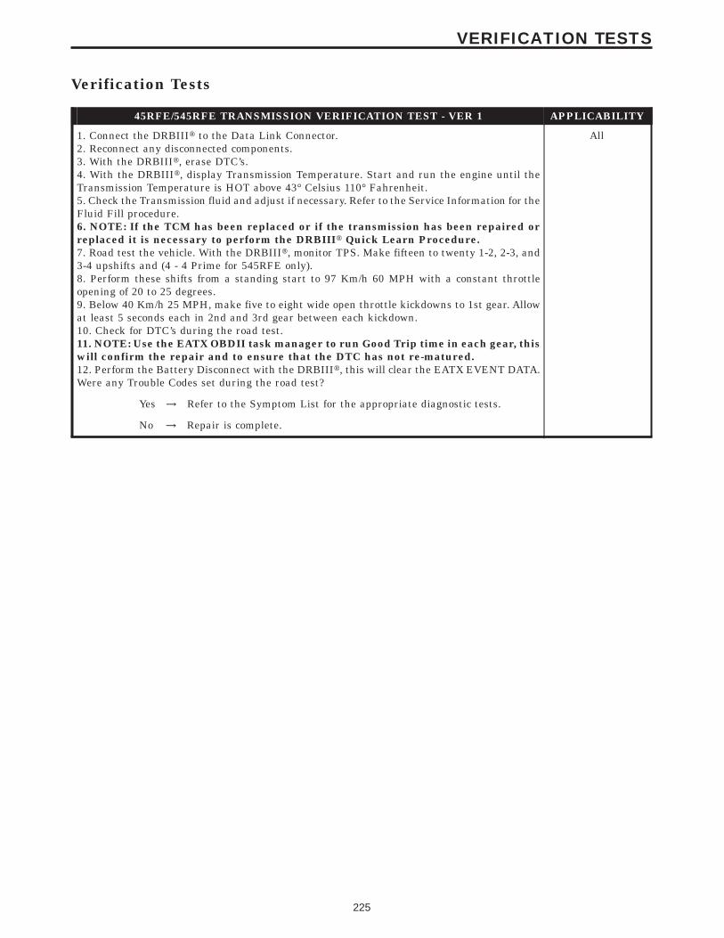
Verification Tests
45RFE/545RFE TRANSMISSION VERIFICATION TEST - VER 1 APPLICABILITY
1. Connect the DRBIIIt to the Data Link Connector.2. Reconnect any disconnected components.3. With the DRBIIIt, erase DTC’s.4. With the DRBIIIt, display Transmission Temperature. Start and run the engine until theTransmission Temperature is HOT above 43° Celsius 110° Fahrenheit.5. Check the Transmission fluid and adjust if necessary. Refer to the Service Information for theFluid Fill procedure.6. NOTE: If the TCM has been replaced or if the transmission has been repaired orreplaced it is necessary to perform the DRBIIIt Quick Learn Procedure.7. Road test the vehicle. With the DRBIIIt, monitor TPS. Make fifteen to twenty 1-2, 2-3, and3-4 upshifts and (4 - 4 Prime for 545RFE only).8. Perform these shifts from a standing start to 97 Km/h 60 MPH with a constant throttleopening of 20 to 25 degrees.9. Below 40 Km/h 25 MPH, make five to eight wide open throttle kickdowns to 1st gear. Allowat least 5 seconds each in 2nd and 3rd gear between each kickdown.10. Check for DTC’s during the road test.11. NOTE: Use the EATX OBDII task manager to run Good Trip time in each gear, thiswill confirm the repair and to ensure that the DTC has not re-matured.12. Perform the Battery Disconnect with the DRBIIIt, this will clear the EATX EVENT DATA.Were any Trouble Codes set during the road test?
All
Yes → Refer to the Symptom List for the appropriate diagnostic tests.
No → Repair is complete.
225
VERIFICATION TESTS
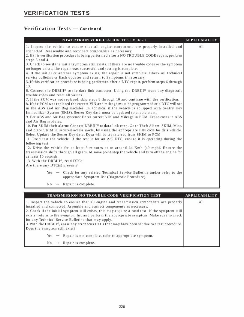
POWERTRAIN VERIFICATION TEST VER - 2 APPLICABILITY
1. Inspect the vehicle to ensure that all engine components are properly installed andconnected. Reassemble and reconnect components as necessary.2. If this verification procedure is being performed after a NO TROUBLE CODE repair, performsteps 3 and 4.3. Check to see if the initial symptom still exists. If there are no trouble codes or the symptomno longer exists, the repair was successful and testing is complete.4. If the initial or another symptom exists, the repair is not complete. Check all technicalservice bulletins or flash updates and return to Symptoms if necessary.5. If this verification procedure is being performed after a DTC repair, perform steps 6 through13.6. Connect the DRBIIIt to the data link connector. Using the DRBIIIt erase any diagnostictrouble codes and reset all values.7. If the PCM was not replaced, skip steps 8 through 10 and continue with the verification.8. If the PCM was replaced the correct VIN and mileage must be programmed or a DTC will setin the ABS and Air Bag modules. In addition, if the vehicle is equipped with Sentry KeyImmobilizer System (SKIS), Secret Key data must be updated to enable start.9. For ABS and Air Bag systems: Enter correct VIN and Mileage in PCM. Erase codes in ABSand Air Bag modules.10. For SKIM theft alarm: Connect DRBIIIt to data link conn. Go to Theft Alarm, SKIM, Misc.and place SKIM in secured access mode, by using the appropriate PIN code for this vehicle.Select Update the Secret Key data. Data will be transferred from SKIM to PCM11. Road test the vehicle. If the test is for an A/C DTC, ensure it is operating during thefollowing test.12. Drive the vehicle for at least 5 minutes at or around 64 Kmh (40 mph). Ensure thetransmission shifts through all gears. At some point stop the vehicle and turn off the engine forat least 10 seconds.13. With the DRBIIIt, read DTCs.Are there any DTC(s) present?
All
Yes → Check for any related Technical Service Bulletins and/or refer to theappropriate Symptom list (Diagnostic Procedure).
No → Repair is complete.
TRANSMISSION NO TROUBLE CODE VERIFICATION TEST APPLICABILITY
1. Inspect the vehicle to ensure that all engine and transmission components are properlyinstalled and connected. Assemble and connect components as necessary.2. Check if the initial symptom still exists, this may require a road test. If the symptom stillexists, return to the symptom list and perform the appropriate symptom. Make sure to checkfor any Technical Service Bulletins that may apply.3. With the DRBIIIt, erase any erroneous DTCs that may have been set due to a test procedure.Does the symptom still exist?
All
Yes → Repair is not complete, refer to appropriate symptom.
No → Repair is complete.
226
VERIFICATION TESTS
Verification Tests — Continued

8.0 COMPONENT LOCATIONS
8.1 ENGINE CONTROL MODULE LOCATIONS
8.2 TRANSMISSION CONTROL MODULE LOCATIONS
8.3 TRANSMISSION COMPONENT LOCATIONS
COMPONENT
LOCATIONS
227
COMPONENT LOCATIONS
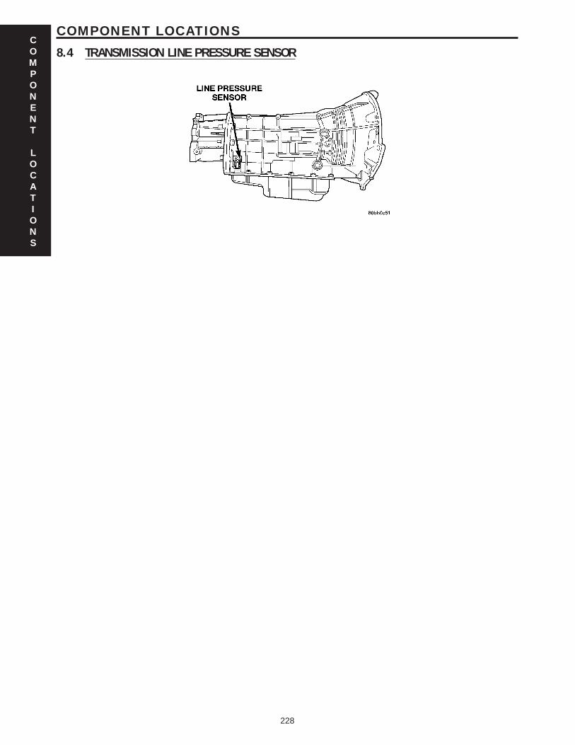
8.4 TRANSMISSION LINE PRESSURE SENSORCOMPONENT
LOCATIONS
228
COMPONENT LOCATIONS

9.0 CONNECTOR PINOUTS
DATA LINK CONNECTOR - BLACK 16 WAYCAV CIRCUIT FUNCTION
1 - -
2 D25 20WT/VT PCI BUS
3 - -
4 Z11 20BK/LG GROUND
5 Z11 20BK/LG GROUND
6 - -
7 D21 20WT/GY (DIESEL) SCI TRANSMIT (ECM)
7 D21 20WT/GY (GAS) SCI TRANSMIT (PCM)
8 - -
9 D16 20WT/OR SCI RECEIVE (TCM)
10 - -
11 - -
12 D20 20WT/LG (DIESEL) SCI RECEIVE (ECM)
12 D20 20WT/LG (GAS) SCI RECEIVE (PCM)
13 - -
14 - -
15 D15 20BR/WT SCI TRANSMIT (TCM)
16 A333 20WT/RD FUSED B(+)
INPUT SPEED SENSOR (A/T) - BLACK 2 WAYCAV CIRCUIT FUNCTION
1 T52 20DG/WT INPUT SPEED SENSOR SIGNAL
2 T13 20DG/VT SPEED SENSOR GROUND
LINE PRESSURE SENSOR (2.8L 45RFE) - BLACK 4 WAYCAV CIRCUIT FUNCTION
1 Z133 20BK/LG GROUND
2 T39 20BR/YL 5 VOLT SUPPLY
3 T38 20YL/BR LINE PRESSURE SENSOR SIGNAL
4 - -
CONNECTOR
PINOUTS
229
CONNECTOR PINOUTS
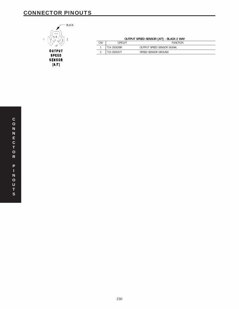
OUTPUT SPEED SENSOR (A/T) - BLACK 2 WAYCAV CIRCUIT FUNCTION
1 T14 20DG/BR OUTPUT SPEED SENSOR SIGNAL
2 T13 20DG/VT SPEED SENSOR GROUND
CONNECTOR
PINOUTS
230
CONNECTOR PINOUTS

CONNECTOR
PINOUTS
231
CONNECTOR PINOUTS

FUSES (GAS)FUSENO.
AMPS FUSED CIRCUIT FUNCTION
1 40A INTERNAL FUSED B(+)
2 30A INTERNAL FUSED B(+)
3 50A A912 10RD FUSED B(+)
4 40A A107 12TN/RD (ABS) FUSED B(+)
5 20A INTERNAL FUSED B(+)
6 30A INTERNAL FUSED B(+)
7 50A A911 10RD FUSED B(+)
8 40A A916 12RD FUSED B(+)
9 50A A901 10RD FUSED B(+)
10 30A A100 14RD/VT FUSED B(+)
11 - - -
12 30A A904 14RD FUSED B(+)
13 40A A139 12RD/YL FUSED B(+)
14 40A A1 12RD FUSED B(+)
15 50A A12 10RD/BR FUSED B(+)
16 - - -
17 - - -
18 - - -
19 30A A906 12RD FUSED B(+)
20 - - -
21 20A INTERNAL FUSED B(+)
22 - - -
23 - - -
24 20A A209 18RD FUSED B(+)
25 20A A200 12RD/DG (ABS) FUSED B(+)
26 15A F142 16PK/GY FUSED ASD RELAY OUTPUT
27 - - -
28 15A INTERNAL FUSED IGNITION SWITCH OUTPUT (START)
TRANSMISSION CONTROL RELAY (A/T)CAV CIRCUIT FUNCTION
30 INTERNAL FUSED B(+)
30 A903 16RD (DIESEL) FUSED B(+)
85 Z932 20BK GROUND
86 T515 20YL/DB TRANSMISSION CONTROL RELAY CONTROL
87 T16 16YL/OR TRANSMISSION CONTROL RELAY OUTPUT
87A - -
CONNECTOR
PINOUTS
232
CONNECTOR PINOUTS
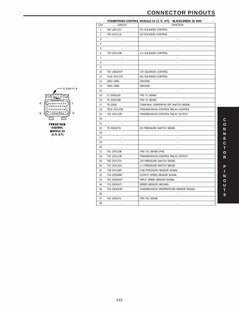
POWERTRAIN CONTROL MODULE C4 (3.7L A/T) - BLACK/GREEN 38 WAYCAV CIRCUIT FUNCTION
1 T60 18YL/GY OD SOLENOID CONTROL
2 T59 18YL/LB UD SOLENOID CONTROL
3 - -
4 - -
5 - -
6 T19 18YL/DB 2-4 SOLENOID CONTROL
7 - -
8 - -
9 - -
10 T20 18DG/WT L/R SOLENOID CONTROL
11 T140 20YL/GY MS SOLENOID CONTROL
12 Z903 16BK GROUND
13 Z903 16BK GROUND
14 - -
15 T1 20DG/LB TRS T1 SENSE
16 T3 20DG/DB TRS T3 SENSE
17 T6 20DG TOW/HAUL OVERDRIVE OFF SWITCH SENSE
18 T515 20YL/DB TRANSMISSION CONTROL RELAY CONTROL
19 T16 16YL/OR TRANSMISSION CONTROL RELAY OUTPUT
20 - -
21 - -
22 T9 20DG/TN OD PRESSURE SWITCH SENSE
23 - -
24 - -
25 - -
26 - -
27 T41 20YL/DB TRS T41 SENSE (P/N)
28 T16 16YL/OR TRANSMISSION CONTROL RELAY OUTPUT
29 T50 20YL/TN L/R PRESSURE SWITCH SENSE
30 T47 20YL/DG 2-4 PRESSURE SWITCH SENSE
31 T38 20YL/BR LINE PRESSURE SENSOR SIGNAL
32 T14 20DG/BR OUTPUT SPEED SENSOR SIGNAL
33 T52 20DG/WT INPUT SPEED SENSOR SIGNAL
34 T13 20DG/VT SPEED SENSOR GROUND
35 T54 20DG/OR TRANSMISSION TEMPERATURE SENSOR SIGNAL
36 - -
37 T42 20DG/YL TRS T42 SENSE
38 - -
CONNECTOR
PINOUTS
233
CONNECTOR PINOUTS
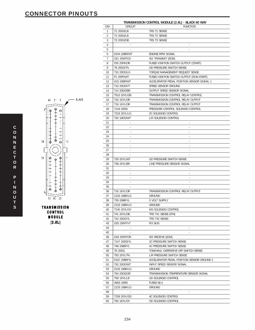
TRANSMISSION CONTROL MODULE (2.8L) - BLACK 60 WAYCAV CIRCUIT FUNCTION
1 T1 20DG/LB TRS T1 SENSE
2 T4 20DG/LB TRS T2 SENSE
3 T3 20DG/DB TRS T3 SENSE
4 - -
5 - -
6 K244 20BR/WT ENGINE RPM SIGNAL
7 D21 20WT/GY SCI TRANSMIT (ECM)
8 F26 20PK/OR FUSED IGNITION SWITCH OUTPUT (START)
9 T9 20DG/TN OD PRESSURE SWITCH SENSE
10 T10 20DG/LG TORQUE MANAGEMENT REQUEST SENSE
11 F1 20PK/WT FUSED IGNITION SWITCH OUTPUT (RUN-START)
12 K23 20BR/WT ACCELERATOR PEDAL POSITION SENSOR SIGNAL 1
13 T13 20DG/VT SPEED SENSOR GROUND
14 T14 20DG/BR OUTPUT SPEED SENSOR SIGNAL
15 T515 20YL/DB TRANSMISSION CONTROL RELAY CONTROL
16 T16 16YL/OR TRANSMISSION CONTROL RELAY OUTPUT
17 T16 16YL/OR TRANSMISSION CONTROL RELAY OUTPUT
18 T118 20DG PRESSURE CONTROL SOLENOID CONTROL
19 T219 20YL/LG 2C SOLENOID CONTROL
20 T20 18DG/WT L/R SOLENOID CONTROL
21 - -
22 - -
23 - -
24 - -
25 - -
26 - -
27 - -
28 - -
29 T29 20YL/WT UD PRESSURE SWITCH SENSE
30 T38 20YL/BR LINE PRESSURE SENSOR SIGNAL
31 - -
32 - -
33 - -
34 - -
35 - -
36 T16 16YL/OR TRANSMISSION CONTROL RELAY OUTPUT
37 Z133 16BK/LG GROUND
38 T39 20BR/YL 5 VOLT SUPPLY
39 Z133 16BK/LG GROUND
40 T140 20YL/GY MS SOLENOID CONTROL
41 T41 20YL/DB TRS T41 SENSE (P/N)
42 T42 20DG/YL TRS T42 SENSE
43 D25 20WT/VT PCI BUS
44 - -
45 - -
46 D16 20WT/OR SCI RECEIVE (ECM)
47 T147 20DG/YL 2C PRESSURE SWITCH SENSE
48 T48 20BR/YL 4C PRESSURE SWITCH SENSE
49 T6 20DG TOW/HAUL OVERDRIVE OFF SWITCH SENSE
50 T50 20YL/TN L/R PRESSURE SWITCH SENSE
51 K167 20BR/YL ACCELERATOR PEDAL POSITION SENSOR GROUND 1
52 T52 20DG/WT INPUT SPEED SENSOR SIGNAL
53 Z133 16BK/LG GROUND
54 T54 20DG/OR TRANSMISSION TEMPERATURE SENSOR SIGNAL
55 T59 18YL/LB UD SOLENOID CONTROL
56 A903 16RD FUSED B(+)
57 Z133 16BK/LG GROUND
58 - -
59 T159 20YL/DG 4C SOLENOID CONTROL
60 T60 18YL/GY OD SOLENOID CONTROL
CONNECTOR
PINOUTS
234
CONNECTOR PINOUTS

TRANSMISSION RANGE SENSOR (42RLE) - 10 WAYCAV CIRCUIT FUNCTION
1 C115 20DB FUSED IGNITION SWITCH OUTPUT (RUN)
2 - -
3 T13 20DG/VT SPEED SENSOR GROUND
4 T54 20DG/OR TRANSMISSION TEMPERATURE SENSOR SIGNAL
5 - -
6 L10 20WT/GY BACK-UP LAMP FEED
7 T1 20DG/LB TRS T1 SENSE
8 T3 20DG/DB TRS T3 SENSE
9 T42 20DG/YL TRS T42 SENSE
10 T41 20YL/DB TRS T41 SENSE (P/N)
TRANSMISSION SOLENOID/PRESSURE SWITCH ASSEMBLY (42RLE) - 10 WAYCAV CIRCUIT FUNCTION
1 T60 18YL/GY OD SOLENOID CONTROL
2 T59 18YL/LB UD SOLENOID CONTROL
3 T16 16YL/OR TRANSMISSION CONTROL RELAY OUTPUT
4 T19 18YL/DB 2-4 SOLENOID CONTROL
5 T47 20YL/DG 2-4 PRESSURE SWITCH SENSE
6 T9 20DG/TN OD PRESSURE SWITCH SENSE
7 T20 18DG/WT L/R SOLENOID CONTROL
8 - -
9 - -
10 T50 20YL/TN L/R PRESSURE SWITCH SENSE
TRANSMISSION SOLENOID/TRS ASSEMBLY (2.8L 45RFE) - GRAY 23 WAYCAV CIRCUIT FUNCTION
1 C115 20DB FUSED IGNITION SWITCH OUTPUT (RUN)
2 T20 18DG/WT L/R SOLENOID CONTROL
3 T41 20YL/DB TRS T41 SENSE (P/N)
4 T41 20YL/DB TRS T41 SENSE (P/N)
5 T42 20DG/YL TRS T42 SENSE
6 L10 20WT/GY BACK-UP LAMP FEED
7 T60 18YL/GY OD SOLENOID CONTROL
8 T3 20DG/DB TRS T3 SENSE
9 T1 20DG/LB TRS T1 SENSE
10 T16 16YL/OR TRANSMISSION CONTROL RELAY OUTPUT
11 T48 20BR/YL 4C PRESSURE SWITCH SENSE
12 T118 20DG PRESSURE CONTROL SOLENOID CONTROL
13 T4 20DG/LB TRS T2 SENSE
14 T50 20YL/TN L/R PRESSURE SWITCH SENSE
15 T147 20DG/YL 2C PRESSURE SWITCH SENSE
16 T9 20DG/TN OD PRESSURE SWITCH SENSE
17 T59 18YL/LB UD SOLENOID CONTROL
18 T29 20YL/WT UD PRESSURE SWITCH SENSE
19 T159 20YL/DG 4C SOLENOID CONTROL
20 T219 20YL/LG 2C SOLENOID CONTROL
21 T140 20YL/GY MS SOLENOID CONTROL
22 T13 20DG/VT SPEED SENSOR GROUND
23 T54 20DG/OR TRANSMISSION TEMPERATURE SENSOR SIGNAL
CONNECTOR
PINOUTS
235
CONNECTOR PINOUTS

NOTES
236
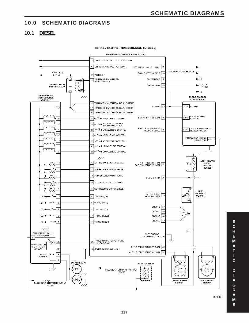
10.0 SCHEMATIC DIAGRAMS
10.1 DIESEL
SCHEMATIC
DIAGRAMS
237
SCHEMATIC DIAGRAMS

NOTES
238
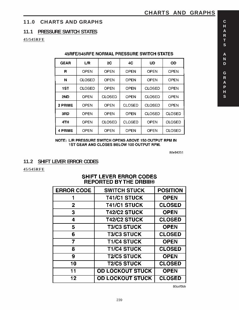
11.0 CHARTS AND GRAPHS
11.1 PRESSURE SWITCH STATES45/545RFE
11.2 SHIFT LEVER ERROR CODES45/545RFE
CHARTS
AND
GRAPHS
239
CHARTS AND GRAPHS
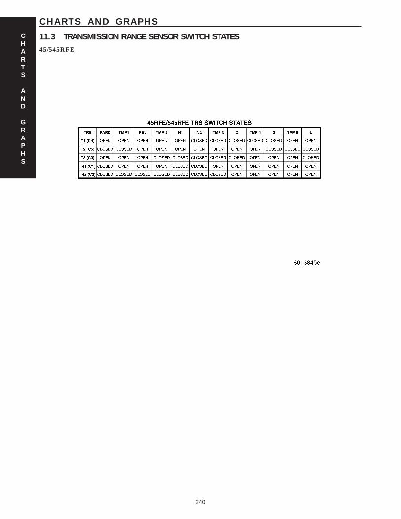
11.3 TRANSMISSION RANGE SENSOR SWITCH STATES45/545RFE
CHARTS
AND
GRAPHS
240
CHARTS AND GRAPHS

DIAGNOSTIC TEST PROCEDURES — TELL US!
DaimlerChrysler Corporation is constantly working to provide the technician the best diagnostic manuals possible.Your comments and recommendations regarding the diagnostic manuals and procedures are appreciated.
To best understand your suggestion, please complete the form giving us as much detail as possible.
Model Year Body Type Engine
Transmission Vehicle Mileage MDH
Diagnostic Procedure Book No. Page
Comments/recommendations (if necessary, draw sketch)
Name
Submitted by:
Address
City/State/Zip
Business Phone #
All comments become property of DaimlerChrysler Corporation and may be used without compensation.
Dealer Technical Operations800 Chrysler DriveCIMS 486-02-76Auburn Hills, MI 48326-2757