table of contents - fordservicecontent.com · according to the eot and baro sensors. the required...
TRANSCRIPT
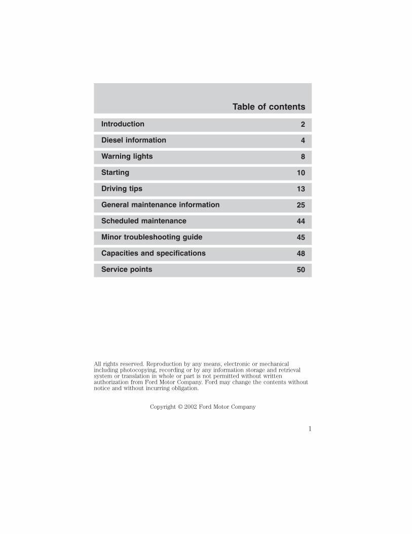
Introduction 2
Diesel information 4
Warning lights 8
Starting 10
Driving tips 13
General maintenance information 25
Scheduled maintenance 44
Minor troubleshooting guide 45
Capacities and specifications 48
Service points 50
All rights reserved. Reproduction by any means, electronic or mechanicalincluding photocopying, recording or by any information storage and retrievalsystem or translation in whole or part is not permitted without writtenauthorization from Ford Motor Company. Ford may change the contents withoutnotice and without incurring obligation.
Copyright © 2002 Ford Motor Company
Table of contents
1

California Proposition 65 Warning: Diesel engine exhaust, someof its constituents, and certain vehicle components contain or
may emit chemicals known to the State of California to cause cancer orbirth defects or other reproductive harm.
Your new Diesel engine will feel, drive and function somewhat differentlythan a gasoline engine. Therefore it is very important that you read andthoroughly familiarize yourself and others operating the vehicle with thisguide.This guide will acquaint you with the Power Stroke (7.3L DIT) Dieselengine. It provides recommendations on engine care and operatingprocedures. For complete vehicle information, also refer to the OwnerGuide included with the vehicle. It also describes equipment and givesspecifications for equipment that was in effect when this guide wasapproved for printing, and should be considered a permanent part of thevehicle.Some aftermarket products may cause severe engine and/ortransmission damage. There are various manufacturers offeringdevices to increase turbocharger boost, exhaust brakes toincrease stopping/hauling capacity or other such devices toincrease the power/torque of the 7.3L engine. Many owners’ pastexperience with these products has been very poor. Severepowertrain damage may result from the use of these aftermarketproducts which will not be covered by the Ford warranty.
Ford may discontinue models or change specifications without any noticeand without incurring obligations.
IMPORTANT NOTICEFord vehicles are suitable for producing ambulances only if equippedwith the Ford Ambulance Preparation Package. In addition, Fordurges ambulance manufacturers to follow the recommendation of theFord Incomplete Vehicle Manual, Ford Truck Body Builder’s LayoutBook (and pertinent supplements) and the Qualified Vehicle ModifiersGuidelines. Using a Ford vehicle without the Ford AmbulancePreparation Package to produce an ambulance voids the Ford warrantyand could result in elevated underbody temperatures, fueloverpressurization and the risk of fuel expulsion and fires. To determinewhether the vehicle is equipped with the Ford Ambulance PreparationPackage, inspect the information plate on the driver’s side door pillar.Contact the manufacturer of your vehicle to determine whether theambulance manufacturer’s followed Ford’s recommendations.
Introduction
2

WARNING: Engine exhaust, some of its constituents, andcertain vehicle components contain or emit chemicals known to
the State of California to cause cancer and birth defects or otherreproductive harm. Certain fluids contained in vehicles and certainproducts of components contain or emit chemicals known to the Stateof California to cause cancer and birth defects or other reproductiveharm.
WARNINGSThroughout this guide, you will find warnings. Warnings remind you tobe especially careful to avoid personal injury.
NEW VEHICLE BREAK-INYour vehicle does not need an extensive break-in. Try not to drivecontinuously at the same speed for the first 1,600 km (1,000 miles) ofnew vehicle operation. Vary your speed to allow parts to adjustthemselves to other parts.
Drive your new vehicle at least 800 km (500 miles) before towing atrailer.
Do not add friction modifier compounds or special break-in oils duringthe first few thousand kilometers (miles) of operation, since theseadditives may prevent piston ring seating. See Engine oil in the GeneralMaintenance Information chapter for more information on oil usage.
Introduction
3

DIESEL ENGINE INFORMATIONThe Diesel engine fuel system consists of:• a frame-mounted electric fuel supply pump• an engine mounted fuel filter/water separator• a fuel restriction sensor• a unit injector for each cylinderThe combination fuel filter/water separator removes both water andimpurities from the fuel. The filter should be changed at therecommended service interval. Refer to the scheduled maintenance guidefor more information. The filter bowl should be drained at regularintervals or when the WATER IN FUEL light illuminates in theinstrument cluster.
The fuel injectors are located in the center of the combustion chambersin the cylinder head between the rocker arm assemblies. The glow plugsystem and fuel injection system are controlled through the PowertrainControl Module (PCM).
Fuel is drawn from the fuel tank by a frame-mounted electric fuel pump.The fuel pump provides pressurized fuel to the engine and iselectronically controlled by the fuel pump PCM relay. The fuel pumpcontains a pressure relief valve for overpressure protection in the eventof restricted flow.
Lubrication systemIt is important to change the engine oil at the recommended serviceintervals, because oil viscosity is important in maintaining the oilpressure required to actuate the fuel injectors. Extended oil changeintervals can negatively affect engine performance and fuel economy.
Pressurized oil from the turbocharger is also used to actuate an exhaustbackpressure warm-up system (if equipped). Pressurized oil from theturbocharger is routed to the exhaust backpressure actuator. Duringexhaust backpressure operation, the engine’s sound will be altered andyou may notice a change in engine performance while it’s engaged. Thisfunction occurs only during cold weather warm-up cycle.
Fast start glow plug systemThe glow plug system consists of:
• eight glow plugs
• the glow plug relay
Diesel information
4

• engine oil temperature (EOT) sensor
• barometric pressure (BARO) sensor
The glow plug system is electronically controlled by the PCM. The PCMenergizes the glow plugs immediately after the ignition is placed in theON position, then determines how long the glow plugs will be onaccording to the EOT and BARO sensors. The required time for the glowplugs to be energized decreases as the engine oil temperature andbarometric pressure increase.
Engine cooling system
The cooling system contains an engine oil cooler which is mounted tothe side of the cylinder block. The cooler’s function is to regulate engineoil temperature.
Engine governed speed
The engine governor is controlled by the PCM. The PCM controls fuelinput to limit maximum engine speed. It will not, however, preventengine overspeeding resulting from downshifting at high vehicle speed orby descending steep grades at too high a vehicle speed for the selectedtransmission gear.
For maximum vehicle speed in various gears, refer to Manualtransmission shift speeds in the Driving tips chapter. Do not exceed3,600 rpm. Maximum engine governed speed is 3,000–4,000 rpmdepending on engine load. Excessive rpm can only be achieved bymanually downshifting at too high of a vehicle speed.
Operating the engine beyond the governed speed can cause severeengine damage.
Air filter restriction gauge, E-SeriesThe restriction gauge, located onthe clean-air side of the air cleanerupper housing, shows if the air filteris clogged. Refer to EngineCompartment in Service pointschapter.
AIR FILTER GAUGE
CHANGE FILTER CHANGE FILTER
Diesel information
5

The air filter element should bereplaced when the colored band onthe gauge reaches the CHANGEFILTER mark. Engine performanceand fuel economy are adverselyaffected when maximum restrictionis reached. After servicing the airfilter element, reset the restrictiongauge by pressing the button on theend of the gauge.
Air filter restriction gauge, F-250/350/450/550 & ExcursionThe restriction gauge, located onthe upper housing of the air cleanerassembly, monitors the condition ofthe air filter element in two ways:
First, the colored indictor inside thegauge highlights the percentage thatthe air filter element is clogged withdust or contaminants. Refer toEngine Compartment in ServicePoints chapter.
Second, the gauge contains an electrical switch which illuminates awarning light on the instrument cluster when the air filter element is100% clogged. Refer to F-250/350/450/550, Excursion in WarningLights chapter.
Check the air filter restriction gauge whenever the hood is raised toperform general engine maintenance. If the vehicle is operated inextremely dusty conditions, check the gauge at least every 800 km (500miles), or two weeks, whichever comes first.
The air filter element must bereplaced when the colored band onthe gauge reaches the CHANGEFILTER mark. Engine performanceand fuel economy are adverselyaffected when the maximumrestriction is reached.
AIR FILTER GAUGE
CHANGE FILTER CHANGE FILTER
Diesel information
6

Blowing-out the air filter element with compressed air is notrecommended as the compressed air may damage the filter paper.
Note: It is not possible to determine the level of filter clogging by visualappearance alone. A filter which appears to be dirty may actually haveseveral thousand kilometers (miles) of life remaining.
Always use the underhood air filter restriction gauge or engineair filter warning light on the instrument cluster to determinewhen the air filter element needs to be changed.
After servicing the air filter element,reset the restriction gauge bypressing the button on the end ofthe gauge.
Note: If the vehicle is operated in a heavy snow storm, in blowing snowor the vehicle is equipped with a snowplow, the engine air filter elementmay become partially clogged with snow and/or ice. If this occurs, the airfilter restriction gauge will move to the CHANGE FILTER mark and theengine may experience a significant reduction in power output. Thevehicle may be driven under these conditions for up to 160 km (100miles) without damage to the engine or related components.
At the earliest opportunity, clear all snow and ice from the air inductionsystem and replace the air filter element, or remove the element and dryit out. Reset the restriction gauge by pressing the button on the end ofthe gauge.
The air filter warning light on the instrument cluster may be used, inaddition to the underhood restriction gauge, to monitor the condition ofthe air filter element. Refer to the Warning Lights chapter.
Diesel information
7

E-SERIES
F–250/350/450/550, EXCURSION
WAIT TO START• E-Series
• F-250/350/450/550, Excursion
With the key in the ON position, the WAIT TO START light willilluminate if glow plug heat is necessary as a starting aid. Wait until thelight goes off before starting. The light should always illuminate briefly,when the ignition key is in the ON position. If the light does notilluminate, there may be a problem. Refer to the Starting chapter in thisguide. After the engine starts, the light should remain off.The light should always illuminate at least momentarily when the engineis cold and the ignition is turned to ON. If it does not illuminate, theglow plug system should be checked and repaired promptly to avoiddifficulty in cold starting.
Warning lights
8

WATER IN FUEL• E-Series
• F-250/350/450/550, Excursion
During refueling, it is possible for water-contaminated diesel fuel to bepumped into your tank. Your vehicle fuel system is equipped with a fuelfilter/water separator to remove water from the fuel. The WATER INFUEL light will illuminate when the ignition is turned to START (as partof the light function check) and when the fuel filter/water separator hasa significant quantity of water in it.
If the light illuminates when the engine is running, stop the vehicle assoon as safely possible, shut off the engine, then drain the filter bowl.Refer to the General maintenance chapter for drain procedure.Allowing water to stay in the system could result in extensive damage to,or failure of, the fuel injection system.
Do not drain the water separator while the engine is running.Fuel may ignite if the separator is drained while the engine is
running or the vehicle is moving.
ENGINE AIR FILTER (F-250/350/450/550 & EXCURSION)The engine air filter warning lightilluminates when the air filterrestriction gauge reaches theCHANGE FILTER mark.
The vehicle may be driven with the engine air filter warning lightilluminated for up to 400 km (250 miles) without damaging the engine orrelated components. However, the air filter element must be replaced atthe earliest opportunity. Refer to Air filter restriction gauge in theDiesel information chapter for more information.
Warning lights
9

STARTING THE ENGINERead all starting instructions carefully before you start your vehicle.
For temperatures below 0°C (32°F), the use of the correct grade engineoil is essential for proper operation.
If your vehicle is equipped with a manual transmission, make sure theparking brake is set fully before you turn the key. Depress the clutchpedal and place the gearshift in the neutral position. The clutch must befully depressed in order to operate the starter. Do not press theaccelerator during starting.
If your vehicle is equipped with an automatic transmission, ensure thegearshift lever is in P (Park) and the parking brake is set before you turnthe key. Do not press the accelerator during starting.
COLD WEATHER STARTINGDo not crank the engine for more than 30 seconds at a time as starterdamage may occur. If the engine fails to start, turn the key to OFF andwait 30 seconds before trying again.
Do not use starting fluid such as ether in the air intake system (see AirCleaner Decal). Such fluid could cause immediate explosive damage tothe engine and possible personal injury.
Do not add gasoline, gasohol or alcohol to Diesel fuel. This practicecreates a serious fire hazard and causes engine performance problems.
1. Make sure all vehicle occupants have buckled their safety belts. Formore information on safety belts and their proper usage, refer to Seatingand safety restraints chapter in the owner guide.
2. Make sure the headlamps and vehicle accessories are off.
3. Turn the key to the ON position. When the WAIT TO START lightgoes off, turn the key to START. (For Canadian vehicles, the daytimerunning lamps will be on if the parking brake is not applied and the keyis turned to ON.)
• E-Series
• F-250/350/450/550, Excursion
Starting
10

4. When the engine starts, release the key. The glow plugs will continueto be activated for up to two minutes. If the engine is not started beforethe activation ceases, the glow plug system must be reset by turning theignition key to OFF.
5. After the engine starts, allow it to idle for about 15 seconds. (Do notincrease engine speed until the oil pressure gauge indicates normalpressure.)
STOPPING THE ENGINETurn the ignition to OFF. To prolong engine life (after extended highspeed or maximum GVW operation), it is recommended that a hot enginebe allowed to operate at low idle for about 7–10 minutes which wouldallow sufficient time for the turbocharged engine to cool down.
COLD WEATHER OPERATIONChanging to a lighter grade engine oil also makes starting easier underthese conditions. Refer to Engine Oil Specifications in the Generalmaintenance information chapter.
At temperatures below –7°C (20°F), Number 2–D Diesel fuel maythicken enough to clog the fuel filter. Your engine is equipped with a fuelfilter/heater/water/separator to keep the wax melted which will helpprevent fuel filter clogging. However, if the engine starts but stalls after ashort time and will not restart, the fuel filter may be clogged. For bestresults in cold weather, use Number 1–D Diesel fuel or “winterized”Number 2–D Diesel fuel which has an additive to minimize waxformation.
Your vehicle is also equipped with a bypass relief valve, located on thein-tank fuel sending unit, which provides fuel flow to the engine if thefuel pickup should become plugged by ice or wax. To allow this bypassvalve to function and avoid engine fuel starvation, it is recommendedthat, during cold weather operation 0°C (32°F) or below, the fuel level inyour tank should not be allowed to drop below 1/4 full. This will helpprevent air from entering the fuel system and stalling the engine.
In cold weather below 0°C (32°F) your Diesel engine will slowly increaseto a higher idle speed if left idling in P (Park). The sound of the enginemay change also, as an exhaust device engages to improve heaterperformance and reduce exhaust smoke.
Starting
11

Operation in snowVehicle operation in heavy snowfall or in dry loose snow that may swirlaround the front of the vehicle may feed excessive amounts of snow intothe air intake system. This could plug the air cleaner with snow andcause the engine to stall.
Refer to Air filter restriction gauge in the Diesel information chapterand Engine air filter in the Warning lights chapter for more information.
Operation in standing waterIngestion of water into the Diesel engine can result in immediate andsevere damage to the engine. If driving through water, slow down toavoid splashing water into the intake. If the engine stalls, and ingestionof water into the engine is suspected, do not try to restart the engine.Consult your dealer for service immediately. Follow the cylindercompression test procedure outlined in the Workshop Manual, thencheck the engine oil for contamination.
Engine block heater (if equipped)Refer to the Starting chapter in your Owner Guide.
Starting
12
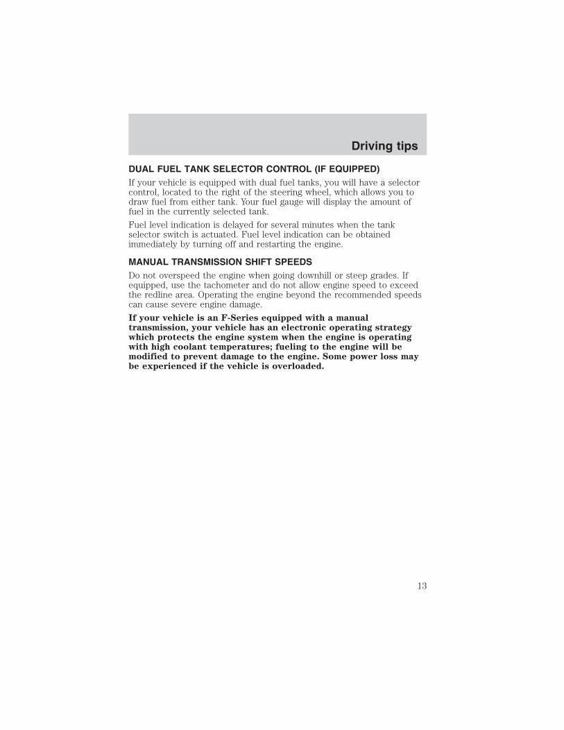
DUAL FUEL TANK SELECTOR CONTROL (IF EQUIPPED)If your vehicle is equipped with dual fuel tanks, you will have a selectorcontrol, located to the right of the steering wheel, which allows you todraw fuel from either tank. Your fuel gauge will display the amount offuel in the currently selected tank.
Fuel level indication is delayed for several minutes when the tankselector switch is actuated. Fuel level indication can be obtainedimmediately by turning off and restarting the engine.
MANUAL TRANSMISSION SHIFT SPEEDSDo not overspeed the engine when going downhill or steep grades. Ifequipped, use the tachometer and do not allow engine speed to exceedthe redline area. Operating the engine beyond the recommended speedscan cause severe engine damage.
If your vehicle is an F-Series equipped with a manualtransmission, your vehicle has an electronic operating strategywhich protects the engine system when the engine is operatingwith high coolant temperatures; fueling to the engine will bemodified to prevent damage to the engine. Some power loss maybe experienced if the vehicle is overloaded.
Driving tips
13
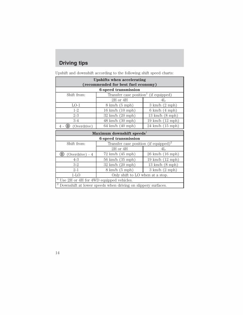
Upshift and downshift according to the following shift speed charts:
Upshifts when accelerating
(recommended for best fuel economy)
6-speed transmission
Shift from: Transfer case position1 (if equipped)2H or 4H 4L
LO-1 8 km/h (5 mph) 3 km/h (2 mph)1-2 16 km/h (10 mph) 6 km/h (4 mph)2-3 32 km/h (20 mph) 13 km/h (8 mph)3-4 48 km/h (30 mph) 19 km/h (12 mph)
4 - D (Overdrive) 64 km/h (40 mph) 24 km/h (15 mph)
Maximum downshift speeds1
6-speed transmission
Shift from: Transfer case position (if equipped)2
2H or 4H 4LD (Overdrive) - 4 72 km/h (45 mph) 26 km/h (16 mph)
4-3 56 km/h (35 mph) 19 km/h (12 mph)3-2 32 km/h (20 mph) 13 km/h (8 mph)2-1 8 km/h (5 mph) 3 km/h (2 mph)
1-LO Only shift to LO when at a stop.1 Use 2H or 4H for 4WD equipped vehicles.2 Downshift at lower speeds when driving on slippery surfaces.
Driving tips
14

TRAILER TOWING
Refer to your Owner Guide for full details on towing a trailer.
E-Series trailer towing tables
Your vehicle may tow a class I, II or III trailer provided the maximumtrailer weight is less than or equal to the maximum trailer weight listedfor your engine and rear axle ratio on the following charts.
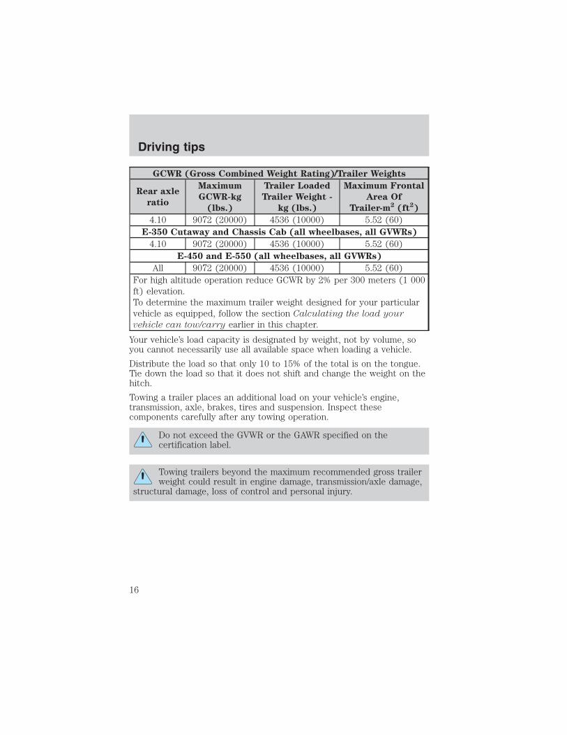
GCWR (Gross Combined Weight Rating)/Trailer Weights
Rear axle
ratio
Maximum
GCWR-kg
(lbs.)
Trailer Loaded
Trailer Weight -
kg (lbs.)
Maximum Frontal
Area Of
Trailer-m2 (ft2)
E-350 Regular Van (9500 GVWR)
3.55 7258 (16000) 4400 (9700) 5.52 (60)4.10 9072 (20000) 4536 (10000) 5.52 (60)
E-350 Regular Van (Crew) (9500 GVWR)
3.55 7258 (16000) 4309 (9500) 5.52 (60)4.10 9072 (20000) 4536 (10000) 5.52 (60)
E-350 Extended Van (9400 GVWR)
3.55 7258 (16000) 4354 (9600) 5.52 (60)4.10 9072 (20000) 4536 (10000) 5.52 (60)
E-350 Extended Van (Crew) (9400 GVWR)
3.55 7258 (16000) 4264 (9400) 5.52 (60)4.10 9072 (20000) 4536 (10000) 5.52 (60)
E-350 Regular Wagon (8 passenger) (8700 GVWR)
3.55 7258 (16000) 4264 (9400) 5.52 (60)4.10 9072 (20000) 4536 (10000) 5.52 (60)
E-350 Regular Wagon (12 passenger) (8700 GVWR)
3.55 7258 (16000) 4218 (9300) 5.52 (60)4.10 9072 (20000) 4536 (10000) 5.52 (60)
E-350 Extended Wagon (12 passenger) (9300 GVWR)
3.55 7258 (16000) 4173 (9200) 5.52 (60)4.10 9072 (20000) 4536 (10000) 5.52 (60)
E-350 Extended Wagon (15 passenger) (9400 GVWR)
3.55 7258 (16000) 4128 (9100) 5.52 (60)
Driving tips
15
GCWR (Gross Combined Weight Rating)/Trailer Weights
Rear axle
ratio
Maximum
GCWR-kg
(lbs.)
Trailer Loaded
Trailer Weight -
kg (lbs.)
Maximum Frontal
Area Of
Trailer-m2 (ft2)
4.10 9072 (20000) 4536 (10000) 5.52 (60)E-350 Cutaway and Chassis Cab (all wheelbases, all GVWRs)
4.10 9072 (20000) 4536 (10000) 5.52 (60)E-450 and E-550 (all wheelbases, all GVWRs)
All 9072 (20000) 4536 (10000) 5.52 (60)For high altitude operation reduce GCWR by 2% per 300 meters (1 000ft) elevation.To determine the maximum trailer weight designed for your particularvehicle as equipped, follow the section Calculating the load your
vehicle can tow/carry earlier in this chapter.
Your vehicle’s load capacity is designated by weight, not by volume, soyou cannot necessarily use all available space when loading a vehicle.
Distribute the load so that only 10 to 15% of the total is on the tongue.Tie down the load so that it does not shift and change the weight on thehitch.
Towing a trailer places an additional load on your vehicle’s engine,transmission, axle, brakes, tires and suspension. Inspect thesecomponents carefully after any towing operation.
Do not exceed the GVWR or the GAWR specified on thecertification label.
Towing trailers beyond the maximum recommended gross trailerweight could result in engine damage, transmission/axle damage,
structural damage, loss of control and personal injury.
Driving tips
16
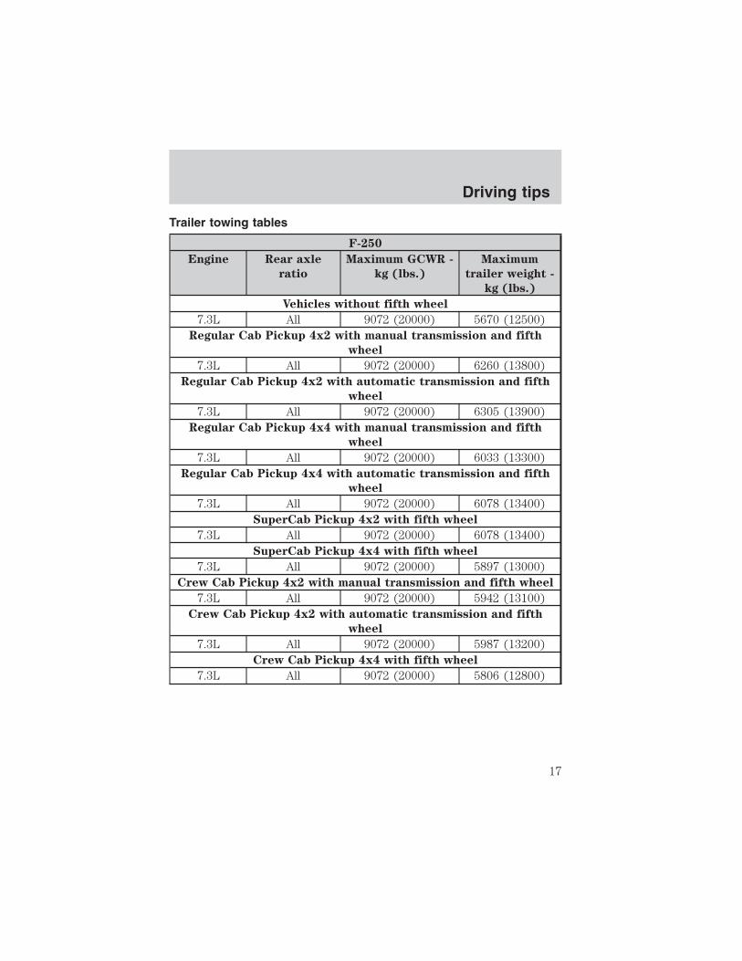
Trailer towing tables
F-250
Engine Rear axle
ratio
Maximum GCWR -
kg (lbs.)
Maximum
trailer weight -
kg (lbs.)
Vehicles without fifth wheel
7.3L All 9072 (20000) 5670 (12500)Regular Cab Pickup 4x2 with manual transmission and fifth
wheel
7.3L All 9072 (20000) 6260 (13800)Regular Cab Pickup 4x2 with automatic transmission and fifth
wheel
7.3L All 9072 (20000) 6305 (13900)Regular Cab Pickup 4x4 with manual transmission and fifth
wheel
7.3L All 9072 (20000) 6033 (13300)Regular Cab Pickup 4x4 with automatic transmission and fifth
wheel
7.3L All 9072 (20000) 6078 (13400)SuperCab Pickup 4x2 with fifth wheel
7.3L All 9072 (20000) 6078 (13400)SuperCab Pickup 4x4 with fifth wheel
7.3L All 9072 (20000) 5897 (13000)Crew Cab Pickup 4x2 with manual transmission and fifth wheel
7.3L All 9072 (20000) 5942 (13100)Crew Cab Pickup 4x2 with automatic transmission and fifth
wheel
7.3L All 9072 (20000) 5987 (13200)Crew Cab Pickup 4x4 with fifth wheel
7.3L All 9072 (20000) 5806 (12800)
Driving tips
17

F-350 Regular Cab Single Rear Wheel Pickup
Fifth
Wheel
Option
Rear axle
ratio
Maximum GCWR -
kg (lbs.)
Maximum
trailer weight -
kg (lbs.)
Vehicles without fifth wheel
7.3L All 9072 (20000) 5670 (12500)4x2 with manual transmission and fifth wheel
7.3L All 9072 (20000) 6214 (13700)4x2 with automatic transmission and fifth wheel
7.3L All 9072 (20000) 6260 (13800)4x4 with manual transmission and fifth wheel
7.3L All 9072 (20000) 6033 (13300)4x4 with automatic transmission and fifth wheel
7.3L All 9072 (20000) 6078 (13400)
F-350 Regular Cab Dual Rear Wheel Pickup
Fifth
Wheel
Option
Rear axle
ratio
Maximum GCWR -
kg (lbs.)
Maximum
trailer weight -
kg (lbs.)
Vehicles without fifth wheel
7.3L All 9072 (20000) 5670 (12500)4x2 with fifth wheel
7.3L All 9072 (20000) 6078 (13400)4x4 with manual transmission and fifth wheel
7.3L All 9072 (20000) 5851 (12900)4x4 with automatic transmission and fifth wheel
7.3L All 9072 (20000) 5897 (13000)
Driving tips
18

F-350 SuperCab Single Rear Wheel Pickup
Fifth
Wheel
Option
Rear axle
ratio
Maximum GCWR -
kg (lbs.)
Maximum
trailer weight -
kg (lbs.)
Vehicles without fifth wheel
7.3L All 9072 (20000) 5670 (12500)4x2 with fifth wheel
7.3L All 9072 (20000) 6078 (13400)4x4 with fifth wheel
7.3L All 9072 (20000) 5897 (13000)
F-350 SuperCab Dual Rear Wheel Pickup
Fifth
Wheel
Option
Rear axle
ratio
Maximum GCWR -
kg (lbs.)
Maximum
trailer weight -
kg (lbs.)
Vehicles without fifth wheel
7.3L All 9072 (20000) 5670 (12500)4x2 with fifth wheel
7.3L All 9072 (20000) 5942 (13100)4x4 with manual transmission and fifth wheel
7.3L All 9072 (20000) 5761 (12700)4x4 with automatic transmission and fifth wheel
7.3L All 9072 (20000) 5806 (12800)
Driving tips
19

F-350 Crew Cab Single Rear Wheel Pickup
Fifth
Wheel
Option
Rear axle
ratio
Maximum GCWR -
kg (lbs.)
Maximum
trailer weight -
kg (lbs.)
Vehicles without fifth wheel
7.3L All 9072 (20000) 5670 (12500)4x2 with manual transmission and fifth wheel
7.3L All 9072 (20000) 5942 (13100)4x2 with automatic transmission and fifth wheel
7.3L All 9072 (20000) 5987 (13200)4x4 with fifth wheel
7.3L All 9072 (20000) 5806 (12800)
F-350 Crew Cab Dual Rear Wheel Pickup
Fifth
Wheel
Option
Rear axle
ratio
Maximum GCWR -
kg (lbs.)
Maximum
trailer weight -
kg (lbs.)
4x2 without fifth wheel
7.3L All 9072 (20000) 5670 (12500)4x2 with manual transmission and fifth wheel
7.3L All 9072 (20000) 5806 (12800)4x2 with automatic transmission and fifth wheel
7.3L All 9072 (20000) 5851 (12900)4x4
7.3L All 9072 (20000) 5625 (12400)
Driving tips
20

F-350 Regular Chassis Cab Single Rear Wheel
(Fifth Wheel Towing)
Fifth
Wheel
Option
Rear axle
ratio
Maximum GCWR -
kg (lbs.)
Maximum
trailer weight -
kg (lbs.)
4x2 with manual transmission
7.3L All 9072 (20000) 5942 (13100)4x2 with automatic transmission
7.3L All 9072 (20000) 5987 (13200)4x4
7.3L All 9072 (20000) 5761 (12700)
F-350 Regular Chassis Cab Dual Rear Wheel
(Fifth Wheel Towing)
Fifth
Wheel
Option
Rear axle
ratio
Maximum GCWR -
kg (lbs.)
Maximum
trailer weight -
kg (lbs.)
4x2
7.3L All 9072 (20000) 5806 (12800)4x4
7.3L All 9072 (20000) 5579 (12300)
F-350 SuperCab Chassis Cab Single Rear Wheel
(Fifth Wheel Towing)
Fifth
Wheel
Option
Rear axle
ratio
Maximum GCWR -
kg (lbs.)
Maximum
trailer weight -
kg (lbs.)
4x2
7.3L All 9072 (20000) 5806 (12800)4x4 with manual transmission
7.3L All 9072 (20000) 5579 (12300)4x4 with automatic transmission
7.3L All 9072 (20000) 5625 (12400)
Driving tips
21

F-350 SuperCab Chassis Cab Single Rear Wheel
(Fifth Wheel Towing)
Fifth
Wheel
Option
Rear axle
ratio
Maximum GCWR -
kg (lbs.)
Maximum
trailer weight -
kg (lbs.)
4x2
7.3L All 9072 (20000) 5625 (12400)4x4
7.3L All 9072 (20000) 5443 (12000)
F-350 Crew Cab Chassis Cab Single Rear Wheel
(Fifth Wheel Towing)
Fifth
Wheel
Option
Rear axle
ratio
Maximum GCWR -
kg (lbs.)
Maximum
trailer weight -
kg (lbs.)
4x2
7.3L All 9072 (20000) 5715 (12600)4x4 with manual transmission
7.3L All 9072 (20000) 5488 (12100)4x4 with automatic transmission
7.3L All 9072 (20000) 5534 (12200)
F-350 Crew Cab Chassis Cab Dual Rear Wheel
(Fifth Wheel Towing)
Fifth
Wheel
Option
Rear axle
ratio
Maximum GCWR -
kg (lbs.)
Maximum
trailer weight -
kg (lbs.)
4x2 with manual transmission
7.3L All 9072 (20000) 5534 (12200)4x2 with automatic transmission
7.3L All 9072 (20000) 5579 (12300)4x4
7.3L All 9072 (20000) 5352 (11800)
Driving tips
22

F-450
Fifth
Wheel
Option
Rear axle
ratio
Maximum GCWR -
kg (lbs.)
Maximum
trailer weight -
kg (lbs.)
Regular Chassis Cab 4x2
7.3L All 11793 (26000) 8210 (18100)Regular Chassis Cab 4x4
7.3L All 11793 (26000) 8074 (17800)SuperCab Chassis Cab 4x2 with manual transmission
7.3L All 11793 (26000) 8029 (17700)SuperCab Chassis Cab 4x2 with automatic transmission
7.3L All 11793 (26000) 8074 (17800)SuperCab Chassis Cab 4x4 with manual transmission
7.3L All 11793 (26000) 7847 (17300)SuperCab Chassis Cab 4x4 with automatic transmission
7.3L All 11793 (26000) 7893 (17400)Crew Cab Chassis Cab 4x2
7.3L All 11793 (26000) 7938 (17500)Crew Cab Chassis Cab 4x4
7.3L All 11793 (26000) 7802 (17200)
Driving tips
23
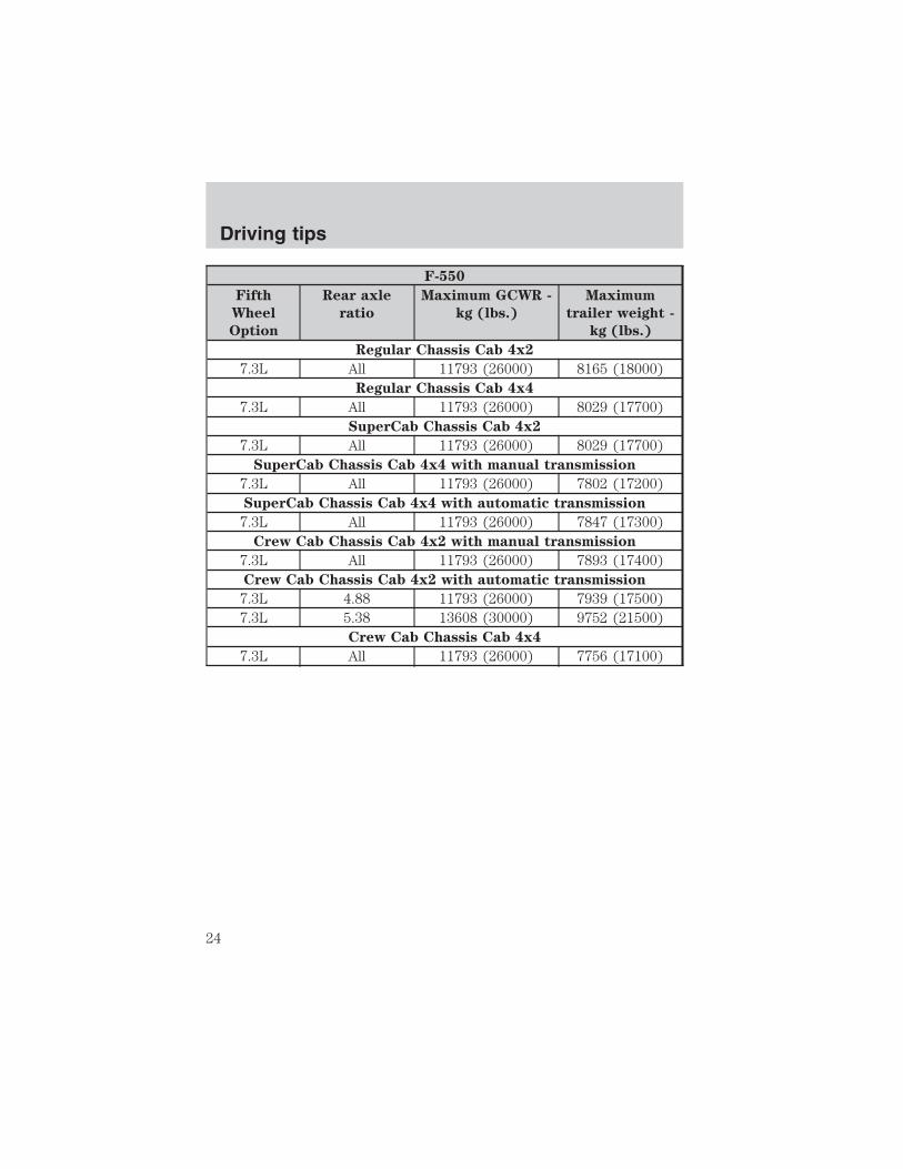
F-550
Fifth
Wheel
Option
Rear axle
ratio
Maximum GCWR -
kg (lbs.)
Maximum
trailer weight -
kg (lbs.)
Regular Chassis Cab 4x2
7.3L All 11793 (26000) 8165 (18000)Regular Chassis Cab 4x4
7.3L All 11793 (26000) 8029 (17700)SuperCab Chassis Cab 4x2
7.3L All 11793 (26000) 8029 (17700)SuperCab Chassis Cab 4x4 with manual transmission
7.3L All 11793 (26000) 7802 (17200)SuperCab Chassis Cab 4x4 with automatic transmission
7.3L All 11793 (26000) 7847 (17300)Crew Cab Chassis Cab 4x2 with manual transmission
7.3L All 11793 (26000) 7893 (17400)Crew Cab Chassis Cab 4x2 with automatic transmission
7.3L 4.88 11793 (26000) 7939 (17500)7.3L 5.38 13608 (30000) 9752 (21500)
Crew Cab Chassis Cab 4x4
7.3L All 11793 (26000) 7756 (17100)
Driving tips
24

SCHEDULED MAINTENANCE
The Scheduled Maintenance Services in the scheduled maintenanceguide are required because they are considered essential to the life andperformance of your vehicle.
Use only recommended fuel, lubricants, fluids and service partsconforming to Ford specifications. Motorcraft parts are designed andbuilt for best performance in your vehicle.
CLEANING THE ENGINE
Engines are more efficient when they are clean because grease and dirtbuildup keep the engine warmer than normal. When washing:
• The engine must be cool to the touch before spraying with water.
• Never spray a hot engine with cold water, as damage to theengine block or engine components may occur.
• Use caution when using a self-serve power washer (1,000 psimaximum pressure) to clean the engine, as the high-pressure fluidcould penetrate the sealed parts and cause damage.
• Never apply anything to any exposed belts in the enginecompartment, including the belt dressing.
For general cleaning of the engine and engine compartment, sprayEngine Shampoo (ZC-20) on all parts that require cleaning and pressurerinse the area with cool water.
Cover the highlighted areas to prevent water damage when cleaning theengine (never wash or rinse the engine while it is running; waterin the running engine may cause internal damage):
General maintenance information
25
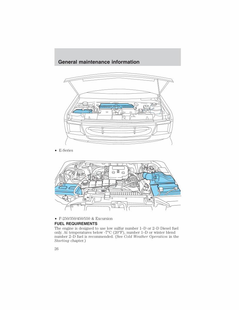
• E-Series
• F-250/350/450/550 & ExcursionFUEL REQUIREMENTSThe engine is designed to use low sulfur number 1–D or 2–D Diesel fuelonly. At temperatures below -7°C (20°F), number 1–D or winter blendnumber 2–D fuel is recommended. (See Cold Weather Operation in theStarting chapter.)
General maintenance information
26

Do not use fuel intended for agricultural use (agricultural fuel is
dyed red), home heating oil or any Diesel fuel not intended for
highway use. Damage to the fuel injection system or engine can
occur if an improper fuel is used.
Do not add gasoline, gasohol or alcohol to Diesel fuel. This practicecreates a serious fire hazard and engine performance problems.
It should not be necessary to add any aftermarket additives to your fueltank if you use a properly formulated Diesel fuel that meets the ASTM D975 industry specification. Aftermarket additives can damage the injectorsystem or engine.
Do not blend used engine oil with Diesel fuel under any circumstances.Blending used oil with the fuel will significantly increase your vehicle’sexhaust emissions and reduce engine life due to increased internal wear.
Do not crank the engine for more than 30 seconds at a time as
damage to the starter motor may result.
If the engine fails to start in 30 seconds, turn the key to the OFFposition and wait 30 seconds before trying again.
Truck stops have pumps and nozzles designed for larger, heavy-dutytrucks. When refueling at truck stops: if the nozzle shuts off repeatedlywhen refueling, wait 5–10 seconds; then use a slower rate of flow (don’tdepress the nozzle trigger as far).
If air is allowed to enter the fuel system (during fuel filter change or ifyou run out of fuel) the engine will purge the trapped air as it runs. Theengine may run rough and produce white smoke while air is in thesystem. This is normal and should correct itself in a short time.
An engine that suddenly becomes noisy or operates poorly after a fuel fillcould be using substandard fuel (i.e., high water content, low cetanerating or gasoline in the fuel). Diesel fuel should be purchased from areputable station which sells a large amount of Diesel fuel.
Care should be taken whenever Diesel fuel is stored. Use only clean,approved containers which will prevent the entry of dirt or water.
Diesel fuel must not be stored in a galvanized container. The fuel willdissolve the zinc in a galvanized container. The zinc will then remain insolution until it is run through the engine where it will be deposited inthe fuel injectors causing expensive-to-repair damage.
General maintenance information
27

CHANGING FUEL FILTER
Removal — F-250/350/450/550 and Excursion1. Remove the engine appearancecover.
2. Remove the fuel filter cap byturning counterclockwise.
3. Remove and discard old fuel filterelement and fuel filter o-ring.
4. Carefully clean the matingsurfaces.
Removal — E-Series
1. Remove the engine appearance cover.
2. Disconnect the battery ground cable, then all electrical connectors,vacuum tubes and fasteners as necessary for removal.
3. Release the four retaining clamps on the air cleaner assembly, then liftthe air cleaner cover and remove the air cleaner(s).
4. Loosen the clamp on the air inlet tube, then disconnect the air inlettube from the resonator.
5. Remove the three bolts on the turbocharger heat shield, then theturbocharger heat shield.
6. Remove the bolt and resonator from the vehicle.
General maintenance information
28

7. Remove the fuel filter cap byturning counterclockwise.
8. Remove and discard old fuel filterelement and fuel filter o-ring.
9. Carefully clean the matingsurfaces.
Installation — F-250/350/450/550 and ExcursionThe engine will not run properly if the fuel filter is not installedin housing.
1. Apply a coating of clean Diesel fuel to the new fuel filter o-ring.
2. Install new fuel filter o-ring onto fuel filter element.
3. Install new fuel filter and o-ring into the fuel filter housing.
4. Tighten cap onto fuel filter housing slowly, allowing fuel to soak intothe fuel filter element. Tighten cap until it contacts the housing.
5. Install engine appearance cover.
After replacing the fuel filter, the engine will purge the trappedair as it runs. The engine may run roughly and smoke until the airis completely eliminated.
Using a fuel which has more than average impurities may requirethe fuel filter to be replaced more frequently than the serviceinterval specifies.
Installation — E-SeriesThe engine will not run properly if the fuel filter is not installedin housing.
General maintenance information
29

1. Apply a coating of clean Diesel fuel to the new fuel filter o-ring.
2. Install new fuel filter o-ring onto fuel filter element.
3. Install new fuel filter and o-ring into the fuel filter housing.
4. Tighten cap onto fuel filter housing slowly, allowing fuel to soak intothe fuel filter element. Tighten cap until it contacts the housing.
5. Install the resonator and resonator bolt.
6. Install the turbocharger heat shield, then the three bolts on theturbocharger heat shield.
7. Connect the air inlet tube to the resonator, then tighten the clamp onthe air inlet tube.
8. Install the air cleaner(s), close the air cleaner cover, then close thefour retaining clamps on the air cleaner assembly.
9. Connect the battery ground cable, then all electrical connectors,vacuum tubes and fasteners as necessary for installation.
10. Install the engine appearance cover.
After replacing the fuel filter, the engine will purge the trappedair as it runs. The engine may run roughly and smoke until the airis completely eliminated.
Using a fuel which has more than average impurities may requirethe fuel filter to be replaced more frequently than the serviceinterval specifies.
ENGINE OIL
Checking engine oil level
Because it is normal to add some oil between oil changes, check yourengine oil level each time you stop for fuel. To check the engine oil levelconsistently and accurately, the following procedure is recommended:
1. Have engine at normal operating temperature (at least into theNORMAL range on the engine coolant temperature gauge).
2. Park the vehicle on a level surface, then turn off the engine and openthe hood.
3. Allow at least 20 minutes after engine shutdown to assure that the oilcontained in the upper parts of the engine has returned to the oil pan.
General maintenance information
30
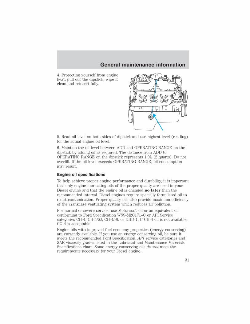
4. Protecting yourself from engineheat, pull out the dipstick, wipe itclean and reinsert fully.
5. Read oil level on both sides of dipstick and use highest level (reading)for the actual engine oil level.
6. Maintain the oil level between ADD and OPERATING RANGE on thedipstick by adding oil as required. The distance from ADD toOPERATING RANGE on the dipstick represents 1.9L (2 quarts). Do notoverfill. If the oil level exceeds OPERATING RANGE, oil consumptionmay result.
Engine oil specifications
To help achieve proper engine performance and durability, it is importantthat only engine lubricating oils of the proper quality are used in yourDiesel engine and that the engine oil is changed no later than therecommended interval. Diesel engines require specially formulated oil toresist contamination. Proper quality oils also provide maximum efficiencyof the crankcase ventilating system which reduces air pollution.
For normal or severe service, use Motorcraft oil or an equivalent oilconforming to Ford Specification WSS-M2C171–C or API Servicecategories CH-4, CH-4/SJ, CH-4/SL or DHD-1. If CH-4 oil is not available,CG-4 is acceptable.
Engine oils with improved fuel economy properties (energy conserving)are currently available. If you use an energy conserving oil, be sure itmeets the recommended Ford Specification, API service categories andSAE viscosity grades listed in the Lubricant and Maintenance MaterialsSpecifications chart. Some energy conserving oils do not meet therequirements necessary for your Diesel engine.
General maintenance information
31
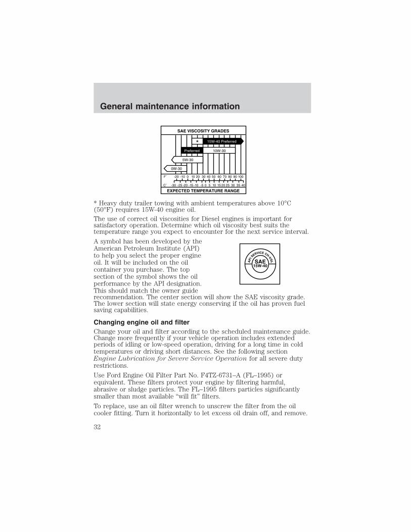
* Heavy duty trailer towing with ambient temperatures above 10°C(50°F) requires 15W-40 engine oil.The use of correct oil viscosities for Diesel engines is important forsatisfactory operation. Determine which oil viscosity best suits thetemperature range you expect to encounter for the next service interval.
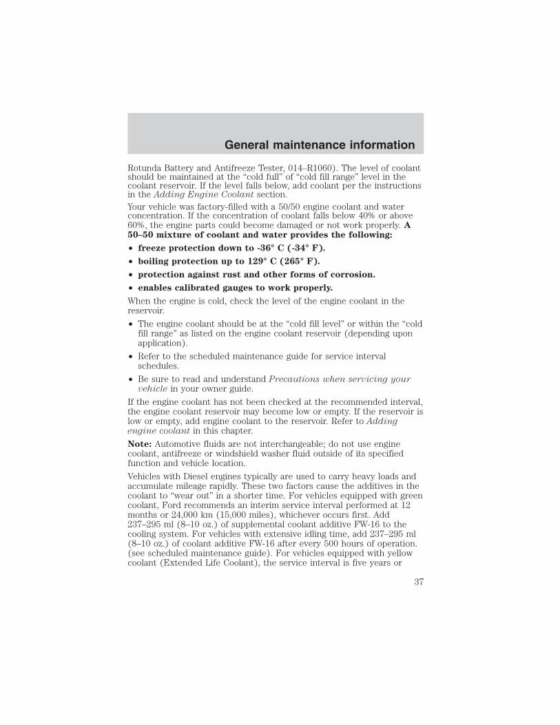
A symbol has been developed by theAmerican Petroleum Institute (API)to help you select the proper engineoil. It will be included on the oilcontainer you purchase. The topsection of the symbol shows the oilperformance by the API designation.This should match the owner guiderecommendation. The center section will show the SAE viscosity grade.The lower section will state energy conserving if the oil has proven fuelsaving capabilities.
Changing engine oil and filterChange your oil and filter according to the scheduled maintenance guide.Change more frequently if your vehicle operation includes extendedperiods of idling or low-speed operation, driving for a long time in coldtemperatures or driving short distances. See the following sectionEngine Lubrication for Severe Service Operation for all severe dutyrestrictions.
Use Ford Engine Oil Filter Part No. F4TZ-6731–A (FL–1995) orequivalent. These filters protect your engine by filtering harmful,abrasive or sludge particles. The FL–1995 filters particles significantlysmaller than most available “will fit” filters.
To replace, use an oil filter wrench to unscrew the filter from the oilcooler fitting. Turn it horizontally to let excess oil drain off, and remove.
AP
I SERVICE CH-4/SLSAE15W-40
General maintenance information
32

Do not handle a hot oil filter with bare hands.
Clean the filter mounting area on the oil cooler, lightly coat the gasketsurface of the new filter with clean engine oil and hand tighten until thegasket contacts the base. Then tighten another 1–1/4 to 2 turns. Fillthe crankcase and run the engine to check for leaks.
Continuous contact with USED motor oil has caused cancer inlaboratory mice. Protect your skin by washing with soap and
water.
Engine lubrication for severe service operationThe following severe service operating conditions require unique enginemaintenance procedures:
• towing a trailer over 1,600 km (1,000 miles)
• sustained, high speed driving at Gross Vehicle Weight Rating(maximum loaded weight for vehicle operation during hotweather-above 32°C [90°F]).
• frequent or extended idling (over 10 minutes per hour of normaldriving).
• operating in severe dust conditions.
• frequent, short trips of 16 km (10 miles) or less during freezingweather
If you are operating your vehicle under any of these conditions, observethe following service procedures:
• Change engine oil and filter every 5,000 km (3,000 miles).
• Use Motorcraft oil or an equivalent oil conforming to FordSpecification WSS-M2C171–C or API categories CH-4, CH-4/SJ,CH-4/SL or DHD-1. If CH-4 oil is not available, CG-4 is acceptable..
For more information refer the Severe Duty Maintenance Schedule inthe “Service Guide”.
REPLACING THE AIR FILTER ELEMENTWhen replacing the air filter element, use the Motorcraft air filterelement listed. Refer to Lubricant and Maintenance MaterialsSpecifications in this supplement.
General maintenance information
33

Failure to use the correct air filter element may result in severe
engine damage.
1. Remove air filter element from the housing, taking care to prevent dirtfrom falling into the engine air intake.
2. Clean the air filter housing and cover to ensure good sealing.
3. Install a new air filter element. Be careful not to crimp the filter edgesbetween the air filter housing and cover. This could cause damage to theair filter element and possible severe damage to the engine.
When servicing the air filter, always be sure that the rubber
water drain hose is not kinked or obstructed. Failure to do so
may result in severe engine damage when driving through deep
water and/or encountering unusually heavy precipitation
conditions.
FUEL FILTER/WATER SEPARATOR
The engine is equipped with a combination fuel filter/water separatorlocated in the “V” of the engine.
• E-Series
• F-250/350/450/550, Excursion
Water should be drained from thefilter bowl whenever the warninglight comes on or every 8 000 km(5 000 miles). The WATER IN FUEL light will come on whenapproximately 100 cc (0.2 pints) of water accumulates in the separator.
Replace the fuel filter with Motorcraft Part No. FD-4596 (Ford Part No.F81Z-9N184–AA).
Fuel filter/water separator drain procedure1. Stop the vehicle and shut off the engine.
The vehicle must be stopped with the engine off when drainingthe fuel filter/water separator. Fuel may ignite if separator is
drained while the engine is running or vehicle is moving.
General maintenance information
34

2. Open the hood. Place anappropriate container under thefilter drain under the vehicle.
3. Locate the fuel filter drain valve. If necessary, remove the engineappearance cover. Refer to Engine Compartment in the Service pointschapter.
4. On F-Series and Excursionmodels, open fuel filter drain valveby turning clockwise. Allow to drainfor approximately 25 seconds oruntil clean fuel is observed. Closefilter drain valve by turningcounterclockwise until firmly seated.
DR
AIN
CLOSE
General maintenance information
35

4. On E-Series models, open fuel filter drain valve by pulling on therelease handle. Allow to drain for approximately 25 seconds or untilclean fuel is observed. Close filter drain valve by resetting handle tooriginal position.
5. Verify that the fuel filter drain valve is closed. If removed, install theengine appearance cover.
6. Close the hood and remove the container from under the vehicle.
7. Restart the engine and check WATER IN FUEL indicator light. Thelight should not glow. If it continues to glow, have fuel system checkedand repaired.
ENGINE COOLANT
Checking engine coolantThe concentration and level of engine coolant should be checked at themileage intervals listed in the scheduled maintenance guide. The coolantconcentration should be maintained at 50/50 coolant and water, whichequates to a freeze point of -36° C (-34° F). Coolant concentrationtesting is possible with a hydrometer or antifreeze tester (such as the
General maintenance information
36
Rotunda Battery and Antifreeze Tester, 014–R1060). The level of coolantshould be maintained at the “cold full” of “cold fill range” level in thecoolant reservoir. If the level falls below, add coolant per the instructionsin the Adding Engine Coolant section.Your vehicle was factory-filled with a 50/50 engine coolant and waterconcentration. If the concentration of coolant falls below 40% or above60%, the engine parts could become damaged or not work properly. A50–50 mixture of coolant and water provides the following:
• freeze protection down to -36° C (-34° F).
• boiling protection up to 129° C (265° F).
• protection against rust and other forms of corrosion.
• enables calibrated gauges to work properly.
When the engine is cold, check the level of the engine coolant in thereservoir.
• The engine coolant should be at the “cold fill level” or within the “coldfill range” as listed on the engine coolant reservoir (depending uponapplication).
• Refer to the scheduled maintenance guide for service intervalschedules.
• Be sure to read and understand Precautions when servicing yourvehicle in your owner guide.
If the engine coolant has not been checked at the recommended interval,the engine coolant reservoir may become low or empty. If the reservoir islow or empty, add engine coolant to the reservoir. Refer to Addingengine coolant in this chapter.
Note: Automotive fluids are not interchangeable; do not use enginecoolant, antifreeze or windshield washer fluid outside of its specifiedfunction and vehicle location.
Vehicles with Diesel engines typically are used to carry heavy loads andaccumulate mileage rapidly. These two factors cause the additives in thecoolant to “wear out” in a shorter time. For vehicles equipped with greencoolant, Ford recommends an interim service interval performed at 12months or 24,000 km (15,000 miles), whichever occurs first. Add237–295 ml (8–10 oz.) of supplemental coolant additive FW-16 to thecooling system. For vehicles with extensive idling time, add 237–295 ml(8–10 oz.) of coolant additive FW-16 after every 500 hours of operation.(see scheduled maintenance guide). For vehicles equipped with yellowcoolant (Extended Life Coolant), the service interval is five years or
General maintenance information
37

100,000 miles and three years or 50,000 miles thereafter. Vehiclesequipped with the Extended Life Coolant do not require any additives.
Adding engine coolant
When adding coolant, make sure it is a 50/50 mixture of engine coolantand distilled water. Add the mixture to the coolant reservoir, when the
engine is cool, until the appropriate fill level is obtained.
Do not add engine coolant when the engine is hot. Steam andscalding liquids released from a hot cooling system can burn you
badly. Also, you can be burned if you spill coolant on hot engine parts.
Do not put engine coolant in the windshield washer fluidcontainer. If sprayed on the windshield, engine coolant could
make it difficult to see through the windshield.
The cooling system in your vehicle is filled with either green-coloredMotorcraft Premium Engine Coolant meeting Ford specificationESE-M97B44–A or yellow-colored Motorcraft Premium Gold EngineCoolant meeting Ford Specification WSS-M97B51–A1. To determine yourvehicle’s coolant type (color), check your coolant reservoir.
• Add Motorcraft Premium Engine Coolant (green-colored),VC-4–A (U.S.) or CXC-10 (Canada) or Motorcraft PremiumGold Engine Coolant (yellow-colored), VC-7–A, depending onthe type of coolant originally equipped in your vehicle. If youare unsure which type of coolant your vehicle requires, check yourcoolant reservoir or contact your local dealer.
• Do not add/mix an orange-colored, extended life coolant suchas Motorcraft Speciality Orange Engine Coolant, VC-2 (US) orCXC-209 (Canada), meeting Ford specification WSS-M97B44–Dwith the factory-filled coolant. Mixing Motorcraft Speciality OrangeEngine Coolant or any orange-colored extended life product with yourfactory filled coolant can result in degraded corrosion protection.
• A large amount of water without engine coolant may be added, in caseof emergency, to reach a vehicle service location. In this instance, thecooling system must be drained and refilled with a 50/50 mixture ofengine coolant and distilled water as soon as possible. Water alone(without engine coolant) can cause engine damage from corrosion,overheating or freezing.
General maintenance information
38

• Do not use alcohol, methanol or brine or any engine coolantsmixed with alcohol or methanol antifreeze (coolant). Alcoholand other liquids can cause engine damage from overheating orfreezing.
• Do not add extra inhibitors or additives to the coolant. Thesecan be harmful and compromise the corrosion protection of the enginecoolant.
• Do not mix with recycled coolant unless from a Ford-approvedrecycling process (see Use of Recycled Engine Coolant section).
For vehicles with overflow coolant systems with a non-pressurized capon the coolant recovery system, add coolant to the coolant recoveryreservoir when the engine is cool. Add the proper mixture of coolant andwater to the “cold full” level. For all other vehicles, which have a coolantdegas system with a pressurized cap, or if it is necessary to remove thecoolant pressure relief cap on the radiator of a vehicle with an overflowsystem, follow these steps to add engine coolant.
To reduce the risk of personal injury, make sure the engine iscool before unscrewing the coolant pressure relief cap. The
cooling system is under pressure; steam and hot liquid can come outforcefully when the cap is loosened slightly.
1. Before you begin, turn the engine off and let it cool.
2. When the engine is cool, wrap a thick cloth around the coolantpressure relief cap on the coolant reservoir (an semi-clear plastic bottle).Slowly turn cap counterclockwise (left) until pressure begins to release.
3. Step back while the pressure releases.
4. When you are sure that all the pressure has been released, use thecloth to turn it counterclockwise and remove the cap.
5. Fill the coolant reservoir slowly with the proper coolant mixture (seeabove), to within the “cold fill range” or the “cold full” level on thereservoir. If you removed the radiator cap in an overflow system, fill theradiator until the coolant is visible and radiator is almost full.
6. Replace the cap. Turn until tightly installed. (Cap must be tightlyinstalled to prevent coolant loss.)
After any coolant has been added, check the coolant concentration seeChecking Engine Coolant section). If the concentration is not 50/50(protection to –34°F/–36°C), drain some coolant and adjust theconcentration. It may take several drains and additions to obtain a 50/50coolant concentration.
General maintenance information
39

Whenever coolant has been added, the coolant level in the coolantreservoir should be checked the next few times you drive the vehicle. Ifnecessary, add enough 50/50 concentration of engine coolant anddistilled water to bring the liquid level to the proper level.
If you have to add more than 1.0 liter (1.0 quart) of engine coolant permonth, have your dealer check the engine cooling system. Your coolingsystem may have a leak. Operating an engine with a low level of coolantcan result in engine overheating and possible engine damage.
Replacing coolantA coolant mixture of 50% coolant concentrate and 50% water isrecommended to maintain best overall performance. To avoid damagingthe engine and radiator, the coolant concentrate should not exceed 60%.When refilling the coolant system either as part of the regularmaintenance (refer to the scheduled maintenance guide), or due toservice performed, adhere to the following instructions:
1. Drain and flush the cooling system to remove dirt deposits, oil, rustparticles.
Note: When filling the system with Motorcraft Premium Engine Coolant(green-colored) or equivalent meeting Ford specificationESE-M97B44–A, a supplemental coolant additive is required. Refer toAdding Coolant section to determine the coolant type in your vehicle.Add 1.89L (4 pints) of Motorcraft Heavy Duty Cooling System AdditiveFW-16 or equivalent meeting Ford specification ESN-M99B169–A,directly to the cooling system. An additional 237–295 ml (8–10 oz.) ofsupplemental coolant additive FW-16 should be added at 24,000 km(15,000 mile) intervals to maintain proper concentration. Do not usethis additive with yellow-colored coolant meeting Fordspecification WSS-M97B51–A1.
2. Fill the coolant reservoir with the specified coolant/water mixture untilthe level stabilizes at the top hose fitting. Replace and tighten cap. Fillthe coolant bottle to the cold fill mark.
3. Reinstall the coolant bottle cap.
4. Start and idle engine until the radiator upper hose is warm(approximately 10–15 minutes). If the hose does not get warm thenrepeat at a higher engine speed.
5. Immediately shut off engine. Allow engine to cool before removingcoolant bottle cap. Cautiously remove coolant bottle cap and add coolantto Cold Fill mark.
General maintenance information
40

Recycled engine coolantFord Motor Company recommends the use of a recycled engine coolantproduced by Ford-approved processes in vehicles originally equippedwith Motorcraft Premium Engine Coolant (green-colored). However, notall coolant recycling processes produce coolant that meets Fordspecification ESE-M97B44–A. Use of such coolant may harm the engineand cooling system components.Ford Motor Company does NOT recommend the use of recycled enginecoolant in vehicles originally equipped with Motorcraft Premium GoldEngine Coolant since a Ford-approved recycling process is not yetavailable.
Used engine coolant should be disposed of in an appropriatemanner. Follow your community’s regulations and standards for recyclingand disposing of automotive fluids.
Coolant refill capacityTo find out how much fluid your vehicle’s cooling system can hold, referto Refill capacities in this chapter.Fill your engine coolant reservoir as outlined in Adding engine coolant.
Severe climatesIf you drive in extremely cold climates (less than –36° C [–34° F]):• it may be necessary to increase the coolant concentration
above 50%.
• NEVER increase the coolant concentration above 60%.
• increased engine coolant concentrations above 60% willdecrease the overheat protection characteristics of the enginecoolant and may cause engine damage.
• refer to the chart on the coolant container to ensure thecoolant concentration in your vehicle will provide adequatefreeze protection at the temperatures in which you drive in thewinter months.
If you drive in extremely hot climates:
• it is still necessary to maintain the coolant concentrationabove 40%.
• NEVER decrease the coolant concentration below 40%.
• decreased engine coolant concentrations below 40% willdecrease the corrosion protection characteristics of the enginecoolant and may cause engine damage.
General maintenance information
41
• decreased engine coolant concentrations below 40% willdecrease the freeze protection characteristics of the enginecoolant and may cause engine damage.
• refer to the chart on the coolant container to ensure thecoolant concentration in your vehicle will provide adequateprotection at the temperatures in which you drive.
Vehicles driven year-round in non-extreme climates should use a 50/50mixture of engine coolant and distilled water for optimum cooling systemand engine protection.
Coolant conditioner (liquid)For engines filled with green-colored Motorcraft Premium EngineCoolant, a supplemental coolant additive FW-16 meeting Fordspecification ESN-M99B169–A has been added to the coolant in thisengine.
This additive aids in the prevention of rust and scale buildup on theinternal parts of the cooling system. Prevention of rust and scale buildupallows for proper dissipation of heat generated by combustion.
See the scheduled maintenance guide for recommended intervals.
EMISSION CONTROL SYSTEM(S) LAWSFederal law prohibits vehicle manufacturers, dealers and other personsengaged in the business of repairing, servicing, selling, leasing or tradingmotor vehicles as well as fleet operations from unknowingly removing orrendering emission control system(s) inoperative. Further, modificationsof the emission control system(s) could create liability on the part of theindividual owners under the laws of some states. In Canada,modifications of the emission control system(s) could create liabilityunder applicable Federal or Provincial laws.
Do not remove or alter the original equipment floor covering orinsulation between it and the metal floor of the vehicle. The floorcovering and insulation protect occupants of the vehicle from the engineand exhaust system heat and noise. On vehicles with no originalequipment floor covering insulation, do not carry passengers in a mannerthat permits prolonged skin contact with the metal floor. Provideadequate insulation.
General maintenance information
42

NOISE EMISSIONS WARRANTY, PROHIBITED TAMPERING ACTSAND MAINTENANCEOn January 1, 1978, Federal regulation became effective governing thenoise emission on trucks over 4,536 kg (10,000 lbs.) GVWR (GrossVehicle Weight Rating). The following statements concerning prohibitedtampering acts and maintenance, and the noise warranty found in theWarranty Facts Booklet, are applicable to complete chassis cabs over4,536 (10,000 lbs.) GVWR.
Tampering with noise control system prohibitedFederal law prohibits the following acts or the causing thereof: (1) Theremoval or rendering inoperative by any person other than for purposesof maintenance, repair or replacement of any device or element of designincorporated into any new vehicle for the purpose of noise control priorto its sale or delivery to the ultimate purchaser or while it is in use, or(2) the use of the vehicle after such device or element of design hasbeen removed or rendered inoperative by any person.
Among those acts which the U.S. Environmental Protection Agency maypresume to constitute tampering are the acts listed below:
• Removal of hood blanket, fender apron absorbers, fender apronbarriers, underbody noise shields or acoustically absorptive material.
• Tampering or rendering inoperative the engine speed governor, so asto allow engine speed to exceed manufacturer’s specifications.
General maintenance information
43

VEHICLE EMISSIONS CONTROL INFORMATION (VECI)Emissions information appears onthe VECI decal on the engine valvecover. This decal identifies enginedisplacement and provides certainengine specifications.
SCHEDULED MAINTENANCE SERVICESRefer to your scheduled maintenance guide for details of maintenance onyour vehicle.
If you are using your vehicle in a manner in which it will remainstationary (door to door service, taxi, etc.), then it is recommended thatyou change the engine oil every 200 engine hours as opposed to amileage limit. Since most vehicles are not equipped with hourmeters, itmay be necessary for you to approximate your time and plan engine oiland filter changes accordingly.
Any modification of the emissions control system could create liabilityunder federal law (U.S.) if made prior to sale and registration, under thelaws of some states if made thereafter. Further, federal law prohibitsvehicle manufacturers, dealers and other persons engaged in thebusiness of repairing, servicing, selling, leasing or trading motor vehiclesas well as fleet operations from knowingly removing or rendering anemissions control system inoperative after sale and delivery to anultimate purchaser. In Canada, modifications of the emissions controlsystem could create liability under applicable federal or provincial laws.
Scheduled maintenance
44

The complexity of the Diesel engine makes it so the owner isdiscouraged from attempting to perform maintenance other than theservices described in this supplement.
If you experience difficult starting, rough idling, excessive exhaustsmoke, a decrease in engine performance or excess fuel consumption,perform the following checks:
• a plugged air inlet system or engine air filter element.
• water in the fuel filter/water separator.
• a clogged fuel filter.
• contaminated fuel.
• air in the fuel system, due to loose connections.
• an open or pinched sensor hose.
• low engine oil level.
• wrong fuel for climactic conditions.
If these checks do not help you correct the engine performance problemyou are experiencing, consult an authorized dealer.
FUELING
Do not use starting fluid such as ether or gasoline in the Dieselair intake system. Such fluids can cause immediate explosive
damage to the engine and possible personal injury.
If you fuel your vehicle at a truck stop, you may notice that the fuelnozzle may shut off every 5–10 seconds. This is due to the flow ratesbeing designed for larger heavy duty trucks. You may have to fuel at aslower rate (don’t depress the nozzle trigger fully).
Do not run your Diesel vehicle out of fuel as this will allow air to enterthe fuel system which will make restarting difficult. Longer enginecranking time may be required once air is in the fuel system. If air entersthe fuel system (either through running the fuel tank(s) empty or duringa fuel filter change), the engine will self-purge the trapped air once itstarts running. The engine may run roughly and produce white smokewhile air is in the fuel system; this is normal and should stop after ashort time.
Minor troubleshooting guide
45

IF THE ENGINE WON’T CRANKTurn on the headlights. If the lights are dim, do not go on at all or ifwhen the ignition is turned to START the lights become dim or go out,the battery connections may be loose or corroded, or the battery may bedischarged. If there is a clicking or stuttering sound coming from theengine compartment when you turn the key to START, this may alsoindicate a loose or corroded battery connection.
Check the battery connections at the battery posts, cable connection tothe engine grounding point and at the starter relay terminals. Also, makesure the relay bracket is securely fastened to its mounting surface.
If the starter relay clicks, but the starter does not crank, check theconnections at the starter terminal. If a discharged battery is suspected,have it checked and corrected.
• For vehicles with manual transmissions, the clutch pedal must be fullydepressed in order for the starter to operate.
• For vehicles with automatic transmissions, the gearshift lever must bein Park or Neutral in order for the starter to operate.
• Try operating the starter switch several times. Should the switch becorroded, this operation may clean the contacts or make the switchtemporarily operable until you can reach the dealer.
• If all electrical connections are tight and you need assistance to start,see “Jump Starting Your Vehicle”.
IF ENGINE CRANKS BUT WON’T STARTProlonged starter cranking (in excess of 30 seconds) could causedamage to the starter motor.
• Check the fuel gauge. You may be out of fuel. If the gauge shows thatthere is fuel in the tank, the trouble may be in the electrical system orthe fuel system. If equipped with an auxiliary tank, be sure that thetank control switch is set for the tank with fuel and not on an emptytank.
• Leaving the ignition key ON for over two minutes without starting maymake starting difficult because the glow plugs will cease activation.Reset the system by turning the ignition key to OFF and then back toON again.
Minor troubleshooting guide
46

IF THE ENGINE RUNS HOTThe following could cause the engine to overheat:
• Lack of coolant.
• Dirty cooling system.
• Plugged radiator fins, charge air cooler, A/C condenser and/or oilcooler.
• Driving with frozen coolant.
• Sticking thermostat.
• Overloading or pulling heavy trailers during hot weather.
• Grill or radiator air blockage.
• Slipping or missing drive belt.
• Plugged or very dirty air cleaner element.
IF FUSES BURN OUTBurned-out or blown fuses usually indicate an electrical short-circuit,although a fuse may occasionally burn out from vibration. Insert a secondfuse. If this fuse immediately burns out and you cannot locate the cause,return your vehicle to your dealer for a circuit check.
Replacement fuses and circuit breakers must always be the samerating as the original equipment shown. Never replace a fuse or
circuit breaker with one of a higher rating. Higher rated fuses or circuitbreakers could allow circuit overloading in the event of a circuitmalfunction, resulting in severe vehicle damage or personal injury.
Refer to the “Owner Guide” for replacement of fuses.
Minor troubleshooting guide
47

REFILL CAPACITIES
Component Capacity
Cooling system (E-Series) 1, 2, 3 28.5L (30.0 quarts)Cooling system (F-Series and Excursion) 1, 3 31.0L (32.75 quarts)Engine oil 4 14.2 L (15.0 quarts)Fuel tank (F-Series) Refer to Owner GuideFuel tank (Excursion) 166.6L (44.0 gallons)Fuel tank (E-Series) 5 132.5L (35.0 gallons)Radiator cap 90 kPa (13 psi)Manual transmission 6 5.5L (5.8 quarts)Automatic transmission Refer to Owner Guide
1Includes heater and 4.7L (5 quarts) in coolant recovery.2Add 2.5L (2.6 quarts) if equipped with auxiliary heater option.3Add the coolant type originally equipped in your vehicle. For vehiclesfilled with Motorcraft Premium Engine Coolant (green-colored) add1.89L (4 pints) of supplemental coolant additive, FW-16 or equivalent,meeting Ford Specification ESN-M99B169–A.4Includes 1.9L (2 quarts) in engine oil filter.5Optional DRW cutaway and all standard E-450 models are 208.2L (55.0gallons).6Use Motorcraft MERCON� ATF, Motorcraft part number XT-2–QDX,meeting Ford specification MERCON�.
BULB SPECIFICATIONS
Lamp descriptionNumber of bulbs
required
Trade number
Wait to Start Light 1 194Water-in-Fuel Light 1 194Engine Temp. Light 1 194
Capacities and specifications
48

LUBRICANT AND MAINTENANCE MATERIALS SPECIFICATIONS
ItemFord Part
NameFord PartNumber
Ford Specification
Engine Oil
MotorcraftMotor Oil
15W40 SuperDuty, 10W30Super Duty
XO-15W40-QSD,XO-10W30-QSD
WSS-M2C171-C,CH-4/SJ/SL, DHD-1
Engine OilFilter (Use this
filter Only)- F4TZ-6731-A
(FL-1995) -
Air Filter(F-Series andExcursion) 1
- FA-1680 ES-E95AE-9601-AA
Air Filter(E-Series)
(2 Required)- FA-1618 ES-E95AE-9601-AA
Battery(2 Required) - BXT-65-750 -
EngineCoolant2
MotorcraftPremium
Engine Coolant(green-colored)
VC-4–A (US)or CXC-10(Canada)
ESE-M97B44–A
MotorcraftPremium GoldEngine Coolant
(yellow-colored)
VC-7–A WSS-M97B51–A1
Engine CoolantAdditive3
MotorcraftHeavy Duty
Cooling SystemAdditive
FW-16 ESN-M99B169–A
ManualTransmission
MotorcraftMERCON� ATF XT-2–QDX MERCON�
1Always use the authorized Motorcraft air filter listed.
Failure to use the correct air filter may result in severe enginedamage.2Add the engine coolant type originally equipped with your vehicle.3Use only when filling with Motorcraft Premium Engine Coolant(green-colored).
Capacities and specifications
49

E-SERIES ENGINE COMPARTMENT
1. Battery
2. Windshield washer fluid reservoir
3. Engine oil dipstick
4. Fuel filter/water separator drain valve release handle
5. Automatic transmission fluid dipstick
6. Air filter assembly
7. Engine oil filler
8. Air filter restriction gauge
9. Power steering fluid reservoir
10. Brake fluid reservoir
11. Engine coolant recovery reservoir
1
2 3 4 5 6 7 8 9 10
11
Service points
50

F-SERIES AND EXCURSION ENGINE COMPARTMENT
1. Battery (dual batteries shown)
2. Engine coolant recovery reservoir
3. Engine oil filler
4. Engine oil dipstick
5. Automatic transmission dipstick (if equipped)
6. Fuel filter drain valve
7. Clutch fluid reservoir (if equipped)
8. Brake fluid reservoir
9. Air filter restriction gauge
10. Air filter assembly
11. Power steering fluid reservoir
12. Windshield washer fluid reservoir
Service points
51

52

53

54

55

56