table of contents dodge torque-arm ii
TRANSCRIPT

G2-1 D O D G E ® TO RQ U E - A R M A N D MTA I I G E A R I N G EN G I N EER I N G C ATA LO G
Table o
f Co
ntents &R
eference Guid
eTo
rque-A
rm II
Mo
torized To
rque-A
rm II
Torq
ue-Arm
Eng
ineeringB
ulk Material H
andling
Part Num
ber Ind
ex
G2-3 Features and benefits
G2-7 Specifications
G2-8 Nomenclature
G2-9 Easy selection
G2-12 Selection
G2-14 Application classification and class numbers
G2-15 Class I selections
G2-20 Class II selections
G2-25 Class III selections
G2-29 Selection guide
G2-30 Selection and dimensions
G2-30 TA0107L
G2-38 TA1107H
G2-46 TA2115H
G2-54 TA3203H
G2-62 TA4207H
G2-70 TA5215H
G2-78 TA6307H
Selection and dimensions (continued)
G2-86 TA7315H
G2-94 TA8407H
G2-100 TA9415H
G2-104 TA10507H
G2-108 TA12608H
G2-116 Cooling fan dimensions – TA4207H – TA12608H
G2-117 Related products
G2-117 Harsh duty accessories
G2-119 Maximum bore straight bore TAII reducers
G2-120 Nominal sheave ratios
G2-122 Nominal sheave speeds
G2-123 Renewal parts
G2-125 Engineering and technical
G2-125 NEMA motor and Torque-Arm II reducer information,
backstop lift-off speed
G2-126 Maximum input and output speeds
G2-127 Thrust capacity for screw conveyor drives
G2-128 Lubrication of Torque-Arm II reducers
G2-133 Viscosity classification equivalents
G2-134 Bearing L-10 Life as a function of service factor
— Table of contentsDodge® Torque-Arm II
Torque-Arm II

Part
Num
ber
Ind
exEn
gin
eeri
ngB
ulk
Mat
eria
l Han
dlin
gTo
rque
-Arm
To
rque
-Arm
IIM
oto
rize
d To
rque
-Arm
IITa
ble
of
Co
nten
ts &
Ref
eren
ce G
uid
e
TO R Q U E- A R M I I G2-2
— Torque-Arm II shaft mount speed reducersFeatures and benefits
Features and benefits
Since 1949, Dodge® Torque-Arm products have provendependability with more than 2 million units in servicethroughout the world. Dodge Torque-Arm speedreducers are the standard of the industry. Now, thatlegacy continues with the latest generation in shaftmounted speed reducers – Torque-Arm II – offeringpatented innovations, heavy duty features, plus classleading torque and horsepower ratings.

Table o
f Co
ntents &R
eference Guid
eTo
rque-A
rm II
Mo
torized To
rque-A
rm II
Torq
ue-Arm
Eng
ineeringB
ulk Material H
andling
Part Num
ber Ind
ex
G2-3 D O D G E ® TO RQ U E - A R M A N D MTA I I G E A R I N G EN G I N EER I N G C ATA LO G
The Dodge Torque-Arm II surpasses all other reducers on the market because of its
industry proven design and patented features.
This powerful line of shaft mounted speed reducers - in 12 case sizes through 700 (Hp) – offers unparalleled torque ratings and is quickly becoming the new industry standard.
Improved features and capabilities include:
• Twelve reducer sizes with modular accessories
• Meets or exceeds AGMA design standards including 5,000 hour L-10 bearing life, 25,000 average life
• Conformance to ATEX directive 94//9/EC guidelines
• The only backstop that works with EP additives
• Patented harsh duty sealing system with filter breather
• Single steel motor mount that works for all positions and motor heights
• 40:1 ratio added to expand standard product offering of 5, 9, 15, and 25:1
• Patented twin tapered bushing systems to accommodate shafts from 1 inch through 7 inches
• Complete Metric TA II product line available with metric reducers and bushings
• All reducers can be shaft mounted, screw conveyor, vertical and flange mounted
The class leading ratings of the Torque-Arm II line are the result of the extended gear
centers, larger diameter gears, and optimized gear tooth geometry. The backstop design features centrifugal lift-off sprags for extended life and can be used with lubricantscontaining EP additives.
In addition, the Torque-Arm II line has a patented, harsh duty, premium sealing system that uses a harsh duty oil seal protected by a metal excluder seal with rubbing lip. A perfect fit for today’s harsh duty industries such as aggregates, mining, cement, asphalt, mixing & milling, grain, and ethanol.
The steel motor mount adjusts to multiple center distances and mounts in shaft mount and screw conveyor positions.
Its patented twin tapered bushing system - in standard length, short shaft, and metric versions - offers all the features of our standard twin tapered Torque-Arm bushing design which are unique to Dodge, while allowing the replacement of straight bore or single bushed reducers.
Features and BenefitsTorque-Arm II shaft mount speed reducers
Shaft mounted reducer with twin tapered
Screw conveyor drive with adapter, drive

Part
Num
ber
Ind
exEn
gin
eeri
ngB
ulk
Mat
eria
l Han
dlin
gTo
rque
-Arm
To
rque
-Arm
IIM
oto
rize
d To
rque
-Arm
IITa
ble
of
Co
nten
ts &
Ref
eren
ce G
uid
e
TO R Q U E- A R M I I G2-4
Rugged heavy duty design
Engineered for extended operating life
• AGMA standard design providing minimum average bearing life (L50) of 25,000 hours at 1.0 service factor
• Manufactured with heavy duty tapered roller bearings to withstand heavy shock loads
• Heavy duty gearing ensures high efficiency and 200% overload starting capacity at 1.0 service factor
Harsh duty seals to withstand any environment
• Dual sealing systems on all shafts consist of metal reinforced oil seals that are protected by an external metal shield and excluder lip
• Oil seals have an operating temperature range of -40°F to 300°F / -40°C to 150°C
• Compatible with both mineral and synthetic lubricants
• Easy to install, optional v-ring seals available for severe applications
Engineered for extended operating life
• Manufactured with tapered roller bearings to withstand high shock loads
• Designed to exceed AGMA standards, the Torque-Arm II has twice the bearing life compared to most competitors
• 200% overload starting capacity ensures high efficiency and reliability
Dodge twin tapered bushings for easy installation and removal
• System features two fully split, ductile iron, 8° taper bushings that provide sturdy concentric grip on the shaft
• Eliminates fretting corrosion, which can cause difficult removal
• No special tools required for installation or removal
• Full length key ensures maximum torque transmission
• Available in standard and short shaft designs to allow for easy replacement of straight bore and single bushed reducers
Features and BenefitsTorque-Arm II shaft mount speed reducers

Table o
f Co
ntents &R
eference Guid
eTo
rque-A
rm II
Mo
torized To
rque-A
rm II
Torq
ue-Arm
Eng
ineeringB
ulk Material H
andling
Part Num
ber Ind
ex
G2-5 D O D G E ® TO RQ U E - A R M A N D MTA I I G E A R I N G EN G I N EER I N G C ATA LO G
Belt guard package
Allows for multiple height adjustments, featuring a lift-off cover construction. Optional - New full featured Position B-M2 belt guards offer enhanced safety and maintenance features.
Motor mount
Provides stable mounting between motor and reducer to minimize overhung load and withstand heavy shock loading.
Hydra-lock breather
To be used in humid or dusty environments, this optional breather’s check valve system prevents ambient conditions and improves positive maintenance practices.
Twin tapered bushing
Easy on, easy off assembly providing reliable support on both sides of reducer. Available for shorter shafts when replacing a single bushed or straight bore reducer.
Backstop
Safety feature that prevents reverse rotation when system stops. Compatible with standard and EP lubricants without requiring external lubrication.
Tie rod kit
Provides a safety link between reducer and structure to prevent system rotation. Standard rods and turnbuckles are now zinc coated for corrosion resistance.
Bushing covers
Reducers are pre-drilled and tapped to accept Dodge ABS polymer covers. Solid and pre-split versions available to accommodate both sides of reducers.
Features and BenefitsShaft mount speed reducer accessories

Part
Num
ber
Ind
exEn
gin
eeri
ngB
ulk
Mat
eria
l Han
dlin
gTo
rque
-Arm
To
rque
-Arm
IIM
oto
rize
d To
rque
-Arm
IITa
ble
of
Co
nten
ts &
Ref
eren
ce G
uid
e
TO R Q U E- A R M I I G2-6
Belt guard package
Allows for multiple height adjustments, featuring a lift-off cover construction.
Motor mount
Provides stable mounting between motor and reducer to minimize overhung load and withstand heavy shock loading.
Hydra-lock breather
To be used in humid or dusty environments, this optional breathers check valve system prevents ambient conditions and improves positive maintenance practices.
Adjustable packing kit
Additional kit to bolt on the CEMA adapter in hostile environments. Packing can be retightened & replaced to extend life.
CEMA adapter
Featuring double lip seals on both surfaces. The adapter extends operating life and provides stable mounting to screw conveyor.
CEMA driveshafts
Standard 3-hole screw conveyor drive shafts are the standard for higher torque applications.
Features and BenefitsScrew conveyor speed reducer accessories

Table o
f Co
ntents &R
eference Guid
eTo
rque-A
rm II
Mo
torized To
rque-A
rm II
Torq
ue-Arm
Eng
ineeringB
ulk Material H
andling
Part Num
ber Ind
ex
G2-7 D O D G E ® TO RQ U E - A R M A N D MTA I I G E A R I N G EN G I N EER I N G C ATA LO G
Torque-Arm II speed reducers
The speed reducer shall be either a belt driven or direct coupled enclosed shaft mount type unit with a single or double reduction ratio. The reducer shall mount directly on the driven shaft and utilize an adjustable torque arm that attaches from the gear case to the support structure or foundation. Optional all steel motor mount adjusts to various belt center distances and supports the motor.
The reducer housing shall be constructed of two piece corrosion resistant, class 30 gray iron. All housings shall be doweled and precision machined to assure accurate alignment for all gear sets. Pry slots are provided for ease of repair.
All gearing shall be of helical design, case carburized and precision finished to insure a high surface durability with a resilient tooth core for impact resistance and optimum service life. Gears shall be supported between bearings to maintain proper alignment of gear meshes, maximize load carrying capabilities, and to eliminate overhung loads imposed on bearings. Design meets or exceed AGMA standards. Reducer bearings shall be of the tapered roller type, meet or exceed AGMA standards, and provide a 25,000 hour average life, a 5,000 L-10 AGMA Class I standard.
All seals shall be of the lip, spring loaded type, made of a premium harsh duty, heat resistant material. A metal excluder seal with rubber Iip is external to the standard oil seal.
Reducer installation shall be accomplished by using ductile iron, fully split, two bushing system. Reducer removal shall be accomplished by providing jack screw holes in the bushing flanges to mechanically remove the tapered assembly.
Backstops should be lift-off sprag type designed for use with standard and extreme pressure (EP) lubricants.
Screw conveyor drives
The drive shall consist of a standard speed reducer; a cast iron, bolt on, four bolt mounting adapter with double lip seals on both ends, and optional bolt on adjustable packing kit.
A standard three-hole drive shaft will be machined from a high quality alloy steel. The drive shall conform to Conveyor Equipment Manufacturers Association (CEMA) standards.
Optional all steel motor mount adjusts to various belt center distances and supports the motor.
—SpecificationsTorque-Arm II shaft mount speed reducers
Specifications

Part
Num
ber
Ind
exEn
gin
eeri
ngB
ulk
Mat
eria
l Han
dlin
gTo
rque
-Arm
To
rque
-Arm
IIM
oto
rize
d To
rque
-Arm
IITa
ble
of
Co
nten
ts &
Ref
eren
ce G
uid
e
TO R Q U E- A R M I I G2-8
Shaft mount reducer Basic Torque-Arm II reducer Screw conveyor drive
TA – Torque-Arm II ahaft mount reducer1 – Case size 1107 – AGMA Code reference & Traditional
Bore SizeH – Heavy duty rating and extended
bore size
TA1107RATA1107 Rod assembly
TA1107SCA TA1107SCA Screw conveyor Standard adapter and dardware kit
TA1107TB x 1-7/16 TA1107TB x 1-7/16 Twin tapered bushing Kit for Standard length driven shaft
TA1107TBS x 1/7-16 TA1107TB x 1-7/16 Twin tapered bushing Kit for Short driven shaft
TA1107MM TA1107MM Motor mount assembly
Other accessories TA1107BS Backstop assembly
TA4207CF Cooling fan assembly
TA1-4 FB kit Filter breather kit
TA1107SCP Kit TA11070SCP Screw Adjustable packing kit
TA1107SCS x 1-7/16 TA11070SCS Screw conveyor drive Shaft x 1-7/17” Diameter
TA1107BG TA1107BG Belt guard
—NomenclatureTorque-Arm II shaft mount speed reducers
Nomenclature

Table o
f Co
ntents &R
eference Guid
eTo
rque-A
rm II
Mo
torized To
rque-A
rm II
Torq
ue-Arm
Eng
ineeringB
ulk Material H
andling
Part Num
ber Ind
ex
G2-9 D O D G E ® TO RQ U E - A R M A N D MTA I I G E A R I N G EN G I N EER I N G C ATA LO G
—Easy selectionTorque-Arm II shaft mount speed reducers
Easy selection
When to use Easy Selection
The Easy Selection tables for TA II shaft mount reducers are for electric motor selections up to 400 horsepower with output speeds up to 400 RPM, using AGMA recommended application class numbers. For extreme shock or high energy loads which must be absorbed, as when stalling; for a power source other than an electric motor; or for extreme ambient temperatures or oversized equipment, consult Dodge application engineering, 864-284-5700.
How to select
Step 1: Determine class of service - See “Application Classification” table, page G1-6, to determine load classification for applications under normal conditions. Find the type application and duty cycle.
Class 1 - Steady load not exceeding motor Hp rating and light shock loads during 10 hours a day. Moderate shock loads are allowable if operation is intermittent.
For Class I applications, the maximum value of starting and momentary peak loads should not exceed 2 x Motor Hp rating. If it exceeds this amount it should be divided by 2 and the result used in the selection table instead of the Motor Hp rating.
Class II - Steady load not exceeding Motor Hp rating for over 10 hours a day. Moderate shock loads are allowable during 10 hours a day.
For Class II applications, the maximum value of starting and momentary peak loads should not exceed 2.8 x motor Hp rating. If it exceeds this amount it should be divided by 2.8 and the result used in the selection table instead of the motor Hp rating.
Class III - Moderate shock loads for over 10 hours a day. Heavy shock loads are allowable during 10 hours a day.
For Class III applications, the maximum value of starting and momentary peak loads should not exceed 4 x motor Hp rating. If it exceeds this amount it should be divided by 4 and the result used in the selection table instead of the motor Hp rating.
Step 2: Determine reducer size - From the Easy Selection, Class I, II or III, tables, pages G2-15 thru G2-30, find the reducer size for the application horsepower and output speed.
Note: For applications where fan cooling is not acceptable, use the Easy Selection tables with an increased Class of Service number. Where more than one reducer selection is listed, the most economical ratio is generally listed first.
See “Engineering and Technical” pages for maximum input speed, output speed, and thrust capacity ratings for TA II reducers.
Step 3: Compare hollow shaft bore with the size of the driven shaft. All Dodge TA II Taper Bushed reducers require bushings to mount reducer to driven shaft. Refer to reducer pages for available bushings. If the driven shaft is larger than the bore of the selected reducers, the shaft must be machined to the proper size, or select a larger reducer. Check driven shaft and key for strength.
Step 4: Check dimensions - See “Selection and Dimension” pages for reducer dimensions, weights, part numbers and Torque-Arm rod mounting positions. See “Engineering and Technical” pages for reducer mounting positions.
Step 5: Select a belt drive arrangement - From the sheave ratio information, pages G2-122 thru G2-124, select a sheave ratio for the belt drive. The reducer sheave P.D., pitch diameter, should not be smaller than the mini mum sheave diameter shown in the selection tables. Note: Mount the sheave as close as possible to the reducer to minimize the effect of overhung load on the reducer.
See Dodge drives components catalog to select sheaves, bushings and belts for the appropriate belt drive.
Step- 6: Select accessories - See “Selection and Dimensions” pages for description, dimensions, weights and part numbers for accessories for the TA II reducer selected:
Rod assembly
Bushing kit
Motor mount
Backstop assembly
Belt guard
Cooling fan
Screw Conveyor adapter
Adjustable packing kit
Drive shaft
Harsh duty breathers
Vertical breather kKit

Part
Num
ber
Ind
exEn
gin
eeri
ngB
ulk
Mat
eria
l Han
dlin
gTo
rque
-Arm
To
rque
-Arm
IIM
oto
rize
d To
rque
-Arm
IITa
ble
of
Co
nten
ts &
Ref
eren
ce G
uid
e
TO R Q U E- A R M I I G2-10
Easy selectionmethod for electric motors for Torque-Arm II reducer and screw conveyor drive reducer applications
Note: Important InformationTA II reducers are stocked without a Torque-Arm rod assembly. Order a TA Rod Assembly as a separate item.
TA II reducers are shipped without oil. They must be lubricated at time of installation.
TA II reducers are suitable, from stock, for vertical or incline mounting and flange mounting; no reducer modification is required. See accessories for vertical breather kit.
TA II Backstop – For best life, select reducer gear ratios which exceed input shaft speeds required for backstop sprag lift-off. See page G1-127 for backstop lift-off speeds.
Warning: Backstops are not recommended for applications involving energy absorption and shock or torque loads in excess of reducer ratings or on applications such as chair lift, amusement rides, etc., where the safety of persons or property is dependent on their function. On such applications, other safety devices should be provided.
Note: The TA II reducer has built-in auxiliary sealing which gives extra seal protection for all environments, at no additional cost to the user. See the “Feature and Benefits” pages for details.
Shaft mount reducer application:
A 10 Hp 1750 RPM motor is used to drive a belt conveyor moving sand at 70 RPM. The conveyor is uniformly loaded and operates 16 hours per day. The head pulley shaft diameter is 2-3/16”. The user specifications call for a means of holding the conveyor from moving backwards.
Step 1: Determine class of service - From the table on page G1-6, locate the appropriate application, “belt conveyors, uniformly loaded or fed” for over 10 hours per day. This load is classified as a Class II application.
Step 2: Determine reducer size - From Class II Selection, page G2-22, find the column for 10 Hp and read down to 70 RPM. A reducer size TA3203H25 or TA3203H15 reducer is the correct selection. See Engineering/Technical pages to compare input and output speed and overhung load application requirements with reducer ratings.
Step 3: Compare hollow shaft bore of a size TA3203H25 or TA3203H15 with the head pulley shaft diameter. Per page G2-57, 2-3/16” is a bore available for this size of reducer. It will work in this application. Be sure to check the driven shaft and key for strength.
Step 4: Check dimensions and weights -See “Selection and Dimension” pages for reducer dimensions, weights, part numbers and other pertinent drive dimensions, as well as information on Torque-Arm rod mounting positions. See “Engineering and Technical” pages for information on reducer mounting positions.
Step 5: Select a belt drive - From the sheave ratio information, pages G2-122 thru G2-124, select a belt drive ratio for the conveyor speed of 70 RPM. Then select a belt drive, from the Dodge Drive components catalog, that meets the customer’s needs (service factor, minimum number of belts) and preferences (belt style, bushing mounting style, etc.) The sheave diameters must not be smaller than the minimum diameters shown in the selection tables.
Step 6: Select accessories - See “Selection and Dimensions” pages to pick out accessories for this application:
TA3203BS Backstop assembly, to hold the conveyor from moving backwards.
TA3203MM Motor mount assembly, for top mounting the motor to the reducer.
TA3203BG - Pos. B Belt guard, to cover and protect the rotating belt drive.

Table o
f Co
ntents &R
eference Guid
eTo
rque-A
rm II
Mo
torized To
rque-A
rm II
Torq
ue-Arm
Eng
ineeringB
ulk Material H
andling
Part Num
ber Ind
ex
G2-11 D O D G E ® TO RQ U E - A R M A N D MTA I I G E A R I N G EN G I N EER I N G C ATA LO G
Easy selectionmethod for electric motors for Torque-Arm II reducer and screw conveyor drive reducer applications
Screw Conveyor drive reducer application
A 5 Hp 1750 RPM motor is used to drive a heavy duty screw conveyor moving at 72 RPM. The conveyor runs 10 hours per day in a local feed mill conveying grain. The user needs a reducer drive compatible with a CEMA 12" diameter screw and a 2-7/16" diameter drive shaft. Step 1: Determine class of service – From the table on page G1-6, locate the appropriate application, “conveyors, general purpose; screw conveyor - heavy duty, not uniformly loaded” for 3 to 10 hours per day. This load is classified as a Class II application.
Step 2: Determine reducer size – From Class II selection table, page G2-22, find the column for 5 Hp and read down to 72 RPM. A TA1107H25 reducer is the correct selection. See “Engineering and Technical” pages to compare input and output speed and overhung load application requirements with reducer ratings. Step 3: Check dimensions – See “Selection and Dimensions” pages for reducer dimensions, weights, part numbers and other pertinent drive dimensions. See “Engineering and Technical” pages for information on reducer mounting positions.
Step 4: Select drive shaft to fit screw diameter. See “Selection and Dimension” page G2-43. Here we verify that a 2-7/16" diameter drive shaft is compatible with a 12” diameter screw.
Step 5: Select a belt drive – From the sheave ratio information, pages G2-122 thru G2-124, select a belt drive ratio for the conveyor speed of 70 RPM. Then select a belt drive, from the Dodge Drive components catalog, that meets the customer’s needs (service factor, minimum number of belts) and preferences (belt style, bushing mounting style, etc.) The sheave diameters must not be smaller than the minimum diameters shown in the selection tables. Step 6: Select accessories – See “Selection and Dimensions” pages to pick out screw conveyor accessories for this application.
TA1107SCA Adapter and hardware kit, to mount reducer to trough end of screw conveyor.
TA1107SCP Adjustable packing kit, to add additional sealing protection to reducer drive.

Part
Num
ber
Ind
exEn
gin
eeri
ngB
ulk
Mat
eria
l Han
dlin
gTo
rque
-Arm
To
rque
-Arm
IIM
oto
rize
d To
rque
-Arm
IITa
ble
of
Co
nten
ts &
Ref
eren
ce G
uid
e
TO R Q U E- A R M I I G2-12
—SelectionTorque-Arm II shaft mount speed reducers
Selection
This is a reference sheet for quick selection and specification of Dodge Torque-Arm II shaft mount reducers. Use it to identify information needed to make an accurate selection with a step-by-step selection format for choosing reducers, accessories and belt drive.
Name Company name
Phone no. Fax no.
Application data
Type of driven equipment
Hours of service per day Class of service
Type of load Uniform Moderate Shock
Motor type Hp RPM Frame size Shaft size
RPM of driven equipment Driven shaft size
Type of reducer mounting Horizontal Vertical: Input up
Input down Incline (degree of)
Unusual ambient temperature
Other pertinent application characteristics (i.e.,dusty environment, reversing duty, start/stop cycles, etc.)
Reducer drive selection
Step 1 – Determine class of service
Step 2 – From appropriate service class table, select reducer size and ration that meets application Hp and driven RPM requirements
Twin taper bushed Short shaft twin tapered
Step 3 – Select reducer accessories required for application
Motor mount Tie rod Backstop
Belt guard Cooling fan
Bushing cover Harsh duty breather
Other
Belt drive specification
Service factor Belt drive ratio needed
Belt center distance Type of belt desired
Driver: Shaft diameter Driven Shaft diameter
Sheave Sheave
Bushing Bushing
Belts Size Quantity
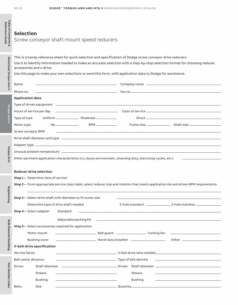
Table o
f Co
ntents &R
eference Guid
eTo
rque-A
rm II
Mo
torized To
rque-A
rm II
Torq
ue-Arm
Eng
ineeringB
ulk Material H
andling
Part Num
ber Ind
ex
G2-13 D O D G E ® TO RQ U E - A R M A N D MTA I I G E A R I N G EN G I N EER I N G C ATA LO G
SelectionScrew conveyor shaft mount speed reducers
This is a handy reference sheet for quick selection and specification of Dodge screw conveyor drive reducers.
Use it to identify information needed to make an accurate selection with a step-by-step selection format for choosing reducer, accessories and v-drive.
Use this page to make your own selections or send this form, with application data to Dodge for assistance.
Name Company name
Phone no. Fax no.
Application data
Type of driven equipment
Hours of service per day Class of service
Type of load Uniform Moderate Shock
Motor type Hp RPM Frame size Shaft size
Screw conveyor RPM
Drive shaft diameter and type
Adapter type
Unusual ambient temperature
Other pertinent application characteristics (i.e.,dusty environment, reversing duty, start/stop cycles, etc.)
Reducer drive selection
Step 1 – Determine class of service
Step 2 – From appropriate service class table, select reducer size and rotation that meets application Hp and driven RPM requirements
Step 3 – Select drive shaft with diameter to fit screw size
Determine type of drive shaft needed 3-hole standard 3-hole stainless
Step 4 – Select adapter Standard
Adjustable packing kit
Step 5 – Select accessories required for application
Motor mount Belt guard Cooling fan
Bushing cover Harsh duty breather Other
V-belt drive specification
Service factor V-belt drive ratio needed
Belt center distance Type of belt desired
Driver: Shaft diameter Driven Shaft diameter
Sheave Sheave
Bushing Bushing
Belts Size Quantity

Part
Num
ber
Ind
exEn
gin
eeri
ngB
ulk
Mat
eria
l Han
dlin
gTo
rque
-Arm
To
rque
-Arm
IIM
oto
rize
d To
rque
-Arm
IITa
ble
of
Co
nten
ts &
Ref
eren
ce G
uid
e
TO R Q U E- A R M I I G2-14
SelectionApplication classification and class numbersTorque-Arm II shaft mount speed reducers
Application classification and class numbers
For Application Class and Service, please see pages G1-6 through G1-12.

Table o
f Co
ntents &R
eference Guid
eTo
rque-A
rm II
Mo
torized To
rque-A
rm II
Torq
ue-Arm
Eng
ineeringB
ulk Material H
andling
Part Num
ber Ind
ex
G2-15 D O D G E ® TO RQ U E - A R M A N D MTA I I G E A R I N G EN G I N EER I N G C ATA LO G
SelectionTorque-Arm II shaft mount speed reducersClass I selections ★, service factor 1.0
Class I selections
MotorHp
OutputRPM
Reducerselection
Min.sheave
dia.P.D.
Coolingmethod
1/4
4-50
TA0107L31 4.0 –
TA0107L25 4.0 –
TA0107L15 4.0 –
51-80TA0107L25 4.0 –
TA0107L15 4.0 –
81-89TA0107L15 4.0 –
TA0107L09 5.3 –
90-120
TA0107L15 4.0 –
TA0107L09 5.2 –
TA0107L05 9.2 –
121-200TA0107L09 5.0 –
TA0107L05 8.3 –
201-400 TA0107L05 6.9 –
1/3
4
TA1107H31 5.0 –
TA1107H25 6.4 –
TA1107H15 5.5 –
5-50
TA0107L31 4.0 –
TA0107L25 4.0 –
TA0107L15 4.0 –
51-80TA0107L25 4.0 –
TA0107L15 4.0 –
81-89TA0107L15 4.0 –
TA0107L09 5.3 –
90-120
TA0107L15 4.0 –
TA0107L09 5.2 –
TA0107L05 9.2 –
121-200TA0107L09 5.0 –
TA0107L05 8.3 –
201-400 TA0107L05 6.9 –
1/2
4
TA2115H33 3.7 –
TA2115H25 3.3 –
TA2115H15 3.3 –
5-7
TA1107H31 5.0 –
TA1107H25 6.4 –
TA1107H15 5.5 –
8-50
TA0107L31 4.0 –
TA0107L25 4.0 –
TA0107L15 4.0 –
51-80TA0107L25 4.0 –
TA0107L15 4.0 –
81-89TA0107L15 4.0 –
TA0107L09 5.3 –
90-120
TA0107L15 4.0 –
TA0107L09 5.2 –
TA0107L05 9.2 –
121-200TA0107L09 5.0 –
TA0107L05 8.3 –
201-400 TA0107L05 6.9 –
3/4 4-6
TA2115H33 3.7 –
TA2115H25 3.3 –
TA2115H15 3.3 –
MotorHp
OutputRPM
Reducerselection
Min.sheave
dia.P.D.
Coolingmethod
3/4(cont)
7-11
TA1107H31 5.0 –
TA1107H25 6.4 –
TA1107H15 5.5 –
12-50
TA0107L31 4.0 –
TA0107L25 4.0 –
TA0107L15 4.0 –
51-80TA0107L25 4.0 –
TA0107L15 4.0 –
81-89TA0107L15 4.0 –
TA0107L09 5.3 –
90-120
TA0107L15 4.0 –
TA0107L09 5.2 –
TA0107L05 9.2 –
121-200TA0107L09 5.0 –
TA0107L05 8.3 –
201-400 TA0107L05 6.9 –
1
4-5
TA3203H32 4.6 –
TA3203H25 4.6 –
TA3203H15 4.6 –
6-8
TA2115H33 3.7 –
TA2115H25 3.3 –
TA2115H15 3.3 –
9-15
TA1107H31 5.0 –
TA1107H25 6.4 –
TA1107H15 5.5 –
16-50
TA0107L31 4.0 –
TA0107L25 4.0 –
TA0107L15 4.0 –
51-80TA0107L25 4.0 –
TA0107L15 4.0 –
81-89TA0107L15 4.0 –
TA0107L09 5.3 –
90-120
TA0107L15 4.0 –
TA0107L09 5.2 –
TA0107L05 9.2 –
121-200TA0107L09 5.0 –
TA0107L05 8.3 –
201-400 TA0107L05 6.9 –
1-1/2
4-5
TA4207H40 5.0 –
TA4207H25 5.5 –
TA4207H15 8.1 –
6-7
TA3203H32 4.6 –
TA3203H25 4.6 –
TA3203H15 4.6 –
8-12
TA2115H33 3.7 –
TA2115H25 3.3 –
TA2115H15 3.3 –
13-23
TA1107H31 4.9 –
TA1107H25 6.2 –
TA1107H15 5.5 –
MotorHp
OutputRPM
Reducerselection
Min.sheave
dia.P.D.
Coolingmethod
1-1/2(cont)
24-50
TA0107L31 4.0 –
TA0107L25 4.0 –
TA0107L15 4.0 –
51-80TA0107L25 4.0 –
TA0107L15 4.0 –
81-89TA0107L15 4.0 –
TA0107L09 5.3 –
90-120
TA0107L15 4.0 –
TA0107L09 5.2 –
TA0107L05 9.2 –
121-200TA0107L09 5.0 –
TA0107L05 8.3 –
201-400 TA0107L05 6.9 –
2
4
TA5215H40 6.8 –
TA5215H25 6.1 –
TA5215H15 7.1 –
5-6
TA4207H40 5.0 –
TA4207H25 5.5 –
TA4207H15 8.1 –
7-10
TA3203H32 4.6 –
TA3203H25 4.6 –
TA3203H15 4.6 –
11-16
TA2115H33 3.7 –
TA2115H25 3.3 –
TA2115H15 3.3 –
17
TA1107H31 4.8 –
TA2115H25 3.3 –
TA1107H15 5.4 –
18-32
TA1107H31 4.8 –
TA1107H25 5.9 –
TA1107H15 5.3 –
33-50
TA0107L31 4.0 –
TA0107L25 4.0 –
TA0107L15 4.0 –
51-80TA0107L25 4.0 –
TA0107L15 4.0 –
81-89TA0107L15 4.0 –
TA0107L09 5.3 –
90-120
TA0107L15 4.0 –
TA0107L09 5.2 –
TA0107L05 9.2 –
121-200TA0107L09 5.0 –
TA0107L05 8.3 –
201-400 TA0107L05 6.9 –
3
4-6
TA5215H40 6.8 –
TA5215H25 6.1 –
TA5215H15 7.1 –
7-10
TA4207H40 5.0 –
TA4207H25 5.5 –
TA4207H15 8.1 –
★ See Page G2-132 for lubrication for 15 RPM and slower

Part
Num
ber
Ind
exEn
gin
eeri
ngB
ulk
Mat
eria
l Han
dlin
gTo
rque
-Arm
To
rque
-Arm
IIM
oto
rize
d To
rque
-Arm
IITa
ble
of
Co
nten
ts &
Ref
eren
ce G
uid
e
TO R Q U E- A R M I I G2-16
MotorHp
OutputRPM
Reducerselection
Min.sheave
dia.P.D.
Coolingmethod
3(cont)
11-15TA3203H32 4.6 –TA3203H25 4.6 –TA3203H15 4.6 –
16-26TA2115H33 3.7 –TA2115H25 3.3 –TA2115H15 3.2 –
27-50TA1107H31 4.6 –TA1107H25 5.7 –TA1107H15 5.2 –
51-80TA0107L25 4.0 –TA0107L15 4.0 –
81-89TA0107L15 4.0 –TA0107L09 5.3 –
90-120TA0107L15 4.0 –TA0107L09 5.2 –TA0107L05 9.2 –
121-200TA0107L09 5.0 –TA0107L05 8.3 –
201-400 TA0107L05 6.9
5
4TA7315H40 6.2 –TA7315H25 6.2 –TA7315H15 6.2 –
5-6TA6307H40 6.3 –TA6307H25 6.3 –TA6307H15 6.4 –
7-10TA5215H40 6.8 –TA5215H25 6.1 –TA5215H15 7.1 –
11-16TA4207H40 5.0 –TA4207H25 5.5 –TA4207H15 8.1 –
17-25TA3203H32 4.4 –TA3203H25 4.5 –TA3203H15 4.5 –
26TA3203H32 4.2 –TA2115H25 3.2 –TA2115H15 3.1 –
27-46TA2115H33 3.6 –TA2115H25 3.2 –TA2115H15 3.1 –
47-50TA1107H31 4.4 –TA1107H25 5.4 –TA1107H15 4.9 –
51-80TA1107H25 5.4 –TA1107H15 4.9 –
81-89TA1107H15 4.6 –TA1107H09 7.7 –
90-120TA0107L15 4.0 –TA0107L09 5.2 –TA0107L05 9.2 –
121-200TA0107L09 5.0 –TA0107L05 8.3 –
201-400 TA0107L05 6.9
MotorHp
OutputRPM
Reducerselection
Min.sheave
dia.P.D.
Coolingmethod
7-1/2
4TA8407H40 6.2 –TA8407H25 6.2 –TA8407H15 6.2 –
5-6TA7315H40 6.2 –TA7315H25 6.2 –TA7315H15 6.2 –
7-9TA6307H40 6.3 –TA6307H25 6.3 –TA6307H15 6.4 –
10-15TA5215H40 6.8 –TA5215H25 6.1 –TA5215H15 7.1 –
16-25TA4207H40 4.8 –TA4207H25 5.4 –TA4207H15 7.9 –
26-39TA3203H32 4.2 –TA3203H25 4.4 –TA3203H15 4.4 –
40-50TA2115H33 3.2 –TA2115H25 3.1 –TA2115H15 3.2 –
51-72TA2115H25 3.1 –TA2115H15 3.6 –
73-80TA1107H25 5.2 –TA1107H15 4.7 –
81-89TA1107H15 4.6 –TA1107H09 7.7 –
90-120TA1107H15 4.6 –TA1107H09 7.5 –TA1107H05 12.5 –
121-145TA1107H09 7.1 –TA1107H05 11.2 –
146-163TA0107L09 4.8 –TA1107H05 10.3 –
164-200TA0107L09 4.7 –TA0107L05 7.4 –
201-400 TA0107L05 6.9
10 4TA9415H40 8.0 –TA9415H25 8.0 –TA9415H15 10.2 –
5TA8407H40 6.2 –TA8407H25 6.2 –TA8407H15 6.2 –
6-8TA7315H40 6.2 –TA7315H25 6.2 –TA7315H15 6.2 –
9-12TA6307H40 6.3 –TA6307H25 6.3 –TA6307H15 6.4 –
13-20TA5215H40 6.7 –TA5215H25 6.0 –TA5215H15 7.0 –
MotorHp
OutputRPM
Reducerselection
Min.sheave
dia.P.D.
Coolingmethod
10(cont)
21-32
TA4207H40 4.7 –
TA4207H25 5.2 –
TA4207H15 7.7 –
34-50
TA3203H32 4.1 –
TA3203H25 4.3 –
TA3203H15 4.3 –
51-55TA3203H25 4.2 –
TA3203H15 4.2 –
56-80TA2115H25 3.1 –
TA2115H15 3.6 –
81-89TA2115H15 3.7 –
TA2115H09 6.1 –
90-100
TA2115H15 3.7 –
TA2115H09 6.2 –
TA2115H05 6.5 –
101
TA1107H15 4.5 –
TA2115H09 6.2 –
TA2115H05 6.5 –
102-118
TA1107H15 4.5 –
TA1107H09 7.4 –
TA2115H05 6.6 –
119-120
TA1107H15 4.4 –
TA1107H09 7.1 –
TA1107H05 11.2 –
121-200TA1107H09 7.1 –
TA1107H05 11.2 –
201-276 TA1107H05 9.1 –
277-400 TA0107L05 5.8 –
15
4
TA10507H40 8.5 –
TA10507H25 8.5 –
TA10507H15 10.8 –
5-6
TA9415H40 8.0 –
TA9415H25 8.0 –
TA9415H15 10.2 –
7-8
TA8407H40 6.2 –
TA8407H25 6.2 –
TA8407H15 6.2 –
9-13
TA7315H40 6.2 –
TA7315H25 6.2 –
TA7315H15 6.2 –
14-18
TA6307H40 6.3 –
TA6307H25 6.3 –
TA6307H15 6.3 –
19-32
TA5215H40 6.5 –
TA5215H25 5.9 –
TA5215H15 6.8 –
33-50
TA4207H40 4.5 –
TA4207H25 5.0 –
TA4207H15 7.3 –
51-53TA4207H25 4.7 –
TA4207H15 6.8 –
SelectionTorque-Arm II shaft mount speed reducersClass I selections ★, service factor 1.0
★ See Page G2-132 for lubrication for 15 RPM and slower

Table o
f Co
ntents &R
eference Guid
eTo
rque-A
rm II
Mo
torized To
rque-A
rm II
Torq
ue-Arm
Eng
ineeringB
ulk Material H
andling
Part Num
ber Ind
ex
G2-17 D O D G E ® TO RQ U E - A R M A N D MTA I I G E A R I N G EN G I N EER I N G C ATA LO G
MotorHp
OutputRPM
Reducerselection
Min.sheave
dia.P.D.
Coolingmethod
15(cont)
54-80TA3203H25 4.1 –
TA3203H15 4.2 –
81-89TA3203H15 4.0 –
TA3203H09 5.2 –
90-92
TA3203H15 4.0 –
TA3203H09 5.3 –
TA3203H05 11.0 –
93-120
TA2115H15 3.7 –
TA2115H09 6.2 –
TA3203H05 10.4 –
121-143TA2115H09 6.1 –
TA3203H05 7.7 –
144-200TA2115H09 6.5 –
TA2115H05 6.4 –
201-400 TA2115H05 6.0 –
20
4
TA12608H40 17.2 –
TA12608H25 9.5 –
TA12608H15 13.7 –
5-6
TA10507H40 8.5 –
TA10507H25 8.5 –
TA10507H15 10.8 –
7-8
TA9415H40 8.0 –
TA9415H25 8.0 –
TA9415H15 10.2 –
9-11
TA8407H40 6.2 –
TA8407H25 6.2 –
TA8407H15 6.2 –
12-18
TA7315H40 6.2 –
TA7315H25 6.2 –
TA7315H15 6.2 –
19-25
TA6307H40 6.3 –
TA6307H25 6.3 –
TA6307H15 6.3 –
26-45
TA5215H40 6.4 –
TA5215H25 5.7 –
TA5215H15 6.7 –
46-50
TA4207H40 4.3 –
TA4207H25 4.7 –
TA4207H15 7.0 –
51-75TA4207H25 4.7 –
TA4207H15 6.8 –
76-80TA4207H25 4.4 –
TA3203H15 4.1 –
81-89TA3203H15 4.0 –
TA3203H09 5.2 –
90-103
TA3203H15 4.0 –
TA3203H09 5.4 –
TA4207H05 9.9 –
104-105
TA4207H15 6.1 –
TA3203H09 5.4 –
TA4207H05 9.6 –
MotorHp
OutputRPM
Reducerselection
Min.sheave
dia.P.D.
Coolingmethod
20(cont)
106-120TA4207H15 6.1 –TA3203H09 5.6 –TA3203H05 8.6 –
121-141TA3203H09 5.7 –TA3203H05 7.7 –
142-200TA2115H09 6.5 –TA3203H05 7.2 –
201-238 TA3203H05 7.0 –239-400 TA2115H05 5.7 –
25
4 TDT1425 † 15.0 –
5TA12608H40 17.2 –TA12608H25 9.5 –TA12608H15 13.7 –
6-7TA10507H40 8.5 –TA10507H25 8.5 –TA10507H15 10.8 –
8-10TA9415H40 8.0 –TA9415H25 8.0 –TA9415H15 10.2 –
11-15TA8407H40 6.2 –TA8407H25 6.2 –TA8407H15 6.2 –
16-23TA7315H40 6.2 –TA7315H25 6.2 –TA7315H15 6.2 –
24-32TA6307H40 6.3 –TA6307H25 6.3 –TA6307H15 6.3 –
33-50TA5215H40 6.3 –TA5215H25 5.6 –TA5215H15 6.5 –
51-58TA5215H25 5.4 –TA5215H15 6.3 –
59-80TA4207H25 4.6 –TA4207H15 6.7 –
81-89TA4207H15 6.4 –TA4207H09 10.1 –
90-110TA4207H15 6.3 –TA4207H09 9.9 –TA5215H05 13.9 –
111-120TA4207H15 6.0 –TA4207H09 9.4 –TA4207H05 9.5 –
121-163TA4207H09 9.3 –TA4207H05 9.3 –
164-200TA4207H09 8.5 –TA3203H05 7.0 –
201-400 TA3203H05 7.0 –
30
4-5 TDT1425 † 15.0 –
6TA12608H40 17.2 –TA12608H25 9.5 –TA12608H15 13.7 –
MotorHp
OutputRPM
Reducerselection
Min.sheave
dia.P.D.
Coolingmethod
30(cont)
7-9TA10507H40 8.5 –TA10507H25 8.5 –TA10507H15 10.8 –
10-12TA9415H40 8.0 –TA9415H25 8.0 –TA9415H15 10.3 –
13-18TA8407H40 6.2 –TA8407H25 6.2 –TA8407H15 6.2 –
19-28TA7315H40 6.2 –TA7315H25 6.2 –TA7315H15 6.2 –
29-30TA6307H40 6.3 –TA6307H25 6.3 –TA6307H15 6.3 –
31-39TA6307H40 6.2 –TA6307H25 6.2 –TA6307H15 6.3 –
40-50TA5215H40 6.2 –TA5215H25 5.5 –TA5215H15 6.4 –
51-72TA5215H25 5.4 –TA5215H15 6.3 –
73-80TA4207H25 4.4 –TA4207H15 6.5 –
81-89TA4207H15 6.4 –TA4207H09 10.1 –
90-120TA4207H15 6.3 –TA4207H09 9.9 –TA5215H05 13.9 –
121-132TA4207H09 9.3 –TA5215H05 11.8 –
133-200TA4207H09 9.1 –TA4207H05 9.2 –
201-215 TA4207H05 9.3 –216-400 TA3203H05 7.0 –
40
4 TDT1530 † 15.0 –5-6 TDT1425 † 15.0 –
7TA12608H40 17.2 –
TDT1425 † 15.0 –
8TA12608H40 17.2 –TA12608H25 9.5 –TA12608H15 13.7 –
9-12TA10507H40 8.5 –TA10507H25 8.5 –TA10507H15 10.8 –
13-17TA9415H40 8.0 –TA9415H25 8.0 –TA9415H15 10.5 –
18-25TA8407H40 6.2 –TA8407H25 6.2 –TA8407H15 6.2 –
★ See Page G2-132 for lubrication for 15 RPM and slower † See page G3-70 and G3-71 for information on TDT1425 and TDT1530 reducers
SelectionTorque-Arm II shaft mount speed reducersClass I selections ★, service factor 1.0

Part
Num
ber
Ind
exEn
gin
eeri
ngB
ulk
Mat
eria
l Han
dlin
gTo
rque
-Arm
To
rque
-Arm
IIM
oto
rize
d To
rque
-Arm
IITa
ble
of
Co
nten
ts &
Ref
eren
ce G
uid
e
TO R Q U E- A R M I I G2-18
MotorHp
OutputRPM
Reducerselection
Min.sheave
dia.P.D.
Coolingmethod
40(cont)
26-38
TA7315H40 6.2 –
TA7315H25 6.2 –
TA7315H15 6.2 –
39-50
TA6307H40 6.2 –
TA6307H25 6.2 –
TA6307H15 6.2 –
51-54TA6307H25 6.2 –
TA6307H15 6.2 –
55-80TA5215H25 5.4 –
TA5215H15 6.3 –
81-89TA5215H15 6.0 –
TA5215H09 9.1 –
90-102
TA5215H15 5.7 –
TA5215H09 8.9 –
TA5215H05 13.9 –
103-107
TA4207H15 6.1 –
TA5215H09 8.6 –
TA5215H05 12.9 –
108-120
TA4207H15 6.0 –
TA4207H09 9.5 –
TA5215H05 12.6 –
121-182TA4207H09 9.3 –
TA5215H05 11.8 –
183-185TA4207H09 8.1 –
TA4207H05 9.1 –
186-200TA4207H09 8.0 –
TA4207H05 9.2 –
201-400 TA4207H05 9.8 –
50
4-5 TDT1530 † 15.0 –
6-8 TDT1425 † 15.0 –
9-10
TA12608H40 17.2 –
TA12608H25 9.5 –
TA12608H15 13.7 –
11-15
TA10507H40 8.5 –
TA10507H25 8.5 –
TA10507H15 10.8 –
16-17
TA9415H40 8.0 Fan
TA9415H25 8.0 –
TA9415H15 10.5 –
18-21
TA9415H40 8.0 –
TA9415H25 8.0 –
TA9415H15 10.7 –
22-27
TA8407H40 6.2 Fan
TA8407H25 6.2 –
TA8407H15 6.2 –
28-32
TA8407H40 6.2 –
TA8407H25 6.2 –
TA8407H15 6.2 –
33-49
TA7315H40 6.2 –
TA7315H25 6.2 –
TA7315H15 6.2 –
MotorHp
OutputRPM
Reducerselection
Min.sheave
dia.P.D.
Coolingmethod
50(cont)
50TA6307H40 6.2 FanTA6307H25 6.2 –TA6307H15 6.2 –
51-69TA6307H25 6.2 –TA6307H15 6.2 –
70-80TA5215H25 5.3 FanTA5215H15 6.1 –
81-89TA5215H15 6.0 –TA5215H09 9.1 –
90-93TA5215H15 5.7 –TA5215H09 8.9 –TA6307H05 15.1 –
94-120TA5215H15 5.6 –TA5215H09 8.8 –TA5215H05 13.6 –
121-144TA5215H09 8.3 –TA5215H05 11.8 –
145-200TA4207H09 8.9 –TA5215H05 11.2 –
201-242 TA5215H05 9.9 –243-400 TA4207H05 9.7 –
60
4-6 TDT1530 † 15.0 –7-10 TDT1425 † 15.0 –
11-13TA12608H40 17.2 –TA12608H25 9.5 –TA12608H15 13.9 –
14-18TA10507H40 8.5 –TA10507H25 8.5 –TA10507H15 10.8 –
19TA9415H40 8.0 FanTA9415H25 8.0 FanTA9415H15 10.7 –
20-26TA9415H40 8.0 FanTA9415H25 8.0 –TA9415H15 10.8 –
27-30TA8407H40 6.2 FanTA8407H25 6.2 FanTA8407H15 6.2 –
31-39TA8407H40 6.2 FanTA8407H25 6.2 –TA8407H15 6.2 –
40-50TA7315H40 6.2 FanTA7315H25 6.2 –TA7315H15 6.2 –
51-60TA7315H25 6.2 –TA7315H15 6.2 –
61-80TA6307H25 6.2 –TA6307H15 6.2 –
81-88TA6307H15 6.3 –TA6307H09 9.9 –
89TA5215H15 5.7 Fan
TA6307H09 9.9 –
MotorHp
OutputRPM
Reducerselection
Min.sheave
dia.P.D.
Coolingmethod
60(cont)
90-93
TA5215H15 5.7 –
TA6307H09 10.1 –
TA6307H05 15.1 –
94-115TA5215H15 5.6 –
TA5215H09 8.8 –
116-120TA5215H15 5.1 Fan
TA5215H09 8.4 –
121-131TA5215H09 8.3 –
TA6307H05 14.5 –
132-200TA5215H09 7.9 –
TA5215H05 11.4 –
201-400 TA5215H05 9.9 –
75
5-8 TDT1530 † 15.0 –
9-13 TDT1425 † 15.0 –
14-16
TA12608H40 17.1 –
TA12608H25 9.5 –
TA12608H15 14.2 –
17-23
TA10507H40 8.5 –
TA10507H25 8.5 –
TA10507H15 10.8 –
24-33
TA9415H40 8.0 Fan
TA9415H25 8.0 Fan
TA9415H15 10.8 –
34-37
TA8407H40 6.2 Fan
TA8407H25 6.2 Fan
TA8407H15 6.2 Fan
38-49
TA8407H40 6.2 Fan
TA8407H25 6.2 Fan
TA8407H15 6.2 –
50
TA7315H40 6.2 Fan
TA7315H25 6.2 Fan
TA7315H15 6.2 –
51-77TA7315H25 6.2 Fan
TA7315H15 6.2 –
78-80TA6307H25 6.2 Fan
TA6307H15 6.2 Fan
81-89TA6307H15 6.3 Fan
TA6307H09 9.9 Fan
90-101
TA6307H15 6.5 Fan
TA6307H09 10.3 Fan
TA7315H05 14.8 –
102-120
TA6307H15 6.7 Fan
TA6307H09 10.8 Fan
TA6307H05 15.1 –
121-129TA6307H09 10.8 Fan
TA6307H05 14.5 –
130-196TA5215H09 7.9 –
TA6307H05 14.4 –
197-200TA5215H09 5.9 Fan
TA6307H05 13.9 –
201-208 TA6307H05 13.8 –
★ See Page G2-132 for lubrication for 15 RPM and slower † See page G3-70 and G3-71 for information on TDT1425 and TDT1530 reducers
SelectionTorque-Arm II shaft mount speed reducersClass I selections ★, service factor 1.0

Table o
f Co
ntents &R
eference Guid
eTo
rque-A
rm II
Mo
torized To
rque-A
rm II
Torq
ue-Arm
Eng
ineeringB
ulk Material H
andling
Part Num
ber Ind
ex
G2-19 D O D G E ® TO RQ U E - A R M A N D MTA I I G E A R I N G EN G I N EER I N G C ATA LO G
MotorHp
OutputRPM
Reducerselection
Min.sheave
dia.P.D.
Coolingmethod
209-400 TA5215H05 9.7 –
100
6-11 TDT1530 † 15.0 –
12-17 TDT1425 † 15.0 –
18-19
TA12608H40 17.1 Fan
TA12608H25 9.5 –
TA12608H15 14.4 –
20-22
TA12608H40 17.1 –
TA12608H25 9.5 –
TA12608H15 14.6 –
23-26
TA10507H40 8.5 Fan
TA10507H25 8.5 Fan
TA10507H15 10.7 –
27-31
TA10507H40 8.5 Fan
TA10507H25 8.5 –
TA10507H15 10.6 –
32-46
TA9415H40 8.0 Fan
TA9415H25 8.0 Fan
TA9415H15 10.8 Fan
47-50
TA8407H40 6.2 Fan
TA8407H25 6.2 Fan
TA8407H15 6.2 Fan
51-68TA8407H25 6.2 Fan
TA8407H15 7.0 Fan
69-80TA7315H25 6.2 Fan
TA7315H15 6.2 Fan
81-110TA7315H15 6.2 Fan
TA7315H09 8.5 Fan
111TA6307H15 6.6 Fan
TA6307H09 10.5 Fan
112-120
TA6307H15 6.7 Fan
TA6307H09 10.8 Fan
TA7315H05 13.2 –
121-157TA6307H09 10.9 Fan
TA7315H05 12.8 –
158-200TA6307H09 10.9 Fan
TA6307H05 14.2 –
201-400 TA6307H05 13.8 –
125
8-14 TDT1530 † 15.0 –
15-21 TDT1425 † 15.0 –
22-26
TA12608H40 17.1 Fan
TA12608H25 9.5 Fan
TA12608H15 14.8 Fan
27-28
TA12608H40 17.1 Fan
TA12608H25 9.5 Fan
TA12608H15 14.9 –
29
TA10507H40 8.5 Fan
TA12608H25 9.5 Fan
TA12608H15 14.9 –
30-40
TA10507H40 8.5 Fan
TA10507H25 8.5 Fan
TA10507H15 10.8 Fan
MotorHp
OutputRPM
Reducerselection
Min.sheave
dia.P.D.
Coolingmethod
125(cont)
41-50
TA9415H40 8.0 P&C
TA9415H25 8.0 P&C
TA9415H15 10.8 Fan
51-59TA9415H25 8.0 P&C
TA9415H15 10.8 Fan
60-80TA8407H25 6.2 P&C
TA8407H15 7.5 Fan
81-88 TA8407H15 7.8 Fan
89-90 TA7315H15 6.2 Fan
91-120TA7315H15 6.2 Fan
TA7315H09 8.5 Fan
121-149 TA7315H09 8.6 Fan
150-160 TA6307H09 10.9 Fan
161-200TA6307H09 10.8 Fan
TA7315H05 11.9 –
201-225 TA7315H05 11.7 –
226-368 TA6307H05 12.8 –
369-400 TA6307H05 10.9 Fan
150
9-17 TDT1530 † 15.0 –
18-26 TDT1425 † 15.0 –
27 TA12608H40 17.1 P&C
28-34
TA12608H40 17.1 Fan
TA12608H25 9.5 Fan
TA12608H15 15.1 Fan
35-36
TA10507H40 8.5 P&C
TA12608H25 9.5 Fan
TA12608H15 15.2 Fan
37-49
TA10507H40 8.5 P&C
TA10507H25 8.5 Fan
TA10507H15 11.3 –
50
TA9415H40 8.0 P&C
TA9415H25 8.0 P&C
TA9415H15 10.8 Fan
51-72TA9415H25 8.0 P&C
TA9415H15 10.8 Fan
73-80TA8407H25 6.2 P&C
TA8407H15 7.5 Fan
81-112 TA8407H15 8.6 Fan
113 TA7315H15 6.2 Fan
114-120TA7315H15 6.2 Fan
TA7315H09 8.5 Fan
121-200 TA7315H09 8.6 Fan
213-400 TA7315H05 11.5 –
200
12-23 TDT1530 † 15.0 –
24-35 TDT1425 † 15.0 –
36-47
TA12608H40 17.1 P&C
TA12608H25 9.5 Fan
TA12608H15 15.6 Fan
48-50
TA10507H40 8.5 P&C
TA12608H25 9.5 P&C
TA12608H15 15.7 Fan
MotorHp
OutputRPM
Reducerselection
Min.sheave
dia.P.D.
Coolingmethod
200(cont)
TA12608H25 9.6 FanTA12608H15 15.7 Fan
52-67TA10507H25 8.8 P&CTA10507H15 12.4 Fan
68TA9415H25 8.0 P&C
TA10507H15 12.5 Fan
69-80TA9415H25 8.0 P&CTA9415H15 10.7 P&C
81-100 TA9415H15 10.5 P&C101-120 TA8407H15 8.7 P&C172-200 TA7315H09 8.4 P&C331-400 TA7315H05 10.8 Fan
250
16-30 TDT1530 † 15.0 –31-43 TDT1425 † 15.0 Fan
44-50TA12608H40 17.1 P&CTA12608H25 9.5 P&CTA12608H15 15.7 P&C
51-67TA12608H25 10.4 P&CTA12608H15 16.1 P&C
68-75TA10507H25 9.2 P&CTA10507H15 13.0 P&C
76-80TA10507H25 9.4 P&CTA10507H15 13.4 P&C
81-90 TA10507H15 13.6 P&C91-120 TA9415H15 10.3 P&C
300
19-36 TDT1530 † 15.0 –37-52 TDT1425 † 15.0 P&C
53-80TA12608H25 10.7 P&CTA12608H15 16.1 P&C
81-83 TA12608H15 15.6 P&C84-115 TA10507H15 13.6 P&C
116-120 TA9415H15 10.2 P&C
350
23-42 TDT1530 † 15.0 Fan43-61 TDT1425 † 15.0 P&C
62-80TA12608H25 10.7 P&CTA12608H15 16.1 P&C
81-103 TA12608H15 15.6 P&C104-120 TA10507H15 13.5 P&C
400
27-50 TDT1530 † 15.0 Fan51-70 TDT1425 † 15.0 P&C
71-80TA12608H25 10.7 P&CTA12608H15 16.1 P&C
81-120 TA12608H15 15.6 P&C
450
30-31 TDT1530 † 15.0 P&C32-57 TDT1530 † 15.0 Fan59-75 TDT1425 † 15.0 P&C
84-120 TA12608H15 15.5 P&C
50034-57 TDT1530 † 15.0 P&C66-75 TDT1425 † 15.0 P&C
97-120 TA12608H15 15.1 P&C600 41-57 TDT1530 † 15.0 P&C700 50-57 TDT1530 † 15.0 P&C
★ See Page G2-132 for lubrication for 15 RPM and slower † See page G3-70 and G3-71 for information on TDT1425 and TDT1530 reducersP&C (Pump & Coolers) - Use the Dodge speed reducer auxiliary cooling package, part number 273933
SelectionTorque-Arm II shaft mount speed reducersClass I selections ★, service factor 1.0

Part
Num
ber
Ind
exEn
gin
eeri
ngB
ulk
Mat
eria
l Han
dlin
gTo
rque
-Arm
To
rque
-Arm
IIM
oto
rize
d To
rque
-Arm
IITa
ble
of
Co
nten
ts &
Ref
eren
ce G
uid
e
TO R Q U E- A R M I I G2-20
MotorHp
OutputRPM
Reducerselection
Min.sheave
dia.P.D.
Coolingmethod
3/4(cont)
9-16TA1107H31 5.0 –TA1107H25 6.4 –TA1107H15 5.5 –
17-50TA0107L31 4.0 –TA0107L25 4.0 –TA0107L15 4.0 –
51-80TA0107L25 4.0 –TA0107L15 4.0 –
81-89TA0107L15 4.0 –TA0107L09 5.3 –
90-120TA0107L15 4.0 –TA0107L09 5.2 –TA0107L05 9.2 –
121-200TA0107L09 5.0 –TA0107L05 8.3 –
201-400 TA0107L05 6.9 –
1
4TA4207H40 5.0 –TA4207H25 5.5 –TA4207H15 8.1 –
5-7TA3203H32 4.6 –TA3203H25 4.6 –TA3203H15 4.6 –
8-11TA2115H33 3.7 –TA2115H25 3.3 –TA2115H15 3.3 –
12-21TA1107H31 4.9 –TA1107H25 6.3 –TA1107H15 5.5 –
22-50TA0107L31 4.0 –TA0107L25 4.0 –TA0107L15 4.0 –
51-80TA0107L25 4.0 –TA0107L15 4.0 –
81-89TA0107L15 4.0 –TA0107L09 5.3 –
90-120TA0107L15 4.0 –TA0107L09 5.2 –TA0107L05 9.2 –
121-200TA0107L09 5.0 –TA0107L05 8.3 –
201-400 TA0107L05 6.9 –
1-1/2
4TA5215H40 6.8 –TA5215H25 6.1 –TA5215H15 7.1 –
5-7TA4207H40 5.0 –TA4207H25 5.5 –TA4207H15 8.1 –
8-10TA3203H32 4.6 –TA3203H25 4.6 –TA3203H15 4.6 –
11-17TA2115H33 3.7 –TA2115H25 3.3 –TA2115H15 3.3 –
18-34TA1107H31 4.8 –TA1107H25 5.9 –TA1107H15 5.3 –
MotorHp
OutputRPM
Reducerselection
Min.sheave
dia.P.D.
Coolingmethod
1-1/2(cont)
35-50TA0107L31 4.0 –TA0107L25 4.0 –TA0107L15 4.0 –
51-80TA0107L25 4.0 –TA0107L15 4.0 –
81-89TA0107L15 4.0 –TA0107L09 5.3 –
90-120TA0107L15 4.0 –TA0107L09 5.2 –TA0107L05 9.2 –
121-200TA0107L09 5.0 –TA0107L05 8.3 –
201-400 TA0107L05 6.9 –
2
4-5TA5215H40 6.8 –TA5215H25 6.1 –TA5215H15 7.1 –
6-9TA4207H40 5.0 –TA4207H25 5.5 –TA4207H15 8.1 –
10-14TA3203H32 4.6 –TA3203H25 4.6 –TA3203H15 4.6 –
15-24TA2115H33 3.7 –TA2115H25 3.3 –TA2115H15 3.3 –
25-46TA1107H31 4.7 –TA1107H25 5.7 –TA1107H15 5.2 –
47-50TA0107L31 4.0 –TA0107L25 4.0 –TA0107L15 4.0 –
51-80TA0107L25 4.0 –TA0107L15 4.0 –
81-89TA0107L15 4.0 –TA0107L09 5.3 –
90-120TA0107L15 4.0 –TA0107L09 5.2 –TA0107L05 9.2 –
121-200TA0107L09 5.0 –TA0107L05 8.3 –
201-400 TA0107L05 6.9 –
3
4-5TA6307H40 6.3 –TA6307H25 6.3 –TA6307H15 6.4 –
6-8TA5215H40 6.8 –TA5215H25 6.1 –TA5215H15 7.1 –
9-14TA4207H40 5.0 –TA4207H25 5.5 –TA4207H15 8.1 –
15-21TA3203H32 4.5 –TA3203H25 4.5 –TA3203H15 4.5 –
22-38TA2115H33 3.6 –TA2115H25 3.3 –TA2115H15 3.2 –
SelectionTorque-Arm II shaft mount speed reducersClass II selections ★, service factor 1.4
Class II selections
MotorHp
OutputRPM
Reducerselection
Min.sheave
dia.P.D.
Coolingmethod
1/4
4-5TA1107H31 5.0 –TA1107H25 6.4 –TA1107H15 5.5 –
6-50TA0107L31 4.0 –TA0107L25 4.0 –TA0107L15 4.0 –
51-80TA0107L25 4.0 –TA0107L15 4.0 –
81-89TA0107L15 4.0 –TA0107L09 5.3 –
90-120TA0107L15 4.0 –TA0107L09 5.2 –TA0107L05 9.2 –
121-200TA0107L09 5.0 –TA0107L05 8.3 –
201-400 TA0107L05 6.9 –
1/3
4-6TA1107H31 5.0 –TA1107H25 6.4 –TA1107H15 5.5 –
7-50TA0107L31 4.0 –TA0107L25 4.0 –TA0107L15 4.0 –
51-80TA0107L25 4.0 –TA0107L15 4.0 –
81-89TA0107L15 4.0 –TA0107L09 5.3 –
90-120TA0107L15 4.0 –TA0107L09 5.2 –TA0107L05 9.2 –
121-200TA0107L09 5.0 –TA0107L05 8.3 –
201-400 TA0107L05 6.9 –
1/2
4-5TA2115H33 3.7 –TA2115H25 3.3 –TA2115H15 3.3 –
6-10TA1107H31 5.0 –TA1107H25 6.4 –TA1107H15 5.5 –
11-50TA0107L31 4.0 –TA0107L25 4.0 –TA0107L15 4.0 –
51-80TA0107L25 4.0 –TA0107L15 4.0 –
81-89TA0107L15 4.0 –TA0107L09 5.3 –
90-120TA0107L15 4.0 –TA0107L09 5.2 –TA0107L05 9.2 –
121-200TA0107L09 5.0 –TA0107L05 8.3 –
201-400 TA0107L05 6.9 –
3/4
4-5TA3203H32 4.6 –TA3203H25 4.6 –TA3203H15 4.6 –
6-8TA2115H33 3.7 –TA2115H25 3.3 –TA2115H15 3.3 –
★ See Page G2-132 for lubrication for 15 RPM and slower

Table o
f Co
ntents &R
eference Guid
eTo
rque-A
rm II
Mo
torized To
rque-A
rm II
Torq
ue-Arm
Eng
ineeringB
ulk Material H
andling
Part Num
ber Ind
ex
G2-21 D O D G E ® TO RQ U E - A R M A N D MTA I I G E A R I N G EN G I N EER I N G C ATA LO G
MotorHp
OutputRPM
Reducerselection
Min.sheave
dia.P.D.
Coolingmethod
3(cont)
39-50TA1107H31 4.5 –TA1107H25 5.5 –TA1107H15 5.0 –
51-73TA1107H25 5.4 –TA1107H15 4.9 –
74-80TA0107L25 4.0 –TA0107L15 4.0 –
81-89TA0107L15 4.0 –TA0107L09 5.3 –
90-120TA0107L15 4.0 –TA0107L09 5.2 –TA0107L05 9.2 –
121-200TA0107L09 5.0 –TA0107L05 8.3 –
201-400 TA0107L05 6.9 –
5
4TA8407H40 6.2 –TA8407H25 6.2 –TA8407H15 6.2 –
5-6TA7315H40 6.2 –TA7315H25 6.2 –TA7315H15 6.2 –
7-8TA6307H40 6.3 –TA6307H25 6.3 –TA6307H15 6.4 –
9-14TA5215H40 6.8 –TA5215H25 6.1 –TA5215H15 7.1 –
15-23TA4207H40 4.9 –TA4207H25 5.4 –TA4207H15 7.9 –
24-36TA3203H32 4.3 –TA3203H25 4.4 –TA3203H15 4.4 –
37-50TA2115H33 3.3 –TA2115H25 3.1 –TA2115H15 3.2 –
51-67TA2115H25 3.1 –TA2115H15 3.5 –
68-80TA1107H25 5.2 –TA1107H15 4.7 –
81-89TA1107H15 4.6 –TA1107H09 7.7 –
90-120TA1107H15 4.6 –TA1107H09 7.5 –TA1107H05 12.5 –
121-131TA1107H09 7.1 –TA1107H05 11.2 –
132-146TA0107L09 5.0 –TA1107H05 10.8 –
147-200TA0107L09 4.8 –TA0107L05 7.7 –
201-400 TA0107L05 6.9 –
7-1/2 4TA9415H40 8.0 –TA9415H25 8.0 –TA9415H15 10.2 –
MotorHp
OutputRPM
Reducerselection
Min.sheave
dia.P.D.
Coolingmethod
7-1/2(cont)
5-6TA8407H40 6.2 –TA8407H25 6.2 –TA8407H15 6.2 –
7-9TA7315H40 6.2 –TA7315H25 6.2 –TA7315H15 6.2 –
10-13TA6307H40 6.3 –TA6307H25 6.3 –TA6307H15 6.4 –
14-21TA5215H40 6.7 –TA5215H25 6.0 –TA5215H15 7.0 –
22-35TA4207H40 4.7 –TA4207H25 5.2 –TA4207H15 7.7 –
36-50TA3203H32 4.1 –TA3203H25 4.3 –TA3203H15 4.3 –
51-58TA3203H25 4.2 –TA3203H15 4.2 –
59-80TA2115H25 3.1 –TA2115H15 3.6 –
81-89TA2115H15 3.7 –TA2115H09 6.1 –
90-105TA2115H15 3.7 –TA2115H09 6.2 –TA2115H05 6.5 –
106-108TA1107H15 4.5 –TA2115H09 6.2 –TA2115H05 6.5 –
109-120TA1107H15 4.5 –TA1107H09 7.3 –TA2115H05 6.6 –
121-127TA1107H09 7.1 –TA2115H05 6.6 –
128-200TA1107H09 7.0 –TA1107H05 10.9 –
201-306 TA1107H05 9.1 –307-400 TA0107L05 5.5 –
10
4TA10507H40 8.5 –TA10507H25 8.5 –TA10507H15 10.8 –
5TA9415H40 8.0 –TA9415H25 8.0 –TA9415H15 10.2 –
6-8TA8407H40 6.2 –TA8407H25 6.2 –TA8407H15 6.2 –
9-12TA7315H40 6.2 –TA7315H25 6.2 –TA7315H15 6.2 –
13-17TA6307H40 6.3 –TA6307H25 6.3 –TA6307H15 6.3 –
18-29TA5215H40 6.6 –TA5215H25 5.9 –TA5215H15 6.8 –
MotorHp
OutputRPM
Reducerselection
Min.sheave
dia.P.D.
Coolingmethod
10(cont)
30-49TA4207H40 4.5 –TA4207H25 5.0 –TA4207H15 7.4 –
50TA3203H32 4.0 –TA3203H25 4.2 –TA3203H15 4.2 –
51-80TA3203H25 4.2 –TA3203H15 4.2 –
81-84TA3203H15 4.0 –TA3203H09 5.1 –
85-89TA2115H15 3.7 –TA2115H09 6.1 –
90-120TA2115H15 3.7 –TA2115H09 6.2 –TA3203H05 11.0 –
121-127TA2115H09 6.1 –TA3203H05 7.7 –
128-162TA2115H09 6.2 –TA2115H05 6.5 –
163-200TA1107H09 6.5 –TA2115H05 6.3 –
201-209 TA2115H05 6.0 –210-400 TA1107H05 8.9 –
15
4TA12608H40 17.2 –TA12608H25 9.5 –TA12608H15 13.7 –
5-6TA10507H40 8.5 –TA10507H25 8.5 –TA10507H15 10.8 –
7-8TA9415H40 8.0 –TA9415H25 8.0 –TA9415H15 10.2 –
9-12TA8407H40 6.2 –TA8407H25 6.2 –TA8407H15 6.2 –
13-19TA7315H40 6.2 –TA7315H25 6.2 –TA7315H15 6.2 –
20-26TA6307H40 6.3 –TA6307H25 6.3 –TA6307H15 6.3 –
27-47TA5215H40 6.4 –TA5215H25 5.7 –TA5215H15 6.6 –
48-50TA4207H40 4.2 –TA4207H25 4.7 –TA4207H15 6.9 –
51-80TA4207H25 4.7 –TA4207H15 6.8 –
81TA3203H15 4.0 –TA4207H09 10.1 –
82-89TA3203H15 4.0 –TA3203H09 5.2 –
90-92TA3203H15 4.0 –TA3203H09 5.3 –TA5215H05 13.9 –
★ See Page G2-132 for lubrication for 15 RPM and slower
SelectionTorque-Arm II shaft mount speed reducersClass II selections ★, service factor 1.4

Part
Num
ber
Ind
exEn
gin
eeri
ngB
ulk
Mat
eria
l Han
dlin
gTo
rque
-Arm
To
rque
-Arm
IIM
oto
rize
d To
rque
-Arm
IITa
ble
of
Co
nten
ts &
Ref
eren
ce G
uid
e
TO R Q U E- A R M I I G2-22
MotorHp
OutputRPM
Reducerselection
Min.sheave
dia.P.D.
Coolingmethod
15(cont)
93-118TA3203H15 4.0 –TA3203H09 5.5 –TA4207H05 9.8 –
119-120TA3203H15 4.0 –TA3203H09 5.6 –TA3203H05 7.7 –
121-149TA3203H09 5.7 –TA3203H05 7.7 –
150-200TA2115H09 6.5 –TA3203H05 7.0 –
201-260 TA3203H05 7.0 –261-400 TA2115H05 5.6 –
20
4 TDT1425 † 15.0 –
5TA12608H40 17.2 –TA12608H25 9.5 –TA12608H15 13.7 –
6-8TA10507H40 8.5 –TA10507H25 8.5 –TA10507H15 10.8 –
9-11TA9415H40 8.0 –TA9415H25 8.0 –TA9415H15 10.3 –
12-17TA8407H40 6.2 –TA8407H25 6.2 –TA8407H15 6.2 –
18-26TA7315H40 6.2 –TA7315H25 6.2 –TA7315H15 6.2 –
27-36TA6307H40 6.3 –TA6307H25 6.3 –TA6307H15 6.3 –
37-50TA5215H40 6.2 –TA5215H25 5.6 –TA5215H15 6.5 –
51-67TA5215H25 5.4 –TA5215H15 6.3 –
68-80TA4207H25 4.5 –TA4207H15 6.6 –
81-89TA4207H15 6.4 –TA4207H09 10.1 –
90-115TA4207H15 6.3 –TA4207H09 9.9 –TA5215H05 13.9 –
116-120TA4207H15 5.9 –TA3203H09 5.6 –TA5215H05 12.1 –
121-123TA3203H09 5.6 –TA5215H05 11.8 –
124-194TA3203H09 5.7 –TA4207H05 9.3 –
195-200TA3203H09 5.5 –TA3203H05 7.0 –
201-400 TA3203H05 7.0 –
25
4-6 TDT1425 † 15.0 –
7TA12608H40 17.2 –TA12608H25 9.5 –TA12608H15 13.7 –
MotorHp
OutputRPM
Reducerselection
Min.sheave
dia.P.D.
Coolingmethod
25(cont)
8-10TA10507H40 8.5 –TA10507H25 8.5 –TA10507H15 10.8 –
11-14TA9415H40 8.0 –TA9415H25 8.0 –TA9415H15 10.4 –
15-21TA8407H40 6.2 –TA8407H25 6.2 –TA8407H15 6.2 –
22-33TA7315H40 6.2 –TA7315H25 6.2 –TA7315H15 6.2 –
34-46TA6307H40 6.2 –TA6307H25 6.2 –TA6307H15 6.2 –
47-50TA5215H40 6.1 –TA5215H25 5.5 –TA5215H15 6.3 –
51-80TA5215H25 5.4 –TA5215H15 6.3 –
81-87TA5215H15 6.0 –TA5215H09 9.1 –
88-89TA4207H15 6.3 –TA5215H09 8.9 –
90-91TA4207H15 6.3 –TA5215H09 8.9 –TA5215H05 13.9 –
92-120TA4207H15 6.3 –TA4207H09 9.8 –TA5215H05 13.7 –
121-154TA4207H09 9.3 –TA5215H05 11.8 –
155-200TA4207H09 8.7 –TA4207H05 9.2 –
201-269 TA4207H05 9.8 –270-400 TA3203H05 7.0 –
30
4 TDT1530 † 15.0 –5-7 TDT1425 † 15.0 –
8TA12608H40 17.2 –TA12608H25 9.5 –TA12608H15 13.7 –
9-12TA10507H40 8.5 –TA10507H25 8.5 –TA10507H15 10.8 –
13-18TA9415H40 8.0 –TA9415H25 8.0 –TA9415H15 10.6 –
19-26TA8407H40 6.2 –TA8407H25 6.2 –TA8407H15 6.2 –
27-41TA7315H40 6.2 –TA7315H25 6.2 –TA7315H15 6.2 –
42-50TA6307H40 6.2 –TA6307H25 6.2 –TA6307H15 6.2 –
MotorHp
OutputRPM
Reducerselection
Min.sheave
dia.P.D.
Coolingmethod
30(cont)
51-56TA6307H25 6.2 –TA6307H15 6.2 –
57-80TA5215H25 5.4 –TA5215H15 6.2 –
81-89TA5215H15 6.0 –TA5215H09 9.1 –
90-110TA5215H15 5.7 –TA5215H09 8.9 –TA5215H05 13.9 –
111-114TA4207H15 6.0 –TA5215H09 8.5 –TA5215H05 12.4 –
115-120TA4207H15 5.9 –TA4207H09 9.4 –TA5215H05 12.1 –
121-195TA4207H09 9.3 –TA5215H05 11.8 –
196-200TA4207H09 7.8 –TA4207H05 9.2 –
201-348 TA4207H05 9.8 –349-400 TA3203H05 7.0 –
40
4-6 TDT1530 † 15.0 –7-9 TDT1425 † 15.0 –
10-12TA12608H40 17.2 –TA12608H25 9.5 –TA12608H15 13.9 –
13-17TA10507H40 8.5 –TA10507H25 8.5 –TA10507H15 10.8 –
18-24TA9415H40 8.0 –TA9415H25 8.0 –TA9415H15 10.7 –
25-36TA8407H40 6.2 –TA8407H25 6.2 –TA8407H15 6.2 –
37-50TA7315H40 6.2 –TA7315H25 6.2 –TA7315H15 6.2 –
51-56TA7315H25 6.2 –TA7315H15 6.2 –
57-78TA6307H25 6.2 –TA6307H15 6.2 –
79-80TA5215H25 5.2 –TA5215H15 6.0 –
81-85TA5215H15 6.0 –
TA6307H09 9.8 –
86-89TA5215H15 5.8 –TA5215H09 9.0 –
90-112TA5215H15 5.7 –TA5215H09 8.9 –TA6307H05 15.1 –
113-120TA5215H15 5.1 –TA5215H09 8.4 –TA5215H05 12.3 –
121-173TA5215H09 8.3 –TA5215H05 11.8 –
★ See Page G2-132 for lubrication for 15 RPM and slower † See page G3-70 and G3-71 for information on TDT1425 and TDT1530 reducers
SelectionTorque-Arm II shaft mount speed reducersClass II selections ★, service factor 1.4

Table o
f Co
ntents &R
eference Guid
eTo
rque-A
rm II
Mo
torized To
rque-A
rm II
Torq
ue-Arm
Eng
ineeringB
ulk Material H
andling
Part Num
ber Ind
ex
G2-23 D O D G E ® TO RQ U E - A R M A N D MTA I I G E A R I N G EN G I N EER I N G C ATA LO G
MotorHp
OutputRPM
Reducerselection
Min.sheave
dia.P.D.
Coolingmethod
40(cont)
174-200TA4207H09 8.2 –TA5215H05 10.4 –
201-299 TA5215H05 9.9 –300-400 TA4207H05 8.8 –
50
5-8 TDT1530 † 15.0 –9-12 TDT1425 † 15.0 –
13-15TA12608H40 17.1 –TA12608H25 9.5 –TA12608H15 14.1 –
16-21TA10507H40 8.5 –TA10507H25 8.5 –TA10507H15 10.8 –
22-31TA9415H40 8.0 –TA9415H25 8.0 –TA9415H15 10.8 –
32-43TA8407H40 6.2 –TA8407H25 6.2 –TA8407H15 6.2 –
44-46TA8407H40 6.2 FanTA8407H25 6.2 –TA8407H15 6.2 –
47-50TA7315H40 6.2 –TA7315H25 6.2 –TA7315H15 6.2 –
51-71TA7315H25 6.2 –TA7315H15 6.2 –
72-80TA6307H25 6.2 –TA6307H15 6.2 –
81-89TA6307H15 6.3 –TA6307H09 9.9 –
90-91TA6307H15 6.3 –TA6307H09 10.0 –TA7315H05 14.8 –
92-114TA6307H15 6.6 –TA6307H09 10.6 –TA6307H05 15.1 –
115-116TA6307H15 6.7 –TA5215H09 8.4 –TA6307H05 14.7 –
117-120TA5215H15 5.1 –TA5215H09 8.4 –TA6307H05 14.6 –
121-177TA5215H09 8.3 –TA6307H05 14.5 –
178-200TA5215H09 6.3 –TA5215H05 10.4 –
201-400 TA5215H05 9.9 –
60
5-9 TDT1530 † 15.0 –10-14 TDT1425 † 15.0 –
15-18TA12608H40 17.1 –TA12608H25 9.5 –TA12608H15 14.3 –
19-26TA10507H40 8.5 –TA10507H25 8.5 –TA10507H15 10.8 –
MotorHp
OutputRPM
Reducerselection
Min.sheave
dia.P.D.
Coolingmethod
60(cont)
27-38TA9415H40 8.0 FanTA9415H25 8.0 –TA9415H15 10.8 –
39-50TA8407H40 6.2 FanTA8407H25 6.2 –TA8407H15 6.2 –
51-56TA8407H25 6.2 –TA8407H15 6.5 –
57-80TA7315H25 6.2 –TA7315H15 6.2 –
81-89TA7315H15 6.2 –TA7315H09 8.1 –
90-120TA6307H15 6.7 –TA6307H09 10.8 –TA7315H05 14.8 –
121TA6307H09 10.8 –TA7315H05 12.8 –
122-195TA6307H09 10.9 –TA6307H05 14.5 –
196-199TA6307H09 10.1 FanTA6307H05 13.9 –
200TA5215H09 5.8 –TA6307H05 13.8 –
201-282 TA6307H05 13.8 –283-400 TA5215H05 8.4 –
75
7-12 TDT1530 † 15.0 –13-18 TDT1425 † 15.0 –
19-23TA12608H40 17.1 –TA12608H25 9.5 –TA12608H15 14.6 –
24TA10507H40 8.5 –TA12608H25 9.5 –TA12608H15 14.7 –
25-33TA10507H40 8.5 –TA10507H25 8.5 –TA10507H15 10.7 –
34-48TA9415H40 8.0 FanTA9415H25 8.0 FanTA9415H15 10.8 –
49TA8407H40 6.2 FanTA8407H25 6.2 FanTA9415H15 10.8 –
50TA8407H40 6.2 FanTA8407H25 6.2 FanTA8407H15 6.2 –
51-72TA8407H25 6.2 FanTA8407H15 7.2 –
73-80TA7315H25 6.2 FanTA7315H15 6.2 –
81-111TA7315H15 6.2 –TA7315H09 8.5 –
112-117TA7315H15 6.2 –TA7315H09 8.5 –
118-120TA6307H15 6.7 FanTA6307H09 10.8 Fan
121-169TA6307H09 10.9 FanTA7315H05 12.8 –
MotorHp
OutputRPM
Reducerselection
Min.sheave
dia.P.D.
Coolingmethod
75(cont)
170-200TA6307H09 10.7 FanTA6307H05 14.0 –
201-400 TA6307H05 13.8 –
100
8-16 TDT1530 † 15.0 –17-24 TDT1425 † 15.0 –
25-32TA12608H40 17.1 –TA12608H25 9.5 –TA12608H15 15.1 –
33TA10507H40 8.5 FanTA12608H25 9.5 –TA12608H15 15.1 –
34-45TA10507H40 8.5 FanTA10507H25 8.5 –TA10507H15 11.1 –
46-50TA9415H40 8.0 FanTA9415H25 8.0 FanTA9415H15 10.8 Fan
51-67TA9415H25 8.0 FanTA9415H15 10.8 Fan
68-80TA8407H25 6.2 FanTA8407H15 7.5 Fan
81-102 TA8407H15 8.3 Fan103 TA7315H15 6.2 Fan
104-120TA7315H15 6.2 FanTA7315H09 8.5 Fan
121-180 TA7315H09 8.6 Fan181-190 TA6307H09 10.4 Fan
191-200TA6307H09 10.2 FanTA7315H05 11.7 –
201-274 TA7315H05 11.7 –275-400 TA6307H05 12.0 –
125
11-20 TDT1530 † 15.0 –21-30 TDT1425 † 15.0 –
31-41TA12608H40 17.1 FanTA12608H25 9.5 –TA12608H15 15.4 –
42-43TA10507H40 8.5 FanTA12608H25 9.5 –TA12608H15 15.5 –
44-50TA10507H40 8.5 FanTA10507H25 8.5 FanTA10507H15 11.3 Fan
51-58TA10507H25 8.5 FanTA10507H15 11.8 Fan
59-80TA9415H25 8.0 FanTA9415H15 10.8 Fan
81-85 TA9415H15 10.5 Fan86-120 TA8407H15 8.7 Fan
141-200 TA7315H09 8.6 Fan272-400 TA7315H05 10.9 –
150
13-25 TDT1530 † 15.0 –26-36 TDT1425 † 15.0 –
37-50TA12608H40 17.1 FanTA12608H25 9.5 FanTA12608H15 15.7 Fan
51-54TA12608H25 9.6 FanTA12608H15 15.8 Fan
★ See Page G2-132 for lubrication for 15 RPM and slower † See page G3-70 and G3-71 for information on TDT1425 and TDT1530 reducers
SelectionTorque-Arm II shaft mount speed reducersClass II selections ★, service factor 1.4

Part
Num
ber
Ind
exEn
gin
eeri
ngB
ulk
Mat
eria
l Han
dlin
gTo
rque
-Arm
To
rque
-Arm
IIM
oto
rize
d To
rque
-Arm
IITa
ble
of
Co
nten
ts &
Ref
eren
ce G
uid
e
TO R Q U E- A R M I I G2-24
MotorHp
OutputRPM
Reducerselection
Min.sheave
dia.P.D.
Coolingmethod
150(cont)
55-71TA10507H25 9.0 FanTA10507H15 12.7 Fan
72TA9415H25 8.0 P&C
TA10507H15 12.8 Fan
73-80TA9415H25 8.0 P&CTA9415H15 10.6 Fan
81-105 TA9415H15 10.5 Fan106-120 TA8407H15 8.7 Fan189-200 TA7315H09 8.2 Fan368-400 TA7315H05 10.1 –
200
18-33 TDT1530 † 15.0 –34-49 TDT1425 † 15.0 Fan
50TA12608H40 17.1 P&CTA12608H25 9.5 FanTA12608H15 15.7 Fan
51-76TA12608H25 10.7 FanTA12608H15 16.1 Fan
77-80TA10507H25 9.4 P&CTA10507H15 13.4 Fan
81-105 TA10507H15 13.6 Fan106-120 TA9415H15 10.2 P&C
250
23-42 TDT1530 † 15.0 –43-61 TDT1425 † 15.0 P&C
62-80TA12608H25 10.7 P&CTA12608H15 16.1 P&C
81-103 TA12608H15 15.6 P&C104-120 TA10507H15 13.5 P&C
300
28-53 TDT1530 † 15.0 –54-75 TDT1425 † 15.0 P&C
76-80TA12608H25 10.7 P&CTA12608H15 15.8 P&C
81-120 TA12608H15 15.6 P&C
35033-57 TDT1530 † 15.0 –66-75 TDT1425 † 15.0 P&C
94-120 TA12608H15 15.2 P&C
40038-57 TDT1530 † 15.0 Fan
114-120 TA12608H15 15.1 P&C450 43-57 TDT1530 † 15.0 Fan500 50-57 TDT1530 † 15.0 Fan
SelectionTorque-Arm II shaft mount speed reducersClass II selections ★, service factor 1.4
★ See Page G2-132 for lubrication for 15 RPM and slower † See page G3-70 and G3-71 for information on TDT1425 and TDT1530 reducersP&C (Pump & Coolers) - Use the Dodge speed reducer auxiliary cooling package, part number 273933

Table o
f Co
ntents &R
eference Guid
eTo
rque-A
rm II
Mo
torized To
rque-A
rm II
Torq
ue-Arm
Eng
ineeringB
ulk Material H
andling
Part Num
ber Ind
ex
G2-25 D O D G E ® TO RQ U E - A R M A N D MTA I I G E A R I N G EN G I N EER I N G C ATA LO G
SelectionTorque-Arm II shaft mount speed reducersClass III selections ★, service factor 2.0
Class III selections
MotorHp
OutputRPM
Reducerselection
Min.sheave
dia.P.D.
Coolingmethod
1/4
4TA2115H33 3.7 –TA2115H25 3.3 –TA2115H15 3.3 –
5-7TA1107H31 5.0 –TA1107H25 6.4 –TA1107H15 5.5 –
8-50TA0107L31 4.0 –TA0107L25 4.0 –TA0107L15 4.0 –
51-80TA0107L25 4.0 –TA0107L15 4.0 –
81-89TA0107L15 4.0 –TA0107L09 5.3 –
90-120TA0107L15 4.0 –TA0107L09 5.2 –TA0107L05 9.2 –
121-200TA0107L09 5.0 –TA0107L05 8.3 –
201-400 TA0107L05 6.9 –
1/3
4-5TA2115H33 3.7 –TA2115H25 3.3 –TA2115H15 3.3 –
6-9TA1107H31 5.0 –TA1107H25 6.4 –TA1107H15 5.5 –
10-50TA0107L31 4.0 –TA0107L25 4.0 –TA0107L15 4.0 –
51-80TA0107L25 4.0 –TA0107L15 4.0 –
81-89TA0107L15 4.0 –TA0107L09 5.3 –
90-120TA0107L15 4.0 –TA0107L09 5.2 –TA0107L05 9.2 –
121-200TA0107L09 5.0 –TA0107L05 8.3 –
201-400 TA0107L05 6.9 –
1/2
4-5TA3203H32 4.6 –TA3203H25 4.6 –TA3203H15 4.6 –
6-8TA2115H33 3.7 –TA2115H25 3.3 –TA2115H15 3.3 –
9-15TA1107H31 5.0 –TA1107H25 6.4 –TA1107H15 5.5 –
16-50TA0107L31 4.0 –TA0107L25 4.0 –TA0107L15 4.0 –
51-80TA0107L25 4.0 –TA0107L15 4.0 –
81-89TA0107L15 4.0 –TA0107L09 5.3 –
90-120TA0107L15 4.0 –TA0107L09 5.2 –TA0107L05 9.2 –
121-200TA0107L09 5.0 –TA0107L05 8.3 –
201-400 TA0107L05 6.9 –
MotorHp
OutputRPM
Reducerselection
Min.sheave
dia.P.D.
Coolingmethod
3/4
4-5TA4207H40 5.0 –TA4207H25 5.5 –TA4207H15 8.1 –
6-7TA3203H32 4.6 –TA3203H25 4.6 –TA3203H15 4.6 –
8-12TA2115H33 3.7 –TA2115H25 3.3 –TA2115H15 3.3 –
13-23TA1107H31 4.9 –TA1107H25 6.2 –TA1107H15 5.5 –
24-50TA0107L31 4.0 –TA0107L25 4.0 –TA0107L15 4.0 –
51-80TA0107L25 4.0 –TA0107L15 4.0 –
81-89TA0107L15 4.0 –TA0107L09 5.3 –
90-120TA0107L15 4.0 –TA0107L09 5.2 –TA0107L05 9.2 –
121-200TA0107L09 5.0 –TA0107L05 8.3 –
201-400 TA0107L05 6.9 –
1
4TA5215H40 6.8 –TA5215H25 6.1 –TA5215H15 7.1 –
5-6TA4207H40 5.0 –TA4207H25 5.5 –TA4207H15 8.1 –
7-10TA3203H32 4.6 –TA3203H25 4.6 –TA3203H15 4.6 –
11-16TA2115H33 3.7 –TA2115H25 3.3 –TA2115H15 3.3 –
17TA1107H31 4.8 –TA2115H25 3.3 –TA1107H15 5.4 –
18-32TA1107H31 4.8 –TA1107H25 5.9 –TA1107H15 5.3 –
33-50TA0107L31 4.0 –TA0107L25 4.0 –TA0107L15 4.0 –
51-80TA0107L25 4.0 –TA0107L15 4.0 –
81-89TA0107L15 4.0 –TA0107L09 5.3 –
90-120TA0107L15 4.0 –TA0107L09 5.2 –TA0107L05 9.2 –
121-200TA0107L09 5.0 –TA0107L05 8.3 –
201-400 TA0107L05 6.9 –
1-1/2 4-6TA5215H40 6.8 –TA5215H25 6.1 –TA5215H15 7.1 –
MotorHp
OutputRPM
Reducerselection
Min.sheave
dia.P.D.
Coolingmethod
1-1/2(cont)
7-10TA4207H40 5.0 –TA4207H25 5.5 –TA4207H15 8.1 –
11-15TA3203H32 4.6 –TA3203H25 4.6 –TA3203H15 4.6 –
16-26TA2115H33 3.7 –TA2115H25 3.3 –TA2115H15 3.2 –
27-50TA1107H31 4.6 –TA1107H25 5.7 –TA1107H15 5.2 –
51-80TA0107L25 4.0 –TA0107L15 4.0 –
81-89TA0107L15 4.0 –TA0107L09 5.3 –
90-120TA0107L15 4.0 –TA0107L09 5.2 –TA0107L05 9.2 –
121-200TA0107L09 5.0 –TA0107L05 8.3 –
201-400 TA0107L05 6.9 –
2
4-5TA6307H40 6.3 –TA6307H25 6.3 –TA6307H15 6.4 –
6-8TA5215H40 6.8 –TA5215H25 6.1 –TA5215H15 7.1 –
9-13TA4207H40 5.0 –TA4207H25 5.5 –TA4207H15 8.1 –
14-20TA3203H32 4.5 –TA3203H25 4.5 –TA3203H15 4.6 –
21-36TA2115H33 3.6 –TA2115H25 3.3 –TA2115H15 3.2 –
37-50TA1107H31 4.5 –TA1107H25 5.6 –TA1107H15 5.0 –
51-69TA1107H25 5.4 –TA1107H15 4.9 –
70-80TA0107L25 4.0 –TA0107L15 4.0 –
81-89TA0107L15 4.0 –TA0107L09 5.3 –
90-120TA0107L15 4.0 –TA0107L09 5.2 –TA0107L05 9.2 –
121-200TA0107L09 5.0 –TA0107L05 8.3 –
201-400 TA0107L05 6.9 –
3
4-5TA7315H40 6.2 –TA7315H25 6.2 –TA7315H15 6.2 –
6-7TA6307H40 6.3 –TA6307H25 6.3 –TA6307H15 6.4 –
★ See Page G2-132 for lubrication for 15 RPM and slower

Part
Num
ber
Ind
exEn
gin
eeri
ngB
ulk
Mat
eria
l Han
dlin
gTo
rque
-Arm
To
rque
-Arm
IIM
oto
rize
d To
rque
-Arm
IITa
ble
of
Co
nten
ts &
Ref
eren
ce G
uid
e
TO R Q U E- A R M I I G2-26
MotorHp
OutputRPM
Reducerselection
Min.sheave
dia.P.D.
Coolingmethod
3(cont)
8-12TA5215H40 6.8 –TA5215H25 6.1 –TA5215H15 7.1 –
13-20TA4207H40 4.9 –TA4207H25 5.5 –TA4207H15 8.0 –
21-30TA3203H32 4.3 –TA3203H25 4.4 –TA3203H15 4.4 –
31TA3203H32 4.1 –TA2115H25 3.1 –TA2115H15 3.1 –
32-50TA2115H33 3.5 –TA2115H25 3.1 –TA2115H15 3.2 –
51-56TA2115H25 3.1 –TA2115H15 3.3 –
57-80TA1107H25 5.3 –TA1107H15 4.8 –
81-89TA1107H15 4.6 –TA1107H09 7.7 –
90-109TA1107H15 4.6 –TA1107H09 7.5 –TA1107H05 12.5 –
110-113TA1107H15 4.5 –TA0107L09 5.1 –TA1107H05 11.6 –
114TA0107L15 4.0 –TA0107L09 5.1 –TA1107H05 11.4 –
115-120TA0107L15 4.0 –TA0107L09 5.1 –TA0107L05 8.4 –
121-200TA0107L09 5.0 –TA0107L05 8.3 –
201-400 TA0107L05 6.9 –
5
4TA9415H40 8.0 –TA9415H25 8.0 –TA9415H15 10.2 –
5TA8407H40 6.2 –TA8407H25 6.2 –TA8407H15 6.2 –
6-8TA7315H40 6.2 –TA7315H25 6.2 –TA7315H15 6.2 –
9-12TA6307H40 6.3 –TA6307H25 6.3 –TA6307H15 6.4 –
13-20TA5215H40 6.7 –TA5215H25 6.0 –TA5215H15 7.0 –
21-33TA4207H40 4.7 –TA4207H25 5.2 –TA4207H15 7.7 –
34-50TA3203H32 4.1 –TA3203H25 4.3 –TA3203H15 4.3 –
51-55TA3203H25 4.2 –TA3203H15 4.2 –
MotorHp
OutputRPM
Reducerselection
Min.sheave
dia.P.D.
Coolingmethod
5(cont)
56-80TA2115H25 3.1 –TA2115H15 3.6 –
81-89TA2115H15 3.7 –TA2115H09 6.1 –
90-100TA2115H15 3.7 –TA2115H09 6.2 –TA2115H05 6.5 –
101TA1107H15 4.5 –TA2115H09 6.2 –TA2115H05 6.5 –
102-118TA1107H15 4.5 –TA1107H09 7.4 –TA2115H05 6.6 –
119-120TA1107H15 4.4 –TA1107H09 7.1 –TA1107H05 11.2 –
121-200TA1107H09 7.1 –TA1107H05 11.2 –
201-276 TA1107H05 9.1 –277-400 TA0107L05 5.8 –
7-1/2
4TA10507H40 8.5 –TA10507H25 8.5 –TA10507H15 10.8 –
5-6TA9415H40 8.0 –TA9415H25 8.0 –TA9415H15 10.2 –
7-8TA8407H40 6.2 –TA8407H25 6.2 –TA8407H15 6.2 –
9-13TA7315H40 6.2 –TA7315H25 6.2 –TA7315H15 6.2 –
14-18TA6307H40 6.3 –TA6307H25 6.3 –TA6307H15 6.3 –
19-32TA5215H40 6.5 –TA5215H25 5.9 –TA5215H15 6.8 –
33-50TA4207H40 4.5 –TA4207H25 5.0 –TA4207H15 7.3 –
51-53TA4207H25 4.7 –TA4207H15 6.8 –
54-80TA3203H25 4.1 –TA3203H15 4.2 –
81-89TA3203H15 4.0 –TA3203H09 5.2 –
90-92TA3203H15 4.0 –TA3203H09 5.3 –TA3203H05 11.0 –
93-120TA2115H15 3.7 –TA2115H09 6.2 –TA3203H05 10.4 –
121-143TA2115H09 6.1 –TA3203H05 7.7 –
144-181TA2115H09 6.3 –TA2115H05 6.4 –
MotorHp
OutputRPM
Reducerselection
Min.sheave
dia.P.D.
Coolingmethod
7-1/2(cont)
182-200TA1107H09 6.2 –TA2115H05 6.2 –
201-237 TA2115H05 6.0 –238-400 TA1107H05 8.4 –
10
4TA12608H40 17.2 –TA12608H25 9.5 –TA12608H15 13.7 –
5-6TA10507H40 8.5 –TA10507H25 8.5 –TA10507H15 10.8 –
7-8TA9415H40 8.0 –TA9415H25 8.0 –TA9415H15 10.2 –
9-11TA8407H40 6.2 –TA8407H25 6.2 –TA8407H15 6.2 –
12-18TA7315H40 6.2 –TA7315H25 6.2 –TA7315H15 6.2 –
19-25TA6307H40 6.3 –TA6307H25 6.3 –TA6307H15 6.3 –
26-45TA5215H40 6.4 –TA5215H25 5.7 –TA5215H15 6.7 –
46-50TA4207H40 4.3 –TA4207H25 4.7 –TA4207H15 7.0 –
51-75TA4207H25 4.7 –TA4207H15 6.8 –
76-80TA3203H25 4.0 –TA3203H15 4.1 –
81-89TA3203H15 4.0 –TA3203H09 5.2 –
90-105TA3203H15 4.0 –TA3203H09 5.4 –TA4207H05 9.9 –
106-120TA3203H15 4.0 –TA3203H09 5.6 –TA3203H05 8.6 –
121-141TA3203H09 5.7 –TA3203H05 7.7 –
142-200TA2115H09 6.5 –TA3203H05 7.2 –
201-238 TA3203H05 7.0 –239-400 TA2115H05 5.7 –
15
4-5 TDT1425 † 15.0 –
6TA12608H40 17.2 –TA12608H25 9.5 –TA12608H15 13.7 –
7-9TA10507H40 8.5 –TA10507H25 8.5 –TA10507H15 10.8 –
10-12TA9415H40 8.0 –TA9415H25 8.0 –TA9415H15 10.3 –
SelectionTorque-Arm II shaft mount speed reducersClass III selections ★, service factor 2.0
★ See Page G2-132 for lubrication for 15 RPM and slower † See page G3-70 and G3-71 for information on TDT1425 and TDT1530 reducers

Table o
f Co
ntents &R
eference Guid
eTo
rque-A
rm II
Mo
torized To
rque-A
rm II
Torq
ue-Arm
Eng
ineeringB
ulk Material H
andling
Part Num
ber Ind
ex
G2-27 D O D G E ® TO RQ U E - A R M A N D MTA I I G E A R I N G EN G I N EER I N G C ATA LO G
MotorHp
OutputRPM
Reducerselection
Min.sheave
dia.P.D.
Coolingmethod
15(cont)
13-18TA8407H40 6.2 –TA8407H25 6.2 –TA8407H15 6.2 –
19-28TA7315H40 6.2 –TA7315H25 6.2 –TA7315H15 6.2 –
29-39TA6307H40 6.3 –TA6307H25 6.3 –TA6307H15 6.3 –
40-50TA5215H40 6.2 –TA5215H25 5.5 –TA5215H15 6.4 –
51-72TA5215H25 5.4 –TA5215H15 6.3 –
73-80TA4207H25 4.4 –TA4207H15 6.5 –
81-89TA4207H15 6.4 –TA4207H09 10.1 –
90-120TA4207H15 6.3 –TA4207H09 9.9 –TA5215H05 13.9 –
121-125TA4207H09 9.3 –TA5215H05 11.8 –
126-132TA3203H09 5.7 –TA5215H05 11.6 –
133-200TA3203H09 5.7 –TA4207H05 9.2 –
201-215 TA4207H05 9.3 –216-400 TA3203H05 7.0 –
20
4 TDT1530 † 15.0 –5-6 TDT1425 † 15.0 –
7TA12608H40 17.2 –
TDT1425 † 15.0 –
8TA12608H40 17.2 –TA12608H25 9.5 –TA12608H15 13.7 –
9-12TA10507H40 8.5 –TA10507H25 8.5 –TA10507H15 10.8 –
13-17TA9415H40 8.0 –TA9415H25 8.0 –TA9415H15 10.5 –
18-25TA8407H40 6.2 –TA8407H25 6.2 –TA8407H15 6.2 –
26-38TA7315H40 6.2 –TA7315H25 6.2 –TA7315H15 6.2 –
39-50TA6307H40 6.2 –TA6307H25 6.2 –TA6307H15 6.2 –
51-54TA6307H25 6.2 –TA6307H15 6.2 –
55-80TA5215H25 5.4 –TA5215H15 6.3 –
81-89TA5215H15 6.0 –TA5215H09 9.1 –
MotorHp
OutputRPM
Reducerselection
Min.sheave
dia.P.D.
Coolingmethod
20(cont)
90-102TA5215H15 5.7 –TA5215H09 8.9 –TA5215H05 13.9 –
103-107TA4207H15 6.1 –TA5215H09 8.6 –TA5215H05 12.9 –
108-120TA4207H15 6.0 –TA4207H09 9.5 –TA5215H05 12.6 –
121-182TA4207H09 9.3 –TA5215H05 11.8 –
183-200TA4207H09 8.1 –TA4207H05 9.2 –
201-324 TA4207H05 9.8 –325-400 TA3203H05 7.0 –
25
4-5 TDT1530 † 15.0 –6-8 TDT1425 † 15.0 –
9-10TA12608H40 17.2 –TA12608H25 9.5 –TA12608H15 13.7 –
11-15TA10507H40 8.5 –TA10507H25 8.5 –TA10507H15 10.8 –
16-21TA9415H40 8.0 –TA9415H25 8.0 –TA9415H15 10.7 –
22-32TA8407H40 6.2 –TA8407H25 6.2 –TA8407H15 6.2 –
33-49TA7315H40 6.2 –TA7315H25 6.2 –TA7315H15 6.2 –
50TA6307H40 6.2 –TA6307H25 6.2 –TA6307H15 6.2 –
51-69TA6307H25 6.2 –TA6307H15 6.2 –
70-80TA5215H25 5.3 –TA5215H15 6.1 –
81-89TA5215H15 6.0 –TA5215H09 9.1 –
90-93TA5215H15 5.7 –TA5215H09 8.9 –TA6307H05 15.1 –
94-120TA5215H15 5.6 –TA5215H09 8.8 –TA5215H05 13.6 –
121-144TA5215H09 8.3 –TA5215H05 11.8 –
145-200TA4207H09 8.9 –TA5215H05 11.2 –
201-242 TA5215H05 9.9 –243-400 TA4207H05 9.7 –
30
4-6 TDT1530 † 15.0 –7-10 TDT1425 † 15.0 –
11-13TA12608H40 17.2 –TA12608H25 9.5 –TA12608H15 13.9 –
MotorHp
OutputRPM
Reducerselection
Min.sheave
dia.P.D.
Coolingmethod
30(cont)
14-18TA10507H40 8.5 –TA10507H25 8.5 –TA10507H15 10.8 –
19-26TA9415H40 8.0 –TA9415H25 8.0 –TA9415H15 10.8 –
27-39TA8407H40 6.2 –TA8407H25 6.2 –TA8407H15 6.2 –
40-50TA7315H40 6.2 –TA7315H25 6.2 –TA7315H15 6.2 –
51-60TA7315H25 6.2 –TA7315H15 6.2 –
61-80TA6307H25 6.2 –TA6307H15 6.2 –
81-88TA6307H15 6.3 –TA6307H09 9.9 –
89TA5215H15 5.7 –
TA6307H09 9.9 –
90-93TA5215H15 5.7 –
TA6307H09 10.1 –TA6307H05 15.1 –
94-120TA5215H15 5.6 –TA5215H09 8.8 –TA6307H05 15.1 –
121-131TA5215H09 8.3 –TA6307H05 14.5 –
132-196TA5215H09 7.9 –TA5215H05 11.4 –
197-200TA4207H09 7.8 –TA5215H05 10.0 –
201-344 TA5215H05 9.9 –345-400 TA4207H05 8.2 –
40
5-9 TDT1530 † 15.0 –10-13 TDT1425 † 15.0 –
14TA12608H40 17.1 –
TDT1425 † 15.0 –
15-17TA12608H40 17.1 –TA12608H25 9.5 –TA12608H15 14.3 –
18-25TA10507H40 8.5 –TA10507H25 8.5 –TA10507H15 10.8 –
26-36TA9415H40 8.0 –TA9415H25 8.0 –TA9415H15 10.8 –
37-50TA8407H40 6.2 –TA8407H25 6.2 –TA8407H15 6.2 –
51-53TA8407H25 6.2 –TA8407H15 6.3 –
54-80TA7315H25 6.2 –TA7315H15 6.2 –
81-84TA7315H15 6.2 –TA7315H09 8.0 –
85-89TA6307H15 6.3 –TA6307H09 9.9 –
★ See Page G2-132 for lubrication for 15 RPM and slower † See page G3-70 and G3-71 for information on TDT1425 and TDT1530 reducers
SelectionTorque-Arm II shaft mount speed reducersClass III selections ★, service factor 2.0

Part
Num
ber
Ind
exEn
gin
eeri
ngB
ulk
Mat
eria
l Han
dlin
gTo
rque
-Arm
To
rque
-Arm
IIM
oto
rize
d To
rque
-Arm
IITa
ble
of
Co
nten
ts &
Ref
eren
ce G
uid
e
TO R Q U E- A R M I I G2-28
MotorHp
OutputRPM
Reducerselection
Min.sheave
dia.P.D.
Coolingmethod
40(cont)
90-112TA6307H15 6.6 –TA6307H09 10.6 –TA7315H05 14.8 –
113-120TA6307H15 6.7 –TA6307H09 10.8 –TA6307H05 14.7 –
121-160TA6307H09 10.9 –TA6307H05 14.5 –
161-200TA5215H09 6.8 –TA6307H05 14.1 –
201-246 TA6307H05 13.8 –247-400 TA5215H05 9.0 –
50
6-11 TDT1530 † 15.0 –12-17 TDT1425 † 15.0 –
18-22TA12608H40 17.1 –TA12608H25 9.5 –TA12608H15 14.6 –
23-31TA10507H40 8.5 –TA10507H25 8.5 –TA10507H15 10.7 –
32-37TA9415H40 8.0 –TA9415H25 8.0 –TA9415H15 10.8 –
38-46TA9415H40 8.0 FanTA9415H25 8.0 –TA9415H15 10.8 –
47-50TA8407H40 6.2 FanTA8407H25 6.2 –TA8407H15 6.2 –
51-68TA8407H25 6.2 –TA8407H15 7.0 –
69-80TA7315H25 6.2 –TA7315H15 6.2 –
81-110TA7315H15 6.2 –TA7315H09 8.5 –
111TA6307H15 6.6 –TA6307H09 10.5 –
112-120TA6307H15 6.7 –TA6307H09 10.8 –TA7315H05 13.2 –
121-157TA6307H09 10.9 –TA7315H05 12.8 –
158-200TA6307H09 10.9 –TA6307H05 14.2 –
201-400 TA6307H05 13.8 –
60
7-14 TDT1530 † 15.0 –15-20 TDT1425 † 15.0 –
21TA12608H40 17.1 –
TDT1425 † 15.0 –
22-27TA12608H40 17.1 –TA12608H25 9.5 –TA12608H15 14.8 –
28TA10507H40 8.5 –TA12608H25 9.5 –TA12608H15 14.9 –
29-38TA10507H40 8.5 –TA10507H25 8.5 –TA10507H15 10.7 –
MotorHp
OutputRPM
Reducerselection
Min.sheave
dia.P.D.
Coolingmethod
60(cont)
39-45TA9415H40 8.0 FanTA9415H25 8.0 –TA9415H15 10.8 –
46-50TA9415H40 8.0 FanTA9415H25 8.0 –TA9415H15 10.8 –
51-56TA9415H25 8.0 –TA9415H15 10.8 –
57-71TA8407H25 6.2 –TA8407H15 7.1 –
72-80TA8407H25 6.2 FanTA8407H15 7.5 –
81-83 TA8407H15 7.7 –84-85 TA7315H15 6.2 –
86-120TA7315H15 6.2 –TA7315H09 8.5 –
121-141 TA7315H09 8.6 –142-150 TA6307H09 10.9 –
151-195TA6307H09 10.9 –TA7315H05 12.1 –
196-200TA6307H09 10.1 FanTA7315H05 11.7 –
201-208 TA7315H05 11.7 –209-400 TA6307H05 13.5 –
75
9-17 TDT1530 † 15.0 –18-26 TDT1425 † 15.0 –
27-34TA12608H40 17.1 –TA12608H25 9.5 –TA12608H15 15.1 –
35-36TA10507H40 8.5 –TA12608H25 9.5 –TA12608H15 15.2 –
37-49TA10507H40 8.5 –TA10507H25 8.5 –TA10507H15 11.3 –
50TA9415H40 8.0 FanTA9415H25 8.0 FanTA9415H15 10.8 –
51-72TA9415H25 8.0 FanTA9415H15 10.8 –
73-80TA8407H25 6.2 FanTA8407H15 7.5 –
81-112 TA8407H15 8.6 –113 TA7315H15 6.2 –
114-120TA7315H15 6.2 –TA7315H09 8.5 –
121-156 TA7315H09 8.6 –157- 200 TA7315H09 8.5 Fan213-306 TA7315H05 11.5 –307-400 TA6307H05 11.7 –
100
12-23 TDT1530 † 15.0 –24-35 TDT1425 † 15.0 –
36-47TA12608H40 17.1 –TA12608H25 9.5 –TA12608H15 15.6 –
48-50TA10507H40 8.5 FanTA12608H25 9.5 –TA12608H15 15.7 –
MotorHp
OutputRPM
Reducerselection
Min.sheave
dia.P.D.
Coolingmethod
100(cont)
51TA12608H25 9.6 –TA12608H15 15.7 –
52-56TA10507H25 8.5 –TA10507H15 11.8 –
57-67TA10507H25 8.8 FanTA10507H15 12.4 –
68TA9415H25 8.0 Fan
TA10507H15 12.5 –
69-80TA9415H25 8.0 FanTA9415H15 10.7 Fan
81-100 TA9415H15 10.5 Fan101-120 TA8407H15 8.7 Fan172-200 TA7315H09 8.4 Fan331-400 TA7315H05 10.8 –
125
16-30 TDT1530 † 15.0 –31-43 TDT1425 † 15.0 –
44-50TA12608H40 17.1 FanTA12608H25 9.5 –TA12608H15 15.7 –
51-58TA12608H25 9.6 –TA12608H15 15.9 –
59-67TA12608H25 10.4 FanTA12608H15 16.1 –
68-80TA10507H25 9.4 FanTA10507H15 13.4 Fan
81-90 TA10507H15 13.6 Fan91-120 TA9415H15 10.3 Fan
150
19-36 TDT1530 † 15.0 –37-41 TDT1425 † 15.0 –42-52 TDT1425 † 15.0 Fan
53-80TA12608H25 10.7 FanTA12608H15 16.1 Fan
81-83 TA12608H15 15.6 Fan84-115 TA10507H15 13.6 Fan
116-120 TA9415H15 10.2 Fan
200
27-50 TDT1530 † 15.0 –51-70 TDT1425 † 15.0 P&C
71-80TA12608H25 10.7 P&CTA12608H15 16.1 Fan
81-98 TA12608H15 15.6 Fan99-120 TA12608H15 15.1 P&C
25034-57 TDT1530 † 15.0 –66-75 TDT1425 † 15.0 P&C
97-120 TA12608H15 15.1 P&C300 41-57 TDT1530 † 15.0 –350 50-57 TDT1530 † 15.0 –
★ See Page G2-132 for lubrication for 15 RPM and slower † See page G3-70 and G3-71 for information on TDT1425 and TDT1530 reducersP&C (Pump & Coolers) - Use the Dodge speed reducer auxiliary cooling package, part number 273933
SelectionTorque-Arm II shaft mount speed reducersClass III selections ★, service factor 2.0

Table o
f Co
ntents &R
eference Guid
eTo
rque-A
rm II
Mo
torized To
rque-A
rm II
Torq
ue-Arm
Eng
ineeringB
ulk Material H
andling
Part Num
ber Ind
ex
G2-29 D O D G E ® TO RQ U E - A R M A N D MTA I I G E A R I N G EN G I N EER I N G C ATA LO G
—Selection and dimensionsTorque-Arm II shaft mount speed reducersTaper bushed reducers – TA0107L, single and double reductions
Selection and dimensions TA0107L Taper bushed reducers and accessories
All dimensions are in inches.

Part
Num
ber
Ind
exEn
gin
eeri
ngB
ulk
Mat
eria
l Han
dlin
gTo
rque
-Arm
To
rque
-Arm
IIM
oto
rize
d To
rque
-Arm
IITa
ble
of
Co
nten
ts &
Ref
eren
ce G
uid
e
TO R Q U E- A R M I I G2-30
Selection and dimensionsTorque-Arm II shaft mount speed reducersTaper bushed reducers – TA0107L, single and double reductions
Bushing and safety end coversReducer size Description Part number WeightTA0107L ABS Polymer closed (12) 900142 0.3
TA0107L ABS Polymer split (12) 900143 0.3
MTA is drilled and tapped to accept the ABS bushing cover bolts. Aluminum covers require customer fitment to the reducer. Bushing covers fit both the outboard and inboard side of the MTA reducer.
(12) ABS Polymer covers are designed with bolts for tapped reducers, non tapped reducers will require self tapping screws and customer modification of reducer
TA2115H Tapered bushing kits (5) (6) TA2115H Short shaft tapered bushing kitsBushing size standard shaft (7)bushing kit
Part number
(7)
Weigh lbs.
Shaft keyseatrequired
(9) (10)
Bushing Sizeshort shaft bushing kit
Part number
(8)Weight lbs.
Shaft keyseat required
(9)(10)TA0107TB x 1-7/16 ▲ 900020 1.5 3/8 x 3/16 x 6.83 – – – –
TA0107TB x 1-3/8 900021 1.6 5/16 x 5/32 x 6.83 – – – –
TA0107TB x 1-5/16 900022 1.8 5/16 x 5/32 x 6.83 – – – –
TA0107TB x 1-1/4 900023 1.9 1/4 x 1/8 x 6.83 – – – –
TA0107TB x 1-3/16 900024 2.0 1/4 x 1/8 x 6.83 TA0107TBS x 1-3/16 900027 2.1 1/4 x 1/8 x 4.35
TA0107TB x 1-1/8 900025 2.1 1/4 x 1/8 x 6.83 TA0107TBS x 1-1/8 900028 2.3 1/4 x 1/8 x 4.35
▲ AGMA maximum bore size(5) Bushing kit required to mount TA II reducer to driven shaft(6) Bushing kit is not required to mount TA II reducer on screw conveyor drive shaft in a screw conveyor application(7) Standard shaft bushing kit includes two standard bushings with back-up plates and snap rings; hardware, and key(8) Short shaft bushing kit includes one standard bushing, one long bushing with insertable wedge; two back-up plates with snap rings; hardware and key.
This is an optional bushing for after market, short shaft mounting.(9) Minimum keyseat and shaft length required to mount reducer with bushing kit
(10) Always check the driven shaft and key for strength
TA0107L Taper bushed reducers (1) ● Reducersize
Part number
AGMAcode
Actualratio
Weightlbs.
TA0107L05 900004 107S05 5.20 39.6
TA0107L09 900003 107D09 9.00 41.2
TA0107L15 900002 107D15 14.93 41.1
TA0107L25 900001 107D25 25.09 41.0
TA0107L31 900000 107D31 30.94 41.2
(1) Reducers are supplied from stock ready for vertical mounting and for flange mounting. Rod assembly is not included with reducer, must order as a separate part number.
● TA0107L Reducer = Light duty, best value
+ Rod assembly mounting locations are limited to positions shown in drawing.
TA0107L Accessories
Description PartNumber
Weightlbs.
TA0107RA Rod assembly (1) + 900109 4.5
TA1107/0107L BS backstop assembly (2) 901102 3.9
TA0107MM Motor mount assembly (56-215T) (3) 900090 35.4
TA0107BG Belt guard - Pos. B (56-215T) 900096 40.6
TA0107, 1107, 2115 Belt guard assembly Pos. B M2 900101 37.0
TA0107BG Belt guard - Pos. C (56-215T) (4) 900097 42.2
TA0107BG Belt guard - Pos. D (56-215T) 900099 39.0
TA0-TA3 Hydra-Lock dessicant breather Kit HLO 964372 2.0
XT Enclosed breather system, TA0-9 240050 2.0
TA0-TA3 Vertical breather kit 900112 2.0
TA0107L V-Ring kit 900249 0.1
TA0107L Lube kit LUBEKITTA0107 4.6
ABB ability sensor 750000 0.5
(2) See page G2-127 for input shaft speed necessary for backstop sprag lift-off.
(3) Motor Mount will fit NEMA and IEC frame motors; however motor mount hardware are inch dimensions.

Table o
f Co
ntents &R
eference Guid
eTo
rque-A
rm II
Mo
torized To
rque-A
rm II
Torq
ue-Arm
Eng
ineeringB
ulk Material H
andling
Part Num
ber Ind
ex
G2-31 D O D G E ® TO RQ U E - A R M A N D MTA I I G E A R I N G EN G I N EER I N G C ATA LO G
Selection and dimensionsTorque-Arm II shaft mount speed reducersScrew conveyor drive – TA0107L, single and double reductions
Screw conveyor drive reducers and accessories
All dimensions are in inches.

Part
Num
ber
Ind
exEn
gin
eeri
ngB
ulk
Mat
eria
l Han
dlin
gTo
rque
-Arm
To
rque
-Arm
IIM
oto
rize
d To
rque
-Arm
IITa
ble
of
Co
nten
ts &
Ref
eren
ce G
uid
e
TO R Q U E- A R M I I G2-32
Selection and dimensionsTorque-Arm II shaft mount speed reducersScrew conveyor drive – TA0107L, single and double reductions
(1) Pos “C” belt guard most popular for screw conveyor drive applications(2) SCA Adapter & hardware kit includes adapter, mounting wedge, keeper plate, key, seals and hardware(3) SCP Adjustable packing kit consists of flange, mounting hardware and braided packing seals(4) SCS Drive shaft is a shaft only. Hardware is stocked with the adapter & hardware kit.(5) A complete TA II Screw conveyor drive, order a TA II reducer, SCA adapter & hardware kit, and SCS drive shaft.
The SCP Adjustable packing kit is an optional accessory.
TA0107L Screw conveyor drive dimensions
Screwdia
Drive Dimensionsshaft
B C DHole
F GBolt
Dia A Dia E Dia H6, 9 1-1/2 9.00 2.13 3.00 17/32 0.75 4.00 1/2
9, 12 2 9.00 2.13 3.00 21/32 0.75 5.13 5/8
12, 14 2-7/16 9.69 2.75 3.00 21/32 0.75 5.63 5/8
12, 14, 16, 18, 20 3 9.88 2.88 3.00 25/32 0.75 6.00 3/4
TA0107L Accessories for screw conveyor drives (1) (4) (5)
Description Part number Weight lbsTA0107SCA Adapter & hardware kit (2) 900070 14.7
TA0107SCP Adjustable packing kit (3) 900071 0.9
TA0107SCS x 1-1/2 Drive shaft 900072 8.8
TA0107SCS x 2 Drive shaft 900073 12.0
TA0107SCS x 2-7/16 Drive shaft 900074 16.5
TA0107SCS x 3 Drive shaft 900075 22.8
TA0107SCS x 1-1/2 Stainless steel drive shaft 900080 8.8
TA0107SCS x 2 Stainless steel drive shaft 900081 12.0
TA0107SCS x 2-7/16 Stainless steel drive shaft 900082 16.5
TA0107SCS x 3 Stainless steel drive shaft 900083 22.8
TA0107MM Motor mount assembly (56-215T) 900090 35.4
TA0107BG Belt guard - Pos. C (56-215T) (1) 900097 42.2
TA0-TA3 Hydra-Lock dessicant breather Kit HLO 964372 2.0
XT Enclosed breather system, TA0-9 240050 2.0
ABB ability sensor 750000 0.5

Table o
f Co
ntents &R
eference Guid
eTo
rque-A
rm II
Mo
torized To
rque-A
rm II
Torq
ue-Arm
Eng
ineeringB
ulk Material H
andling
Part Num
ber Ind
ex
G2-33 D O D G E ® TO RQ U E - A R M A N D MTA I I G E A R I N G EN G I N EER I N G C ATA LO G
Selection and dimensionsTorque-Arm II shaft mount speed reducersMotor mount dimensions – TA0107L, position B & D
Motor mount dimensions
All dimensions are in inches.

Part
Num
ber
Ind
exEn
gin
eeri
ngB
ulk
Mat
eria
l Han
dlin
gTo
rque
-Arm
To
rque
-Arm
IIM
oto
rize
d To
rque
-Arm
IITa
ble
of
Co
nten
ts &
Ref
eren
ce G
uid
e
TO R Q U E- A R M I I G2-34
Selection and dimensionsTorque-Arm II shaft mount speed reducersMotor mount dimensions – TA0107L, position B & D (1)
Notes:Minimum centers contains 0.5” to allow for belt assembly(1) Motor Mount will fit NEMA and IEC frame motors; however motor mount hardware are inch dimensions.(2) M1, M2, M3 go through output shaft centerline
MountingLateral adjustment
Motor Motor framemount 56 143T & 145Theight
ACenters
ACenters
B Min B Max C Min C Max (2) Min Max Min Max
Position B -0.09 3.33 2.10 5.52M1
0.7817.2 21.0
1.2217.2 21.0
M2 19.6 23.4 19.6 23.4M3 22.0 25.8 22.0 25.8
Position D -0.09 3.33 2.10 5.52M1
0.7811.8 15.6
1.2211.8 15.6
M2 14.1 17.9 14.1 17.9M3 16.5 20.3 16.5 20.3
MountingLateral adjustment
Motor Motor framemount 182T & 184T 213T & 215Theight
ACenters
ACenters
B Min B Max C Min C Max (2) Min Max Min Max
Position B -0.09 3.33 2.10 5.52M1
1.3718.2 22.0
1.5519.0 22.8
M2 20.6 24.4 21.3 25.1M3 23.0 26.8 23.7 27.5
Position D -0.09 3.33 2.10 5.52M1
1.3712.8 16.6
1.5513.5 17.3
M2 15.1 18.9 15.9 19.7M3 17.5 21.3 18.3 22.1

Table o
f Co
ntents &R
eference Guid
eTo
rque-A
rm II
Mo
torized To
rque-A
rm II
Torq
ue-Arm
Eng
ineeringB
ulk Material H
andling
Part Num
ber Ind
ex
G2-35 D O D G E ® TO RQ U E - A R M A N D MTA I I G E A R I N G EN G I N EER I N G C ATA LO G
Selection and dimensionsTorque-Arm II shaft mount speed reducersMotor mount dimensions – TA0107L, position A & C
All dimensions are in inches.
Most Common

Part
Num
ber
Ind
exEn
gin
eeri
ngB
ulk
Mat
eria
l Han
dlin
gTo
rque
-Arm
To
rque
-Arm
IIM
oto
rize
d To
rque
-Arm
IITa
ble
of
Co
nten
ts &
Ref
eren
ce G
uid
e
TO R Q U E- A R M I I G2-36
Selection and dimensionsTorque-Arm II shaft mount speed reducersMotor mount dimensions – TA0107L, position A & C(1) (3)
Notes:Minimum centers contains 0.5” to allow for belt assembly(1) Motor Mount will fit NEMA and IEC frame motors; however motor mount hardware are inch dimensions.(2) M1, M2, M3, M4 go through output shaft centerline(3) See Table A, below, for minimum “M” mounting position required for specific screw diameter and reducer size
MountingLateral adjustment
Motor Motor framemount 56 143T & 145Theight
ACenters
ACenters
B Min B Max C Min C Max (2) Min Max Min Max
Position A -0.09 3.33 3.05 6.47
M1
0.78
14.4 18.2
1.22
14.4 18.2
M2 16.8 20.5 16.8 20.5
M3 19.1 22.9 19.1 22.9
M4 21.5 25.2 21.5 25.2
Position C -0.09 3.33 3.05 6.47
M1
0.78
12.6 16.4
1.22
12.6 16.4
M2 14.9 18.7 14.9 18.7
M3 17.3 21.1 17.3 21.1
M4 19.6 23.4 19.6 23.4
MountingLateral adjustment
Motor Motor framemount 182T & 184T 213T & 215Theight
ACenters
ACenters
B Min B Max C Min C Max (2) Min Max Min Max
Position A -0.09 3.33 3.05 6.47
M1
1.37
15.4 19.2
1.55
16.2 19.9
M2 17.8 21.5 18.5 22.3
M3 20.1 23.9 20.8 24.6
M4 22.5 26.2 23.2 27.0
Position C -0.09 3.33 3.05 6.47
M1
1.37
13.6 17.4
1.55
14.3 18.1
M2 15.9 19.7 16.7 20.4
M3 18.3 22.1 19.0 22.8
M4 20.6 24.4 21.4 25.2
Table A – Screw conveyor motor mount minimum “M” mounting positions (1)
NominalscrewDia
Troughheight
Dim
Minimum mounting position
TA0107L TA1107H TA2115H TA3203H TA4207H TA5215H TA6307H TA7315H
6 7.00 M2 M3 M2 M2 M2 M1 M1 M1
9 9.00 M3 M4 M3 M3 M2 M2 M2 M1
12 10.00 M4 M4 M3 M3 M2 M2 M2 M1
14 11.00 M4 M4 M4 M3 M3 M2 M2 M2
16 11.50 M4 M4 M4 M4 M3 M2 M2 M2
18 12.13 – – M4 M4 M3 M3 M2 M2
20 13.50 – – M4 M4 M3 M3 M3 M2
24 16.50 – – – – M4 M3 M3 M3

Table o
f Co
ntents &R
eference Guid
eTo
rque-A
rm II
Mo
torized To
rque-A
rm II
Torq
ue-Arm
Eng
ineeringB
ulk Material H
andling
Part Num
ber Ind
ex
G2-37 D O D G E ® TO RQ U E - A R M A N D MTA I I G E A R I N G EN G I N EER I N G C ATA LO G
Selection and dimensionsTorque-Arm II shaft mount speed reducersTaper bushed reducers – TA1107H, single and double reductions
TA1107H Taper bushed reducers and accessories
All dimensions are in inches.

Part
Num
ber
Ind
exEn
gin
eeri
ngB
ulk
Mat
eria
l Han
dlin
gTo
rque
-Arm
To
rque
-Arm
IIM
oto
rize
d To
rque
-Arm
IITa
ble
of
Co
nten
ts &
Ref
eren
ce G
uid
e
TO R Q U E- A R M I I G2-38
Selection and dimensionsTorque-Arm II shaft mount speed reducersTaper bushed reducers – TA1107H, single and double reductions
TA1107H Taper Bushed Reducers (1) ● ■ TA1107H AccessoriesReducersize
Part number
AGMAcode
Actualratio
Weightlbs. Description Part
numberWeight
lbs.
TA1107H05 901004 107S05 5.00 55.4 TA1107RA Rod assembly (1) + 901109 4.5
TA1107H09 901003 107D09 8.99 56.8 TA1107H/0107L BS Backstop assembly (2) 901102 3.9
TA1107H15 901002 107D15 14.91 56.7 TA1107MM Motor mount assembly (56-254T) (3) 901090 39.5
TA1107H25 901001 107D25 25.06 56.7 TA1107BG Belt guard - Pos. B (56-254T) 901096 40.6
TA1107H31 901000 107D31 30.91 56.8 TA0107, 1107, 2115 Belt guard assembly – Pos. B, M2 900101 37.0
TA1107BG Belt guard - Pos D (56-254T) 901099 43.0
TA0-TA3 Hydra-Lock dessicant breather kit HL0 964372 2.0
XT Enclosed breather system, TA0-9 240050 2.0
TA0-TA3 - Vertical breather kit 900112 2.0
TA1107H - V-Ring kit 901249 0.1
TA1107H Lube kit LUBEKITTA1107 4.6
ABB ability sensor 750000 0.5
(2) See page G2-127 for input shaft speed necessary for backstop sprag lift-off(3) Motor Mount will fit NEMA and IEC frame motors; however, motor mount
hardware are inch dimensions.(4) Use Position-C belt guard for TA II reducer in screw conveyor drive applications
▲ AGMA maximum bore size (5) Bushing kit required to mount TA II reducer to driven shaft (6) Bushing kit is not required to mount TA II reducer on screw conveyor drive shaft in a screw conveyor application (7) Standard shaft bushing kit includes two standard bushings with back-up plates and snap rings; hardware, and key. (8) Short shaft bushing kit includes one standard bushing, one long bushing with insertable wedge; two back-up plates with snap rings; hardware and key. This is an optional bushing for after market, short shaft mounting. (9) Minimum keyseat and shaft length required to mount reducer with bushing kit (10) Always check the driven shaft and key for strength
Closed bushing covers may not be compatible with belt guards or large sheave installationsSplit bushing covers are designed for use on “driven machine” side of reducer with shaft through(12) ABS Polymer covers are designed with bolts for tapped reducers, non tapped reducers will require self tapping screws and customer modification of
reducer
TA1107H Tapered Bushing Kits (5) (6)
Bushing size
Partnumber
Weightlbs.
Shaft keyseat
Bushing sizePart
numberWeight
lbs.
Shaft Standard Short shaft keyseatshaft required bushing kit requiredbushing kit (7) (9) (10) (8) (9) (10)TA1107TB x 1-1/2 901020 3.3 3/8 x 3/16 x 6.95 – – – –TA1107TB x 1-7/16 ▲ 901021 3.6 3/8 x 3/16 x 6.95 TA1107TBS x 1-7/16 901030 3.7 3/8 x 3/16 x 4.43TA1107TB x 1-3/8 901022 3.5 5/16 x 5/32 x 6.95 TA1107TBS x 1-3/8 901031 3.8 5/16 x 5/32 x 4.43TA1107TB x 1-5/16 901023 3.8 5/16 x 5/32 x 6.95 TA1107TBS x 1-5/16 901032 4 5/16 x 5/32 x 4.43TA1107TB x 1-1/4 901024 3.7 1/4 x 1/8 x 6.95 TA1107TBS x 1-1/4 901033 4.1 1/4 x 1/8 x 4.43TA1107TB x 1-3/16 901025 3.8 1/4 x 1/8 x 6.95 TA1107TBS x 1-3/16 901034 4.2 1/4 x 1/8 x 4.43TA1107TB x 1-1/8 901026 4.0 1/4 x 1/8 x 6.95 TA1107TBS x 1-1/8 901035 4.4 1/4 x 1/8 x 4.43TA1107TB x 1-1/16 901027 4.0 1/4 x 1/8 x 6.95 TA1107TBS x 1-1/16 901036 4.5 1/4 x 1/8 x 4.43TA1107TB x 1 901028 4.2 1/4 x 1/8 x 6.95 TA1107TBS x 1 901037 4.7 1/4 x 1/8 x 4.43
Bushing covers
Reducer size Description Part number Weight
TA1107H ABS Polymer closed (12) 901142 0.5
TA1107H ABS Polymer split (12) 901143 0.4
(1) Reducers are supplied from stock ready for vertical mounting and for flange mounting. Rod assembly is not included with reducer, must order as a separate part number.
● TA1107H Reducer – Heavy duty, extended value■ See page G2-121 for maximum bore straight bore TA II reducers+ Rod assembly mounting locations are limited to positions show
in drawing.
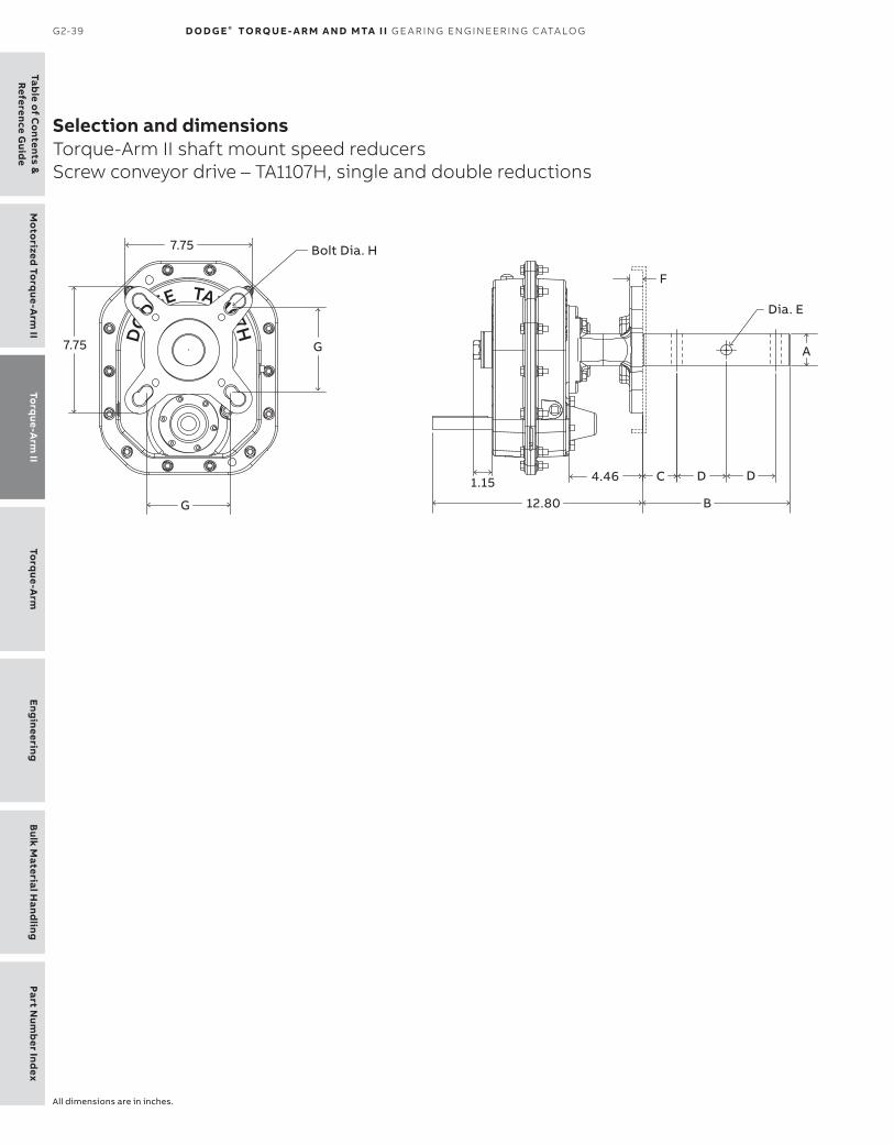
Table o
f Co
ntents &R
eference Guid
eTo
rque-A
rm II
Mo
torized To
rque-A
rm II
Torq
ue-Arm
Eng
ineeringB
ulk Material H
andling
Part Num
ber Ind
ex
G2-39 D O D G E ® TO RQ U E - A R M A N D MTA I I G E A R I N G EN G I N EER I N G C ATA LO G
Selection and dimensionsTorque-Arm II shaft mount speed reducersScrew conveyor drive – TA1107H, single and double reductions
Screw conveyor drive reducers and accessories
All dimensions are in inches.

Part
Num
ber
Ind
exEn
gin
eeri
ngB
ulk
Mat
eria
l Han
dlin
gTo
rque
-Arm
To
rque
-Arm
IIM
oto
rize
d To
rque
-Arm
IITa
ble
of
Co
nten
ts &
Ref
eren
ce G
uid
e
TO R Q U E- A R M I I G2-40
Selection and dimensionsTorque-Arm II shaft mount speed reducersScrew conveyor drive – TA1107H, single and double reductions
(1) Pos “C” Belt guard most popular for screw conveyor drive applications(2) SCA Adapter & hardware kit includes adapter, mounting wedge, keeper plate, key, seals and hardware(3) SCP Adjustable packing kit consists of flange, mounting hardware and braided packing seals(4) SCS Drive shaft is a shaft only. Hardware is stocked with the adapter & hardware kit.(5) A complete TA II screw conveyor drive, order a TA II reducer, SCA adapter & hardware kit, and SCS drive shaft.
The SCP adjustable packing kit is an optional accessory.
TA1107H Accessories for screw conveyor drives (1) (4) (5)
Description Part number Weight lbs.TA1107SCA Adapter & hardware kit (2) 901070 15.2
TA1107SCP Adjustable packing kit (3) 901071 0.8
TA1107SCS x 1-1/2 Drive shaft 901072 10.3
TA1107SCS x 2 Drive shaft 901073 13.5
TA1107SCS x 2-7/16 Drive shaft 901074 18.1
TA1107SCS x 3 Drive shaft 901075 24.4
TA1107SCS x 1-1/2 Stainless steel drive shaft 901080 10.3
TA1107SCS x 2 Stainless steel drive shaft 901081 13.5
TA1107SCS x 2-7/16 Stainless steel drive shaft 901082 18.1
TA1107SCS x 3 Stainless steel drive shaft 901083 24.4
TA1107MM Motor mount assembly (56-254T) 901090 39.5
TA1107BG Belt guard - Pos. C (56-254T) (1) 901097 47.2
TA0-TA3 Hydra-Lock dessicant breather Kit HLO 964372 2.0
XT Enclosed breather system, TA0-9 240050 2.0
ABB ability sensor 750000 0.5
TA1107H Screw conveyor drive dimensions
Screwdiameter
Drive Dimensionsshaft
B C D Hole
F GBolt
Dia A Dia E Dia H6, 9 1-1/2 9.00 2.13 3.00 17/32 0.75 4.00 1/2
9, 12 2 9.00 2.13 3.00 21/32 0.75 5.13 5/8
12, 14 2-7/16 9.69 2.75 3.00 21/32 0.75 5.63 5/8
12, 14, 16, 18, 20 3 9.88 2.88 3.00 25/32 0.75 6.00 3/4

Table o
f Co
ntents &R
eference Guid
eTo
rque-A
rm II
Mo
torized To
rque-A
rm II
Torq
ue-Arm
Eng
ineeringB
ulk Material H
andling
Part Num
ber Ind
ex
G2-41 D O D G E ® TO RQ U E - A R M A N D MTA I I G E A R I N G EN G I N EER I N G C ATA LO G
Selection and dimensionsTorque-Arm II shaft mount speed reducersMotor mount dimensions – TA1107H, position B & D
Motor mount dimensions
All dimensions are in inches.

Part
Num
ber
Ind
exEn
gin
eeri
ngB
ulk
Mat
eria
l Han
dlin
gTo
rque
-Arm
To
rque
-Arm
IIM
oto
rize
d To
rque
-Arm
IITa
ble
of
Co
nten
ts &
Ref
eren
ce G
uid
e
TO R Q U E- A R M I I G2-42
Selection and dimensionsTorque-Arm II shaft mount speed reducersMotor mount dimensions – TA1107H, position B & D (1)
Notes:Minimum centers contains 0.5” to allow for belt assembly(1) Motor Mount will fit NEMA and IEC frame motors; however motor mount hardware are inch dimensions.(2) M1, M2, M3 go through output shaft centerline
MountingLateral adjustment
Motor Motor framemount 56 143T & 145Theight
ACenters
ACenters
B Min B Max C Min C Max (2) Min Max Min Max
Position B -0.09 3.33 2.10 5.48
M1
0.78
17.7 22.0
1.22
17.7 22.0
M2 20.3 24.6 20.3 24.6
M3 22.9 27.2 22.9 27.2
Position D -0.09 3.33 2.10 5.48
M1
0.78
11.3 15.7
1.22
11.3 15.7
M2 13.9 18.2 13.9 18.2
M3 16.5 20.8 16.5 20.8
Mounting
Motor Motor framemount 182T & 184T 213T & 215T 254Theight
ACenters
ACenters
ACenters
(2) Min Max Min Max Min Max
Position B
M1
1.37
18.7 23.0
1.55
19.5 23.8
1.56
20.5 24.8
M2 21.3 25.6 22.1 26.4 23.1 27.4
M3 23.9 28.2 24.6 29.0 25.6 30.0
Position D
M1
1.37
12.3 16.7
1.55
13.1 17.4
1.56
14.1 18.4
M2 14.9 19.2 15.7 20.0 16.7 21.0
M3 17.5 21.8 18.3 22.6 19.3 23.6

Table o
f Co
ntents &R
eference Guid
eTo
rque-A
rm II
Mo
torized To
rque-A
rm II
Torq
ue-Arm
Eng
ineeringB
ulk Material H
andling
Part Num
ber Ind
ex
G2-43 D O D G E ® TO RQ U E - A R M A N D MTA I I G E A R I N G EN G I N EER I N G C ATA LO G
Selection and dimensionsTorque-Arm II shaft mount speed reducersMotor mount dimensions – TA1107H, position A & C
All dimensions are in inches.

Part
Num
ber
Ind
exEn
gin
eeri
ngB
ulk
Mat
eria
l Han
dlin
gTo
rque
-Arm
To
rque
-Arm
IIM
oto
rize
d To
rque
-Arm
IITa
ble
of
Co
nten
ts &
Ref
eren
ce G
uid
e
TO R Q U E- A R M I I G2-44
Selection and dimensionsTorque-Arm II shaft mount speed reducersMotor mount dimensions – TA1107H, position A & C(1) (3)
Notes:Minimum centers contains 0.5” to allow for belt assembly(1) Motor Mount will fit NEMA and IEC frame motors; however, motor mount hardware are inch dimensions.(2) M1, M2, M3, M4 go through output shaft centerline(3) See Table A, below, for minimum “M” mounting position required for specific screw diameter and reducer size
MountingLateral adjustment
Motor Motor framemount 56 143T & 145Theight
ACenters
ACenters
B Min B Max C Min C Max (2) Min Max Min Max
Position A -0.09 3.33 3.01 6.43
M1
0.78
13.8 17.9
1.22
13.8 17.9
M2 16.2 20.5 16.2 20.5
M3 18.8 23.0 18.8 23.0
M4 21.3 25.6 21.3 25.6
Position C -0.09 3.33 3.01 6.43
M1
0.78
13.8 17.9
1.22
13.8 17.9
M2 16.2 20.5 16.2 20.5
M3 18.8 23.0 18.8 23.0
M4 21.3 25.6 21.3 25.6
Table A – Screw conveyor motor mount minimum “M” mounting positions (1)
NominalscrewDia
Troughheight
Dim
Minimum mounting position
TA0107L TA1107H TA2115H TA3203H TA4207H TA5215H TA6307H TA7315H
6 7.00 M2 M3 M2 M2 M2 M1 M1 M1
9 9.00 M3 M4 M3 M3 M2 M2 M2 M1
12 10.00 M4 M4 M3 M3 M2 M2 M2 M1
14 11.00 M4 M4 M4 M3 M3 M2 M2 M2
16 11.50 M4 M4 M4 M4 M3 M2 M2 M2
18 12.13 – – M4 M4 M3 M3 M2 M2
20 13.50 – – M4 M4 M3 M3 M3 M2
24 16.50 – – – – M4 M3 M3 M3
Mounting
Motor Motor framemount 182T & 184T 213T & 215T 254Theight
ACenters
ACenters
ACenters
(2) Min Max Min Max Min Max
Position A
M1
1.37
14.7 18.9
1.55
15.4 19.6
1.56
16.4 20.6
M2 17.2 21.4 17.9 22.2 18.9 23.2
M3 19.7 24.0 20.5 24.7 21.5 25.7
M4 22.3 26.6 23.0 27.3 24.0 28.3
Position C
M1
1.37
14.7 18.9
1.55
15.4 19.6
1.56
16.4 20.6
M2 17.2 21.4 17.9 22.2 18.9 23.2
M3 19.7 24.0 20.5 24.7 21.5 25.7
M4 22.3 26.6 23.0 27.3 24.0 28.3
Note:(1) For U or flared trough ends per CEMA 300-014
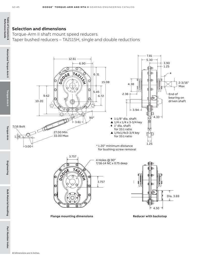
Table o
f Co
ntents &R
eference Guid
eTo
rque-A
rm II
Mo
torized To
rque-A
rm II
Torq
ue-Arm
Eng
ineeringB
ulk Material H
andling
Part Num
ber Ind
ex
G2-45 D O D G E ® TO RQ U E - A R M A N D MTA I I G E A R I N G EN G I N EER I N G C ATA LO G
Selection and dimensionsTorque-Arm II shaft mount speed reducersTaper bushed reducers – TA2115H, single and double reductions
TA2115H Taper bushed reducers and accessories
All dimensions are in inches.

Part
Num
ber
Ind
exEn
gin
eeri
ngB
ulk
Mat
eria
l Han
dlin
gTo
rque
-Arm
To
rque
-Arm
IIM
oto
rize
d To
rque
-Arm
IITa
ble
of
Co
nten
ts &
Ref
eren
ce G
uid
e
TO R Q U E- A R M I I G2-46
Selection and dimensionsTorque-Arm II shaft mount speed reducersTaper bushed reducers – TA2115H, single and double reductions
TA2115H Taper Bushed Reducers (1) TA2115H AccessoriesReducersize
Part number
AGMAcode
Actualratio
Weightlbs. Description Part
numberWeight
lbs.
TA2115H05 902004 115S05 5.20 84.2 TA2115RA Rod assembly (1) + 902109 6.9
TA2115H09 902003 115D09 9.10 86.5 TA2115BS Backstop assembly (2) 902102 3.9
TA2115H15 902002 115D15 15.62 86.3 TA2115MM Motor mount assembly (56-256T) (3) 902090 52.6
TA2115H25 902001 115D25 25.07 86.1 TA2115BG Belt guard - Pos. B (56-256T) 902096 47.7
TA2115H33 902000 115D33 33.33 85.7 TA0107, 1107, 2115 Belt guard assembly – Pos. B, M2 900101 37.0
TA2115BG Belt guard - Pos. C (56-256T) (4) 902097 52.1
TA2115BG Belt guard - Pos. D (56-256T) 902099 51.0
TA0-TA3 Hydra-Lock dessicant breather kit HL0 964372 2.0
XT Enclosed breather system, TA0-9 240050 2.0
TA0-TA3 Vertical breather kit 900112 2.0
TA2115H V-Ring kit 902249 0.2
TA2115H Lube kit LUBEKITTA2115 8.1
ABB ability sensor 750000 0.5
(1) Reducers are supplied from stock ready for vertical mounting and for flange mounting. Rod assembly is not included with reducer, must order as a separate part number.
+ Rod assembly mounting locations are limited to positions show in drawing.
(2) See page G2-127 for input shaft speed necessary for backstop sprag lift-off(3) Motor Mount will fit NEMA and IEC frame motors; however, motor mount
hardware are inch dimensions.(4) Use Position-C belt guard for TA II reducer in screw conveyor drive applications
▲ AGMA maximum bore size (5) Bushing kit required to mount TA II reducer to driven shaft (6) Bushing kit is not required to mount TA II reducer on screw conveyor drive shaft in a screw conveyor application (7) Standard shaft bushing kit includes two standard bushings with back-up plates and snap rings; hardware, and key. (8) Short shaft bushing kit includes one standard bushing, one long bushing with insertable wedge; two back-up plates with snap rings; hardware and key. This is an optional bushing for after market, short shaft mounting. (9) Minimum keyseat and shaft length required to mount reducer with bushing kit (10) Always check the driven shaft and key for strength
Closed bushing covers may not be compatible with belt guards or large sheave installationsSplit bushing covers are designed for use on “driven machine” side of reducer with shaft through(12) ABS Polymer covers are designed with bolts for tapped reducers, non tapped reducers will require self tapping screws and customer modification of
reducer
TA2115H Tapered Bushing Kits (5) (6)
Bushing size
Partnumber
Weightlbs.
Shaft keyseat
Bushing sizePart
numberWeight
lbs.
Shaft Standard Short shaft keyseatshaft required bushing kit requiredbushing kit (7) (9) (10) (8) (9) (10)TA2115TB x 2-3/16 902020 4.7 1/2 x 1/4 x 7.80 – – – –
TA2115TB x 2 902022 5.2 1/2 x 1/4 x 7.80 – – – –
TA2115TB x 1-15/16 ▲ 902023 5.4 1/2 x 1/4 x 7.80 TA2115TBS x 1-15/16 902030 5.6 1/2 x 1/4 x 4.80
TA2115TB x 1-7/8 902024 5.6 1/2 x 1/4 x 7.80 TA2115TBS x 1-7/8 902031 5.9 1/2 x 1/4 x 4.80
TA2115TB x 1-3/4 902025 5.8 3/8 x 3/16 x 7.80 TA2115TBS x 1-3/4 902032 6 3/8 x 3/16 x 4.80
TA2115TB x 1-11/16 902026 6.1 3/8 x 3/16 x 7.80 TA2115TBS x 1-11/16 902033 6.6 3/8 x 3/16 x 4.80
TA2115TB x 1-5/8 902027 6.0 3/8 x 3/16 x 7.80 TA2115TBS x 1-5/8 902034 6.8 3/8 x 3/16 x 4.80
TA2115TB x 1-1/2 902028 6.4 3/8 x 3/16 x 7.80 TA2115TBS x 1-1/2 902035 7.3 3/8 x 3/16 x 4.80
TA2115TB x 1-7/16 902029 6.4 3/8 x 3/16 x 7.80 TA2115TBS x 1-7/16 902036 7.4 3/8 x 3/16 x 4.80
TA2115TB x 1-3/8 902060 6.5 5/16 x 5/32 x 7.80 TA2115TBS x 1-3/8 902037 7.6 5/16 x 5/32 x 4.80
TA2115TB x 1-5/16 902061 6.7 5/16 x 5/32 x 7.80 TA2115TBS x 1-5/16 902038 7.8 5/16 x 5/32 x 4.80
Bushing covers
Reducer size Description Part number Weight
TA2115H ABS Polymer closed (12) 902142 0.6
TA2115H ABS Polymer split (12) 902143 0.5

Table o
f Co
ntents &R
eference Guid
eTo
rque-A
rm II
Mo
torized To
rque-A
rm II
Torq
ue-Arm
Eng
ineeringB
ulk Material H
andling
Part Num
ber Ind
ex
G2-47 D O D G E ® TO RQ U E - A R M A N D MTA I I G E A R I N G EN G I N EER I N G C ATA LO G
Selection and dimensionsTorque-Arm II shaft mount speed reducersScrew conveyor drive – TA2115H, single and double reductions
Screw conveyor drive reducers and accessories
All dimensions are in inches.

Part
Num
ber
Ind
exEn
gin
eeri
ngB
ulk
Mat
eria
l Han
dlin
gTo
rque
-Arm
To
rque
-Arm
IIM
oto
rize
d To
rque
-Arm
IITa
ble
of
Co
nten
ts &
Ref
eren
ce G
uid
e
TO R Q U E- A R M I I G2-48
Selection and dimensionsTorque-Arm II shaft mount speed reducersScrew conveyor drive – TA2115H, single and double reductions
(1) Pos “C” Belt guard most popularfor screw conveyor drive applications(2) SCA Adapter & hardware kit includes adapter, mounting wedge, keeper plate, key, seals and hardware(3) SCP Adjustable packing kit consists of flange, mounting hardware and braided packing seals(4) SCS Drive shaft is a shaft only. Hardware is stocked with the adapter & hardware kit.(5) A complete TA II screw conveyor drive, order a TA II reducer, SCA adapter & hardware kit, and SCS drive shaft.
The SCP adjustable packing kit is an optional accessory.
TA2115H Accessories for screw conveyor drives (1) (4) (5)
Description Part number Weight lbs.TA2115SCA Adapter & hardware kit (2) 902070 19.2
TA2115SCP Adjustable packing kit (3) 902071 1.2
TA2115SCS x 1-1/2 Drive shaft 902072 15.4
TA2115SCS x 2 Drive shaft 902073 18.6
TA2115SCS x 2-7/16 Drive shaft 902074 23.3
TA2115SCS x 3 Drive shaft 902075 29.5
TA2115SCS x 1-1/2 Stainless steel drive shaft 902080 15.4
TA2115SCS x 2 Stainless Steel drive shaft 902081 18.6
TA2115SCS x 2-7/16 Stainless steel drive shaft 902082 23.3
TA2115SCS x 3 Stainless steel drive shaft 902083 29.5
TA2115MM Motor mount assembly (56-256T) 902090 56.5
TA2115BG Belt guard - Pos. C (56-256T) (1) 902097 47.7
TA0-TA3 Hydra-Lock dessicant breather Kit HLO 964372 2.0
XT Enclosed breather system, TA0-9 240050 2.0
ABB ability sensor 750000 0.5
TA2115H Screw conveyor drive dimensions
Screwdiameter
Drive Dimensionsshaft
B C D Hole
F GBolt
Dia A Dia E Dia H
6, 9 1-1/2 9.00 2.13 3.00 17/32 0.75 4.00 1/2
9, 12 2 9.00 2.13 3.00 21/32 0.75 5.13 5/8
12, 14 2-7/16 9.69 2.75 3.00 21/32 0.75 5.63 5/8
12, 14, 16, 18, 20 3 9.88 2.88 3.00 25/32 0.75 6.00 3/4

Table o
f Co
ntents &R
eference Guid
eTo
rque-A
rm II
Mo
torized To
rque-A
rm II
Torq
ue-Arm
Eng
ineeringB
ulk Material H
andling
Part Num
ber Ind
ex
G2-49 D O D G E ® TO RQ U E - A R M A N D MTA I I G E A R I N G EN G I N EER I N G C ATA LO G
Selection and dimensionsTorque-Arm II shaft mount speed reducersMotor mount dimensions – TA2115H, position B & D
Motor mount dimensions
All dimensions are in inches.

Part
Num
ber
Ind
exEn
gin
eeri
ngB
ulk
Mat
eria
l Han
dlin
gTo
rque
-Arm
To
rque
-Arm
IIM
oto
rize
d To
rque
-Arm
IITa
ble
of
Co
nten
ts &
Ref
eren
ce G
uid
e
TO R Q U E- A R M I I G2-50
Notes:Minimum centers contains 0.5” to allow for belt assembly(1) Motor Mount will fit NEMA and IEC frame motors; however, motor mount hardware are inch dimensions.(2) M1, M2, M3 go through output shaft centerline
MountingLateral adjustment
Motor Motor framemount 56 143T & 145Theight
ACenters
ACenters
B Min B Max C Min C Max (2) Min Max Min Max
Position B 0.19 3.61 2.32 5.74
M1
0.78
18.5 22.2
1.22
18.5 22.2
M2 21.6 25.3 21.6 25.3
M3 24.6 28.3 24.6 28.3
Position D 0.19 3.61 2.32 5.74
M1
0.78
10.4 14.1
1.22
10.4 14.1
M2 13.5 17.2 13.5 17.2
M3 16.6 20.3 16.6 20.3
Mounting
Motor Motor framemount 182T & 184T 213T & 215T 254T & 256Theight
ACenters
ACenters
ACenters
(2) Min Max Min Max Min Max
Position B
M1
1.37
19.5 23.2
1.55
20.3 24.0
1.56
21.3 25.0
M2 22.6 26.3 23.3 27.0 24.3 28.0
M3 25.6 29.3 26.4 30.1 27.4 31.1
Position D
M1
1.37
11.4 15.1
1.55
12.2 15.9
1.56
13.2 16.9
M2 14.5 18.2 15.3 19.0 16.3 20.0
M3 17.6 21.3 18.3 22.0 19.3 23.0
Selection and dimensionsTorque-Arm II shaft mount speed reducersMotor mount dimensions – TA2115H, position B & D (1)

Table o
f Co
ntents &R
eference Guid
eTo
rque-A
rm II
Mo
torized To
rque-A
rm II
Torq
ue-Arm
Eng
ineeringB
ulk Material H
andling
Part Num
ber Ind
ex
G2-51 D O D G E ® TO RQ U E - A R M A N D MTA I I G E A R I N G EN G I N EER I N G C ATA LO G
Selection and dimensionsTorque-Arm II shaft mount speed reducersMotor mount dimensions – TA2115H, position A & C
All dimensions are in inches.

Part
Num
ber
Ind
exEn
gin
eeri
ngB
ulk
Mat
eria
l Han
dlin
gTo
rque
-Arm
To
rque
-Arm
IIM
oto
rize
d To
rque
-Arm
IITa
ble
of
Co
nten
ts &
Ref
eren
ce G
uid
e
TO R Q U E- A R M I I G2-52
Notes:Minimum centers contains 0.5” to allow for belt assembly(1) Motor Mount will fit NEMA and IEC frame motors; however, motor mount hardware are inch dimensions.(2) M1, M2, M3, M4 go through output shaft centerline(3) See Table A, below, for minimum “M” mounting position required for specific screw diameter and reducer size
MountingLateral adjustment
Motor Motor framemount 56 143T & 145Theight
ACenters
ACenters
B Min B Max C Min C Max (2) Min Max Min Max
Position A 0.19 3.61 3.39 6.81
M1
0.78
13.6 17.2
1.22
13.6 17.2
M2 16.6 20.1 16.6 20.1
M3 19.5 23.1 19.5 23.1
M4 22.5 26.2 22.5 26.2
Position C 0.19 3.61 3.39 6.81
M1
0.78
13.6 17.2
1.22
13.6 17.2
M2 16.6 20.1 16.6 20.1
M3 19.5 23.1 19.5 23.1
M4 22.5 26.2 22.5 26.2
Table A – Screw conveyor motor mount minimum “M” mounting positions (1)
NominalscrewDia
Troughheight
Dim
Minimum mounting position
TA0107L TA1107H TA2115H TA3203H TA4207H TA5215H TA6307H TA7315H
6 7.00 M2 M3 M2 M2 M2 M1 M1 M1
9 9.00 M3 M4 M3 M3 M2 M2 M2 M1
12 10.00 M4 M4 M3 M3 M2 M2 M2 M1
14 11.00 M4 M4 M4 M3 M3 M2 M2 M2
16 11.50 M4 M4 M4 M4 M3 M2 M2 M2
18 12.13 – – M4 M4 M3 M3 M2 M2
20 13.50 – – M4 M4 M3 M3 M3 M2
24 16.50 – – – – M4 M3 M3 M3
Mounting
Motor Motor framemount 182T & 184T 213T & 215T 254T & 256Theight
ACenters
ACenters
ACenters
(2) Min Max Min Max Min Max
Position A
M1
1.37
14.6 18.1
1.55
15.3 18.9
1.56
16.3 19.8
M2 17.5 21.1 18.3 21.9 19.2 22.8
M3 20.5 24.1 21.2 24.9 22.2 25.9
M4 23.5 27.1 24.2 27.9 25.2 28.9
Position C
M1
1.37
14.6 18.1
1.55
15.3 18.9
1.56
16.3 19.8
M2 17.5 21.1 18.3 21.9 19.2 22.8
M3 20.5 24.1 21.2 24.9 22.2 25.9
M4 23.5 27.1 24.2 27.9 25.2 28.9
Note:(1) For U or flared trough ends per CEMA 300-014
Selection and dimensionsTorque-Arm II shaft mount speed reducersMotor mount dimensions – TA2115H, position A & C(1) (3)

Table o
f Co
ntents &R
eference Guid
eTo
rque-A
rm II
Mo
torized To
rque-A
rm II
Torq
ue-Arm
Eng
ineeringB
ulk Material H
andling
Part Num
ber Ind
ex
G2-53 D O D G E ® TO RQ U E - A R M A N D MTA I I G E A R I N G EN G I N EER I N G C ATA LO G
Selection and dimensionsTorque-Arm II shaft mount speed reducersTaper bushed reducers – TA3203H, single and double reductions
TA3203H Taper bushed reducers and accessories
All dimensions are in inches.

Part
Num
ber
Ind
exEn
gin
eeri
ngB
ulk
Mat
eria
l Han
dlin
gTo
rque
-Arm
To
rque
-Arm
IIM
oto
rize
d To
rque
-Arm
IITa
ble
of
Co
nten
ts &
Ref
eren
ce G
uid
e
TO R Q U E- A R M I I G2-54
Selection and dimensionsTorque-Arm II shaft mount speed reducersTaper bushed reducers – TA3203H, single and double reductions
TA3203H Taper bushed reducers (1) ■ TA3203H AccessoriesReducersize
Part number
AGMAcode
Actualratio
Weightlbs. Description Part
numberWeight
lbs.
TA2115H05 902004 115S05 5.20 84.2 TA3203RA Rod assembly (1) + 903109 6.9
TA2115H09 902003 115D09 9.10 86.5 TA3203BS Backstop assembly (2) 903102 4.7
TA2115H15 902002 115D15 15.62 86.3 TA3203MM Motor mount assembly (143-286T) (3) 903090 86.7
TA2115H25 902001 115D25 25.07 86.1 TA3203BG Belt guard - Pos. B (143-286T) 903096 65.5
TA2115H33 902000 115D33 33.33 85.7 TA3203 Belt guard assembly – Pos. B, M2 903101 55.0
TA3203BG Belt guard - Pos. C (143-286T) (4) 903097 67.9
TA3203BG Belt guard - Pos. D (143-286T) 903099 67.0
TA0-TA3 Hydra-Lock dessicant breather kit HL0 964372 2.0
XT Enclosed breather system, TA0-9 240050 2.0
TA0-TA3 Vertical breather kit 900112 2.0
TA3203H V-Ring kit 903249 0.2
TA3203H Lube kit LUBEKITTA3203 10.4
ABB ability sensor 750000 0.5
(1) Reducers are supplied from stock ready for vertical mounting and for flange mounting. Rod assembly is not included with reducer, must order as a separate part number.
■ See page G2-121 for maximum bore straight bore TA II reducers+ Rod assembly mounting locations are limited to positions show
in drawing.
(2) See page G2-127 for input shaft speed necessary for backstop sprag lift-off(3) Motor Mount will fit NEMA and IEC frame motors; however, motor mount
hardware are inch dimensions.(4) Use Position-C belt guard for TA II reducer in screw conveyor drive applications
▲ AGMA maximum bore size (5) Bushing kit required to mount TA II reducer to driven shaft (6) Bushing kit is not required to mount TA II reducer on screw conveyor drive shaft in a screw conveyor application (7) Standard shaft bushing kit includes two standard bushings with back-up plates and snap rings; hardware, and key. (8) Short shaft bushing kit includes one standard bushing, one long bushing with insertable wedge; two back-up plates with snap rings; hardware and key. This is an optional bushing for after market, short shaft mounting. (9) Minimum keyseat and shaft length required to mount reducer with bushing kit (10) Always check the driven shaft and key for strength
Closed bushing covers may not be compatible with belt guards or large sheave installationsSplit bushing covers are designed for use on “driven machine” side of reducer with shaft through(12) ABS Polymer covers are designed with bolts for tapped reducers, non tapped reducers will require self tapping screws and customer modification of
reducer
TA3203H Tapered bushing kits (5) (6)
Bushing size
Partnumber
Weightlbs.
Shaft keyseat
Bushing sizePart
numberWeight
lbs.
Shaft Standard Short shaft keyseatshaft required bushing kit requiredbushing kit (7) (9) (10) (8) (9) (10)TA3203TB x 2-3/8 903020 6.1 5/8 x 5/16 x 8.55 – – – –
TA3203TB x 2-1/4 903021 6.2 1/2 x 1/4 x 8.55 – – – –TA3203TB x 2-3/16 ▲ 903022 6.8 1/2 x 1/4 x 8.55 TA3203TBS x 2-3/16 903030 7.0 1/2 x 1/4 x 5.46TA3203TB x 2-1/8 903023 7.0 1/2 x 1/4 x 8.55 TA3203TBS x 2-1/8 903031 7.4 1/2 x 1/4 x 5.46TA3203TB x 2 903024 7.5 1/2 x 1/4 x 8.55 TA3203TBS x 2 903032 8.0 1/2 x 1/4 x 5.46TA3203TB x 1-15/16 903025 7.8 1/2 x 1/4 x 8.55 TA3203TBS x 1-15/16 903033 8.4 1/2 x 1/4 x 5.46TA3203TB x 1-7/8 903026 8.0 1/2 x 1/4 x 8.55 TA3203TBS x 1-7/8 903034 8.7 1/2 x 1/4 x 5.46TA3203TB x 1-3/4 903027 8.0 3/8 x 3/16 x 8.55 TA3203TBS x 1-3/4 903035 9.0 3/8 x 3/16 x 5.46TA3203TB x 1-11/16 903028 8.2 3/8 x 3/16 x 8.55 TA3203TBS x 1-11/16 903036 9.3 3/8 x 3/16 x 5.46TA3203TB x 1-5/8 903029 8.4 3/8 x 3/16 x 8.55 TA3023TBS x 1-5/8 903037 9.6 3/8 x 3/16 x 5.46TA3203TB x 1-1/2 903060 8.8 3/8 x 3/16 x 8.55 TA3203TBS x 1-1/2 903038 9.9 3/8 x 3/16 x 5.46TA3203TB x 1-7/16 903061 8.8 3/8 x 3/16 x 8.55 TA3203TBS x 1-7/16 903039 10.0 3/8 x 3/16 x 5.46
Bushing covers
Reducer size Description Part number Weight
TA2115H ABS Polymer closed (12) 902142 0.6
TA2115H ABS Polymer split (12) 902143 0.5

Table o
f Co
ntents &R
eference Guid
eTo
rque-A
rm II
Mo
torized To
rque-A
rm II
Torq
ue-Arm
Eng
ineeringB
ulk Material H
andling
Part Num
ber Ind
ex
G2-55 D O D G E ® TO RQ U E - A R M A N D MTA I I G E A R I N G EN G I N EER I N G C ATA LO G
Selection and dimensionsTorque-Arm II shaft mount speed reducersScrew conveyor drive – TA3203H, single and double reductions
Screw conveyor drive reducers and accessories
All dimensions are in inches.

Part
Num
ber
Ind
exEn
gin
eeri
ngB
ulk
Mat
eria
l Han
dlin
gTo
rque
-Arm
To
rque
-Arm
IIM
oto
rize
d To
rque
-Arm
IITa
ble
of
Co
nten
ts &
Ref
eren
ce G
uid
e
TO R Q U E- A R M I I G2-56
Selection and dimensionsTorque-Arm II shaft mount speed reducersScrew conveyor drive – TA3203H, single and double reductions
(1) Pos “C” Belt guard most popular for screw conveyor drive applications(2) SCA Adapter & hardware kit includes adapter, mounting wedge, keeper plate, key, seals and hardware(3) SCP Adjustable packing kit consists of flange, mounting hardware and braided packing seals(4) SCS Drive shaft is a shaft only. Hardware is stocked with the adapter & hardware kit.(5) A complete TA II screw conveyor drive, order a TA II reducer, SCA adapter & hardware kit, and SCS drive shaft.
The SCP adjustable packing kit is an optional accessory.
TA3203H Accessories for screw conveyor drives (1) (4) (5)
Description Part number Weight lbs.TA3203SCA Adapter & hardware kit (2) 903070 22.0
TA3203SCP Adjustable packing kit (3) 903071 1.4
TA3203SCS x 1-1/2 Drive shaft 903072 19.3
TA3203SCS x 2 Drive shaft 903073 22.6
TA3203SCS x 2-7/16 Drive shaft 903074 27.2
TA3203SCS x 3 Drive shaft 903075 33.6
TA3203SCS x 3-7/16 Drive shaft 903076 44.8
TA3203SCS x 1-1/2 Stainless Steel drive shaft 903080 19.3
TA3203SCS x 2 Stainless Steel drive shaft 903081 22.6
TA3203SCS x 2-7/16 Stainless steel drive shaft 903082 27.2
TA3203SCS x 3 Stainless Steel drive shaft 903083 33.6
TA3203SCS x 3-7/16 Stainless steel drive shaft 903084 44.8
TA3203MM Motor mount assembly (56-286T) 902090 86.7
TA3203BG Belt guard - Pos. C (56-286T) (1) 902097 67.9
TA0-TA3 Hydra-Lock dessicant breather Kit HLO 964372 2.0
XT Enclosed breather system, TA0-9 240050 2.0
ABB ability sensor 750000 0.5
TA3203H Screw conveyor drive dimensions
Screwdiameter
Drive Dimensionsshaft
B C D Hole
F GBolt
Dia A Dia E Dia H
6, 9 1-1/2 9.00 2.13 3.00 17/32 0.75 4.00 1/2
9, 12 2 9.00 2.13 3.00 21/32 0.75 5.13 5/8
12, 14 2-7/16 9.69 2.75 3.00 21/32 0.75 5.63 5/8
12, 14, 16, 18, 20 3 9.88 2.88 3.00 25/32 0.75 6.00 3/4
18, 20, 24 3-7/16 13.13 3.88 4.00 29/32 .75 6.75 7/8

Table o
f Co
ntents &R
eference Guid
eTo
rque-A
rm II
Mo
torized To
rque-A
rm II
Torq
ue-Arm
Eng
ineeringB
ulk Material H
andling
Part Num
ber Ind
ex
G2-57 D O D G E ® TO RQ U E - A R M A N D MTA I I G E A R I N G EN G I N EER I N G C ATA LO G
Selection and dimensionsTorque-Arm II shaft mount speed reducersMotor mount dimensions – TA3203H, position B & D
Motor mount dimensions
All dimensions are in inches.

Part
Num
ber
Ind
exEn
gin
eeri
ngB
ulk
Mat
eria
l Han
dlin
gTo
rque
-Arm
To
rque
-Arm
IIM
oto
rize
d To
rque
-Arm
IITa
ble
of
Co
nten
ts &
Ref
eren
ce G
uid
e
TO R Q U E- A R M I I G2-58
Selection and dimensionsTorque-Arm II shaft mount speed reducersMotor mount dimensions – TA3203H, position B & D (1)
Notes:Minimum centers contains 0.5” to allow for belt assembly(1) Motor Mount will fit NEMA and IEC frame motors; however, motor mount hardware are inch dimensions.(2) M1, M2, M3, M4 go through output shaft centerline
MountingLateral adjustment
Motor Motor framemount 143T & 145T 182T & 184Theight
ACenters
ACenters
B Min B Max C Min C Max (2) Min Max Min Max
Position A 0.04 5.34 2.06 7.36
M1
1.22
19.8 23.9
1.37
20.8 24.9
M2 23.3 27.3 24.3 28.3
M3 26.7 30.8 27.7 31.8
Position C 0.04 5.34 2.06 7.36
M1
1.22
10.2 14.2
1.37
11.2 15.2
M2 13.6 17.7 14.6 18.7
M3 17.1 21.1 18.1 22.1
Mounting
Motor Motor framemount 213T & 215T 254T & 256T 284T & 286Theight
ACenters
ACenters
ACenters
(2) Min Max Min Max Min Max
Position A
M1
1.55
21.6 25.6
1.56
22.6 26.6
1.16
23.3 27.4
M2 25.0 29.1 26.0 30.1 26.8 30.8
M3 28.5 32.5 29.5 33.5 30.2 34.3
Position C
M1
1.55
11.9 16.0
1.56
12.9 17.0
1.16
13.7 17.7
M2 15.4 19.4 16.4 20.4 17.1 21.2
M3 18.8 22.9 19.8 23.9 20.6 24.6

Table o
f Co
ntents &R
eference Guid
eTo
rque-A
rm II
Mo
torized To
rque-A
rm II
Torq
ue-Arm
Eng
ineeringB
ulk Material H
andling
Part Num
ber Ind
ex
G2-59 D O D G E ® TO RQ U E - A R M A N D MTA I I G E A R I N G EN G I N EER I N G C ATA LO G
Selection and dimensionsTorque-Arm II shaft mount speed reducersMotor mount dimensions – TA3203H, position A & C
All dimensions are in inches.

Part
Num
ber
Ind
exEn
gin
eeri
ngB
ulk
Mat
eria
l Han
dlin
gTo
rque
-Arm
To
rque
-Arm
IIM
oto
rize
d To
rque
-Arm
IITa
ble
of
Co
nten
ts &
Ref
eren
ce G
uid
e
TO R Q U E- A R M I I G2-60
Notes:Minimum centers contains 0.5” to allow for belt assembly(1) Motor Mount will fit NEMA and IEC frame motors; however, motor mount hardware are inch dimensions.(2) M1, M2, M3, M4 go through output shaft centerline(3) See Table A, below, for minimum “M” mounting position required for specific screw diameter and reducer size
MountingLateral adjustment
Motor Motor framemount 143T & 145T 182T & 184Theight
ACenters
ACenters
B Min B Max C Min C Max (2) Min Max Min Max
Position A 0.04 5.34 3.07 8.37
M1
1.22
14.6 18.4
1.37
15.5 19.4
M2 17.9 21.8 18.9 22.8
M3 21.2 25.2 22.2 26.2
M4 24.6 28.6 25.6 29.6
Position C 0.04 5.34 3.07 8.37
M1
1.22
13.6 17.4
1.37
14.5 18.4
M2 16.9 20.8 17.8 21.7
M3 20.2 24.2 21.2 25.1
M4 23.6 27.6 24.6 28.5
Table A – Screw conveyor motor mount minimum “M” mounting positions (1)
NominalscrewDia
Troughheight
Dim
Minimum mounting position
TA0107L TA1107H TA2115H TA3203H TA4207H TA5215H TA6307H TA7315H
6 7.00 M2 M3 M2 M2 M2 M1 M1 M1
9 9.00 M3 M4 M3 M3 M2 M2 M2 M1
12 10.00 M4 M4 M3 M3 M2 M2 M2 M1
14 11.00 M4 M4 M4 M3 M3 M2 M2 M2
16 11.50 M4 M4 M4 M4 M3 M2 M2 M2
18 12.13 – – M4 M4 M3 M3 M2 M2
20 13.50 – – M4 M4 M3 M3 M3 M2
24 16.50 – – – – M4 M3 M3 M3
Mounting
Motor Motor framemount 213T & 215T 254T & 256T 284T & 286Theight
ACenters
ACenters
ACenters
(2) Min Max Min Max Min Max
Position A
M1
1.55
16.2 20.1
1.56
17.2 21.1
1.16
17.9 21.8
M2 19.6 23.5 20.5 24.5 21.3 25.2
M3 22.9 26.9 23.9 27.9 24.7 28.6
M4 26.3 30.3 27.3 31.3 28.1 32.1
Position C
M1
1.55
15.2 19.1
1.56
16.2 20.1
1.16
16.9 20.8
M2 18.6 22.5 19.5 23.5 20.2 24.2
M3 21.9 25.9 22.9 26.9 23.6 27.6
M4 25.3 29.3 26.3 30.3 27.0 31.0
Note:(1) For U or flared trough ends per CEMA 300-014
Selection and dimensionsTorque-Arm II shaft mount speed reducersMotor mount dimensions – TA3203H, position A & C(1) (3)

Table o
f Co
ntents &R
eference Guid
eTo
rque-A
rm II
Mo
torized To
rque-A
rm II
Torq
ue-Arm
Eng
ineeringB
ulk Material H
andling
Part Num
ber Ind
ex
G2-61 D O D G E ® TO RQ U E - A R M A N D MTA I I G E A R I N G EN G I N EER I N G C ATA LO G
Selection and dimensionsTorque-Arm II shaft mount speed reducersTaper bushed reducers – TA4207H, single and double reductions
TA4207H Taper bushed reducers and accessories
All dimensions are in inches.

Part
Num
ber
Ind
exEn
gin
eeri
ngB
ulk
Mat
eria
l Han
dlin
gTo
rque
-Arm
To
rque
-Arm
IIM
oto
rize
d To
rque
-Arm
IITa
ble
of
Co
nten
ts &
Ref
eren
ce G
uid
e
TO R Q U E- A R M I I G2-62
Selection and dimensionsTorque-Arm II shaft mount speed reducersTaper bushed reducers – TA4207H, single and double reductions
TA4207H Taper bushed reducers (1) ■ TA4207H AccessoriesReducersize
Part number
AGMAcode
Actualratio
Weightlbs. Description Part
numberWeight
lbs.
TA4207H05 904004 207S05 5.00 178.5 TA4207RA Rod Assembly (1) + 904109 10.6TA4207H09 904003 207D09 9.23 187.1 TA4207BS Backstop Assembly (5, 9, 15, 25:1) (2) 904102 5.2TA4207H15 904002 207D15 15.00 186.7 TA4207BS 40:1 Backstop Assembly (2) 904103 5.2TA4207H25 904001 207D25 25.13 186.0 TA4207MM Motor Mount Assembly (143-326T) (3) 904090 114.3TA4207H40 904000 207D40 39.11 185.4 TA4207BG Belt Guard - Pos. B (143-326T) 904096 79.6
TA4207 Belt guard assembly Pos. B M2 904101 64.0TA4207BG Belt Guard - Pos. C (143-326T) (4) 904097 82.7TA4207BG Belt Guard - Pos. D (143-326T) 904099 80.6TA4207CF Cooling Assembly ● 904106 2.0TA4-TA9 Hydra-Lock Dessicant Breather Kit HL1 964364 2.0XT Enclosed Breather System, TA0-9 240050 2.0TA4-TA12 Vertical Breather Kit 904112 2.0TA4207H V-Ring Kit 904249 0.3TA4207H Lube Kit LUBEKITTA4207 16.2ABB ability sensor 750000 0.5
(1) Reducers are supplied from stock ready for vertical mounting and for flange mounting. Rod assembly is not included with reducer, must order as a separate part number.
■ See page G2-121 for maximum bore straight bore TA II reducers+ Rod assembly mounting locations are limited to positions show
in drawing.
(2) See page G2-127 for input shaft speed necessary for backstop sprag lift-off(3) Motor Mount will fit NEMA and IEC frame motors; however, motor mount
hardware are inch dimensions.(4) Use Position-C belt guard for TA II reducer in screw conveyor drive applications
▲ AGMA maximum bore size (5) Bushing kit required to mount TA II reducer to driven shaft (6) Bushing kit is not required to mount TA II reducer on screw conveyor drive shaft in a screw conveyor application (7) Standard shaft bushing kit includes two standard bushings with back-up plates and snap rings; hardware, and key. (8) Short shaft bushing kit includes one standard bushing, one long bushing with insertable wedge; two back-up plates with snap rings; hardware and key. This is an optional bushing for after market, short shaft mounting. (9) Minimum keyseat and shaft length required to mount reducer with bushing kit (10) Always check the driven shaft and key for strength
Closed bushing covers may not be compatible with belt guards or large sheave installationsSplit bushing covers are designed for use on “driven machine” side of reducer with shaft through(12) ABS Polymer covers are designed with bolts for tapped reducers, non tapped reducers will require self tapping screws and customer modification of
reducer
TA4207H Tapered bushing kits (5) (6)
Bushing size
Partnumber
Weightlbs.
Shaft keyseat
Bushing size
Partnumber
Weightlbs.
Shaft Standard Short shaft keyseatshaft required bushing kit requiredbushing kit (7) (9) (10) (8) (9) (10)TA4207TB x 2-11/16 904020 9.4 5/8 x 5/16 x 8.93 – – – –TA4207TB x 2-1/2 904021 10.6 5/8 x 5/16 x 8.93 – – – –TA4207TB x 2-7/16 ▲ 904022 10.8 5/8 x 5/16 x 8.93 TA4207TBS x 2-7/16 904032 11.3 5/8 x 5/16 x 5.65TA4207TB x 2-3/8 904023 11.3 5/8 x 5/16 x 8.93 TA4207TBS x 2-3/8 904033 11.8 5/8 x 5/16 x 5.65TA4207TB x 2-1/4 904024 11.5 1/2 x 1/4 x 8.93 TA4207TBS x 2-1/4 904034 12.4 1/2 x 1/4 x 5.65TA4207TB x 2-3/16 904025 11.8 1/2 x 1/4 x 8.93 TA4207TBS x 2-3/16 904035 10.8 1/2 x 1/4 x 5.65TA4207TB x 2-1/8 904026 12.2 1/2 x 1/4 x 8.93 TA4207TBS x 2-1/8 904036 13.3 1/2 x 1/4 x 5.65TA4207TB x 2 904027 12.6 1/2 x 1/4 x 8.93 TA4207TBS x 2 904037 13.9 1/2 x 1/4 x 5.65TA4207TB x 1-15/16 904028 13.0 1/2 x 1/4 x 8.93 TA4207TBS x 1-15/16 904038 14.3 1/2 x 1/4 x 5.65TA4207TB x 1-7/8 904029 13.2 1/2 x 1/4 x 8.93 TA4207TBS x 1-7/8 904039 14.6 1/2 x 1/4 x 5.65TA4207TB x 1-3/4 904030 13.3 3/8 x 3/16 x 8.93 TA4207TBS x 1-3/4 904040 15.0 3/8 x 3/16 x 5.65TA4207TB x 1-11/16 904031 13.5 3/8 x 3/16 x 8.93 TA4207TBS x 1-11/16 904041 15.3 3/8 x 3/16 x 5.65
Bushing covers
Reducer size Description Part number Weight
TA4207H ABS Polymer closed (12) 904142 0.6
TA4207H ABS Polymer split (12) 904143 0.5

Table o
f Co
ntents &R
eference Guid
eTo
rque-A
rm II
Mo
torized To
rque-A
rm II
Torq
ue-Arm
Eng
ineeringB
ulk Material H
andling
Part Num
ber Ind
ex
G2-63 D O D G E ® TO RQ U E - A R M A N D MTA I I G E A R I N G EN G I N EER I N G C ATA LO G
Selection and dimensionsTorque-Arm II shaft mount speed reducersScrew conveyor drive – TA4207H, single and double reductions
Screw conveyor drive reducers and accessories
All dimensions are in inches.

Part
Num
ber
Ind
exEn
gin
eeri
ngB
ulk
Mat
eria
l Han
dlin
gTo
rque
-Arm
To
rque
-Arm
IIM
oto
rize
d To
rque
-Arm
IITa
ble
of
Co
nten
ts &
Ref
eren
ce G
uid
e
TO R Q U E- A R M I I G2-64
Selection and dimensionsTorque-Arm II shaft mount speed reducersScrew conveyor drive – TA4207H, single and double reductions
(1) Pos “C” Belt guard most popular for screw conveyor drive applications(2) SCA Adapter & hardware kit includes adapter, mounting wedge, keeper plate, key, seals and hardware(3) SCP Adjustable packing kit consists of flange, mounting hardware and braided packing seals(4) SCS Drive shaft is a shaft only. Hardware is stocked with the adapter & hardware kit.(5) A complete TA II screw conveyor drive, order a TA II reducer, SCA adapter & hardware kit, and SCS drive shaft.
The SCP adjustable packing kit is an optional accessory.
TA4207H Accessories for screw conveyor drives (1) (4) (5)
Description Part number Weight lbs.TA4207SCA Adapter & hardware kit (2) 904070 33.6
TA4207SCP Adjustable packing kit (3) 904071 2.1
TA4207SCS x 2 Drive shaft 904073 29.8
TA4207SCS x 2-7/16 Drive shaft 904074 34.5
TA4207SCS x 3 Drive shaft 904075 40.9
TA4207SCS x 3-7/16 Drive shaft 904076 54.7
TA4207SCS x 2 Stainless steel drive shaft 904081 29.8
TA4207SCS x 2-7/16 Stainless steel drive Shaft 904082 34.5
TA4207SCS x 3 Stainless steel drive shaft 904083 40.9
TA4207SCS x 3-7/16 Stainless steel drive shaft 904084 54.7
TA4207MM Motor mount assembly (143-326T) 904090 114.3
TA4207BG Belt guard - Pos. C (143-326T) š1ť 904097 82.7
TA4-TA9 Hydra-Lock dessicant breather kit HL1 964364 2.0
XT Enclosed breather system, TA0-9 240050 2.0
ABB ability sensor 750000 0.5
TA4207H Screw conveyor drive dimensions
Screwdiameter
Drive Dimensionsshaft
B C D Hole
F GBolt
Dia A Dia E Dia H
9, 12 2 9.00 2.13 3.00 21/32 0.75 5.13 5/8
12, 14 2-7/16 9.69 2.75 3.00 21/32 0.75 5.63 5/8
12, 14, 16, 18, 20 3 9.88 2.88 3.00 25/32 0.75 6.00 3/4
18, 20, 24 3-7/16 13.13 3.88 4.00 29/32 0.75 6.75 7/8

Table o
f Co
ntents &R
eference Guid
eTo
rque-A
rm II
Mo
torized To
rque-A
rm II
Torq
ue-Arm
Eng
ineeringB
ulk Material H
andling
Part Num
ber Ind
ex
G2-65 D O D G E ® TO RQ U E - A R M A N D MTA I I G E A R I N G EN G I N EER I N G C ATA LO G
Selection and dimensionsTorque-Arm II shaft mount speed reducersMotor mount dimensions – TA4207H, position B & D
Motor mount dimensions
All dimensions are in inches.

Part
Num
ber
Ind
exEn
gin
eeri
ngB
ulk
Mat
eria
l Han
dlin
gTo
rque
-Arm
To
rque
-Arm
IIM
oto
rize
d To
rque
-Arm
IITa
ble
of
Co
nten
ts &
Ref
eren
ce G
uid
e
TO R Q U E- A R M I I G2-66
Selection and dimensionsTorque-Arm II shaft mount speed reducersMotor mount dimensions – TA4207H, position B & D (1)
Notes:Minimum centers contains 0.5” to allow for belt assembly(1) Motor Mount will fit NEMA and IEC frame motors; however, motor mount hardware are inch dimensions.(2) M1, M2, M3 go through output shaft centerline
MountingLateral adjustment
Motor Motor framemount 143T & 145T 182T & 184T 213T & 215Theight
ACenters
ACenters
ACenters
B Min B Max C Min C Max (2) Min Max Min Max Min Max
Position B -0.21 4.21 3.28 7.70
M1
1.22
22.6 26.7
1.37
23.6 27.7
1.55
24.4 28.4
M2 26.8 30.8 27.8 31.8 28.5 32.5
M3 30.9 34.9 31.9 35.9 32.6 36.7
Position D -0.21 4.21 3.28 7.70
M1
1.22
12.2 16.2
1.37
13.2 17.2
1.55
14.0 18.0
M2 16.3 20.4 17.3 21.4 18.1 22.1
M3 20.4 24.5 21.4 25.5 22.2 26.2
MountingLateral adjustment
Motor Motor framemount 254T & 256T 284T & 286T 324T & 326Theight
ACenters
ACenters
ACenters
B Min B Max C Min C Max (2) Min Max Min Max Min Max
Position B -0.21 4.21 3.28 7.70
M1
1.56
25.4 29.4
1.16
26.1 30.2
0.38
27.1 31.2
M2 29.5 33.5 30.3 34.3 31.3 35.3
M3 33.6 37.7 34.4 38.4 35.4 39.4
Position D -0.21 4.21 3.28 7.70
M1
1.56
15.0 19.0
1.16
15.7 19.7
0.38
16.7 20.7
M2 19.1 23.1 19.8 23.9 20.8 24.9
M3 23.2 27.2 23.9 28.0 24.9 29.0

Table o
f Co
ntents &R
eference Guid
eTo
rque-A
rm II
Mo
torized To
rque-A
rm II
Torq
ue-Arm
Eng
ineeringB
ulk Material H
andling
Part Num
ber Ind
ex
G2-67 D O D G E ® TO RQ U E - A R M A N D MTA I I G E A R I N G EN G I N EER I N G C ATA LO G
Selection and dimensionsTorque-Arm II shaft mount speed reducersMotor mount dimensions – TA4207H, position A & C
All dimensions are in inches.

Part
Num
ber
Ind
exEn
gin
eeri
ngB
ulk
Mat
eria
l Han
dlin
gTo
rque
-Arm
To
rque
-Arm
IIM
oto
rize
d To
rque
-Arm
IITa
ble
of
Co
nten
ts &
Ref
eren
ce G
uid
e
TO R Q U E- A R M I I G2-68
Selection and dimensionsTorque-Arm II shaft mount speed reducersMotor mount dimensions – TA4207H, position A & C(1) (3)
Notes:Minimum centers contains 0.5” to allow for belt assembly(1) Motor Mount will fit NEMA and IEC frame motors; however, motor mount hardware are inch dimensions.(2) M1, M2, M3, M4 go through output shaft centerline(3) See Table A, below, for minimum “M” mounting position required for specific screw diameter and reducer size
MountingLateral adjustment
Motor Motor framemount 143T & 145T 182T & 184T 213T & 215Theight
ACenters
ACenters
ACenters
B Min B Max C Min C Max (2) Min Max Min Max Min Max
Position A -0.21 4.21 4.35 8.77
M1
1.22
17.3 21.1
1.37
18.3 22.1
1.55
19.0 22.8
M2 21.2 25.1 22.2 26.1 22.9 26.8
M3 25.2 29.2 26.2 30.2 26.9 30.9
M4 29.3 33.2 30.2 34.2 31.0 34.9
Position C -0.21 4.21 4.35 8.77
M1
1.22
15.4 19.2
1.37
16.3 20.1
1.55
17.0 20.8
M2 19.3 23.1 20.2 24.1 20.9 24.8
M3 23.2 27.2 24.2 28.1 24.9 28.9
M4 27.3 31.2 28.2 32.2 29.0 32.9
Table A – Screw conveyor motor mount minimum “M” mounting positions (1)
NominalscrewDia
Troughheight
Dim
Minimum mounting position
TA0107L TA1107H TA2115H TA3203H TA4207H TA5215H TA6307H TA7315H
6 7.00 M2 M3 M2 M2 M2 M1 M1 M1
9 9.00 M3 M4 M3 M3 M2 M2 M2 M1
12 10.00 M4 M4 M3 M3 M2 M2 M2 M1
14 11.00 M4 M4 M4 M3 M3 M2 M2 M2
16 11.50 M4 M4 M4 M4 M3 M2 M2 M2
18 12.13 – – M4 M4 M3 M3 M2 M2
20 13.50 – – M4 M4 M3 M3 M3 M2
24 16.50 – – – – M4 M3 M3 M3
Note:(1) For U or flared trough ends per CEMA 300-014
MountingLateral adjustment
Motor Motor framemount 254T & 256T 284T & 286T 324T & 326Theight
ACenters
ACenters
ACenters
B Min B Max C Min C Max (2) Min Max Min Max Min Max
Position A -0.21 4.21 4.35 8.77
M1
1.56
19.9 23.8
1.16
20.6 24.5
0.38
21.6 25.5
M2 23.9 27.8 24.6 28.6 25.6 29.5
M3 27.9 31.9 28.7 32.6 29.6 33.6
M4 32.0 35.9 32.7 36.7 33.7 37.7
Position C -0.21 4.21 4.35 8.77
M1
1.56
18.0 21.8
1.16
18.7 22.5
0.38
19.6 23.5
M2 21.9 25.8 22.6 26.5 23.6 27.5
M3 25.9 29.9 26.6 30.6 27.6 31.6
M4 29.9 33.9 30.7 34.6 31.7 35.6

Table o
f Co
ntents &R
eference Guid
eTo
rque-A
rm II
Mo
torized To
rque-A
rm II
Torq
ue-Arm
Eng
ineeringB
ulk Material H
andling
Part Num
ber Ind
ex
G2-69 D O D G E ® TO RQ U E - A R M A N D MTA I I G E A R I N G EN G I N EER I N G C ATA LO G
Selection and dimensionsTorque-Arm II shaft mount speed reducersTaper bushed reducers – TA5215H, single and double reductions
TA5215H Taper bushed reducers and accessories
All dimensions are in inches.

Part
Num
ber
Ind
exEn
gin
eeri
ngB
ulk
Mat
eria
l Han
dlin
gTo
rque
-Arm
To
rque
-Arm
IIM
oto
rize
d To
rque
-Arm
IITa
ble
of
Co
nten
ts &
Ref
eren
ce G
uid
e
TO R Q U E- A R M I I G2-70
Selection and dimensionsTorque-Arm II shaft mount speed reducersTaper bushed reducers – TA5215H, single and double reductions
TA5215H Taper Bushed Reducers (1) ■ TA5215H AccessoriesReducersize
Part number
AGMAcode
Actualratio
Weightlbs.
DescriptionPart
numberWeight
lbs.TA5215H05 905004 215S05 5.11 259.8 TA5215RA Rod Assembly (1) + 905109 11.0TA5215H09 905003 215D09 9.18 274.4 TA5215BS Backstop Assembly (5, 9, 15, 25:1) (2) 905102 8.3TA5215H15 905002 215D15 14.92 273.9 TA521BS 40:1 Backstop Assembly (2) 905103 8.3TA5215H25 905001 215D25 25.00 272.9 TA5215MM Motor Mount Assembly (182-365T) (3) 905090 124.8TA5215H40 905000 215D40 38.91 272.1 TA5215BG Belt Guard - Pos. B (182-365T) 905096 101.5
TA5215 Belt guard assembly Pos. B M2 905101 90.0TA5215BG Belt Guard - Pos. C (182-365T) (4) 905097 105.5TA5215BG Belt Guard - Pos. D (182-365T) 905099 105.0TA5215CF Cooling Fan Assembly ● 905106 3.0TA4-TA9 Hydra-Lock Dessicant Breather Kit HL1 964364 2.0XT Enclosed Breather System, TA0-9 240050 2.0TA4-TA12 Vertical Breather Kit 904112 2.0TA5215H V-Ring Kit 905249 0.3TA5215H Lube Kit LUBEKITTA5215 28.9ABB ability sensor 750000 0.5
(1) Reducers are supplied from stock ready for vertical mounting and for flange mounting. Rod assembly is not included with reducer, must order as a separate part number.
■ See page G2-121 for maximum bore straight bore TA II reducers+ Rod assembly mounting locations are limited to positions show
in drawing.
(2) See page G2-127 for input shaft speed necessary for backstop sprag lift-off(3) Motor Mount will fit NEMA and IEC frame motors; however hardware are inch
dimensions(4) Use Position-C belt guard for TA II reducer in screw conveyor drive applications● See page G2-118 for cooling fan dimensions
▲ AGMA maximum bore size (5) Bushing kit required to mount TA II reducer to driven shaft (6) Bushing kit is not required to mount TA II reducer on screw conveyor drive shaft in a screw conveyor application (7) Standard shaft bushing kit includes two standard bushings with back-up plates and snap rings; hardware, and key. (8) Short shaft bushing kit includes one standard bushing, one long bushing with insertable wedge; two back-up plates with snap rings; hardware and key. This is an optional bushing for after market, short shaft mounting. (9) Minimum keyseat and shaft length required to mount reducer with bushing kit (10) Always check the driven shaft and key for strength
Closed bushing covers may not be compatible with belt guards or large sheave installationsSplit bushing covers are designed for use on “driven machine” side of reducer with shaft through(12) ABS Polymer covers are designed with bolts for tapped reducers, non tapped reducers will require self tapping screws and customer modification of
reducer
TA5215H Tapered Bushing Kits (5) (6)
Bushing size
Partnumber
Weightlbs.
Shaft keyseat
Bushing sizePart
numberWeight
lbs.
Shaft Standard Short shaft keyseatshaft required bushing kit requiredbushing kit (7) (9) (10) (8) (9) (10)TA5215TB x 3-3/16 905020 13.7 3/4 x 3/8 x 10.34 – – – –TA5215TB x 3 905021 15.1 3/4 x 3/8 x 10.34 – – – –TA5215TB x 2-15/16 ▲ 905022 15.6 3/4 x 3/8 x 10.34 TA5215TBS x 2-15/16 905033 16.2 3/4 x 3/8 x 6.36TA5215TB x 2-7/8 905023 16.1 3/4 x 3/8 x 10.34 TA5215TBS x 2-7/8 905034 16.9 3/4 x 3/8 x 6.36TA5215TB x 2-11/16 905024 16.7 5/8 x 5/16 x 10.34 TA5215TBS x 2-11/16 905035 18.1 5/8 x 5/16 x 6.36TA5215TB x 2-1/2 905025 17.9 5/8 x 5/16 x 10.34 TA5215TBS x 2-1/2 905036 19.7 5/8 x 5/16 x 6.36TA5215TB x 2-7/16 905026 18.1 5/8 x 5/16 x 10.34 TA5215TBS x 2-7/16 905037 20.1 5/8 x 5/16 x 6.36TA5215TB x 2-3/8 905027 18.3 5/8 x 5/16 x 10.34 TA5215TBS x 2-3/8 905038 20.5 5/8 x 5/16 x 6.36TA5215TB x 2-1/4 905028 18.9 1/2 x 1/4 x 10.34 TA5215TBS x 2-1/4 905039 21.4 1/2 x 1/4 x 6.36TA5215TB x 2-3/16 905029 19.1 1/2 x 1/4 x 10.34 TA5215TBS x 2-3/16 905040 21.8 1/2 x 1/4 x 6.36TA5215TB x 2-1/8 905030 19.3 1/2 x 1/4 x 10.34 TA5215TBS x 2-1/8 905041 22.2 1/2 x 1/4 x 6.36TA5215TB x 2 905031 19.9 1/2 x 1/4 x 10.34 TA5215TBS x 2 905042 23.0 1/2 x 1/4 x 6.36TA5215TB x 1-15/16 905032 20.1 1/2 x 1/4 x 10.34 TA5215TBS x 1-15/16 905043 23.4 1/2 x 1/4 x 6.36
Bushing covers
Reducer size Description Part number Weight
TA5215H ABS Polymer closed (12) 905142 1.5
TA5215H ABS Polymer split (12) 905143 1.3

Table o
f Co
ntents &R
eference Guid
eTo
rque-A
rm II
Mo
torized To
rque-A
rm II
Torq
ue-Arm
Eng
ineeringB
ulk Material H
andling
Part Num
ber Ind
ex
G2-71 D O D G E ® TO RQ U E - A R M A N D MTA I I G E A R I N G EN G I N EER I N G C ATA LO G
Selection and dimensionsTorque-Arm II shaft mount speed reducersScrew conveyor drive – TA5215H, single and double reductions
Screw conveyor drive reducers and accessories
All dimensions are in inches.

Part
Num
ber
Ind
exEn
gin
eeri
ngB
ulk
Mat
eria
l Han
dlin
gTo
rque
-Arm
To
rque
-Arm
IIM
oto
rize
d To
rque
-Arm
IITa
ble
of
Co
nten
ts &
Ref
eren
ce G
uid
e
TO R Q U E- A R M I I G2-72
Selection and dimensionsTorque-Arm II shaft mount speed reducersScrew conveyor drive – TA5215H, single and double reductions
(1) Pos “C” Belt guard most popular for screw conveyor drive applications(2) SCA Adapter & hardware kit includes adapter, mounting wedge, keeper plate, key, seals and hardware(3) SCP Adjustable packing kit consists of flange, mounting hardware and braided packing seals(4) SCS Drive shaft is a shaft only. Hardware is stocked with the adapter & hardware kit.(5) A complete TA II screw conveyor drive, order a TA II reducer, SCA adapter & hardware kit, and SCS drive shaft.
The SCP adjustable packing kit is an optional accessory.
TA5215H Accessories for screw conveyor drives (1) (4) (5)
Description Part number Weight lbs.TA5215SCA Adapter & Hardware Kit (2) 905070 38.4TA5215SCP Adjustable Packing Kit (3) 905071 2.1TA5215SCS x 2 Drive Shaft 905073 39.0TA5215SCS x 2-7/16 Drive Shaft 905074 43.6TA5215SCS x 3 Drive Shaft 905075 50.0TA5215SCS x 3-7/16Drive Shaft 905076 63.9TA5215SCS x 2 Stainless Steel Drive Shaft 905081 39.0TA5215SCS x 2-7/16 Stainless Steel Drive Shaft 905082 43.6TA5215SCS x 3 Stainless Steel Drive Shaft 905083 50.0TA5215SCS x 3 -7/16 Stainless Steel Drive Shaft 905084 63.9TA5215MM Motor mount assembly (1852-365T) 905090 124.8TA5215BG Belt guard - Pos. C (182-365T) (1) 905097 105.5TA4-TA9 Hydra-Lock dessicant breather kit HL1 964364 2.0XT Enclosed breather system, TA0-9 240050 2.0ABB ability sensor 750000 0.5
TA5215H Screw conveyor drive dimensions
Screwdiameter
Drive Dimensionsshaft
B C D Hole
F GBolt
Dia A Dia E Dia H
9, 12 2 9.00 2.13 3.00 21/32 0.75 5.13 5/8
12, 14 2-7/16 9.69 2.75 3.00 21/32 0.75 5.63 5/8
12, 14, 16, 18, 20 3 9.88 2.88 3.00 25/32 0.75 6.00 3/4
18, 20, 24 3-7/16 13.13 3.88 4.00 29/32 0.75 6.75 7/8

Table o
f Co
ntents &R
eference Guid
eTo
rque-A
rm II
Mo
torized To
rque-A
rm II
Torq
ue-Arm
Eng
ineeringB
ulk Material H
andling
Part Num
ber Ind
ex
G2-73 D O D G E ® TO RQ U E - A R M A N D MTA I I G E A R I N G EN G I N EER I N G C ATA LO G
Selection and dimensionsTorque-Arm II shaft mount speed reducersMotor mount dimensions – TA5215H, position B & D
Motor mount dimensions
All dimensions are in inches.

Part
Num
ber
Ind
exEn
gin
eeri
ngB
ulk
Mat
eria
l Han
dlin
gTo
rque
-Arm
To
rque
-Arm
IIM
oto
rize
d To
rque
-Arm
IITa
ble
of
Co
nten
ts &
Ref
eren
ce G
uid
e
TO R Q U E- A R M I I G2-74
Selection and dimensionsTorque-Arm II shaft mount speed reducersMotor mount dimensions – TA5215H, position B & D (1)
Notes:Minimum centers contains 0.5” to allow for belt assembly(1) Motor Mount will fit NEMA and IEC frame motors; however, motor mount hardware are inch dimensions.(2) M1, M2, M3 go through output shaft centerline
MountingLateral adjustment
Motor Motor framemount 143T & 145T 182T & 184T 213T & 215Theight
ACenters
ACenters
ACenters
B Min B Max C Min C Max (2) Min Max Min Max Min Max
Position B -0.21 4.21 4.70 9.12
M1
1.37
26.2 30.3
1.55
26.9 31.1
1.56
27.9 32.1
M2 31.2 35.3 31.9 36.1 32.9 37.1
M3 36.2 40.3 36.9 41.1 37.9 42.1
Position D -0.21 4.21 4.70 9.12M1
1.3717.7 21.8
1.5518.4 22.6
1.5619.4 23.6
M2 22.7 26.8 23.4 27.6 24.4 28.6
MountingLateral adjustment
Motor Motor framemount 254T & 256T 284T & 286T 324T & 326Theight
ACenters
ACenters
ACenters
B Min B Max C Min C Max (2) Min Max Min Max Min Max
Position B -0.21 4.21 4.70 9.12
M1
1.16
28.7 32.8
0.38
29.7 33.8
1.01
30.7 34.8
M2 33.7 37.8 34.7 38.8 35.7 39.8
M3 38.7 42.8 39.7 43.8 40.7 44.8
Position D -0.21 4.21 4.70 9.12M1
1.1620.2 24.3
0.3821.2 25.3
1.0122.2 26.3
M2 25.2 29.3 26.2 30.3 27.2 31.3

Table o
f Co
ntents &R
eference Guid
eTo
rque-A
rm II
Mo
torized To
rque-A
rm II
Torq
ue-Arm
Eng
ineeringB
ulk Material H
andling
Part Num
ber Ind
ex
G2-75 D O D G E ® TO RQ U E - A R M A N D MTA I I G E A R I N G EN G I N EER I N G C ATA LO G
Selection and dimensionsTorque-Arm II shaft mount speed reducersMotor mount dimensions – TA5215H, position A & C
All dimensions are in inches.

Part
Num
ber
Ind
exEn
gin
eeri
ngB
ulk
Mat
eria
l Han
dlin
gTo
rque
-Arm
To
rque
-Arm
IIM
oto
rize
d To
rque
-Arm
IITa
ble
of
Co
nten
ts &
Ref
eren
ce G
uid
e
TO R Q U E- A R M I I G2-76
Selection and dimensionsTorque-Arm II shaft mount speed reducersMotor mount dimensions – TA5215H, position A & C(1) (3)
Notes:Minimum centers contains 0.5” to allow for belt assembly(1) Motor Mount will fit NEMA and IEC frame motors; however, motor mount hardware are inch dimensions.(2) M1, M2, M3, M4 go through output shaft centerline(3) See Table A, below, for minimum “M” mounting position required for specific screw diameter and reducer size
MountingLateral adjustment
Motor Motor framemount 182T & 184T 213T & 215T 254T & 256Theight
ACenters
ACenters
ACenters
B Min B Max C Min C Max (2) Min Max Min Max Min Max
Position A -0.21 4.21 5.77 10.19
M1
1.37
19.5 23.4
1.55
20.2 24.1
1.56
21.1 25.1M2 24.2 28.3 25.0 29.0 25.9 30.0M3 29.1 33.2 29.8 33.9 30.8 34.9M4 34.0 38.1 34.7 38.8 35.7 39.8
Position C -0.21 4.21 5.77 10.19
M1
1.37
16.4 20.3
1.55
17.1 21.0
1.56
18.0 21.9M2 21.1 25.1 21.8 25.8 22.8 26.8M3 25.9 29.9 26.6 30.7 27.6 31.6M4 30.8 34.8 31.5 35.6 32.5 36.6
Table A – Screw conveyor motor mount minimum “M” mounting positions (1)
NominalscrewDia
Troughheight
Dim
Minimum mounting position
TA0107L TA1107H TA2115H TA3203H TA4207H TA5215H TA6307H TA7315H
6 7.00 M2 M3 M2 M2 M2 M1 M1 M1
9 9.00 M3 M4 M3 M3 M2 M2 M2 M1
12 10.00 M4 M4 M3 M3 M2 M2 M2 M1
14 11.00 M4 M4 M4 M3 M3 M2 M2 M2
16 11.50 M4 M4 M4 M4 M3 M2 M2 M2
18 12.13 – – M4 M4 M3 M3 M2 M2
20 13.50 – – M4 M4 M3 M3 M3 M2
24 16.50 – – – – M4 M3 M3 M3
Note:(1) For U or flared trough ends per CEMA 300-014
MountingLateral adjustment
Motor Motor framemount 284T & 286T 324T & 326T 364T & 365Theight
ACenters
ACenters
ACenters
B Min B Max C Min C Max (2) Min Max Min Max Min Max
Position A -0.21 4.21 5.77 10.19
M1
1.16
21.8 25.8
0.38
22.8 26.8
1.01
23.8 27.8M2 26.7 30.7 27.6 31.7 28.6 32.7M3 31.5 35.6 32.5 36.6 33.5 37.6M4 36.5 40.6 37.4 41.5 38.4 42.5
Position C -0.21 4.21 5.77 10.19
M1
1.16
18.7 22.6
0.38
19.7 23.6
1.01
20.6 24.6M2 23.5 27.5 24.4 28.5 25.4 29.4M3 28.3 32.4 29.3 33.4 30.3 34.3M4 33.2 37.3 34.2 38.3 35.2 39.3

Table o
f Co
ntents &R
eference Guid
eTo
rque-A
rm II
Mo
torized To
rque-A
rm II
Torq
ue-Arm
Eng
ineeringB
ulk Material H
andling
Part Num
ber Ind
ex
G2-77 D O D G E ® TO RQ U E - A R M A N D MTA I I G E A R I N G EN G I N EER I N G C ATA LO G
Selection and dimensionsTorque-Arm II shaft mount speed reducersTaper bushed reducers – TA6307H, single and double reductions
TA6307H Taper bushed reducers and accessories
All dimensions are in inches.

Part
Num
ber
Ind
exEn
gin
eeri
ngB
ulk
Mat
eria
l Han
dlin
gTo
rque
-Arm
To
rque
-Arm
IIM
oto
rize
d To
rque
-Arm
IITa
ble
of
Co
nten
ts &
Ref
eren
ce G
uid
e
TO R Q U E- A R M I I G2-78
Selection and dimensionsTorque-Arm II shaft mount speed reducersTaper bushed reducers – TA6307H, single and double reductions
TA6307H Taper Bushed Reducers (1) ■ TA6307H AccessoriesReducersize
Part number
AGMAcode
Actualratio
Weightlbs.
DescriptionPart
numberWeight
lbs.TA6307H05 906004 307S05 4.94 316.0 TA6307RA Rod assembly (1) + 906109 19.9
TA6307H09 906003 307D09 9.22 334.0 TA6307BS Backstop assembly (5, 9, 15:1) (2) 906102 11.1
TA6307H15 906002 307D15 15.45 333.0 TA6307BS 25:1 & 40:1 Backstop assembly (2) 906103 11.1
TA6307H25 906001 307D25 24.87 331.0 TA6307MM Motor mount assembly (182-405T) (3) 906090 156.7
TA6307H40 906000 307D40 38.32 330.0 TA6307BG Belt Guard - Pos. B (182-405T) 906096 121.2TA6307 Belt guard assembly Pos. B M2 906101 119.0TA6307BG Belt guard - Pos. C (182-405T) (4) 906097 129.4
TA6307BG Belt guard - Pos. D (182-405T) 906099 122.2
TA6307CF Cooling fan assembly ● 906106 10.0
TA4-TA9 Hydra-Lock dessicant breather kit HL1 964364 2.0
XT Enclosed breather system, TA0-9 240050 2.0
TA4-TA12 Vertical breather kit 904112 3.0
TA6307H V-Ring kit 906249 0.4
TA6307H Lube kit LUBEKITTA6307 34.7
ABB ability sensor 750000 0.5
(1) Reducers are supplied from stock ready for vertical mounting and for flange mounting. Rod assembly is not included with reducer, must order as a separate part number.
■ See page G2-121 for maximum bore straight bore TA II reducers+ Rod assembly mounting locations are limited to positions show
in drawing.
(2) See page G2-127 for input shaft speed necessary for backstop sprag lift-off(3) Motor Mount will fit NEMA and IEC frame motors; however, motor mount
hardware are inch dimensions.(4) Use Position-C belt guard for TA II reducer in screw conveyor drive applications● See page G2-118 for cooling fan dimensions
▲ AGMA maximum bore size (5) Bushing kit required to mount TA II reducer to driven shaft (6) Bushing kit is not required to mount TA II reducer on screw conveyor drive shaft in a screw conveyor application (7) Standard shaft bushing kit includes two standard bushings with back-up plates and snap rings; hardware, and key. (8) Short shaft bushing kit includes one standard bushing, one long bushing with insertable wedge; two back-up plates with snap rings; hardware and key. This is an optional bushing for after market, short shaft mounting. (9) Minimum keyseat and shaft length required to mount reducer with bushing kit (10) Always check the driven shaft and key for strength
Closed bushing covers may not be compatible with belt guards or large sheave installationsSplit bushing covers are designed for use on “driven machine” side of reducer with shaft through(12) ABS Polymer covers are designed with bolts for tapped reducers, non tapped reducers will require self tapping screws and customer modification of
reducer
TA6307H Tapered Bushing Kits (5) (6)
Bushing size
Partnumber
Weightlbs.
Shaft keyseat
Bushing sizePart
numberWeight
lbs.
Shaft Standard Short shaft keyseatshaft required bushing kit requiredbushing kit (7) (9) (10) (8) (9) (10)TA6307TB x 3-7/16 ▲ 906020 16.7 7/8 x 7/16 x 10.82 TA6307TBS x 3-7/16 906031 16.5 7/8 x 7/16 x 6.72
TA6307TB x 3-3/16 906021 17.7 3/4 x 3/8 x 10.82 TA6307TBS x 3-3/16 906032 19.0 3/4 x 3/8 x 6.72
TA6307TB x 3 906022 19.1 3/4 x 3/8 x 10.82 TA6307TBS x 3 906033 20.9 3/4 x 3/8 x 6.72
TA6307TB x 2-15/16 906023 19.6 3/4 x 3/8 x 10.82 TA6307TBS x 2-15/16 906034 21.6 3/4 x 3/8 x 6.72
TA6307TB x 2-7/8 906024 20.1 3/4 x 3/8 x 10.82 TA6307TBS x 2-7/8 906035 22.3 3/4 x 3/8 x 6.72
TA6307TB x 2-11/16 906025 20.9 5/8 x 5/16 x 10.82 TA6307TBS x 2-11/16 906036 23.7 5/8 x 5/16 x 6.72
TA6307TB x 2-1/2 906026 22.1 5/8 x 5/16 x 10.82 TA6307TBS x 2-1/2 906037 25.3 5/8 x 5/16 x 6.72
TA6307TB x 2-7/16 906027 22.3 5/8 x 5/16 x 10.82 TA6307TBS x 2-7/16 906038 25.8 5/8 x 5/16 x 6.72
TA6307TB x 2-3/8 906028 22.7 5/8 x 5/16 x 10.82 TA6307TBS x 2-3/8 906039 26.3 5/8 x 5/16 x 6.72
TA6307TB x 2-1/4 906029 23.1 1/2 x 1/4 x 10.82 TA6307TBS x 2-1/4 906040 26.7 1/2 x 1/4 x 6.72
TA6307TB x 2-3/16 906030 23.3 1/2 x 1/4 x 10.82 TA6307TBS x 2-3/16 906041 27.5 1/2 x 1/4 x 6.72
Bushing covers
Reducer size Description Part number Weight
TA6307H ABS Polymer closed (12) 905142 1.5
TA6307H ABS Polymer split (12) 905143 1.3

Table o
f Co
ntents &R
eference Guid
eTo
rque-A
rm II
Mo
torized To
rque-A
rm II
Torq
ue-Arm
Eng
ineeringB
ulk Material H
andling
Part Num
ber Ind
ex
G2-79 D O D G E ® TO RQ U E - A R M A N D MTA I I G E A R I N G EN G I N EER I N G C ATA LO G
Selection and dimensionsTorque-Arm II shaft mount speed reducersScrew conveyor drive – TA6307H, single and double reductions
Screw conveyor drive reducers and accessories
All dimensions are in inches.

Part
Num
ber
Ind
exEn
gin
eeri
ngB
ulk
Mat
eria
l Han
dlin
gTo
rque
-Arm
To
rque
-Arm
IIM
oto
rize
d To
rque
-Arm
IITa
ble
of
Co
nten
ts &
Ref
eren
ce G
uid
e
TO R Q U E- A R M I I G2-80
Selection and dimensionsTorque-Arm II shaft mount speed reducersScrew conveyor drive – TA6307H, single and double reductions
(1) Pos “C” Belt guard most popular for screw conveyor drive applications(2) SCA Adapter & hardware kit includes adapter, mounting wedge, keeper plate, key, seals and hardware(3) SCP Adjustable packing kit consists of flange, mounting hardware and braided packing seals(4) SCS Drive shaft is a shaft only. Hardware is stocked with the adapter & hardware kit.(5) A complete TA II screw conveyor drive, order a TA II reducer, SCA adapter & hardware kit, and SCS drive shaft.
The SCP adjustable packing kit is an optional accessory.
TA6307H Accessories for screw conveyor drives (1) (4) (5)
Description Part number Weight lbs.TA6307SCA Adapter & hardware kit (2) 906070 40.0
TA6307SCP Adjustable packing kit (3) 906071 2.4
TA6307SCS x 2-7/16 Drive shaft 906074 54.6
TA6307SCS x 3 Drive shaft 906075 61.0
TA6307SCS x 3-7/16 Drive shaft 906076 74.9
TA6307SCS x 2-7/16 Stainless steel drive shaft 906082 54.6
TA6307SCS x 3 Stainless steel drive shaft 906083 61.0
TA6307SCS x 3-7/16 Stainless steel drive shaft 906084 74.9
TA6307MM Motor mount assembly (182-405T) 906090 156.7
TA6307BG Belt guard - Pos. C (182-405T) (1) 902097 129.4
TA4-TA9 Hydra-Lock dessicant breather kit HL1 964364 2.0
XT Enclosed breather system, TA0-9 240050 2.0
ABB ability sensor 750000 0.5
TA6307H Screw conveyor drive dimensions
Screwdiameter
Drive Dimensionsshaft
B C D Hole
F GBolt
Dia A Dia E Dia H
12, 14 2-7/16 9.69 2.75 3.00 21/32 0.75 5.63 5/8
12, 14, 16,18, 20 3 9.88 2.88 3.00 25/32 0.75 6.00 3/4
18, 20, 24 3-7/16 13.13 3.88 4.00 29/32 0.75 6.75 7/8

Table o
f Co
ntents &R
eference Guid
eTo
rque-A
rm II
Mo
torized To
rque-A
rm II
Torq
ue-Arm
Eng
ineeringB
ulk Material H
andling
Part Num
ber Ind
ex
G2-81 D O D G E ® TO RQ U E - A R M A N D MTA I I G E A R I N G EN G I N EER I N G C ATA LO G
Selection and dimensionsTorque-Arm II shaft mount speed reducersMotor mount dimensions – TA6307H, position B & D
Motor mount dimensions
All dimensions are in inches.

Part
Num
ber
Ind
exEn
gin
eeri
ngB
ulk
Mat
eria
l Han
dlin
gTo
rque
-Arm
To
rque
-Arm
IIM
oto
rize
d To
rque
-Arm
IITa
ble
of
Co
nten
ts &
Ref
eren
ce G
uid
e
TO R Q U E- A R M I I G2-82
Selection and dimensionsTorque-Arm II shaft mount speed reducersMotor mount dimensions – TA6307H, position B & D (1)
Notes:Minimum centers contains 0.5” to allow for belt assembly(1) Motor Mount will fit NEMA and IEC frame motors; however, motor mount hardware are inch dimensions.(2) M1, M2, M3 go through output shaft centerline
MountingLateral adjustment
Motor Motor framemount 182T & 184T 213T & 215T 254T & 256T 284T & 286Theight
ACenters
ACenters
ACenters
ACenters
B Min B Max C Min C Max (2) Min Max Min Max Min Max Min Max
Position B 1.59 5.91 4.51 8.83M1
1.3727.5 31.5
1.5528.2 32.3
1.5629.2 33.3
1.1630.0 34.0
M2 32.7 36.7 33.4 37.5 34.4 38.5 35.2 39.2M3 37.9 41.9 38.6 42.7 39.6 43.7 40.4 44.4
Position D 1.59 5.91 4.51 8.83M1
1.3714.4 18.4
1.5515.2 19.2
1.5616.1 20.2
1.1616.9 20.9
M2 19.6 23.6 20.3 24.3 21.3 25.3 22.1 26.1M3 24.8 28.8 25.5 29.5 26.5 30.5 27.3 31.3
MountingLateral adjustment
Motor Motor framemount 324T & 326T 364T & 365T 404T & 405Theight
ACenters
ACenters
ACenters
B Min B Max C Min C Max (2) Min Max Min Max Min Max
Position B 1.59 5.91 4.51 8.83
M1
0.38
31.0 35.0
1.01
32.0 36.0
0.75
33.0 37.0
M2 36.2 40.2 37.2 41.2 38.2 42.2
M3 41.4 45.4 42.4 46.4 43.4 47.4
Position D 1.59 5.91 4.51 8.83
M1
0.38
17.9 21.9
1.01
18.9 22.9
0.75
19.9 23.9
M2 23.1 27.1 24.1 28.1 25.1 29.1
M3 28.3 32.3 29.3 33.3 30.2 34.3

Table o
f Co
ntents &R
eference Guid
eTo
rque-A
rm II
Mo
torized To
rque-A
rm II
Torq
ue-Arm
Eng
ineeringB
ulk Material H
andling
Part Num
ber Ind
ex
G2-83 D O D G E ® TO RQ U E - A R M A N D MTA I I G E A R I N G EN G I N EER I N G C ATA LO G
Selection and dimensionsTorque-Arm II shaft mount speed reducersMotor mount dimensions – TA6307H, position A & C
All dimensions are in inches.
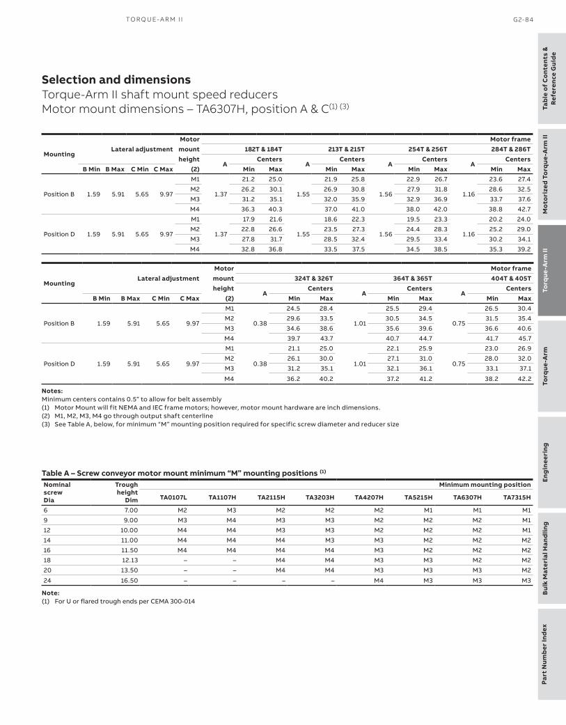
Part
Num
ber
Ind
exEn
gin
eeri
ngB
ulk
Mat
eria
l Han
dlin
gTo
rque
-Arm
To
rque
-Arm
IIM
oto
rize
d To
rque
-Arm
IITa
ble
of
Co
nten
ts &
Ref
eren
ce G
uid
e
TO R Q U E- A R M I I G2-84
Selection and dimensionsTorque-Arm II shaft mount speed reducersMotor mount dimensions – TA6307H, position A & C(1) (3)
Notes:Minimum centers contains 0.5” to allow for belt assembly(1) Motor Mount will fit NEMA and IEC frame motors; however, motor mount hardware are inch dimensions.(2) M1, M2, M3, M4 go through output shaft centerline(3) See Table A, below, for minimum “M” mounting position required for specific screw diameter and reducer size
Table A – Screw conveyor motor mount minimum “M” mounting positions (1)
NominalscrewDia
Troughheight
Dim
Minimum mounting position
TA0107L TA1107H TA2115H TA3203H TA4207H TA5215H TA6307H TA7315H
6 7.00 M2 M3 M2 M2 M2 M1 M1 M1
9 9.00 M3 M4 M3 M3 M2 M2 M2 M1
12 10.00 M4 M4 M3 M3 M2 M2 M2 M1
14 11.00 M4 M4 M4 M3 M3 M2 M2 M2
16 11.50 M4 M4 M4 M4 M3 M2 M2 M2
18 12.13 – – M4 M4 M3 M3 M2 M2
20 13.50 – – M4 M4 M3 M3 M3 M2
24 16.50 – – – – M4 M3 M3 M3
Note:(1) For U or flared trough ends per CEMA 300-014
MountingLateral adjustment
Motor Motor framemount 182T & 184T 213T & 215T 254T & 256T 284T & 286Theight
ACenters
ACenters
ACenters
ACenters
B Min B Max C Min C Max (2) Min Max Min Max Min Max Min Max
Position B 1.59 5.91 5.65 9.97
M1
1.37
21.2 25.0
1.55
21.9 25.8
1.56
22.9 26.7
1.16
23.6 27.4
M2 26.2 30.1 26.9 30.8 27.9 31.8 28.6 32.5
M3 31.2 35.1 32.0 35.9 32.9 36.9 33.7 37.6
M4 36.3 40.3 37.0 41.0 38.0 42.0 38.8 42.7
Position D 1.59 5.91 5.65 9.97
M1
1.37
17.9 21.6
1.55
18.6 22.3
1.56
19.5 23.3
1.16
20.2 24.0
M2 22.8 26.6 23.5 27.3 24.4 28.3 25.2 29.0
M3 27.8 31.7 28.5 32.4 29.5 33.4 30.2 34.1
M4 32.8 36.8 33.5 37.5 34.5 38.5 35.3 39.2
MountingLateral adjustment
Motor Motor framemount 324T & 326T 364T & 365T 404T & 405Theight
ACenters
ACenters
ACenters
B Min B Max C Min C Max (2) Min Max Min Max Min Max
Position B 1.59 5.91 5.65 9.97
M1
0.38
24.5 28.4
1.01
25.5 29.4
0.75
26.5 30.4
M2 29.6 33.5 30.5 34.5 31.5 35.4
M3 34.6 38.6 35.6 39.6 36.6 40.6
M4 39.7 43.7 40.7 44.7 41.7 45.7
Position D 1.59 5.91 5.65 9.97
M1
0.38
21.1 25.0
1.01
22.1 25.9
0.75
23.0 26.9
M2 26.1 30.0 27.1 31.0 28.0 32.0
M3 31.2 35.1 32.1 36.1 33.1 37.1
M4 36.2 40.2 37.2 41.2 38.2 42.2

Table o
f Co
ntents &R
eference Guid
eTo
rque-A
rm II
Mo
torized To
rque-A
rm II
Torq
ue-Arm
Eng
ineeringB
ulk Material H
andling
Part Num
ber Ind
ex
G2-85 D O D G E ® TO RQ U E - A R M A N D MTA I I G E A R I N G EN G I N EER I N G C ATA LO G
Selection and dimensionsTorque-Arm II shaft mount speed reducersTaper bushed reducers – TA7315H, single and double reductions
TA7315H Taper bushed reducers and accessories
All dimensions are in inches.

Part
Num
ber
Ind
exEn
gin
eeri
ngB
ulk
Mat
eria
l Han
dlin
gTo
rque
-Arm
To
rque
-Arm
IIM
oto
rize
d To
rque
-Arm
IITa
ble
of
Co
nten
ts &
Ref
eren
ce G
uid
e
TO R Q U E- A R M I I G2-86
Selection and dimensionsTorque-Arm II shaft mount speed reducersTaper bushed reducers – TA7315H, single and double reductions
TA7315H Taper Bushed Reducers (1) TA7315H AccessoriesReducersize
Part number
AGMAcode
Actualratio
Weightlbs.
DescriptionPart
numberWeight
lbs.TA7315H05 907004 315S05 5.19 449.0 TA7315/8407RA Rod assembly (1) + 907109 43.2
TA7315H09 907003 315D09 9.72 494.0 TA7315BS Backstop assembly (5, 9, 15, 25:1) (2) 907102 20.0
TA7315H15 907002 315D15 14.91 493.0 TA7315/9415BS 40:1 Backstop assembly (2) 907103 21.0
TA7315H25 907001 315D25 24.84 494.0 TA7315/8407MM Motor mount assembly (213-405T) (3) 907090 183.3
TA7315H40 907000 315D40 39.66 492.0 TA7315/8407BG Belt guard - Pos. B (213-405T) 907096 147.2TA7315, 8407 Belt guard assembly Pos. B M2 907101 161.0TA7315/8407BG Belt guard - Pos. C (213-405T) (4) 907097 152.7
TA7315/8407BG Belt guard - Pos. D (213-405T) 907099 148.2
TA7315/8407CF Cooling fan assembly ● 907106 10.0
TA4-TA9 Hydra-Lock dessicant breather kit HL1 964364 2.0
XT Enclosed breather system, TA0-9 240050 2.0
TA4-TA12 Vertical breather kit 904112 2.0
TA7315/8407H V-Ring kit 907249 0.4
TA7315H Lube kit LUBEKITTA7315 53.2
ABB ability sensor 750000 0.5
(1) Reducers are supplied from stock ready for vertical mounting and for flange mounting. Rod assembly is not included with reducer, must order as a separate part number.
+ Rod assembly mounting locations are limited to positions show in drawing.
(2) See page G2-127 for input shaft speed necessary for backstop sprag lift-off(3) Motor Mount will fit NEMA and IEC frame motors; however, motor mount
hardware are inch dimensions..(4) Use Position-C belt guard for TA II reducer in screw conveyor drive applications● See page G2-118 for cooling fan dimensions
▲ AGMA maximum bore size (5) Bushing kit required to mount TA II reducer to driven shaft (6) Bushing kit is not required to mount TA II reducer on screw conveyor drive shaft in a screw conveyor application (7) Standard shaft bushing kit includes two standard bushings with back-up plates and snap rings; hardware, and key. (8) Short shaft bushing kit includes one standard bushing, one long bushing with insertable wedge; two back-up plates with snap rings; hardware and key. This is an optional bushing for after market, short shaft mounting. (9) Minimum keyseat and shaft length required to mount reducer with bushing kit (10) Always check the driven shaft and key for strength
Closed bushing covers may not be compatible with belt guards or large sheave installationsSplit bushing covers are designed for use on “driven machine” side of reducer with shaft through(12) ABS Polymer covers are designed with bolts for tapped reducers, non tapped reducers will require self tapping screws and customer modification of
reducer
TA7315H Tapered Bushing Kits (5) (6)
Bushing size
Partnumber
Weightlbs.
Shaft keyseat
Bushing sizePart
numberWeight
lbs.
Shaft Standard Short shaft keyseatshaft required bushing kit requiredbushing kit (7) (9) (10) (8) (9) (10)TA7315TB x 4-7/16 907019 20.5 1 x 1/2 x 11.87 – – – –TA7315TB x 4-3/16 907021 23.5 1 x 1/2 x 11.87 – – – –TA7315TB x 3-15/16 ▲ 907022 26.3 1 x 1/2 x 11.87 TA7315TBS x 3-15/16 907031 26.7 1 x 1/2 x 7.62TA7315TB x 3-7/16 907023 30.9 7/8 x 7/16 x 11.87 TA7315TBS x 3-7/16 907032 34.2 7/8 x 7/16 x 7.62TA7315TB x 3-3/16 907024 32.6 3/4 x 3/8 x 11.87 TA7315TBS x 3-3/16 907033 36.7 3/4 x 3/8 x 7.62TA7315TB x 3 907025 34.0 3/4 x 3/8 x 11.87 TA7315TBS x 3 907034 38.8 3/4 x 3/8 x 7.62TA7315TB x 2-15/16 907026 34.6 3/4 x 3/8 x 11.87 TA7315TBS x 2-15/16 907035 39.6 3/4 x 3/8 x 7.62TA7315TB x 2-7/8 907027 35.0 3/4 x 3/8 x 11.87 TA7315TBS x 2-7/8 907036 40.2 3/4 x 3/8 x 7.62TA7315TB x 2-11/16 907028 35.8 5/8 x 5/16 x 11.87 TA7315TBS x 2-11/16 907037 41.7 5/8 x 5/16 x 7.62TA7315TB x 2-1/2 907029 37.2 5/8 x 5/16 x 11.87 TA7315TBS x 2-1/2 907038 43.6 5/8 x 5/16 x 7.62TA7315TB x 2-7/16 907030 37.4 5/8 x 5/16 x 11.87 TA7315TBS x 2-7/16 907039 44.1 5/8 x 5/16 x 7.62
Bushing covers
Reducer size Description Part number Weight
TA7315H ABS Polymer closed (12) 907142 1.6
TA7315H ABS Polymer split (12) 907143 1.5

Table o
f Co
ntents &R
eference Guid
eTo
rque-A
rm II
Mo
torized To
rque-A
rm II
Torq
ue-Arm
Eng
ineeringB
ulk Material H
andling
Part Num
ber Ind
ex
G2-87 D O D G E ® TO RQ U E - A R M A N D MTA I I G E A R I N G EN G I N EER I N G C ATA LO G
Selection and dimensionsTorque-Arm II shaft mount speed reducersScrew conveyor drive – TA7315H, single and double reductions
Screw conveyor drive reducers and accessories
All dimensions are in inches.

Part
Num
ber
Ind
exEn
gin
eeri
ngB
ulk
Mat
eria
l Han
dlin
gTo
rque
-Arm
To
rque
-Arm
IIM
oto
rize
d To
rque
-Arm
IITa
ble
of
Co
nten
ts &
Ref
eren
ce G
uid
e
TO R Q U E- A R M I I G2-88
Selection and dimensionsTorque-Arm II shaft mount speed reducersScrew conveyor drive – TA7315H, single and double reductions
(1) Pos “C” Belt guard most popular for screw conveyor drive applications(2) SCA Adapter & hardware kit includes adapter, mounting wedge, keeper plate, key, seals and hardware(3) SCP Adjustable packing kit consists of flange, mounting hardware and braided packing seals(4) SCS Drive shaft is a shaft only. Hardware is stocked with the adapter & hardware kit.(5) A complete TA II screw conveyor drive, order a TA II reducer, SCA adapter & hardware kit, and SCS drive shaft.
The SCP adjustable packing kit is an optional accessory.
TA7315H Accessories for screw conveyor drives (1) (4) (5)
Description Part number Weight lbs.TA7315SCA Adapter & Hardware Kit (2) 907070 50.1
TA7315SCP Adjustable Packing Kit (3) 907071 2.5
TA7315SCS x 2-7/16 Drive Shaft 907074 77.0
TA7315SCS x 3 Drive Shaft 907075 83.4
TA7315SCS x 3-7/16Drive Shaft 907076 97.3
TA7315SCS x 2-7/16 Stainless Steel Drive Shaft 907082 77.0
TA7315SCS x 3 Stainless Steel Drive Shaft 907083 83.4
TA7315SCS x 3-7/16 Stainless Steel Drive Shaft 907084 97.3
TA7315/8407MM Motor mount assembly (213-405T) 907090 183.7
TA7315/8407BG Belt guard - Pos. C (213-405T) š1ť 907097 152.7
TA4-TA9 Hydra-Lock dessicant breather kit HL1 964364 2.0
XT Enclosed breather system, TA0-9 240050 2.0
ABB ability sensor 750000 0.5
TA7315H Screw conveyor drive dimensions
Screwdiameter
Drive Dimensionsshaft
B C D Hole
F GBolt
Dia A Dia E Dia H
12, 14 2-7/16 9.69 2.75 3.00 21/32 0.75 5.63 5/8
12, 14, 16,18, 20 3 9.88 2.88 3.00 25/32 0.75 6.00 3/4
18, 20, 24 3-7/16 13.13 3.88 4.00 29/32 0.75 6.75 7/8

Table o
f Co
ntents &R
eference Guid
eTo
rque-A
rm II
Mo
torized To
rque-A
rm II
Torq
ue-Arm
Eng
ineeringB
ulk Material H
andling
Part Num
ber Ind
ex
G2-89 D O D G E ® TO RQ U E - A R M A N D MTA I I G E A R I N G EN G I N EER I N G C ATA LO G
Selection and dimensionsTorque-Arm II shaft mount speed reducersMotor mount dimensions – TA7315H, position B & D
Motor mount dimensions
All dimensions are in inches.

Part
Num
ber
Ind
exEn
gin
eeri
ngB
ulk
Mat
eria
l Han
dlin
gTo
rque
-Arm
To
rque
-Arm
IIM
oto
rize
d To
rque
-Arm
IITa
ble
of
Co
nten
ts &
Ref
eren
ce G
uid
e
TO R Q U E- A R M I I G2-90
Selection and dimensionsTorque-Arm II shaft mount speed reducersMotor mount dimensions – TA7315H, position B & D (1)
Notes:Minimum centers contains 0.5” to allow for belt assembly(1) Motor Mount will fit NEMA and IEC frame motors; however, motor mount hardware are inch dimensions.(2) M1, M2, M3 go through output shaft centerline
MountingLateral adjustment
Motor Motor framemount 213T & 215T 254T & 256T 284T & 286Theight
ACenters
ACenters
ACenters
B Min B Max C Min C Max (2) Min Max Min Max Min Max
Position B 1.59 5.91 4.78 9.10M1
1.5530.0 34.0
1.5631.0 35.0
1.1631.8 35.7
M2 36.0 40.0 37.0 40.9 37.7 41.7M3 41.9 45.9 42.9 46.9 43.6 47.6
Position D 1.59 5.91 4.78 9.10M1
1.5520.5 24.4
1.5621.5 25.4
1.1622.2 26.1
M2 26.4 30.3 27.4 31.3 28.1 32.0M3 32.3 36.3 33.3 37.2 34.0 38.0
MountingLateral adjustment
Motor Motor framemount 324T & 326T 364T & 365T 404T & 405Theight
ACenters
ACenters
ACenters
B Min B Max C Min C Max (2) Min Max Min Max Min Max
Position B 1.59 5.91 4.78 9.10M1
0.3832.8 36.7
1.0133.7 37.7
0.7534.7 38.7
M2 38.7 42.7 39.7 43.7 40.7 44.7M3 44.6 48.6 45.6 49.6 46.6 50.6
Position D 1.59 5.91 4.78 9.10
M1
0.38
23.2 27.1
1.01
24.2 28.1
0.75
25.1 29.1M2 29.1 33.0 30.1 34.0 31.0 35.0
M3 35.0 39.0 36.0 40.0 37.0 41.0

Table o
f Co
ntents &R
eference Guid
eTo
rque-A
rm II
Mo
torized To
rque-A
rm II
Torq
ue-Arm
Eng
ineeringB
ulk Material H
andling
Part Num
ber Ind
ex
G2-91 D O D G E ® TO RQ U E - A R M A N D MTA I I G E A R I N G EN G I N EER I N G C ATA LO G
Selection and dimensionsTorque-Arm II shaft mount speed reducersMotor mount dimensions – TA7315H, position A & C
All dimensions are in inches.

Part
Num
ber
Ind
exEn
gin
eeri
ngB
ulk
Mat
eria
l Han
dlin
gTo
rque
-Arm
To
rque
-Arm
IIM
oto
rize
d To
rque
-Arm
IITa
ble
of
Co
nten
ts &
Ref
eren
ce G
uid
e
TO R Q U E- A R M I I G2-92
Selection and dimensionsTorque-Arm II shaft mount speed reducersMotor mount dimensions – TA7315H, position A & C(1) (3)
Notes:Minimum centers contains 0.5” to allow for belt assembly(1) Motor Mount will fit NEMA and IEC frame motors; however, motor mount hardware are inch dimensions.(2) M1, M2, M3, M4 go through output shaft centerline(3) See Table A, below, for minimum “M” mounting position required for specific screw diameter and reducer size
Table A – Screw conveyor motor mount minimum “M” mounting positions (1)
NominalscrewDia
Troughheight
Dim
Minimum mounting position
TA0107L TA1107H TA2115H TA3203H TA4207H TA5215H TA6307H TA7315H
6 7.00 M2 M3 M2 M2 M2 M1 M1 M1
9 9.00 M3 M4 M3 M3 M2 M2 M2 M1
12 10.00 M4 M4 M3 M3 M2 M2 M2 M1
14 11.00 M4 M4 M4 M3 M3 M2 M2 M2
16 11.50 M4 M4 M4 M4 M3 M2 M2 M2
18 12.13 – – M4 M4 M3 M3 M2 M2
20 13.50 – – M4 M4 M3 M3 M3 M2
24 16.50 – – – – M4 M3 M3 M3
Note:(1) For U or flared trough ends per CEMA 300-014
MountingLateral adjustment
Motor Motor framemount 213T & 215T 254T & 256T 284T & 286Theight
ACenters
ACenters
ACenters
B Min B Max C Min C Max (2) Min Max Min Max Min Max
Position B 1.59 5.91 6.04 10.36
M1
1.55
27.4 31.4
1.56
28.4 32.4
1.16
29.1 33.1
M2 33.3 37.3 34.3 38.3 35.0 39.0
M3 39.2 43.2 40.2 44.2 41.0 45.0
M4 45.2 49.2 46.2 50.2 46.9 50.9
Position D 1.59 5.91 6.04 10.36
M1
1.55
17.4 21.3
1.56
18.4 22.2
1.16
19.1 23.0
M2 23.2 27.1 24.2 28.1 24.9 28.8
M3 29.1 33.0 30.0 34.0 30.8 34.7
M4 35.0 39.0 36.0 39.9 36.7 40.7
MountingLateral adjustment
Motor Motor framemount 324T & 326T 364T & 365T 404T & 405Theight
ACenters
ACenters
ACenters
B Min B Max C Min C Max (2) Min Max Min Max Min Max
Position B 1.59 5.91 6.04 10.36
M1
0.38
30.1 34.1
1.01
31.1 35.1
0.75
32.1 36.1
M2 36.0 40.0 37.0 41.0 38.0 42.0
M3 42.0 46.0 43.0 47.0 44.0 48.0
M4 47.9 51.9 48.9 52.9 49.9 53.9
Position D 1.59 5.91 6.04 10.36
M1
0.38
20.0 23.9
1.01
21.0 24.9
0.75
22.0 25.9
M2 25.9 29.8 26.9 30.8 27.8 31.8
M3 31.8 35.7 32.8 36.7 33.7 37.7
M4 37.7 41.7 38.7 42.7 39.7 43.7

Table o
f Co
ntents &R
eference Guid
eTo
rque-A
rm II
Mo
torized To
rque-A
rm II
Torq
ue-Arm
Eng
ineeringB
ulk Material H
andling
Part Num
ber Ind
ex
G2-93 D O D G E ® TO RQ U E - A R M A N D MTA I I G E A R I N G EN G I N EER I N G C ATA LO G
Selection and dimensionsTorque-Arm II shaft mount speed reducersTaper bushed reducers – TA8407H, double reductions
TA8407H Taper bushed reducers and accessories
All dimensions are in inches.

Part
Num
ber
Ind
exEn
gin
eeri
ngB
ulk
Mat
eria
l Han
dlin
gTo
rque
-Arm
To
rque
-Arm
IIM
oto
rize
d To
rque
-Arm
IITa
ble
of
Co
nten
ts &
Ref
eren
ce G
uid
e
TO R Q U E- A R M I I G2-94
Selection and dimensionsTorque-Arm II shaft mount speed reducersTaper bushed reducers – TA8407H, double reductions
TA8407H Taper Bushed Reducers (1) TA8407H AccessoriesReducersize
Part number
AGMAcode
Actualratio
Weightlbs.
DescriptionPart
numberWeight
lbs.TA8407H15 908002 407D15 15.12 511.0 TA7315/8407RA Rod Assembly (1) + 907109 43.2TA8407H25 908001 407D25 24.97 511.0 TA8407BS Backstop Assembly (15, 25:1) (2) 908102 15.0TA8407H40 908000 407D40 39.67 507.0 TA8407BS 40:1 Backstop Assembly (2) 908103 15.7
TA7315/8407MM Motor Mount Assembly (213-405T) (3) 907090 183.3
TA7315/8407BG Belt Guard - Pos. B (213-405T) 907096 147.2TA7315, 8407 Belt guard assembly Pos. B M2 907101 161.0TA7315/8407BG Belt Guard - Pos. C (213-405T) 907097 152.7TA7315/8407BG Belt Guard - Pos. D (213-405T) 907099 148.2TA7315/8407CF Cooling Fan Assembly ● 907106 10.0TA4-TA9 Hydra-Lock Dessicant Breather Kit HL1 964364 2.0XT Enclosed Breather System, TA0-9 240050 2.0TA4-TA12 Vertical Breather Kit 904112 2.0TA7315/8407H V-Ring Kit 907249 0.4TA8407H Lube Kit LUBEKITTA8407 53.2ABB ability sensor 750000 0.5
(1) Reducers are supplied from stock ready for vertical mounting and for flange mounting. Rod assembly is not included with reducer, must order as a separate part number.
+ Rod assembly mounting locations are limited to positions show in drawing.
(2) See page G2-127 for input shaft speed necessary for backstop sprag lift-off(3) Motor Mount will fit NEMA and IEC frame motors; however, motor mount
hardware are inch dimensions.● See page G2-118 for cooling fan dimensions◆ SCA Adapter & Hardware Kit is available for TA8407H reducers as a non-stock
product. Consult
▲ AGMA maximum bore size (4) Bushing kit required to mount TA II reducer to driven shaft (5) Bushing kit is not required to mount TA II reducer on screw conveyor drive shaft in a screw conveyor application (6) Standard shaft bushing kit includes two standard bushings with back-up plates and snap rings; hardware, and key. (7) Short shaft bushing kit includes one standard bushing, one long bushing with insertable wedge; two back-up plates with snap rings; hardware and key. This is an optional bushing for after market, short shaft mounting. (8) Minimum keyseat and shaft length required to mount reducer with bushing kit (9) Always check the driven shaft and key for strength
Closed bushing covers may not be compatible with belt guards or large sheave installationsSplit bushing covers are designed for use on “driven machine” side of reducer with shaft through(12) ABS Polymer covers are designed with bolts for tapped reducers, non tapped reducers will require self tapping screws and customer modification of
reducer
TA8407H Tapered Bushing Kits (4) (5)
Bushing size
Partnumber
Weightlbs.
Shaft keyseat
Bushing sizePart
numberWeight
lbs.
Shaft Standard Short shaft keyseatshaft required bushing kit requiredbushing kit (6) (8) (9) (7) (8) (9)TA8407TB x 4-7/16 ▲ 908020 26.0 1 x 1/2 x 12.82 TA8407TBS x 4-7/16 908027 26.9 1 x 1/2 x 8.10
TA8407TB x 4-3/16 908021 29.0 1 x 1/2 x 12.82 TA8407TBS x 4-3/16 908028 31.3 1 x 1/2 x 8.10
TA8407TB x 3-15/16 908022 32.1 1 x 1/2 x 12.82 TA8407TBS x 3-15/16 908029 35.6 1 x 1/2 x 8.10
TA8407TB x 3-7/16 908023 36.7 7/8 x 7/16 x 12.82 TA8407TBS x 3-7/16 908030 42.4 7/8 x 7/16 x 8.10
TA8407TB x 3-3/16 908024 38.4 3/4 x 3/8 x 12.82 TA8407TBS x 3-3/16 908031 45.3 3/4 x 3/8 x 8.10
TA8407TB x 3 908025 39.8 3/4 x 3/8 x 12.82 TA8407TBS x 3 908032 47.5 3/4 x 3/8 x 8.10
TA8407TB x 2-15/16 908026 40.4 3/4 x 3/8 x 12.82 TA8407TBS x 2-15/16 908033 48.3 3/4 x 3/8 x 8.10
Bushing covers
Reducer size Description Part number Weight
TA8407H ABS Polymer closed (12) 908142 1.7
TA8407H ABS Polymer split (12) 908143 1.6

Table o
f Co
ntents &R
eference Guid
eTo
rque-A
rm II
Mo
torized To
rque-A
rm II
Torq
ue-Arm
Eng
ineeringB
ulk Material H
andling
Part Num
ber Ind
ex
G2-95 D O D G E ® TO RQ U E - A R M A N D MTA I I G E A R I N G EN G I N EER I N G C ATA LO G
Selection and dimensionsTorque-Arm II shaft mount speed reducersMotor mount dimensions – TA8407H, position B & D
Motor mount dimensions
All dimensions are in inches.

Part
Num
ber
Ind
exEn
gin
eeri
ngB
ulk
Mat
eria
l Han
dlin
gTo
rque
-Arm
To
rque
-Arm
IIM
oto
rize
d To
rque
-Arm
IITa
ble
of
Co
nten
ts &
Ref
eren
ce G
uid
e
TO R Q U E- A R M I I G2-96
Selection and dimensionsTorque-Arm II shaft mount speed reducersMotor mount dimensions – TA8407H, position B & D (1)
Notes:Minimum centers contains 0.5” to allow for belt assembly(1) Motor Mount will fit NEMA and IEC frame motors; however, motor mount hardware are inch dimensions.(2) M1, M2, M3 go through output shaft centerline
MountingLateral adjustment
Motor Motor framemount 213T & 215T 254T & 256T 284T & 286Theight
ACenters
ACenters
ACenters
B Min B Max C Min C Max (2) Min Max Min Max Min Max
Position B 1.59 5.91 5.78 10.10M1
1.5530.2 34.2
1.5631.2 35.2
1.1632.0 35.9
M2 36.2 40.1 37.1 41.1 37.9 41.9M3 42.1 46.1 43.1 47.1 43.8 47.8
Position D 1.59 5.91 5.78 10.10M1
1.5520.3 24.2
1.5621.3 25.2
1.1622.0 25.9
M2 26.1 30.1 27.1 31.1 27.9 31.8M3 32.1 36.0 33.0 37.0 33.8 37.8
MountingLateral adjustment
Motor Motor framemount 324T & 326T 364T & 365T 404T & 405Theight
ACenters
ACenters
ACenters
B Min B Max C Min C Max (2) Min Max Min Max Min Max
Position B 1.59 5.91 5.78 10.10M1
0.3832.9 36.9
1.0133.9 37.9
0.7534.9 38.9
M2 38.9 42.9 39.9 43.9 40.9 44.9M3 44.8 48.8 45.8 49.8 46.8 50.8
Position D 1.59 5.91 5.78 10.10
M1
0.38
23.0 26.9
1.01
23.9 27.9
0.75
24.9 28.9M2 28.8 32.8 29.8 33.8 30.8 34.8
M3 34.8 38.8 35.8 39.7 36.7 40.7

Table o
f Co
ntents &R
eference Guid
eTo
rque-A
rm II
Mo
torized To
rque-A
rm II
Torq
ue-Arm
Eng
ineeringB
ulk Material H
andling
Part Num
ber Ind
ex
G2-97 D O D G E ® TO RQ U E - A R M A N D MTA I I G E A R I N G EN G I N EER I N G C ATA LO G
Selection and dimensionsTorque-Arm II shaft mount speed reducersMotor mount dimensions – TA8407H, position A & C
All dimensions are in inches.

Part
Num
ber
Ind
exEn
gin
eeri
ngB
ulk
Mat
eria
l Han
dlin
gTo
rque
-Arm
To
rque
-Arm
IIM
oto
rize
d To
rque
-Arm
IITa
ble
of
Co
nten
ts &
Ref
eren
ce G
uid
e
TO R Q U E- A R M I I G2-98
Selection and dimensionsTorque-Arm II shaft mount speed reducersMotor mount dimensions – TA8407H, position A & C(1)
Notes:Minimum centers contains 0.5” to allow for belt assembly(1) Motor Mount will fit NEMA and IEC frame motors; however, motor mount hardware are inch dimensions.(2) M1, M2, M3, M4 go through output shaft centerline(3) See Table A, below, for minimum “M” mounting position required for specific screw diameter and reducer size
MountingLateral adjustment
Motor Motor framemount 213T & 215T 254T & 256T 284T & 286Theight
ACenters
ACenters
ACenters
B Min B Max C Min C Max (2) Min Max Min Max Min Max
Position B 1.59 5.91 7.04 11.36
M1
1.55
27.4 31.3
1.56
28.3 32.3
1.16
29.1 33.0M2 33.2 37.2 34.2 38.2 35.0 39.0M3 39.2 43.2 40.2 44.2 40.9 44.9M4 45.1 49.1 46.1 50.1 46.9 50.9
Position D 1.59 5.91 7.04 11.36
M1
1.55
17.6 21.4
1.56
18.5 22.4
1.16
19.2 23.1M2 23.3 27.3 24.3 28.2 25.0 29.0M3 29.2 33.2 30.2 34.1 30.9 34.9M4 35.1 39.1 36.1 40.1 36.8 40.8
MountingLateral adjustment
Motor Motor framemount 324T & 326T 364T & 365T 404T & 405Theight
ACenters
ACenters
ACenters
B Min B Max C Min C Max (2) Min Max Min Max Min Max
Position B 1.59 5.91 7.04 11.36
M1
0.38
30.1 34.0
1.01
31.0 35.0
0.75
32.0 36.0
M2 36.0 39.9 37.0 40.9 37.9 41.9
M3 41.9 45.9 42.9 46.9 43.9 47.9
M4 47.9 51.9 48.8 52.8 49.8 53.8
Position D 1.59 5.91 7.04 11.36
M1
0.38
20.2 24.1
1.01
21.2 25.1
0.75
22.1 26.0
M2 26.0 30.0 27.0 30.9 28.0 31.9
M3 31.9 35.9 32.9 36.9 33.9 37.8
M4 37.8 41.8 38.8 42.8 39.8 43.8

Table o
f Co
ntents &R
eference Guid
eTo
rque-A
rm II
Mo
torized To
rque-A
rm II
Torq
ue-Arm
Eng
ineeringB
ulk Material H
andling
Part Num
ber Ind
ex
G2-99 D O D G E ® TO RQ U E - A R M A N D MTA I I G E A R I N G EN G I N EER I N G C ATA LO G
Selection and dimensionsTorque-Arm II shaft mount speed reducersTaper bushed reducers – TA9415H, double reductions
TA9415H Taper bushed reducers and accessories
All dimensions are in inches.

Part
Num
ber
Ind
exEn
gin
eeri
ngB
ulk
Mat
eria
l Han
dlin
gTo
rque
-Arm
To
rque
-Arm
IIM
oto
rize
d To
rque
-Arm
IITa
ble
of
Co
nten
ts &
Ref
eren
ce G
uid
e
TO R Q U E- A R M I I G2-100
Selection and dimensionsTorque-Arm II shaft mount speed reducersTaper bushed reducers – TA9415H, double reductions
TA9415H Taper Bushed Reducers (1) TA9415H AccessoriesReducersize
Part number
AGMAcode
Actualratio
Weightlbs.
DescriptionPart
numberWeight
lbs.TA9415H15 909002 415D15 15.10 735.0 TA9415RA Rod Assembly (1) + 909109 76.8
TA9415H25 909001 415D25 25.44 735.0 TA9415BS Backstop Assembly (15, 25:1) (2) 909102 20.0
TA9415H40 909000 415D40 39.41 732.0 TA7315/9415BS 40:1 Backstop Assembly (2) 907103 21.0
TA9415MM Motor Mount Assembly (254-445T) (3) 909090 273.7
TA9415BG Belt Guard - Pos. B (254-445T) 909096 158.1TA9415 Belt guard assembly Pos. B M2 909101 190.0TA9415BG Belt Guard - Pos. D (254-445T) 909099 159.1
TA9415CF Cooling Fan Assembly ● 909106 12.4
TA4-TA9 Hydra-Lock Dessicant Breather Kit HL1 964364 2.0
XT Enclosed Breather System, TA0-9 240050 2.0
TA4-TA12 Vertical Breather Kit 904112 2.0
TA9415H V-Ring Kit 909249 0.5
TA9415H Lube Kit LUBEKITTA9415 79.8
ABB ability sensor 750000 0.5
(1) Reducers are supplied from stock ready for vertical mounting and for flange mounting. Rod assembly is not included with reducer, must order as a separate part number.
+ Rod assembly mounting locations are limited to positions show in drawing.
(2) See page G2-127 for input shaft speed necessary for backstop sprag lift-off(3) Motor Mount will fit NEMA and IEC frame motors; however, motor mount
hardware are inch dimensions.● See page G2-118 for cooling fan dimensions
▲ AGMA maximum bore size (4) Bushing kit required to mount TA II reducer to driven shaft (5) Standard shaft bushing kit includes two standard bushings with back-up plates and snap rings; hardware, and key. (6) Short shaft bushing kit includes one standard bushing, one long bushing with insertable wedge; two back-up plates with snap rings; hardware and key. This is an optional bushing for after market, short shaft mounting. (7) Minimum keyseat and shaft length required to mount reducer with bushing kit (8) Always check the driven shaft and key for strength
Closed bushing covers may not be compatible with belt guards or large sheave installationsSplit bushing covers are designed for use on “driven machine” side of reducer with shaft through(12) ABS Polymer covers are designed with bolts for tapped reducers, non tapped reducers will require self tapping screws and customer modification of
reducer
TA9415H Tapered Bushing Kits (4)
Bushing size
Partnumber
Weightlbs.
Shaft keyseat
Bushing sizePart
numberWeight
lbs.
Shaft Standard Short shaft keyseatshaft required bushing kit requiredbushing kit (5) (7) (8) (6) (7) (8)TA9415TB x 4-15/16 ▲ 909020 38.4 1-1/4 x 5/8 x 13.74 TA9415TBS x 4-15/16 909025 40.2 1-1/4 x 5/8 x 8.56
TA9415TB x 4-7/16 909021 43.4 1 x 1/2 x 13.74 TA9415TBS x 4-7/16 909026 48.8 1 x 1/2 x 8.56
TA9415TB x 4-3/16 909022 46.4 1 x 1/2 x 13.74 TA9415TBS x 4-3/16 909027 53.4 1 x 1/2 x 8.56
TA9415TB x 3-15/16 909023 49.2 1 x 1/2 x 13.74 TA9415TBS x 3-15/16 909028 57.7 1 x 1/2 x 8.56
TA9415TB x 3-7/16 909024 53.1 7/8 x 7/16 x 13.74 TA9415TBS x 3-7/16 909029 64.4 7/8 x 7/16 x 8.56
Bushing covers
Reducer size Description Part number Weight
TA9415H ABS Polymer closed (12) 909142 2.0
TA9415H ABS Polymer split (12) 909143 1.8

Table o
f Co
ntents &R
eference Guid
eTo
rque-A
rm II
Mo
torized To
rque-A
rm II
Torq
ue-Arm
Eng
ineeringB
ulk Material H
andling
Part Num
ber Ind
ex
G2-101 D O D G E ® TO RQ U E - A R M A N D MTA I I G E A R I N G EN G I N EER I N G C ATA LO G
Selection and dimensionsTorque-Arm II shaft mount speed reducersMotor mount dimensions – TA9415H, position B & D
Motor mount dimensions
All dimensions are in inches.

Part
Num
ber
Ind
exEn
gin
eeri
ngB
ulk
Mat
eria
l Han
dlin
gTo
rque
-Arm
To
rque
-Arm
IIM
oto
rize
d To
rque
-Arm
IITa
ble
of
Co
nten
ts &
Ref
eren
ce G
uid
e
TO R Q U E- A R M I I G2-102
Selection and dimensionsTorque-Arm II shaft mount speed reducersMotor mount dimensions – TA9415H, position B & D (1)
Notes:Minimum centers contains 0.5” to allow for belt assembly(1) Motor Mount will fit NEMA and IEC frame motors; however, motor mount hardware are inch dimensions.(2) M1, M2, M3 go through output shaft centerline
MountingLateral adjustment
Motor Motor framemount 254T & 256T 284T & 286T 324T & 326Theight
ACenters
ACenters
ACenters
B Min B Max C Min C Max (2) Min Max Min Max Min Max
Position B 2.18 6.82 6.26 10.90M1
1.5635.5 39.2
1.1636.2 40.0
0.3837.2 41.0
M2 40.5 44.2 41.2 45.0 42.2 46.0
Position D 2.18 6.82 6.26 10.90M1
1.5621.3 25.0
1.1622.0 25.7
0.3823.0 26.7
M2 26.2 29.9 26.9 30.6 27.9 31.6
MountingLateral adjustment
Motor Motor framemount 364T & 365T 404T & 405T 444T & 445Theight
ACenters
ACenters
ACenters
B Min B Max C Min C Max (2) Min Max Min Max Min Max
Position B 2.18 6.82 6.26 10.90M1
1.0138.2 42.0
0.7539.2 43.0
1.6240.2 44.0
M2 43.2 47.0 44.2 47.9 45.2 48.9
Position D 2.18 6.82 6.26 10.90M1
1.0124.0 27.7
0.7525.0 28.7
1.6225.9 29.7
M2 28.9 32.6 29.9 33.6 30.9 34.6

Table o
f Co
ntents &R
eference Guid
eTo
rque-A
rm II
Mo
torized To
rque-A
rm II
Torq
ue-Arm
Eng
ineeringB
ulk Material H
andling
Part Num
ber Ind
ex
G2-103 D O D G E ® TO RQ U E - A R M A N D MTA I I G E A R I N G EN G I N EER I N G C ATA LO G
Selection and dimensionsTorque-Arm II shaft mount speed reducersTaper bushed reducers – TA10507H, double reductions
TA10507H Taper bushed reducers and accessories
All dimensions are in inches.

Part
Num
ber
Ind
exEn
gin
eeri
ngB
ulk
Mat
eria
l Han
dlin
gTo
rque
-Arm
To
rque
-Arm
IIM
oto
rize
d To
rque
-Arm
IITa
ble
of
Co
nten
ts &
Ref
eren
ce G
uid
e
TO R Q U E- A R M I I G2-104
Selection and dimensionsTorque-Arm II shaft mount speed reducersTaper bushed reducers – TA10507H, double reductions
TA10507H Taper Bushed Reducers (1) TA10507H AccessoriesReducersize
Part number
AGMAcode
Actualratio
Weightlbs.
DescriptionPart
numberWeight
lbs.TA10507H15 910002 507D15 15.09 1022.0 TA10507RA Rod Assembly (1) + 910109 87.0
TA10507H25 910001 507D25 25.18 1022.0 TA10507BS Backstop Assembly (15, 25:1) (2) 910102 23.5
TA10507H40 910000 507D40 39.68 1018.0 TA10507BS 40:1 Backstop Assembly (2) 910103 25.0
TA10507MM Motor Mount Assembly (254-445T) (3) 910090 286.7
TA10507BG Belt Guard - Pos. B (254-445T) 910096 158.1TA10507 Belt guard assembly Pos. B M2 910101 218.0TA10507BG Belt Guard - Pos. D (254-445T) 910099 175.0
TA10507CF Cooling Fan Assembly ● 910106 12.4
TA10-TA12 Hydra-Lock Dessicent Breather Kit HL2 964366 2.0
XT Enclosed Breather System, TA10-2 240051 2.0
TA4-TA12 Vertical Breather Kit 904112 2.0
TA10507H V-Ring Kit 910249 0.8
TA10507H Lube Kit LUBEKITTA10507 121.5
ABB ability sensor 750000 0.5
(1) Reducers are supplied from stock ready for vertical mounting and for flange mounting. Rod assembly is not included with reducer, must order as a separate part number.
+ Rod assembly mounting locations are limited to positions show in drawing.
(2) See page G2-127 for input shaft speed necessary for backstop sprag lift-off(3) Motor Mount will fit NEMA and IEC frame motors; however, motor mount
hardware are inch dimensions.● See page G2-118 for cooling fan dimensions
▲ AGMA maximum bore size (4) Bushing kit required to mount TA II reducer to driven shaft (5) Standard shaft bushing kit includes two standard bushings with back-up plates and snap rings; hardware, and key. (6) Short shaft bushing kit includes one standard bushing, one long bushing with insertable wedge; two back-up plates with snap rings; hardware and key. This is an optional bushing for after market, short shaft mounting. (7) Minimum keyseat and shaft length required to mount reducer with bushing kit (8) Always check the driven shaft and key for strength
Closed bushing covers may not be compatible with belt guards or large sheave installationsSplit bushing covers are designed for use on “driven machine” side of reducer with shaft through(12) ABS Polymer covers are designed with bolts for tapped reducers, non tapped reducers will require self tapping screws and customer modification of
reducer
TA10507H Tapered Bushing Kits (4)
Bushing size
Partnumber
Weightlbs.
Shaft keyseat
Bushing sizePart
numberWeight
lbs.
Shaft Standard Short shaft keyseatshaft required bushing kit requiredbushing kit (5) (7) (8) (6) (7) (8)TA10507TB x 6 910020 40.8 1-1/2 x 3/4 x 15.46 – – – –
TA10507TB x 5-15/16 910021 43.2 1-1/2 x 3/4 x 15.46 – – – –
TA10507TB x 5-7/16 ▲ 910022 50.0 1-1/4 x 5/8 x 15.46 TA10507TBS x 5-7/16 910027 47.2 1-1/4 x 5/8 x 9.67
TA10507TB x 4-15/16 910023 57.8 1-1/4 x 5/8 x 15.46 TA10507TBS x 4-15/16 910028 66.9 1-1/4 x 5/8 x 9.67
TA10507TB x 4-7/16 910024 52.8 1 x 1/2 x 15.46 TA10507TBS x 4-7/16 910029 75.7 1 x 1/2 x 9.67
TA10507TB x 4-3/16 910025 65.6 1 x 1/2 x 15.46 TA10507TBS x 4-3/16 910030 80.5 1 x 1/2 x 9.67
TA10507TB x 3-15/16 910026 68.4 1 x 1/2 x 15.46 TA10507TBS x 3-15/16 910031 85.2 1 x 1/2 x 9.67
Bushing covers
Reducer size Description Part number Weight
TA10507H ABS Polymer closed (12) 910142 3.0
TA10507H ABS Polymer split (12) 910143 2.8

Table o
f Co
ntents &R
eference Guid
eTo
rque-A
rm II
Mo
torized To
rque-A
rm II
Torq
ue-Arm
Eng
ineeringB
ulk Material H
andling
Part Num
ber Ind
ex
G2-105 D O D G E ® TO RQ U E - A R M A N D MTA I I G E A R I N G EN G I N EER I N G C ATA LO G
Selection and dimensionsTorque-Arm II shaft mount speed reducersMotor mount dimensions – TA10507H, position B & D
Motor mount dimensions
All dimensions are in inches.

Part
Num
ber
Ind
exEn
gin
eeri
ngB
ulk
Mat
eria
l Han
dlin
gTo
rque
-Arm
To
rque
-Arm
IIM
oto
rize
d To
rque
-Arm
IITa
ble
of
Co
nten
ts &
Ref
eren
ce G
uid
e
TO R Q U E- A R M I I G2-106
Selection and dimensionsTorque-Arm II shaft mount speed reducersMotor mount dimensions – TA10507H, position B & D (1)
Notes:Minimum centers contains 0.5” to allow for belt assembly(1) Motor Mount will fit NEMA and IEC frame motors; however, motor mount hardware are inch dimensions.(2) M1, M2, M3 go through output shaft centerline
MountingLateral adjustment
Motor Motor framemount 254T & 256T 284T & 286T 324T & 326Theight
ACenters
ACenters
ACenters
B Min B Max C Min C Max (2) Min Max Min Max Min Max
Position B 2.18 6.82 6.98 11.62M1
1.5646.7 50.5
1.1647.5 51.2
0.3848.5 52.2
M2 52.1 55.9 52.8 56.6 53.8 57.6
Position D 2.18 6.82 6.98 11.62M1
1.5617.7 21.4
1.1618.4 22.2
0.3819.4 23.2
M2 23.0 26.8 23.8 27.5 24.8 28.5
MountingLateral adjustment
Motor Motor framemount 364T & 365T 404T & 405T 444T & 445Theight
ACenters
ACenters
ACenters
B Min B Max C Min C Max (2) Min Max Min Max Min Max
Position B 2.18 6.82 6.98 11.62M1
1.0149.5 53.2
0.7550.5 54.2
1.6251.5 55.2
M2 54.8 58.6 55.8 59.6 56.8 60.6
Position D 2.18 6.82 6.98 11.62M1
1.0120.4 24.2
0.7521.4 25.2
1.6222.4 26.2
M2 25.8 29.5 26.8 30.5 27.8 31.5

Table o
f Co
ntents &R
eference Guid
eTo
rque-A
rm II
Mo
torized To
rque-A
rm II
Torq
ue-Arm
Eng
ineeringB
ulk Material H
andling
Part Num
ber Ind
ex
G2-107 D O D G E ® TO RQ U E - A R M A N D MTA I I G E A R I N G EN G I N EER I N G C ATA LO G
Selection and dimensionsTorque-Arm II shaft mount speed reducersTaper bushed reducers – TA12608H, double reductions
TA12608H Taper bushed reducers and accessories
All dimensions are in inches.

Part
Num
ber
Ind
exEn
gin
eeri
ngB
ulk
Mat
eria
l Han
dlin
gTo
rque
-Arm
To
rque
-Arm
IIM
oto
rize
d To
rque
-Arm
IITa
ble
of
Co
nten
ts &
Ref
eren
ce G
uid
e
TO R Q U E- A R M I I G2-108
Selection and dimensionsTorque-Arm II shaft mount speed reducersTaper bushed reducers – TA12608H, double reductions
TA12608H Taper Bushed Reducers (1) TA12608H AccessoriesReducersize
Part number
AGMAcode
Actualratio
Weightlbs.
DescriptionPart
numberWeight
lbs.TA12608H15 912002 608D15 14.79 1392.0 TA12608RA Rod Assembly (1) + 912109 106.4
TA12608H25 912001 608D25 25.03 1395.0 TA12608BS Backstop Assembly (15, 25:1) (2) 912102 40.0
TA12608H40 912000 608D40 38.19 1393.0 TA12608BS 40:1 Backstop Assembly (2) 912103 41.1
TA12608MM Motor Mount Assembly (254-445T) (3) 912090 289.6
TA12608BG Belt Guard - Pos. B (254-445T) 912096 190.5TA12608 Belt guard assembly Pos. B M2 912101 227.0TA12608BG Belt Guard - Pos. D (254-445T) 912099 181.0
TA12608CF Cooling Fan Assembly ● 912106 13.7
TA10-TA12 Hydra-Lock Dessicant Breather Kit HL2 964366 2.0
XT Enclosed Breather System, TA 10-12 240051 2.0
TA4-TA12 Vertical Breather Kit 904112 2.0
TA12608H V-Ring Kit 912249 0.8
TA12608H Lube Kit LUBEKITTA12608 170.1
ABB ability sensor 750000 0.5
(1) Reducers are supplied from stock ready for vertical mounting and for flange mounting. Rod assembly is not included with reducer and must be ordered as a separate part number.
+ Rod assembly mounting locations are limited to positions show in drawing.
(2) See page G2-127 for input shaft speed necessary for backstop sprag lift-off(3) Motor Mount will fit NEMA and IEC frame motors; however, motor mount
hardware are inch dimensions.● See page G2-118 for cooling fan dimensions
▲ AGMA maximum bore size (4) Bushing kit required to mount TA II reducer to driven shaft (5) Standard shaft bushing kit includes two standard bushings with back-up plates and snap rings; hardware, and key. (6) Short shaft bushing kit includes one standard bushing, one long bushing with insertable wedge; two back-up plates with snap rings; hardware and key. This is an optional bushing for after market, short shaft mounting. (7) Minimum keyseat and shaft length required to mount reducer with bushing kit (8) Always check the driven shaft and key for strength
Closed bushing covers may not be compatible with belt guards or large sheave installationsSplit bushing covers are designed for use on “driven machine” side of reducer with shaft through(12) ABS Polymer covers are designed with bolts for tapped reducers, non tapped reducers will require self tapping screws and customer modification of
reducer
TA12608H Tapered Bushing Kits (4)
Bushing size
Partnumber
Weightlbs.
Shaft keyseat
Bushing sizePart
numberWeight
lbs.
Shaft Standard Short shaft keyseatshaft required bushing kit requiredbushing kit (5) (7) (8) (6) (7) (8)TA12608TB x 7 912020 58.2 1-3/4 x 3/4 x 18.32 – – – –
TA12608TB x 6-1/2 ▲ 912021 67.8 1-1/2 x 3/4 x 18.32 TA12608TBS x 6-1/2 912027 73.5 1-1/2 x 3/4 x 11.60
TA12608TB x 6-7/16 912022 69.1 1-1/2 x 3/4 x 18.32 TA12608TBS x 6-7/16 912028 75.7 1-1/2 x 3/4 x 11.60
TA12608TB x 6 912023 78.1 1-1/2 x 3/4 x 18.32 TA12608TBS x 6 912029 90.5 1-1/2 x 3/4 x 11.60
TA12608TB x 5-15/16 912024 79.4 1-1/2 x 3/4 x 18.32 TA12608TBS x 5-15/16 912030 92.6 1-1/2 x 3/4 x 11.60
TA12608TB x 5-7/16 912025 86.7 1-1/4 x 5/8 x 18.32 TA12608TBS x 5-7/16 912031 106.1 1-1/4 x 5/8 x 11.60
TA12608TB x 4-15/16 912026 94.6 1-1/4 x 5/8 x 18.32 TA12608TBS x 4-15/16 912032 119.3 1-1/4 x 5/8 x 11.60
Bushing covers
Reducer size Description Part number Weight
TA12608H ABS Polymer closed (12) 912142 3.0
TA12608H ABS Polymer split (12) 912143 2.8

Table o
f Co
ntents &R
eference Guid
eTo
rque-A
rm II
Mo
torized To
rque-A
rm II
Torq
ue-Arm
Eng
ineeringB
ulk Material H
andling
Part Num
ber Ind
ex
G2-109 D O D G E ® TO RQ U E - A R M A N D MTA I I G E A R I N G EN G I N EER I N G C ATA LO G
Selection and dimensionsTorque-Arm II shaft mount speed reducersMotor mount dimensions – TA12608H, position B & D
Motor mount dimensions
All dimensions are in inches.

Part
Num
ber
Ind
exEn
gin
eeri
ngB
ulk
Mat
eria
l Han
dlin
gTo
rque
-Arm
To
rque
-Arm
IIM
oto
rize
d To
rque
-Arm
IITa
ble
of
Co
nten
ts &
Ref
eren
ce G
uid
e
TO R Q U E- A R M I I G2-110
Selection and dimensionsTorque-Arm II shaft mount speed reducersMotor mount dimensions – TA12608H, position B & D (1)
Notes:Minimum centers contains 0.5” to allow for belt assembly(1) Motor Mount will fit NEMA and IEC frame motors; however, motor mount hardware are inch dimensions.(2) M1, M2, M3 go through output shaft centerline
MountingLateral adjustment
Motor Motor framemount 254T & 256T 284T & 286T 324T & 326Theight
ACenters
ACenters
ACenters
B Min B Max C Min C Max (2) Min Max Min Max Min Max
Position B 1.68 7.32 8.02 13.66M1
1.5648.9 52.7
1.1649.7 53.5
0.3850.7 54.5
M2 54.5 58.3 55.3 59.1 56.3 60.1Position D 1.68 7.32 8.02 13.66 M1 1.56 22.0 25.8 1.16 22.8 26.6 0.38 23.8 27.6
MountingLateral adjustment
Motor Motor framemount 364T & 365T 404T & 405T 444T & 445Theight
ACenters
ACenters
ACenters
B Min B Max C Min C Max (2) Min Max Min Max Min Max
Position B 1.68 7.32 8.02 13.66M1
1.0151.7 55.5 0.75 52.7 56.5
1.6253.7 57.5
M2 57.3 61.1 – 58.3 62.1 59.3 63.1Position D 1.68 7.32 8.02 13.66 M1 1.01 24.8 28.6 0.75 25.8 29.6 1.62 26.8 30.6

Table o
f Co
ntents &R
eference Guid
eTo
rque-A
rm II
Mo
torized To
rque-A
rm II
Torq
ue-Arm
Eng
ineeringB
ulk Material H
andling
Part Num
ber Ind
ex
G2-111 D O D G E ® TO RQ U E - A R M A N D MTA I I G E A R I N G EN G I N EER I N G C ATA LO G
Selection and dimensionsTorque-Arm II shaft mount speed reducersFull featured Position B – M2 belt guard dimensions, TA0107L – TA12608H
This belt guard offers enhanced safety and maintenance features.
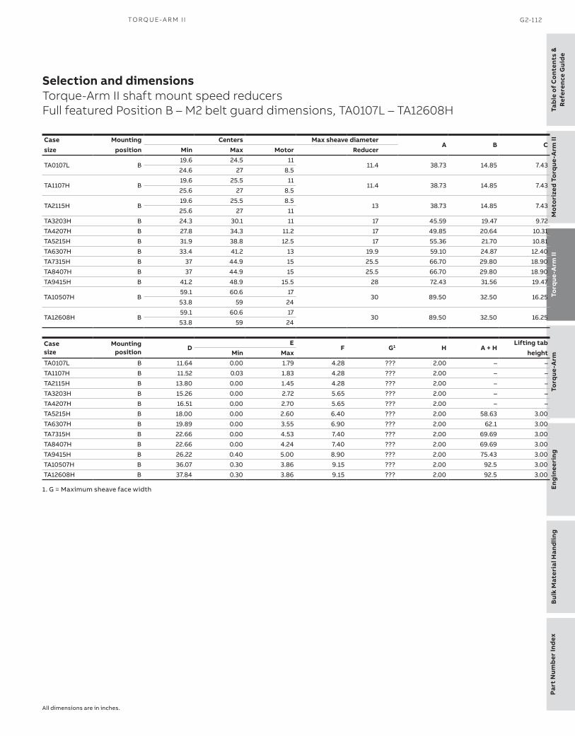
Part
Num
ber
Ind
exEn
gin
eeri
ngB
ulk
Mat
eria
l Han
dlin
gTo
rque
-Arm
To
rque
-Arm
IIM
oto
rize
d To
rque
-Arm
IITa
ble
of
Co
nten
ts &
Ref
eren
ce G
uid
e
TO R Q U E- A R M I I G2-112
Selection and dimensionsTorque-Arm II shaft mount speed reducersFull featured Position B – M2 belt guard dimensions, TA0107L – TA12608H
Case Mounting Centers Max sheave diameterA B C
size position Min Max Motor Reducer
TA0107L B19.6 24.5 11
11.4 38.73 14.85 7.4324.6 27 8.5
TA1107H B19.6 25.5 11
11.4 38.73 14.85 7.4325.6 27 8.5
TA2115H B19.6 25.5 8.5
13 38.73 14.85 7.4325.6 27 11
TA3203H B 24.3 30.1 11 17 45.59 19.47 9.72
TA4207H B 27.8 34.3 11.2 17 49.85 20.64 10.31
TA5215H B 31.9 38.8 12.5 17 55.36 21.70 10.81
TA6307H B 33.4 41.2 13 19.9 59.10 24.87 12.40
TA7315H B 37 44.9 15 25.5 66.70 29.80 18.90
TA8407H B 37 44.9 15 25.5 66.70 29.80 18.90
TA9415H B 41.2 48.9 15.5 28 72.43 31.56 19.47
TA10507H B59.1 60.6 17
30 89.50 32.50 16.2553.8 59 24
TA12608H B59.1 60.6 17
30 89.50 32.50 16.2553.8 59 24
Case size
Mountingposition
DE
F G1 H A + HLifting tab
Min Max heightTA0107L B 11.64 0.00 1.79 4.28 ??? 2.00 – –
TA1107H B 11.52 0.03 1.83 4.28 ??? 2.00 – –
TA2115H B 13.80 0.00 1.45 4.28 ??? 2.00 – –
TA3203H B 15.26 0.00 2.72 5.65 ??? 2.00 – –
TA4207H B 16.51 0.00 2.70 5.65 ??? 2.00 – –
TA5215H B 18.00 0.00 2.60 6.40 ??? 2.00 58.63 3.00
TA6307H B 19.89 0.00 3.55 6.90 ??? 2.00 62.1 3.00
TA7315H B 22.66 0.00 4.53 7.40 ??? 2.00 69.69 3.00
TA8407H B 22.66 0.00 4.24 7.40 ??? 2.00 69.69 3.00
TA9415H B 26.22 0.40 5.00 8.90 ??? 2.00 75.43 3.00
TA10507H B 36.07 0.30 3.86 9.15 ??? 2.00 92.5 3.00
TA12608H B 37.84 0.30 3.86 9.15 ??? 2.00 92.5 3.00
All dimensions are in inches.
1. G = Maximum sheave face width

Table o
f Co
ntents &R
eference Guid
eTo
rque-A
rm II
Mo
torized To
rque-A
rm II
Torq
ue-Arm
Eng
ineeringB
ulk Material H
andling
Part Num
ber Ind
ex
G2-113 D O D G E ® TO RQ U E - A R M A N D MTA I I G E A R I N G EN G I N EER I N G C ATA LO G
Selection and dimensionsTorque-Arm II shaft mount speed reducersStandard belt guard dimensions, TA0107L – TA12608H

Part
Num
ber
Ind
exEn
gin
eeri
ngB
ulk
Mat
eria
l Han
dlin
gTo
rque
-Arm
To
rque
-Arm
IIM
oto
rize
d To
rque
-Arm
IITa
ble
of
Co
nten
ts &
Ref
eren
ce G
uid
e
TO R Q U E- A R M I I G2-114
Case Mounting Centers Max sheave diameterA B C
size position Min Max Motor Reducer
TA6307HB 26.6 46.5 12.8 19.9 64.50 29.10 14.15
C 26.8 40.9 21.0 20.0 64.50 29.10 17.94
TA7315HB 29.5 50.6 12.0 25.0 71.50 30.60 18.51C 28.6 43.6 22.0 25.0 71.50 30.60 22.39
TA8407HB 29.7 50.8 12.0 25.2 71.50 30.60 13.45C 28.7 43.8 22.0 24.6 71.50 30.60 22.39
TA9415H B 35.0 49.2 15.4 28.0 72.50 31.60 19.57TA10507H B 46.2 60.8 23.2 30.8 89.50 32.60 16.30TA12608H B 48.4 63.3 18.2 30.8 89.50 32.60 16.30
Case MountingD
EF G9 H J
size position Min Max
TA6307HB 19.92 0.00 3.56 6.87 ??? 2.00 6.59C 10.72 0.00 3.60 6.87 ??? 2.00 6.59
TA7315HB 23.38 0.00 4.43 7.37 ??? 2.00 7.09C 10.25 0.00 3.17 7.37 ??? 2.00 7.09
TA8407HB 23.38 0.00 4.12 7.37 ??? 2.00 7.09C 10.25 0.00 2.86 7.37 ??? 2.00 7.09
TA9415H B 26.22 0.00 3.50 8.37 ??? 2.00 8.09TA10507H B 36.14 0.00 3.56 8.87 ??? 2.00 8.59TA12608H B 37.91 0.00 3.56 8.87 ??? 2.00 8.59
Selection and dimensionsTorque-Arm II shaft mount speed reducersStandard belt guard dimensions, TA0107L – TA12608H
Notes:(1) Minimum centers allow 0.5” for belt assembly(2) Maximum sheave diameters allow 0.5” clearance for belt assembly(3) Range of center distances on belt guard may be less than the full range of center distances available on the motor mount(4) Belt guard cover is lift-off cover construction(5) Belt guard attaches to motor mount brackets(6) “E” maximum dimension allows clearance for cooling fan(7) Stock Position-B Belt Guards cannot be used with TA II Reducers mounted in ‘D’ position. Use a Position-D Belt Guard(8) Stock Position-C Belt Guards cannot be used with TA II Reducers mounted in ‘A’ position. A special belt guard is required. Consult Dodge for price and delivery.(9) G = maximum sheave face width
Case Mounting Centers Max sheave diameterA B C
size position Min Max Motor Reducer
TA0107LB 16.7 26.9 11.0 12.4 41.50 16.00 8.00C 14.4 25.5 11.4 12.3 41.50 16.00 10.43
TA1107HB 16.0 28.0 10.8 12.8 41.50 16.00 8.00C 16.0 26.3 9.4 9.4 41.50 16.00 11.55
TA2115HB 17.8 31.1 8.6 12.8 43.50 19.25 9.62C 16.8 28.9 9.3 12.3 43.50 19.25 13.07
TA3203HB 18.9 34.3 9.2 16.8 49.00 21.60 10.80C 15.0 31.0 15.8 14.0 49.00 21.60 14.12
TA4207HB 21.8 38.3 10.3 16.9 53.50 24.60 12.30C 22.4 35.5 16.5 15.9 53.50 24.60 16.11
TA5215HB 25.7 44.1 11.8 17.8 60.50 27.60 13.80C 25.6 39.6 18.6 16.9 60.50 27.60 17.85
Case MountingD
EF G9 H J
size position Min Max
TA0107LB 11.74 0.04 1.66 4.23 ??? 2.00 4.22C 7.33 0.04 1.66 4.23 ??? 2.00 4.22
TA1107HB 11.74 0.00 1.57 4.23 ??? 2.00 4.22C 5.50 0.00 1.62 4.23 ??? 2.00 4.22
TA2115HB 12.70 0.19 1.60 4.23 ??? 2.00 4.22C 7.00 0.19 1.56 4.23 ??? 2.00 4.22
TA3203HB 15.27 0.04 2.54 5.62 ??? 2.00 5.59C 7.32 0.09 2.66 5.62 ??? 2.00 5.59
TA4207HB 16.56 0.00 2.50 5.62 ??? 2.00 5.59C 8.32 0.13 2.70 5.62 ??? 2.00 5.59
TA5215HB 18.25 0.00 2.44 6.37 ??? 2.00 6.09C 9.60 0.08 2.64 6.37 ??? 2.00 6.09
All dimensions are in inches.

Table o
f Co
ntents &R
eference Guid
eTo
rque-A
rm II
Mo
torized To
rque-A
rm II
Torq
ue-Arm
Eng
ineeringB
ulk Material H
andling
Part Num
ber Ind
ex
G2-115 D O D G E ® TO RQ U E - A R M A N D MTA I I G E A R I N G EN G I N EER I N G C ATA LO G
Selection and dimensionsTorque-Arm II shaft mount speed reducersCooling fan dimensions – TA4207H – TA12608H
Cooling fan dimensions – TA4207H – TA12608H
When the thermal capacity of a Torque-Arm II reducer is exceeded, cooling fans provide an optional, inexpensive way of lowering the oil temperature, thus increasing the thermal horsepower capacity of the reducer. Selection tables indicate when a cooling fan is required. The custom designed fan assembly, which fastens to the input shaft, is compact enough to allow installation of the V-drive originally designed for the reducer. The fan assem blies are designed to allow free circulation of air at the back of the
housing as well as through the front of the unit. The fan blade offers a radial streamline airflow, which means smaller fans yet a more efficient movement of air. See Figure 1 and Table 1 for cooling fan installation dimensions.
For thermal capacities beyond the range of cooling fans, pump and cooler auxiliary cooling packages may be used.
Note: See page G2-128 for maximum input shaft speeds.
Figure 1 – Cooling fan assembly
Table 1 - Cooling fan installation dimensionsReducer Part Number A Dia. B C D
TA4207H 904106 9.00 3.77 – –
TA5215H 905106 10.75 4.63 – –
TA6307H 906106 11.85 4.00 0.14 25.37
TA7315H 907106 11.85 4.10 – –
TA8407H 907106 11.85 4.79 – –
TA9415H 909106 14.55 5.98 – –
TA10507H 910106 14.55 6.16 0.93 41.72
TA12608H 912106 14.55 6.16 0.25 43.98
Reducer pump and auxiliary cooling packageFor thermal capacities beyond the range of cooling fans, an optional pump and cooler auxiliary cooling package is available to prevent overheating the reducer and allow the use of full mechanical Hp rating by lowering the oil temper ature to an acceptable level.
Specifications for the heat exchanger are as follows: 1/2 Hp, 60 Hz, 3 PH. 230/460 Volt, TEFC, 56 Frame. Max imum coolant (water) flow is 3 G.P.M. based upon a maxi mum water temperature of 80 degrees F. Minimum oil temperature for operation is 60 degrees F.
Figure 2 – Pump and auxiliary cooling package –Part number 273933

Part
Num
ber
Ind
exEn
gin
eeri
ngB
ulk
Mat
eria
l Han
dlin
gTo
rque
-Arm
To
rque
-Arm
IIM
oto
rize
d To
rque
-Arm
IITa
ble
of
Co
nten
ts &
Ref
eren
ce G
uid
e
TO R Q U E- A R M I I G2-116
—Related productsTorque-Arm II shaft mount speed reducersHarsh duty accessories
Related products
Harsh duty accessories
ABS Polymer bushing covers
Reducer sizeBushing cover part numbers Dimensions
Closed Weight Split Weight A B C D E F
TA0107L 900142 0.3 900143 0.3 8.01 3.75 3.75 2.02 0.35 0.40
TA1107H 901142 0.5 901143 0.4 8.20 4.25 4.25 1.89 0.08 -0.10
TA2115H 902142 0.6 902143 0.5 8.80 4.88 4.88 2.19 0.07 -0.10
TA3203H 903142 0.6 903143 0.5 10.48 5.56 5.56 2.79 0.48 0.30
TA4207H 904142 1.2 904143 1.0 10.62 6.11 6.11 2.87 0.47 0.29
TA5215H 905142 1.5 905143 1.3 11.98 7.00 7.00 3.61 0.90 0.67
TA6307H 905142 1.5 905143 1.3 12.40 7.00 7.00 4.98 0.80 0.56
TA7315H 907142 1.6 907143 1.5 13.43 8.50 8.50 4.80 0.12 -0.28
TA8407H 908142 1.7 908143 1.6 14.50 8.75 8.75 5.26 0.38 0.13
TA9415H 909142 2.0 909143 1.8 15.42 9.75 9.75 6.25 -0.67 -1.07
TA10507H 910142 3.0 910143 2.8 17.13 10.75 10.75 6.24 0.13 -0.21
TA12608H 912142 4.0 912143 3.8 20.00 12.00 12.00 6.34 -0.50 -0.97
Optional V-ring flinger seal kit for harsh duty environments (1)
Reducer size Part number WeightTA0107L 900249 0.1TA1107H 901249 0.1TA2115H 902249 0.2TA3203H 903249 0.2TA4207H 904249 0.3TA5215H 905249 0.3TA6307H 906249 0.4TA7315H 907249 0.4TA8407H 907249 0.4TA9415H 909249 0.5TA10507H 910249 0.8TA12608H 912249 0.8
(1) Consists of 1 input and 2 output V-ring seals which fit in seal OD of housing; provides additional sealing protection for keeping contaminants out of reducer.
V-ring kit
ABS covers Drawing A – end cover

Table o
f Co
ntents &R
eference Guid
eTo
rque-A
rm II
Mo
torized To
rque-A
rm II
Torq
ue-Arm
Eng
ineeringB
ulk Material H
andling
Part Num
ber Ind
ex
G2-117 D O D G E ® TO RQ U E - A R M A N D MTA I I G E A R I N G EN G I N EER I N G C ATA LO G
Related productsTorque-Arm II shaft mount speed reducersHarsh duty accessories
Hydra-Lock breather system
Reducer Size SIze Part Number
TA0107-TA3203 HL-0 964372TA4207-TA9415 HL-1 964364TA10507-TA12608 HL-2 964366
Enclosed chamber breather
Reducer Size Part Number
TA0-TA8 240050TA9-TA12 240051
(2) 110 volt, single phase, AC cartridge heater, threads into special tapped housing hole.
Provides for approximately 70 degrees (F) temperature rise in one hour for cold climates. Simple time phased on-off constructions without thermostat.
(3) All TA II reducers have to be factory modified to allow installation of sump heater. Reducer mounting position will determine modification requirement. Consult Dodge.
Oil sump immersion heaters (2) (3)
Reducer Size Part Number
TA0-TA3 Not AvailableTA4 241103 (with reducer factory modification)TA5-TA6 241103TA7-TA9 241105TA10-TA12 241105 (with reducer factory modification)
Oil sight glasses
Reducer size Size Part Number
TA0-TA3 3/8" 430120TA4-TA12 3/4" 430159
Oil sight tubes
Reducer size Size Part Number
TA0-TA3 3/8" 900110
TA4-TA12 3/4" 904110
Hydra-Lock breathers Enclosed chamber breather Oil sump heater
TDNC coated tapered bushings (thin dense nickel chrome)
· TDNC coated for maximum corrosion resistance with minimum premium cost adder
· TDNC bushings, backing plates and snap rings
· Corrosion resistant bolts and lock washers

Part
Num
ber
Ind
exEn
gin
eeri
ngB
ulk
Mat
eria
l Han
dlin
gTo
rque
-Arm
To
rque
-Arm
IIM
oto
rize
d To
rque
-Arm
IITa
ble
of
Co
nten
ts &
Ref
eren
ce G
uid
e
TO R Q U E- A R M I I G2-118
Related productsTorque-Arm II shaft mount speed reducersMaximum bore straight bore TAII reducers (1) (2) (3)
Maximum bore straight bore TAII reducers
(1) See individual reducer catalog pages for accessories for above reducers(2) Non-stock, made-to-order reducers(3) See Drawing B and Table 4 for catalog dimensions for Maximum Bore Straight Bore TA II Reducers
Reducer Size Max. Bore
TA II Reducer5:1 9:1 15:1 25:1 31:1 - 40:1
Part No. Weight Part No. Weight Part No. Weight Part No. Weight Part No. Weight
TA1107H 1-11/16” 901149 56.6 901148 58.0 901147 57.9 901146 57.9 901145 58.0
TA3203H 2-7/16” 903149 109.2 903148 113.3 903147 113.1 903146 112.8 903145 112.0
TA4207H 2-15/16” 904149 182.0 904148 190.7 904147 190.3 904146 189.6 904145 189.0
TA5215H 3-7/16” 905149 262.4 905148 277.0 905147 276.5 905146 275.5 905145 274.7
TA6307H 3-15/16” 906149 316.0 906148 334.0 906147 333.0 906146 331.0 906145 330.0
Table 4 (4)
(4) Always check the driven shaft and key for strength(5) Minimum keyset and shaft length required to mount reducer
Reducer size A B C
BoreShaft keyseat required
(5)
TA1107H 5.82 3.50 1-11/16” 3/8 x 3/16 x 5.81
TA3203H 7.59 4.50 2-7/16” 5/8 x 5/16 x 7.58
TA4207H 8.02 5.00 2-15/16” 3/4 x 3/8 x 8.01
TA5215H 8.97 5.50 3-7/16” 7/8 x 7/16 x 8.96
TA6307H 9.40 5.75 3-15/16” 1 x 1/2 x 9.39
Drawing B – Maximum bore straight bore reducers

Table o
f Co
ntents &R
eference Guid
eTo
rque-A
rm II
Mo
torized To
rque-A
rm II
Torq
ue-Arm
Eng
ineeringB
ulk Material H
andling
Part Num
ber Ind
ex
G2-119 D O D G E ® TO RQ U E - A R M A N D MTA I I G E A R I N G EN G I N EER I N G C ATA LO G
Related productsTorque-Arm II shaft mount speed reducersNominal sheave ratios required for Dodge Torque-Arm II reducers – 5:1, 9:1, 15:1
Nominal sheave ratios
Reducer outputRPM
5:1 Nominal reducer ratio Reducer output
RPM
9:1 Nominal reducer ratios Reducer output
RPM
15:1 Nominal reducer ratioMotor speed Motor speed Motor speed
1750 1450 1170 1750 1450 1170 1750 1450 1170 400 1.14 1.38 1.71 200 1.03 1.24 1.54 120 1.03 1.24 1.54 395 1.13 1.36 1.69 198 1.02 1.23 1.52 118 1.01 1.22 1.51 390 1.11 1.34 1.67 196 1.01 1.22 1.51 116 1.01 1.20 1.49 385 1.10 1.33 1.65 194 1.00 1.20 1.49 114 1.02 1.18 1.46 380 1.09 1.31 1.62 192 1.01 1.19 1.48 112 1.04 1.16 1.44 375 1.07 1.29 1.60 190 1.02 1.18 1.46 110 1.06 1.14 1.41 370 1.06 1.28 1.58 188 1.03 1.17 1.45 108 1.08 1.12 1.38 365 1.04 1.26 1.56 186 1.05 1.15 1.43 106 1.10 1.10 1.36 360 1.03 1.24 1.54 184 1.06 1.14 1.42 104 1.12 1.08 1.33 355 1.01 1.22 1.52 182 1.07 1.13 1.40 102 1.14 1.06 1.31 350 1.00 1.21 1.50 180 1.08 1.12 1.38 100 1.17 1.03 1.28 345 1.01 1.19 1.47 178 1.09 1.10 1.37 98 1.19 1.01 1.26 340 1.03 1.17 1.45 176 1.10 1.09 1.35 96 1.22 1.01 1.23 335 1.04 1.16 1.43 174 1.12 1.08 1.34 94 1.24 1.03 1.21 330 1.06 1.14 1.41 172 1.13 1.07 1.32 92 1.27 1.05 1.18 325 1.08 1.12 1.39 170 1.14 1.06 1.31 90 1.30 1.07 1.15 320 1.09 1.10 1.37 168 1.16 1.04 1.29 88 1.33 1.10 1.13 315 1.11 1.09 1.35 166 1.17 1.03 1.28 86 1.36 1.12 1.10 310 1.13 1.07 1.32 164 1.19 1.02 1.26 84 1.39 1.15 1.08 305 1.15 1.05 1.30 162 1.20 1.01 1.25 82 1.42 1.18 1.05 300 1.17 1.03 1.28 160 1.22 1.01 1.23 80 1.46 1.21 1.03 295 1.19 1.02 1.26 158 1.23 1.02 1.22 78 1.50 1.24 1.00 290 1.21 1.00 1.24 156 1.25 1.03 1.20 76 1.54 1.27 1.03 285 1.23 1.02 1.22 154 1.26 1.05 1.18 74 1.58 1.31 1.05 280 1.25 1.04 1.20 152 1.28 1.06 1.17 72 1.62 1.34 1.08 275 1.27 1.05 1.18 150 1.30 1.07 1.15 70 1.67 1.38 1.11 270 1.30 1.07 1.15 148 1.31 1.09 1.14 68 1.72 1.42 1.15 265 1.32 1.09 1.13 146 1.33 1.10 1.12 66 1.77 1.46 1.18 260 1.35 1.12 1.11 144 1.35 1.12 1.11 64 1.82 1.51 1.22 255 1.37 1.14 1.09 142 1.37 1.13 1.09 62 1.88 1.56 1.26 250 1.40 1.16 1.07 140 1.39 1.15 1.08 60 1.94 1.61 1.30 245 1.43 1.18 1.05 138 1.41 1.17 1.06 58 2.01 1.67 1.34 240 1.46 1.21 1.03 136 1.43 1.18 1.05 56 2.08 1.73 1.39 235 1.49 1.23 1.00 134 1.45 1.20 1.03 54 2.16 1.79 1.44 230 1.52 1.26 1.02 132 1.47 1.22 1.02 52 2.24 1.86 1.50 225 1.56 1.29 1.04 130 1.50 1.24 1.00 50 2.33 1.93 1.56 220 1.59 1.32 1.06 128 1.52 1.26 1.02 48 2.43 2.01 1.63 215 1.63 1.35 1.09 126 1.54 1.28 1.03 46 2.54 2.10 1.70 210 1.67 1.38 1.11 124 1.57 1.30 1.05 44 2.65 2.20 1.77 205 1.71 1.41 1.14 122 1.59 1.32 1.07 42 2.78 2.30 1.86 200 1.75 1.45 1.17 120 1.62 1.34 1.08 40 2.92 2.42 1.95 195 1.79 1.49 1.20 118 1.65 1.37 1.10 38 3.07 2.54 2.05 190 1.84 1.53 1.23 116 1.68 1.39 1.12 36 3.24 2.69 2.17 185 1.89 1.57 1.26 114 1.71 1.41 1.14 34 3.43 2.84 2.29 180 1.94 1.61 1.30 112 1.74 1.44 1.16 32 3.65 3.02 2.44 175 2.00 1.66 1.34 110 1.77 1.46 1.18 30 3.89 3.22 2.60 170 2.06 1.71 1.38 108 1.80 1.49 1.20 28 4.17 3.45 2.79 165 2.12 1.76 1.42 106 1.83 1.52 1.23 26 4.49 3.72 3.00 160 2.19 1.81 1.46 104 1.87 1.55 1.25 24 4.86 4.03 3.25 155 2.26 1.87 1.51 102 1.91 1.58 1.27 22 5.30 4.39 3.55 150 2.33 1.93 1.56 100 1.94 1.61 1.30 20 5.83 4.83 3.90 145 2.41 2.00 1.61 – – – – 18 6.48 5.37 4.33 140 2.50 2.07 1.67 – – – – 16 7.29 6.04 4.88 135 2.59 2.15 1.73 – – – – 14 8.33 6.90 5.57 130 2.69 2.23 1.80 – – – – 12 9.72 8.06 6.50 125 2.80 2.32 1.87 – – – – 10 11.67 9.67 7.80 120 2.92 2.42 1.95 – – – – – – – –115 3.04 2.52 2.03 – – – – – – – –110 3.18 2.64 2.13 – – – – – – – –105 3.33 2.76 2.23 – – – – – – – –100 3.50 2.90 2.34 – – – – – – – –
Note: Speed increase ratios are shown in bold type

Part
Num
ber
Ind
exEn
gin
eeri
ngB
ulk
Mat
eria
l Han
dlin
gTo
rque
-Arm
To
rque
-Arm
IIM
oto
rize
d To
rque
-Arm
IITa
ble
of
Co
nten
ts &
Ref
eren
ce G
uid
e
TO R Q U E- A R M I I G2-120
Related productsTorque-Arm II shaft mount speed reducersNominal sheave ratios required for Dodge Torque-Arm II reducers – 25:1, 31-33:1, 40:1
Reducer outputRPM
25:1 Nominal reducer ratio Reducer output
RPM
31:1, 32:1 and 33:1Nominal reducer ratio Reducer
outputRPM
40:1 Nominal reducer ratio
Motor speed Motor speed Motor speed1750 1450 1170 1750 1450 1170 1750 1450 1170
80 1.14 1.38 1.71 50 1.09 1.10 1.37 50 1.14 1.38 1.71 78 1.11 1.34 1.67 48 1.14 1.06 1.31 48 1.10 1.32 1.64 76 1.09 1.31 1.62 46 1.19 1.02 1.26 46 1.05 1.27 1.57 74 1.06 1.28 1.58 44 1.24 1.03 1.20 44 1.01 1.21 1.50 72 1.03 1.24 1.54 42 1.30 1.08 1.15 42 1.04 1.16 1.44 70 1.00 1.21 1.50 40 1.37 1.13 1.09 40 1.09 1.10 1.37 68 1.03 1.17 1.45 38 1.44 1.19 1.04 38 1.15 1.05 1.30 66 1.06 1.14 1.41 36 1.52 1.26 1.02 36 1.22 1.01 1.23 64 1.09 1.10 1.37 34 1.61 1.33 1.08 34 1.29 1.07 1.16 62 1.13 1.07 1.32 32 1.71 1.42 1.14 32 1.37 1.13 1.09 60 1.17 1.03 1.28 30 1.82 1.51 1.22 30 1.46 1.21 1.03 58 1.21 1.00 1.24 28 1.95 1.62 1.31 28 1.56 1.29 1.04 56 1.25 1.04 1.20 26 2.10 1.74 1.41 26 1.68 1.39 1.13 54 1.30 1.07 1.15 24 2.28 1.89 1.52 24 1.82 1.51 1.22 52 1.35 1.12 1.11 22 2.49 2.06 1.66 22 1.99 1.65 1.33 50 1.40 1.16 1.07 20 2.73 2.27 1.83 20 2.19 1.81 1.46 48 1.46 1.21 1.03 18 3.04 2.52 2.03 18 2.43 2.01 1.63 46 1.52 1.26 1.02 16 3.42 2.83 2.29 16 2.73 2.27 1.83 44 1.59 1.32 1.06 14 3.91 3.24 2.61 14 3.13 2.59 2.09 42 1.67 1.38 1.11 12 4.56 3.78 3.05 12 3.65 3.02 2.44 40 1.75 1.45 1.17 10 5.47 4.53 3.66 10 4.38 3.63 2.93 38 1.84 1.53 1.23 8 6.84 5.66 4.57 8 5.47 4.53 3.66 36 1.94 1.61 1.30 6 9.11 7.55 6.09 6 7.29 6.04 4.88 34 2.06 1.71 1.38 – – – – – – – –32 2.19 1.81 1.46 – – – – – – – –30 2.33 1.93 1.56 – – – – – – – –28 2.50 2.07 1.67 – – – – – – – –26 2.69 2.23 1.80 – – – – – – – –24 2.92 2.42 1.95 – – – – – – – –22 3.18 2.64 2.13 – – – – – – – –20 3.50 2.90 2.34 – – – – – – – –18 3.89 3.22 2.60 – – – – – – – –16 4.38 3.63 2.93 – – – – – – – –14 5.00 4.14 3.34 – – – – – – – –12 5.83 4.83 3.90 – – – – – – – –10 7.00 5.80 4.68 – – – – – – – –8 8.75 7.25 5.85 – – – – – – – –6 11.67 9.67 7.80 – – – – – – – –
Note: Speed increase ratios are shown in bold type

Table o
f Co
ntents &R
eference Guid
eTo
rque-A
rm II
Mo
torized To
rque-A
rm II
Torq
ue-Arm
Eng
ineeringB
ulk Material H
andling
Part Num
ber Ind
ex
G2-121 D O D G E ® TO RQ U E - A R M A N D MTA I I G E A R I N G EN G I N EER I N G C ATA LO G
Related productsTorque-Arm II shaft mount speed reducersNominal sheave speed (RPM) at input for Dodge reducers – 1750 motor
Nominal sheave speeds
5:1 9:1 15:1 25:1 31:1, 32:1 & 33:1 40:1Reducer Nominal Reducer Nominal Reducer Nominal Reducer Nominal Reducer Nominal Reducer Nominaloutput reducer output reducer output reducer output reducer output reducer output reducerRPM ratio RPM ratio RPM ratio RPM ratio RPM ratio RPM ratio400 2000 200 1800 120 1800 80 2000 50 1600 50 2000 395 1975 198 1782 118 1770 78 1950 48 1536 48 1920 390 1950 196 1764 116 1740 76 1900 46 1472 46 1840 385 1925 194 1746 114 1710 74 1850 44 1408 44 1760 380 1900 192 1728 112 1680 72 1800 42 1344 42 1680 375 1875 190 1710 110 1650 70 1750 40 1280 40 1600 370 1850 188 1692 108 1620 68 1700 38 1216 38 1520 365 1825 186 1674 106 1590 66 1650 36 1152 36 1440 360 1800 184 1656 104 1560 64 1600 34 1088 34 1360 355 1775 182 1638 102 1530 62 1550 32 1024 32 1280 350 1750 180 1620 100 1500 60 1500 30 960 30 1200 345 1725 178 1602 98 1470 58 1450 28 896 28 1120 340 1700 176 1584 96 1440 56 1400 26 832 26 1040 335 1675 174 1566 94 1410 54 1350 24 768 24 960 330 1650 172 1548 92 1380 52 1300 22 704 22 880 325 1625 170 1530 90 1350 50 1250 20 640 20 800 320 1600 168 1512 88 1320 48 1200 18 576 18 720 315 1575 166 1494 86 1290 46 1150 16 512 16 640 310 1550 164 1476 84 1260 44 1100 14 448 14 560 305 1525 162 1458 82 1230 42 1050 12 384 12 480 300 1500 160 1440 80 1200 40 1000 10 320 10 400 295 1475 158 1422 78 1170 38 950 8 256 8 320 290 1450 156 1404 76 1140 36 900 6 192 6 240 285 1425 154 1386 74 1110 34 850 – – – –280 1400 152 1368 72 1080 32 800 – – – –275 1375 150 1350 70 1050 30 750 – – – –270 1350 148 1332 68 1020 28 700 – – – –265 1325 146 1314 66 990 26 650 – – – –260 1300 144 1296 64 960 24 600 – – – –255 1275 142 1278 62 930 22 550 – – – –250 1250 140 1260 60 900 20 500 – – – –245 1225 138 1242 58 870 18 450 – – – –240 1200 136 1224 56 840 16 400 – – – –235 1175 134 1206 54 810 14 350 – – – –230 1150 132 1188 52 780 12 300 – – – –225 1125 130 1170 50 750 10 250 – – – –220 1100 128 1152 48 720 8 200 – – – –215 1075 126 1134 46 690 6 150 – – – –210 1050 124 1116 44 660 – – – – – –205 1025 122 1098 42 630 – – – – – –200 1000 120 1080 40 600 – – – – – –195 975 118 1062 38 570 – – – – – –190 950 116 1044 36 540 – – – – – –185 925 114 1026 34 510 – – – – – –180 900 112 1008 32 480 – – – – – –175 875 110 990 30 450 – – – – – –170 850 108 972 28 420 – – – – – –165 825 106 954 26 390 – – – – – –160 800 104 936 24 360 – – – – – –155 775 102 918 22 330 – – – – – –150 750 100 900 20 300 – – – – – –145 725 – – 18 270 – – – – – –140 700 – – 16 240 – – – – – –135 675 – – 14 210 – – – – – –130 650 – – 12 180 – – – – – –125 625 – – 10 150 – – – – – –120 600 – – – – – – – – – –115 575 – – – – – – – – – –110 550 – – – – – – – – – –105 525 – – – – – – – – – –100 500 – – – – – – – – – –

Part
Num
ber
Ind
exEn
gin
eeri
ngB
ulk
Mat
eria
l Han
dlin
gTo
rque
-Arm
To
rque
-Arm
IIM
oto
rize
d To
rque
-Arm
IITa
ble
of
Co
nten
ts &
Ref
eren
ce G
uid
e
TO R Q U E- A R M I I G2-122
Related productsTorque-Arm II shaft mount speed reducersRenewal parts for Torque-Arm II reducers
Renewal parts
Torque-Arm II bearing kits (1) Torque-Arm II seal kits (2)
Size Ratio Kit P/N Size Ratio Kit P/N Size Ratio Kit P/NTA0107L 5:1 900128 TA6307H 5:1 906128 TA0107L All 900126TA0107L 9:1 - 40:1 900129 TA6307H 9:1 - 15:1 906129 TA1107H All 901126TA1107H 5:1 901128 TA6307H 25:1 - 40:1 906130 TA2115H 5:1 - 25:1 902126TA1107H 9:1 - 15:1 901129 TA7315H 5:1 907128 TA2115H 40:1 902127TA1107H 25:1 - 40:1 901130 TA7315H 9:1 - 25:1 907129 TA3203H 5:1-25:1 903126TA2115H 5:1 902128 TA7315H 40:1 907130 TA3203H 40:1 903127TA2115H 9:1 - 25:1 902129 TA8407H 15:1 - 25:1 908129 TA4207H All 904126TA2115H 40:1 902130 TA8407H 40:1 908130 TA5215H All 905126TA3203H 5:1 903128 TA9415H 15:1 - 25:1 909129 TA6307H All 906126TA3203H 9:1 - 25:1 903129 TA9415H 40:1 909130 TA7315H All 907126TA3203H 40:1 903130 TA10507H 15:1 - 25:1 910129 TA8407H All 908126TA4207H 5:1 904128 TA10507H 40:1 910130 TA9415H All 909126TA4207H 9:1 - 25:1 904129 TA12608H 15:1 - 25:1 912129 TA10507 All 910126TA4207H 40:1 904130 TA12608H 40:1 912130 TA12608 All 912126TA5215H 5:1 905128 – – – (2) Kit includes input & output seals, backstop cover
gasket and RTV sealant for reducer size and ratio indicated
TA5215H 9:1 - 15:1 905129 – – –TA5215H 25:1 905130 – – –TA5215H 40:1 905131 – – –
(1) Kit contains complete set of bearings for reducer size and ratio indicated.
Torque-Arm II Level 1 rebuild kits (3) Torque-Arm II complete shim kits (4)
Size Ratio Kit P/N Size Ratio Kit P/N Size Kit P/NTA0107L 5:1 900135 TA6307H 5:1 906135 TA0107L 900180TA0107L 9:1 - 40:1 900136 TA6307H 9:1 - 15:1 906136 TA1107H 901180TA1107H 5:1 901135 TA6307H 25:1 - 40:1 906137 TA2115H 902180TA1107H 9:1 - 15:1 901136 TA7315H 5:1 907135 TA3203H 903180TA1107H 25:1 - 40:1 901137 TA7315H 9:1 - 25:1 907136 TA4207H 904180TA2115H 5:1 902135 TA7315H 40:1 907137 TA5215H 905180TA2115H 9:1 - 25:1 902136 TA8407H 15:1 - 25:1 908136 TA6307H 906180TA2115H 40:1 902137 TA8407H 40:1 908137 TA7315H 907180TA3203H 5:1 903135 TA9415H 15:1 - 25:1 909136 TA8407H 908180TA3203H 9:1 - 25:1 903136 TA9415H 40:1 909137 TA9415H 909180TA3203H 40:1 903137 TA10507H 15:1 - 25:1 910136 TA10507H 910180TA4207H 5:1 904135 TA10507H 40:1 910137 TA12608H 912180TA4207H 9:1 - 25:1 904136 TA12608H 15:1 - 25:1 912136 (4) Kit contains complete set of shims for reducer
size. TA II shims are not color coded.TA4207H 40:1 904137 TA12608H 40:1 912137TA5215H 5:1 905135 – – –TA5215H 9:1 - 15:1 905136 – – –TA5215H 25:1 905137 – – –TA5215H 40:1 905138 – – –
(3) Level 1 Rebuild Kit includes input & output seals, all bearings, shims and sealant for reducer size and ratio indicated. See Instruction Manual # MN1601 for gearing part numbers.

Table o
f Co
ntents &R
eference Guid
eTo
rque-A
rm II
Mo
torized To
rque-A
rm II
Torq
ue-Arm
Eng
ineeringB
ulk Material H
andling
Part Num
ber Ind
ex
G2-123 D O D G E ® TO RQ U E - A R M A N D MTA I I G E A R I N G EN G I N EER I N G C ATA LO G
Related productsTorque-Arm II shaft mount speed reducersRenewal parts for Torque-Arm II reducers
Torque-Arm II lube kits (5)
Size Kit P/NTA0107L LUBEKITTA0107
TA1107H LUBEKITTA1107
TA2115H LUBEKITTA2115
TA3203H LUBEKITTA3203
TA4207H LUBEKITTA4207
TA5215H LUBEKITTA5215
TA6307H LUBEKITTA6307
TA7315H LUBEKITTA7315
TA8407H LUBEKITTA8407
TA9415H LUBEKITTA9415
TA10507H LUBEKITTA10507
TA12608H LUBEKITTA12608
(5) Kit contains factory recommended mineral oil ISO220 in volumes suf-ficient for all recommended mounting positions.
Lubricant:
It is important that a rebuilt reducer be refilled with fresh lubricant of the proper viscosity group.
To make this an easy selection we have prepackaged the required volume of factory standard lubricant which may be ordered along with the rebuild kit. See Accessory table for kit part numbers.
Torque-Arm II Level 2 rebuild kits (6)
Size Ratio Kit P/N Size Ratio Kit P/N
TA0107L
5:1 9001355
TA6307H
5:1 9061355
9:1 9001369 9:1 906136915:1 90013615 15:1 9061361525:1 90013625 25:1 9061372540:1 90013640 40:1 90613740
TA1107H
5:1 9011355
TA7315H
5:1 90713559:1 9011369 9:1 9071369
15:1 90113615 15:1 9071361525:1 90113725 25:1 9071362540:1 90113740 40:1 90713740
TA2115H
5:1 9021355TA8407H
15:1 908136159:1 9021369 25:1 90813625
15:1 90213615 40:1 9081474025:1 90213625
TA9415H15:1 90913615
40:1 90213740 25:1 90913625
TA3203H
5:1 9031355 40:1 909137409:1 9031369
TA10507H15:1 91013615
15:1 90313615 25:1 9101362525:1 90313625 40:1 9101374040:1 90313740
TA12608H15:1 91213615
TA4207H
5:1 9041355 25:1 912136259:1 9041369 40:1 91213740
15:1 9041361525:1 9041362540:1 90413740
TA5215H
5:1 90513559:1 9051369
15:1 9051361525:1 9051372540:1 90513840
(6) Level 2 Rebuild Kit includes all items in Level 1 Kit plus high speed input pinion and mating 1st stage gear. Provides maximum protection against downtime. Part number is Level 1 Kit part number + ratio.

Part
Num
ber
Ind
exEn
gin
eeri
ngB
ulk
Mat
eria
l Han
dlin
gTo
rque
-Arm
To
rque
-Arm
IIM
oto
rize
d To
rque
-Arm
IITa
ble
of
Co
nten
ts &
Ref
eren
ce G
uid
e
TO R Q U E- A R M I I G2-124
—Engineering and TechnicalTorque-Arm II shaft mount speed reducersNEMA motor and Torque-Arm II reducer information, backstop lift-off speed
Engineering and technical
NEMA motor and Torque-Arm II reducer information, backstop lift-off speed
Table 1: NEMA motor information (1750 RPM)
Horsepower NEMAmotor frame
Shaft diameter
1 143T 7/8
1-1/2 145T 7/8
2 145T 7/8
3 182T 1-1/8
5 184T 1-1/8
7-1/2 213T 1-3/8
10 215T 1-3/8
15 254T 1-5/8
20 256T 1-5/8
25 284T 1-7/8
30 286T 1-7/8
40 324T 2-1/8
50 326T 2-1/8
60 364T 2-3/8
75 365T 2-3/8
100 405T 2-7/8
125 444T 3-3/8
150 445T 3-3/8
200 447T 3-3/8
Table 2: Torque-Arm II reducer information
TA II reducer
RatioInputshaft
diameter
Minimumsheave
diameter
TA0107L All 1”
See Class I, II andIII Selection
tables, starting onpage G-15, for
minimum reducer sheave
recommendations
TA1107H All 1”
TA2115H5:1 - 25:1 1-1/8”
33:1 1”
TA3203H5:1 - 25:1 1-3/8”
32:1 1-1/8”
TA4207H All 1-7/16”
TA5215H All 1-5/8”
TA6307H All 2-3/16”
TA7315H All 2-7/16”
TA8407H All 2-7/16”
TA9415H All 2-7/16”
TA10507H All 2-11/16”
TA12608H All 2-11/16”
Table 3: Torque-Arm II backstop lift-off speed (1)
TA II Reducer Minimum input shaft RPM
TA0107L 875
TA1107H 875
TA2115H 875
TA3203H 825
TA4207H 780
TA5215H 720
TA6307H 610
TA7315H 490
TA8407H 610
TA9415H 490
TA10507H 480
TA12608H 450
(1) For best results, select reducer ratios which exceed input shaft speeds required for backstop sprag lift-off.

Table o
f Co
ntents &R
eference Guid
eTo
rque-A
rm II
Mo
torized To
rque-A
rm II
Torq
ue-Arm
Eng
ineeringB
ulk Material H
andling
Part Num
ber Ind
ex
G2-125 D O D G E ® TO RQ U E - A R M A N D MTA I I G E A R I N G EN G I N EER I N G C ATA LO G
Engineering and technicalTorque-Arm II shaft mount speed reducersMaximum input and output speeds
Maximum input and output speeds
Maximum input speed - RPM
Case size
Nominal ratio
5:1 9:1 15:1 25:1 32:1 & 40:1
TA0107L 2080 1800 1791 2007 1750
TA1107H 2000 1798 1789 2005 1750
TA2115H 2080 1821 1874 2005 1750
TA3203H 1965 1847 1808 1996 1750
TA4207H 2000 1846 1800 2010 1955
TA5215H 2042 1837 1791 2000 1945
TA6307H 1978 1843 1854 1989 1916
TA7315H 2075 1943 1790 1987 1983
TA8407H N/A N/A 1814 1997 1983
TA9415H N/A N/A 1812 2035 1970
TA10507H N/A N/A 1811 2015 1984
TA12608H N/A N/A 1775 2002 1909
Maximum output speed - RPM
Case size
Nominal ratio
5:1 9:1 15:1 25:1 32:1 & 40:1
TA0107L 400 200 120 80 57
TA1107H 400 200 120 80 57
TA2115H 400 200 120 80 53
TA3203H 400 200 120 80 54
TA4207H 400 200 120 80 50
TA5215H 400 200 120 80 50
TA6307H 400 200 120 80 50
TA7315H 400 200 120 80 50
TA8407H N/A N/A 120 80 50
TA9415H N/A N/A 120 80 50
TA10507H N/A N/A 120 80 50
TA12608H N/A N/A 120 80 50

Part
Num
ber
Ind
exEn
gin
eeri
ngB
ulk
Mat
eria
l Han
dlin
gTo
rque
-Arm
To
rque
-Arm
IIM
oto
rize
d To
rque
-Arm
IITa
ble
of
Co
nten
ts &
Ref
eren
ce G
uid
e
TO R Q U E- A R M I I G2-126
Engineering and technicalTorque-Arm II shaft mount speed reducersThrust capacity for screw conveyor drives
Thrust capacity for screw conveyor drives
Thrust capacity for screw conveyor drives (pounds)
Casesize
Output speed (RPM)
Single reduction reducers (5:1)
100 150 200 250 300 350 400
TA0107L 2568 2288 2092 2000 1922 1855 1798
TA1107H 3106 2835 2626 2505 2396 2309 2232
TA2115H 5373 4771 4417 4186 4015 3885 3785
TA3203H 6000 5834 5387 5053 4783 4561 4386
TA4207H 6000 6000 6000 6000 6000 5776 5570
TA5215H 6000 6000 6000 6000 6000 6000 6000
TA6307H 6000 5803 5374 5202 4977 4807 4737
TA7315H † † † † † † †
† Consult Dodge
Thrust capacity for screw conveyor drives (pounds)
Casesize
Output speed (RPM)
Double reduction reducers (9:1 thru 40:1)
10 25 50 75 100 125 150 175 200
TA0107L 5300 4028 3141 2730 2465 2281 2165 2071 1989
TA1107H 6000 4833 3705 3196 2865 2639 2568 2438 2315
TA2115H 6000 6000 6000 5323 4850 4550 4295 4086 3924
TA3203H 6000 6000 6000 6000 5761 5328 5020 4813 4636
TA4207H 6000 6000 6000 6000 6000 6000 6000 6000 6000
TA5215H 6000 6000 6000 6000 6000 6000 6000 6000 6000
TA6307H 6000 6000 6000 5885 5185 4706 4435 4303 4269
TA7315H † † † † † † † † †
Table o
f Co
ntents &R
eference Guid
eTo
rque-A
rm II
Mo
torized To
rque-A
rm II
Torq
ue-Arm
Eng
ineeringB
ulk Material H
andling
Part Num
ber Ind
ex
G2-127 D O D G E ® TO RQ U E - A R M A N D MTA I I G E A R I N G EN G I N EER I N G C ATA LO G
Engineering and technicalTorque-Arm II shaft mount speed reducersLubrication of Torque-Arm II reducers
Lubrication of Torque-Arm II reducers
Caution: Unit is shipped without oil. Add proper amount of rust and oxidation inhibited (R & O) gear oil before operating. Follow instructions on reducer warning tags and in the instruction manual. Failure to observe these precautions could result in damage to, or destruction of, the equipment.
Warning: To ensure that drive is not unexpectedly started, turn off and lock out or tag power source before proceeding. Remove all external loads from drive before removing or servicing drive or accessories. Failure to observe these precautions could result in bodily injury.
Lubrication is extremely important for satisfactory operation. The proper oil level as shown on page 132 & 133, showing oil level plug location, must be maintained at all times. Approximate oil quantities are shown on page 134. Frequent inspections with the unit not running and allowing sufficient time for the oil to cool and the entrapped air to settle out of the oil should be made by removing the level plug to see that the level is being maintained. If low, add the proper type and viscosity of lubricant through one of the upper openings until it comes out of the oil level hole. Replace the oil level plug securely. Refer to Tables 1 and 2 for viscosity recommendations. After an initial operation of about two weeks, the oil should be changed. If desired, this oil may be filtered and reused. Very often, small metal particles will show up in the oil due to the wearing process. After the initial break in period, the lubricant should be drained, magnetic drain plug cleaned, gear case flushed and refilled every 2500 hours of operation under average industrial operating conditions.
Caution: Too much oil will cause overheating and too little will result in gear failure. Check oil level regularly.
More frequent oil changes are recommended when operating continuously or at high temperatures or under conditions of extreme dirt or dust. Use only recommended grades of lubricant listed on next page, or equivalent. Special attention should be given to checking of lubricants when any of the following conditions exist:
· High operating temperatures resulting from heavy intermittent loads causes the temperature of the gear case to rise rapidly and then cool
· Unusual ambient conditions, which may tend to cause condensation on the inside of the gearcase thereby contaminating the oil
· Operating temperatures that would cause oil to approach 200°F continually
· Subjection of reducer to unusual vapors or moist atmosphere
· Subjection of reducer to extremely dusty or dirty environment
· Under these extreme operating conditions, the oil should be changed every 1 to 3 months depending on severity of conditions.
Operating temperaturesHeating is a natural characteristic of enclosed gearing, and a maximum gear case temperature approaching 200°F is not uncommon for some units operating in normal ambient temperatures (80°F). When operating at rated capacity, no damage will result from this temperature as this was taken into consideration in the design of the gear case and in the selection of the lubricants.

Part
Num
ber
Ind
exEn
gin
eeri
ngB
ulk
Mat
eria
l Han
dlin
gTo
rque
-Arm
To
rque
-Arm
IIM
oto
rize
d To
rque
-Arm
IITa
ble
of
Co
nten
ts &
Ref
eren
ce G
uid
e
TO R Q U E- A R M I I G2-128
Engineering and technicalTorque-Arm II shaft mount speed reducersLubrication of Torque-Arm II reducers
Notes:(1) Assumes auxiliary cooling where recommended in the catalog.(2) Pour point of lubricant selected should be at least 10°F lower than expected minimum ambient starting temperature.(3) Extreme pressure (EP) lubricates are not necessary for average operating conditions. When properly selected for specific applications, Torque-Arm II
backstops are suitable for use with EP lubricants.(4) Special lubricants may be required for food and drug industry applications where contact with the product being manufactured may occur. Consult a
lubrication manufacturer’s representative for his recommendations.(5) For reducers operating in ambient temperatures between -22°F (-30°C) and 20°F (–6.6°C) use a synthetic hydrocarbon lubricant, 100 ISO grade or AGMA
3 grade (for example, Mobil SHC627). Above 125°F (51°C), consult Dodge Gear Application Engineering (864) 284-5700 for lubrication recommendation.(6) Mobil SHC630 Series oil is recommended for high ambient temperatures.
Table 1 – Oil recommendations ISO Grades for ambient temperatures of 50°F to 125°FOutput Torque-Arm II Reducer Size
RPM TA0107L TA1107H TA2115H TA3203H TA4207H TA5215H TA6307H TA7315H TA8407H TA9415H TA10507H TA12608H
301 – 400 320 320 320 220 220 220 220 220 220 220 220 220
201 – 300 320 320 320 220 220 220 220 220 220 220 220 220
151 – 200 320 320 320 220 220 220 220 220 220 220 220 220
126 – 150 320 320 320 220 220 220 220 220 220 220 220 220
101 – 125 320 320 320 320 220 220 220 220 220 220 220 220
81 – 100 320 320 320 320 320 220 220 220 220 220 220 220
41 – 80 320 320 320 320 320 220 220 220 220 220 220 220
11 – 40 320 320 320 320 320 320 320 320 320 320 220 220
1 – 10 320 320 320 320 320 320 320 320 320 320 320 320
Table 2 – Oil recommendations ISO Grades for ambient temperatures of 15°F to 60°F
OutputRPM
Torque-Arm II Reducer Size
TA0107L TA1107H TA2115H TA3203H TA4207H TA5215H TA6307H TA7315H TA8407H TA9415H TA10507H TA12608H
301 – 400 220 220 220 150 150 150 150 150 150 150 150 150
201 – 300 220 220 220 150 150 150 150 150 150 150 150 150
151 – 200 220 220 220 150 150 150 150 150 150 150 150 150
126 – 150 220 220 220 150 150 150 150 150 150 150 150 150
101 – 125 220 220 220 220 150 150 150 150 150 150 150 150
81 – 100 220 220 220 220 220 150 150 150 150 150 150 150
41 – 80 220 220 220 220 220 150 150 150 150 150 150 150
11 – 40 220 220 220 220 220 220 220 220 220 220 150 150
1 – 10 220 220 220 220 220 220 220 220 220 220 220 220

Table o
f Co
ntents &R
eference Guid
eTo
rque-A
rm II
Mo
torized To
rque-A
rm II
Torq
ue-Arm
Eng
ineeringB
ulk Material H
andling
Part Num
ber Ind
ex
G2-129 D O D G E ® TO RQ U E - A R M A N D MTA I I G E A R I N G EN G I N EER I N G C ATA LO G
Engineering and technicalTorque-Arm II shaft mount speed reducersLubrication of Torque-Arm II reducers
* See page G1-135 for complete lubricant interchange chart
Lubricant grade equivalents*
ISO AGMA
150 4
220 5
320 6
Installation
Horizontal installations – Install the magnetic drain plug in the hole closest to the bottom of the reducer. Throw away the tape that covers the filter/ventilation plug in ship ment and install plug in topmost hole. Of the 2 remaining plugs on the sides of the reducer, the lowest one is the minimum oil level plug.
Vertical installations – Install the filter/ventilation plug in the hole provided in the upper face of the reducer housing as installed. If space is restricted on the upper face, install the vent in the highest hole on the side of the reducer per Figure 1. Install a plug in the hole in the bottom face of the reducer. Do not use this hole for the magnetic drain plug. Of the remaining holes on the sides of the reducer, use the plug in the upper housing half for the minimum oil level plug
Mounting position – The running position of the reducer in the horizontal application is not limited to the four posi tions shown in Figure 1. However, if the running position is over 20° off of position “B” or “D” or 5° off of position “A” or “C”, either way from the sketches, the oil level plug cannot be used to safely check the oil level, unless during the checking, the torque arm is disconnected and the reducer is swung to within 20° for position “A” and “C” or 5° for position “B” and “D” of the positions shown in Figure 1. Because of the many possible positions, of the reducer, it may be necessary or desirable to make special adapta tions using the lubrication filling holes furnished along with other standard pipe fittings, stand pipes and oil level gauges as required.
Figure 1
• Below 15 RPM output speed, oil level must be adjusted to reach the highest oil level plug. If reducer position is to vary from those shown in Figure 1, either more or less oil may be required. Consult Dodge.

Part
Num
ber
Ind
exEn
gin
eeri
ngB
ulk
Mat
eria
l Han
dlin
gTo
rque
-Arm
To
rque
-Arm
IIM
oto
rize
d To
rque
-Arm
IITa
ble
of
Co
nten
ts &
Ref
eren
ce G
uid
e
TO R Q U E- A R M I I G2-130
Engineering and technicalTorque-Arm II shaft mount speed reducersLubrication of Torque-Arm II reducers
* Where space constraints prevent installing the breather in vent locations 5 or 6, install vent in this location and order a vertical breather kit● Below 15 RPM output speed, oil level must be adjusted to reach the highest oil level plug. If reducer position is to vary from those shown in Figure 1, either
more or less oil may be required. Consult Dodge.
Table 3 - Vent and plug locations (see Figure 1, page G2-130)
Mounting position
Output speed above 15 RPM Output speed 15 RPM and below ●Vent and plug locations Vent and plug locations
1 2 3 4 5 6 1 2 3 4 5 6Position A Level Plug Drain Vent Plug Sensor Plug Level Drain Vent Plug SensorPosition B Drain Vent Level Plug Plug Sensor Drain Vent Plug Level Plug Sensor
Position C Plug Level Vent Drain Plug Sensor Level Plug Vent Drain Plug Sensor
Position D Vent Drain Level Plug Plug Sensor Vent Drain Level Plug Plug Sensor
Position E Level * Plug Plug Drain Vent Sensor Level * Plug Plug Drain Vent SensorPosition F Plug Drain Level * Plug Sensor Vent Plug Drain Level * Plug Sensor Vent
Standard oils EP oils EXXON150 Teresstic 150 Spartan EP 150220 Teresstic 220 Spartan EP 220320 Teresstic 320 Spartan EP 320CHEVRON150 Machine 150 Gear Compound EP 150220 Machine 220 Gear Compound EP 220320 Machine 320 Gear Compound EP 320UNICAL150 Turbine Oil 150 Extra Duty HL Gear Lube 141220 Turbine Oil 220 Extra Duty HL Gear Lube 207320 Turbine Oil 320 Extra Duty HL Gear Lube 300KLUBER SYNTHETIC150 GEM4 150N – –220 GEM4 220N – –320 GEM4 320N – –KLUBER150 GEM1 150N – –220 GEM1 220N – –320 GEM1 320N – –MOBIL SYNTHETIC150 SHC 629 SHC XMP 150220 SHC 630 SHC XMP 220320 SHC 632 SHC XMP 320MOBIL150 Mobil DTE Extra Heavy MobilGear 600 XP 150220 Mobil DTE BB MobilGear 600 XP 220320 Mobil DTE AA MobilGear 600 XP 320TEXACO150 Regal Oil R&O 150 Meropa 150220 Regal Oil R&O 220 Meropa 220320 Regal Oil R&O 320 Meropa 320SHELL SYNTHETIC150 Morlina S4 B 150 – –220 Morlina S4 B 220 – –320 Morlina S4 B 320 – –SHELL150 Morlina Oil S2 B & S3 B 150 Omala S2 G 150220 Morlina Oil S2 B & S3 B 220 Omala S2 G 220320 Morlina Oil S2 B & S3 B 320 Omala S2 G 320
For further lubrication information, refer to Dodge Torque-Arm lubrication manual MN1682 or individual product manuals.+ Partial list. Consult Dodge, or a lubricant manufacturer and their website, for further options and new revisions in oil nomenclature
Recommended lubricants for Motorized Torque Arm II & Torque-Arm II reducersRecommended lubricants for Torque-Arm reducers +

Table o
f Co
ntents &R
eference Guid
eTo
rque-A
rm II
Mo
torized To
rque-A
rm II
Torq
ue-Arm
Eng
ineeringB
ulk Material H
andling
Part Num
ber Ind
ex
G2-131 D O D G E ® TO RQ U E - A R M A N D MTA I I G E A R I N G EN G I N EER I N G C ATA LO G
Engineering and technicalTorque-Arm II shaft mount speed reducersLubrication of Torque-Arm II reducers
■ Oil quantity is approximate. Service with lubricant until oil runs out of oil level hole† Refer to Figure 1 for mounting positions▲ US measure: 1 quart = 32 fluid ounces =.94646 liters● Below 15 RPM output speed, oil level must be adjusted to reach the highest oil level plug. If reducer position is to vary from those shown in Figure 1, either
more or less oil may be required. Consult Dodge.
Table 4 - Oil volumes
Casesize
Ratios
Oil volume in quarts † ■ ▲ ● Oil volume in liters † ■ ▲ ●
Horizontal Vertical Horizontal Vertical
A B C DE
(Up)F
(Down)A B C D
E (Up)
F(Down)
TA0107LSingle 0.7 0.5 0.7 1.4 1.3 1.5 0.6 0.5 0.6 1.3 1.2 1.4
Double 0.7 0.5 0.6 1.3 1.2 1.4 0.6 0.5 0.6 1.3 1.2 1.3
TA1107HSingle 1.3 0.7 0.7 1.7 1.5 1.9 1.3 0.7 0.6 1.6 1.4 1.8
Double 1.3 0.7 0.6 1.7 1.5 1.9 1.3 0.7 0.6 1.6 1.4 1.8
TA2115HSingle 2.1 1.2 1.1 2.7 2.3 3.1 2.0 1.2 1.0 2.5 2.2 2.9
Double 2.1 1.1 1.0 2.6 2.4 3.0 2.0 1.1 1.0 2.5 2.3 2.8
TA3203HSingle 2.8 1.6 1.8 4.1 3.3 4.4 2.7 1.6 1.7 3.9 3.1 4.2
Double 2.8 1.5 1.7 4.0 3.4 4.2 2.7 1.4 1.6 3.8 3.3 4.0
TA4207HSingle 4.4 2.6 2.9 7.4 6.3 7.8 4.2 2.5 2.8 7.0 6.0 7.3
Double 4.4 2.5 2.8 7.3 6.4 7.5 4.2 2.4 2.6 6.9 6.0 7.1
TA5215HSingle 7.4 4.9 5.8 13.2 11.6 13.1 7.0 4.7 5.5 12.5 11.0 12.4
Double 7.4 4.7 5.5 12.9 11.4 12.6 7.0 4.4 5.2 12.2 10.8 11.9
TA6307HSingle 8.8 5.8 6.6 16.1 13.2 16.1 8.4 5.5 6.2 15.3 12.5 15.3
Double 8.8 5.5 6.2 15.8 13.9 15.3 8.4 5.2 5.9 15.0 13.1 14.5
TA7315HSingle 8.4 11.8 13.9 22.5 22.1 25.1 8.0 11.1 13.2 21.3 20.9 23.7
Double 8.4 10.8 13.2 22.0 22.4 23.1 8.0 10.3 12.5 20.9 21.2 21.8
TA8407H Double 7.7 11.7 13.7 25.1 24.0 25.8 7.3 11.1 12.9 23.8 22.7 24.4
TA9415H Double 17.0 16.8 18.1 33.2 33.2 38.6 16.1 15.9 17.1 31.4 31.4 36.5
TA10507H Double 38.0 27.6 25.8 53.5 53.8 56.1 36.0 26.1 24.4 50.6 50.9 53.0
TA12608H Double 53.0 41.5 37.1 70.7 72.2 80.4 50.2 39.3 35.1 66.9 68.3 76.1
Figure 1
• Below 15 RPM output speed, oil level must be adjusted to reach the highest oil level plug. If reducer position is to vary from those shown in Figure 1, either more or less oil may be required. Consult Dodge.

Part
Num
ber
Ind
exEn
gin
eeri
ngB
ulk
Mat
eria
l Han
dlin
gTo
rque
-Arm
To
rque
-Arm
IIM
oto
rize
d To
rque
-Arm
IITa
ble
of
Co
nten
ts &
Ref
eren
ce G
uid
e
TO R Q U E- A R M I I G2-132
Engineering and technicalTorque-Arm II shaft mount speed reducersViscosity classification equivalents
Viscosity classification equivalents
ISO Viscosity Classification System
All industrial oils are graded according to the ISO Viscosity Classification System, approved by the International Standards Organizations (ISO). Each ISO viscosity grade num ber corresponds to the mid-point of viscosity range expressed in centistokes (cSt) at 40C. For example, a lubri cant with an ISO grade of 32 has a viscosity within the range of 28.80-35.2, the midpoint of which is 32.
Rule-of-Thumb: The comparable ISO grade of a competitive product whose viscosity in SUS at 100°F is known can be determined by using the following conversion formula:
SUS @ 100ºF ÷ 5 = cSt @ 40°C
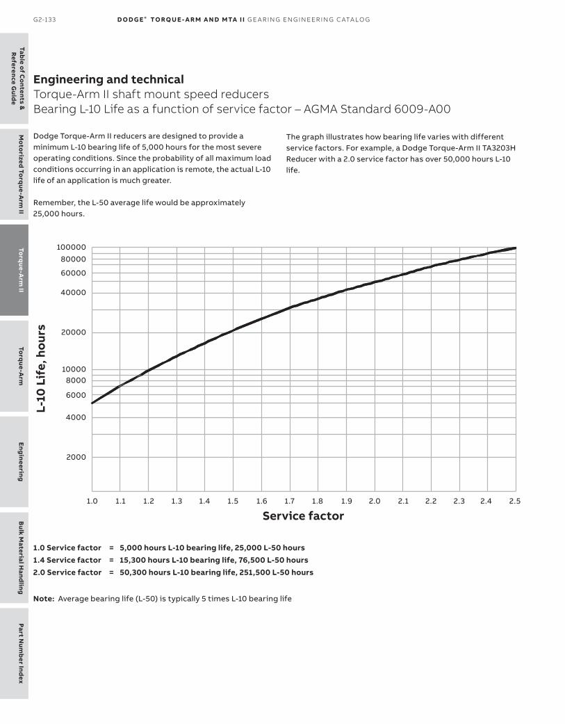
Table o
f Co
ntents &R
eference Guid
eTo
rque-A
rm II
Mo
torized To
rque-A
rm II
Torq
ue-Arm
Eng
ineeringB
ulk Material H
andling
Part Num
ber Ind
ex
G2-133 D O D G E ® TO RQ U E - A R M A N D MTA I I G E A R I N G EN G I N EER I N G C ATA LO G
Engineering and technicalTorque-Arm II shaft mount speed reducersBearing L-10 Life as a function of service factor – AGMA Standard 6009-A00
Bearing L-10 Life as a function of service factor
Dodge Torque-Arm II reducers are designed to pro vide a minimum L-10 bearing life of 5,000 hours for the most severe operating conditions. Since the probability of all maximum load conditions occurring in an application is remote, the actual L-10 life of an application is much greater.
Remember, the L-50 average life would be approximately 25,000 hours.
The graph illustrates how bearing life varies with different service factors. For example, a Dodge Torque-Arm II TA3203H Reducer with a 2.0 service factor has over 50,000 hours L-10 life.
1.0 Service factor = 5,000 hours L-10 bearing life, 25,000 L-50 hours1.4 Service factor = 15,300 hours L-10 bearing life, 76,500 L-50 hours2.0 Service factor = 50,300 hours L-10 bearing life, 251,500 L-50 hours
Note: Average bearing life (L-50) is typically 5 times L-10 bearing life

Part
Num
ber
Ind
exEn
gin
eeri
ngB
ulk
Mat
eria
l Han
dlin
gTo
rque
-Arm
To
rque
-Arm
IIM
oto
rize
d To
rque
-Arm
IITa
ble
of
Co
nten
ts &
Ref
eren
ce G
uid
e
TO R Q U E- A R M I I G2-134
— Notes

Table o
f Co
ntents &R
eference Guid
eTo
rque-A
rm II
Mo
torized To
rque-A
rm II
Torq
ue-Arm
Eng
ineeringB
ulk Material H
andling
Part Num
ber Ind
ex
G2-135 D O D G E ® TO RQ U E - A R M A N D MTA I I G E A R I N G EN G I N EER I N G C ATA LO G
— Notes