table of contents - electrocomponentes de soldadura-desoldadura... · table of contents packing...
TRANSCRIPT

TABLE OF CONTENTS
TITLE PAGE
General Information ..................................................................................................2
Introduction ..................................................................................................2
Specifications ................................................................................................3
Parts Identification ........................................................................................4
Safety ...................................................................................................................... .5
Safety Guidelines, English Language ............................................................5
Safety Guidelines, French Language .............................................................6
Safety Guidelines, German Language ............................................................7
Safety Guidelines, Italian Language ..............................................................8
Safety Guidelines, Portuguese Language ......................................................9
Safety Guidelines, Spanish Language .........................................................10
Safety Guidelines, Swedish Language .........................................................11
Set-Up ....................................................................................................................12
Tip & Tool Stand .........................................................................................12
Handpiece Vacuum/Pressure .......................................................................13
Handpiece Conntection ...............................................................................14
System Power Up ........................................................................................14
Heater Burn In .............................................................................................15
Operation ...............................................................................................................15
Temperature Selection .................................................................................15
LED Operation .............................................................................................16
Repair .....................................................................................................................17
Repair Procedure .........................................................................................17
Calibration ...................................................................................................18
Corrective Maintenance ..............................................................................19
Power Source ....................................................................................19
Handpieces .......................................................................................20
Disassembly/Assembly ...............................................................................21
Assembly Detail ..........................................................................................23
Wiring Diagram............................................................................................24
Schematic ....................................................................................................25
i
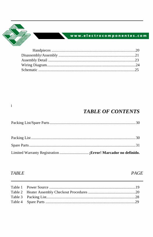
TABLE OF CONTENTS
Packing List/Spare Parts ........................................................................................ 30
Packing List ........................................................................................................... 30
Spare Parts ............................................................................................................. 31
Limited Warranty Registration .............................. ¡Error! Marcador no definido.
TABLE PAGE
Table 1 Power Source .........................................................................................19
Table 2 Heater Assembly Checkout Procedures .................................................20
Table 3 Packing List............................................................................................28
Table 4 Spare Parts .............................................................................................29

ii
PACE Incorporated retains the right to make changes to specifications contained
herein at any time, without notice.
Contact your local authorized PACE Distributor or PACE Incorporated to obtain the
latest specifications.
The following are registered trademarks and/or servicemarks of PACE
Incorporated, Laurel Maryland U.S.A. and may only be used to identify
genuine PACE products or services:
Arm-Evac, Mini-Wave, PACE, SensaTemp, Snap-Vac, Sodrtek, Sodr-
XTractor, ThermoFlo, ThermoJet, ThermoTweez, Toolnet, Visifilter.
For any questions regarding this Operation & Maintenance Manual, contact your
local authorized PACE distributor or contact PACE directly at the appropriate
address listed below.

1
MANUAL NUMBER 5050-0456
REV. C

2
General Information
Introduction
Thank you for purchasing the PACE model ST 75 Soldering/Desoldering System.
This manual will provide you with the information necessary to properly set up,
operate and maintain the ST 75 system.
The ST 75 systems are available in either the 115 VAC, or 230 VAC version which
incorporates a highly responsive SensaTemp (closed loop) control system providing
up to 80 Watts of total power to a single output channel. The 230 VAC version system
bears the CE Conformity Marking which assures the user that it conforms to all the
requirements of council directive EMC 89/336/EEC. The systems package the power
source with a selection of accessories and functional aids.
The PACE Sodr-X-Tractor handpiece provides thermally enhanced thru-hole
desoldering, safe removal of TQFP (Thin Quad FlatPack) and TSOP (Thin Small
Outline Package) surface mount components and continuous removal of old solder
from surface mount lands.
PACE SensaTemp handpieces may be used with the ST 75 system to perform a wide
variety of advanced surface mount & thru-hole component removal/replacement
operations.
General Information
Specifications
System power sources are available in either the 115 VAC or 230 VAC version.
The 230 volt system bears the Conformity Marking which assures the user that it
conforms to all the requirements of (EU) directive EMC 89/336/EEC & 73/23/EEC.
System Power Source Power Requirements:
ST 75 - Operates on 97-127 VAC, 50/60Hz
120 Watts maximum at 115 VAC, 60Hz
ST 75E - Operates on 197-253 VAC 50/60Hz
120 Watts maximum at 230 VAC, 50Hz
Temperature Specifications:
3
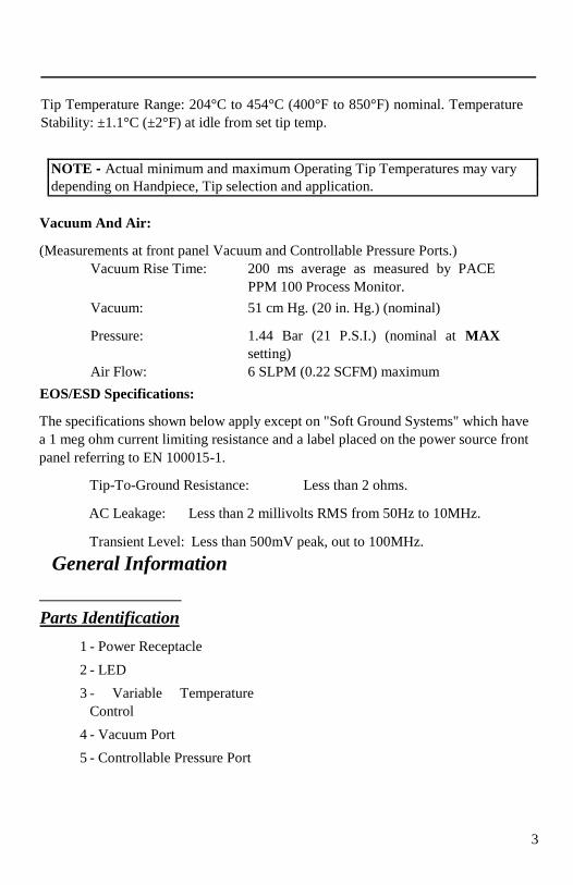
Tip Temperature Range: 204°C to 454°C (400°F to 850°F) nominal. Temperature
Stability: ±1.1°C (±2°F) at idle from set tip temp.
NOTE - Actual minimum and maximum Operating Tip Temperatures may vary
depending on Handpiece, Tip selection and application.
Vacuum And Air:
(Measurements at front panel Vacuum and Controllable Pressure Ports.)
Vacuum Rise Time: 200 ms average as measured by PACE
PPM 100 Process Monitor.
Vacuum: 51 cm Hg. (20 in. Hg.) (nominal)
Pressure: 1.44 Bar (21 P.S.I.) (nominal at MAX
setting)
Air Flow: 6 SLPM (0.22 SCFM) maximum
EOS/ESD Specifications:
The specifications shown below apply except on "Soft Ground Systems" which have
a 1 meg ohm current limiting resistance and a label placed on the power source front
panel referring to EN 100015-1.
Tip-To-Ground Resistance: Less than 2 ohms.
AC Leakage: Less than 2 millivolts RMS from 50Hz to 10MHz.
Transient Level: Less than 500mV peak, out to 100MHz.
General Information
Parts Identification
1 - Power Receptacle
2 - LED
3 - Variable Temperature
Control
4 - Vacuum Port
5 - Controllable Pressure Port

4
6 - Power Switch
7/8 - AC Power Receptacle/Fuse
Holder
9 - Earth Ground Receptacle
(230 VAC Systems
only)
Safety
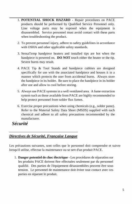
Safety Guidelines - English Language
The following are safety precautions which personnel must understand and follow
when using or servicing PACE products.
5
1. POTENTIAL SHOCK HAZARD - Repair procedures on PACE
products should be performed by Qualified Service Personnel only.
Line voltage parts may be exposed when the equipment is
disassembled. Service personnel must avoid contact with these parts
when troubleshooting the product.
2. To prevent personnel injury, adhere to safety guidelines in accordance
with OSHA and other applicable safety standards.
3. SensaTemp handpiece heaters and installed tips are hot when the
handpiece is powered on. DO NOT touch either the heater or the tip.
Severe burns may result.
4. PACE Tip & Tool Stands and handpiece cubbies are designed
specifically for use with the associated handpiece and houses it in a
manner which protects the user from accidental burns. Always store
the handpiece in its holder. Be sure to place the handpiece in its holder
after use and allow to cool before storing.
5. Always use PACE systems in a well ventilated area. A fume extraction
system such as those available from PACE are highly recommended to
help protect personnel from solder flux fumes.
6. Exercise proper precautions when using chemicals (e.g., solder paste).
Refer to the Material Safety Data Sheet (MSDS) supplied with each
chemical and adhere to all safety precautions recommended by the
manufacturer.
Sécurité
Directives de Sécurité, Française Langue
Les précautions suivantes, sont celles que le personnel doit comprendre et suivre
lorsqu'il utilise, effectue la maintenance ou se sert d'un produit PACE.
1. Danger potentiel de choc èlectrique - Les procédures de réparation sur
les produits PACE doivent être effectuées seulement par du personnel
qualifié. Des parties de l'équipement désassemblées peuvent être sous
tension. Le personnel de maintenance doit éviter tout contact avec ces
parties en réparant le produit.
6
2. Pour prévenir tout préjudice, le personnel adhère au guide de sécurité en
accord avec OSHA (équivalent à des normes françaises de sécurité) et
d'autres standards de sécurité applicable.
3. La mise sous tension des outils SensaTemp comporte des éléments
chauffants (buse). Ces derniers, gardent la chaleur même après la mise
hors tension pendant un certain temps. Ne pas toucher les parties
chaudes aux extrémités des outils. Des brûlures sévères peuvent en
résulter.
4. Les outils PACE et leurs pannes ainsi que le support sont dessinés de
manière spécifique afin de protéger l'utilisateur/opérateur de brûlures
accidentelles. Reposer toujours les outils après chaque utilisation dans
leurs étuis/supports afin de permettre leur refroidissement.
5. Utiliser toujours les stations Pace dans unlieu bien ventilé. Des
extracteurs de fumée Pace sont hautement recommandés pour protéger
votre personnel des vapeurs de soudure/flux.
6. Prenez les mesures nécessaires quand vous utilisez des produits (ex:
solder paste) chimiques. Reportez-vous au document (fiche technique/
sécurité) du fabricant fourni avec chaque produit. Respectez toutes les
procédures de sécurité recommandées par le constructeur.
Sicherheit
Sicherheit Korrekturlinien, Deutsche Sprache
Die nachfolgenden Sicherheitsvorschriften sollten vom Bedien- un Servicepersonal
verstanden und befolgt werden.
1. Entladung spannungsfuehrender Teile - Reparaturen an PACE
Produkten sollten nur von qualifizierten Personal durchgefuehrt werden.
Spannungsfuehrende Teile koennen sich bei gezogenen Netzstecker
entladen. Servicepersonal muss den Kontakt dieser Teile vermeiden.
2. Um moegliche Gefahren fuer Personen auszuschliessen, muessen alle
Sicherheitsvorschriften in Uebereinstimmung mit OSHA und anderen
anwendbaren Sicherheitsstandards eingehalten werden.
7
3. Angeschlossene SensaTemp Heizelemente von Handwerkzeugen und
installierte Loetspitzen sind heiss wenn das System eingeschaltet ist oder
erst vor kurzer Zeit ausgeschaltet wurde. Heizelement und Loetspitze
nicht beruehren. Verbrennungsgefahr.
4. PACE Tip & Tool und andere Handwerkzeugablagen sind so konstruiert,
dass ein versehentliches Beruehren des dazugehoerendes
Handwerkzeuges vermieden wird. Bewahren Sie das Handwerkzeug
nach Gebrauch stets in der Ablage auf. Bevor das Handwerkzeug an
einem anderen Ort gelagert werden muss, lassen Sie es in der
Werkzeugablage vollstaendig abkuehlen.
5. Benutze PACE Systeme nur in gut beluefteten Raeumen. Ein
Loetrauchabsaugsystem, wie es z.B. von PACE erhaeltlich ist, hilft
Bedienpersonen von den Gefahren von Loetrauch zu schuetzen.
6. Wenn Chemikalien (z.B.: Lotpaste) verwendet werden, muessen alle die
in den Sicherheitsdatenblaettern des Herstellers ausgewiesenen
Sicherheitsvorschriften eingehalten werden.
Sicurezza
Misure di Sicurezza, Italiana Lingua
Le seguenti instruzioni sono misure di sicurezza che il personale deve comprendere
e seguire quando utilizza o ripara I prodotti PACE.
1. EVENTUALI RISCHI DI SHOCK ELETTRICO- Si consiglia di far
eseguire le operazioni di riparazione dei prodotti PACE, da un servizio
di personale qualificato. Quando la stazione non é assemblata le parti
sottoposte alla tensione di linea potrebbero essere scoperte. Il personale
deve evitare il contatto con queste parti durante manutenzione del
prodotto.
2. Per evitare eventuali pericoli al personale, attenersi alle norme di
sicurezza previste dalla guida, in conformitá all’OSHA e agli altri
Standard di Sicurezza applicabili.
8
3. Le resistenze PACE Sensatemp e le punte installate sono calde quando la
stazione é accesa e per un periodo successivo allo spegnimento. Non
toccare la resistenza e la punta. Puó comportare gravi ustioni.
4. I supporti PACE sono specificamente costruiti insieme alla
corrispondente impugnatura e progettati per un uso che protegge gli utenti
da ustioni accidentali. Mettere sempre l’impugnatura nel propio supporto
dopo l’utilizzo e lasciarla raffredare prima di riporla.
5. Utilizzare sempre I stazioni PACE in una zona be aerata per proteggere il
personale dai fumi. É fortemente raccomandato un sistema di aspirazione
(dei fumi) come quello disposta dalla PACE.
6. Usare precauzioni quando si utilizzano sotanze chimiche (es. Pasta di
stagno). Fare riferimento al Material Safety Data Sheet (MSDS) fornita
con ogni sostanza chimica e seguire tutte le misure di sicurezza
raccomandate dal fabbricante.
Segurança
Guidelines de Segurança, Portuguese Lingua
Segeum-se precauções de segurança que os operadores devem compreender e seguir
ao utilizar ou reparar produtos PACE.
1. Perigo de choque eléctrico - Os procedimentos de reparação em produtos
PACE, devem ser apenas efectuados por pessoal qualificado. Linhas de
alimentação podem ficar expostas ao desmontar o equipamento. Pessoal
de reparação deve evitar o contacto com essas partes ao reparar o produto.
2. Para evitar danos pessoais, siga as normas de segurança OSHA ou outras
normas aplicáveis.
3. Resistencias de aquecimento dos ferros e as pontas instaladas estão
quentesquando o ferro está alimentado, e mesmo durante algum tempo
após ser desligado. NUNCA TOCAR nem na resistencia de
aquecimento nem na ponta. Pode resultar em queimaduras severas.
4. Os suportes para pontas e ferros da PACE, foram concebidos para uso
especifico, e para proteger o operador de queimaduras acidentais. Coloque
sempre os ferros nos respectivos suportes. Tenha a certeza de colocar
9
sempre o ferro no respectivo suporte após cada utilização e deixeo
arrefecer antes de o guardar.
5. Utilize sempre os sistemas da PACE em locais bem ventilados. Um
Sistema de extracção de fumos, como os Sistemas disponiveis na PACE,
são altamente recomendados para a protecção dos utilizadores contra os
fumos produzidos pela solda e fluxo.
6. Tenha precauções apropriadas ao utilizar produtos quimicos (ex. pasta de
soldar). Lêr sempre atentamente os normas de segurança fornecidas com
cada produto químico e siga sempre todas as precauções de segurança
recomendadas pelo fabricante.
Seguridad
Guias de Consulta de Seguridad, Espãnol Lenguaje
Lo siguiente es precauciones de seguridad que el personal debe entender y debe
seguir al usar o reparar productos de PACE.
1. RIESGO de SHOCK POTENCIAL - Los procedimientos de la
Reparación en productos de PACE sólo deben ser realizados por Personal
de Servicio Calificado. Pueden exponerse partes de voltaje de línea cuando
el equipo se desmonta. El personal de servicio debe evitar contacto con
estas partes al arreglar el producto.
2. Para prevenir lesión del personal, adhiera a las reglas de seguridad de
acuerdo con OSHA y otras normas de seguridad aplicables.
3. Las herramientas SensaTemp tienen sus calentadores y las puntas
instaladas calientes cuando la herramienta esta encendida y por un periodo
de tiempo después de apagar el equipo. No toque el calentador o la
punta. Las quemaduras severas pueden resultar.
4. El Soporte de punta y Herramienta PACE se diseñan específicamente para
el uso con las herramientas asociadas y las almacena de una manera que
protege al usuario de las quemaduras accidentales. Siempre guarde la
herramienta en su soporte. Esté seguro de poner la herramienta en su
soporte después del uso y permita que la herramienta enfríe antes de
guardar.

10
5. Siempre use sistemas de PACE en una área bien ventilada. Un sistema de
extraccíon de humo como esos disponibles de PACE se recomiendan para
ayudar a protejer al personal contra los humos de flujo de soldadura.
6. Ejercicie las precauciones apropiadas al usar químicos (ej., pasta de la
soldadura). Refiérase a la Hoja de Datos de Seguridad de Material (MSDS)
proporcionadó con cada químico y adhiere a todas las precauciones de
seguridad recomendadas por el fabricante.
Säkerhetsföreskrifter
Säkerhetsföreskrifter, Svenska
Följande säkerhetsföreskrifter måste förstås och följas av personal som använder eller
utför service på PACE produkter.
1. RISK FÖR STRÖMSTÖT - Service / Reparation av PACE produkter får
endast utföras av aktoriserad service personal. Strömförande delar kan
kommas åt när produkten är isärplockad. Iaktag aksamhet när felsökning
görs för att undvika strömstötar.
2. För att undvika personskada rekommenderas att OSHA eller andra
liknande arbetssäkerhets standarder följs.
3. SensaTemp verktygselement och installerade spetsar är heta när strömmen
är påslagen och en tid efter att strömmen slagits av. RÖR EJ element eller
spets. Risk för brännskador!
4. PACE Spets och Verktygshållare är speciellt utformade för att passa PACE
respektive verktyg så att risken för brännskador kan undvikas. När
verktyget ej används bör det alltid förvaras i sin hållare.
5. Tillse att ventilationen är god där PACE System används. Ett lödröksutsug
system som t.ex. PACE tillhandahåller rekommenderas för att skydda
användaren för giftig lödrök.
6. Tillse att gällande säkerhetsföreskrifter följs vid användning av kemikalier,
t.ex. lodpasta.Se säkerhetsdatabladen som medföljer kemikalierna och följ
de rekommenderade säkerhetsföreskrifterna från respektive tillverkare.
11
Set-Up
Tip & Tool Stand
If you have purchased a system with a handpiece, set up the Tip & Tool Stand in the
following manner. Set up any other SensaTemp handpiece, use the instructions
enclosed with the handpiece and associated Tip & Tool Stand.
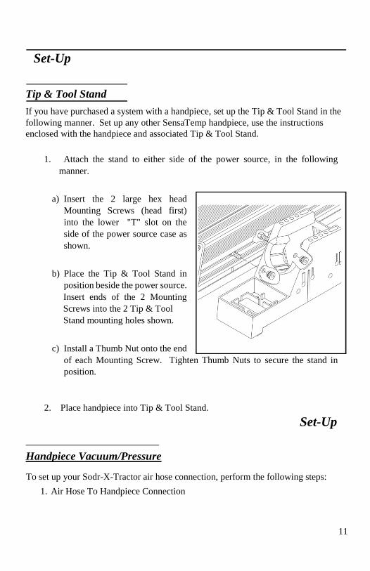
1. Attach the stand to either side of the power source, in the following
manner.
a) Insert the 2 large hex head
Mounting Screws (head first)
into the lower "T" slot on the
side of the power source case as
shown.
b) Place the Tip & Tool Stand in
position beside the power source.
Insert ends of the 2 Mounting
Screws into the 2 Tip & Tool
Stand mounting holes shown.
c) Install a Thumb Nut onto the end
of each Mounting Screw. Tighten Thumb Nuts to secure the stand in
position.
2. Place handpiece into Tip & Tool Stand.
Set-Up
Handpiece Vacuum/Pressure
To set up your Sodr-X-Tractor air hose connection, perform the following steps:
1. Air Hose To Handpiece Connection

12
a) Attach one end of a 137cm (54 inch) length of air hose to the metal tube
in the back of the handpiece.
b) If you have a PACE system incorporating only one handpiece, attach the
air hose to the power cable using the supplied Hose Clamps. Space them
evenly along the length of the power cable starting at a point 6 inches
from the ends of the handpiece.
c) If you have a PACE system incorporating 2 or more air handpieces, you
may wish to leave the air hose assembly unattached to allow a quick
change to any air handpiece being used.
2. Prepare a VisiFilter in the following manner:
a) Connect a 1 inch (2.5cm) length of clear
pvc air hose to the FLOW OUT side of the
VisiFilter; push and turn the hose onto the
VisiFilter nipple to seat.
b) Insert the ribbed end of a male quick
connect hose mount fitting (P/N 1259-
0087) into the free end of the 1 inch (2.5cm)
length of air hose connected to the FLOW
OUT side of the
VisiFilter.
c) Connect the free end of the 137cm (54 inch)
length of air hose to the FLOW IN side of
the VisiFilter.
d) Insert the end of the quick connect hose
mount fitting (on VisiFilter FLOW OUT
side) into the power source Vacuum Port.
3. When using air pressure, and/or utilizing multiple air handpieces, PACE
recommends the use of the following set up procedure which utilizes
additional quick connect hose mount fittings. An assortment of quick connect
air fittings are supplied with each additional air handpiece.
a) Disconnect the 137cm (54 inch) length of air hose from the FLOW IN
side of the VisiFilter assembly. Insert the ribbed end of a male quick
connect hose mount fitting (P/N 1259-0087) into the free end of this air
hose.
Set-Up
13
b) Connect the free end of a 1 inch (2.5cm) length of air hose with an
installed female quick connect hose mount fitting (P/N 1259-0086) to
the FLOW IN side of the VisiFilter Assembly.
c) The 137cm (54 inch) length of air hose can now be easily moved
between the VisiFilter Assembly and the Controllable Pressure Port. The
VisiFilter assembly remains connected to the Vacuum Port.
4. Additional fittings may also be added to the hose connection at the rear of
each air handpiece to ease changing of handpieces.
NOTE
When removing any air hose, turn and pull. Do not attempt to pull hose directly
off. Damage to or breakage of fitting or VisiFilter may occur. Use your Sodr-X-
Tractor with a clean VisiFilter element. Otherwise a deterioration in performance
or damage to the unit may occur.
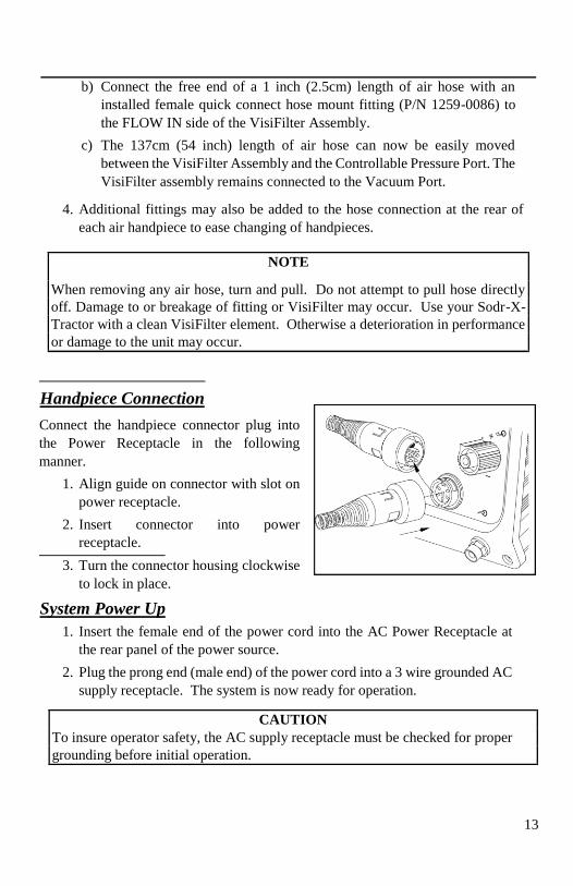
Handpiece Connection
Connect the handpiece connector plug into
the Power Receptacle in the following
manner.
1. Align guide on connector with slot on
power receptacle.
2. Insert connector into power
receptacle.
3. Turn the connector housing clockwise
to lock in place.
System Power Up
1. Insert the female end of the power cord into the AC Power Receptacle at
the rear panel of the power source.
2. Plug the prong end (male end) of the power cord into a 3 wire grounded AC
supply receptacle. The system is now ready for operation.
CAUTION
To insure operator safety, the AC supply receptacle must be checked for proper
grounding before initial operation.
14
3. Read this manual and all other included manuals thoroughly before
operating the system.
Set-Up/Operation
Heater Burn In
To insure optimum performance and long life, new TJ-70 handpieces must undergo
a burn in procedure. A Red tag is attached to each handpiece and with replacement
heater assemblies which describes the proper procedure. Perform the procedure
listed on the tag when setting up a new ST 75 system or when replacing a TJ-70
heater assembly.
NOTE
Ensure that the system is placed in a well-ventilated area. Smoke will be emitted
from the heater assembly during the burn in cycle.
Temperature Selection
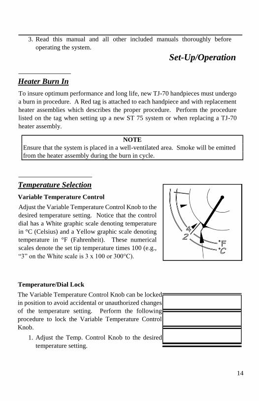
Variable Temperature Control
Adjust the Variable Temperature Control Knob to the
desired temperature setting. Notice that the control
dial has a White graphic scale denoting temperature
in °C (Celsius) and a Yellow graphic scale denoting
temperature in °F (Fahrenheit). These numerical
scales denote the set tip temperature times 100 (e.g.,
“3” on the White scale is 3 x 100 or 300°C).
Temperature/Dial Lock
The Variable Temperature Control Knob can be locked
in position to avoid accidental or unauthorized changes
of the temperature setting. Perform the following
procedure to lock the Variable Temperature Control
Knob.
1. Adjust the Temp. Control Knob to the desired
temperature setting.
15
2. Using the Temp. Locking Key (hex key supplied
with system), tighten the set screw on the
Temperature Control Knob closest to the front
panel.
Operation
Tip Offset
Differences between the temperature settings and true
tip temperatures are negligible when using Thru-Hole,
single point soldering tips. With any heating system
however, True Tip Temperatures can differ greatly
from temperature settings when using larger SMT
soldering tips. This difference is called Tip
Temperature Offset. PACE recommends the use of the
Tip & Temperature Selection System booklet (PACE
P/N 5050-0251) as a guide to accurately set and
maintain a true tip temperature for any size and type of
SMT tip.
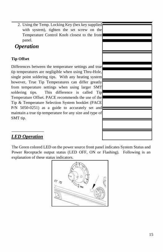
LED Operation
The Green colored LED on the power source front panel indicates System Status and
Power Receptacle output status (LED OFF, ON or Flashing). Following is an
explanation of these status indicators.

16
LED Full On - Continuous power is being delivered to the handpiece. This condition
is evident when the system is first powered up (handpiece heater cold) or the Variable
Temperature Control setting is increased.
LED Flashing - Indicates that the set tip temperature (as set on the Variable
Temperature Control) has been reached. Power to the handpiece is cycling Off and
On to maintain set temperature.
LED Off - No power is being delivered to the handpiece heater. This condition is
evident for a short period of time when set temperature is reached and stabilizing or
if the Variable Temperature Control setting is decreased. If the LED never
illuminates, check for a faulty handpiece (see Corrective Maintenance section). Also,
if no handpiece is connected to the power source, the LED will not illuminate.
Repair
17
Repair Procedure
The "Repair" section of this manual provides the technician with the information
necessary to determine the source of a malfunction and take the necessary steps to
correct it. In order to perform the most expedient repair, the technician must follow
the process listed below step by step, in order. Failure to do so will make the
diagnosis and repair much more difficult.
1. Periodic Maintenance - Required on any PACE handpiece used. Refer
to the the "Handpiece Operation" portion of this manual for specific
instructions. No periodic or special maintenance is required on the power
source.
2. Calibration - The system can be easily checked to verify temperature
accuracy. No internal adjustments can be made.
3. Corrective Maintenance - A guide for resolving minor malfunctions.
Locate the "Symptom" in the Corrective Maintenance Table (Power
Source or Heater Assembly Checkout table) which best describes the
malfunction. Check each point described under "Solution" in order of
listing.
4. Disassembly/Assembly - Contains simple instructions which enable the
technician to open/close the unit for servicing.
5. Repair Drawings - Exploded power source, wiring diagram and
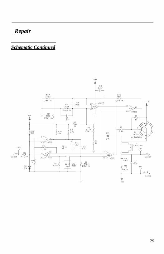
schematic are included as aides in troubleshooting and repair.
6. PACE Service Department - If the cause for malfunction has not been
determined at this point, call the PACE Service Department at 1-(888)535-
PACE (toll free) or FAX (301)483-7030.
Repair
Calibration
The ST 75 system is tested for temperature accuracy at the factory and can be checked
for calibration according to PACE requirements. Also, a temperature setting
Repair
18
normally used by the operator can be adjusted to the precise temperature indicated on
the Dial/Display. No internal adjustments can be made to the power supply. To
verify calibration of the power supply, perform the following procedure.
1. Install a tip with an attached thermocouple wire into the handpiece connected
to the system. Tips with K type thermocouples are available from PACE; use
part number 7021-0004-P1 when ordering.
2. Connect the thermocouple assembly to a PACE Process Monitor (part number
8001-0077 or 8001-0078) or appropriate temperature meter.
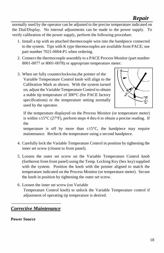
3. When set fully counterclockwise,the pointer of the
Variable Temperature Control knob will align to the
Calibration Mark as shown. With the system turned
on, adjust the Variable Temperature Control to obtain
a stable tip temperature of 300°C (for PACE factory
specifications) or the temperature setting normally
used by the operator.
If the temperature displayed on the Process Monitor (or temperature meter)
is within ±15°C (27°F), perform steps 4 thru 6 to obtain a precise reading. If
the
temperature is off by more than ±15°C, the handpiece may require
maintenance. Recheck the temperature using a second handpiece.
4. Carefully lock the Variable Temperature Control in position by tightening the
inner set screw (closest to front panel).
5. Loosen the outer set screw on the Variable Temperature Control knob
(furtherest from front panel) using the Temp. Locking Key (hex key) supplied
with the system. Position the knob with the pointer aligned to match the
temperature indicated on the Process Monitor (or temperature meter). Secure
the knob in position by tightening the outer set screw.
6. Loosen the inner set screw (on Variable
Temperature Control knob) to unlock the Variable Temperature control if
adjustment of operating tip temperature is desired.
Corrective Maintenance
Power Source

Repair
19
Most malfunctions are simple and easy to correct. Refer
to Table 1 below to clear these malfunctions.
Symptom Probable Cause Solution
No power to system. Blown Fuse Check handpiece using "Heater Assembly Checkout Procedures",
Table 4. Replace fuse located in
AC Receptacle/Fuse Holder.
Insufficient vacuum or air
pressure. Motor Pump runs.
Handpiece air hose has a
kink or hole in hose. Check handpiece hose. Replace
air hose if necessary
VisiFilter or handpiece filter
clogged. Replace VisiFilter or handpiece
filter.
Handpiece chamber not
seated properly in
handpiece.
Check handpiece. Reseat
chamber if necessary.
Defective Motor Pump
Assembly. Check vacuum and air pressure at
Motor Pump Assembly air hose
connections. Replace Motor Pump Assembly if necessary.
No vacuum or air pressure.
Motor Pump does not run. Defective handpiece. Check handpiece using "Heater
Assembly Checkout Procedures",
Table 4.

Repair
20
Defective Motor Pump
Assembly. Check for 12 VDC at motor
terminals with handpiece switch
actuated. Replace Motor Pump
Assembly if defective.
Defective Main PCB
Assembly If there is no 12 VDC at Motor
Pump Assembly, repair or replace
Main PCB Assembly.
No heat on handpiece. Defective Heater Refer to "Heater Assembly Checkout Procedures", Table 4.
Table 1. Power Source Corrective Maintenance
Repair
Handpieces
The following “Heater Assembly Checkout Procedures” (Table 2) is applicable to all
PACE SensaTemp handpieces used with the ST 75 system except for the TT65 and
DTP-80handpieces. Refer to the applicable manuals for troubleshooting procedures
pertinent to that handpiece. Perform the procedures with the handpiece heater at room
temperature. If the heater is warm, resistance readings will be different from those
shown. Disconnect the handpiece from the power source. Use a meter to check
resistance across the handpiece connector plug pins as outlined in the “Checkout
Procedure” column.
Symptom Checkout Procedure Cause Solution
Handpiece
does not heat. Check resistance - Pin 2 to
Pin 5. Refer to "Heater
Specifications" column. If resistance is high - -
Open Heater Replace Heater
Assembly.
Check resistance - Pin 3 to Pin 6. If circuit reads open -
Open Sensor Replace Heater
Assembly.
Handpiece
overheating. Check resistance - Pin 3 to Pin 6. Resistance should be
110 ohms. If resistance is
less than 105 ohms - -
Shorted
Sensor Replace Heater
Assembly.
Fuse blows
when unit
is turned
on.
Check resistance - Pin 2 to Pin 5. Refer to "Heater
Specifications" column.
If resistance is low - -
Shorted
Heater Replace Heater
Assembly & Fuse.
Repair
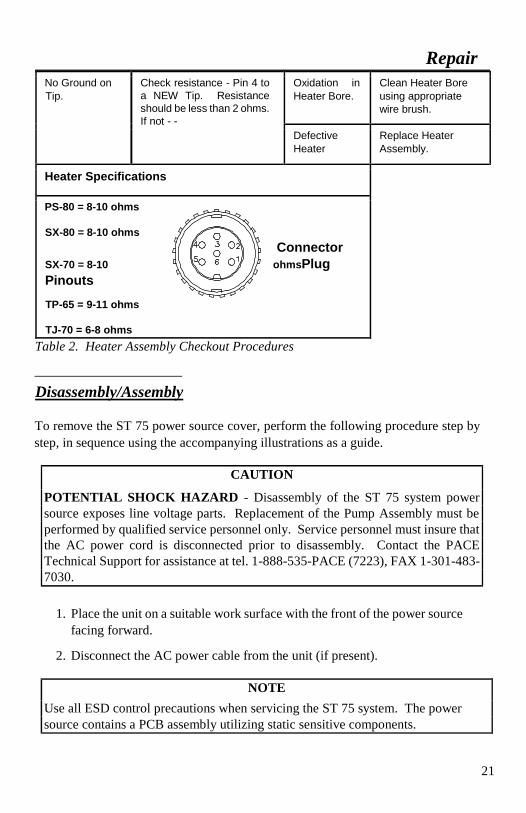
21
No Ground on Tip.
Check resistance - Pin 4 to
a NEW Tip. Resistance
should be less than 2 ohms. If not - -
Oxidation in
Heater Bore. Clean Heater Bore
using appropriate
wire brush.
Defective
Heater Replace Heater
Assembly.
Heater Specifications
PS-80 = 8-10 ohms
SX-80 = 8-10 ohms
Connector
ohmsPlug SX-70 = 8-10
Pinouts
TP-65 = 9-11 ohms
TJ-70 = 6-8 ohms
Table 2. Heater Assembly Checkout Procedures
Disassembly/Assembly
To remove the ST 75 power source cover, perform the following procedure step by
step, in sequence using the accompanying illustrations as a guide.
CAUTION
POTENTIAL SHOCK HAZARD - Disassembly of the ST 75 system power
source exposes line voltage parts. Replacement of the Pump Assembly must be
performed by qualified service personnel only. Service personnel must insure that
the AC power cord is disconnected prior to disassembly. Contact the PACE
Technical Support for assistance at tel. 1-888-535-PACE (7223), FAX 1-301-483-
7030.
1. Place the unit on a suitable work surface with the front of the power source
facing forward.
2. Disconnect the AC power cable from the unit (if present).
NOTE
Use all ESD control precautions when servicing the ST 75 system. The power
source contains a PCB assembly utilizing static sensitive components.

Repair
22
NOTE
At this point, you may wish to remove any accessories attached to the
power source to ease removal of the 2 Cover Mounting Screws (step
6).
3. Remove the 4 Front Panel
mounting screws located
at each corner of the Front
Panel Bezel.
4. Pull the Front Panel and
Bezel forward.
Repair
5. Remove the 3 upper Rear
Panel mounting screws.
6. Reposition the unit with
the rear of the power
source facing forward.
7. A Cover Mounting Screw
is located on each side of
the power source
(positioned bottom center). Remove the 2 Cover Mounting Screws.
8. Lift the Cover from the power source. Set Cover aside.
Repair
23
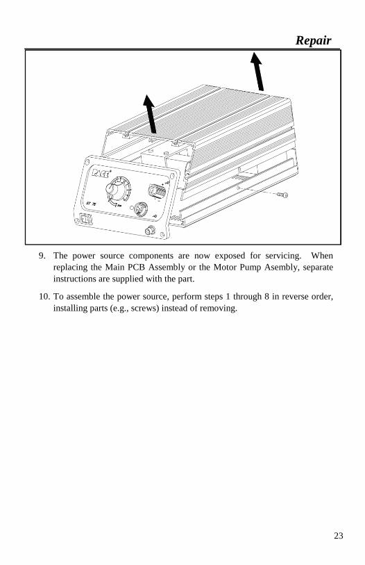
9. The power source components are now exposed for servicing. When
replacing the Main PCB Assembly or the Motor Pump Asembly, separate
instructions are supplied with the part.
10. To assemble the power source, perform steps 1 through 8 in reverse order,
installing parts (e.g., screws) instead of removing.

24
Assembly Detail
Rear Panel
Motor Pump Assembly
Front Panel
Repair

25

26
Repair
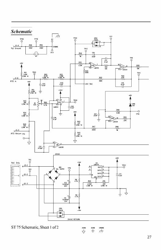
27

28
Repair
29
Repair
Schematic Continued
30
ST 75 Schematic, Sheet 2 of 2
Packing List/Spare Parts
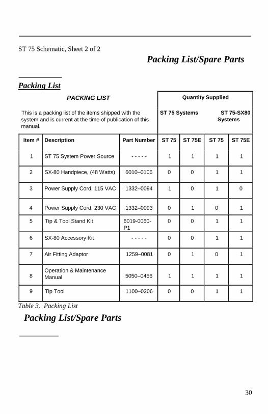
Packing List
PACKING LIST Quantity Supplied
This is a packing list of the items shipped with the
system and is current at the time of publication of this
manual.
ST 75 Systems ST 75-SX80 Systems
Item # Description Part Number ST 75 ST 75E ST 75 ST 75E
1 ST 75 System Power Source - - - - - 1 1 1 1
2 SX-80 Handpiece, (48 Watts) 6010–0106 0 0 1 1
3 Power Supply Cord, 115 VAC 1332–0094 1 0 1 0
4 Power Supply Cord, 230 VAC 1332–0093 0 1 0 1
5 Tip & Tool Stand Kit 6019-0060-
P1 0 0 1 1
6 SX-80 Accessory Kit - - - - - 0 0 1 1
7 Air Fitting Adaptor 1259–0081 0 1 0 1
8 Operation & Maintenance
Manual 5050–0456 1 1 1 1
9 Tip Tool 1100–0206 0 0 1 1
Table 3. Packing List
Packing List/Spare Parts

31
Spare Parts