table of contents end-wheel, no-till drill
TRANSCRIPT

Table of Contents
End-Wheel, No-Till Drill
706/1006NTRead the Operator’s Manual entirely. When you see this symbol,the subsequent instructions and warnings are serious - followwithout exception. Your life and the lives of others depend on it!
Cover photo may show optional equipment not suppliedwith standard unit.For an Operator’s Manual and Decal Kit in anotherlanguage, please see your Land Pride dealer.
Printed 2018-06-12
313-855MOperator Manual

Machine IdentificationRecord your machine details in the log below. If you replace this manual, be sure to transfer this information to the newmanual.
If you or the dealer have added options not originally ordered with the machine, or removed options that were originallyordered, the weights and measurements are no longer accurate for your machine. Update the record by adding themachine weight and measurements with the option(s) weight and measurements.
Dealer Contact Information
Model Number
Serial Number
Machine Height
Machine Length
Machine Width
Machine Weight
Year of Construction
Delivery Date
First Operation
Accessories
Name:
Street:
City/State:
Telephone:
Email:
Dealer’s Customer No.:
WARNING: Cancer and Reproductive Harm - www.P65Warnings.ca.gov

Table of Contents Table of Contents
Section 1: Important Safety Information . . . . . . . . . . 1Safety Decals . . . . . . . . . . . . . . . . . . . . . . . . . . . . . 5
Section 2: Introduction . . . . . . . . . . . . . . . . . . . . . . . 11Description of Unit . . . . . . . . . . . . . . . . . . . . . . . . 11Intended Usage . . . . . . . . . . . . . . . . . . . . . . . . . . 11
Models Covered . . . . . . . . . . . . . . . . . . . . . . . 11Using This Manual . . . . . . . . . . . . . . . . . . . . . . . . 11Owner Assistance. . . . . . . . . . . . . . . . . . . . . . . . . 12Further Assistance . . . . . . . . . . . . . . . . . . . . . . . . 12
Section 3: Preparation and Setup . . . . . . . . . . . . . . 13Pre-start Checklist. . . . . . . . . . . . . . . . . . . . . . . . . 13Hitching Tractor to Drill . . . . . . . . . . . . . . . . . . . . . 13
Hitch Assembly. . . . . . . . . . . . . . . . . . . . . . . . 13Hitch Height . . . . . . . . . . . . . . . . . . . . . . . . . . 14Hitching to Tractor . . . . . . . . . . . . . . . . . . . . . 14
Hydraulic Hose Hookup . . . . . . . . . . . . . . . . . . . . 15Rephasing Cylinders. . . . . . . . . . . . . . . . . . . . . . . 15Bleeding Hydraulics . . . . . . . . . . . . . . . . . . . . . . . 16Leveling Drill . . . . . . . . . . . . . . . . . . . . . . . . . . . . . 17
Section 4: Operating Instructions . . . . . . . . . . . . . . 18Pre-start Checklist. . . . . . . . . . . . . . . . . . . . . . . . . 18Field Operation . . . . . . . . . . . . . . . . . . . . . . . . . . . 18
Opener Operation. . . . . . . . . . . . . . . . . . . . . . 19Transporting . . . . . . . . . . . . . . . . . . . . . . . . . . . . . 19
Cylinder Locks . . . . . . . . . . . . . . . . . . . . . . . . 19Unload Drill Box . . . . . . . . . . . . . . . . . . . . . . . 19Clearance . . . . . . . . . . . . . . . . . . . . . . . . . . . . 19Road Rules. . . . . . . . . . . . . . . . . . . . . . . . . . . 19Lock-out Hub . . . . . . . . . . . . . . . . . . . . . . . . . 20
Parking and Unhitching. . . . . . . . . . . . . . . . . . . . . 20
Section 5: Adjustments . . . . . . . . . . . . . . . . . . . . . . 21Coulter Adjustments . . . . . . . . . . . . . . . . . . . . . . . 21
Coulter Depth Control . . . . . . . . . . . . . . . . . . 21Coulter Down Pressure . . . . . . . . . . . . . . . . . . . . 22Opener Adjustments. . . . . . . . . . . . . . . . . . . . . . . 23Opener Seeding Depth. . . . . . . . . . . . . . . . . . . . . 23Gauge Wheel Idler Adjustment. . . . . . . . . . . . . . . 24Drive Clutch . . . . . . . . . . . . . . . . . . . . . . . . . . . . . 24Drive Train Operation . . . . . . . . . . . . . . . . . . . . . . 25Spring Tine Harrow. . . . . . . . . . . . . . . . . . . . . . . . 26
Section 6: Troubleshooting . . . . . . . . . . . . . . . . . . . 27Section 7: Maintenance and Lubrication . . . . . . . . 30
Maintenance. . . . . . . . . . . . . . . . . . . . . . . . . . . . . 30Storage. . . . . . . . . . . . . . . . . . . . . . . . . . . . . . . . . 30Lubrication and Scheduled Maintenance . . . . . . . 31
Section 8: Options . . . . . . . . . . . . . . . . . . . . . . . . . . 35Section 9: Appendix . . . . . . . . . . . . . . . . . . . . . . . . . 38
Torque Values Chart . . . . . . . . . . . . . . . . . . . . . . 38Tire Inflation Chart . . . . . . . . . . . . . . . . . . . . . . . . 38Specifications and Capacities. . . . . . . . . . . . . . . . 39Hydraulic Schematic. . . . . . . . . . . . . . . . . . . . . . . 40Sprocket Configuration. . . . . . . . . . . . . . . . . . . . . 41
Seed Box . . . . . . . . . . . . . . . . . . . . . . . . . . . . 41Seed Box Agitator . . . . . . . . . . . . . . . . . . . . . 41Dual Seed Box . . . . . . . . . . . . . . . . . . . . . . . 42Small Grass Seeds . . . . . . . . . . . . . . . . . . . . 42Native Grass . . . . . . . . . . . . . . . . . . . . . . . . . 43Fertilizer . . . . . . . . . . . . . . . . . . . . . . . . . . . . 43Fertilizer with Small Grass Seeds Box. . . . . . 44
2018-06-12 706/1006NT 313-855M
© Copyright 2018 All rights Reserved
Land Pride provides this publication “as is” without warranty of any kind, either expressed or implied. While every precaution has been taken in the preparation of thismanual, Land Pride assumes no responsibility for errors or omissions. Neither is any liability assumed for damages resulting from the use of the information containedherein. Land Pride reserves the right to revise and improve its products as it sees fit. This publication describes the state of this product at the time of its publication, andmay not reflect the product in the future.
Land Pride is a registered trademark.
All other brands and product names are trademarks or registered trademarks of their respective holders.
Printed in the United States of America.

Table of Contents
Parts Manual QR LocatorThe QR Code® (Quick Reference) on the front cover and to the left will take you to the Parts Manual for this equipment. Download the appropriate App on your smart phone, open the App, point your phone on the QR Code®and take a picture.
Dealer QR LocatorThe QR Code® at left will link you to available dealers for Land Pride products. Refer to Parts Manual QR Locator for detailed instructions.
706/1006NT 313-855M 2018-06-12iv

Important Safety Information Table of Contents
Important Safety Information
Look for Safety SymbolThe SAFETY ALERT SYMBOL indicates there is a potential hazard to personal safety involved and extra safety precaution must be taken. When you see this symbol, be alert and carefully read the message that follows it. In addition to design and configuration of equipment, hazard control and accident prevention are dependent upon the awareness, concern, prudence and proper training of personnel involved in the operation, transport, maintenance and storage of equipment.
Be Aware of Signal WordsSignal words designate a degree or level of hazard seriousness.
DANGER, and the color Safety Red, indicate an imminent hazard which, if not avoided, will result in death or serious injury. This signal word is limited to the most extreme situations, typically for machine components that, for functional purposes, cannot be guarded.
WARNING, and the color Safety Orange, indicate a potential hazard which, if not avoided, could result in death or serious injury, and includes hazards that are exposed when guards are removed. It may also be used to alert against unsafe practices.
CAUTION, and the color Safety Yellow, indicate a potential hazard which, if not avoided, may result in minor or moderate injury. It may also be used to alert against unsafe practices.
Prepare for Emergencies Be prepared if a fire starts
Keep a first aid kit and fire extinguisher handy.
Keep emergency numbers for doctor, ambulance, hospitaland fire department near phone.
Be Familiar with Safety Decals Read and understand “Safety Decals” on page 5,
thoroughly.
Read all instructions noted on the decals.
Keep decals clean.Replacedamaged, fading, and illegibledecals.
Keep decals clean. Replace damaged, faded and illegibledecals.
2018-06-12 706/1006NT 313-855M 1
Important Safety Information Table of Contents
Wear Protective Equipment Wear protective clothing and equipment.
Wear clothing and equipment appropriate for the job.Avoid loose-fitting clothing.
Because prolonged exposure to loud noise can causehearing impairment or hearing loss, wear suitablehearing protection such as earmuffs or earplugs.
Because operating equipment safely requires your fullattention, avoid wearing entertainment headphones whileoperating machinery.
Handle Chemicals ProperlyAgricultural chemicals can be dangerous. Improper use can seriously injure persons, animals, plants, soil and property.
Do not use liquid seed treatments with the drill.
Read and follow chemical manufacturer’s instructions.
Wear protective clothing.
Handle all chemicals with care.
Avoid inhaling smoke from any type of chemical fire.
Never drain, rinse or wash dispensers within 100 feet(30m) of a freshwater source, nor at a car wash.
Store or dispose of unused chemicals as specified bychemical manufacturer.
Dispose of empty chemical containers properly. Lawsgenerally require power rinsing or rinsing three times,followed by perforation of the container to prevent re-use.
Avoid High Pressure FluidsEscaping fluid under pressure can penetrate the skin, causing serious injury.
Avoid the hazard by relieving pressure beforedisconnecting hydraulic lines.
Use a piece of paper or cardboard, NOT BODY PARTS, tocheck for suspected leaks.
Wear protective gloves and safety glasses or goggles whenworking with hydraulic systems.
If an accident occurs, seek immediate medical attentionfrom a physician familiar with this type of injury.
Keep Riders Off MachineryRiders obstruct the operator’s view. Riders could be struck by foreign objects or thrown from the machine.
Never allow children to operate equipment.
Keep all bystanders away from machine during operation.
706/1006NT 313-855M 2018-06-122

Important Safety Information Table of Contents
Use Safety Lights and DevicesSlow-moving tractors and towed implements can create a hazard when driven on public roads. They are difficult to see, especially at night.
Use flashing warning lights and turn signals wheneverdriving on public roads.
Use lights and devices provided with implement
Transport Machinery SafelyMaximum transport speed for implement is 20 mph (30 kph). Some rough terrains require a slower speed. Sudden braking can cause a towed load to swerve and upset.
Do not exceed 20 mph (30 kph). Never travel at a speedwhich does not allow adequate control of steering andstopping. Reduce speed if drill is not equipped withbrakes.
Comply with state and local laws.
Carry reflectors or flags to mark drill in case ofbreakdown on the road.
Semi-mounted and 3-point implements reduce weight onsteering tires. Verify that tractor is correctly ballasted. Watch for signs of poor steering traction.
Tires Not a StepDo not use gauge wheel or lift-assist tires as steps. A tire could spin underfoot, resulting in a fall onto the implement or ground, possibly causing serious injury.
The gauge wheel tires can be in poor ground contact atany time, even with the drill lowered in the field. They canappear to be in ground contact, and spin easily, inmultiple conditions.
The lift-assist tires can be in poor ground contact, or outof ground contact, whenever the drill is lowered.
Shutdown and Storage Park on level ground.
Unhitch and store the drill in an area where childrennormally do not play.
Tire SafetyTire changing can be dangerous and should be performed by trained personnel using correct tools and equipment.
When inflating tires, use a clip-on chuck and extensionhose long enough for you to stand to one side–not in frontof or over tire assembly. Use a safety cage if available.
When removing and installing wheels, use wheel-handlingequipment adequate for weight involved.
2018-06-12 706/1006NT 313-855M 3

Important Safety Information Table of Contents
Practice Safe Maintenance Understand procedure before doing work. Use proper
tools and equipment. Refer to this manual.
Work in a clean, dry area.
Lower the drill, put tractor in park, turn off engine, andremove key before performing maintenance. If work mustbe performed with implement raised, use blocks orjackstands rated for the drill weight.
Make sure all moving parts have stopped and all systempressure is relieved.
Allow drill to cool completely.
Disconnect battery ground cable (-) before servicing oradjusting electrical systems.
Welding: Disconnect battery ground. Avoid fumes fromheated paint.
Inspect all parts. Make sure parts are in good conditionand installed properly.
Remove buildup of grease, oil or debris.
Remove all tools and unused parts from drill beforeoperation.
Safety At All TimesThoroughly read and understand the instructions in this manual before operation. Read all instructions noted on the safety decals.
Be familiar with all drill functions.
Operate machinery from the driver’s seat only.
Do not leave drill unattended with tractor engine running.
Do not stand between the moving tractor and drill duringhitching.
Keep hands, feet and clothing away from power-drivenparts.
Wear snug-fitting clothing to avoid entanglement withmoving parts.
Make sure all persons are clear of working area.
706/1006NT 313-855M 2018-06-124

Important Safety Information Table of Contents
Safety Decals
Safety Reflectors and DecalsYour implement comes equipped with all lights, safety reflectors and decals in place. They were designed to help you safely operate your implement.
Read and follow decal directions.
Keep lights in operating condition.
Keep all safety decals clean and legible.
Replace all damaged or missing decals. Order new decals from your Land Pride dealer. Refer to this section for proper decal placement.
When ordering new parts or components, also request corresponding safety decals.
To install new decals:
1. Clean the area on which the decal is to be placed.
2. Peel backing from decal. Press firmly on surface, being careful not to cause air bubbles under decal.
Reflector: Slow Moving Vehicle (SMV)818-055C
On rear of walkboard;1 total
See “Transporting” on page 19.
Reflectors: Red (706NT only)838-266C
On rear face of walkboard at each end;2 total
See “Transporting” on page 19.
Reflectors: Red (1006NT S/N 1136220-)838-266C
On rear face of walkboard, outside daytime reflectors;2 total
See “Transporting” on page 19.
68373D
68373E
21748A
2018-06-12 706/1006NT 313-855M 5

Important Safety Information Table of Contents
Reflectors: Red (1006NT S/N 1136221+)838-266C
On rear face of light bracket, both ends;2 total
See “Transporting” on page 19.
Reflectors: Amber838-266C
On side frames at walkboard ends,on front face of lower front tool bars, outside ends;4 total
See “Transporting” on page 19.
Reflectors: Daytime (1006NT S/N 1136220-)838-267C
On rear face of walkboard, inside red reflectors;2 total
See “Transporting” on page 19.
Reflectors: Daytime (1006NT S/N 1136221+)838-267C
On rear face of walkboard at each end;2 total
See “Transporting” on page 19.
68374E
68374F
21748B
68374C
706/1006NT 313-855M 2018-06-126

Important Safety Information Table of Contents
Caution: Operation of Machine
On top of tongue;1 total
Caution: General
On top of tongue;1 total
See “Important Safety Information” on page 1.
Caution: Tires Not A Step
One each on outer frame weldments, one on right-hand end of walkboard;3 total
See “Tires Not a Step” on page 3.
818-587C
818-719C
21748B
21748B
WARNING: Cancer and Reproductive Harm - www.P65Warnings.ca.gov
To prevent injury or death:Read and understand Operator’s Manual before using.Lower implement, stop tractor engine, set park brake and remove ignition
Do now allow riders.Keep others away during operation.Safely support and secure implement before repairs are made.
key before servicing, adjusting, repairing or unplugging.
CAUTION
818-719C
818-398C
68373F
2018-06-12 706/1006NT 313-855M 7

Important Safety Information Table of Contents
Caution: Moving Chain
Dual Seed: On outside of box end wall, under both covers;2 total
Caution: Moving Chain (Option)
Dual Seed: On outside of box end wall, under both covers;2 total
Caution: Moving Chain (Option)
Native Grass: On outside of box end wall, under both covers;2 total
Caution: Moving Chain (Option)
Small Seeds: On chain guard of Small Seeds option;1 total
818-518C
818-518C
68373F
818-518C REV. B
DO NOT operate with enclosure missing
CAUTIONMOVING CHAIN HAZARDTo prevent serious injury from moving chain:
32763
818-518C REV. B
DO NOT operate with enclosure missing
CAUTIONMOVING CHAIN HAZARDTo prevent serious injury from moving chain:
818-518C 32760
818-518C REV. B
DO NOT operate with enclosure missing
CAUTIONMOVING CHAIN HAZARDTo prevent serious injury from moving chain:
818-518C 32610
818-518C REV. B
DO NOT operate with enclosure missing
CAUTIONMOVING CHAIN HAZARDTo prevent serious injury from moving chain:
706/1006NT 313-855M 2018-06-128

Important Safety Information Table of Contents
Caution: High Pressure Hazard838-556C
On each wheel;2 total
Warning: High Pressure Fluid
On top of tongue;1 total
See “Hitching Tractor to Drill” on page 13.
Warning: Speed
On on top of tongue;1 total
See “Transporting” on page 19.
Warning: Jack Angle
On face of jack mount;1 total
C
Maximum inflation pressure of tires is psi
Torque wheel bolts to 1 0 lb-ft.
.
To Avoid Injury or Ma ine Damage from Improper TireInflation or T quing of Wheel Bolts:
818-437C
21748B
Wear proper hand and eye protection
this type of injury.
If injured, seek immediate medicalhelp from a doctor familiar with
hoses BEFORE applying pressure.Visually check all hydraulic lines and
Keep all components in good repair.
or cardboard, NOT BODY PARTS. when searching for leaks. Use paper
repairing, adjusting, or disconnecting.Relieve pressure on system before
To prevent serious injuryor death:
HIGH PRESSUREFLUID HAZARD
818-437C Rev. B
818-337C
21748B
WARNINGEXCESSIVE SPEED
HAZARDTo Prevent Serious Injury or Death: Do NOT exceed 20 mph maximum transport speed. Loss of vehicle control and/or machine damage can result. 818-337C Rev. B
858-895C
To revent erious njury or eath:
Do
WARNING
2018-06-12 706/1006NT 313-855M 9

Important Safety Information Table of Contents
Warning: Falling Hazard
On left-hand side of frame at ladder;1 total
See “Field Operation” on page 18.
Warning: Hand Crush (Option)
Dual Seed: Under lid;1 total
See “Hitching Tractor to Drill” on page 13.
Warning: Hand Crush (Option)
Native Grass: Under lid;2 total
See “Hitching Tractor to Drill” on page 13.
Danger: Possible Chemical Hazard
Under lid of Small Seeds box;1 total
See “Field Operation” on page 18.
838-102C
68274F
WARNINGTo avoid serious injury or death:
Watch your step when climbing ladder orwalking on walkboard.
838-102C
838-611C 32763
838-611C838-428C
Do not transport drill with Native Grass
box adgitator and its drive components:
To prevent damage to the Native Grass
box loaded with seed.
32760
838-467C
32761
706/1006NT 313-855M 2018-06-1210

Introduction Table of Contents
Introduction
Land Pride welcomes you to its growing family of new product owners. Your drill has been designed with care and built by skilled workers using quality materials. Proper setup, maintenance, and safe operating practices will help you get years of satisfactory use from the machine.
Description of UnitThe 706/1006NT is a grain drill of end wheel design which couples Land Pride spring mounted coulter to achieve no-till drilling capabilities. The end wheel design keeps the ground-working components in line with the end wheels for accurate coulter depth and seed placement over uneven terrain and allows the unit to follow filed curves without side-loading the openers.
Intended UsageUse this drill to primarily for no-till drilling. It can easily be adapted for conventional drilling applications.
Models CoveredThis manual applies to Land Pride compact drill model:
Using This ManualThis manual familiarizes you with safety, assembly, oper-ation, adjustments, troubleshooting, and maintenance. Read this manual and follow the recommendations to help ensure safe and efficient operation.
The information in this manual is current at printing. Some parts may change to assure top performance.
Refer to 706/1006NT End-Wheel, No-Till Drill seed rate book for seed rate charts, calibration instructions, and setting seed rate instructions.
Document Family
Identifies an Economic (not a Safety) Risk:NOTICE provides a crucial point of information related to the current topic. Read and follow the instructions to avoid damage to equipment and ensure desired field results.
Note: This form sets off useful information related to the current topic, or forestalls possible misunderstanding.
Right-hand and left-hand as used in this manual are determined by facing the direction the machine will travel while in use unless otherwise stated. An orientation rose in some line art illustrations shows the directions of: Up, Back, Left, Down, Front, Right.
Figure 1706/1006NT Drill
38001
706/1006NT 15-row 7.5-inch (19.1 cm)
313-855M Operator’s Manual (this document)
313-855P 706/1006NT Parts Manual
313-855Q 706/1006NT Pre-Delivery Manual
313-855B Seed Rate Manual
U
DF
B
L
R
2018-06-12 706/1006NT 313-855M 11

Introduction Table of Contents
Owner AssistanceIf you need customer service or repair parts, contact a Land Pride dealer. They have trained personnel, repair parts and equipment specially designed for Land Pride products.
Refer to Figure 2
Your machine’s parts were specially designed and should only be replaced with Land Pride parts. Always use the serial and model number when ordering parts from your Land Pride dealer. The serial-number plate is located on the top front cross-tube, left of the left gauge wheel mount.
Record your drill model and serial number here and on the bottom of the warranty page (inside back cover) for quick reference:
Model Number:__________________________
Serial Number: __________________________
Further AssistanceYour Land Pride dealer wants you to be satisfied with your new drill. If for any reason you do not understand any part of this manual or are otherwise dissatisfied with the product please contact:
Land Pride Service DepartmentP.O. Box 5060
Salina, KS 67402-5060
Or go to www.landpride.com and follow the contact infor-mation at the bottom of your screen for our service FAQs.
Figure 2Serial Number Location
32802
706/1006NT 313-855M 2018-06-1212

Preparation and Setup Table of Contents
Preparation and Setup
This section will help you prepare your tractor and drill for use. Before going to the field, you must hitch a tractor to the drill, hook up hydraulics and check that hydraulics have been bled.
Pre-start Checklist Read and understand “Important Safety
Information,” page 1.
Check that all working parts are moving freely, bolts are tight, and cotter pins are spread.
Check that all grease fittings are in place and lubricated. Refer to “Lubrication,” page 30.
Check that all safety decals and reflectors are correctly located and legible. Replace if damaged. See “Safety Decals,” page 5.
Inflate tires to pressure recommended and tighten wheel bolts as specified. See “Appendix,” page 38.
Hitching Tractor to Drill
You may be severely injured or killed by being crushed between the tractor and drill. Do not stand or place any part of your body between drill and moving tractor. Stop tractor engine and set park brake before installing the hitch pin.
Hitch AssemblyRefer to Figure 3
1. Insert upper hitch plate (1) into clevis hitch (2) with a spacer tube (3) on each side of ball swivel.
2. Bolt in place with 1 x 5 1/2 inch bolt (4), flat washer (5) and nylock nut (6).
Figure 3Hitch Assembly
2018-06-12 706/1006NT 313-855M 13

Preparation and Setup Table of Contents
Hitch HeightRefer to Figure 4
For proper field operation, drill tongue should run level in field position.
a. With drill in field position, adjust tongue jack to level tongue.
b. Measure tractor drawbar height to determine proper hitch height on drill.
c. Attach hitch to tongue with two 3/4 x 6 inch bolts (1), lock washers (2) and nuts (3).
Note: Mounting holes in drill hitch are offset so hitch can be turned over and attached in three different positions, giving six different hitch heights.
Note: When hitching drill to a different tractor, check for a difference in draw-bar heights. If heights are different, readjust accordingly.
Hitching to TractorRefer to Figure 5
1. Back tractor to drill. Using the screw jack, adjust drill tongue to get drawbar under upper hitch plate (1).
2. Align rear hole in upper hitch plate with large hole in drawbar. Place lower hitch plate (4) under drawbar and attach to upper hitch plate with two 5/8 x 4 inch bolts (5), flat washers (6) and nylock nuts (7).
3. Bolt top upper hitch plate through hole in drawbar to lower hitch plate with 1 x 5 1/2 inch bolt (8), USS flat washer (3) and nylock nut (2).
4. Securely attach safety chain to drill hitch with a 3/4 x 2 1/4 inch bolt (10), safety washer (11), lock washer (12) and nut (13). Then attach chain to tractor drawbar.
Refer to Figure 6
5. Store jack on top of tongue.
Figure 4Hitch Height
21703
Figure 5Tractor Hitch
13944
Figure 6Jack Storage Position
13940
706/1006NT 313-855M 2018-06-1214

Preparation and Setup Table of Contents
Hydraulic Hose HookupRefer to Figure 7
Land Pride hydraulic hoses are color coded to help you hook up hoses to your tractor outlets. Hoses that go to the same remote valve are marked with the same color.
To distinguish hoses on the same hydraulic circuit, refer to plastic hose holder. Hose under extended-cylinder symbol feeds cylinder base ends. Hose under retracted-cylinder symbol feeds cylinder rod ends.
Rephasing CylindersThe lift cylinders may, after a period of time, get out of time or phase. The effects of this can be seen when one side of the drill is running too low or too high because its lift cylinder is either over extended or not retracted compared to the other lift cylinder.
To rephase the cylinders, raise drill completely and hold tractor hydraulic lever on for a few seconds to give cylinders time to rephase.
Each time drill is raised out of ground momentarily reverse hydraulic lever immediately after rephasing to allow cylinders to retract about 1/2 inch. This will help in maintaining a level drill.
Note: Understand that having cylinders become gradually out of time is different than having air trapped in the system from improper bleeding. Each condition is corrected differently.
Color Hydraulic Function
Blue Transport Lift Cylinders
Figure 7Hydraulic Hose Label
17641
2018-06-12 706/1006NT 313-855M 15

Preparation and Setup Table of Contents
Bleeding Hydraulics
Escaping fluid under pressure can have sufficient pressure to penetrate the skin. Check all hydraulic lines and fittings before applying pressure. Fluid escaping from a very small hole can be almost invisible. Use paper or cardboard, not body parts, and wear heavy gloves to check for suspected leaks. If injured, seek medical assistance from a doctor that is familiar with this type of injury. Foreign fluids in the tissue must be surgically removed within a few hours or gangrene will result.Check that tractor hydraulic reservoir is full.
The drill lifting system is equipped with rephasing type hydraulic cylinders that require a special procedure for bleeding air from the hydraulic circuits. Read and follow this procedure carefully. Rephasing type cylinders will not function properly with air in hydraulic circuit.
1. Check hydraulic fluid in tractor reservoir and fill res-ervoir to proper level. Drill-system capacity is about 1 gallon. Add fluid to system as needed. A low res-ervoir level may draw air back into the system, causing jerky or uneven cylinder movements.
2. With drill attached to tractor, jack drill up and support frame at ends near gauge wheels.
3. With drill raised and supported, unpin cylinders from gauge wheel arms and frame. Turn cylinders "rod end up". Wire or otherwise safely support rod ends higher than base ends.
Note: In order to prevent trapped air pockets, rod end must be higher than any other part of cylinder during bleeding operation.
4. With tractor engine idling, engage tractor hydraulics to extend cylinder rods. When cylinder rods are completely extended, hold remote lever on for one minute.
5. Retract cylinders. Extend cylinders again and hold remote lever on for one more minute. Repeat this step two more times to completely bleed system.
6. Pin cylinders to drill frame and gauge wheel arm with transport cylinder locks in place. If any air still is trapped in either cylinder, the cylinder will have a spongy, erratic movement and drill will not raise evenly. If necessary, repeat bleeding process.
7. Refill tractor hydraulic fluid reservoir to its proper level.
Note: After the drill is raised, a slight settling will occur due to the action of the rephasing cylinders.
706/1006NT 313-855M 2018-06-1216

Preparation and Setup Table of Contents
Leveling DrillRefer to Figure 8
1. Loosen locknuts (2) and adjust cylinder eyebolts (1). The eye bolts are factory pre-set at 4 3/4” of thread above mounting plate.
2. Raise drill with hydraulics until openers and coulters are 1 to 2 inches off the ground.
3. Measure height of coulter tube from ground on both ends of drill.
4. Adjust eyebolt to level drill from end to end.
5. Tighten nuts on eyebolts when drill is level.
Do not exceed 5 inches of thread above mounting plate. This could lead to hydraulic cylinder damage.
Figure 8Leveling Drill
20704
2018-06-12 706/1006NT 313-855M 17

Operating Instructions Table of Contents
Operating Instructions
This section covers general operating procedures. Experience, machine familiarity and the following information will lead to efficient operation and good working habits. Always operate farm machinery with safety in mind.
Pre-start Checklist1. Carefully read “Important Safety Information,” page
1.2. Lubricate drill as indicated under “Lubrication,” page
30.
3. Check all tires for proper inflation. See “Appendix,” page 38.
4. Check all bolts, pins and fasteners. Torque as shown in “Appendix,” page 38.
5. Check drill for worn or damaged parts. Repair or replace parts before going to the field.
6. Check hydraulic hoses, fittings and cylinders for leaks. Repair or replace before going to the field.
7. Rotate both gauge wheels to see that the drive and meters are working properly and free from foreign material.
Field Operation1. Hitch drill to a suitable tractor.2. Set seed population as explained in the seed rate
book.
3. Load box with clean seed.
4. Raise drill. Rotate gauge wheel. Check that feed cups, seed tubes and drives are working properly and free from foreign material by looking for seed flow under each opener.
5. Record acremeter readout. Subtract initial reading from later readings to determine acres drilled.
6. Pull forward, lower drill and begin seeding.
7. Always lift drill out of the ground when turning at row ends and for other short-radius turns. Seeding will stop automatically as drill is raised.
Escaping fluid under pressure can have sufficient pressure to penetrate the skin. Check all hydraulic lines and fittings before applying pressure. Fluid escaping from a very small hole can be almost invisible. Use paper or cardboard, not body parts, and wear heavy gloves to check for suspected leaks. If injured, seek medical assistance from a doctor that is familiar with this type of injury. Foreign fluids in the tissue must be surgically removed within a few hours or gangrene will result.
Watch your step when walking on drill ladder and walkboard. Falling from drill could cause severe injury or death.
You may be severely injured or killed by being crushed between the tractor and drill. Do not stand or place any part of your body between drill and moving tractor. Stop tractor engine and set park brake before installing pins.
706/1006NT 313-855M 2018-06-1218

Operating Instructions Table of Contents
Opener Operation
Never back up with openers in the ground. To do so may cause damage or opener plugging.
For information on opener adjustments, refer to page 23. For more information on troubleshooting opener problems, see “Troubleshooting”, page 27.
Transporting
Towing the drill at high speeds or with a vehicle that is not heavy enough could lead to loss of vehicle control. Loss of vehicle control could lead to serious road accidents, injury and death. To reduce the hazard, do not exceed 20 mph. Check that your tractor has enough ballast to handle the weight of the drill. Refer to your tractor operator’s manual for ballast requirements.
Failure of hydraulic cylinders during transport will cause drill to drop suddenly, which could lead to serious road accidents, injury or death. To prevent an accident, always install cylinder locks before transporting drill.
Before transporting the drill, follow and check these items:
Cylinder Locks Cylinder locks are located near both hydraulic cylinders. With drill fully raised place lock over rod of cylinder and secure in place with pin and clip.
Note: The cylinder locks can be engaged or disengaged only after the drill is fully raised.
Unload Drill BoxThe drill can be transported with a full box of grain, but the added weight will increase stopping distance and decrease maneuverability. Unload drill box before transporting if at all possible.
ClearanceRemember that the drill is wider than the tractor. Allow safe clearance.
Road RulesComply with all federal, state and local safety laws when traveling on public roads.
1
1
Figure 9Cylinder Locks
21706
1
2018-06-12 706/1006NT 313-855M 19

Operating Instructions Table of Contents
Lock-out HubRefer to Figure 10
Make sure drive lock-out hub on both sides of drill are disengaged before transporting. This will prevent excessive wear of drive system during transport.
Parking and UnhitchingPerform the following steps when parking the drill. See “Storage” on page 30, to prepare for long-term storage.
1. Park drill on a level, solid surface.
2. Lower drill until openers are resting on the ground.
3. Securely block tires to prevent rolling.
4. Remove tongue jack (1) from storage mount. Pin the jack on the side of the tongue. Do not extend the jack at this time.
Refer to Figure 11
5. If the drill has a jack with angle adjustment as shown in the illustration, do the following:
Do not adjust the jack angle without being hitched and connected to a tractor.
Before operating the jack, make sure the foot (2) of the jack is parallel to the ground.
If the foot is not parallel to the ground, loosen the three nuts (3) in the middle of the jack adjustment plate (4). Rotate the jack so the foot is parallel to the ground and tighten the three nuts.
If the foot is parallel to the ground, make sure the three nuts (3) in the middle of the jack adjustment plate (4) are tight.
6. If ground is soft, place a board or plate under the foot.
7. Extend jack until tongue weight is off tractor drawbar.
8. Unplug hydraulic hoses and wiring harness from tractor. Do not allow hose ends or harness ends to rest on the ground.
9. Remove hitch bolt and safety chain from tractor drawbar.
Figure 10Lock-out Hub
14741
4
1
2
3
Figure 11Jack Angle Adjustment
21748B
706/1006NT 313-855M 2018-06-1220

Adjustments Table of Contents
Adjustments
Coulter AdjustmentsRefer to Figure 12
A no-till coulter (1) is mounted directly ahead of each opener on the drill. The coulters cut through heavy trash and make a groove in the soil for the openers. The coulters are mounted on the drill frame so coulter cutting depth changes as the drill is raised and lowered.
To set drill seeding depth, you must:
1. Set coulter depth with hydraulic stop.2. Set opener depth with T-handles on press wheels.
3. If soil conditions make it necessary, increase coulter down pressure by adding weights.
If necessary, adjust individual coulters or openers to seed in tire tracks, refer to page 22.
Coulter cutting depth is controlled by a depth control valve.
The amount of coulter down force needed to cut a soil groove varies with soil conditions. Adding weight or shortening the coulter spring increases coulter down pressure and cutting force.
Coulter Depth ControlThe master-slave lift cylinders on your drill control the depth of the coulters. A depth valve regulates the retracted length of these cylinders.
Refer to Figure 13
1. Slightly raise drill with depth stop engagement arm on the rock shaft not touching the valve.
2. Turn the depth control knob clockwise. Each rotation lowers the coulters approximately 1/4 inch.
3. Raise and lower drill a few times to recheck depth.
Note: Changing depth of coulters will effect planting depth of openers. Press wheels will need to be adjusted accordingly.
Figure 12Coulter
13985
Figure 13Coulter Depth Stop
21708
2018-06-12 706/1006NT 313-855M 21

Adjustments Table of Contents
Coulter Down PressureWeights If more weight is required for your soil conditions, add weights to weight brackets located on box frame. No more than 1100 pounds for the 706 (550 pounds per side) and 1500 pounds for the 1006 (750 pounds per side) should ever be added. Add an equal amount of weight to each end of drill. See Figure 14.
Refer to Figure 15
Spring LengthCoulter springs are preset at 9 7/8 to 10 inches, giving coulters an initial operating force of 400 pounds. This setting is adequate for many difficult no-till conditions.
Resetting coulter-spring length shorter than 9 3/4 inches may contribute to premature failure of parts and warranty will be voided. If additional force is needed, add weights to drill.
For lighter no-till conditions where rocks or other obstructions are a problem, you can lengthen coulter springs to protect coulters from impact.
Individual Coulter AdjustmentIndividual coulters can be lowered if coulters follow in tractor tire tracks and do not give satisfactory depth. To do so:
1. Loosen 5/8 inch jam nuts on 5/8 inch square head set screws. Then loosen set screws.
2. Lower coulter to desired depth.
3. Tighten set screw on side of coulter clamp first. This squares coulter bar in clamp.
4. Tighten set screw on front of coulter clamp. Then tighten both 5/8 inch jam nuts on each set screw.
Note: Torque 5/8 inch set screws 85-100 ft-lbs to obtain adequate holding force.
Pounds Per Coulter
7 inch 7.5 inch 8 inch
Empty Drill 274 282 290
Drill with 300 pounds added
304 314 323
Drill with 600 pounds added
334 345 356
Figure 14Weight Chart
Figure 15Coulter Spring Length
20482
Spring Length Initial Vertical Coulter Force
10 1/2 inches 175 pounds
10 1/4 inches 300 pounds
10 inches 400 pounds
9 3/4 inches 525 pounds
Figure 16Spring Length Chart
706/1006NT 313-855M 2018-06-1222

Adjustments Table of Contents
Opener AdjustmentsOpener Down PressureRefer to Figure 17
Opener springs provide the down pressure necessary for opener disks to open a seed trench. The springs allow the openers to float down into depressions and up over obstructions.
Each opener spring can be adjusted for down pressure. This is useful when penetrating hard soil and for planting in tractor tire tracks.
To adjust the pressure, remove “W” clip at bottom of spring. Place “W” clip in a higher hole in spring rod for more pressure or in a lower hole for less pressure.
Opener Seeding DepthRefer to Figure 18
A press wheel attached to each opener body controls seeding depth. To maintain consistent depth, the relationship between the bottom of the opener disks and press wheel is fixed upwardly by an adjustable stop on each opener.
Refer to Figure 19
The press wheels also close the seed trench and gently press soil over seed. To provide consistent soil firming, press wheels are free to move down from normal operating position. This maintains pressing action even if opener disks encounter obstructions or hard soil.
Set opener seeding depth by adjusting press-wheel height. To adjust, first raise drill slightly, then lift and slide T-handles on top of openers as shown in Figure 2.
• For shallower seeding, slide T-handles toward drill.
• For deeper seeding, slide T-handles away from drill.
Figure 17Maximum Pressure on Opener
12103
Figure 18Minimum Pressure on Opener
12102
1
Figure 19Press Wheel Adjustment
15659
1
2018-06-12 706/1006NT 313-855M 23

Adjustments Table of Contents
Disk Scraper AdjustmentRefer to Figure 20
To keep opener disks turning freely, dirt scrapers are mounted between disks to clean as the disks rotate. As field conditions vary, scrapers may need to be adjusted. In damp conditions, scrapers may need to be lowered. If openers are not turning freely, scrapers may need to be raised.
To adjust scrapers, loosen 3/8 inch bolt and move scraper as needed.
Gauge Wheel Idler AdjustmentRefer to Figure 21
Located inside the left hand gauge wheel arm is two idler sprockets which should be readjusted after the first 100 acres of drill use. From then on, readjust at the beginning of each season.
To adjust, move front idler sprocket on top of chain down by loosening jam nut and screwing in adjustment stud .
Tighten jam nut to maintain idler position.
Note: Do not over-tighten chains. To do so will cause excessive wear.
Drive ClutchRefer to Figure 22
The main drive clutch on your drill is a mechanical-release, jaw-style design. You may need to adjust the clutch for proper engagement and disengagement.
When properly adjusted, the cam plates will disengage the clutch jaws completely when the drill is raised. When lowered in field position, clutch jaws should be engaged.
To adjust, loosen bolts on clutch tab . Slide tab forward or back to change point at which cam plates meet. When satisfied with adjustment, tighten bolts on clutch tab.
1
Figure 20Disk Scraper Adjustment
16153
1
2
1
Figure 21Gauge Wheel Idler Adjustment
14744
12
2
1
Figure 22Drive Clutch
21709
1
2
706/1006NT 313-855M 2018-06-1224

Adjustments Table of Contents
Drive Train OperationRefer to Figure 23
Check all chain idlers at beginning of each season for proper adjustment. Check that each idler is taking up excess chain slack. The access door is located on the top side of the gage wheel arm near the pivot end.
After first 100 hours of use and at beginning of each season, readjust idler sprocket in left wheel arm. To access idlers, remove access door.
Refer to Figure 24
To adjust idler sprocket, move top idler sprocket (1) down into chain by loosening jam nut and screwing in adjustment stud (2). Retighten jam nut to maintain idler position.
Note: Do not tighten chains too much. Tightening chains too much will cause excess wear on idlers and drive components. Be sure chain is installed with the chain connector link retainer towards the centerline and the clip opening (split end) faces the opposite way of the chain travel.
5
Figure 23
1
Figure 24
2018-06-12 706/1006NT 313-855M 25

Adjustments Table of Contents
Spring Tine HarrowHarrow Tine AngleRefer to Figure 25
The drawing on the right shows a successful harrow position for no-till and minimum-till conditions. Because of different soil moisture, trash levels and trash types, you may need to reposition the tube frame or tines. Initially position the frame and tines as shown, then readjust as necessary.
Harrow Frame and Tine AdjustmentRefer to Figure 26
To adjust harrow frame loosen the four hex nuts (1) on the u-bolts and rotate frame tube (2) as necessary.
To adjust tines, loosen the four 1/2-inch hex nuts (3) on the 1/2-inch u-bolts (4) on the support bar (5). Rotate tine tubes (6) so tines (7) are against stop bushings (8) and are angled back as necessary. Tighten hex nuts on U-bolts.
Harrow ChainRefer to Figure 27
In clean, tilled, extremely loose soils, harrow chain may need to be shortened to lift harrow off the ground.
To adjust chain, support the harrow to remove weight from the harrow arms . Remove the lower bolt and select a different chain link.
Note: Keep the harrow arms at the same length.
Figure 25Tine Angle
16297
Figure 26Frame and Tine Adjustment
16297
21
Figure 27Harrow Chain Adjustment
21712
1 2
706/1006NT 313-855M 2018-06-1226

Troubleshooting Table of Contents
Troubleshooting
Problem Cause Solution
Uneven seed spacing or uneven stand
Excessive field speed. Reduce field speed.
Feed cups plugging. Clean out feed cups.
Seed tubes plugging. Clean out seed tubes.
Opener disks not turning freely. See “Opener disks not turning freely” in this Troubleshooting sec-tion.
Opener not penetrating low spots. Adjust opener, page 23.
Use faster drive type speed and close feed cup flutes to a more nar-row position.
Uneven seed depth Excessive field speed. Reduce field speed.
Planting conditions too wet. Wait until drier weather.
Drill not level. Readjust, page 17.
Incorrect hitch height. Readjust hitch height, page 14.
Opener disks not turning freely Trash or mud build up on disk scraper.
Adjust scraper, page 24.
Scraper adjusted too tight, restrict-ing movement.
Adjust scraper, page 24.
Failed disk bearings. Replace disk bearings.
Bent or twisted opener frame. Replace opener frame.
Planting conditions too wet. Wait until drier weather.
Too much opener down pressure. Readjust opener down pressure, page 23.
Incorrect press wheel adjustment. Readjust press wheel, page 23.
Actual seeding rate different than desired
Improper tire size or air pressure. Check tire size and air pressure, page 38.
Build up of seed treatment in feed cup.
Clean seed treatment from feed cups.
Incorrect rate adjustment. Check gearbox setting and seed-rate handle setting, refer to the seed rate book.
Excessive seed cracking Excessive field speed. Reduce field speed.
Feed cup flutes not open enough. Open feed cups to a wider position.
Feed cup door handle not open enough.
Open feed cup door handle to a lower position.
2018-06-12 706/1006NT 313-855M 27

Troubleshooting Table of Contents
Acremeter does not measure accurately.
Incorrect tire size or air pressure. Correct tire size or air pressure, page 38.
Excessive overlap or gaps between passes.
Avoid overlap or gaps.
Soil conditions. Loose soil and slippage will cause variations in acres registered.
Acremeter not for your width of drill. Refer to parts manual.
Actual field size different. Verify field size.
Press wheels not compacting soil as desired
Too wet or cloddy. Wait until drier weather or rework ground.
Incorrect hitch height. Readjust hitch height, page 14.
Press wheel depth does not match coulter depth.
Readjust press wheel depth, page 23.
Not enough down pressure on disk openers.
Increase down pressure on openers, page 23.
Grain box not emptying evenly Some models do not have same number of feed cups between each divider of bulkhead.
Press wheel or openers plugging
Planting conditions too wet. Wait until drier weather.
Too much down pressure on open-ers.
Reduce down pressure on openers, page 23.
Backed up with drill in the ground. Clean out and check for damage.
Failed disk bearings. Replace disk bearings.
Scraper worn or damaged. Replace scraper.
Raising and lowered drill is rough or uneven
Wheel arm pivot casting needs lubri-cating.
Lubricate wheel arm pivot castings.
Leaking hydraulic fittings. Check fittings for leaks, see page 16 for safety message.
Rephasing cylinders not bled prop-erly.
See page 15 for information.
Feed cup sprockets locked up or twisted feed cup drive shaft
Foreign matter lodged in one or more feed cup sprockets.
Clean out feed cup sprockets. Use clean seed.
Dried liquid insecticide inside feed cups.
Remove build up by disassembling each feed cup and scraping foreign substance from turn surfaces.
Coulters not going deep enough
Not enough weight. See page 22 for correct weight.
Problem Cause Solution
706/1006NT 313-855M 2018-06-1228

Troubleshooting Table of Contents
Coulters and drill going too deep
Too much weight. See page 22 for correct weight.
Incorrect depth control setting. Reset depth control, page 23.
Incorrect press wheel adjustment. Set press wheels to a shallower depth.
Coulters and openers plugging in no-till conditions
Drill at a slight angle to rows.
Small seeds box not emptying evenly
Adjustable divider not set evenly. Move adjustable divider to create more volume in areas that run out first.
Chain Debris, retainer clip Be sure retainer clip is facing oppo-site way of chain travel.
Problem Cause Solution
2018-06-12 706/1006NT 313-855M 29

Maintenance and Lubrication Table of Contents
Maintenance and Lubrication
MaintenanceProper servicing and maintenance is the key to long implement life. With careful and systematic inspection, you can avoid costly maintenance, downtime and repair.
Always turn off and remove the tractor key before making any adjustments or performing any maintenance.
You may be severely injured or killed by being crushed under the falling implement. Always have transport locks in place and frame sufficiently blocked up when working on implement.
Escaping fluid under pressure can have sufficient pressure to penetrate the skin. Check all hydraulic lines and fittings before applying pressure. Fluid escaping from a very small hole can be almost invisible. Use paper or cardboard, not body parts, and wear heavy gloves to check for suspected leaks. If injured, seek medical assistance from a doctor that is familiar with this type of injury. Foreign fluids in the tissue must be surgically removed within a few hours or gangrene will result.
1. After using the drill for several hours, check all bolts to be sure they are tight.
2. Lubricate areas listed under “Lubrication”, page 30.3. Adjust idlers to remove excess slack from chains.
Clean and use chain lube on all roller chains as needed.
4. Inflate tires as specified on “Tire Inflation Chart”, page 38.
5. Clean out build up of seed treatment in feed cups.6. Replace any worn, damaged or illegible safety
decals. Order new decals from your Land Pride dealer. See “Safety Decals”, page 38.
StorageStore drill where children do not play. If possible, store the drill inside for longer life.
1. Unload seed box.
2. Thoroughly clean seed and seed-treatment residue from boxes and feed cups.
3. Remove any dirt and debris that can hold moisture and cause corrosion.
4. Lubricate and adjust all roller chains.5. Take special care to oil feed cup drive sprocket in its
square bore.6. Lubricate areas noted under “Lubrication”, page 30.7. Inspect drill for worn or damaged parts. Make repairs
and service during the off season.8. Use spray paint to cover scratches, chips and worn
areas on the drill to protect the metal.9. Disconnect seed hoses from openers. Permanent
elongation and premature cracking of hoses may occur if stored connected.
10. Cover with a tarp if stored outside.
Lubrication and Scheduled Maintenance
Clutches
Two zerks on each.
Smear grease on clutch engagement teeth.
Type of Lubrication: Grease
Quantity = Until grease emerges
8hrs
50Multi-pur-pose
Multi-pur-pose
Multi-pur-Intervals(operating hours) at
Inspec-
14755
706/1006NT 313-855M 2018-06-1230

Maintenance and Lubrication Table of Contents
Coulter Hub Bearings
One zerk per coulter; 15 total
Type of Lubrication: GreaseQuantity = Until resistance is felt
Drive Chains
Type of Lubrication: Chain LubeQuantity = Coat thoroughly.
Feed Cup Drive Shaft Sprocket
1 sliding sprocketType of Lubrication: OilQuantity: Coat thoroughly
Move the Seed Rate adjustment handle back and forth to get oil into the square bore. Perform this with seed box empty, or handle may be difficult to set to 100.
Seasonal
As Required
50hrs
13879
12227
12126
2018-06-12 706/1006NT 313-855M 31

Maintenance and Lubrication Table of Contents
Felt Barrier Seals
1 seal at each shaft end, 2 total
Type of Lubrication: OilQuantity: Soak seal
If Small Seeds is also installed, access these seals from below or through the end wall gaps.
Fertilizer Tray Bearings
Both ends of shaft
Type of Lubrication: Grease
Quantity = Until grease emerges
Gauge Wheel Arms
Type of Lubrication: Grease
Quantity = Until grease emerges
30hrs
15hrs
15hrs
16381
12506
21709
706/1006NT 313-855M 2018-06-1232

Maintenance and Lubrication Table of Contents
Gearbox
The gearbox is lubricated and sealed at the factory. Under normal conditions, it does not require maintenance or lubrication.
If the gearbox has been opened for repair, repack all gears and around shaft bearings using at least 7 oz. of gear lube, part number 788067.
Keep moisture and dirt out of gearbox. Inspect (replace if needed) the rubber seals on gearbox drive and shifter shafts.
Spread a small skim coat of anaerobic sealant (Loctite® 525 or equivalent) to gear case mating surfaces before bolting them back together.
Grease Banks
Type of Lubrication: Grease
Quantity = Until grease emerges
Ground Drive Wheel Bearings
2 races per wheel; 4 total
Type of Lubrication: GreaseQuantity = repack
On Repair
8hrs
Seasonal
14757
Use sparingly. Excess sealant may squeeze off the intended surface and lock bearings or gears.
14753
28299
2018-06-12 706/1006NT 313-855M 33

Maintenance and Lubrication Table of Contents
Small Seeds Feed Cup Drive Sprocket
Type of Lubrication: Oil
Quantity = Coat sprocket bore thoroughly
Small Seeds Shaft Bearings (Option)
1 zerk total
Type of Lubrication: GreaseQuantity: Until grease emerges
50hrs
15hrs
12226
18082
706/1006NT 313-855M 2018-06-1234

Options Table of Contents
Options
Seed Box AgitatorThe seed box agitator is designed to stir the seed directly above the metering cups. It is intended to cut down on the “bridging” of light fluffy seeds, and help to separate individual soybeans that become sticky from inoculant.
Note: The seed box agitator will not guarantee consistent seeding of hard to meter seeds such as Brome Grass or “bin run” seed that contains crop residue.
For lubrication points, refer to “Lubrication”, page 30.
To order the seed box agitator, contact your Great Plains dealer.
Harrow AttachmentThe coil-tine harrow finishes no-till surfaces by leveling and distributing residue for enhanced seed germination.
For information on how to adjust the harrow, refer to “Harrow Adjustment”, page 26.
To order the harrow attachment, contact your Great Plains dealer.
Agitator Packages
row spacing (inches) 706 1006
7 7.5 8 Part No Part No
With
out
smal
l see
ds,
nativ
e gr
ass
or fe
rtiliz
er 118-893A 118-897
118-895A 118-899A
118-895A 118-901A
With
sm
all s
eeds
,na
tive
gras
sor
ferti
lizer 118-894A 118-898A
118-896A 118-900A
118-896A 118-902A
Harrow Packages Part Number
706 Harrow Attachment 116-278A
1006 Harrow Attachment 116-279A
12682
14024
2018-06-12 706/1006NT 313-855M 35

Options Table of Contents
Fertilizer AttachmentThe fertilizer attachment allows you to plant seed and apply fertilizer in the same field pass. The fertilizer box mounts on the rear of the main drill box. A fertilizer drive meters dry, granular fertilizer.
For fertilizer meter rate calibrating and charts, refer to “Fertilizer Meter Rate” in the seed rate book. For lubrication points, refer to “Lubrication”, page 30.
To order the fertilizer attachment, contact your Great Plains dealer.
Small Seeds AttachmentThe small seeds attachment is designed to meter various small seeds. It is driven independently of the main seed box. The small seeds box is 0.24 bushel per foot (27.7 liters/meter) with a total capacity of 2.62 bushes (92.3 liters).
The small seeds attachment is available with two seed release point options: In row delivery and side delivery.
With the In row delivery, small seeds are metered and dropped between the disc blades or just in front of the press wheel.
With the side delivery, small seeds are metered and dropped just to the side of the opener furrow.
For seed rates and adjustments, refer to “Small Seeds Attachment” in the seed rate book. For lubrication points, refer to “Lubrication”, page 30.
To order the small seeds attachment, contact your Great Plains dealer.
Seed-Lok® Firming WheelsThe spring-loaded Seed-Lok® firming wheel presses seed directly into the bottom of the seed bed. The Seed-Lok® option provides more even emergence since seeds are planted and firmed at the same depth. Seed-Lok® can be used on all units except native grass, unless native grass tube is removed during Seed-Lok® use.
To order the Seed-Lok® firming wheels, contact your Great Plains dealer.
Seed-Lok® Packages Part Number
Seed-Lok® Assembly 122-193K
10986
13734
706/1006NT 313-855M 2018-06-1236

Options Table of Contents
Series II Native Grass AttachmentThe native grass attachment is designed to seed fluffy, hard-to-plant grasses.
For seed rates and adjustments, refer to “Native Grass Attachment” in the seed rate book.
To order the native grass attachment, contact your Great Plains dealer.
Folding TongueThe folding tongue is designed to allow narrower widths for trailer towing of drill and for space saving during storage.
To order the folding tongue, contact your Great Plains dealer.
Folding Tongue Packages Part Number
1006 Folding Tongue 151-111A
706 Folding Tongue 151-114A
21783
21825
2018-06-12 706/1006NT 313-855M 37

Appendix Table of Contents
Appendix
Torque Values Chart
Tire Inflation Chart
94 6
25199m
BoltSize
Bolt Head IdentificationBoltSize
Bolt Head Identification
Grade 2 Grade 5 Grade 8 Class 5.8 Class 8.8 Class 10.9in-tpia N-mb N-m N-m mm x pitchc N-m N-m N-m1
4-20 7.4 11 M 5 X 0.81
4-28 8.5 13 18 M 6 X 1 7 11 155
16-18 15 24 33 M 8 X 1.25 17 26 365
16-24 17 26 37 M 8 X 1 18 28 393
8-16 27 42 59 M10 X 1.5 33 52 723
8-24 31 47 67 M10 X 0.75 39 61 857
16-14 43 67 95 M12 X 1.75 58 91 1257
16-20 49 75 105 M12 X 1.5 60 95 1301
2-13 66 105 145 M12 X 1 90 105 1451
2-20 75 115 165 M14 X 2 92 145 2009
16-12 95 150 210 M14 X 1.5 99 155 2159
16-18 105 165 235 M16 X 2 145 225 3155
8-11 130 205 285 M16 X 1.5 155 240 3355
8-18 150 230 325 M18 X 2.5 195 310 4053
4-10 235 360 510 M18 X 1.5 220 350 4853
4-16 260 405 570 M20 X 2.5 280 440 6107
8-9 225 585 820 M20 X 1.5 310 650 9007
8-14 250 640 905 M24 X 3 480 760 1050
1-8 340 875 1230 M24 X 2 525 830 1150
1-12 370 955 1350 M30 X 3.5 960 1510 2100
118-7 480 1080 1750 M30 X 2 1060 1680 2320
118-12 540 1210 1960 M36 X 3.5 1730 2650 3660
114-7 680 1520 2460 M36 X 2 1880 2960 4100
114-12 750 1680 2730
138-6 890 1990 3230 a. in-tpi = nominal thread diameter in inches-threads per inch
138-12 1010 2270 3680 b. N· m = newton-meters
112-6 1180 2640 4290
112-12 1330 2970 4820
c. mm x pitch = nominal thread diameter in mm x thread pitch
Torque tolerance + 0%, -15% of torquing values. Unless otherwise specified use torque values listed above.
5.8 8.8 10.9
25199
ft-lbd ft-lb ft-lb ft-lb ft-lb ft-lb5.6 8 12
6 10 14 5 8 11
11 17 25 12 19 27
13 19 27 13 21 29
20 31 44 24 39 53
22 35 49 29 45 62
32 49 70 42 67 93
36 55 78 44 70 97
49 76 105 66 77 105
55 85 120 68 105 150
70 110 155 73 115 160
79 120 170 105 165 230
97 150 210 115 180 245
110 170 240 145 230 300
170 265 375 165 260 355
190 295 420 205 325 450
165 430 605 230 480 665
185 475 670 355 560 780
250 645 910 390 610 845
275 705 995 705 1120 1550
355 795 1290 785 1240 1710
395 890 1440 1270 1950 2700
500 1120 1820 1380 2190 3220
555 1240 2010
655 1470 2380
745 1670 2710
870 1950 3160d. ft-lb = foot pounds
980 2190 3560
3 5 7
Tire Size Inflation Tire Warranty Information
9.0 x 24" 8-Ply Rib Implement 40 psi All tires are warranted by the original manufacturer of the tire. Tire warranty information can be found in the brochures included with your Operator’s and Parts Manuals or online at the manufacturer’s websites. For service assistance or information, contact your near-est Authorized Farm Tire Retailer.ManufacturerWebsiteTitanwww.titan-intl.comGoodyearwww.goodyearag.com
706/1006NT 313-855M 2018-06-1238

Appendix Table of Contents
Specifications and Capacities
706 1006
Row Spacing, Inches 7 7.5 8 7 7.5 8
Rows Per Drill 11 10 10 16 15 14
Approx. Weight, Pounds 3,900 lb (1769 kg)
3,800 lb (1724 kg)
3,800 lb (1724 kg)
4,500 lb (2041 kg)
4,300 lb (1950 lb)
4,200 lb (1905 kg)
Working Width 7 feet (2.1 m) 10 feet (3.0 m)
Transport Width 9 feet 10 inches (3 m) 12 feet 7 inches (3.8 m)
Transport Height 6 feet 7 inches (2.0 m) 6 feet 7 inches (2.0)
Transport Length 13 feet 10 inches (4.2 m) 13 feet 10 inches (4.2 m)
Tongue Weight, Transport 700 lb (318 kg) 750 lb (340 kg)
Tongue Weight, Field 460 lb (209 kg) 268 lb (123 kg)
Approx. Seedbox Capac-ity
17.1 bushels (602.5 l) 23.75 bushels (836.9 l)
Small Seeds 1.68 bushels (59.2 l) 2.4 bushels (84.6 l)
Native Grass 7 bushels (9246.7 l) 10 bushels (352.4 l)
Fertilizer 6.5 cubic feet (184.1 l) 9.2 cubic feet (260.5 l)
Dual Seed 7 bushels (9246.7) 10 bushels (352.4 l)
End Wheel Tires 9.00 x 24 9.00 x 24
Tractor Requirements 55 horsepower (41 kw); one remote valve
75 horsepower (56 kw); one remote valve
2018-06-12 706/1006NT 313-855M 39

Appendix Table of Contents
Hydraulic Schematic
706/1006NT 313-855M 2018-06-1240

Appendix Table of Contents
Sprocket Configuration
Seed Box
Seed Box Agitator
21754
21753
2018-06-12 706/1006NT 313-855M 41

Appendix Table of Contents
Dual Seed Box
Small Grass Seeds
38510
21755
706/1006NT 313-855M 2018-06-1242

Appendix Table of Contents
Native Grass
Fertilizer
21756
21757
2018-06-12 706/1006NT 313-855M 43
Appendix Table of Contents
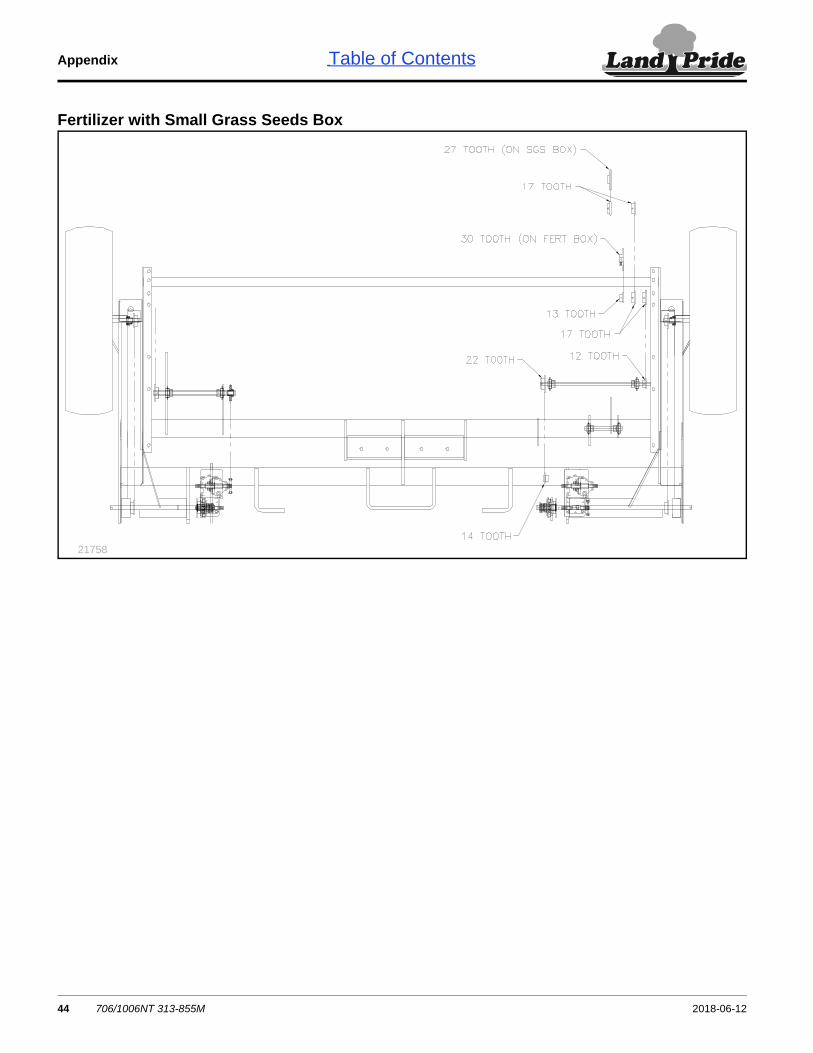
Fertilizer with Small Grass Seeds Box
21758
706/1006NT 313-855M 2018-06-1244

Index Table of Contents
Index
Aaccident, hydraulic ............................... 2amber reflector ..................................... 6
CCAUTION, defined ............................... 1chemicals ............................................. 2children ................................................ 2clean-out .............................................. 2clothing ................................................. 2containers ............................................ 2coulter
depth control ............................... 21disk scraper ................................ 24down pressure
spring length ........................ 22weights ................................ 22
individual adjustment .................. 22coulter springs
See coulter, down pressurecustomer service ................................ 12DDANGER, defined ................................ 1daytime reflector .................................. 6dealer locator .......................................ivdecal replacement ................................ 5decals
cautionchain ................................. 8,9general ................................... 7not a step ............................... 7operation ................................ 7
dangerchemical .............................. 10
warningfalling ................................... 10hand crush ........................... 10hydraulic ................................ 9jack angle .............................. 9speed ..................................... 9
decal, safety ......................................... 5description, drill .................................. 11directions ............................................ 11disposal ................................................ 2
Ffertilizer attachment ............................ 36fire ........................................................ 1fumes ................................................... 4
Ggauge wheel ......................................... 3
idler adjustment .......................... 24gearbox .............................................. 33
Hharrow ................................................ 35
adjustments ................................ 26
chain ............................................26headphones ..........................................2hearing..................................................2high pressure fluids ..............................2hitching ...............................................13Hydraulics
Rephasing cylinders ....................16hydraulics
parking.........................................20plastic hose holder ......................15rephasing cylinders .....................16schematics ..................................40
Iintended usage ...................................11Jjack
storage ........................................14Lleaks .....................................................2left-hand, defined ................................11leveling ...............................................17lift-assist tire..........................................3lights .....................................................3liquid treatments ...................................2lock-out hub ........................................20Loctite 525 ..........................................33lubrication ...........................................31
Mmaintenance safety ..............................4manuals ..............................................11marker ................................................36
Nnative grass attachment .....................37no-step..................................................3Note, defined ......................................11NOTICE, defined ................................11
OOpener
"W" clip ........................................23opener
adjustments .................................23down pressure .............................23operation .....................................19press wheels ...............................23seeding depth ..............................23springs .........................................23
orientation rose ...................................11owners manual ...................................11
Pparking and unhitching .......................20parts....................................................12parts manual ................................. iv,11plastic hose holder
See hydraulics, plastic hose holder
protective equipment ............................ 2
QQR Code ..............................................iv
Rred reflector ..................................... 5,6reflector
amber ............................................ 6daytime ......................................... 6red ............................................ 5,6SMV .............................................. 5
reflectors, safety ................................... 5repair parts ......................................... 12riders .................................................... 2right-hand, defined ............................. 11rose, orientation ................................. 11
Ssafety
chainhitching ................................ 14parking ................................. 20
safety decal .......................................... 5safety information
decals ........................................... 5safety symbol ....................................... 1Seed Lok ............................................ 36seed rate manual ............................... 11serial number ..................................... 12service ................................................ 12shutdown .............................................. 3slow moving vehicle ............................. 5Small seeds attachment ..................... 36smoke .................................................. 2SMV (Slow Moving Vehicle) ................. 5spring tine harrow
See harrowstorage .......................................... 3,30support ............................................... 12symbol, safety ...................................... 1Ttables
documents .................................. 11tires ...................................................... 3transport speed .................................... 3transporting ........................................ 19WWARNING, defined .............................. 1welding ................................................. 4
Numerics20 mph ................................................. 330 kph .................................................. 3313-521M, manual ............................. 11313-521P, manual .............................. 11313-526B, manual .............................. 11525, Loctite ........................................ 33
2018-06-12 706/1006NT 313-855M 45

Index Table of Contents
788067, gear lube .............................. 33818-055C, reflector .............................. 5818-518C, decal .................................. 8
818-578C, high pressure hazard ..........9818-611C, decal .................................10838-265C, reflector ...............................6
838-266C, reflector ..........................5,6
706/1006NT 313-855M 2018-06-1246

Table of Contents
2018-06-12 706/1006NT 313-855M 47
Model Number: __________________________ Serial___________________________
38112
Warranty
Land Pride warrants to the original purchaser that this Land Pride unit will befree from defects in material and workmanship for a period of one year from thefirst use date when used as intended and under normal service and conditions forpersonal use; ninety days for custom/commercial or rental use. This Warranty islimited to the replacement of any defective part by Land Pride and theinstallation by the dealer of any such replacement part. Land Pride reserves theright to inspect any equipment or part which are claimed to have been defectivein material or workmanship.
The following items and/or conditions are not covered under warranty: failuresresulting from abuse or misuse of the equipment, failures occurring as a result ofaccidental damage or acts of God, failures resulting from alterations ormodifications, failures caused by lack of normal maintenance as outlined in theoperator’s manual, repairs made by non-authorized personnel, items replaced orrepaired due to normal wear (such as wear items and ground engagingcomponents), repeat repair due to improper diagnosis or repair by the dealer,temporary repairs, service calls and/or mileage to and from customer location,overtime premium, or unit hauling expenses. The warranty may be voided if theunit is towed at speeds in excess of 20 miles per hour (32 kilometers per hour),or is used in soils with rocks, stumps, or other obstructions.
Land Pride reserves the right to make changes in materials or design of theproduct at any time without notice. The warranty shall not be interpreted torender Land Pride liable for damages of any kind, direct or consequential orcontingent to property. Furthermore, Land Pride shall not be liable for damagesresulting from any cause beyond its control. This warranty does not extend tocrop loss, losses caused by planting or harvest delays or any expense or loss oflabor, supplies, rental machinery, or for any other reason.
No other warranty of any kind whatsoever express or implied, is made withrespect to this sale; and all implied warranties of merchantability and fitness fora particular purpose which exceed the obligations set forth in this writtenwarranty are hereby disclaimed and excluded from this sale.
This warranty is not valid unless the unit is registered with Land Pride within 10days from the date of the original purchase.

Corporate Office: P.O. Box 5060Salina, Kansas 67402-5060 USA
www.landpride.com
Table of Contents