table of contents - etneo energia... · type of savonius rotor and three airfoil blades of...
TRANSCRIPT
1

2
Table of Contents
WARNING .................................................................................................... 6
DISCLAIMER ................................................................................................. 8
1. Safety Precautions ................................................................................. 9
1.1 Mechanical Hazards ...................................................................... 10
1.2 Electrical Hazards ......................................................................... 11
1.3 Assembly ...................................................................................... 12
1.4 Installation ................................................................................... 13
1.5 Operation ..................................................................................... 14
2. Introduction ........................................................................................ 15
2.1. DS-300 Specification .................................................................... 17
2.2. DS-300 Standard Packing ............................................................. 18
2.4. DS-300 Wind Power System Controllers ........................................ 20
2.5. DS-300 Optional Parts .................................................................. 21
3. Preparation of Assembly and Installation ............................................. 22
3.1 Selecting Location ......................................................................... 22
3.2 Mast Preparation ........................................................................... 24
3.3 Foundation Guide for DS-300 ....................................................... 29
3.3.1 Ground Foundation ................................................................. 30
3.3.2 Roof Foundation ..................................................................... 34
4. DS-300 Assembly and Installation ....................................................... 38
3
4.1 Tools Required for Assembly and Installation ................................ 38
4.2 DS-300 VAWT Assembly ............................................................... 40
4.3 DS-300 Installation ....................................................................... 44
5. Wiring ................................................................................................. 50
5.1 General Information ...................................................................... 50
5.2 DS-300 Wire Size .......................................................................... 50
5.3 DS-300 Wiring Diagram ................................................................ 52
5.4 PV Charging .................................................................................. 55
5.5 Grounding .................................................................................... 56
5.6 Fusing .......................................................................................... 56
6. Warranty ............................................................................................. 58

4
Table of Figures
Figure 2-1 General View of the DS-300 VAWT System ................................ 16
Figure 2-2 DS-300 Standard Packing Contents .......................................... 20
Figure 2-3 System Controllers ................................................................... 21
Figure 3-1 Dimension for Mast .................................................................. 26
Figure 3-2 Optional Mast Design ............................................................... 29
Figure 3-3 Ground Foundation Construction Reference .............................. 31
Figure 3-4 AnchoringTemplates ................................................................ 33
Figure 3-5 Foundation for Roof Installation Reference ............................... 35
Figure 4-1 Required Tools for Assembly and Installation............................ 39
Figure 4-2 DS-300 Assembly Procedures - 1 ............................................. 40
Figure 4-3 DS-300 Assembly Procedures – 2 ............................................. 42
Figure 4-4 DS-300 Assembly Procedures – 3 ............................................. 43
Figure 4-5 DS-300 Installation Procedures – 1 ........................................... 45
Figure 4-6 DS-300 Installation Procedures – 2 ........................................... 46
Figure 4-7 DS-300 Installation Procedures – 3 ........................................... 47
Figure 4-8 DS-300 Installation Procedures – 4 ........................................... 48
Figure 5-1 Wiring Diagram for Wind Charge Controller (WS320) ................. 53

5
Table Index
Table 2-1 DS-300 Technical Specification ................................................. 17
Table 2-2 DS-300 Components ................................................................. 18
Table 5-1 Wire Sizing Reference ................................................................ 52
Table 5-2 DS-300 Wiring Size Reference ................................................... 55
6
WARNING
THIS USER’ MANUAL PROVIDES INSTRUCTIONS AND GUIDELINES FOR
ASSISTANCE WITH ASSEMBLY AND INSTALLATION OF THE HI-VAWT’S DS-
300 VERTICAL AXIS WIND TURBINE. ALTHOUGH THE DS-300 VAWT HAS
BEEN DESIGNED AS EASY AS POSSIBLE FOR THE INSTALLATION, IT STILL
REQUIRES SPECIALIZED SKILLS, TOOLS AND EXPERIENCE AS WELL. FOR THE
PURPOSES OF ASSEMBLING, INSTALLING, OPERATING AND MAINTAINING
THE DS-300 VAWT, WE ASSUME THAT PERSONNEL WHO INVOLVED IN THE
WHOLE PROCESSES HAS THE SKILLS, TOOLS REQUIRED TO DO SO. NO ONE
SHOULD ATTEMPT TO ASSEMBLE, INSTALL, OPERATE AND MAINTAIN THE
DS-300 VAWT SYSTEM WITHOUT THE NECESSARY SKILLS, EXPERIENCE,
TOOLS AND SAFETY EQUIPMENT.
DISASSEMBLING THE PARTS FROM ORIGIONAL IS RESTRICTED. ALL PRE-
ASSEMBLED PARTS ARE FACTORY ADJUSTED, BALANCED AND TESTED. HI
VAWT TECHNOLOGY CORPORATION ASSUMES NO WARRANTIES AND
LIABILITIES OF DOING SO.
HI-VAWT TECHNOLOGY CORPORATION (Hi-VAWT) ASSUMES NO DIRECT
OR CONSEQUENTIAL LIABILITY IF FAULTY OR DANGEROUS ASSEMBLING,
INSTALLATION OR MAINTENANCE PRACTICES ARE PERFORMED. PLEASE
CONTACT HI-VAWT TECHNOLOGY CORPOATION IF CONSULTATION OR
ASSISTANCE IS REQUIRED.
7
HI-VAWT RECOMMENDS THE DS-300 VAWT SYSTEM SHOULD BE SITED
ACCORDINGLY IN AN EXCLUSION ZONE WITH CONTROLLING PUBLIC
ACCESS. APPROPRIATE WARNING SIGNS SHOULD BE PLACED ON THE
OPERATING SITE.
THE DS-300 SHOULD NOT BE INSTALLED NEAR UNPROTECTED POWER
LINES, TREES OR ANY OBJECTS THAT WOULD POSSIBLY CAUSE THE
HAZARDS OF THE OPERATION.
Etneo Italia srl
Via Giovanni Bovio n°6 28100 Novara Italia
Tel: +39 0321.697200
Fax: +39 0321.688515
E-Mail: [email protected]
Website: http://www.etneo.com/en/
8
DISCLAIMER
Although Hi-VAWT recommends reading the entire manual thoroughly
prior to assembly and installation to ensure proper performance and
safety, this manual is intended as a guide only. It should not be
considered as a replacement of professional services or as a definitive
text for assembling and installing the DS-300 VAWT systems.
Hi-VAWT makes no warranties by either expressed or implied that the
information contained in the manual is accurate or complete. Hi-VAWT
Technology Corporation makes no warranties of fitness for a particular
purpose and /or site. Hi-VAWT will not be responsible for any direct or
consequential damages, or an incidental expense.
All instructions, figures and diagrams are believed to be accurate at the
time of printing. The success and safety in working with tools depend
greatly on individual accuracy, skill and caution. For this reason, Hi-VAWT
is not able to guarantee the result of any contained procedure in the
manual, nor can they assume responsibility for any damage to property or
injury to persons resulting from procedures contained in this manual.
Persons who engage in the procedures take their own responsibility and
risk.
Actual power resources and selected site conditions will highly affect the
energy production, which will vary with wind turbine maintenance,
9
surrounding environment, therefore, Hi-VAWT makes no representation
or warranties regarding energy production.
Wind generators, like other sources of electrical power, Must be installed
following the guidelines established by local and national regulations.
Please consult a local electrical contractor for details and regulations.
The information and all specifications contained within this manual are
subject to change without notice.
1. Safety Precautions
The DS-300 is designed with user safety in mind. However, there are
inherent dangers involved with any structural, mechanical and electrical
equipment, the surrounding environment as well.
Safety must be the primary concern as you plan the location, assembly,
installation and operation of the DS-300 VAWT. At all times be aware of
electrical, mechanical and rotor blade hazards.
This Owner’s Manual contains important instructions, guidelines and
safety notes that should be followed during the installation and
maintenance of the Hi-VAWT’s DS-300 VAWT.
Please read thoroughly and follow the instructions in this USER’S MANUAL
before assembling and installing the DS-300 VAWT.
10
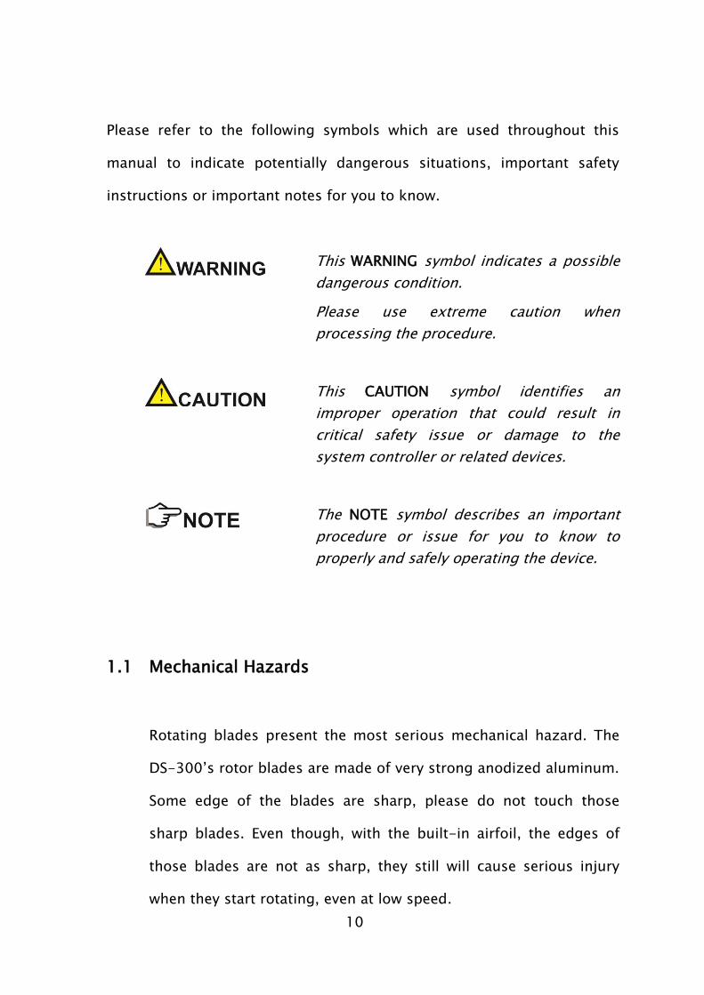
Please refer to the following symbols which are used throughout this
manual to indicate potentially dangerous situations, important safety
instructions or important notes for you to know.
This WARNING symbol indicates a possible
dangerous condition.
Please use extreme caution when
processing the procedure.
This CAUTION symbol identifies an
improper operation that could result in
critical safety issue or damage to the
system controller or related devices.
The NOTE symbol describes an important
procedure or issue for you to know to
properly and safely operating the device.
1.1 Mechanical Hazards
Rotating blades present the most serious mechanical hazard. The
DS-300’s rotor blades are made of very strong anodized aluminum.
Some edge of the blades are sharp, please do not touch those
sharp blades. Even though, with the built-in airfoil, the edges of
those blades are not as sharp, they still will cause serious injury
when they start rotating, even at low speed.
11
NEVER TOUCH THE RUNNING ROTOR.
NEVER TRY TO STOP THE RUNNING ROTOR BY HAND.
DO NOT INSTALL THE DS-300 VAWT SYSTEM WHERE ANYONE
CAN APPROACH THE PATH OF THE BLADES.
AVOID ANY OBJECTS TOUCHING THE RUNNING ROTOR.
1.2 Electrical Hazards
The DS-300 VAWT System is equipped with sophisticated generator
and designed to provide protection from electrical dangers.
Heat in wiring systems is often a result of too much current flowing
through and undersized wire or through a bad connection. It is
important to follow the suggested wire-sizing chart to ensure a
safe electrical system
The battery, if applied, should never be short-circuited as it will
result a danger of setting the battery and cable on fire. In order to
12
avoid the threat and protect the cabling, fuses should be installed
in the lines connecting to the battery.
WIRING CABLE WITH INSUFFICIENTLY DIMENTION CROSS
SECTION CAN CAUSE ELECTRICAL FIRE.
NEVER SHORT-CIRCUIT THE BATTERY IF APPLIED.
1.3 Assembly
The DS-300 VAWT System is designed in “All Most Ready to Use”
format and shipped with factory pre-assembled packing. The only
assembly work required is Darrieus blades assembly. This user’s
manual will guide you through the assembly procedures with
detailed illustrations.
Please carefully read the assembly instructions in this manual
before proceeding.
It is important to have a suitable working environment for
performing the assembly tasks.
Refer to the suggested list of tools required for the assembly
and have all of them ready before proceeding.
13
PLEASE ALWAYS KEEP SAFETY IN MIND WHILE PERFORMING THE
ASSEMBLY PROCEDURES.
AWAYS WEAR SAFE HELMET AND GLOVES!
1.4 Installation
A fall from the height at which a wind turbine is ordinarily mounted
will often result in death or serious injury. Therefore whenever
practicably carry out as much work as possible on the wind turbine
at ground level. If it is necessary to work on the installation at such
height then use an appropriate access system such as a mast that is
designed to carry the load of a person; a man-rated winch or rope
access system; a hydraulic lift or other safe working platform. Wear
appropriate safety equipment and make the general working area
as tidy and safe as possible. Work during the daylight on windless
days. Above all else think carefully about what you need to do and
plan your work carefully, have all the tools and equipment ready
before your start.
Installation procedures should be performed as much as
possible at ground level.
Use safety harnesses, safe helmets, gloves, etc.
14
Make sure that all batteries, if applied, are disconnected from
the system throughout the installation process.
The DS-300 generator should be short-circuited to prevent
unintended wind turbine rotating during the shipment. Please
install the extension cable on the ground level and keep it
short-circuited throughout the installation process.
Please keep the rotor straight up or lie on the support stands at
all-time during the installation process to prevent the blades
twisted or lost balance.
Please perform the installation at a calm and windless day.
1.5 Operation
Please check the support structures, blades and electrical system
on regular basis.
Even though the rotor blades are very strong, however, if they
come in contact with a solid object, they can be damaged or
even broken.
15
When perform routine inspections, or at anytime you must
approach the path of the blades, please disconnect the power
leads from the batteries and short-circuit the wind turbine
output leads (use the Stop Switch after installation or tie the
output leads together) to stop the rotor blades from rotating.
The DS-300 is designed to be shut down through the use of
stop switch (brake switch).
NEVER APPROACH THE TURBINE DURING OPERATION.
2. Introduction
The DS-300 is a hybrid Vertical Axis Wind Turbine (VAWT) system which
combines drag-based design and lift-based design. It incorporates an S-
type of Savonius rotor and three airfoil blades of egg-beater shape
Darrieus to maximize the output performance.
The following Figure 2-1 shows a general view and major components of
the DS-300 VAWT System.
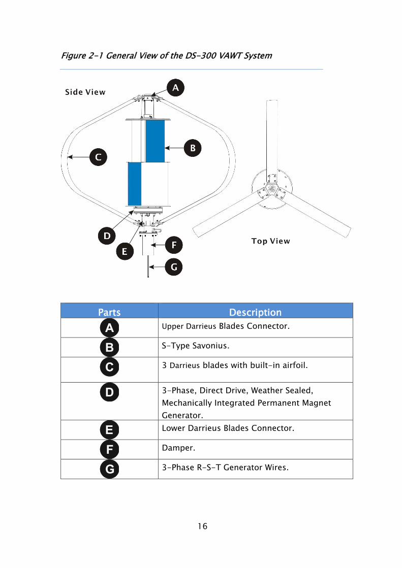
16
Figure 2-1 General View of the DS-300 VAWT System
Parts Description
Upper Darrieus Blades Connector.
S-Type Savonius.
3 Darrieus blades with built-in airfoil.
3-Phase, Direct Drive, Weather Sealed,
Mechanically Integrated Permanent Magnet
Generator.
Lower Darrieus Blades Connector.
Damper.
3-Phase R-S-T Generator Wires.
17
2.1. DS-300 Specification
The following table shows the technical specification of the DS-300
Wind Turbine.
Table 2-1 DS-300 Technical Specification
General Dimension
Rotor Diameter: 1,245 mm
Height:
Weight:
1,060 mm
25.5 Kgs
Blades
Number of Blade: 3
Blade Material: Anodized Aluminum
Operation Mode
Cut-In Wind Speed: <3 m/s
Cut-Out Wind Speed: 15 m/s
Survival Wind Speed: 60 m/s (3-seconds gust)
Safety Mechanism
Over Speed Braking: Yes. (Setup by Power Controller)
Manual Brake: 3-phase short-circuit Switch
Generator
Type: AC, Direct Drive, Weather Sealed, 3-
Phase Synchronism PMG.
Rated Output: 300 W @ 13.5 m/s
Mounting
Foundation Mounting: Min. Height above ground: 3 meters.
18
Roof Mounting: Min. Height above roof: 2 meters.
Bedplate Mounting: Used where deep excavation cannot be
applied
Warranty
Limited Warranty: 1 year on components.
2.2. DS-300 Standard Packing
Please check all components you receive from the shipment with
the packing list that comes with the purchase invoice or the
enclosed parts list in the shipment. Ensure that you receive all
standard components or parts for the DS-300 accordingly. If any
missing parts from the original packing, please contact Hi-VAWT
Technology Corporation for replacement.
Table 2-2 shows the standard packing of DS-300 VAWT System.
Please also refer to Figure 2-2 for part locations. Detail assembly
instructions will be discussed in the Chapter 4 - Assembly and
Installation.
Table 2-2 DS-300 Components
Labels Description Quantity Included
Anodized Aluminum Blade
(Assembly Needed)
3
Pre-assembled Components 1 Set
1 Upper Blades Connecting 1
19
Plate
2 S-Type Savonius
1
3 Vertical Axis
1
4 300W PM Generator
1
5 Lower Blades Connecting
Plate
1
6 R.S.T. Generator Wiring
Cables
3
7 Mast Connector with Damper
1
8 Wind Turbine Surge Wire
(Connected between Damper
and Flange of the Mast)
1
Bolt Sets
1 M10 x 25mm Button Hex
Head Bolts and Nuts (Set)
18
2 M8 x 25mm Button Hex
Head Bolts and Nuts
6
3 M8 x 30mm Hex Head
Bolts/Washers
6
7-1 Set Screw M10 x 10mm 1
7-2 Socket Countersunk Head Cap
Screw M5 x 16mm
2
8-1 M10 x 20mm Hexagon Socket
Head Bolt and Nut (Set)
1
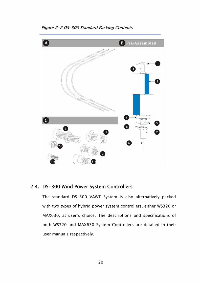
20
Figure 2-2 DS-300 Standard Packing Contents
2.4. DS-300 Wind Power System Controllers
The standard DS-300 VAWT System is also alternatively packed
with two types of hybrid power system controllers, either WS320 or
MAX630, at user’s choice. The descriptions and specifications of
both WS320 and MAX630 System Controllers are detailed in their
user manuals respectively.
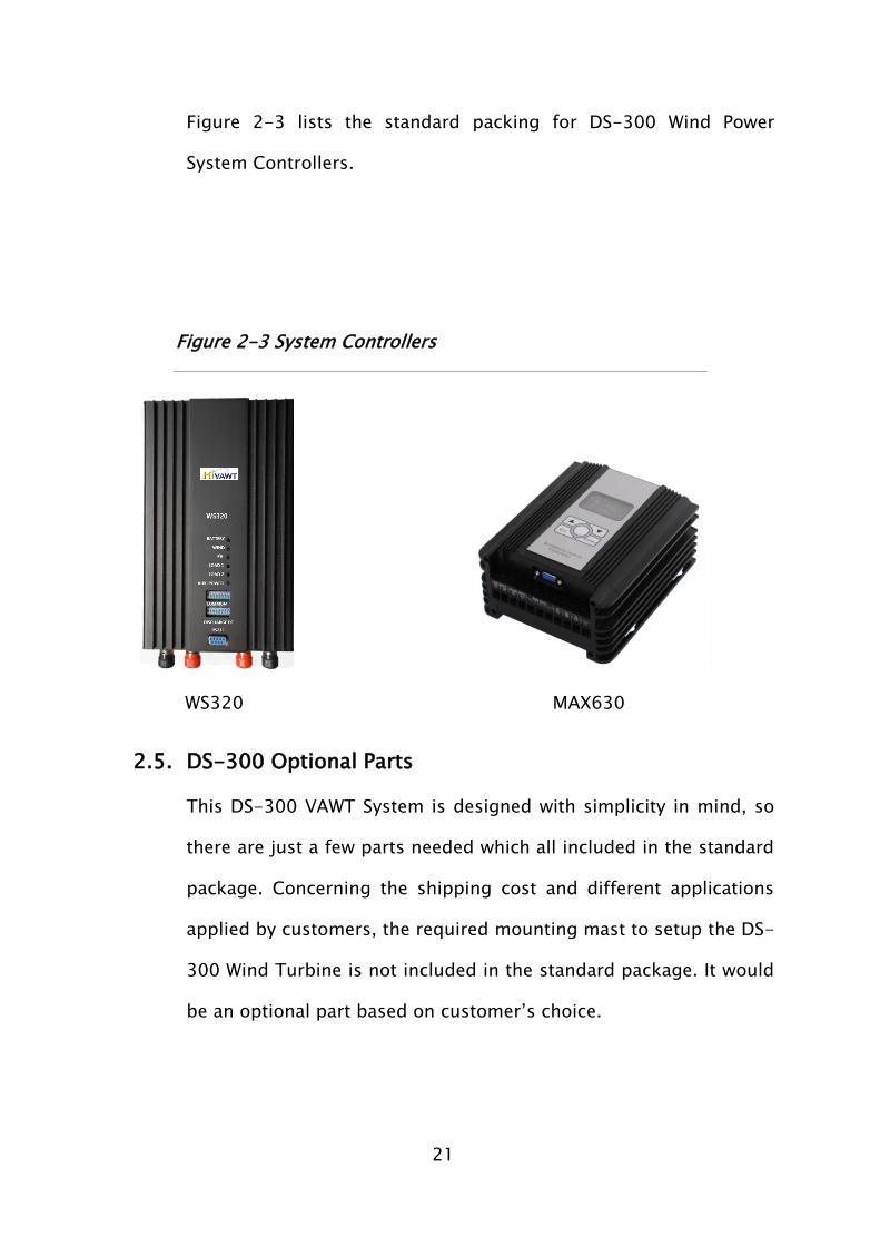
21
Figure 2-3 lists the standard packing for DS-300 Wind Power
System Controllers.
Figure 2-3 System Controllers
WS320 MAX630
2.5. DS-300 Optional Parts
This DS-300 VAWT System is designed with simplicity in mind, so
there are just a few parts needed which all included in the standard
package. Concerning the shipping cost and different applications
applied by customers, the required mounting mast to setup the DS-
300 Wind Turbine is not included in the standard package. It would
be an optional part based on customer’s choice.
22
The detail description of the mounting mast will be explored in
Chapter 3.
3. Preparation of Assembly and Installation
Before going through the DS-300 VAWT System installation
procedures, please double check parts included in the package.
Prepare all required tools and equipments accordingly and have them
ready on hands. More importantly, all safety issues have been well
thought and followed.
3.1 Selecting Location
The DS-300 Wind Turbine is designed with flexibility to fulfill user’s
applications. It can be installed along the street, sea shore, on the
mountain, in the city, urban area, or just right on top of the roof of
the building. The major key factor of affecting the performance of
DS-300 Wind Turbine for all proposed applications is the location
of optimizing wind energy.
We assume that the proposed site of installing the DS-300
VAWT System has been well evaluated by users themselves for
optimizing the wind energy environment before any installing
procedures performed.

23
DO NOT install the DS-300 VAWT System at a site where
anyone can easily approach the rotating blades.
DO NOT install the DS-300 VAWT System at a site
surrounded by obstructions. For example, Trees, power lines,
etc.
DO NOT install the DS-300 VAWT System at a site with
improper structure to hold the DS-300 System.
Always follow your local regulations, codes about restrictions
applied to such system installation.
Always have your DS-300 grounded to avoid the lightning
strike.
Perform the installation of the DS-300 VAWT System in a
calm and windless day.
Perform all required assembly for the DS-300 VAWT System
at ground level.
24
3.2 Mast Preparation
As mentioned before, shipping charge of the mast made by Hi-
VAWT will be costly. If you prefer making your own mast for DS-
300 VAWT System rather than purchasing from Hi-VAWT, we will
show you here how the mast can be made by your local supplier.
In the Figure 3-1, the Mast Specification was originally designed
and tested on the DS-300 VAWT System. It has been approved and
applied as the standard DS-300 VAWT System. It is important to
follow the diameters shown in Figure 3-1 for Mounting Flange and
Mast of the DS-300 VAWT System.
Please carefully check the structure of the building if you are
going to install DS-300 VAWT System on the roof. Make sure the
structure is strong enough to endure DS-300 VAWT System in
terms of total weight, impact from gusty wind or earthquake, etc.
Hi-VAWT Technology Corporation suggests the length of the
mast is 2 meters for the roof installation and 4 meters for the
ground.

25
Carefully check the surrounding area when determines the
length of the mast. Avoid any existing objects that affect the
performance of wind energy or cause hazards.
The following Figure 3-1 shows the diagram for making the mast.
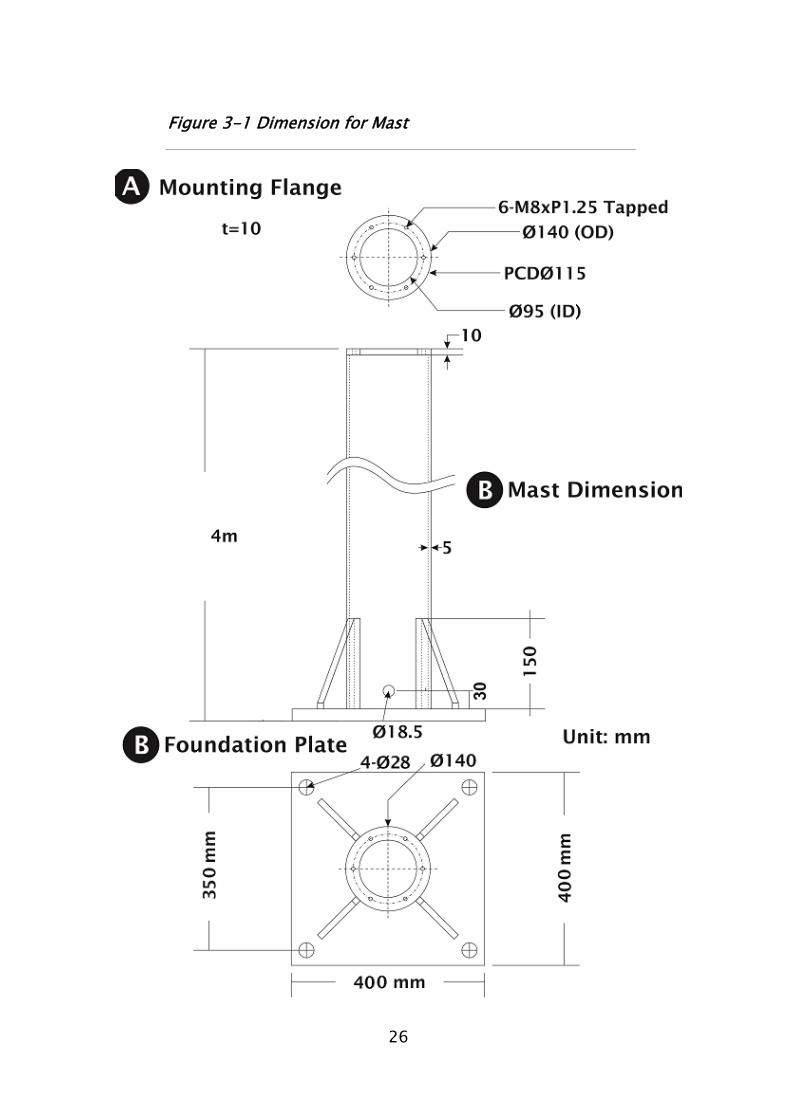
26
Figure 3-1 Dimension for Mast
27
This portion shows the dimension of the
mounting flange which should be welded on
top of the mast for connection with the DS-
300 VAWT System.
Flange Inner Dia. = 95mm
Flange Outer Dia. = 140mm
6 - 8mmxP1.25 Tapped bolt holes
on PCD 115 mm (60° each) Flange thickness = 10mm
Mast Dimension:
Prototype Design material: 140mm x
5mm galvanized steel pipe.
Mast Outer Dia. = 140mm
Mast Inner Dial. = 130mm
Standard Length of the Mast = 4m
Mounting flange welded on the top of
the Mast.
Foundation Plate welded under the
bottom of the Mast with 4 support ribs
(t=10).
Drill a18.5mm diameter hole at 30mm
above the bottom of the mast. This
hole is reserved for wiring cable exit. If
an underground conduit is applied in
the concrete foundation, then ignore
this exit.
Foundation Plate Dimension:
400mm x 400mm
Thickness = 14mm
4 x 28mm bolt holes on 350mm x
350mm.
4 x 15mm in thickness of support ribs

28
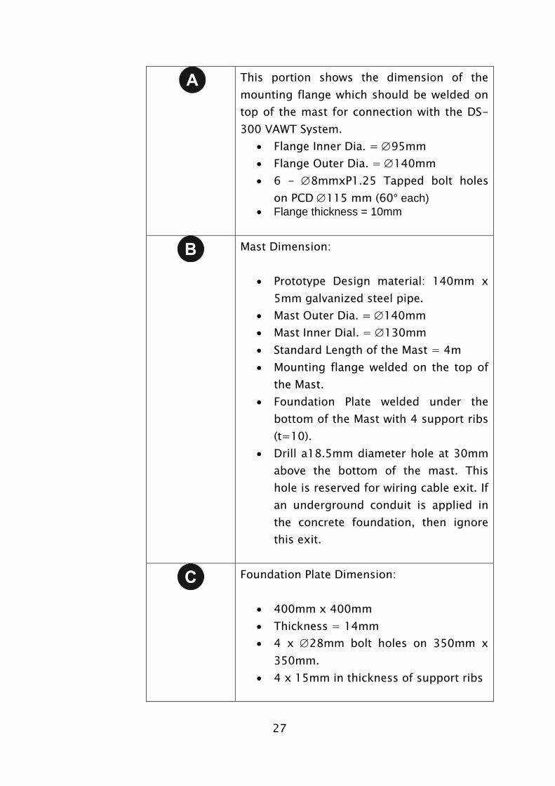
Figure 3-2 shows an optional design of the mounting mast. You
may use hinge type mechanism at one side of the foundation plate
to make an easy way to access the DS-300 by lowering down or
lifting up the mast.
29
Figure 3-2 Optional Mast Design
3.3 Foundation Guide for DS-300
Before constructing the foundation for the DS-300 VAWT System,
read these instructions carefully. These instructions are only
30
intended to be a guide for concrete foundations on solid soils or
suitable roof infrastructure. Please contact your local civil or
structure engineer for more information.
3.3.1 Ground Foundation
This section of how to prepare foundation for DS-300 VAWT
System ground installation is only intended to be a guideline for
building concrete foundation on solid soils infrastructure. Please
contact your local civil or structure engineer for more
information.
Based on Hi-VAWT’s standard 4m mast design to accommodate
52.5 m/s extreme wind condition (Wind Class III) on top Sand,
silty sand, clayey sand, silty gravel and clayey gravel (IBC Soil
Class 4), initially the foundation should be prepared as 0.778
cubic meters in dimension (L 700mm x W 700 mm x Depth
1000mm) dug into the soil. Please follow the diagram shown in
the Figure 3-3.
31
Figure 3-3 Ground Foundation Construction Reference
.
Dimension Chart
Lpx 700 mm
Concrete
L 1000 mm
D 600 mm
T 400 mm
32
List of Material Required
1 0.778 Cubic meter of concrete – 3000 psi or better.
2 4-M24 with length of 900mm galvanized Anchor Bolts.
One end is bent into a hook shape.
3 4-M24 Nuts.
4 4 galvanized washers.
5 Electrical conduit, 100mm diameter pipe or similar, maybe
needed for underground wiring, if applied.
Follow the Figure 3-4 diagram and make anchoring
templates with steel plate. These templates will be used to
hold four anchors bolts vertically and electrical conduit (if
applied) on the precise position while pouring concrete into
the foundation hole later.
400mm height from the bottom should be expanded to L
1,000mm x W 1,000mm.
Insert 4 threaded M24 Anchor Bolts with holding templates
and secure them on the position. Make sure there have at
least 100mm of thread above the concrete level.

33
Figure 3-4 AnchoringTemplates
Fix the conduit through the center of the template and push
the other end of the conduit to the side of the foundation (if
applied).
Pouring concrete by using a vibrating poker to remove air
voids from the pour. It is very important to make sure the all
eight rods are hooked under the rebar. Once the concrete is
34
all poured, make sure that the template has no air voids
directly underneath. More importantly, make sure the
template is leveled out.
Next, clear excess concrete from above the template and use
a suitable cover to prevent the foundation from rain. Wait
until the concrete has set completely before removing the
template(It will take one to four weeks).
Just remember, a solid with perfect leveled foundation is one of the
key factors to achieve the success of the installation.
3.3.2 Roof Foundation
Installation of the DS-300 VAWT System on the roof may be
much easier than it is on the ground. But special thought of
the building structure has to be carefully taken into account
before the installation.
We strongly suggest that the location on top roof surface
should be above the concrete beam. Any surface other than
concrete, the users should contact their own architect or
structure engineer for advice and take their own
responsibility for any possible dangers.
35
The concrete roof should be thick enough to allow 100mm
drilling down from the surface. Please follow the template
explained in Section 3.3.1 and use this template as a guide
and drill four ø20 holes 100mm deep down to the surface.
Insert and secure four threaded rod to each hole, use 4mm
plywood to make a square holding template with inner
dimension T1 x T2 x T3, pour the concrete into this square
template, then put the first template on top of the square
template to hold four rods temporarily before the concrete
set completely and keep the surface leveled.
Figure 3-5 Foundation for Roof Installation Reference
36
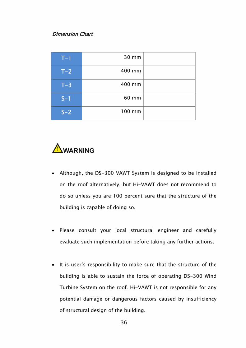
Dimension Chart
T-1 30 mm
T-2 400 mm
T-3 400 mm
S-1 60 mm
S-2 100 mm
Although, the DS-300 VAWT System is designed to be installed
on the roof alternatively, but Hi-VAWT does not recommend to
do so unless you are 100 percent sure that the structure of the
building is capable of doing so.
Please consult your local structural engineer and carefully
evaluate such implementation before taking any further actions.
It is user’s responsibility to make sure that the structure of the
building is able to sustain the force of operating DS-300 Wind
Turbine System on the roof. Hi-VAWT is not responsible for any
potential damage or dangerous factors caused by insufficiency
of structural design of the building.

37
Please closely follow your local government’s regulations
regarding related issues if you are going to install DS-300 on
the roof.
If you are going to install the DS-300 on the ground level,
please consult your local civil engineer and carefully evaluate the
nature of the soil and design of the foundation accordingly.
38
4. DS-300 Assembly and Installation
Before starting the assembly and installation of the DS-300 Wind
Turbine System, please well prepare all required tools to complete the
assembly and installation.
4.1 Tools Required for Assembly and Installation
As the DS-300 is factory pre-assembled, only a few tools required
for finishing entire assembly and installation. We are strongly
recommend having a crane with suitable capacity to haul up the
mounting mast to desired location and also lift up the DS-300 to
the mounting flange. Please refer to Figure 4-1 for your tool
preparation.

39
Figure 4-1 Required Tools for Assembly and Installation
We strongly recommend you to prepare all suggested tools
before proceeding the assembly and installation.
Please always keep safety in mind while working on the
assembly and installation.
Preparing any extra equipments or safety devices accordingly
if instructed by your local authority.
40
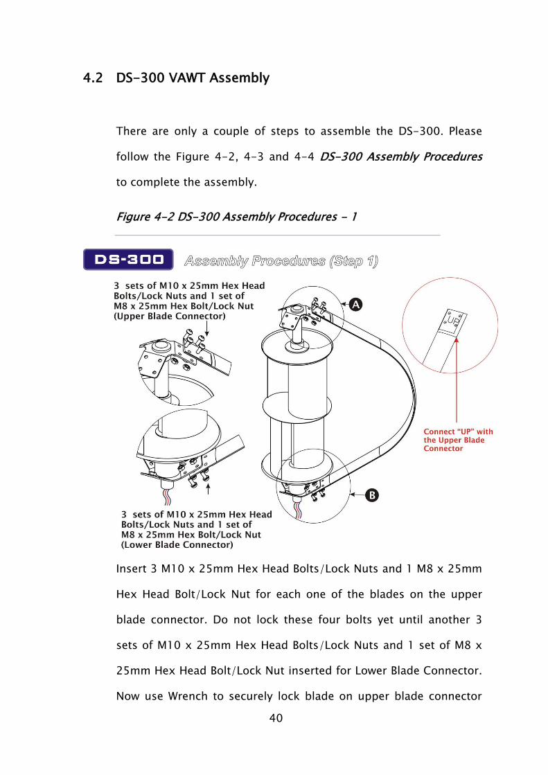
4.2 DS-300 VAWT Assembly
There are only a couple of steps to assemble the DS-300. Please
follow the Figure 4-2, 4-3 and 4-4 DS-300 Assembly Procedures
to complete the assembly.
Figure 4-2 DS-300 Assembly Procedures - 1
Insert 3 M10 x 25mm Hex Head Bolts/Lock Nuts and 1 M8 x 25mm
Hex Head Bolt/Lock Nut for each one of the blades on the upper
blade connector. Do not lock these four bolts yet until another 3
sets of M10 x 25mm Hex Head Bolts/Lock Nuts and 1 set of M8 x
25mm Hex Head Bolt/Lock Nut inserted for Lower Blade Connector.
Now use Wrench to securely lock blade on upper blade connector
41
and lower blade connector. Repeat this step for second blade and
third blade and lower section as well.
The alignment of both upper blade connector and lower blade
connector has been factory pre-lined up.
Each blade has a mark of “UP” on one side, please connect
the “UP” end with the upper blade connector. Do not connect
“UP” end with lower blade connector.
If you are not able to see the “UP” mark on the blade, you
may find three M10 holes and on M8 hole on both blade and
connecting plate, just matching up each hole so you won’t
assemble the blade with wrong direction.
For safety concern, please short circuit the RST Generator
Wiring Cables temporarily to stop the rotor from rotation.
42
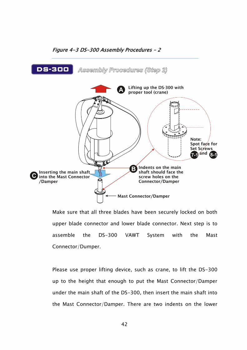
Figure 4-3 DS-300 Assembly Procedures – 2
Make sure that all three blades have been securely locked on both
upper blade connector and lower blade connector. Next step is to
assemble the DS-300 VAWT System with the Mast
Connector/Dumper.
Please use proper lifting device, such as crane, to lift the DS-300
up to the height that enough to put the Mast Connector/Damper
under the main shaft of the DS-300, then insert the main shaft into
the Mast Connector/Damper. There are two indents on the lower
43
main shaft and should be lined up with two lock screw holes on the
Mast Connector/Damper.
Indents on the lower main shaft must be lined up with lock
screw holes on the Mast Connector/Damper and securely
locked. Fail to do so will cause the generator cables broken
during break applied.
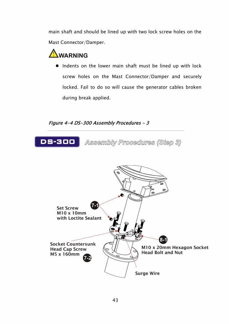
Figure 4-4 DS-300 Assembly Procedures – 3
44
Use the M10 x 10mm Hexagon Socket Screw to lock the upper hole
and M10 x 20mm Hexagon Socket Head Bolt and Nut to secure
lower section with the surge wire.
4.3 DS-300 Installation
Double check with assembly procedures and make sure all
screws are securely locked. Any loosen screw will cause
serious vibration and parts damaged.
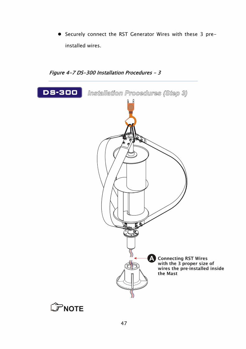
If you are going to install the DS-300 VAWT System at certain
height, please have proper safety devices ready for
proceeding installation.
45
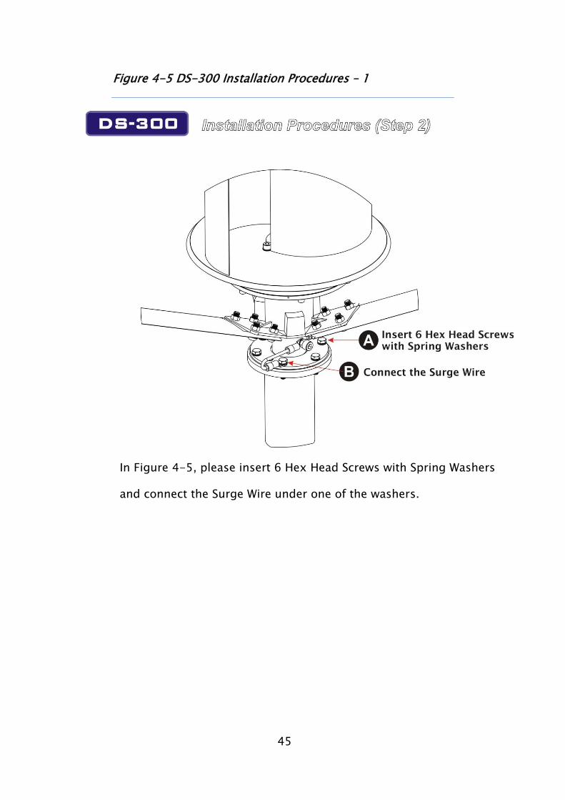
Figure 4-5 DS-300 Installation Procedures – 1
In Figure 4-5, please insert 6 Hex Head Screws with Spring Washers
and connect the Surge Wire under one of the washers.

46
Figure 4-6 DS-300 Installation Procedures – 2
Use proper lifting device (Crane) to lift up the DS-300 above the
mast flange.
There are 3 proper size of wires should be pre-installed inside
the Mast
47
Securely connect the RST Generator Wires with these 3 pre-
installed wires.
Figure 4-7 DS-300 Installation Procedures – 3
48
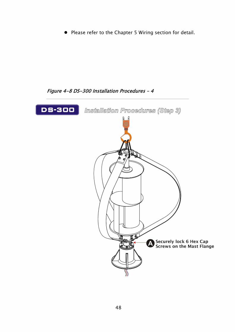
Please refer to the Chapter 5 Wiring section for detail.
Figure 4-8 DS-300 Installation Procedures – 4

49
Vertically insert the DS-300 into the Mast, and then securely lock
Mast Connector/Damper with the Mast Flange by 6 Hexagon Socket
Screws.
After the completion of this step, you have finish the DS-300 Wind
Turbine System and ready for further wiring procedures.
50
5. Wiring
5.1 General Information
Please refer to all local and national codes or special regulations to be
followed before installation. All works on the electrical system like
installation, maintenance, and repair should be carried out by qualified
technicians and make sure that they read all technical information and
instructions contained in related manuals.
The wiring diagram should be planned ahead and make sure all
required wiring components are well prepared accordingly.
Carefully plan all required electrical components, and install
electrical components first before any electrical connection.
Make sure that batteries (if applied) should be disconnected all
installation works are completed.
All electrical power cables should be physically protected. Run
the wires inside the mast of conduit for maximum protection.
5.2 DS-300 Wire Size
51
The cross section of the wire to be used depends on its length,
resistance and rated current. All electrical systems lose energy from
the resistance of the wire used. Larger wire size has smaller losses,
but can be considerably more costly.
Closely look at the site that the DS-300 VAWT System is to be
installed and measure the following distances:
Distance between DS-300 VAWT and the location of DS-300
Controller.
Distance between the solar panel and the DS-300 Controller.
Distance between the photodiode and the DS-300 Controller.
Distance between the DS-300 Controller and the Battery. It is
recommended that the length between DS-300 Controller
and Battery is no longer than 5 meters.
Please follow the reference table below for wire sizing:
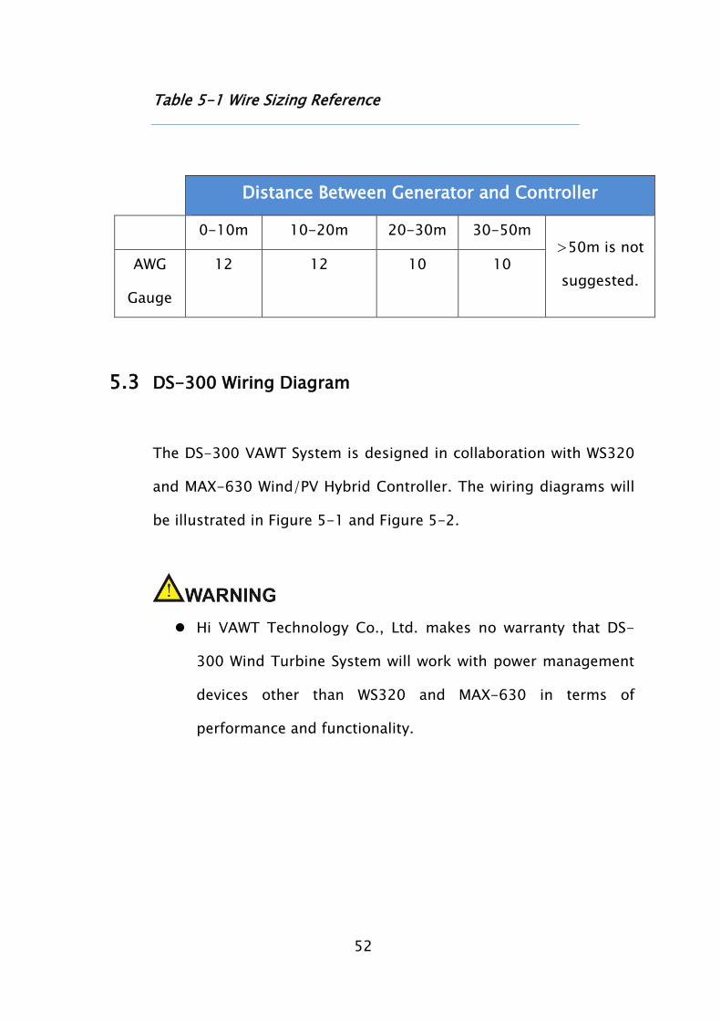
52
Table 5-1 Wire Sizing Reference
Distance Between Generator and Controller
0-10m 10-20m 20-30m 30-50m >50m is not
suggested. AWG
Gauge
12 12 10 10
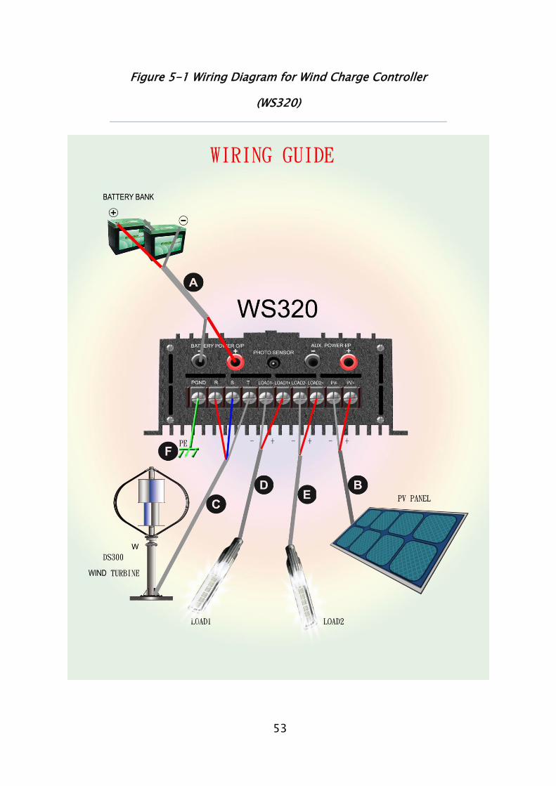
5.3 DS-300 Wiring Diagram
The DS-300 VAWT System is designed in collaboration with WS320
and MAX-630 Wind/PV Hybrid Controller. The wiring diagrams will
be illustrated in Figure 5-1 and Figure 5-2.
Hi VAWT Technology Co., Ltd. makes no warranty that DS-
300 Wind Turbine System will work with power management
devices other than WS320 and MAX-630 in terms of
performance and functionality.
53
Figure 5-1 Wiring Diagram for Wind Charge Controller
(WS320)
54
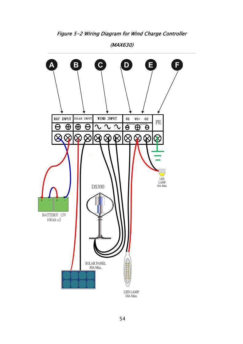
Figure 5-2 Wiring Diagram for Wind Charge Controller
(MAX630)
DS300
LED LAMP10A Max.
LED LAMP
10A Max.
┿━
SOLAR PANEL30A Max.
BATTERY 12V 100Ah x2
-
PE
55
Table 5-2 DS-300 Wiring Size Reference
Description Wire Size
Battery wires
Between battery and charger
AWG#10
Within 5m
PV wires AWG#12
R/S/T wires AWG#12
Within 50m
Loading #1 wires AWG#12
Loading #2 wires AWG#12
PE grounding wire AWG10
Please refer to the WS320/MAX630 hybrid Charge Controller
User’s Manual for further information.
5.4 PV Charging
To charge 24V battery bank, the PV charger is available for PV panel
which the voltage reaching between 30V and 50V. Please note that the
charger will not be available if the voltage of solar panel is lower than 24V
when charging for 24V battery bank.
56
5.5 Grounding
In order to protect the DS-300 Wind Turbine System against
damage by lightning, static or over voltage, properly grounding the
DS-300 Wind Turbine System is very important. Grounding
procedures must be followed along with any local electrical codes.
The design of the grounding system depends on the local
conditions, like the site of the installation, type of soil, or a
grounding bus already existing. If you are in doubt, contact your
local electrician for more information.
SEVERE TURBINE DAMAGE CAN RESULT FROM IMPROPER
GROUNDING!
FAILURE TO PROPERLY GROUND WILL VOID THE WARRANTY.
5.6 Fusing
To protect the battery against short circuit, fuse must be installed
in the positive line between the Controller and Battery. The
recommended fuse type is 20amp DC Slow-Blow fuse for 24V
system or appropriate automatic circuit breaker.
57
The fuse must be placed as close to the battery as possible,
however, not in the same compartment. Unsealed lead-acid
batteries have vent holes releasing hydrogen which forms
detonating gas with the ambient air. A spark when blowing the
fuse (or releasing an automatic circuit breaker) can detonate the
explosive mixture.
5.7 Stop Switch
[WS320]
A Stop Switch must be used with the DS-300 Wind Turbine System.
This Stop Switch is a DIP switch which is located at the front panel
of WS320. The Brake provide a convenient method for remotely and
manually shutting down the DS-300 turbine. This Stop Switch
disconnects the Controller then short-circuits the turbine causing
the turbine to stop spinning.
[MAX630]
In standby mode (controller digital part displays "RUN” and flashing),
long press the [ESC] button for 3 seconds, the Wind turbine enter
manual brake immediately, and the Wind turbine graphic symbol will
display a box, framed Wind turbine, which represents brake. If now
you press [ESC] for 3 seconds, the braking action will be released
slowly, and the Wind turbine generates again.
58
6. Warranty
The Hi VAWT Technology Corporation (Hi-VAWT) provides one (1) year
limited warranty (Warranty Period) for products it manufactures and
covers defects in materials, workmanship and quality (Defeats) in the
DS-300 VAWT System. The warranty is valid from the date of invoice to
the original user. The limited warranty is also transferable and applied
to subsequent owners only within the Warranty Period.
Hi VAWT will repair or replace the defective products for free under the
following conditions:
The user has notified Hi-VAWT of the Defeat within the Warranty
Period.
Hi-VAWT verifies the existence of a Defeat that is covered within
the limited warranty by its inspection, troubleshooting and any
possible mean to identify.
Hi-VAWT has the option to use new or reconditioned parts in
performing repair or replacement. Hi-VAWT also reserves the right to
use parts or improved design in the repair or replacement.
If you purchase the product from our dealer in your area, contact the
dealer for repair or replacement or you may contact us directly at the
following numbers:
Telephone: +39 0321.696599

59
Fax: +39 0321-688515
Email Address: [email protected]
Please provide the proof of purchase (dated invoice) for defective
products repair or replacement.
The limited warranty does not apply to any product or part thereof
damaged by the following conditions:
Any alteration to the product either internally or externally, or
disassembly of the product.
Not been used in accordance with the User’s Manual supplied
with the product.
Installed and used in an unsuitable environment.
Operation or installation contrary to instructions pertaining to
the product.
Damaged during shipping, mishandled, neglected, improperly
installed.
Repair or service provided ay an unauthorized repair facility.
60
Lightning strikes without proper grounding.
Hi-VAWT does not warrant or guarantee the workmanship performed
by any person or firm installing its products.
HI VAWT MAKES NO WARRANTY AS TO THE ACCURACY, SUFFICIENCY
OR SUITABILITY OF ANY TECHNICAL OR OTHER INFORMATION
PROVIDED IN MANUAL OR OTHER DOCUMENTATION PROVIDED BY IT
IN CONNECTION WITH THE PRODUCT.
ASSUMES NO RESPONSIBILITY OR LIABILITY FOR LOSSES, DAMAGES,
COSTS OR EXPENSES, WHETHER SPECIAL, DIRECT, INDIRECT,
CONSEQUENTIAL OR INCIDENTAL, WHICH MIGHT ARISE OUT OF THE
USE OF SUCH INFORMATION.
THE USE OF ANY SUCH INFORMATION WILL BE ENTIRELY AT THE USER'S
RISK.
Limitations on Use
Please Note, the Hi-VAWT’s DS-300 VAWT System is not intended for
use as the power source of life support systems or other medical
equipment or devices and Hi-VAWT makes no representation or
warranty in connection with any use of the product for such purposes.