table of contents - iconic cnciconiccnc.com/wp-content/uploads/2016/03/i2015-owners-manual.pdf ·...
TRANSCRIPT

i2015 OWNER’S MANUAL � of �1 35�

i2015 OWNER’S MANUAL � of �2 35�

Table Of Contents
ICONICCNC i2015 Specifications 4Routine Maintenance 5Pre-Operation Warning 6Warning Labels 6Machine Safety 7Electrical Safety 7Environment Safety 7Grounding Instructions 10Hazardous Areas 11Machine Components 12Unpacking Your ICONICCNC Machine 13Decibel Levels 14Machine Structure 14Electrical Systems & Controls 14X, Y, Z Movements 15Installing Cutting Tools 15Standard Tooling 16Tool Box Contents 16Setting Up A Project 17Using On-Board SD Card Storage 18Repeating Position Of Origin Setting 18Adjusting Manual Jog Speed 19Setting Spindle On/Off 19Setting Imperial/Metric Unit 19Activating Safety Enclosure Sensor 20Z-Axis Auto Indexer & Tool-Change Safety 20ICONICCNC i2015 Parts List 21Electrical Schematic Diagram 29Exploded Diagrams 30Contact Information 35
i2015 OWNER’S MANUAL � of �3 35�

ICONICCNC i2015 Specifications
i2015 OWNER’S MANUAL � of �4 35�
Item Description Specifications
Table Size Width x Length 23.75” x 25” (604mm x 635mm)
Travel Max. Carving Area (XYZ) 20” x 15” x 4” (508mm x 381mm x 102mm)
Cutting Tools
Shaft Size 1/4” and 1/2” (6mm and 12mm)
Types
Conical Bit: 1/32” Radius Ball-Nose
End Mill: 1/8” Diameter
V-Bit: 1/4” x 60°
V-Bit: 1/2” x 90°
Max. Cutting Depth 1” (25.4mm)
SpindleRPM 6,000~20,000 RPM
Motor 0.8HP, 600w Brushless DC Motor
X & Y Ball Screw
Diameter x Pitch Diameter = 16mm x Pitch = 10mm
Thread Ball Thread
Nut Number Single Nut
Nut Material SCM415H
Z Ball Screw
Diameter x Pitch Diameter = 16mm x Pitch = 5mm
Thread Ball Thread
Nut Number Single Nut
Nut Material SCM415H
Rail
Igus Brand 10mm
No. of rails per X/Y/Z 2
No. of blocks per X/Y/Z 4
Feed Speed
Max. Speed of X/Y/Z X, Y = 236”/minute, Z = 118”/minute
Positional Accuracy 0.002” (0.05mm)
Reposition Accuracy ±0.002” (±0.05mm)

ICONICCNC i2015 Specifications (Cont.)
Routine MaintenanceThe X/Y/Z rails on the i2015 are specially-designed rails, and are completely maintenance-free; No grease application is ever required. If any of the Axis’ produce a high-pitch sound, simply apply some WD-40, and then wipe any excessive oil with a clean cloth. For X/Y/Z Ball Screws, you may use GISO68 (SAE20) or lighter grease, if you believe that it is necessary.
i2015 OWNER’S MANUAL � of �5 35�
Item Description Specifications
Step Motor
X/Y/Z Max. Torque 98 oz-in (0.69N-m)
X/Y/Z Step Angle 1.2°
X/Y/Z Voltage & Current 24V/Phase (Max.) & 3A/Phase
Control Interface
LCD 1” x 3” (26mm x 78mm)
Display Characters 12 x 4
Control Panel Size 5.5” x 5.7” (140mm x 145mm) (incl. LCD & Keyboard)
Status Light Red / Green
Data Interface USB Port (x1)
Limit Switch No. of Switches per Axis 2
Dimensions
Machine Height 26.33” (669mm)
Space (Width x Length) 34.25” x 34.5” (870mm x 877mm)
Machine Weight 163lbs (74 kg)
Other
Power In AC 120V 6A 60Hz
Power 720 W
Design Software iPicture & ArtCAM Express

Pre-Operation Warning Please read this manual thoroughly before operating the machine. ICONIC Inc. reserves the right to alter its contents without prior notice. This machine is designed for wood/plastic carving only. Do not tamper and operate this machine for any application other than for which it is designed. Any alteration may result in a serious injury, and will void all warranties. Please read and understand all warnings and operating instructions. Basic safety precautions should be followed to avoid the risk of personal injury when operating the machine.
1. Do not block the Emergency Stop Button.
2. To reduce the risk of electric shock, do not operate the machine with wet hands.
3. Do not wear gloves when operating the machine.
4. Before turning the power on, make sure that the surroundings are clear of obstacles.
5. Do not touch the spindle or cutting tools with bare hands before the machine has completely stopped.
6. Read warning labels. Replace warning labels when they become illegible or are missing.
7. Always power off the machine when machine is not in operation.
8. Please install the software and the unit as instructed.
9. Please contact us via phone (1.800.288.2961) or online (iconiccnc.com) for support.
Warning Labels
i2015 OWNER’S MANUAL � of �6 35�

Machine Safety1. For support/warranty purposes, keep a record of your machine’s model & serial number.
2. Ensure the power is off before installing a new cutting tool.
3. To avoid the risk of danger, make sure that the workpiece is properly secured.
4. Please use a collet that match cutting tools (See Chapter 2).
5. Be sure to apply recommended lubricant.
6. Be sure to home X/Y/Z axes when the power source is unstable or after emergency button is pressed.
Electrical Safety1. To ensure safety, all maintenance should be made by a knowledgeable technician.
2. To ensure safety, be sure ground wire is connected properly.
3. Do not tamper with the safety cover, limit switch or any other accessories (see 1. Safety - Components Section).
4. To avoid electrical shock, do not contact Control Board, Power Supply Board, Motor, Control Box when the power is on.
5. Power off the machine when power supply is unstable.
6. To prevent electromagnetic interference, A) please avoid connecting power cord to an extension cord. Connect the power cord of the machine to an independent power supply is highly recommended. B) Not connecting dust collector power to the machine power outlet is highly recommended.
Environment Safety1. Ensure machine is placed in steady ground.
2. Store machine in dry environment. Avoid exposure to direct sunlight. Suggested room temperature: 0°C ~ 45°C. Relative Humidity: 40% ~ 75%
i2015 OWNER’S MANUAL � of �7 35�
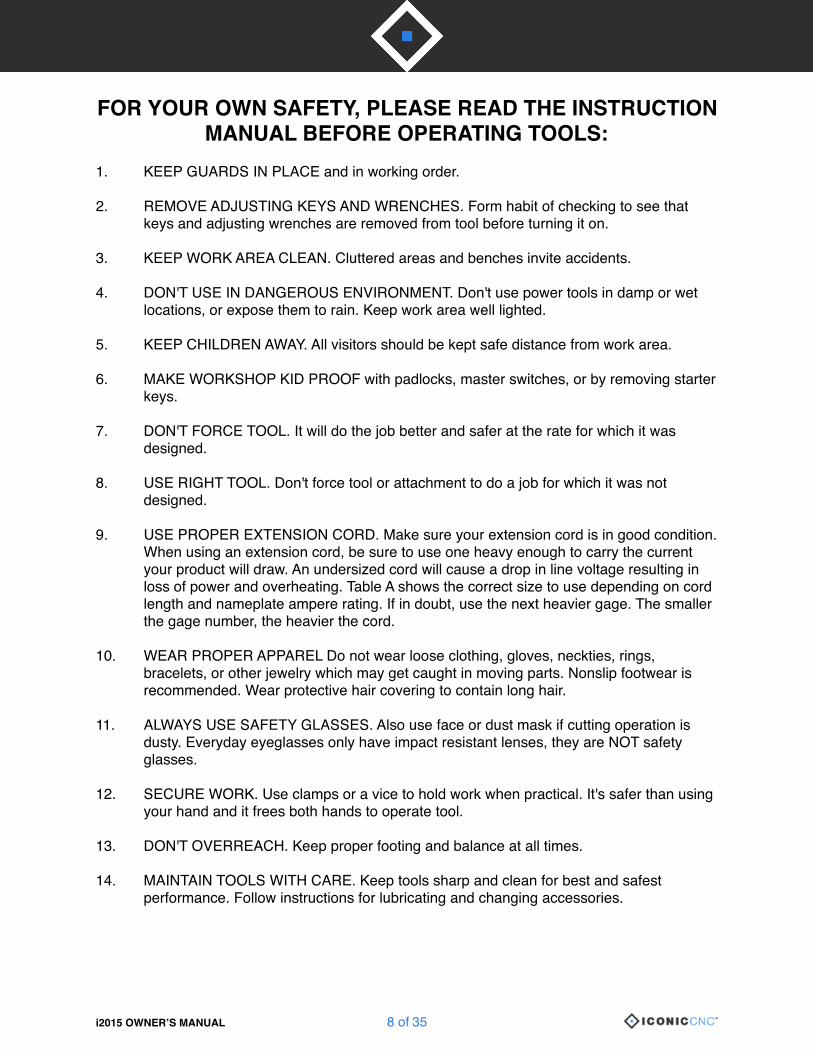
FOR YOUR OWN SAFETY, PLEASE READ THE INSTRUCTION MANUAL BEFORE OPERATING TOOLS:
1. KEEP GUARDS IN PLACE and in working order.
2. REMOVE ADJUSTING KEYS AND WRENCHES. Form habit of checking to see that keys and adjusting wrenches are removed from tool before turning it on.
3. KEEP WORK AREA CLEAN. Cluttered areas and benches invite accidents.
4. DON'T USE IN DANGEROUS ENVIRONMENT. Don't use power tools in damp or wet locations, or expose them to rain. Keep work area well lighted.
5. KEEP CHILDREN AWAY. All visitors should be kept safe distance from work area.
6. MAKE WORKSHOP KID PROOF with padlocks, master switches, or by removing starter keys.
7. DON'T FORCE TOOL. It will do the job better and safer at the rate for which it was designed.
8. USE RIGHT TOOL. Don't force tool or attachment to do a job for which it was not designed.
9. USE PROPER EXTENSION CORD. Make sure your extension cord is in good condition. When using an extension cord, be sure to use one heavy enough to carry the current your product will draw. An undersized cord will cause a drop in line voltage resulting in loss of power and overheating. Table A shows the correct size to use depending on cord length and nameplate ampere rating. If in doubt, use the next heavier gage. The smaller the gage number, the heavier the cord.
10. WEAR PROPER APPAREL Do not wear loose clothing, gloves, neckties, rings, bracelets, or other jewelry which may get caught in moving parts. Nonslip footwear is recommended. Wear protective hair covering to contain long hair.
11. ALWAYS USE SAFETY GLASSES. Also use face or dust mask if cutting operation is dusty. Everyday eyeglasses only have impact resistant lenses, they are NOT safety glasses.
12. SECURE WORK. Use clamps or a vice to hold work when practical. It's safer than using your hand and it frees both hands to operate tool.
13. DON'T OVERREACH. Keep proper footing and balance at all times.
14. MAINTAIN TOOLS WITH CARE. Keep tools sharp and clean for best and safest performance. Follow instructions for lubricating and changing accessories.
i2015 OWNER’S MANUAL � of �8 35�

Safety Guidelines (Cont.)15. DISCONNECT TOOLS before servicing; when changing accessories, such as blades,
bits, cutters, and the like.
16. REDUCE THE RISK OF UNINTENTIONAL STATING. Make sure switch is in off position before plugging in.
17. USE RECOMMENDED ACCESSORIES. Consult the owner's manual for recommended accessories. The use of improper accessories may cause risk of injury to persons.
18. NEVER STAND ON TOOL Serious injury could occur if the tool is tipped or if the cutting tool is unintentionally contacted.
19. CHECK DAMAGED PARTS. Before further use of the machine, a guard or other part that is damaged should be carefully checked to determine that it will operate properly and perform its intended function - check for alignment of moving parts, binding of moving parts, breakage of parts, mounting, and any other conditions that may affect its operation. A guard or other part that is damaged should be properly repaired or replaced.
20. DIRECTION OF FEED. Feed work into a blade or cutter against the direction of rotation of the blade or cutter only.
21. NEVER LEAVE TOOL RUNNING UNATTENDED. TURN POWER OFF. Don't leave tool until it comes to a complete stop.
22. NO ADJUSTMENT SHOULD BE MADE UNTIL THE TOOL HAS BEEN STOPPED.
23. Keep the hands off cutting bit when the tool is operating.
24. Wear eye protection at all times.
(Table A)
Ampere Rating Volts Total Length of Cord (in Feet)
120 25 50 100 150
240 50 100 150 300
More Than Not More Than Minimum Gage for Cord
0 6 18 16 16 14
6 10 18 16 14 12
10 12 16 16 14 12
12 16 14 12 Not Recommended
i2015 OWNER’S MANUAL � of �9 35�

Grounding Instructions1. All grounded, cord-connected tools: In the event of a malfunction or breakdown, grounding provides a path of least resistance for electric current to reduce the risk of electric shock. This tool is equipped with an electric cord having an equipment-grounding conductor and a grounding plug. The plug must be plugged into a matching outlet that is properly installed and grounded in accordance with all local codes and ordinances.Do not modify the plug provided - if it will not fit the outlet, have the proper outlet installed by a qualified electrician.
Improper connection of the equipment-grounding conductor can result in a risk of electric shock. The conductor with insulation having an outer surface that is green with or without yellow stripes is the equipment-grounding conductor. If repair or replacement of the electric cord or plug is necessary, do not connect the equipment-grounding conductor to a live terminal. Check with a qualified electrician or service personnel if the grounding instructions are not completely understood, or if in doubt as to whether the tool is properly grounded.Use only 3-wire extension cords that have 3-prong grounding plugs and 3 pole receptacles that accept the tool's plug. Repair or replace damaged or worn cord immediately.
2. Grounded, cord-connected tools intended for use on a supply circuit having a nominal rating less than 150 volts: This tool is intended for use on a circuit that has an outlet that looks like the one illustrated in Sketch A in Fig. 1. The tool has a grounding plug that looks like the plug illustrated in Sketch A in Fig. 1. A temporary adapter, which looks like the adapter illustrated in Sketch B and C, may be used to connect this plug to a 2 pole receptacle as shown in Sketch B if a properly grounded outlet is not available. The temporary adapter should be used only until a properly grounded outlet can be installed by a qualified electrician. This adapter is not permitted in Canada. The green-coloured rigid ear, lug, and the like, extending from the adapter must be connected to a permanent ground such as a properly grounded outlet box.
(Fig. 1)
i2015 OWNER’S MANUAL � of �10 35�

Hazardous Areas
i2015 OWNER’S MANUAL � of �11 35�

Machine Components
i2015 OWNER’S MANUAL � of �12 35�
No. Description No. Description
1 Z-Axis Stepper Motor 9 Z- Limit Switch
2 X-Axis Stepper Motor 10 Y- Limit Switch
3 Brushless DC Spindle Motor 11 Y+ Limit Switch
4 Y-Axis Stepper Motor 12 X- Limit Switch
5 USB Port 13 X+ Limit Switch
6 Main Power 14 Z-Axis Auto Tool Indexer
7 Emergency Stop Button 15 Tool Bit Change Safety Button
8 Z+ Limit Switch

Unpacking Your ICONICCNC MachinePlease unpack your CNC machine with care. It should be removed from the packaging and set on a sturdy surface using the handle on the sides of the machine, which will require two individuals. The i2015 comes fully assembled, and is ready for operation once the Owner’s Manual has been read. This machine was designed for wood and plastic carving only. Warranty voids if users intend to carve or metal (or other non-approved) material.
All instructions and tutorials for your i2015 CNC machine can be found on our website (www.iconiccnc.com) under the Training Videos section.
i2015 OWNER’S MANUAL � of �13 35�

Decibel Levels1. When machine is under dry run operation, decibel level should be <85db.
2. Decibel is measured from the front of the machine, in which the operator‘s distance to the spindle should be approximately 50cm. Measured Front, Back, Right, and Left of the machine.
Machine Structure X, Y & Z-Axis Ball Screw Transmissions are driven by 3-Phase Stepper Motors. X & Z Axis Drive with Couplers, and the Y-Axis drivers with a Timing Belt (to reduce machine’s overall size)
Spindle system is built with 20,000 RPM high-speed Brushless DC Spindle Motor. It is capable of operating continuously for several hours without the need to stop, or extra cooling.
Electrical Systems & Controls1. Control System: Composed of Control Circuit Board.
2. Power System: Composed of Power Supply.
3. Transmission System: Composed of Spindle Circuit Board.
4. HMI (Human Machine Interface): For machine operation.
i2015 OWNER’S MANUAL � of �14 35�

X, Y, Z Movements
X+ Moves Spindle to the RightX- Moves Spindle to the LeftZ+ Moves Spinde UpZ- Moves Spindle DownY+ Moves Spindle BackwardsY- Moves Spindle Forwards
Installing Cutting Tools
1. Press round pin.2. Lock cutting tool nut
manually.3. Insert tool into the net.4. Lock down the nut manually
until bit is secure.5. Secure nut tightly with
open-end wrench.6. Follow these instructions to
remove bits.
i2015 OWNER’S MANUAL � of �15 35�

Standard Tooling
Tool Box Contents1. Conical Bit 2. End Mill3. 60° V-Bit 4. 90° V-Bit5. 1/4” Collet Nut 6. 1/2” Collet Nut7. Open-End Wrench (11mm x 13mm) 8. Double-Ended Screw Driver9. Open-End Wrench (22mm x 24mm) 10. Brush11. 3D Greyscale Image Library DVD 12. USB Stick (with iPicture Software)
i2015 OWNER’S MANUAL � of �16 35�
Tool Description Suitable For
Conical Bit
1/4” (6mm) R = 0.8mm
Carving 3D modelsProjects with fine details
End Mill
1/4” (6mm) D = 3.2mm
Area ClearancesCutting out individual parts
�
�
Tool Description Suitable For
60° V-Bit
1/4” (6mm) 60 Degrees
Sign-making Decorative machining
90° V-Bit
1/2” (12mm) 90 Degrees
Sign-making Decorative machining
�
�

Setting Up A Project1. Plug in your USB Stick, which contains your G-Code files. Turn on machine’s power. A
welcome message will appear on the LCD Screen; press the Enter key on your Keypad, which will move the Spindle to its default Home Position. Handheld controller will ask you to confirm that there is a USB Stick inserted. Press Enter to continue.
2. The LCD screen will display the Main Menu. Move the cursor to Select File, and press Enter to browse the files located on your USB Stick.
3. Browse the USB directory (which is able to display 48 files max.), move the cursor to select the desired file, and press Enter.
4. Choose Manual Jog Mode to set your Position of Origin.
5. Using the X+, X-, Y+, Y-, Z+, Z- keys, move the Spindle on the 3 Axis’ to set your Position of Origin (the tool should be touching the top of the material on the Z Axis).
6. Move the cursor to Enter to set ORG, and press Enter to set the new Position of Origin.
7. Coordinates Confirmation message will pop up. Mark these coordinates down if you are running the same operation multiple times, or if you are using a multi-tool operation. Refer to “Repeating Origin Setting” in this Manual. Press Enter to continue. All values should change to 0.0mm, indicating that this is the new Position of Origin.
8. Press Back on your handheld controller to proceed.
9. If you would like, you may choose to use the Border function (not required), which will run a simulation of the projects dimensions, to ensure that your project will not hit a limit switch or go beyond your material size.
10. Select Process to begin machine operation. Move the cursor to select machining speed:
11. Operation will begin by going through Z-Axis Auto Indexer process (see Page 20).Please follow Safety Instructions, and ensure that your material is properly secured to the table.
i2015 OWNER’S MANUAL � of �17 35�
Speed Default Feedrate Spindle Speed Suitable For
Smart Low 600mm/min 20,000 RPM Hard Materials, 5-8mm Depth Per Pass
Smart Normal 2,400mm/min 20,000 RPM Router/Raster Carving, 3-5mm Depth
Smart High 4,800mm/min 20,000 RPM Soft Materals, 0-3mm Depth
Custom Speed
600 - 6,000mm/min (Parameter must be set in G-Code file)
6,000 - 20,000 RPM (Parameter must be set in G-Code file)
Advanced machining

Using On-Board SD Card StorageTo avoid accidental USB disconnection during operation, users may choose to transfer their G-Code files from the USB Stick to the Onboard SD Card.
1. Plug in your USB Stick, which contains your G-Code files. Turn on machine’s power. A welcome message will appear on the LCD Screen; press the Enter key on your Keypad, which will move the Spindle to its default Home Position.Handheld controller will ask you to confirm that there is a USB Stick inserted. Press Enter to continue.
2. The LCD screen will display the Main Menu. Move the cursor to Select File, and press Enter to browse the files located on your USB Stick.
3. Locate the desired file, and press the Y+ key to save the file to the SD Card.
4. Upon completion, move the cursor to Configuration, and press Enter, followed by System Setting.
5. Move the cursor to Disk:USB, and press Enter. The cursor will become a solid block, indicating that this option has been selected; press the Down button to change to Disk:SD.
6. Press Back to confirm selection, and move the cursor down to select Save. Press Enter to save these settings.
7. USB Stick can be safely removed.
8. Move the cursor to Select File, and press Enter to browse the files located on the SD Card. To delete these files, simply move the cursor to the appropriate file name, and press the Y- key to delete.
Repeating Position Of Origin SettingWhen carving the same project multiple times, users may choose to re-use a Position of Origin, rather than manually setting it each time. There are two options available.
1. From the Main Menu on your handheld controller, select Configuration, followed by Reset To Origin. Select Work Coordinate. The LCD will display the last-used Position of Origin. Press Enter To Continue to repeat the origin setting. (Selecting Machine Coordinate within this menu will reset the machine to its default Position of Origin.)
2. From the Main Menu on your handheld controller, select Position, followed by Coordinate Mode. Select the desired Axis to adjust, and press Enter. The cursor will turn to a solid block, indicating that it is ready to set its coordinates. Press the Up/Down keys to input the coordinate setting. Once completed, press Back, and select Move and Set ORG.
i2015 OWNER’S MANUAL � of �18 35�
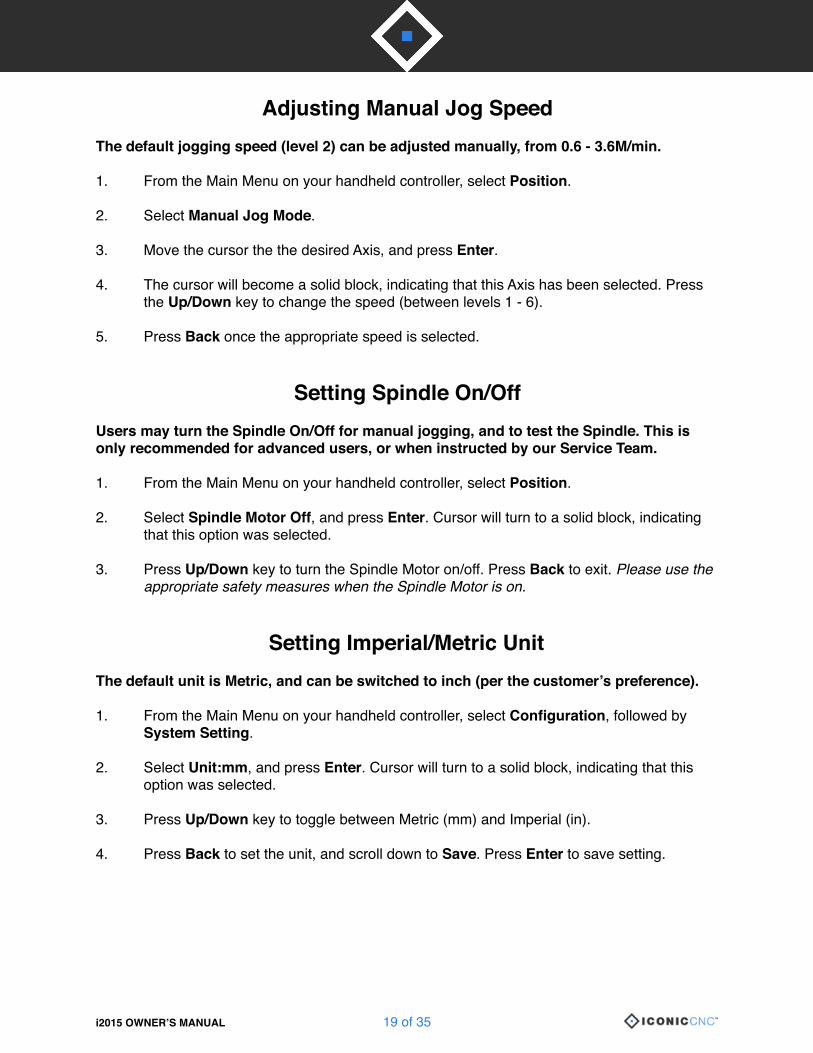
Adjusting Manual Jog SpeedThe default jogging speed (level 2) can be adjusted manually, from 0.6 - 3.6M/min.
1. From the Main Menu on your handheld controller, select Position.
2. Select Manual Jog Mode.
3. Move the cursor the the desired Axis, and press Enter.
4. The cursor will become a solid block, indicating that this Axis has been selected. Press the Up/Down key to change the speed (between levels 1 - 6).
5. Press Back once the appropriate speed is selected.
Setting Spindle On/Off Users may turn the Spindle On/Off for manual jogging, and to test the Spindle. This is only recommended for advanced users, or when instructed by our Service Team.
1. From the Main Menu on your handheld controller, select Position.
2. Select Spindle Motor Off, and press Enter. Cursor will turn to a solid block, indicating that this option was selected.
3. Press Up/Down key to turn the Spindle Motor on/off. Press Back to exit. Please use the appropriate safety measures when the Spindle Motor is on.
Setting Imperial/Metric UnitThe default unit is Metric, and can be switched to inch (per the customer’s preference).
1. From the Main Menu on your handheld controller, select Configuration, followed by System Setting.
2. Select Unit:mm, and press Enter. Cursor will turn to a solid block, indicating that this option was selected.
3. Press Up/Down key to toggle between Metric (mm) and Imperial (in).
4. Press Back to set the unit, and scroll down to Save. Press Enter to save setting.
i2015 OWNER’S MANUAL � of �19 35�

Activating Safety Enclosure SensorWhen the Safety Enclosure is chosen (optional accessory), users may Activate/Deactivate the Safety Enclosure Sensor. When the sensor is activated, the Spindle Motor will come to an immediate stop when the enclosure is lifted. To resume machine operation, the enclosure must be properly closed again. If there is no Safety Enclosure installed on the machine, the sensor setting should remain Off at all times.
1. From the Main Menu on your handheld controller, select Configuration, followed by System Setting.
2. Select Cover:Off, and press Enter. Cursor will turn to a solid block, indicating that this option was selected.
3. Press Up/Down key to toggle between Cover:On and Cover:Off.
4. Press Back to set the unit, and scroll down to Save. Press Enter to save setting.
Z-Axis Auto Indexer & Tool-Change SafetySome projects may require multiple tools, and the user will need to change the tool mid-operation. The i2015 comes with a Z-Axis Auto Indexer, which will automatically measure the length of the tools, to avoid having to reset the Z-Axis Position of Origin during operation. The machine is also equipped with a Tool-Change Safety switch, to prevent accidental injury to a tool change.
1. Begin your G-Code operation, using standard machine operation procedures. The machine will identify that there are multiple tools in the G-Code. Machine will begin operation by moving to the Z-Axis Auto Indexer to measure the first tool. It will request that you ensure that the Auto Indexer is clean. Press Down and choose Continue.
2. The Spindle will move to the center of the table, ready for tool change. The machine will go through the following process for each tool, including the first tool, though it is not required that you change the tool initially. A message will pop up to remind the user to turn on the Tool Change Safety switch. Choose Yes once the switch is set to On, and press Enter. Please ensure that the switch is turned on, which will cut power from the Spindle Motor, prior to tool change.
3. The LCD will display the name of the next required tool. With the Tool Change Safety switch set to On, it is now safe to replace the tool (expect for the first tool, which should already be installed). Once properly installed, press Continue.
4. A message will pop up to remind the user to turn off the Tool Change Safety switch. Choose Yes once the switch is set to Off, and press Enter. The Spindle will not be able to activate for operation unless the switch is turned off.
5. Repeat process as necessary, based on the number of tool changes required.
i2015 OWNER’S MANUAL � of �20 35�

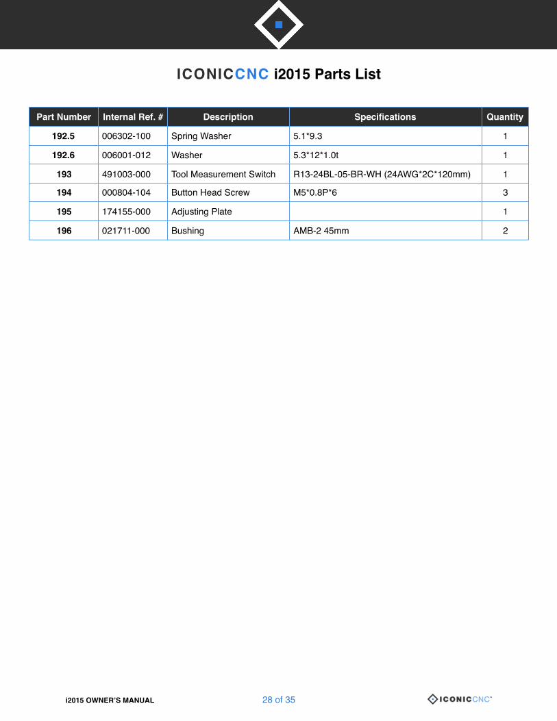
ICONICCNC i2015 Parts List
i2015 OWNER’S MANUAL � of �21 35�
Part Number Internal Ref. # Description Specifications Quantity
1 490777-000 LED (Green) 1
2 490778-000 LED (Right) 1
4 000303-101 Phillips Head Screw M5*0.8P*6 11
5 280182-000 Spring 1
6 251083-615 Spindle Front Cover 1
7 360931-908 Pin 1
8 000303-103 Phillips Head Screw M5*0.8P*10 26
9 172744-902 Steel Plate 1
10 000103-103 CAP Screw M6*1.0P*12 23
11 Complete 924084-000 Collet Complete
11.1 381044-000 Conical Bit R1/32” x 1” x 1/4” x 2.36L 1
11.2 381020-000 End Mill Bit D1/8” x 0.47” x 1/4” x 2.36L 1
11.3 230394-000 Collet Nut Ø1/4” 1
11.4 230378-000 Collet Nut Ø1/2” 1
11.5 381285-000 60 Degree V-Bit 6.35x60°*60L 1
11.6 381286-000 90 Degree V-Bit 12.7x90°*60L 1
12 Complete FM01-53 Spindle Complete
12.1 910116-000 BLDC 120V Motor BLDC-60(6000~20000rpm) 1
12.2 490986-000 Spindle Driver Board DBL-A11CA11600-C03-A 1
12.3 490955-000 Power Supply (PMT-24V150W1AA) 1
13 022501-001 KCF-130-B Cable Clamp KCF-130-B 1
14 000301-202 Phillips Head Screw M3*0.5P*12 1
15 490781-000 Terminal Block PA-8DS 1
16 000302-102 Phillips Head Screw M4*0.7P*8 33
17 006501-200 Sprocket Washer 4.3*8.5(BW-4) 10
ICONICCNC i2015 Parts List
i2015 OWNER’S MANUAL � of �22 35�
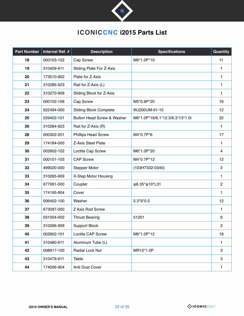
Part Number Internal Ref. # Description Specifications Quantity
18 000103-102 Cap Screw M6*1.0P*10 11
19 310459-911 Sliding Plate For Z-Axis 1
20 173510-902 Plate for Z-Axis 1
21 310285-923 Rail for Z-Axis (L) 1
22 310270-909 Sliding Block for Z-Axis 1
23 000102-106 Cap Screw M5*0.8P*20 16
24 922494-000 Sliding Block Complete WJ200UM-01-10 12
25 029402-101 Button Head Screw & Washer M6*1.0P*16/6.1*12.3/6.3*13*1.0t 32
26 310284-923 Rail for Z-Axis (R) 1
28 000302-201 Phillips Head Screw M4*0.7P*6 17
29 174184-000 Z-Axis Steel Plate 1
30 002602-102 Loctite Cap Screw M6*1.0P*20 4
31 000101-103 CAP Screw M4*0.7P*12 12
32 499020-000 Stepper Motor (103H7332-0340) 3
33 310265-909 X-Step Motor Housing 1
34 677061-000 Coupler ψ6.35*ψ10*L31 2
35 174195-904 Cover 1
36 006402-100 Washer 5.3*9*0.5 12
37 673097-000 Z Axis Rod Screw 1
38 031004-002 Thrust Bearing 51201 6
39 310266-909 Support Block 2
40 002602-101 Loctite CAP Screw M6*1.0P*12 18
41 310480-911 Aluminum Tube (L) 1
42 008917-100 Radial Lock Nut MR12*1.0P 3
43 310479-911 Table 3
44 174006-904 Anti Dust Cover 1
ICONICCNC i2015 Parts List
i2015 OWNER’S MANUAL � of �23 35�
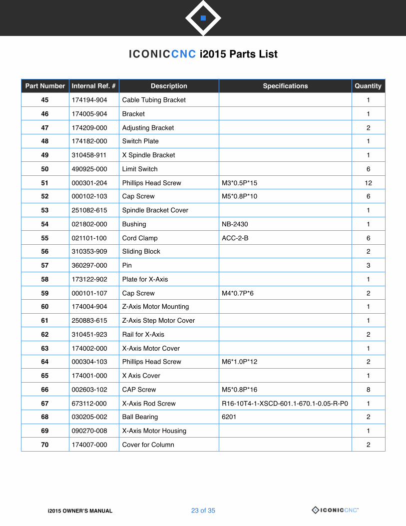
Part Number Internal Ref. # Description Specifications Quantity
45 174194-904 Cable Tubing Bracket 1
46 174005-904 Bracket 1
47 174209-000 Adjusting Bracket 2
48 174182-000 Switch Plate 1
49 310458-911 X Spindle Bracket 1
50 490925-000 Limit Switch 6
51 000301-204 Phillips Head Screw M3*0.5P*15 12
52 000102-103 Cap Screw M5*0.8P*10 6
53 251082-615 Spindle Bracket Cover 1
54 021802-000 Bushing NB-2430 1
55 021101-100 Cord Clamp ACC-2-B 6
56 310353-909 Sliding Block 2
57 360297-000 Pin 3
58 173122-902 Plate for X-Axis 1
59 000101-107 Cap Screw M4*0.7P*6 2
60 174004-904 Z-Axis Motor Mounting 1
61 250883-615 Z-Axis Step Motor Cover 1
62 310451-923 Rail for X-Axis 2
63 174002-000 X-Axis Motor Cover 1
64 000304-103 Phillips Head Screw M6*1.0P*12 2
65 174001-000 X Axis Cover 1
66 002603-102 CAP Screw M5*0.8P*16 8
67 673112-000 X-Axis Rod Screw R16-10T4-1-XSCD-601.1-670.1-0.05-R-P0 1
68 030205-002 Ball Bearing 6201 2
69 090270-008 X-Axis Motor Housing 1
70 174007-000 Cover for Column 2

ICONICCNC i2015 Parts List
i2015 OWNER’S MANUAL � of �24 35�
Part Number Internal Ref. # Description Specifications Quantity
71 001802-102 CAP with Spring Wahser M6*1.0P*20/6.1*12.3 8
72 006001-022 Washer 6.3*13*1.0t 10
73 011103-105 Pin 5*12 1
74 090272-008 Left Column 1
75 173190-000 Cover for Beam 2
76 923979-000 Chain for X-Axis (24-links) 1
77 000401-201 Countersunk Screw M4*0.7P*8 8
78 174003-904 Chain Bracket for X-Axis 1
79 310449-911 Beam 1
80 021709-000 Cord Protector AMB-3 60mm 1
81 021708-000 Cord Protector AMB-3 80mm 1
82 200096-615 Foam 60*20*1t 1
83 090271-008 Right Column 1
84 008006-100 Hexagon Nut M8*1.25P(13B*6.5H) 4
85 174193-904 Tool Measurement Plate 1
86 001601-101 Phillips Head Screw/Washer M4*0.7P*8/4*10*0.8t 6
87 230049-000 Foot Pad Screw 4
88 250123-615 Carry Handle 4
89 174179-000 Base 1
90 000104-108 CAP Screw M8*1.25P*25 8
91 008002-200 Hexagon Nut M4*0.7P(7B*3.2H) 2
92 200098-615 Foam 789*10*2.0mm 1
93 174181-000 Panel for Electrical Box 1
94 174183-000 Cover for Electrical Box 1
95 Complete 923027-000 Clamp Assembly Complete 4
95.1 130275-903 Clamp Bracket 1

ICONICCNC i2015 Parts List
i2015 OWNER’S MANUAL � of �25 35�
Part Number Internal Ref. # Description Specifications Quantity
95.2 173010-902 Clamp Nut SPHC 1
95.3 000303-112 Phillip Head Screw M5*0.8P*18 1
95.4 006302-100 Spring Washer 5.1*9.3 1
95.5 000304-107 Phillips Head Screw M6*1.0P*16 1
99 174051-902 Wire plate 2
100 015207-000 Belt for Gear 3GT-312-12 1
101 173243-902 Plate for Y-Axis 1
102 021706-000 Cord Proctector AMB-1.6 60mm 1
103 174180-000 Linkage for Y-Axis 1
104 174161-000 Y-Axis Steel Plate 1
105 673111-000 Y-Axis Rod Screw R16-10T4-1-XSCD-468.6-551.6-0.05-R-P0 1
106 012002-007 Key 4*4*20 1
107 310377-909 Bearing Seat 1
108 310378-909 Bearing Seat 1
109 010102-000 R Ring RTW-32 1
110 190218-902 Bushing 1
111 001901-101 SET Screw M5*0.8P*5 4
112 310391-909 Timing Pulley 1
113 173535-902 Belt Plate 2
114 310450-923 Rail for Y-Axis 2
116 021375-000 Cord Clamp MGB16-10B 1
120 006317-100 Spring Washer 6.1*10.3 3
121 173999-904 Y-Axis Motor Mounting 1
122 008301-100 Loctite Nut M4*0.7P(7B*5H) 4
123 310454-909 Motor Pulley 1
124 174000-904 Belt Adjusting Plate 1

ICONICCNC i2015 Parts List
i2015 OWNER’S MANUAL � of �26 35�
Part Number Internal Ref. # Description Specifications Quantity
125 008005-100 Hexagon Nut M6*1.0P(10B*5H) 1
126 000002-105 Hexagon Screw M6*1.0P*25 1
127 021107-100 Cord Clamp ACC-1.5-B 8
129 923978-000 Chain for Y-Axis (18-links) 1
138 250144-615 Cable Clamp 2
139 000801-108 Button Head Screw M6*1.0P*8 4
142 000301-201 Phillips Head Screw M3*0.5P*6 4
143 490964-000 EMC Filter 15" 1
144 491010-000 Circuit Board Support (BS-28S) 4
145 000302-109 Button Head Screw M4*0.7P*25 4
146 490779-000 Fan DC 24V 2.04W 1
147 250895-615 Fan Cover ABS 1
149 048300-002 Button Head Screw M3*0.5P*6 AS306A 2
150 200080-000 Foam 180*10*0.5t 2
151 000302-101 Button Head Screw M4*0.7P*6 6
152 491004-000 Insulated Cable Socket 2525S*430mm 2
153 Complete FM01-58 Controller Assembly Complete
153.1 924266-000 Controller 1
153.2 490958-003 HMI Board 20" 1
153.3 490762-000 LCD Display WH2004A 1
156 022501-002 Cable Clamp WE core 742 711 31 1
157 022501-003 Cable Clamp WE core 742 712 22 1
160 490915-000 Power Switch HY52 1
161 490820-000 Emergency Stop (ALE16) 1
163 023702-002 Cable Glands MGB16-07B 1
164 490652-000 USB USB (MLC) 1
165 174008-904 Controller Holder 1
166 250873-615 Controller Lower Cover 1

ICONICCNC i2015 Parts List
i2015 OWNER’S MANUAL � of �27 35�
Part Number Internal Ref. # Description Specifications Quantity
167 001202-602 Self Tapping Screw M3*1.06P*6 4
168 001106-601 Self Tapping Screw M2*0.63P*6L 4
169 Complete 923343-000 Cover for Right Column 1
169.1 250860-615 Right Cover 1
169.2 573676-000 Display Label 1
169.3 573677-000 Controller Key Label 1
170 001201-701 Self Tapping Screw M4*1.59P*12L 4
171 021010-000 Cable Tie ALT-150M-B 5
172.1 453013-020 Cord w CSA/UL Plug SJT 16AWG*3C*3000mm 1
175 478057-001 Wire 26AWG*8C*1030mm(11*25*67cm) 1
176 660175-000 Tool Box 220*145*48 1
177 040401-000 Screw Driver 1*75 1
178 040203-000 Open Wrench 11*13 1
179 040207-000 Open Wrench 22*24 1
180 660179-000 Brush 125*54*40 1
181 250436-615 Packaging Protector 4
182 500050-300 Styrofoam Bar 1
185 610004-048 Pallete 920x908x134 1
187 540335-000 Carton for Controller 140mm*46mm*210mm 1
188 520001-762 Carton for Toolbox 220mm*145mm*125mm 1
189 491026-000 Switch YW1S-2E11(IDEC) 1
190 029201-101 Button Head Screw/Washer M6*1.0P*12/6.6*13*1.0t 2
191 002603-105 Loctite CAP Screw M5*0.8P*20 4
192 Complete 924133-000 Front & Rear Clamp Set 2
192.1 130324-903 Front & Rear Clamp Brackets 1
192.2 173010-902 Clamp Nut SPHC 1
192.3 000303-112 Phillips Head Screw M5*0.8P*18 1
192.4 000304-107 Phillips Head Screw M6*1.0P*16 1
ICONICCNC i2015 Parts List
i2015 OWNER’S MANUAL � of �28 35�
Part Number Internal Ref. # Description Specifications Quantity
192.5 006302-100 Spring Washer 5.1*9.3 1
192.6 006001-012 Washer 5.3*12*1.0t 1
193 491003-000 Tool Measurement Switch R13-24BL-05-BR-WH (24AWG*2C*120mm) 1
194 000804-104 Button Head Screw M5*0.8P*6 3
195 174155-000 Adjusting Plate 1
196 021711-000 Bushing AMB-2 45mm 2

Electrical Schematic Diagram
i2015 OWNER’S MANUAL � of �29 35�
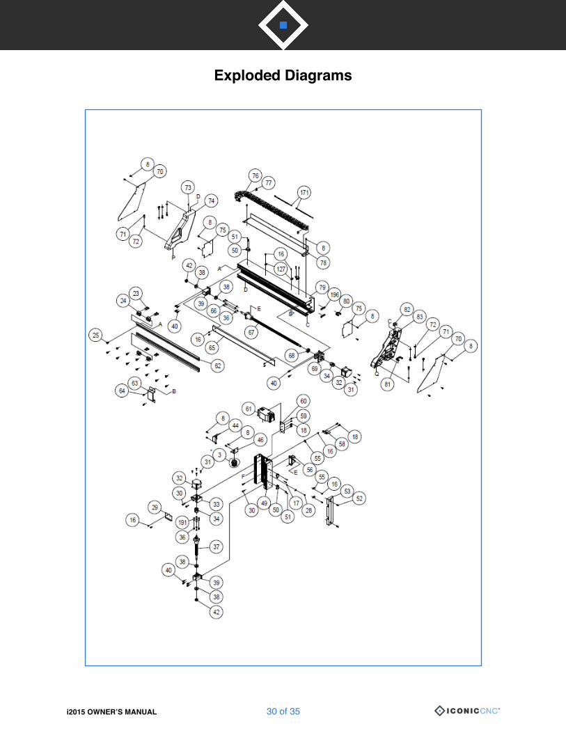
Exploded Diagrams
i2015 OWNER’S MANUAL � of �30 35�

Exploded Diagrams (Cont.)
i2015 OWNER’S MANUAL � of �31 35�
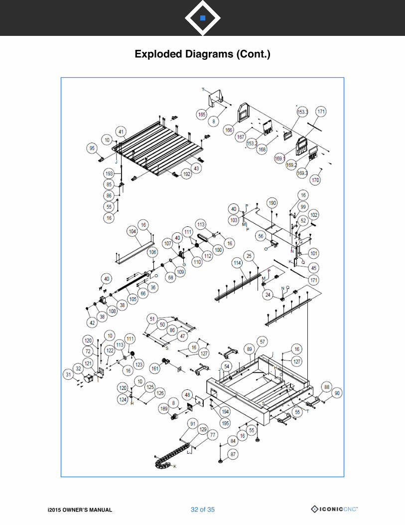
Exploded Diagrams (Cont.)
i2015 OWNER’S MANUAL � of �32 35�

Exploded Diagrams (Cont.)
i2015 OWNER’S MANUAL � of �33 35�

Exploded Diagrams (Cont.)
i2015 OWNER’S MANUAL � of �34 35�

Contact Information
i2015 OWNER’S MANUAL � of �35 35�