table of contents - igvc
TRANSCRIPT
1
Table of Contents 1. Overview ..................................................................................................................................... 2
1.1 Design Process .................................................................................................................................... 2
2. Mechanical Design...................................................................................................................... 3 2.1. Chassis ............................................................................................................................................... 3
2.2. Drivetrain ....................................................................................................................................... 4
2.3. Weatherproofing ................................................................................................................................ 5
2.4. Rear Mount ........................................................................................................................................ 5
2.5. Suspension ......................................................................................................................................... 6
3. Electrical Design ......................................................................................................................... 6 3.1. Power Source and Distribution .......................................................................................................... 6
3.2. Devices ............................................................................................................................................... 7
3.2.1 Roboteq AX2550 Motor Controller ............................................................................................. 7
3.2.2 Emergency Stop ........................................................................................................................... 7
3.2.3 On-board Computer ..................................................................................................................... 8
3.2.4 Other Components of Interest ...................................................................................................... 9
3.3. Overall Design Decisions .................................................................................................................. 9
3.3.1 Layout ........................................................................................................................................ 10
3.3.2 Power Distribution ..................................................................................................................... 10
3.3.3 Component Usage ...................................................................................................................... 10
4. Software .................................................................................................................................... 11 4.1 Overview ........................................................................................................................................... 11
4.2 Sensors .............................................................................................................................................. 11
4.2.1 LIDAR ....................................................................................................................................... 11
4.2.2 Camera ....................................................................................................................................... 12
4.2.3 IMU ............................................................................................................................................ 12
4.2.4 GPS ............................................................................................................................................ 12
4.2.5 Ultrasonic Sensor Array ............................................................................................................. 12
4.3 Program Hierarchy ............................................................................................................................ 12
4.3.1 Low Level Functions ................................................................................................................. 12
4.3.2 Medium Level Functions ........................................................................................................... 13
4.3.3 High Level Functions ................................................................................................................. 14
6. Conclusion ................................................................................................................................ 15
2
1. Overview The Stony Brook Robot Design Team is led by an Executive Board consisting of five
administrative positions and three engineering team leaders, all undergraduate students. The
president, vice president, secretary, treasurer and public relations officer collaborate to take care of
the team logistics while the mechanical, electrical and software engineering team leaders oversee the
design, fabrication and testing of the competition vehicle. The team leaders report directly to the
vice president. The overall hierarchy is shown in Figure 1.
Figure 1: Team leadership structure
Each vehicle prepared for competition is a collaborative effort. Although P15 was entered
into last year’s competition as P14, a senior design project from the Department of Mechanical
Engineering at Stony Brook University, we have rebuilt some parts and completely retrofitted its
interior.
1.1 Design Process A five stage design process was used to design, manufacture, and test our robot. The first step
in the design process was competition research. Product Design Specifications (PDS) were created to
define the key requirements of the robot. Research and parametric analysis was done on prior robots
that competed in IGVC to get a better idea of qualities that we would want in our own robot.
The second step was conceptual design. All possible designs were generated and compared
by using a set of criteria. An iterative process allowed for the best design to be developed. The third
step was detailed design. Sections 2, 3, and 4 will describe the mechanical, electrical and software
aspects of the detailed design phase respectively. Each component was justified by a Component
Design Specifications (CDS).

3
The fourth stage is centered on building the robot. Most of the fabrication was done in a four
week period. Examples of machinery that were used include a milling machine, lathe, band saw, and
rapid prototype machine. The fifth stage was to test and debug the robot in a systematic manner.
Sensors were progressively
integrated until every sensor had
been added and was working
properly. Even though each step had
specific guidelines and requirements;
each task was not done
independently. Often, it became
necessary to return to previous steps to modify the system. Graphically, this process is shown in
Figure 2.
2. Mechanical Design
2.1. Chassis The chassis of the robot is built from extruded aluminum. The extruded aluminum is easily
assembled using right angle brackets, which makes the
robot more modular. and easy to change or add
parts. In order of to decrease the degrees of freedom as
well as increase the strength of the design, the
aluminum was milled to have notches, which fit into
the channels on other adjacent structural members.
Figure 3 shows a CAD drawing of the designed
structure.
The second goal was to analyze each
component. This was done with Finite Element Analysis (FEA), using Autodesk Inventor. FEA was
done on each component designed that would be placed under loading conditions. Special
consideration was given to: the locations of stresses, displacement, and factor of safety. An example
of this is shown in Figure 4 on the next page. Here, the deflection of the moment arm is considered.
Figure 2: Design Process Flowchart
Figure 3: CAD Drawing
4
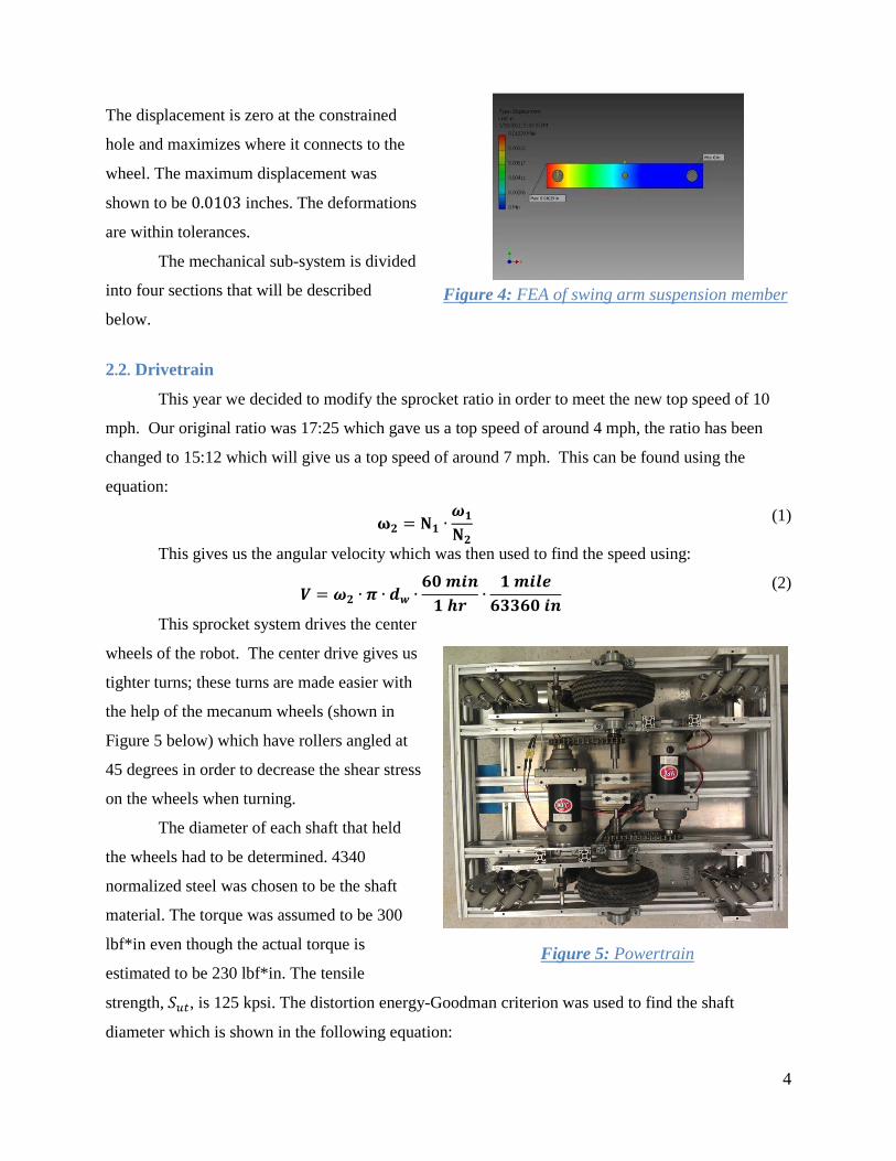
The displacement is zero at the constrained
hole and maximizes where it connects to the
wheel. The maximum displacement was
shown to be 0.0103 inches. The deformations
are within tolerances.
The mechanical sub-system is divided
into four sections that will be described
below.
2.2. Drivetrain
This year we decided to modify the sprocket ratio in order to meet the new top speed of 10
mph. Our original ratio was 17:25 which gave us a top speed of around 4 mph, the ratio has been
changed to 15:12 which will give us a top speed of around 7 mph. This can be found using the
equation:
𝛚𝟐 = 𝐍𝟏 ∙𝝎𝟏
𝐍𝟐 (1)
This gives us the angular velocity which was then used to find the speed using:
𝑽 = 𝝎𝟐 ∙ 𝝅 ∙ 𝒅𝒘 ∙𝟔𝟎 𝒎𝒊𝒏𝟏 𝒉𝒓 ∙
𝟏 𝒎𝒊𝒍𝒆𝟔𝟑𝟑𝟔𝟎 𝒊𝒏
(2)
This sprocket system drives the center
wheels of the robot. The center drive gives us
tighter turns; these turns are made easier with
the help of the mecanum wheels (shown in
Figure 5 below) which have rollers angled at
45 degrees in order to decrease the shear stress
on the wheels when turning.
The diameter of each shaft that held
the wheels had to be determined. 4340
normalized steel was chosen to be the shaft
material. The torque was assumed to be 300
lbf*in even though the actual torque is
estimated to be 230 lbf*in. The tensile
strength, 𝑆𝑢𝑡, is 125 kpsi. The distortion energy-Goodman criterion was used to find the shaft
diameter which is shown in the following equation:
Figure 4: FEA of swing arm suspension member
Figure 5: Powertrain

5
𝑑 = (
16𝑛𝜋 (
(4(𝐾𝑓𝑀𝑎)2 + 3(𝐾𝑓𝑠𝑇𝑎)2)12
𝑆𝑒+
(4(𝐾𝑓𝑀𝑚)2 + 3(𝐾𝑓𝑠𝑇𝑚)2)12
𝑆𝑢𝑡))13
(2)
The above equation has several unknowns. The factor of safety, n was found to be 3.3. A
conservative assumption was made that an end-mill keyset ran through the entire shaft. Because of
this distinction: 𝐾𝑓 = 2.14.Another assumption is made that claims that midrange moments and
alternating torques equal 0. In other words: 𝑀𝑚 = 𝑇𝑎 = 0. The shoulder fillet, 𝐾𝑓𝑠, was assumed to
be equaled to 3. The parameter 𝑆𝑒 = 0.5𝑘𝑎𝑘𝑏𝑘𝑐𝑘𝑑𝑘𝑒𝑘𝑓𝑆𝑢𝑡. It was found that 𝑘𝑎 = 𝑎(𝑆𝑢𝑡/1000)𝑏
where a = 2.7 and b = -0.265, 𝑘𝑏 = 0.879𝑑−0.107, and 𝑘𝑐 = 𝑘𝑑 = 𝑘𝑒 = 𝑘𝑓 =1.
Since the diameter the shaft is a component of one of the parameter for its own calculation,
an iterative process had to occur. To speed up this process, a program was written in MATLAB so
that, each iteration could be ran quickly. The optimum diameter was found to be:
d = 1 in.
2.3. Weatherproofing We installed a new weather proofing system, instead of using just plastic to cover the
electronics in the chassis, we now use canvas. This canvas is sprayed with a water proofing spray
with PTEF, which converts the canvas into a hydrophobic surface. In the event of rain, the droplets
will roll off the canvas instead of saturating and permeating it. Using canvas also gave us more room
to mount components of the chassis. With our original design components were only mounted in the
center of the chassis, with the new weather proofing we are able to mount smaller components on the
sides. Along with the canvas covering the top and sides there are plastic plates which cover the front
and back. Each of these plates have four holes where fans are mounted on the inside to allow for
cooling of the components which tend to overheat, such as the motherboard and motor
controller. These fans are oriented so that the flow moves from the front of the robot to the back, the
front fans move air in while the back move air out.
2.4. Rear Mount For components that need to be away from electronic/magnetic interference, such as the
compass and GPS, and for the cameras which needed to see the front of the robot a tower was
assembled. The tower reaches a height of 5 feet which allows the cameras to see not only what is in
front of the robot but also the front of the chassis in order to see its position. In order to minimize the
vibrations on the mount, the GPS and compass are mounted lower.
6
2.5. Suspension In order to minimize vibrations throughout the robot, air shocks are used as suspension. The
air shocks are mounted to the chassis of the robot and an arm which holds the front mecanum wheels
of the robot. The air shocks can be calibrated for the amount of play wanted by the knobs on the
shocks and also by the amount of air added. This year to give the shocks more play we mounted
them high and also angled them off from vertical.
3. Electrical Design The electrical portion of Project 15 can be summarized by the power source, devices and the
design decisions made behind everything.
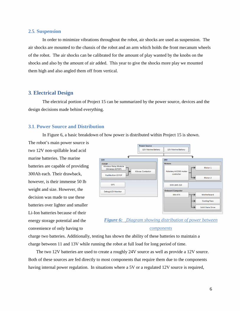
3.1. Power Source and Distribution In Figure 6, a basic breakdown of how power is distributed within Project 15 is shown.
The robot’s main power source is
two 12V non-spillable lead acid
marine batteries. The marine
batteries are capable of providing
300Ah each. Their drawback,
however, is their immense 50 lb
weight and size. However, the
decision was made to use these
batteries over lighter and smaller
Li-Ion batteries because of their
energy storage potential and the
convenience of only having to
charge two batteries. Additionally, testing has shown the ability of these batteries to maintain a
charge between 11 and 13V while running the robot at full load for long period of time.
The two 12V batteries are used to create a roughly 24V source as well as provide a 12V source.
Both of these sources are fed directly to most components that require them due to the components
having internal power regulation. In situations where a 5V or a regulated 12V source is required,
Figure 6: Diagram showing distribution of power between
components
7
small DC-DC converter packs capable of outputting 5V/12V constantly based on variable input are
utilized.
3.2. Devices There are various electrical devices utilized in the robot. These devices are mostly commercial off
the shelf components. The most important systems formed by the devices are described below.
3.2.1 Roboteq AX2550 Motor Controller
This motor controller directly drives the two brushed DC motors that provide the motion for
the robot. The motor controller accepts the raw 24V input for the two motors independently.
Additionally, the motor controller is also activated by having 24V applied to a control line. The use
of this particular motor controller gives us a variety of features and configurability that also add to
the safety to this design.
All power management to the motors is performed directly by the motor controller. The
device has the ability to handle currents up to 120A on each motor in the worst case. There are also
programmable current limits that can be set to limit the current draw. During testing, the motors were
measured to draw approximately 20A each under load and so the current limits were set to 40A for
each motor. Another safety feature is the ability to constantly require pinging by the computer to
remain in motion, otherwise the controller will shut down.
3.2.2 Emergency Stop
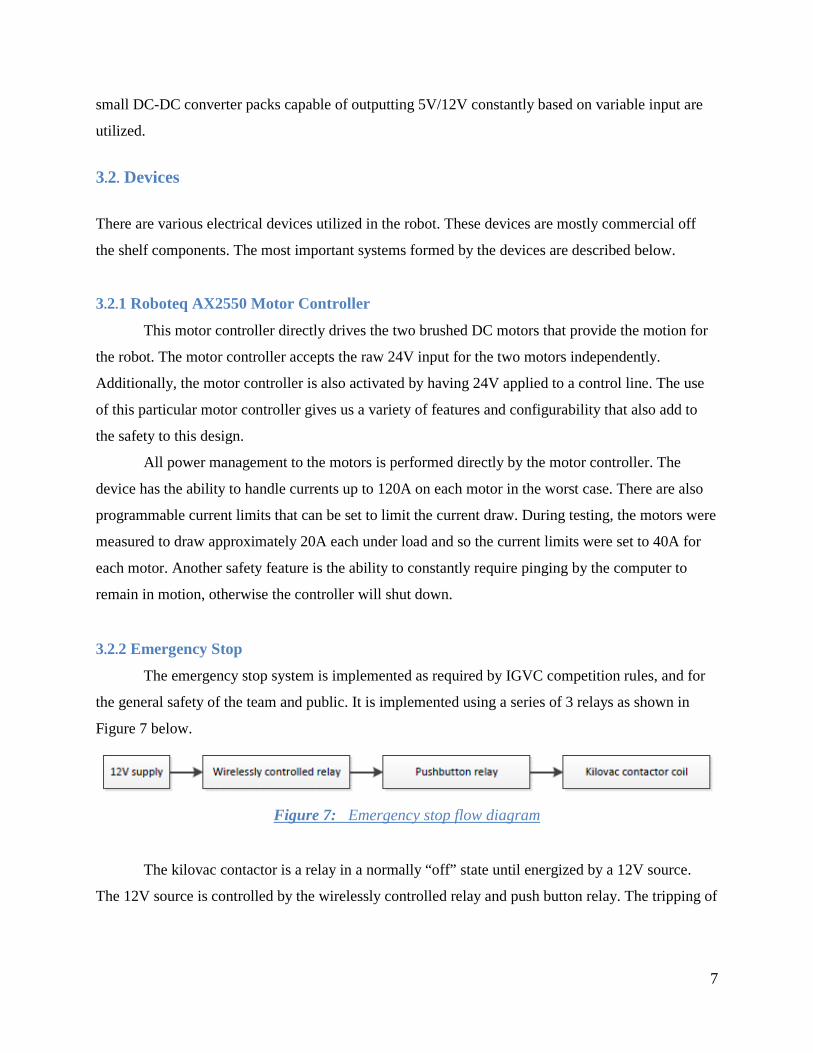
The emergency stop system is implemented as required by IGVC competition rules, and for
the general safety of the team and public. It is implemented using a series of 3 relays as shown in
Figure 7 below.
Figure 7: Emergency stop flow diagram
The kilovac contactor is a relay in a normally “off” state until energized by a 12V source.
The 12V source is controlled by the wirelessly controlled relay and push button relay. The tripping of
8
either of these relays will cutoff power to the kilovac contactor immediately. Once the contactor is
turned off, the robot will lose all power to its motors.
3.2.2.1 Wireless Relay Module
The wirelessly controlled relay is part of a device called the “Relay Function Module 2”
manufactured by Linux Technologies. It is a box that essentially contains 4 independent relays that
can be wirelessly controlled by a remote. One of the available relays is used in the emergency stop
module. The relay can be toggled between an “on” and “off” state on demand. Additionally, the relay
defaults to the “off” state.
3.2.2.2 Pushbutton Reset Module
In order to have a pushbutton to act as an emergency stop on the robot itself, a PCB was
designed and created to act as a triggerable relay circuit. It was made to be compatible with any kind
of pushbutton. The module uses no programmable elements as required by the IGVC rules and
instead utilizes basic logic ICs. One designed feature of the module is a permanent shut off of the
relay until the module has its power switched toggled off and back on. An additional feature is a 5V
logical output that indicates when the emergency stop has been tripped. This allows the onboard
computer to respond by shutting down the program.
3.2.2.3 Kilovac Contactor
The Kilovac LEV200 series contactor is the biggest relay used in the emergency stop circuit.
The motor power travels through the relay before it is fed into the motor controller. It is capable of
handling up to 500A and its switched by a 12V source.
3.2.3 On-board Computer
From previous entries in the IGVC, we found that an onboard computer system was
potentially more reliable than the previous designs using just a laptop. Two of the major issues that
the laptop had were excessive power draw and overheating during the summer. The integration of a
standard computer motherboard and components has allowed us to build a more reliable computing
system.
9
3.2.3.1 M4-ATX Power Supply
The most important component besides the motherboard is the computer power supply. This
is an off the shelf power supply meant for powering ATX standard motherboards from a DC supply
compared to the common AC supplies. It has all the connectors required for the motherboard ATX
and CPU connectors, as well as 4-pin MOLEX and SATA power connectors. The power supply is
capable of delivering up to 300W at max load and handles all power management of the connected
components, making it a perfect component to have been integrated into the design.
3.2.3.2 Motherboard
The motherboard is the most important part of any computer and the one chosen is an ATX
standard desktop motherboard. It has 8GB of memory and an Intel i5 processor. The upside in these
choices of specifications is a more powerful computing platform. The downside is the increased
power consumption by these components. However, after testing we feel the tradeoff in more power
for a reliable system is well worth it.
3.2.3.3 Solid State Drive
A Solid State Drive (SSD) is utilized due to the elimination of spinning disks utilized in hard
disk drives. An issue that exists with using conventional hard drives is that they need to be relatively
stable while writing data or else many mechanical problems may occur internally. Hard disk drives
are not ideal in environments subjected to vibrations or shock for this reason. The solid state drive is
for the most part unaffected by the movement of the robot and a logical choice.
3.2.4 Other Components of Interest
One of the main sensor systems used is the SICK LMS 210. Beyond wiring it to a power
source, very little electrical work had to be performed to get it running. Additionally, a compass
system to be decided was integrated to provide feedback on the robot’s heading. An array of fuses
was implemented for the motherboard, motors and LIDAR for a second set of short circuit and
overcurrent draw protection.
3.3. Overall Design Decisions There were a few electrical design decisions made in Project 15. They consisted of
component layout, power distribution, and components used.

10
3.3.1 Layout
The component layout on the robot is potentially suboptimal but was decided on as shown in
Figure 8. The space between related components was minimized for the ESTOP and computer
system. Additionally, the electrical junction block and switches/fuses were put as close to the power
source as possible to minimize excess wire. The side with the motor controller was left relatively
clear for unrestricted air flow to allow for cooling via forced convection because of overheating
concerns.
3.3.2 Power Distribution
The power source
created by using the two 12V
marine batteries was fed
directly to most components.
No attempt was made to
regulate the voltage fed to
the motor controller, LIDAR,
and computer power supply.
These devices all have
internal switching based
voltage regulation of some form and thus, space is saved by not requiring a large 24V regulator
component. In the cases a 5V source was required for the smaller sensor systems (compass), a small
DC/DC converter module was wired to 12V to generate the 5V.
3.3.3 Component Usage
The use of off-the-shelf components allowed for an expedited build of the robot.
Additionally, the components have more features than would be possible if for example the motor
controller was self-built. The AX2550 has a full feature programmable system capable of various
operating modes and data. Finally, a cost saving is incurred by using components without having to
waste money on prototyping and implementation.
Figure 8: Component Layout

11
4. Software
4.1 Overview The layout for this year’s robot is focused on the achievement of a fusion of all available
sensors as opposed to instinctive and reactionary methods for autonomous navigation. The software
structure of the robot is categorized based on a three tier system: Low Mid, and High Functions. This
concept was chosen as a fail-safe for ensuring the effectiveness of the robot’s navigation system.
This was needed due to the fact that as the complexity of the algorithms utilized increased during
development. In order to accomplish the concurrent usage of multiple sensors, an onboard computer
system was implemented. The embedded system consisted of one high end desktop motherboard
with a high performance quad core processor, and ample RAM. The specific system chosen was
MIL-SPEC rated for long term use, solid state components (included hard drive) and overall
durability in the most demanding of environments.
The interlinking of all onboard sensors required a modular and robust device management
system that was custom coded. Each device had event-driven connection and data management
processes which allowed for worry-free connectivity and data visibility. These new features also
provided safety checkpoints during the robot’s initialization and autonomous states. Each component
was configured so that in case of a disconnection, the robot stops any dangerous actions and displays
the state of every part of the robot platform for debugging.
4.2 Sensors
4.2.1 LIDAR
The on-board LIDAR system is the SICK LMS 221. We utilize the 0.5cm resolution with a
scan range of 180 degrees at around 20 feet away from the robot with a refresh rate of 10Hz. The
LIDAR driver was built for optimization of data handling, error handling and seamless integration
and connection with the LIDAR. A separate Comport manager was created which was designed to
ping comports and attempt to establish connections between any drivers that are registered with the
manager.
12
4.2.2 Camera
The computer vision system is comprised of two Microsoft LifeCam Cinema cameras placed
at a known distance apart on a five foot boom in the rear of the robot. The cameras faced downward
at a specific angle so that the furthermost edge of the robot is the only portion of the chassis visible in
the camera systems field of view. This placement allows for the detection of obstacles in and around
the robot with a focus on its blind spots.
4.2.3 IMU
The Inertial Measurement Unit utilized is the X-IO ARHS IMU system imported from the
UK. This device contains 3 accelerometers, 3 gyroscope and 3 compasses with an advanced Kalman
filter for near perfect noise removal. All measurement devices on the unit are at 16 bit resolution
which will give more than enough accuracy and precision in terms of measuring the forces on or by
the robot as well as the direction and geographic heading.
4.2.4 GPS
The onboard GPS system is the Raven Invicta 115 Marine GPS. It utilizes the WAAS DGPS
system with a final accuracy of about 1.4 meters with all satellites in sight. We chose this model due
to its powerful antenna, waterproof design, and ability to use the DGPS ground station system with
standard NEMA communication protocols.
4.2.5 Ultrasonic Sensor Array
An array of ultrasonic range finders with a terminal range of about 60cm was placed around
the perimeter of the robot. The devices utilized were less expensive versions of the Parallax PING)))
ultrasonic range finder and were attached to an Arduino Mega 2560 for co-processing.
4.3 Program Hierarchy
4.3.1 Low Level Functions
The LIDAR system is implemented in its simplest state and scans the area around the robot
and notes obstacles of interest based on reading size and proximity to robot. The Initial LIDAR scan
data manager categorizes obstacles by proximity into three groups, negligible, mid-range, and close
range
13
The Camera system performs its basic function and obtains images of the course in front of
the robot. The images are blurred to create a more uniform distribution of color on the floor in front
of the robot. The system then performs a Hough Transformation to detect lines on the ground. Initial
Camera Data Manager creates an array of points from the images that contain the x and y position of
each pixel detected by the Hough Transformation.
The GPS unit obtains positional data and plots a bread crumb trail of where the robot was
with the point of origin being when the robot first initiated its autonomous mode. The Initial GPS
data manager uses a Kalman filter to remove any “noise” from the GPS data to give a more accurate
reading.
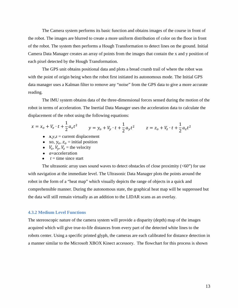
The IMU system obtains data of the three-dimensional forces sensed during the motion of the
robot in terms of acceleration. The Inertial Data Manager uses the acceleration data to calculate the
displacement of the robot using the following equations:
𝑥 = 𝑥𝑜 + 𝑉𝑥 ∙ 𝑡 +12𝑎𝑥𝑡2 𝑦 = 𝑦𝑜 + 𝑉𝑦 ∙ 𝑡 +
12𝑎𝑦𝑡2 𝑧 = 𝑧𝑜 + 𝑉𝑧 ∙ 𝑡 +
12𝑎𝑧𝑡2
● x,y,z = current displacement ● xo, 𝑦𝑜, 𝑧𝑜 = initial position ● 𝑉𝑥, 𝑉𝑦, 𝑉𝑧 = the velocity ● a=acceleration ● t = time since start
The ultrasonic array uses sound waves to detect obstacles of close proximity (<60”) for use
with navigation at the immediate level. The Ultrasonic Data Manager plots the points around the
robot in the form of a “heat map” which visually depicts the range of objects in a quick and
comprehensible manner. During the autonomous state, the graphical heat map will be suppressed but
the data will still remain virtually as an addition to the LIDAR scans as an overlay.
4.3.2 Medium Level Functions
The stereoscopic nature of the camera system will provide a disparity (depth) map of the images
acquired which will give true-to-life distances from every part of the detected white lines to the
robots center. Using a specific printed glyph, the cameras are each calibrated for distance detection in
a manner similar to the Microsoft XBOX Kinect accessory. The flowchart for this process is shown
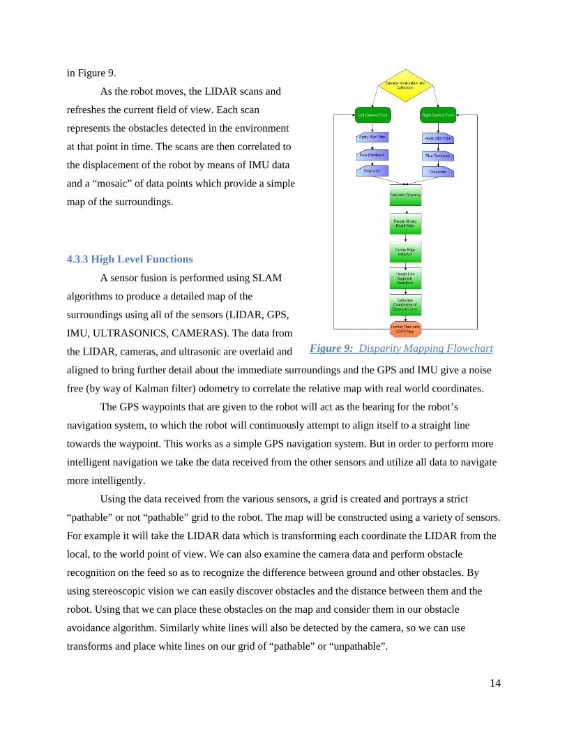
14
in Figure 9.
As the robot moves, the LIDAR scans and
refreshes the current field of view. Each scan
represents the obstacles detected in the environment
at that point in time. The scans are then correlated to
the displacement of the robot by means of IMU data
and a “mosaic” of data points which provide a simple
map of the surroundings.
4.3.3 High Level Functions
A sensor fusion is performed using SLAM
algorithms to produce a detailed map of the
surroundings using all of the sensors (LIDAR, GPS,
IMU, ULTRASONICS, CAMERAS). The data from
the LIDAR, cameras, and ultrasonic are overlaid and
aligned to bring further detail about the immediate surroundings and the GPS and IMU give a noise
free (by way of Kalman filter) odometry to correlate the relative map with real world coordinates.
The GPS waypoints that are given to the robot will act as the bearing for the robot’s
navigation system, to which the robot will continuously attempt to align itself to a straight line
towards the waypoint. This works as a simple GPS navigation system. But in order to perform more
intelligent navigation we take the data received from the other sensors and utilize all data to navigate
more intelligently.
Using the data received from the various sensors, a grid is created and portrays a strict
“pathable” or not “pathable” grid to the robot. The map will be constructed using a variety of sensors.
For example it will take the LIDAR data which is transforming each coordinate the LIDAR from the
local, to the world point of view. We can also examine the camera data and perform obstacle
recognition on the feed so as to recognize the difference between ground and other obstacles. By
using stereoscopic vision we can easily discover obstacles and the distance between them and the
robot. Using that we can place these obstacles on the map and consider them in our obstacle
avoidance algorithm. Similarly white lines will also be detected by the camera, so we can use
transforms and place white lines on our grid of “pathable” or “unpathable”.
Figure 9: Disparity Mapping Flowchart
15
From this grid the robot utilizes the A* pathfinding algorithm to estimate the shortest path
between our current location and the target location given by the GPS way point. A* works by
constructing two lists of nodes: an open list and a closed list. Nodes that have been examined are
added to the closed list while nodes that have not yet been examined are on the open list.
Initially the only node in the open list is the current node. The node with the smallest path
length is picked from the open list and then examined. Nearby walkable nodes are then added to the
open list and the process repeats. In this way we are able to construct a path which nearly represents
the shortest distance to reach the GPS point. The robot will attempt to travel along the path
constructed by the algorithm and the given grid.
In order to utilize A* algorithm in an efficient manner there are a couple of speed
improvements we can use. Rather than using a grid, we construct a Navigation Mesh which is
updated by new obstacles being registered, or obstacles being lost. The navigation mesh speeds up
performance by decreasing the number of nodes we traverse via A* as well as accommodate path
finding for a robot with some size.
As an emergency stop we will implement a function that determines if an obstacle comes
within some threshold distance. If this occurs, the robot will attempt to come to an immediate stop
and then fully evaluate the situation and then determine the next course of action. This mode will be
known as EMode, which will override most navigation functionality to attempt to remove itself from
any obstacles it’s tangled up in. After it is free, it will then resume normal navigation.
6. Conclusion P-15 was designed, built, and tested to compete in the 2012 Intelligent Ground Vehicle
Competition. Physically, our robot was designed to be robust, and yet also mobile enough to be able
to navigate around tight corners that may be present during the competition. Sensors were
implemented to take the environment and turn it into a series of digital signals that the robot could
use to find and negotiate a path through obstacles while staying within line boundaries. Through
IGVC we have gained knowledge on the challenges and awards that come from working on a
problem as complex as navigation of an autonomous vehicle.