table of contents - in.gov · 32-6.10 construction maintenance ... guidance in the hydraulic design...
TRANSCRIPT

TABLE OF CONTENTS TABLE OF CONTENTS ................................................................................................................ 1 LIST OF FIGURES ........................................................................................................................ 2
32-3A Design Storm Frequency (Bridge Waterway Openings) ............................................ 2 32-3B Design Storm Frequency for Temporary Structures ................................................... 2 32-4A Bridge Hydraulics Definitions Sketch ........................................................................ 2 32-4B Bridge Flow Types ...................................................................................................... 2 32-4C Cross Section Locations for Stream Crossing with a Single Waterway Opening ...... 2 32-4D Flow Classification According to Submergence Conditions (WSPRO User
Instructors Manual - 1990).................................................................................................. 2 32-4E Cross Section Locations in the Vicinity of Bridges .................................................... 2 32-7A Design Procedure Checklist ........................................................................................ 2
CHAPTER THIRTY-TWO ............................................................................................................ 3 32-1.0 INTRODUCTION .............................................................................................................. 3
32-1.01 Definition .................................................................................................................... 3 32-1.02 Analysis and Design ................................................................................................... 3 32-1.03 Purpose of Chapter ..................................................................................................... 3
32-2.0 POLICY .............................................................................................................................. 4 32-2.01 General Policy ............................................................................................................ 4 32-2.02 General INDOT Policy ............................................................................................... 4 32-2.03 INDOT Bridge-Sizing Policy ..................................................................................... 5
32-3.0 DESIGN CRITERIA .......................................................................................................... 6 32-3.01 General Criteria .......................................................................................................... 6 32-3.02 INDOT Criteria........................................................................................................... 7
32-3.02(01) Roadway Serviceability ................................................................................. 7 32-3.02(02) Design Flood .................................................................................................. 8 32-3.02(03) Freeboard ....................................................................................................... 8 32-3.02(04) Span Lengths .................................................................................................. 8 32-3.02(05) Flow Distribution ........................................................................................... 8 32-3.02(06) Scour .............................................................................................................. 8 32-3.02(07) Temporary-Runaround Structure ................................................................... 9 32-3.02(08) Channel Clearing ........................................................................................... 9
32-4.0 DESIGN PROCEDURE ..................................................................................................... 9 32-4.01 Survey Accuracy (Computation Method)................................................................... 9 32-4.02 Design-Procedure Outline ........................................................................................ 10 32-4.03 Hydraulic Performance of Bridge............................................................................. 13 32-4.04 Methodologies .......................................................................................................... 14
32-4.04(01) Momentum ................................................................................................... 14 32-4.04(02) HEC-RAS .................................................................................................... 14 32-4.04(03) Energy (HDS-1) ........................................................................................... 15 32-4.04(04) Energy (WSPRO)......................................................................................... 15 32-4.04(05) Two-Dimensional Modeling ........................................................................ 15
32-4.05 WSPRO Modeling .................................................................................................... 17 32-4.06 HEC-2 Modeling ...................................................................................................... 17
32-5.0 BRIDGE SCOUR OR AGGRADATION ........................................................................ 19 32-5.01 Introduction .............................................................................................................. 19 32-5.02 Scour Types .............................................................................................................. 20
32-5.02(01) Long-Term Profile Changes ........................................................................ 20
2012

32-5.02(02) Plan-Form Change ....................................................................................... 21 32-5.02(03) Contraction ................................................................................................... 21 32-5.02(04) Local Scour .................................................................................................. 21
32-5.03 Armoring .................................................................................................................. 22 32-5.04 Scour Resistant Materials ......................................................................................... 22 32-5.05 Scour-Analysis Methods........................................................................................... 22 32-5.06 Scour-Assessment Procedure ................................................................................... 23
32-5.06(01) Site Data ....................................................................................................... 23 32-5.06(02) General ......................................................................................................... 24
32-5.07 Pressure-Flow Scour ................................................................................................. 25 32-6.0 DESIGN PHILOSOPHY .................................................................................................. 26
32-6.01 Introduction .............................................................................................................. 26 32-6.02 Location of Stream Crossing .................................................................................... 26 32-6.03 Coordination, Permits, and Approvals ..................................................................... 27 32-6.04 Environmental Considerations ................................................................................. 27 32-6.05 Stream Morphology .................................................................................................. 27 32-6.06 Data Collection ......................................................................................................... 28 32-6.07 Scour ......................................................................................................................... 28 32-6.08 Preventive or Protection Measures ........................................................................... 29 32-6.09 Deck Drainage .......................................................................................................... 30 32-6.10 Construction Maintenance ........................................................................................ 30 32-6.11 Waterway Enlargement ............................................................................................ 31 32-6.12 Auxiliary Openings................................................................................................... 31
32-7.0 DESIGN PROCEDURE FORM ...................................................................................... 32 32-8.0 REFERENCES ................................................................................................................. 32
LIST OF FIGURES Figure Title 32-3A Design Storm Frequency (Bridge Waterway Openings) 32-3B Design Storm Frequency for Temporary Structures 32-4A Bridge Hydraulics Definitions Sketch 32-4B Bridge Flow Types 32-4C Cross Section Locations for Stream Crossing with a Single Waterway Opening 32-4D Flow Classification According to Submergence Conditions (WSPRO User Instructors Manual - 1990) 32-4E Cross Section Locations in the Vicinity of Bridges 32-7A Design Procedure Checklist
2012

CHAPTER THIRTY-TWO
BRIDGE HYDRAULICS 32-1.0 INTRODUCTION 32-1.01 Definition A bridge is defined as follows: 1. a structure that transports traffic over a waterway, railroad, road or other obstruction; 2. a part of a stream-crossing system that includes the approach roadway over the
floodplain, relief openings, and the bridge structure; and 3. legally, a structure with a total span of 20 ft or longer, measured along the centerline of
the roadway. For a multiple-pipe structure, this includes the distance between the pipes. However, a structure designed hydraulically as a bridge as described above is treated in this Chapter, regardless of length.
See Figure 31-1A, Maximum Span Length for Culvert, for precise definitions on the measurement of span length to distinguish between a bridge and a culvert. 32-1.02 Analysis and Design Proper hydraulic analysis and design is as vital as the structural design. A stream-crossing system should be designed for the following: 1. minimum cost subject to applicable criteria; 2. desired level of hydraulic performance up to an acceptable risk level; 3. mitigation of impacts on stream environment; and 4. accomplishment of social, economic, and environmental goals. 32-1.03 Purpose of Chapter This Chapter includes the following: 1. guidance in the hydraulic design of a stream-crossing system through the following:
2012

a. appropriate policy and design criteria; and b. technical aspects of hydraulic design;
2. non-hydraulic factors that influence design including the following:
a. environmental concerns; b. emergency access, traffic service; and c. consequences of catastrophic loss;
3. a design procedure which emphasizes hydraulic analysis using the computer programs
WSPRO and HEC-2; and 4. a brief section on design philosophy. A more in-depth discussion is provided in the
AASHTO Highway Drainage Guidelines, Chapter VII. 32-2.0 POLICY 32-2.01 General Policy Policy is a set of goals or a plan of action. Federal and State policies that broadly apply to drainage design are provided in Chapter Twenty-eight. Policies that are unique to bridge crossings are provided herein. The hydraulic analysis should consider a number of stream-crossing system designs to determine the most cost-effective proposal consistent with design constraints. 32-2.02 General INDOT Policy The following general INDOT policy identifies specific areas for which quantifiable criteria can be developed. 1. The final design selection should consider the maximum backwater allowed by IDNR or
INDOT. See Chapter Twenty-nine. 2. The final design should not significantly alter the flow distribution in the floodplain. 3. The crest-vertical curve profile should be considered as the preferred highway crossing
profile in allowing for embankment overtopping at a lower discharge.
2012

4. A 2-ft freeboard should be established to allow for passage of ice and debris. For a navigation channel, a vertical clearance in accordance with Federal or IDNR requirements should be established based on expected flows during the navigation season.
5. Degradation or aggradation of the river and contraction or local scour should be
estimated. Appropriate positioning of the foundation, below the total scour depth if practical, should be included as part of the final design.
32-2.03 INDOT Bridge-Sizing Policy The INDOT bridge-sizing policy is as follows. 1. Category 1. A bridge that does not require an Indiana Department of Natural Resources
(IDNR) Permit. 2. Category 2. A bridge that does require an IDNR Permit. A structure that requires an IDNR Permit (Certificate of Approval for Construction in a Floodway) includes the following: 1. structure with a drainage area greater than 50 mi2 in a rural area; or 2. structure with a drainage area greater than 1 mi2 in an urban area. A rural area is defined in the Indiana Register, Volume 16, Number 6, March 1, 1993, p. 1527, as follows:
An area where the flood protection grade of each residential, commercial, or industrial building impacted by this project is higher than the regulatory flood elevation under the project control, and where the area lies outside:
(i) the corporate boundaries of the consolidated city or an incorporated city
or town; and
(ii) the territorial authority for comprehensive planning established under IC 36-7-4-205(b).
An area cannot be rural if it lies within a city or its planning zone, or if a finished floor elevation within the project backwater limits is below the Q100 elevation.
2012

A project with a drainage area less than that listed above will not require a permit from IDNR. See Chapter Nine for more information on the IDNR Construction in a Floodway Permit. For a new bridge on a new alignment, the maximum backwater should not exceed 1.5 in. The 1.5-in maximum may be modified as follows: 1. the backwater dissipates to 1.5 in or less at the right-of-way line; 2. the channel is sufficiently deep to contain the increased elevation without overtopping the
banks; or 3. a flood easement may be purchased upstream of the bridge to allow for greater than 1.5
in. of backwater. The cost savings should be enough to offset the cost of the flood easement and the possible delay in constructing the project. Past experience has shown that this option may delay a project by one or more years.
The Hydraulics Engineer must approve an exception to the 1.5-in. backwater allowance for a new bridge on a new alignment. For existing or baseline conditions, the IDNR limits surcharge to 1.25 in., urban or rural area. Existing conditions are defined as the water-surface profile that results from only those encroachments that have been in place since 1973. Although IDNR policy will allow for a slight increase over existing conditions, INDOT will not. INDOT policy for a bridge replacement or bridge rehabilitation is that the surcharge created by a proposed structure must be equal to or less than the existing surcharge, unless the existing surcharge is less than 1.25 in. This will allow future widening of the structure. If the surcharge created by an existing structure is greater than 12 in., the proposed surcharge for the bridge replacement or bridge rehabilitation project must not be greater than 12 in. above the natural channel flood profile. FHWA does not require economic justification for a bridge that causes less than 12 in. of backwater. Therefore, a formal risk assessment will not be required. 32-3.0 DESIGN CRITERIA Design criteria are the tangible means for placing accepted policies into action, and become the basis for the selection of the final design configuration of the stream-crossing system. Criteria are subject to change if conditions so dictate, or as approved by the Hydraulics Engineer. 32-3.01 General Criteria
2012

The following are the AASHTO general criteria related to the hydraulic analysis for the location and design of a bridge, as stated in the Highway Drainage Guidelines. 1. Backwater will not significantly increase flood damage to property upstream of the
crossing. 2. Velocity through the structure will not damage the highway facility nor increase damage
to adjacent property. 3. Maintain the existing flow distribution as practical. 4. Provide pier spacing and orientation and abutments designed to minimize flow disruption
and potential scour. 5. Provide foundation design or scour countermeasures to avoid failure due to scour. 6. Design pier spacing and freeboard at the structure to pass anticipated debris and ice. 7. Consider acceptable risks of damage or viable measures to counter the vagaries of an
alluvial stream. 8. Consider minimal disruption of ecosystems and values unique to the floodplain and
stream. 9. Provide a level of traffic service compatible with that expected for the class of highway
and compatible with the projected traffic volume. 10. Design choices should support costs for construction, maintenance, and operation,
including probable repair and reconstruction and potential liability that are affordable. 32-3.02 INDOT Criteria The criteria described below and Figure 32-3A, Design-Storm Frequency, Bridge Waterway Opening, augment the general criteria described in Section 32-3.01. They provide specific, quantifiable values that relate to local site conditions. Evaluation of alternatives according to these criteria can be accomplished by using the water-surface profile programs WSPRO or HEC-2. 32-3.02(01) Roadway Serviceability
2012

See Section 31-3.04(02). 32-3.02(02) Design Flood A structure and its approach roadways should be designed, at a minimum, for the passage of the design-year flood specified for the required road serviceability for the highway classification system specified. By definition, a design flood will not overtop the roadway. As shown in Chapter Twenty-nine and Figure 32-3A, Design-Storm Frequency, Bridge Waterway Opening, the backwater must be calculated from the Q100 flood which may exceed the design flood. 32-3.02(03) Freeboard Where practical, a minimum clearance of 2 ft should be provided between the design approach water-surface elevation and the low chord of the bridge for the final design alternative to allow for passage of ice and debris. Where this is not practical, the clearance should be established by the designer based on the type of stream and level of protection desired as approved by INDOT. For example, 1 ft should be adequate for a small stream that normally does not transport drift. An urban bridge with a grade limitation may provide no freeboard. A 3 ft freeboard is desirable for a major river which is known to carry large debris. The crest vertical curve profile is the preferred highway crossing profile in allowing for embankment overtopping at a lower discharge. 32-3.02(04) Span Lengths The minimum span length for a bridge with more than 3 spans should be 100 ft for those spans over the main channel. A three-span bridge should have the center span length maximized at a site where debris may be a problem. For a two-span bridge, span lengths are subject to approval by the Hydraulics Engineer. 32-3.02(05) Flow Distribution The conveyance of the proposed stream-crossing location should be calculated to determine the flow distribution and to establish the location of a bridge opening. The proposed facility should not cause a significant change in the existing flow distribution. 32-3.02(06) Scour
2012

Design for bridge foundation scour considering the magnitude of flood, including the 100-year (1%) event, which generates the maximum scour depth. The design should use a geotechnical design practice safety factor of 2 to 3. The resulting design should then be checked using a super flood, Q500. Use 1.7 times the magnitude of the 100-year (1%) event if no other source for Q500 is available and a geotechnical design practice safety factor of at least 1.0. See Section 32-6.08. 32-3.02(07) Temporary-Runaround Structure A temporary-runaround structure is operational for three months to two years. Therefore, the serviceability criteria are greatly reduced. At a minimum, a temporary runaround should be serviceable during a Q2 discharge, and should be checked for allowable backwater at a Q100 discharge. The best way to achieve this objective is to set the grade of the temporary runaround as close as possible to the elevations corresponding with the serviceability levels shown in Figure 32-3B, Design-Storm Frequency for Temporary Structure. Backwater must be computed for the design storm and Q100 discharges. For a structure requiring an IDNR permit, the backwater at Q100 must not exceed 1.5 in. over the base condition (i.e., existing backwater elevation). Base condition is the condition of the floodplain on January 1, 1973, but without an unauthorized dam or levee. If an activity after December 31, 1972, lowered the regulatory-flood profile, the floodplain under the lower profile is the base condition. For a structure not requiring an IDNR permit, the backwater from the Q100 event should not exceed the finished-floor elevations of nearby buildings or residences. 32-3.02(08) Channel Clearing Channel clearing consists of the removal of sediment to enlarge the waterway opening. Channel clearing should not occur below 1 ft above the Ordinary High Water elevation. For an intermittent stream, where the Ordinary High Water elevation is very near the flowline elevation, channel clearing should not occur below 2 ft above the flowline elevation. 32-4.0 DESIGN PROCEDURE 32-4.01 Survey Accuracy (Computation Method) The design for a stream-crossing system requires a comprehensive engineering approach that includes formulation of alternatives, data collection, selection of the most cost-effective alternative according to established criteria, and documentation of the final design. Water-surface profiles are computed for technical uses including the following:
2012

1. flood insurance study; 2. flood hazard mitigation investigation; 3. drainage crossing analysis; and 4. longitudinal encroachment. The completed profile can affect the highway bridge design and is the mechanism for determining the effect of a bridge opening on upstream water levels. Errors associated with computing water-surface profiles with the step-backwater profile method can be classified as follows: 1. data estimation errors resulting from incomplete or inaccurate data collection and
inaccurate data estimation; 2. errors in accuracy of energy-loss calculations depending on the validity of the energy-loss
equation employed and the accuracy of the energy-loss coefficients (Manning’s n value is the coefficient measuring boundary friction);
3. inadequate length of stream reach investigated; and 4. significant computational errors resulting from using cross-sectional spacings which are
incorrectly considered to be adequate. The errors are due to inaccurate integration of the energy-loss-distance relationship which is the basis for profile computations. These errors may be reduced by adding interpolated or actual sections (more calculation steps).
32-4.02 Design-Procedure Outline The following design-procedure outline should be used. Although the scope of the project and individual site characteristics make each design unique, this procedure should be applied unless indicated otherwise by INDOT. 1. Data Collection.
a. Survey (1) Topography (2) Geology (3) High-water marks (4) History of debris accumulation, ice, and scour (5) Maps and aerial photographs (6) Field reconnaissance
2012
b. Influences on Hydraulic Performance of Site (1) Other streams, reservoirs, water intakes (2) Structures upstream or downstream (3) Natural features of stream and floodplain (4) Channel modifications upstream or downstream (5) Floodplain encroachments (6) Sediment types and bed forms (Also see FHWA HEC 20, Appendix C,
Scour, Site Data, Level I Qualitative Analysis, 1991)
c. Environmental Impact (1) Existing bed or bank instability (Level I) (2) Floodplain land use and flow distribution (3) Environmentally-sensitive areas (fisheries, wetlands, etc.) (4) Level I Qualitative Analysis (FHWA HEC 20, 1991)
c. Site-Specific Design Criteria
(1) Road serviceability (design frequency) (2) Flood damage potential (3) Freeboard
2. Hydrologic Analysis.
a. Studies by Other Agencies (1) Federal Flood Insurance Studies (2) Federal Floodplain Studies by the COE, NRCS, etc. (3) IDNR and Local Floodplain Studies (4) Hydraulic performance of existing bridge
b. Watershed Morphology (1) Drainage area (attach map) (2) Watershed and stream slope (3) Channel geometry
c. Hydrologic Computations (1) Discharge and frequency for historical flood that complements the high-
water marks used for calibration (2) Discharges for specified frequencies
3. Hydraulic Analysis.
a. Computer Model Calibration and Verification b. Hydraulic Performance for Existing Conditions c. Hydraulic Performance of Proposed Designs d. Scour Computations
2012
4. Selection of Final Design.
a. Measure of compliance with established hydraulic criteria b. Compare proposed bridge size and backwater to the existing bridge c. Consider environmental and social criteria d. Make final selection e. Design of riprap, scour abatement, river training, etc.
5. Documentation. A bridge-waterway study is required at the Hydraulics Grade Review
plan submittal. The study requires the following.
a. Drainage-Area Determination. The drainage area can be obtained by planimeter from USGS Quad Maps using the USGS manual Drainage Areas of Indiana Streams for supplemental data as needed. For a large stream, the drainage area can be obtained from the USGS Manual Drainage Areas of Indiana Streams. The sources used must be photocopied and attached to the bridge waterway study.
b. Hydrologic Analysis. Complete documentation of the method used and all
relevant variables. See Chapter Twenty-nine for allowable methods.
c. Hydraulic Analysis of Existing and Proposed Conditions. See Section 32-4.04. A hardcopy of all input and output files and a site plan that illustrates the location of all cross sections used in the hydraulic analysis is required. A disk with all input files must also be submitted.
d. Justification of Selected Bridge. A summary of the results of the hydraulic
analysis of bridge types is required.
e. Summary of Hydraulic Parameters. Summarize the bridge-waterway study by listing the parameters as follows:
(1) drainage area; (2) Q100 discharge; (3) Q100 elevation; (4) backwater; (5) velocity; (6) waterway area; (7) low-structure elevation; (8) skew; (9) existing waterway opening; (10) existing low-structure elevation; and
2012

(11) existing backwater.
f. Files. Provide one diskette containing all input and output files for WSPRO or HEC-2.
g. Layout Sheet for LPA Project. This must show the following:
(1) profile grade (existing and proposed); (2) waterway opening; (3) pier placement; (4) superstructure; (5) hydraulic data; and (6) Q100 elevation;
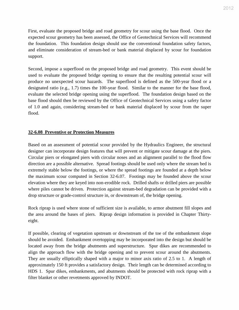
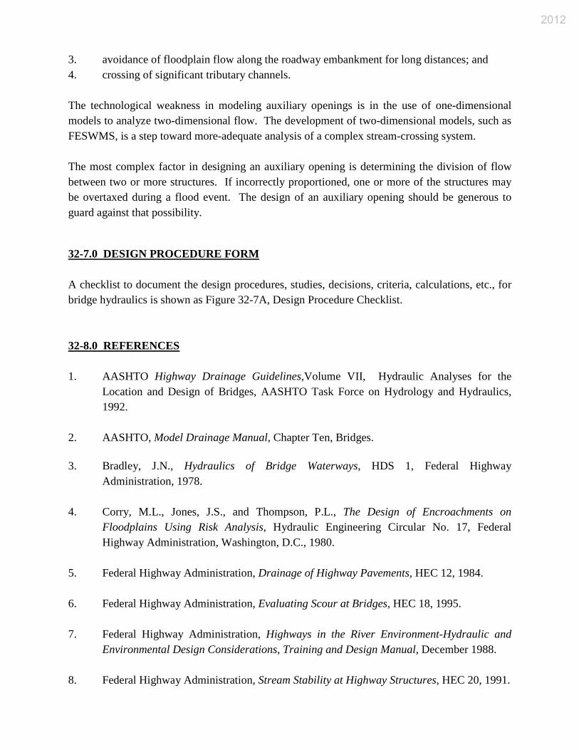
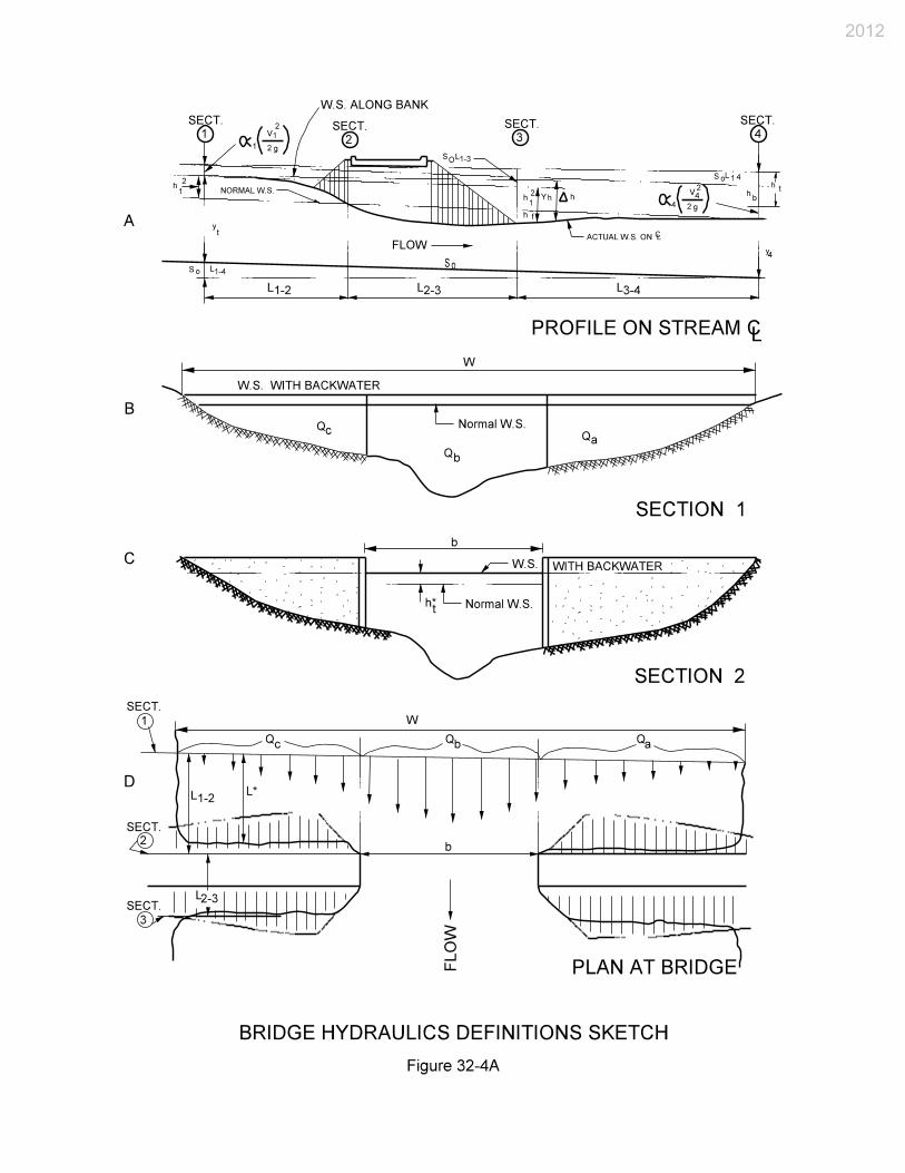
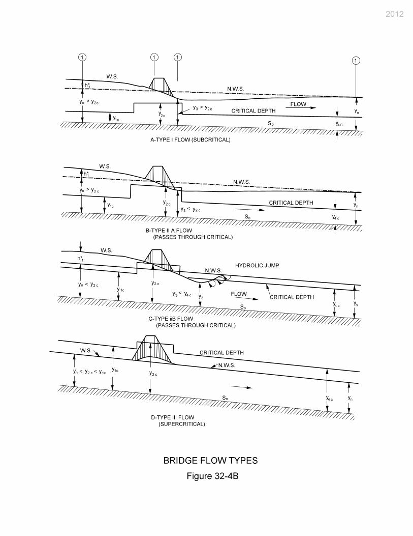
If road overflow is expected, the Plan and Profile sheet must show the limits of road overflow. A checklist form is provided in Section 32-7.0. 32-4.03 Hydraulic Performance of Bridge The stream-crossing system is subject to either free-surface flow or pressure flow through one or more bridge openings with possible embankment overtopping. These hydraulic complexities should be analyzed using WSPRO or HEC-2 unless indicated otherwise by INDOT. Alternative methods of analysis of bridge hydraulics are discussed below, but emphasis is placed on the use of WSPRO. It is impractical to perform the hydraulic analysis for a bridge by manual calculations due to the interactive and complex nature of those computations. However, an example of the basic manual calculations is included in the AASHTO Model Drainage Manual, Chapter 10, Appendix D, as an explanation of the aspects of bridge hydraulics. The hydraulic variables and flow types are defined in Figure 32-4A, Bridge-Hydraulics Definitions Sketch, and Figure 32-4B, Bridge Flow Types. The following applies. 1. Backwater, h1, is measured relative to the normal water-surface elevation without the
effect of the bridge at the approach cross section (Section 1). It is the result of contraction and re-expansion head losses and head losses due to bridge piers. Backwater can also be the result of a “choking” condition in which critical depth is forced to occur in the contracted opening with a resultant increase in depth and specific energy upstream of the contraction. This is illustrated in Figure 32-4B.
2012

2. Type I flow consists of subcritical flow throughout the approach, bridge, and exit cross sections, and is the most common condition encountered in practice.
3. Type IIA and IIB flows both represent subcritical approach flows which have been
choked by the contraction, resulting in the occurrence of critical depth in the bridge opening. In Type IIA, the critical water-surface elevation in the bridge opening is lower than the undisturbed normal water-surface elevation. In Type IIB, it is higher than the normal water surface elevation. A weak hydraulic jump immediately downstream of the bridge contraction is possible.
4. Type III flow is supercritical approach flow and remains supercritical through the bridge
contraction. Such a flow condition is not subject to backwater unless it chokes and forces the occurrence of a hydraulic jump upstream of the contraction.
32-4.04 Methodologies No single method is ideally suited for every situation. If a satisfactory computation cannot be achieved with a given method, an alternative method should be attempted. However, it has been found that, with attention to the setup requirements of each method, essentially duplicative results can usually be achieved using both momentum and energy methods. 32-4.04(01) Momentum The Corps of Engineers’ HEC-2 model uses a variation of the momentum method in the bridge routine where there are bridge piers. The momentum equation between cross sections 1 and 3 is used to detect Type II flow and solve for the upstream depth with critical depth in the bridge contraction. This model has been used for the majority of the flood-insurance studies performed under the NFIP. However, some believe that the bridge-analysis routines in HDS-1 and WSPRO may yield a better definition of actual hydraulic performance. 32-4.04(02) HEC-RAS The Corps of Engineers’ Hydrologic Engineering Center (HEC) has developed the HEC-RAS (River Analysis System) program package. It operates under WINDOWS and has full graphic support. The package includes all the features inherent to HEC-2 and WSPRO, plus program selected friction slope methods, mixed flow regime capability, automatic n value calibration, ice
2012
cover, quasi 2-D velocity distribution, superelevation around bends, bank erosion, riprap design, stable channel design, sediment transport calculations, and scour. HEC-RAS Version 2.2 will provide the outputs necessary to evaluate bridge hydraulics for all flow types. However, earlier versions will not be accepted for bridge hydraulics computations. 32-4.04(03) Energy (HDS-1) The method developed by FHWA described in HDS-1 is an energy approach with the energy equation written between cross sections 1 and 4 as shown in Figure 32-4B, Bridge Flow Types, for Type I flow. The backwater is defined as the increase in the approach water-surface elevation relative to the normal water-surface elevation without the bridge. This model utilizes a single typical cross section to represent the stream reach from points 1 to 4 on Figure 32-4B. It also requires the use of a single energy gradient. This method is no longer allowed by INDOT for final design analysis of a bridge due to its inherent limitations, but it may be useful for preliminary analysis and training. Studies performed by the Corps of Engineers for the FHWA show the need to utilize a multiple cross-section method of analysis to achieve reasonable stage-discharge relationships at a bridge. 32-4.04(04) Energy (WSPRO) WSPRO combines step-backwater analysis with bridge backwater calculations. This method allows for pressure flow through the bridge, embankment overtopping, and flow through multiple openings and culverts. It also includes an improved technique for determining approach flow lengths and the introduction of an expansion loss coefficient. The flow-length improvement was found necessary where approach flows occur on a very wide, heavily vegetated floodplain. The program also greatly facilitates the hydraulic analysis required to determine the least-cost alternative. WSPRO is suggested for both preliminary and final analyses of bridge hydraulics. If only a single surveyed cross section is available, the input-data propagation features of WSPRO make it easy to apply with more comprehensive output available than with HDS-1. 32-4.04(05) Two-Dimensional Modeling The water-surface profile and velocities in a section of river are often predicted using a computer model. In practice, most analysis is performed using one-dimensional methods such as the standard step method found in WSPRO or HEC-2. Although one-dimensional methods are
2012

adequate for many applications, these methods cannot provide a detailed determination of the cross-stream water surface elevations, flow velocities, or flow distribution. Two-dimensional models are more complex and require more time to set up and calibrate. They require essentially the same field data as a one-dimensional model and, depending on complexity, may require a little more computer time. Bri-Stars is a semi-two-dimensional model capable of computing alluvial scour or deposition through subcritical, supercritical, and a combination of both flow conditions involving hydraulic jumps. It is capable of simulating channel widening or narrowing and local scour due to highway encroachments. It has a bridge component which allows the computation of hydraulic flow variables and the resulting scour. Bri-Stars also includes a companion expert system program which allows classifying a stream by its morphological properties. See Section 30-5.0 for a more complete discussion of Bri-Stars. The USGS has developed a two-dimensional finite element model for the FHWA that is designated FESWMS. This model has been developed to analyze flow at a bridge crossing where complicated hydraulic conditions exist. This two-dimensional modeling system is flexible and may be applied to many types of steady and unsteady flow problems, including multiple-opening bridge crossing, spur dike, floodplain encroachment, multiple channels, flow around an island, and flow in an estuary. Where the flow is essentially two-dimensional in the horizontal plane, a one-dimensional analysis may lead to costly over-design or possibly improper design of hydraulic structures and improvements. 32-4.04(06) Physical Modeling A complex hydrodynamic situation defies accurate or practical mathematical modeling. Physical models should be considered as follows: 1. hydraulic performance data are needed that cannot be reliably obtained from
mathematical modeling; 2. risk of failure or excessive over-design is unacceptable; and 3. research is needed. The constraints on physical modeling are as follows: 1. size (scale);
2012
2. cost; and 3. time. 32-4.05 WSPRO Modeling In theory, the water-surface profile used in the hydraulic analysis of a bridge should extend from a point downstream of the bridge that is beyond the influence of the constriction, to a point upstream that is beyond the extent of the bridge backwater. In practice, all of the cross sections that are actually necessary for the energy analysis through the bridge opening for a single-opening bridge without spur dikes are shown in Figure 32-4C, Cross-Section Locations for Stream Crossing with a Single Waterway Opening. The additional cross sections that are necessary for computing the entire profile are not shown in this Figure. Cross sections 1, 3, and 4 are required for a Type I flow analysis and are referred to as the approach section, bridge section, and exit section, respectively. Cross section 3F, which is identified as the full-valley section, is needed for the water-surface profile computation without the presence of the bridge contraction. Cross section 2 is used as a control point in Type II flow but requires no input data. Two more cross sections must be defined if spur dikes and a roadway profile are specified. Pressure flow through the bridge opening is assumed to occur where the depth just upstream of the bridge opening exceeds 1.1 times the hydraulic depth of the opening. The flow is then calculated as orifice flow with the discharge proportional to the square root of the effective head. Submerged orifice flow is treated similarly with the head redefined. WSPRO can also simultaneously consider embankment overflow as a weir discharge. This leads to flow classes 1 through 6 as shown in Figure 32-4D, Flow Classification According to Submergence Conditions (WSPRO User Instructors Manual - 1990). In free-surface flow, there is no contact between the water surface and the low-girder elevation of the bridge. In orifice flow, only the upstream girder is submerged. In submerged-orifice flow, both the upstream and downstream girders are submerged. A total of four different bridge types can be analyzed. The user’s instruction manual for WSPRO should serve as a source for more-detailed information on using the computer model. Some specific example problems are provided in Model Drainage Manual, Chapter 10, Appendix B, with sample computer input and output data provided. Only the information required to understand the examples is included. 32-4.06 HEC-2 Modeling In theory, the water surface profile used in the hydraulic analysis of a bridge should extend from a point downstream of the bridge that is beyond the influence of the constriction, to a point
2012

upstream that is beyond the extent of the bridge backwater. The cross sections that are necessary in practice for the analysis of a single-opening bridge using the special bridge option are shown in Figure 32-4E, Cross Section Locations in the Vicinity of a Bridge. Energy losses caused by a structure such as a bridge or culvert are computed in two parts. First, the losses due to expansion and contraction of the cross section on the upstream and downstream sides of the structure are computed in the standard step calculations. Secondly, the loss through the structure itself is computed by either the normal-bridge or the special-bridge method. The user’s instructional manual for HEC-2 should serve as a source for more-detailed information for using the computer model. Input/output examples are provided. HEC-2 has its own data creation package, COED, that assists the user with preparing and editing input data and includes online help features. A separate, stand-alone data-editing program which checks for input/modeling errors is also provided. Cross-section, water-surface profile, and rating-curve viewing/plotting/printing are provided using the PLOT2 program. The normal-bridge method handles the cross section at the bridge just as it can at a river cross section with the exception that the area of the bridge below the water surface is subtracted from the total area. The wetted perimeter is increased where the water-surface elevation exceeds the low chord. The normal-bridge method is particularly applicable for a bridge without piers, a bridge under high submergence, or for low flow through a circular or arch culvert. Where flow crosses critical depth in a structure, the special-bridge method should be used. The normal-bridge method is automatically used by the computer, though data were prepared for the special-bridge method, for a bridge without piers and under low-flow control. The special-bridge method can always be used, but it should be used for a bridge with piers where low flow or pressure flow controls, or where flow passes through critical depth in passing through the structure. The special-bridge method computes losses through the structure for low flow, weir flow, and pressure flow, or for a combination of these. A series of program capabilities are available to restrict flow to the effective flow areas of cross sections. Among these capabilities are options to simulate sediment deposition, to confine flow to a levied channel, to block out roadway fill or a bridge deck, and to analyze floodplain encroachments. Cross sections with low overbank areas or levees require consideration in computing water-surface profiles because of possible overflow into areas outside the main channel. The computations are based on the assumption that all of the area below the water-surface elevation is effective in passing the discharge. However, if the water-surface elevation at a particular cross section is less than the top-of-levee elevation, and if the water cannot enter or leave the overbanks upstream of that cross section, the flow areas in these overbanks should not be used in the computations. Variable IEARA on the X3 card and the bank stations coded on the X1 card
2012

in fields 3 and 4 are used for this condition. By setting IEARA equal to 10, the program will consider only flow confined by the levees, unless the water-surface elevation is above the top of one or both levees, such that flow areas outside the levees will be included. If this option is used and the water-surface elevation is close to the top of a levee, it may not be possible to balance the assumed and computed water surface elevations due to the changing flow areas just above and below the levee top. Where this condition occurs, a statement will be printed that states that the assumed and computed water-surface elevations for the cross section cannot be balanced. A water-surface elevation equal to the elevation which came closest to balancing will be adopted. The program user should determine the appropriateness of the assumed water-surface elevation and restart the computation at that cross section if required. The user should study the flow pattern of the river where levees exist. If, for example, a levee is open at both ends and flow passes behind the levee without overtopping it, IEARA equals 0, or a blank should be input. Also, assumptions regarding effective-flow areas may change with changes in flow magnitude. Where cross-section elevations outside the levee are considerably lower than the channel bottom, it may be necessary to set IEARA equal to 10 to confine the flow to the channel. A user’s instruction manual for HEC-2 is available and should serve as a source for more-detailed information on using this computer model. 32-5.0 BRIDGE SCOUR OR AGGRADATION 32-5.01 Introduction Hydraulic analysis of a bridge design requires that an assessment be made of the proposed bridge’s vulnerability to undermining due to potential scour. Because of the extreme hazard and economic hardships posed by a rapid bridge collapse, considerations must be made in selecting appropriate flood magnitudes for use in the analysis. The hydraulics engineer must endeavor to always be aware of and use the most current scour-forecasting technology. The FHWA has issued Technical Advisory TA 5140.20 on bridge scour. The document, Interim Procedures for Evaluating Scour at Bridges is an attachment to the Technical Advisory. The interim procedures were replaced by HEC 18 (1991, 1993, 1995). Users of this Manual should see HEC 18 for a more thorough treatise on scour and scour prediction methodology. A companion FHWA document to HEC 18 is HEC 20, Stream Stability at Highway Structures. The inherent complexities of stream stability, further complicated by highway-stream crossings, require a multilevel solution procedure. The evaluation and design of a highway-stream crossing or encroachment should begin with a qualitative assessment of stream stability. This involves application of geomorphic concepts to identify potential problems and alternative solutions. This
2012

analysis should be followed with quantitative analyses using basic hydrologic, hydraulic, and sediment-transport engineering concepts. Such analyses can include evaluation of flood history, channel hydraulic conditions (including, for example, water-surface profile analysis), and basic sediment transport analyses such as evaluation of watershed sediment yield, incipient motion analysis, and scour calculations. This analysis can be considered adequate if the problems are resolved and the relationships between different factors affecting stability are adequately explained. If not, a more complex quantitative analysis based on detailed mathematical modeling or physical hydraulic models should be considered. This multilevel approach is provided in HEC 20. Less hazardous are problems associated with aggradation. Where freeboard is limited, problems associated with increased flood hazards to upstream property or to the traveling public due to more frequent overtopping may occur. Where aggradation is expected, it may be necessary to evaluate these consequences. Aggradation in a stream reach may serve to moderate potential scour depths. Aggradation can be referred to as negative scour. 32-5.02 Scour Types Present technology dictates that bridge scour should be evaluated as the interrelated components as follows: 1. long-term profile changes (aggradation or degradation); 2. plan form change (lateral channel movement); 3. contraction scour or deposition; and 4. local scour. 32-5.02(01) Long-Term Profile Changes Long-term profile changes can result from stream-bed profile changes that occur from aggradation or degradation. 1. Aggradation is the deposition of bed load due to a decrease in the energy gradient. 2. Degradation is the scouring of bed material due to increased stream sediment transport
capacity which results from an increase in the energy gradient. Forms of degradation and aggradation should be considered as imposing a permanent future change for the stream-bed elevation at a bridge site if they can be identified.
2012

32-5.02(02) Plan-Form Change A plan-form change is a morphological change such as meander migration or bank widening. The lateral movement of a meander can threaten bridge approaches and increase scour by changing flow patterns approaching a bridge opening. Bank widening can cause significant changes in the flow distribution and thus the bridge’s flow-contraction ratio. 32-5.02(03) Contraction Channel contraction scour results from a constriction of the channel which may, in part, be caused by bridge piers in the waterway. Deposition results from an expansion of the channel or from the bridge site being positioned immediately downstream of a steeper reach of stream. A highway, bridge, or natural-channel contraction is the most commonly encountered cause of contraction scour. The practices provided herein for estimating deposition or contraction scour are as follows. 1. Sediment Routing Practice. This practice should be considered if either bed armoring or
aggradation from an expanding reach is expected to cause an unacceptable hazard. 2. Empirical Practice. This practice is adapted from laboratory investigations of bridge
contractions in non-armoring soils and, as such, must be used considering this qualification. This practice does not consider bed armoring and its application for aggradation may be technically weak.
The same empirical practice algorithms used in herein to evaluate a naturally contracting reach may also be used to evaluate deposition in an expanding reach provided armoring is not expected to occur. With deposition, the practice of applying the empirical equations in reverse is required. For example, the narrower cross section is upstream which results in the need to manipulate the use of the empirical contraction scour equation. This need to manipulate the intended use of an equation does not occur with the sediment-routing practice which is why it may be more reliable in an expanding reach. 32-5.02(04) Local Scour Exacerbating the potential scour hazard at a bridge site are abutments or piers located within the flood-flow prism. The amount of potential scour caused by these features is termed local scour. Local scour is a function of the geometry of these features as they relate to the flow geometry. However, the importance of these geometric variables will vary. As an example, increasing the pier or cofferdam width either through design or debris accumulation will increase the amount of local scour, but only up to a point in a subcritical-flow stream. After reaching this point, pier
2012

scour should not be expected to measurably increase with increased stream velocity or depth. This threshold has not been defined for a rarer, supercritical-flowing stream. Where fendering or other pier-protection systems are used, their effect on pier scour and collection of debris should be considered in design. The stability of abutments in an area of turbulent flow should be investigated. Exposed embankment slopes should be protected with appropriate scour countermeasures. 32-5.03 Armoring Armoring occurs because a stream or river is unable, during a particular flood, to move the more-coarse material comprising either the bed or, if some bed scour occurs, its underlying material. Scour may occur initially but later become arrested by armoring before the full scour potential is reached for a given flood magnitude. If armoring does occur, the coarser bed material will tend to remain in place or quickly redeposit to form a layer of riprap-like armor on the stream bed or in the scour holes and thus limit further scour for a particular discharge. This armoring effect can decrease scour-hole depths which were predicted based on formulas developed for sand or other fine material channels for a particular flood magnitude. If a larger flood occurs than used to define the probable scour-hole depths, scour will likely penetrate deeper until armoring again occurs at a lower threshold. Armoring may also cause bank widening. Bank widening encourages a river or stream to seek a more unstable, braided regime. Such instabilities may pose serious problems for a bridge as they encourage further, difficult-to-assess plan-form changes. Bank widening also spreads the approach-flow distribution which in turn results in a more-severe bridge-opening contraction. 32-5.04 Scour Resistant Materials Caution is necessary in determining the scour resistance of bed materials and the underlying strata. With sand-sized material, the passage of a single flood may result in the predicted scour depths. Conversely, in scour resistant material, the maximum predicted depth of scour may not be realized during the passage of a particular flood. However, some scour-resistant material may be lost. This material is replaced with more-easily scoured material. Thus, another flood may later reach the predicted scour depth. Serious scour has been observed to occur in materials commonly perceived to be scour-resistant, such as consolidated soils and glacial till, bedrock streams, and streams with gravel and boulder beds. 32-5.05 Scour-Analysis Methods
2012

Before the scour-forecasting methods for contraction and local scour can be applied, it is first necessary to obtain the fixed-bed channel hydraulics, estimate the profile and plan form scour or aggradation, adjust the fixed-bed hydraulics to reflect these changes, and compute the bridge hydraulics. Two methods are provided in the AASHTO Model Drainage Manual, Chapter 10, for combining the contraction and local scour components to obtain total scour. Method 1 has application where armoring is not a concern or insufficient information is available to permit its evaluation, or where more-precise scour estimates are not deemed necessary. Method 2 may be used where stream bed armoring is of concern, more-precise contraction scour estimates are deemed necessary, or deposition is expected and is a primary concern. INDOT uses Method 1, which is described below. Method 1 is considered a conservative practice because it assumes that the scour components develop independently. Thus, the potential local scour to be calculated using this method should be added to the contraction scour without considering the effects of contraction scour on the channel and bridge hydraulics. The approach with Method 1 is as follows. 1. Estimate the natural channel’s hydraulics for a fixed-bed condition based on existing
conditions. 2. Assess the expected profile and plan-form changes. 3. Adjust the fixed-bed hydraulics to reflect expected profile or plan-form changes. 4. Estimate contraction scour using the empirical contraction formula and the adjusted
fixed-bed hydraulics assuming no bed armoring. 5. Estimate local scour using the adjusted fixed-bed channel and bridge hydraulics assuming
no bed armoring. 6. Add the local scour to the contraction scour to obtain the total scour. If contraction scour
is negative, then use zero for contraction scour. 32-5.06 Scour-Assessment Procedure Bridge scour assessment should be accomplished by collecting the data and applying the procedure outlined herein. An example problem demonstrating the scour computations is included in the AASHTO Model Drainage Manual, Chapter 10, Appendix B. 32-5.06(01) Site Data
2012

1. Bed Material. Obtain bed-material samples for all channel cross sections where armoring will be evaluated. If armoring is not being evaluated, this information need only be obtained at the site. From these samples, try to identify historical scour and associate it with a discharge. Also, determine the bed-material size distribution in the bridge reach and from this distribution determine d16, d50, d84, and d90. This will be accomplished by using the appropriate soil borings.
2. Geometry. Obtain existing stream and floodplain cross sections, stream profile, site plan,
and the streams present, and where possible, historic geomorphic plan form. Also, locate the bridge site with respect to other bridges in the area, tributaries to the stream or close to the site, bedrock controls, man-made controls (dam, old check structure, river-training works, etc.), and downstream confluence with other streams. Locate (distance and height) headcuts due to natural causes or, for example, gravel-mining operations. Upstream gravel-mining operations may absorb the bed-material discharge resulting in the more-adverse clear-water scour situation discussed below. Data related to plan-form changes such as meander migration and the rate at which they may be occurring are useful.
3. Historic Scour. Obtain scour data for other bridges or similar facilities along the stream. 4. Hydrology. Identify the character of the stream hydrology; i.e., perennial, ephemeral,
intermittent, and whether it is flashy, or subject to broad hydrograph peaks resulting from a gradual flow increase such as that which occurs with a thunderstorm or snowmelt.
5. Geomorphology. Classify the geomorphology of the site, whether it is a floodplain
stream, crosses a delta, or crosses a youthful, mature, or old-age alluvial fan. 32-5.06(02) General 1. Step 1. Decide which analysis method is applicable. Method 1 should be used to
evaluate existing bridges to identify significant potential scour hazards or, where armoring is obviously not of concern, a proposed bridge. Method 2 should be used to evaluate bridges where significant armoring may occur.
2. Step 2. Determine the magnitude of the 100-year flood and the 500-year super flood. 3. Step 3. Develop a water-surface profile through the site’s reach for fixed-bed conditions
using WSPRO or HEC-2. 4. Step 4. Obtain the variables necessary to determine contraction and local scour.
2012

5. Step 5. Compute the predicted scour depths using the equations in HEC 18 for contraction and pier scour for the 100-year and 500-year floods or an overtopping flood of a lesser recurrence interval.
6. Step 6. Once an acceptable scour threshold is determined, the Office of Geotechnical
Services can prepare a foundation recommendation for the bridge based on the scour information obtained from the foregoing procedure and using commonly accepted safety factors. The structural engineer should evaluate the lateral stability of the bridge based on the aforementioned scour.
Spread footings on soil or erodible rock should be located so that the bottom of each footing is below the scour depth determined for the check flood for scour. A spread footing on scour-resistant rock should be designed and constructed to maintain the integrity of the supporting rock.
7. Step 7. Repeat the aforementioned assessment procedures using the greatest bridge
opening flood discharge associated with the selected 500-year superflood, or an overtopping flood of a lesser recurrence interval. These findings are again for the Office of Geotechnical Services to use in evaluating the foundation recommendation obtained in Step 6. A foundation design safety factor of 1.0 is used to ensure that the bridge is marginally stable for a flood associated with the 500-year superflood.
32-5.07 Pressure-Flow Scour The following is extracted from the FHWA Publication HEC 18 Evaluating Scour at Bridges, April, 1993. Pressure flow, which is also denoted as orifice flow, occurs where the water surface elevation at the upstream face of the bridge is greater than or equal to the low chord of the bridge superstructure. Pressure flow under the bridge results from a pile-up of water on the upstream bridge face, and a plunging of the flow downward and under the bridge. At a higher approach-flow depth, the bridge can be entirely submerged with the resulting flow being a complex combination of the plunging flow under the bridge and the flow over the bridge. With pressure flow, the local scour depths at a pier or abutment are larger than for free-surface flow with similar depths and approach velocities. The increase in local scour at a pier subject to pressure flow results from the flow being directed downwards toward the bed by the superstructure and by increasing the intensity of the horseshoe vortex. The vertical contraction of the flow is a more significant cause of the increase in scour depth. However, where a bridge becomes submerged, the average velocity under it is reduced due to a combination of additional backwater caused by the bridge superstructure impeding the flow, and a reduction of discharge
2012

which must pass under the bridge due to weir flow over the bridge and approach embankments. As a consequence, an increase in local scour due to pressure flow may be offset by a lesser velocity through the bridge opening due to increased backwater, and a reduction in discharge due to overtopping. WSPRO or HEC-2 can be used to determine the discharge through the bridge and the velocity of approach and depth upstream of the piers where flow impacts the bridge superstructure. These values should be used to calculate local pier scour. Engineering judgment should then be used to determine the appropriate multiplier times the calculated pier-scour depth for the pressure-flow scour depth. This multiplier ranges from 1.0 for a low-approach Froude number (Fr = 0.1) to 1.6 for a high-approach Froude number (Fr = 0.6). If the bridge is overtopped, the depth to be used in the pier-scour equations and for computing the Froude number is the depth to the top of the bridge deck or guardrail obstructing the flow. 32-6.0 DESIGN PHILOSOPHY 32-6.01 Introduction A stream is a dynamic natural system which, as a result of the encroachment caused by elements of a stream-crossing system, will respond so as to challenge an experienced hydraulics engineer. The complexities of the stream response to encroachment demand that the hydraulics engineer must be involved from the outset in the choice of alternative stream-crossing locations, and at the design team must have experience in the hydraulic design of a stream-crossing system. The hydraulics engineer should also be involved in the solution of stream-stability problems at an existing structure. The design issues which contribute to the overall complexity of spanning a stream with a stream-crossing system are discussed below. A more thorough discussion of design philosophy and design considerations is provided in the AASHTO Highway Drainage Guidelines Hydraulic Analyses for the Location and Design of Bridges. 32-6.02 Location of Stream Crossing Although many factors, including non-technical ones, enter into the final location of a stream-crossing system, the hydraulics of the proposed location must have a high priority. Hydraulic considerations in selecting the location include floodplain width and roughness, flow distribution and direction, stream type (braided, straight, or meandering), stream regime (aggrading, degrading, or equilibrium), and stream controls. The hydraulics of a proposed location also affects environmental considerations such as aquatic life, wetlands, sedimentation, and stream stability. The hydraulics of a particular site determines whether or not certain national objectives
2012

such as wise use of floodplains, reduction of flooding losses, and preservation of wetlands can be satisfied. 32-6.03 Coordination, Permits, and Approvals The interests of other government agencies must be considered in the evaluation of a proposed stream-crossing system. Cooperation and coordination with these agencies, especially water-resources-planning agencies, must be undertaken. The designer of a stream-crossing system must be cognizant of relevant local, State, and Federal laws and permit requirements. Federal and State permits are required for construction of a bridge over a navigable waterway and are issued by the U.S. Coast Guard and IDNR. Permits for other construction activities in a navigable waterway are under the jurisdiction of the U.S. Army Corps of Engineers. Applications for Federal permits may require environmental-impact assessments under the National Environmental Policy Act of 1969. IDNR issues permits for construction in a floodway or lake preservation. IDEM issues 401 permits to accompany 404 permits if required. If more than 5 ac of land are disturbed, a Rule 5 (NPDES) permit will be required. See Chapter Nine for more information on permits and certifications. 32-6.04 Environmental Considerations Environmental criteria which must be satisfied in the design of a stream-crossing system include the preservation of wetlands and protection of aquatic habitat. Such considerations often require the expertise of a biologist. The hydraulic design criteria related to scour, degradation, aggradation, flow velocities, and lateral distribution of flow, for example, are criteria for evaluation of environmental impacts and the safety of the stream-crossing structure. 32-6.05 Stream Morphology The form and shape of the stream path created by its erosion and deposition characteristics comprise its morphology. A stream can be braided, straight, or meandering, or it can be in the process of changing from one form to another as a result of natural or man-made influences. A historical study of the stream morphology at a proposed stream-crossing site is mandatory (FHWA HEC 20 Level I Analysis). This study should also include an assessment of long-term trends in aggradation or degradation. A braided stream or alluvial fans should be avoided at a stream-crossing site if possible.
2012

32-6.06 Data Collection The purpose of data collection is to gather all necessary site information. This should include such information as topography and other physical features, land use and culture, flood data, basin characteristics precipitation data, historical high-water marks, existing structures, channel characteristics, and environmental data. A site plan should be developed on which much of the data can be shown. 32-6.07 Scour The extreme hazard posed by a bridge subject to scour failure dictates a different philosophy in selecting suitable flood magnitudes to use in the scour analysis. With bridge-flood hazards other than scour, such as those caused by roadway overtopping or property damage from inundation, a prudent and reasonable practice is to first select a design flood to determine a trial bridge opening geometry. This geometry is either subjectively or objectively selected based on the initial cost of the bridge along with the potential future costs for flood hazards. Following the selection of this trial bridge geometry, the base flood (100-year) is used to evaluate this selected opening. This two-step evaluation process is used to ensure that the selected bridge opening, based on the design flood, includes no unexpected increase in existing flood hazards other than those from scour or aggradation. Bridge scour or aggradation should be considered from the base flood (100-year) as well as the superflood (500-year). Prediction technology is steadily developing but lacks the reliability associated with other facets of hydraulics engineering. Formulas for predicting scour depths are currently available and others will be developed in the future. The designer should strive to be acquainted with the state of practice at the time of a given analysis and is encouraged to be conservative in the resulting scour predictions. The determination should be made as to what constitutes the greatest discharge passing through the bridge opening during a particular flood. Where there are relief structures on the floodplain, or if overtopping occurs, a flood other than the base flood or superflood may cause the worst bridge-opening scour. This situation occurs where the bridge opening will pass the greatest discharge just prior to incurring a discharge relief from overtopping or a floodplain relief opening. A discharge relief at the bridge due to overtopping or a relief opening may not result in reduction in the bridge opening discharge. With potential bridge scour hazards, a different flood selection and analysis philosophy is considered reasonable. The aforementioned trial bridge opening, which is selected by considering initial costs and future flood hazard costs, should be evaluated for two possible scour conditions, with the worse condition dictating the foundation design and possibly indicating a change in the selected trial bridge opening.
2012
First, evaluate the proposed bridge and road geometry for scour using the base flood. Once the expected scour geometry has been assessed, the Office of Geotechnical Services will recommend the foundation. This foundation design should use the conventional foundation safety factors, and eliminate consideration of stream-bed or bank material displaced by scour for foundation support. Second, impose a superflood on the proposed bridge and road geometry. This event should be used to evaluate the proposed bridge opening to ensure that the resulting potential scour will produce no unexpected scour hazards. The superflood is defined as the 500-year flood or a designated ratio (e.g., 1.7) times the 100-year flood. Similar to the manner for the base flood, evaluate the selected bridge opening using the superflood. The foundation design based on the base flood should then be reviewed by the Office of Geotechnical Services using a safety factor of 1.0 and again, considering stream-bed or bank material displaced by scour from the super flood. 32-6.08 Preventive or Protection Measures Based on an assessment of potential scour provided by the Hydraulics Engineer, the structural designer can incorporate design features that will prevent or mitigate scour damage at the piers. Circular piers or elongated piers with circular noses and an alignment parallel to the flood flow direction are a possible alternative. Spread footings should be used only where the stream bed is extremely stable below the footings, or where the spread footings are founded at a depth below the maximum scour computed in Section 32-6.07. Footings may be founded above the scour elevation where they are keyed into non-erodible rock. Drilled shafts or drilled piers are possible where piles cannot be driven. Protection against stream-bed degradation can be provided with a drop structure or grade-control structure in, or downstream of, the bridge opening. Rock riprap is used where stone of sufficient size is available, to armor abutment fill slopes and the area around the bases of piers. Riprap design information is provided in Chapter Thirty-eight. If possible, clearing of vegetation upstream or downstream of the toe of the embankment slope should be avoided. Embankment overtopping may be incorporated into the design but should be located away from the bridge abutments and superstructure. Spur dikes are recommended to align the approach flow with the bridge opening and to prevent scour around the abutments. They are usually elliptically shaped with a major to minor axis ratio of 2.5 to 1. A length of approximately 150 ft provides a satisfactory design. Their length can be determined according to HDS 1. Spur dikes, embankments, and abutments should be protected with rock riprap with a filter blanket or other revetments approved by INDOT.
2012

32-6.09 Deck Drainage The designer is responsible to provide for the safety of the traveling public. There is a greater risk of someone being injured or killed in an accident on the bridge as the result of wet pavement than there is of injury or death due to the catastrophic collapse of the bridge due to a flood or structural failure. An improperly-drained bridge deck can cause problems including corrosion, icing, or hydroplaning. If possible, a bridge deck should be watertight, and deck drainage should be carried to the ends of the bridge. Drains at the ends of the bridge should have sufficient inlet capacity to carry all bridge deck drainage. The design of pavement drainage on the bridge should use the same criteria as the approach roadway. However, an approach roadway with a rural typical section will be freer draining than a bridge deck with parapets where the deck confines the runoff in a manner similar to a curbed-roadway section. Consideration must be given to spread on the bridge deck. Where it is necessary to intercept deck drainage at intermediate points along the bridge, the design of the interceptors should be in accordance with the procedure described in Chapter Thirty-three. Where deck-drainage interceptors are needed, a collection system will be necessary to discharge the runoff. Some considerations for this system are as follows: 1. environmental concerns for discharging pavement runoff directly into a waterway; 2. design and maintenance of an extensive drain system attached to the superstructure; 3. free drops from deck interceptors; 4. 6-in. minimum projection beyond the lowest adjacent superstructure component; and 5. provide erosion control under free drops unless the outlet from the bridge superstructure
is more than 40 ft above the ground. 32-6.10 Construction Maintenance A temporary structure or crossing used during construction should be designed for a specified risk of failure due to flooding during the construction period. The impacts on normal water levels and normal flow distribution must be considered.
2012

Each borrow area within the floodplain should be chosen to minimize the potential for scour and adverse environmental effects within the limits of the bridge and its approaches on the floodplain. The stream-crossing design should incorporate measures which reduce maintenance costs if possible. These measures include spur dikes, retards, guide dikes, jetties, riprap protection of abutments and embankments, embankment overflow at lower elevations than the bridge deck, and alignment of piers with the flow. 32-6.11 Waterway Enlargement Roadway and structural constraints can dictate the vertical positioning of a bridge, resulting in a small vertical clearance between the low chord and the ground. Significant increases in span length provide small increases in effective waterway opening. It is possible to increase the effective area by excavating a flood channel through the reach affecting the hydraulic performance of the bridge. The factors that must be accommodated if this action is taken are as follows. 1. The flow line of the flood channel should be set above the stage elevation of the
dominant discharge. See the AASHTO Highway Drainage Guidelines. 2. The flood channel must extend far enough up- and downstream of the bridge to establish
the desired flow regime through the affected reach. 3. The flood channel must be stabilized to prevent erosion and scour. 32-6.12 Auxiliary Openings The need for auxiliary waterway openings, or relief openings, arises on a stream with a wide floodplain. The purpose of openings in the floodplain is to pass a portion of the flood flow in the floodplain once the stream reaches a certain stage. It does not provide relief for the principal waterway opening in the sense that an emergency spillway at a dam does, but it has predictable capacity during a flood event. The objectives in choosing the location of auxiliary openings include the following: 1. maintenance of flow distribution and flow patterns; 2. accommodation of relatively large flow concentrations on the floodplain;
2012
3. avoidance of floodplain flow along the roadway embankment for long distances; and 4. crossing of significant tributary channels. The technological weakness in modeling auxiliary openings is in the use of one-dimensional models to analyze two-dimensional flow. The development of two-dimensional models, such as FESWMS, is a step toward more-adequate analysis of a complex stream-crossing system. The most complex factor in designing an auxiliary opening is determining the division of flow between two or more structures. If incorrectly proportioned, one or more of the structures may be overtaxed during a flood event. The design of an auxiliary opening should be generous to guard against that possibility. 32-7.0 DESIGN PROCEDURE FORM A checklist to document the design procedures, studies, decisions, criteria, calculations, etc., for bridge hydraulics is shown as Figure 32-7A, Design Procedure Checklist. 32-8.0 REFERENCES 1. AASHTO Highway Drainage Guidelines,Volume VII, Hydraulic Analyses for the
Location and Design of Bridges, AASHTO Task Force on Hydrology and Hydraulics, 1992.
2. AASHTO, Model Drainage Manual, Chapter Ten, Bridges. 3. Bradley, J.N., Hydraulics of Bridge Waterways, HDS 1, Federal Highway
Administration, 1978. 4. Corry, M.L., Jones, J.S., and Thompson, P.L., The Design of Encroachments on
Floodplains Using Risk Analysis, Hydraulic Engineering Circular No. 17, Federal Highway Administration, Washington, D.C., 1980.
5. Federal Highway Administration, Drainage of Highway Pavements, HEC 12, 1984. 6. Federal Highway Administration, Evaluating Scour at Bridges, HEC 18, 1995. 7. Federal Highway Administration, Highways in the River Environment-Hydraulic and
Environmental Design Considerations, Training and Design Manual, December 1988. 8. Federal Highway Administration, Stream Stability at Highway Structures, HEC 20, 1991.
2012

9. Kindsvater, C.E., Discharge Characteristics of Embankment-Shaped Weirs, U.S.
Geological Survey, WSP 1607-A, 1964. 10. Matthai, H.F., Measurement of Peak Discharge at Width Contractions by Indirect
Methods, U.S. Geological Survey, Techniques of Water Resources Investigations, Book 3, Ch. A4, 1967.
11. Molinas, Albert, BRI-STARS, User’s Manual, NCHRP, March, 1994. 12. Schneider, V.R., Board, J.W., Colson, B.E., Lee, F.N., and Druffel, L., Computation of
Backwater and Discharge at Width Constriction of Heavily Vegetated Floodplains, U.S. Geological Survey, WRI 76-129, 1977.
13. Shearman, J.O., WSPRO User’s Instructions, U.S. Geological Survey, September 1990. 14. U.S. Army Corps of Engineers, Accuracy of Computed Water Surface Profiles,
December, 1986. 15. U.S. Army Corps of Engineers, HEC 2, Water Surface Profiles, User’s Manual, Version
4.6, September 1990. 16. U.S. Army Corps of Engineers, HEC-RAS, River Analysis System, User’s Manual, Draft
Version 2.0, April 1997.
2012

Functional Classification
Allowable Backwater
Roadway Serviceability
Allowable Velocity
Freeway Q100 Q100 Q100
Multilane Non-Freeway Q100 Q100 Q100
Two-Lane Facility AADT ≥ 3000 Q100 Q100 Q100 3000 > AADT ≥ 1000 Q100 Q25 Q100 AADT < 1000 Q100 Q10 Q100
Ramp Q100 Q100 Q100
DESIGN-STORM FREQUENCY (Bridge Waterway Opening)
Figure 32-3A
2012

Facility Type Road Serviceability Allowable Velocity
Freeway Q25 Q10
Non-Freeway, ≥ 4 Lanes Q10 Q10
Two-Lane Facility ADT ≥ 3000 3000 > ADT ≥ 1000 ADT <1000
Q10
Q2
Q2
Q10
Q2
Q2
DESIGN-STORM FREQUENCY, TEMPORARY STRUCTURE
Figure 32-3B
2012
2012
2012

2012

Flow Through Bridge Opening Only Flow Through Bridge Opening, and Over Roadway Grade
Class 1 – Free-surface flow Class 4 – Free-surface flow Class 2 - Orifice flow Class 5 - Orifice flow Class 3 – Submerged-orifice flow Class 6 – Submerged-orifice flow
FLOW CLASSIFICATION ACCORDING TO SUBMERGENCE CONDITIONS (WSPRO User Instructors Manual, 1990)
Figure 32-4D
2012

2012

DESIGN PROCEDURE CHECKLIST
Figure 32-7A
Design Procedure Checklist Route: Des No. Project No. County: City or Town: Description: Designer: MAPS
USGS Quad. Scale Date Flood-Hazard Delineation (Quad.) Floodplain Delineation (HUD) Flood-Insurance Firm and FHBM Local Land Use Soils Map Geologic Maps Aerial PhotosScale Date
STUDIES BY EXTERNAL AGENCIES
USACE Floodplain Information Report NRCS Watershed Studies, PFP-HYDRO Local Watershed Management USGS Gages and Studies Interim Floodplain Studies Water Resources Data Regional Planning Data Forestry Service FEMA Flood-Insurance Studies
STUDIES BY INTERNAL SOURCES
Hydraulics-Team Records Flood Record (High Water, Newspaper)
BEIDGE INSPECTION REPORTS
CALIBRATION OF HIGH-WATER DATA
Discharge and Frequency of H.W. el. Influences Responsible for H.W. el. Analyze Hydraulic Performance of
Existing Facility for 100-Year Flood
Analyze Hydraulic Performance of Proposed Facility for 100-Year Flood
Reconnaissance Revisions Report DESIGN APPURTENANCES
Dissipators, Riprap Scour Analysis/Evaluation Utility-Company Plans
TECHNICAL RESOURCES
Indiana Design Manual, Part IV Technical Library
DISCHARGE CALCULATIONS
Drainage Areas Formula HEC-1 / TR-20 NRCS
Gaging Da Regional Analysis Regression Equations Area-Discharge Curves Log-Pearson Type III Gage Rating
HIGH-WATER ELEVATIONS
INDOT Survey External Sources Personal Reconnaissance
FLOOD HISTORY
Erosion and Sediment Control External Sources Personal Reconnaissance Maintenance Records
2012

DESIGN PROCEDURE CHECKLIST
Figure 32-7A (Continued)
DATA REPORTS
INDOT Data ENVIRONMENTAL REPORTS
INDOT TECHNICAL AIDS
Indiana Design Manual, Part IV INDOT and FHWA Directives Technical Library
COMPUTER PROGRAMS HY8, CDS Direct-Step Water-Surface Profile USACE HEC-2 Water-Surface Profile FHWA Bridge Backwater Log-Pearson Type III Analysis WSPRO Water-Surface Profile PFP-HYDRA FESWMS HEC-1 / TR 20 HY-9 Scour Analysis USACE HEC-RAS River Analysis System BRISTARS
2012