table of contents - in.gov · supervisor’s checklist planning ... partial ramp closure . partial...
TRANSCRIPT

Table of Contents Introduction Traffic Control Devices
Signs Channelizing Devices Warning Lights Arrow Displays Pavement Markings
Fundamental Principles Parts of a Traffic Control Zone Taper Length Criteria for Work Zones Buffer Lengths Supervisor’s Checklist Planning the Layout
Duration of Work Location of Work What Traffic Control Setup Should I Use? Curvy and Hilly Locations
Night Time Traffic Control Typical Application Diagrams Definitions of Terms
1 1 1 7 9
10 11 11 12 13 14 14 15 15 15 16 16 17 19 20
Short Term Stationary (1 to 12 hours) Work off the Traveled Lanes Work on Paved Shoulders or Parking Lanes Paved Shoulder Closed on Divided Roadway Lane Closure on a Two-Lane Road Center Turn Lane Closed Lane Shift on a 3-Lane, 2-Way Road Interior Lane Closure on a 4-Lane Undivided Road Lane Closure on Divided Roadway or 1-Way Street Double Lane Closure on Divided Roadway Half Road Closure on Multilane Roadway Mainline Right Lane Closed, Entrance Ramp Open Mainline Left Lane Closed, Entrance Ramp Open Mainline Right Lane Closed, Exit Ramp Open Work in Vicinity of Exit Ramp Partial Ramp Closure Partial Ramp Closure Work in Gore Area Lane Closure in Advance of an Intersection Work Area on the Through Road Work Area on the Side Road Lane Closure Beyond an Intersection Work Area on the Through Road Work Area on the Side Road Lane Closure at a Multilane Intersection
21 22 23 24 25 26 27 28 29
30-31 32 33 34
35-36 37 38
39 40
41 42-43
44
Turn Lane Closure at an Intersection Lane Closure on Far Side of Intersection Closure in Center of Intersection
45 46 47
Short Duration (up to 1 hour) Work off the Traveled Lanes Work on Paved Shoulders or Parking Lane Work on Paved Shoulder Closed on Divided Roadway Lane Closure on Divided Roadway or One Way Street Lane Closure on a Two-Lane Road Temporary Road Closure Lane Closure in Advance of an Intersection
Work Area on the Through Road Work Area on the Side Road
Lane Closure Beyond an Intersection Work Area on the Through Road Work Area on the Side Road
Lane Closure at Side of Intersection Closure in Center of Intersection Lane Closure at a Multilane Intersection Turn Lane Closure at an Intersection Partial Ramp Closure Partial Ramp Closure Work in Gore Area
48 49 50 51 52 53
54 55
56 57 58 59 60 61 62 63
Mobile Operations (15 minutes or less) Mobile Operations
On Paved Shoulder for all Roads On a Two-Lane Road On a Two-Lane Road Using Flaggers On a Two-Lane Divided Road On a Multi-Lane Divided Road
Pedestrian and Worker Safety Sidewalk Closure—Pedestrian Detour Sidewalk Closure—Pedestrian Walkway Provided
Flagging Procedures Quick Reference Guide
64 65-66 67-68
69 70
71-72 73 74 75 76 77
1
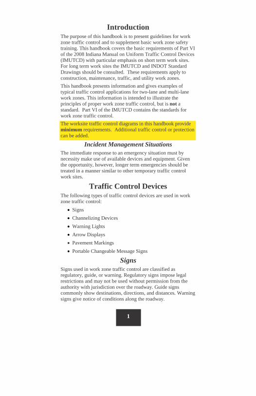
Introduction The purpose of this handbook is to present guidelines for work zone traffic control and to supplement basic work zone safety training. This handbook covers the basic requirements of Part VI of the 2008 Indiana Manual on Uniform Traffic Control Devices (IMUTCD) with particular emphasis on short term work sites. For long term work sites the IMUTCD and INDOT Standard Drawings should be consulted. These requirements apply to construction, maintenance, traffic, and utility work zones. This handbook presents information and gives examples of typical traffic control applications for two-lane and multi-lane work zones. This information is intended to illustrate the principles of proper work zone traffic control, but is not a standard. Part VI of the IMUTCD contains the standards for work zone traffic control. The worksite traffic control diagrams in this handbook provide minimum requirements. Additional traffic control or protection can be added.
Incident Management Situations The immediate response to an emergency situation must by necessity make use of available devices and equipment. Given the opportunity, however, longer term emergencies should be treated in a manner similar to other temporary traffic control work sites.
Traffic Control Devices The following types of traffic control devices are used in work zone traffic control:
• Signs • Channelizing Devices • Warning Lights • Arrow Displays • Pavement Markings • Portable Changeable Message Signs
Signs Signs used in work zone traffic control are classified as regulatory, guide, or warning. Regulatory signs impose legal restrictions and may not be used without permission from the authority with jurisdiction over the roadway. Guide signs commonly show destinations, directions, and distances. Warning signs give notice of conditions along the roadway.
2
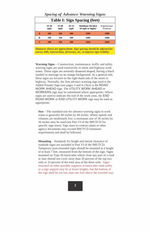
Spacing of Advance Warning Signs
Distances shown are approximate. Sign spacing should be adjusted for curves, hills, intersections, driveways, etc., to improve sign visibility.
Warning Signs – Construction, maintenance, traffic and utility warning signs are used extensively in street and highway work zones. These signs are normally diamond shaped, having a black symbol or message on an orange background. As a general rule, these signs are located on the right-hand side of the street or highway. Normally, the first advance warning sign used is the Added Penalty Sign (see pages 3 and 4.) Next is the ROAD WORK AHEAD sign. The UTILITY WORK AHEAD or WORKERS sign may be substituted where appropriate. Where signs are used to indicate the end of the work zone, the END ROAD WORK or END UTILITY WORK sign may be used as appropriate.
Size – The standard size for advance warning signs in work zones is generally 48 inches by 48 inches. Where speeds and volumes are moderately low, a minimum size of 36 inches by 36 inches may be used (see Part VI of the IMUTCD for specific sign sizes). Sign sizes in contract plans or other agency documents may exceed IMUTCD minimum requirements and shall be followed.
Mounting – Standards for height and lateral clearance of roadside signs are included in Part VI of the IMUTCD. Temporary post-mounted signs should be mounted at a height of at least 7 feet, measured from the bottom of the sign. Signs mounted on Type III barricades which close any part of a road or lane should not cover more than 50 percent of the top two rails or 33 percent of the total area of the three rails. Signs mounted on other portable supports or barricades used solely as a sign support may be at lower heights, but the bottom of the sign shall be not less than one foot above the traveled way.
Table I: Sign Spacing (feet)
25-30 mph
35-40 mph
45-55 mph
Multilane Divided 50 mph or higher
Expressway/ Freeway
A 100 350 500 1000 1000
B 100 350 500 1600 1600
C 100 350 500 2640 2640
3
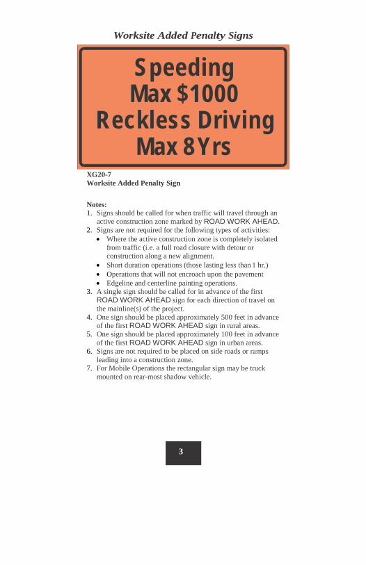
Speeding Max $1000
Reckless Driving Max 8 Yrs
Worksite Added Penalty Signs
XG20-7 Worksite Added Penalty Sign
Notes: 1. Signs should be called for when traffic will travel through an
active construction zone marked by ROAD WORK AHEAD. 2. Signs are not required for the following types of activities:
• Where the active construction zone is completely isolated from traffic (i.e. a full road closure with detour or construction along a new alignment.
• Short duration operations (those lasting less than 1 hr.) • Operations that will not encroach upon the pavement • Edgeline and centerline painting operations.
3. A single sign should be called for in advance of the first ROAD WORK AHEAD sign for each direction of travel on the mainline(s) of the project.
4. One sign should be placed approximately 500 feet in advance of the first ROAD WORK AHEAD sign in rural areas.
5. One sign should be placed approximately 100 feet in advance of the first ROAD WORK AHEAD sign in urban areas.
6. Signs are not required to be placed on side roads or ramps leading into a construction zone.
7. For Mobile Operations the rectangular sign may be truck mounted on rear-most shadow vehicle.
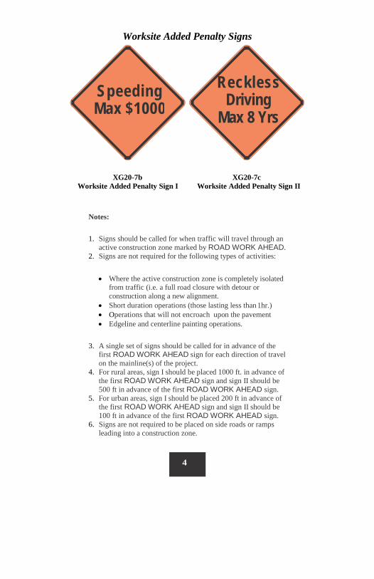
Reckless Driving
Max 8 Yrs Speeding Max $1000
4
Worksite Added Penalty Signs
XG20-7b XG20-7c
Worksite Added Penalty Sign I Worksite Added Penalty Sign II
Notes:
1. Signs should be called for when traffic will travel through an active construction zone marked by ROAD WORK AHEAD.
2. Signs are not required for the following types of activities:
• Where the active construction zone is completely isolated from traffic (i.e. a full road closure with detour or construction along a new alignment.
• Short duration operations (those lasting less than 1hr.) • Operations that will not encroach upon the pavement • Edgeline and centerline painting operations.
3. A single set of signs should be called for in advance of the first ROAD WORK AHEAD sign for each direction of travel on the mainline(s) of the project.
4. For rural areas, sign I should be placed 1000 ft. in advance of the first ROAD WORK AHEAD sign and sign II should be 500 ft in advance of the first ROAD WORK AHEAD sign.
5. For urban areas, sign I should be placed 200 ft in advance of the first ROAD WORK AHEAD sign and sign II should be 100 ft in advance of the first ROAD WORK AHEAD sign.
6. Signs are not required to be placed on side roads or ramps leading into a construction zone.

5
ROAD WORK 500 FT
ROAD CLOSED 500 FT
RIGHT LANE CLOSED 500 FT
6’
DETOUR 500 FT
35 MPH
6' M
IN
7' M
IN
Walkway
6’ TO 12’
RURAL DISTRICT RURAL DISTRICT WITH ADVISORY SPEED PLATE
Paved Shoulder
6’ TO 12’
2’ 2’ 7'
MIN
7' M
IN
URBAN DISTRICT URBAN DISTRICT
Removal – When work is suspended for short periods, all signs that are no longer appropriate shall be removed, covered, turned, or laid flat so they are not visible to drivers. Signs laid flat should not be placed such that posts present a danger to a motorist if they run over the sign.
Illumination and Retroreflectorization – All signs used during the hours of darkness shall be made of retroreflective material or illuminated. (Street or highway lighting is not regarded as meeting the requirements for sign illumination.)
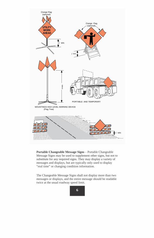
Orange Flag
(optional)
Orange Flag (optional)
WORK AHEAD
1' MIN
1' MIN
PORTABLE AND TEMPORARY
MOUNTINGS HIGH LEVEL WARNING DEVICE (Flag Tree)
1' MIN
UTILITY
6
8’M
IN
Portable Changeable Message Signs – Portable Changeable Message Signs may be used to supplement other signs, but not to substitute for any required signs. They may display a variety of messages and displays, but are typically only used to display “real time” or changing condition information.
The Changeable Message Signs shall not display more than two messages or displays, and the entire message should be readable twice at the usual roadway speed limit.
7
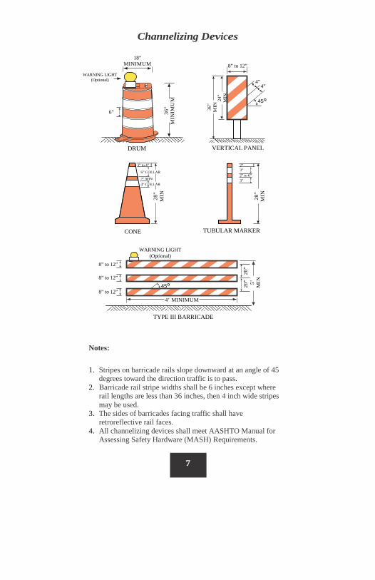
Channelizing Devices
Notes:
1. Stripes on barricade rails slope downward at an angle of 45 degrees toward the direction traffic is to pass.
2. Barricade rail stripe widths shall be 6 inches except where rail lengths are less than 36 inches, then 4 inch wide stripes may be used.
3. The sides of barricades facing traffic shall have retroreflective rail faces.
4. All channelizing devices shall meet AASHTO Manual for Assessing Safety Hardware (MASH) Requirements.
18” MINIMUM
WARNING LIGHT (Optional)
36”
MIN
IMU
M
6”
DRUM
8” to 12”
VERTICAL PANEL
24”
MIN
4” 4”
45
36”
MIN
TUBULAR MARKER 28
” M
IN
3”
3” 2”
2” to 6”
WARNING LIGHT (Optional)
TYPE III BARRICADE
20”
20” 5’
MIN
4’ MINIMUM 45
8” to 12” 8” to 12” 8” to 12”
CONE
28”
MIN 4” COLLAR
2” MIN
6” COLLAR
3” to 4”
8
Channelizing Devices Channelizing devices are used to warn and alert road users of conditions created by work activities and to guide road users. Channelizing devices include cones, tubular markers, vertical panels, drums, barricades, and barriers.
Cones are used most commonly for short-duration maintenance and utility work. Cones used at night shall be retroreflectorized as shown on page 7. Drums are used most commonly where they will remain in place for a prolonged period. Ballast shall not be placed on top of channelizing devices.
Spacing
The spacing of channelizing devices (cones, etc.) should be a distance in feet equal to the speed limit in mph when used for taper channelization, and a distance in feet equal to 2.0 times the speed limit in mph when used for tangent channelization. See Table II on Page 13. Alternatively, the spacing may be as follows: Spacing for straight-a-ways: • 20 to 40 mph: 1 cone for every 40’ (every skip) • 40 to 55 mph: 1 cone for every 80’ (every other skip) • 60 mph & above: 1 cone for every 120’ (every 3 skips)
Common Conversions:
1 skip = 10’ Gap between skips = 30’
RPM spacing (No Passing Zone) = 40’ RPM spacing (Passing Zone) = 80’
0.1 mile = 528’ 0.2 mile = 1056’ 0.3 mile = 1584’ 0.4 mile = 2112’ 0.5 mile = 2640’
0.6 mile = 3168’ 0.7 mile = 3696’ 0.8 mile = 4224’ 0.9 mile = 4752’ 1.0 mile = 5280’
9
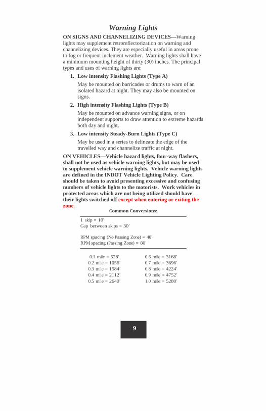
Warning Lights ON SIGNS AND CHANNELIZING DEVICES—Warning lights may supplement retroreflectorization on warning and channelizing devices. They are especially useful in areas prone to fog or frequent inclement weather. Warning lights shall have a minimum mounting height of thirty (30) inches. The principal types and uses of warning lights are:
1. Low intensity Flashing Lights (Type A) May be mounted on barricades or drums to warn of an isolated hazard at night. They may also be mounted on signs.
2. High intensity Flashing Lights (Type B) May be mounted on advance warning signs, or on independent supports to draw attention to extreme hazards both day and night.
3. Low intensity Steady-Burn Lights (Type C) May be used in a series to delineate the edge of the travelled way and channelize traffic at night.
ON VEHICLES—Vehicle hazard lights, four-way flashers, shall not be used as vehicle warning lights, but may be used to supplement vehicle warning lights. Vehicle warning lights are defined in the INDOT Vehicle Lighting Policy. Care should be taken to avoid presenting excessive and confusing numbers of vehicle lights to the motorists. Work vehicles in protected areas which are not being utilized should have their lights switched off except when entering or exiting the zone.
10
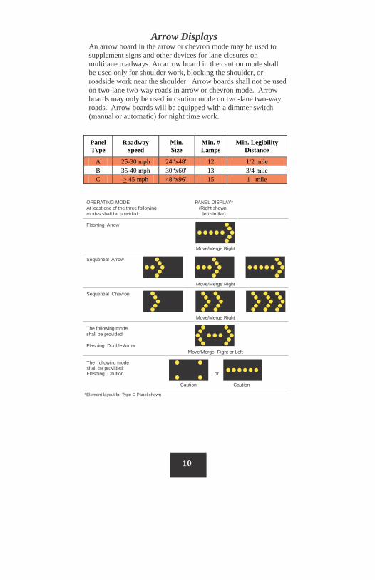
OPERATING MODE PANEL DISPLAY* At least one of the three following (Right shown; modes shall be provided: left similar)
Flashing Arrow
Move/Merge Right
Sequential Arrow
Move/Merge Right
Sequential Chevron
Move/Merge Right
The following mode shall be provided:
Flashing Double Arrow
Move/Merge Right or Left
The following mode shall be provided: Flashing Caution or
Caution Caution
*Element layout for Type C Panel shown
Arrow Displays An arrow board in the arrow or chevron mode may be used to supplement signs and other devices for lane closures on multilane roadways. An arrow board in the caution mode shall be used only for shoulder work, blocking the shoulder, or roadside work near the shoulder. Arrow boards shall not be used on two-lane two-way roads in arrow or chevron mode. Arrow boards may only be used in caution mode on two-lane two-way roads. Arrow boards will be equipped with a dimmer switch (manual or automatic) for night time work.
Panel Type
Roadway Speed
Min. Size
Min. # Lamps
Min. Legibility Distance
A 25-30 mph 24“x48" 12 1/2 mile B 35-40 mph 30“x60" 13 3/4 mile C > 45 mph 48“x96" 15 1 mile
11
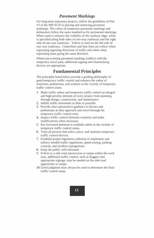
Pavement Markings For long-term stationary projects, follow the guidelines of Part VI of the IMUTCD in placing and removing pavement markings. The colors of temporary pavement markings and delineators follow the same standard as for permanent markings. When used to enhance the visibility of the roadway edge, white is specified along both sides of two-way roadways and the right side of one-way roadways. Yellow is used on the left side of one-way roadways. Centerlines and lane lines are yellow when separating opposing directions of traffic and white when separating lanes going the same direction. Where pre-existing pavement marking conflicts with the temporary travel path, additional signing and channelizing devices are appropriate.
Fundamental Principles The principles listed below provide a guiding philosophy of good temporary traffic control and enhance the safety of motorists, pedestrians, and workers in the vicinity of temporary traffic control zones. 1. Make traffic safety and temporary traffic control an integral
and high-priority element of every project from planning through design, construction, and maintenance.
2. Inhibit traffic movement as little as possible. 3. Provide clear and positive guidance to drivers and
pedestrians as they approach and travel through the temporary traffic control zone.
4. Inspect traffic control elements routinely and make modifications when necessary.
5. Pay increased attention to roadside safety in the vicinity of temporary traffic control zones.
6. Train all persons that select, place, and maintain temporary traffic control devices.
7. Establish proper legislative authority to implement and enforce needed traffic regulations, speed zoning, parking controls, and incident management.
8. Keep the public well informed. 9. If there is a side road intersection or ramps within the work
area, additional traffic control, such as flaggers and appropriate signage, may be needed on the side road approaches or ramps.
10. Good judgment must always be used to determine the final traffic control setup.
12
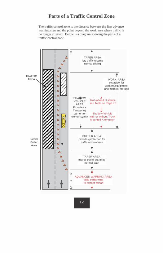
Roll-Ahead Distance see Table on Page 72
Shadow Vehicle with or without Truck Mounted Attenuator
TAPER AREA lets traffic resume
normal driving
BUFFER AREA provides protection for
traffic and workers
TAPER AREA
moves traffic out of its normal path
ADVANCED WARNING AREA tells traffic what to expect ahead
SHADOW VEHICLE
AREA Provides a Temporary barrier for
worker safety
Lateral Buffer Area
TRAFFIC AREA
Parts of a Traffic Control Zone
The traffic control zone is the distance between the first advance warning sign and the point beyond the work area where traffic is no longer affected. Below is a diagram showing the parts of a traffic control zone.
WORK AREA set aside for
workers,equipment, and material storage
13
Taper Length Criteria
for Work Zones
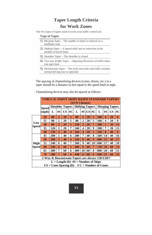
The five types of tapers used in work zone traffic control are:
Type of Taper 1) Merging Taper – The number of lanes is reduced on a
multilane road
2) Shifting Taper – A lateral shift, but no reduction in the number of travel lanes
3) Shoulder Taper – The shoulder is closed
4) Two-way Traffic Taper – Opposing directions of traffic share one open lane
5) Downstream Taper – The work area ends and traffic resumes normal driving (use is optional)
The spacing of channelizing devices (cones, drums, etc.) in a taper should be a distance in feet equal to the speed limit in mph. Channelizing devices may also be spaced as follows:
TABLE II: INDOT SKIPS BASED STANDARD TAPERS (12 Ft Closure)
Speed (mph)
Shoulder Tapers Shifting Tapers Merging Tapers
L #S CS #C L #S CS #C L #S CS #C
Low Speed
20 80 2 20 5 80 2 20 5 160 4 20 9 25 80 2 20 5 80 2 20 5 160 4 20 9 30 80 2 20 5 120 3 20 7 200 5 20 11 35 120 3 20 7 160 4 20 9 280 7 20 15 40 120 3 40 4 160 4 40 5 320 8 40 9
High Speed
45 200 5 40 6 280 7 40 8 560 14 40 16 50 200 5 40 6 320 8 40 9 600 15 40 17 55 240 6 40 7 360 9 40 10 680 17 40 18 60 240 6 60 5 360 9 60 7 720 18 60 13 65 280 7 60 6 400 10 60 8 800 20 60 15 70 280 7 60 6 440 11 60 9 840 21 60 15
2-Way & Downstream Tapers are always 120/3/20/7 L = Length (ft) #S = Number of Skips
CS = Cone Spacing (ft) # C = Number of Cones
14
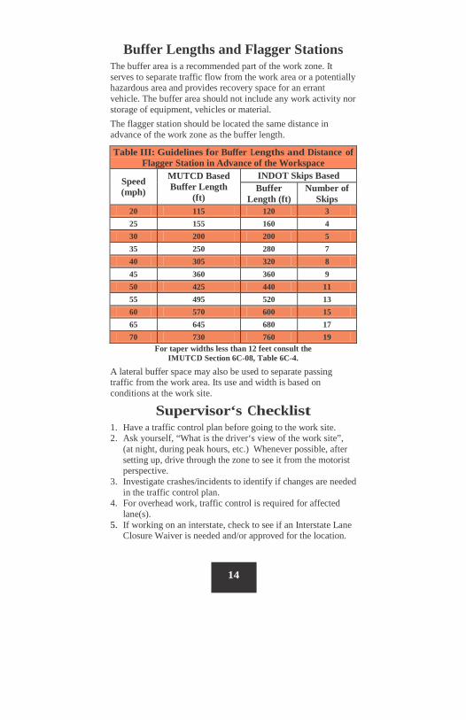
Buffer Lengths and Flagger Stations
The buffer area is a recommended part of the work zone. It serves to separate traffic flow from the work area or a potentially hazardous area and provides recovery space for an errant vehicle. The buffer area should not include any work activity nor storage of equipment, vehicles or material. The flagger station should be located the same distance in advance of the work zone as the buffer length.
For taper widths less than 12 feet consult the IMUTCD Section 6C-08, Table 6C-4.
A lateral buffer space may also be used to separate passing traffic from the work area. Its use and width is based on conditions at the work site.
Supervisor‘s Checklist 1. Have a traffic control plan before going to the work site. 2. Ask yourself, “What is the driver‘s view of the work site”,
(at night, during peak hours, etc.) Whenever possible, after setting up, drive through the zone to see it from the motorist perspective.
3. Investigate crashes/incidents to identify if changes are needed in the traffic control plan.
4. For overhead work, traffic control is required for affected lane(s).
5. If working on an interstate, check to see if an Interstate Lane Closure Waiver is needed and/or approved for the location.
Table III: Guidelines for Buffer Lengths and Distance of Flagger Station in Advance of the Workspace
Speed (mph)
MUTCD Based Buffer Length
(ft)
INDOT Skips Based Buffer
Length (ft) Number of
Skips 20 115 120 3 25 155 160 4 30 200 200 5 35 250 280 7 40 305 320 8 45 360 360 9 50 425 440 11 55 495 520 13 60 570 600 15 65 645 680 17 70 730 760 19
15
Planning the Layout The key to good traffic control is to apply the guidelines using proper judgment. Consider factors such as duration of work, location of work, and characteristics of the roadway.
Duration of Work Work duration is a major factor in determining the number and types of devices used in temporary traffic control zones. As a general rule, the longer the operation will last, the more traffic control devices are needed. Also, as the work time is short, the time during which motorists are affected is significantly increased when additional devices are installed and removed. Considering these factors, it is generally held that simplified control procedures are warranted for short-duration activities. Such shortcomings may be offset by the use of other, more dominant devices, such as special lighting units on work vehicles.
Long-Term Stationary – Work that occupies a location more than three (3) days. Intermediate-Term Stationary – Work that occupies a location from overnight to three (3) days. Short-Term Stationary – Daytime work that occupies a location for one (1) to twelve (12) hours. Short Duration – Work that occupies a location up to one (1) hour. Mobile – Work that moves intermittently or continuously.
Location of Work
The choice of traffic control needed for a temporary traffic control zone depends upon where the work is located. As a general rule, the closer the work is to traffic, the more traffic control devices are needed.
16
What Traffic Control Set-Up Should I Use?
These five (5) questions should be considered and answered in order to provide proper worksite traffic control:
1. What is the type of road (two-lane or multi-lane) on which we will be working?
2. Are we working on the roadway or shoulder? 3. How long will we be at a location? 4. Is extra protection needed? 5. Is a lane being restricted or encroached upon?
Curvy and Hilly Locations These locations may require extra work zone safety measures.
17
Night Time Traffic Control Extra care should be taken when scheduling work at night. Plan ahead whenever possible, involving all affected personnel, to ensure that everyone understands what is expected of them and that you have the proper traffic control equipment for the job. As stated on page 1 of this manual, the immediate response to an emergency situation must by necessity make use of available devices and equipment. Given the opportunity, however, longer term emergencies should be treated in a manner similar to temporary traffic control as soon as possible. The work zone controls mentioned in this manual are the minimum requirements and extra controls should be utilized when needed. Closing additional lanes when possible and the use of message boards are just 2 of the tools available. Specifically the following are guidelines to follow when performing night time activities: Signs: Must be retroreflective (see page 5 of this manual for more details) Message Boards: Portable message signs may be used to alert the public of the work ahead. See page 6 for specific details and how the sign should be used. It can be a good practice to display a message a day ahead of the work warning about the coming change. Arrow Boards: Lights should be dimmed for night operations (most boards dim automatically). Personal Protective Equipment: Hi-viz safety apparel shall be worn during night time operations (consult the INDOT Safety Manual for specific details). Channelizing Devices: Cones must be 28” tall and have retroreflective tape. Barrels must have retroreflective tape or Warning Lights (as required). Barricade panel must be Type 3. (See page 7 of this manual for more details). It is also a good practice to have night patrols available to reset traffic control devices as needed. Lighting - Worksite Illumination: Portable light towers with generator should be used to illuminate the work area. The preferred light strength should be Class III 215 lux (20ft candles). Every effort shall be made to prevent glare affecting oncoming traffic.

18
Night Time Traffic Control (cont.) Vehicle Work Lights: Lights shall be added to work equipment as needed. Equipment lighting shall also be positioned to prevent glare to motorist. General Safety: Trucks pulling arrow board for night time operations should turn off all warning lights and flashers to the rear to prevent distracting from the view of the arrow board. Headlights should be on during mobile operations.
19
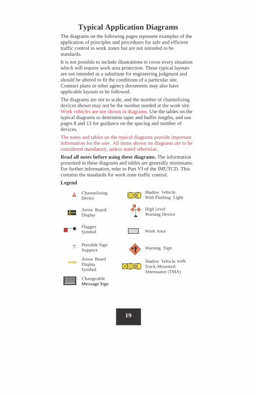
Shadow Vehicle With Flashing Light
High Level Warning Device
Work Area
Warning Sign
Shadow Vehicle with Truck-Mounted Attenuator (TMA)
Channelizing Device
Arrow Board Display
Flagger Symbol
Portable Sign Support
Arrow Board Display Symbol
Changeable Message Sign
Typical Application Diagrams The diagrams on the following pages represent examples of the application of principles and procedures for safe and efficient traffic control in work zones but are not intended to be standards. It is not possible to include illustrations to cover every situation which will require work area protection. These typical layouts are not intended as a substitute for engineering judgment and should be altered to fit the conditions of a particular site. Contract plans or other agency documents may also have applicable layouts to be followed. The diagrams are not to scale, and the number of channelizing devices shown may not be the number needed at the work site. Work vehicles are not shown in diagrams. Use the tables on the typical diagrams to determine taper and buffer lengths, and use pages 8 and 13 for guidance on the spacing and number of devices. The notes and tables on the typical diagrams provide important information for the user. All items shown on diagrams are to be considered mandatory, unless stated otherwise. Read all notes before using these diagrams. The information presented in these diagrams and tables are generally minimums. For further information, refer to Part VI of the IMUTCD. This contains the standards for work zone traffic control. Legend

20
Shadow vehicle for INDOT shall have a minimum weight of 10,000 lbs. A load of sand may be required to obtain the minimum weight, but it should not be permitted to freeze during winter operations. If a TMA is used, the truck shall be loaded per the TMA manufacturer’s specifications. Shadow vehicles should be parked parallel to traffic and have the front wheels angled away from traffic.
Definitions of Terms Shall/Mandatory - Required condition. Should/Recommend - An advisory condition. Where these words are used, they are considered to be advisable usage. May/Optional - A permissive condition. No requirement for design or application is intended. Not for INDOT use - Not for use on INDOT roads. For work not specifically covered in this WZTCH, the IMUTCD will need to be consulted, but where this WZTCH has added devices, etc, this WZTCH shall take precedence.

Short Term Stationary (1 to 12 hours)
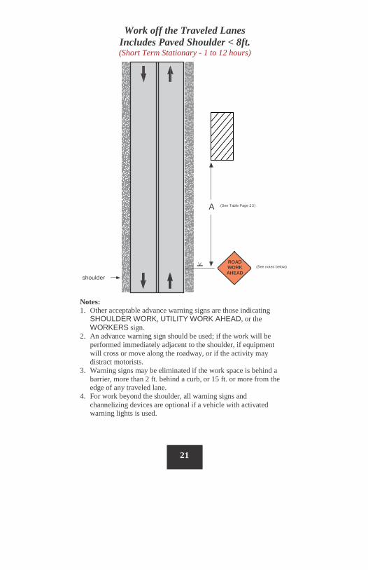
Work off the Traveled Lanes Includes Paved Shoulder < 8ft. (Short Term Stationary - 1 to 12 hours)
Notes: 1. Other acceptable advance warning signs are those indicating
SHOULDER WORK, UTILITY WORK AHEAD, or the WORKERS sign.
2. An advance warning sign should be used; if the work will be performed immediately adjacent to the shoulder, if equipment will cross or move along the roadway, or if the activity may distract motorists.
3. Warning signs may be eliminated if the work space is behind a barrier, more than 2 ft. behind a curb, or 15 ft. or more from the edge of any traveled lane.
4. For work beyond the shoulder, all warning signs and channelizing devices are optional if a vehicle with activated warning lights is used.
21
(See Table Page 23)
shoulder
A
_
ROAD WORK AHEAD (See notes below)
Shoulder or
(See Note 1)
ROAD
A
22
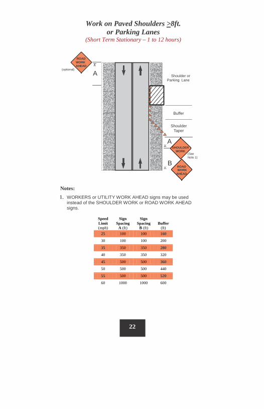
Work on Paved Shoulders >8ft. or Parking Lanes
(Short Term Stationary – 1 to 12 hours)
ROAD WORK AHEAD
(optional)
Parking Lane
Buffer
Shoulder
Taper
A SHOULDER
WORK
B WORK
AHEAD
Notes: 1. WORKERS or UTILITY WORK AHEAD signs may be used
instead of the SHOULDER WORK or ROAD WORK AHEAD signs.
Speed Limit (mph)
Sign Spacing
A (ft)
Sign Spacing
B (ft) Buffer
(ft) 25 100 100 160
30 100 100 200
35 350 350 280
40 350 350 320
45 500 500 360
50 500 500 440
55 500 500 520
60 1000 1000 600
A
ROAD WORK AHEAD
23
Roll Ahead Distance (See Table Page 72)
Shoulder Taper
½ A
SHOULDER CLOSED
Buffer
SHOULDER CLOSED AHEAD
ROAD WORK AHEAD
B
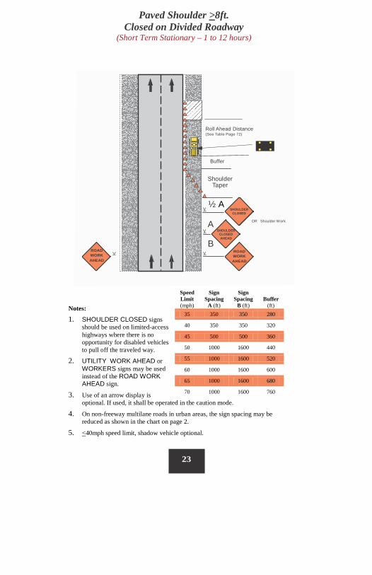
Notes:
1. SHOULDER CLOSED signs should be used on limited-access highways where there is no opportunity for disabled vehicles to pull off the traveled way.
2. UTILITY WORK AHEAD or WORKERS signs may be used instead of the ROAD WORK AHEAD sign.
3. Use of an arrow display is optional. If used, it shall be operated in the caution mode.
4. On non-freeway multilane roads in urban areas, the sign spacing may be reduced as shown in the chart on page 2.
5. <40mph speed limit, shadow vehicle optional.
OR Shoulder Work
Paved Shoulder >8ft. Closed on Divided Roadway
(Short Term Stationary – 1 to 12 hours)
Speed Limit (mph)
Sign Spacing
A (ft)
Sign Spacing
B (ft) Buffer
(ft) 35 350 350 280
40 350 350 320
45 500 500 360
50 1000 1600 440
55 1000 1600 520
60 1000 1600 600
65 1000 1600 680
70 1000 1600 760
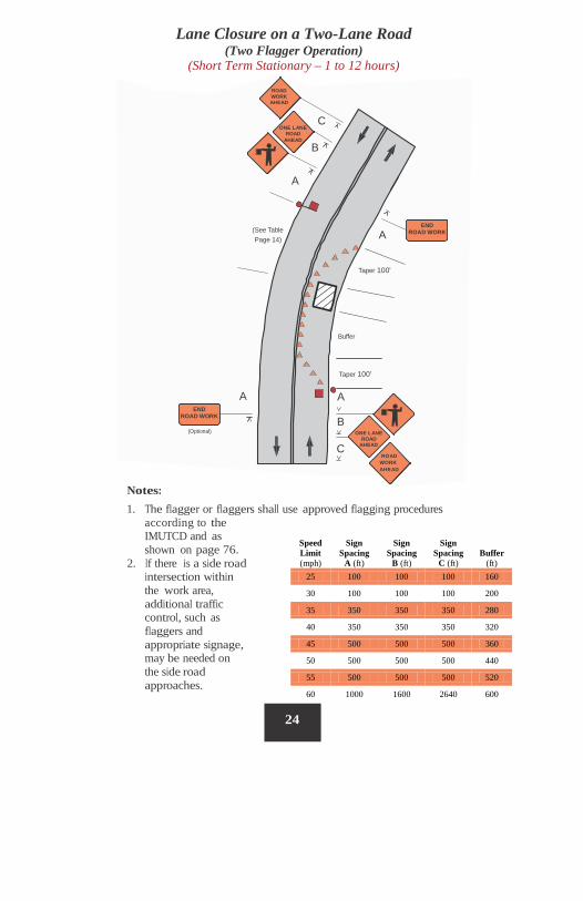
Notes: 1. The flagger or flaggers shall use approved flagging procedures
according to the IMUTCD and as shown on page 76.
2. If there is a side road intersection within the work area, additional traffic control, such as flaggers and appropriate signage, may be needed on the side road approaches.
Lane Closure on a Two-Lane Road (Two Flagger Operation)
(Short Term Stationary – 1 to 12 hours)
C ONE LANE
ROAD AHEAD
B
A
END ROAD WORK (See Table
Page 14) A
Taper 100'
Buffer
Taper 100'
A A END
ROAD WORK B (Optional) ONE LANE
ROAD AHEAD
ROAD WORK AHEAD
C
24
Speed Limit (mph)
Sign Spacing
A (ft)
Sign Spacing
B (ft)
Sign Spacing
C (ft) Buffer
(ft) 25 100 100 100 160
30 100 100 100 200
35 350 350 350 280
40 350 350 350 320
45 500 500 500 360
50 500 500 500 440
55 500 500 500 520
60 1000 1600 2640 600
ROAD WORK AHEAD
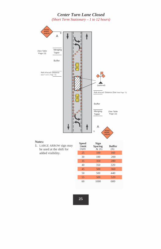
Center Turn Lane Closed (Short Term Stationary – 1 to 12 hours)
ROAD WORK AHEAD
A
Merging Taper
(See Table Page 13)
Buffer
Roll Ahea d Distance (See T a b l e Page 72)
(optional)
Roll Ahea d Distance (See Table Page 72)
Buffer
Merging Taper
(See Table Page 13)
A ROAD
WORK AHEAD
Notes: 1. LARGE ARROW sign may
be used at the shift for added visibility.
25
Speed Sign Limit Spacing Buffer (mph) A (ft) (ft)
25 100 160 30 100 200
35 350 280 40 350 320
45 500 360 50 500 440
55 500 520 60 1000 600
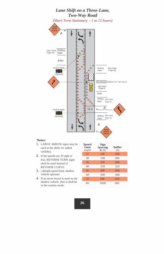
Lane Shift on a Three-Lane, Two-Way Road
(Short Term Stationary – 1 to 12 hours)
Speed Limit (mph)
Sign Spacing
A (ft)
Notes: 1. LARGE ARROW signs may be
used at the shifts for added visibility.
2. If the speeds are 30 mph or less, REVERSE TURN signs shall be used instead of REVERSE CURVE.
3. <40mph speed limit, shadow vehicle optional.
4. If an arrow board is used on the shadow vehicle, then it shall be in the caution mode.
Buffer (ft)
30 100 200
40 350 320
50 500 440
60 1000 600
26
55 500 520
45 500 360
35 350 280
25 100 160
ROADWORK AHEAD
A
Shifting Taper
Buffer
Caution Mode Shifting (See Table Taper Page 13)
(Optional)
Roll Ahead Distance (See Table Page 72)
(See Note Page 6)
Buffer
Shifting Taper
Caution Mode A
Shifting Taper
(Optional)
A ROAD
WORK AHEAD
½ L
(See Table Page 13)
(See Table Page 13)
(See Table Page 13)
ROADWORK AHEAD
ROAD WORK AHEAD (See Note 1) C
LEFT LANE CLOSED AHEAD
B
A
Merging Taper
(See Table Page 14)
Buffer Space (optional)
Roll Ahead Distance ( See Table Page 72)
Shadow Vehicle Area (See Note 2)
(See Table Page 14) Buffer Space
Merging Taper
A
B (See Note 1)
C ROAD WORK AHEAD
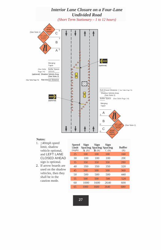
Notes: 1. <40mph speed
limit, shadow vehicle optional, and LEFT LANE CLOSED AHEAD sign is optional.
2. If arrow boards are used on the shadow vehicles, then they shall be in the caution mode.
Speed Sign Sign Sign Limit Spacing Spacing Spacing Buffer
(ft) (mph) A (ft) B (ft) C (ft)
30 100 100 100 200
40 350 350 350 320
50 500 500 500 440
60 1000 1600 2640 600
27
65 1000 1600 2640 680
55 500 500 500 520
45 500 500 500 360
35 350 350 350 280
25 100 100 100 160
Interior Lane Closure on a Four-Lane Undivided Road
(Short Term Stationary – 1 to 12 hours)
LEFT LANE CLOSED AHEAD
(optional) Shadow Vehicle Area (See Note 2)
(See Table Page 72) Roll Ahead Distance
(optional)
(optional)
Buffer Merging Taper
Shoulder Taper (optional)
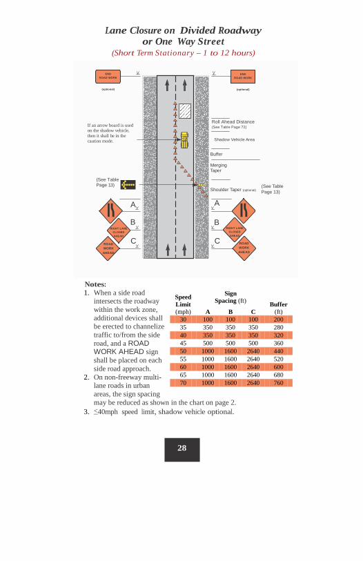
Lane Closure on Divided Roadway or One Way Street
(Short Term Stationary – 1 to 12 hours)
If an arrow board is used on the shadow vehicle, then it shall be in the caution mode.
(See Table Page 13) (See Table
Page 13)
28
A B
B
C
C
ROAD WORK AHEAD
A
RIGHT LANE CLOSED AHEAD
ROAD WORK AHEAD
Roll Ahead Distance (See Table Page 72)
RIGHT LANE CLOSED AHEAD
END ROAD WORK
(optional)
END ROAD WORK
(optional)
Shadow Vehicle Area
Speed Limit (mph)
Sign Spacing (ft) Buffer
(ft) A B C 30 100 100 100 200 35 350 350 350 280 40 350 350 350 320 45 500 500 500 360 50 1000 1600 2640 440 55 1000 1600 2640 520 60 1000 1600 2640 600 65 1000 1600 2640 680 70 1000 1600 2640 760
Notes: 1. When a side road
intersects the roadway within the work zone, additional devices shall be erected to channelize traffic to/from the side road, and a ROAD WORK AHEAD sign shall be placed on each side road approach.
2. On non-freeway multi- lane roads in urban areas, the sign spacing may be reduced as shown in the chart on page 2.
3. <40mph speed limit, shadow vehicle optional.
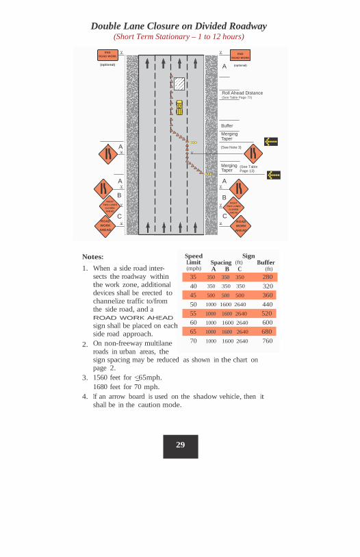
Double Lane Closure on Divided Roadway (Short Term Stationary – 1 to 12 hours)
C
Speed Limit (mph)
Sign Spacing (ft) Buffer
Notes: 1. When a side road inter-
sects the roadway within the work zone, additional devices shall be erected to channelize traffic to/from the side road, and a ROAD WORK AHEAD sign shall be placed on each side road approach. On non-freeway multilane roads in urban areas, the
A B C (ft)
40 320 350 350 350
50 440 1000 1600 2640
60 600 1000 1600 2640
70 760 1000 1600 2640 2.
sign spacing may be reduced as shown in the chart on page 2. 1560 feet for <65mph. 3. 1680 feet for 70 mph. If an arrow board is used on the shadow vehicle, then it shall be in the caution mode.
4.
29
65 1000 1600 2640 680
55 1000 1600 2640 520
45 500 500 500 360
35 350 350 350 280
A
Roll Ahead Distance (See Table Page 72)
Buffer
Merging Taper
A (See Note 3)
(See Table Page 13)
Merging Taper
A A
B
C
B
END ROAD WORK
(optional)
END
ROAD WORK
(optional)
ROAD WORK AHEAD
ROAD WORK AHEAD
RIGHT
TWO LANES CLOSED AHEAD
RIGHT
TWO LANES CLOSED AHEAD
1/2 Times Merging Taper Length Merging Taper
A
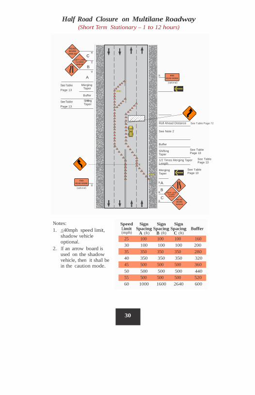
Half Road Closure on Multilane Roadway (Short Term Stationary – 1 to 12 hours)
Shifting Taper
See Table Page 13
See Table Page 13
Notes: 1. <40mph speed limit,
Speed Sign Sign Sign Limit Spacing Spacing Spacing Buffer (mph) A (ft) B (ft) C (ft) shadow vehicle
optional. 2. If an arrow board is
used on the shadow vehicle, then it shall be in the caution mode.
30 100 100 100 200
40 350 350 350 320
50 500 500 500 440
60 1000 1600 2640 600
30
55 500 500 500 520
45 500 500 500 360
35 350 350 350 280
25 100 100 100 160
ROAD WORK AHEAD
END ROAD WORK
(optional)
LEFT LANE CLOSED AHEAD
C B
A
See Table Page 13
Merging Taper Buffer
RIGHT LANE CLOSED AHEAD
END ROAD WORK
(optional)
B
C
See Table Page 13
See Table Page 13
Roll Ahead Distance See Table Page 72
See Note 2
Buffer Shifting Taper
ROAD WORK AHEAD
Half Road Closure on Multilane Roadway (cont.) (Short Term Stationary – 1 to 12 hours)
Notes: 1. Channelizing devices shall be more closely spaced when the
pavement markings conflict with the temporary travel path. 2. When a side road intersects the roadway within the work
zone, additional devices shall be erected to channelize traffic to/from the side road and a ROAD WORK AHEAD sign shall be placed on each side road approach.
31
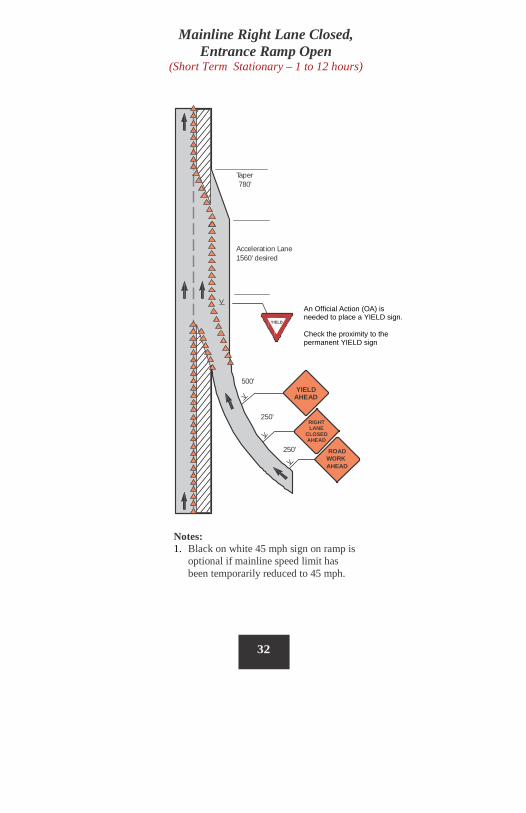
Mainline Right Lane Closed, Entrance Ramp Open
(Short Term Stationary – 1 to 12 hours)
Taper 780'
Acceleration Lane 1560' desired
YIELD
500' YIELD
AHEAD
250' RIGHT LANE
CLOSED AHEAD
250' ROAD WORK AHEAD
Notes: 1. Black on white 45 mph sign on ramp is
optional if mainline speed limit has been temporarily reduced to 45 mph.
32
An Official Action (OA) is needed to place a YIELD sign. Check the proximity to the permanent YIELD sign
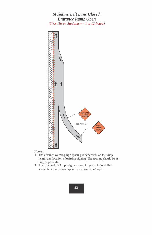
Mainline Left Lane Closed, Entrance Ramp Open
(Short Term Stationary – 1 to 12 hours)
LEFT LANE CLOSED AHEAD
see Note 1 ROAD WORK AHEAD
Notes: 1. The advance warning sign spacing is dependent on the ramp
length and location of existing signing. The spacing should be as long as possible.
2. Black on white 45 mph sign on ramp is optional if mainline speed limit has been temporarily reduced to 45 mph.
33
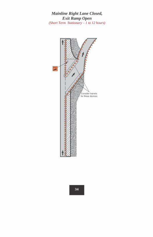
Mainline Right Lane Closed, Exit Ramp Open
(Short Term Stationary – 1 to 12 hours)
Consider barrels for these devices.
34
EXIT
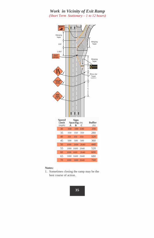
Work in Vicinity of Exit Ramp (Short Term Stationary – 1 to 12 hours)
Merging Taper
Merging Taper 100'
1,000'
XX
XX
Speed Limit (mph)
Sign Spacing (ft) A B C
Buffer (ft)
35 280 350 350 350
45 360 500 500 500
55 520 1000 1600 2640
65 680 1000 1600 2640
Notes: 1. Sometimes closing the ramp may be the
best course of action.
35
70 1000 1600 2640 760
60 1000 1600 2640 600
50 1000 1600 2640 440
40 350 350 350 320
30 100 100 100 200
Merging Taper
EXIT OPEN
Merging taper
100’
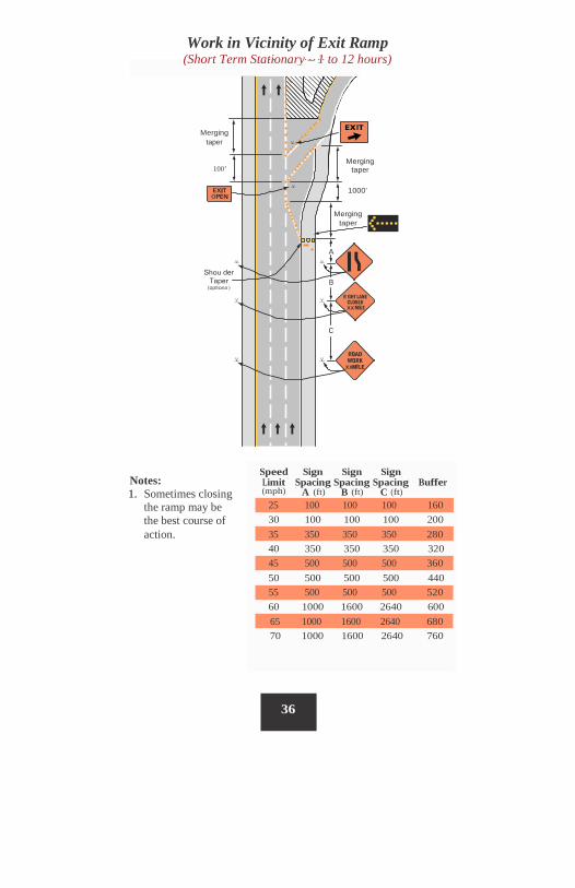
Work in Vicinity of Exit Ramp (Short Term Stationary – 1 to 12 hours)
Merging taper
Merging taper
Speed Sign Sign Sign Notes: 1. Sometimes closing
the ramp may be the best course of action.
Limit Spacing Spacing Spacing Buffer (mph) A (ft) B (ft) C (ft)
30 100 100 100 200
40 350 350 350 320
50 500 500 500 440
60 1000 1600 2640 600
70 1000 1600 2640 760
36
65 1000 1600 2640 680
55 500 500 500 520
45 500 500 500 360
35 350 350 350 280
25 100 100 100 160
1000’
XX
XX
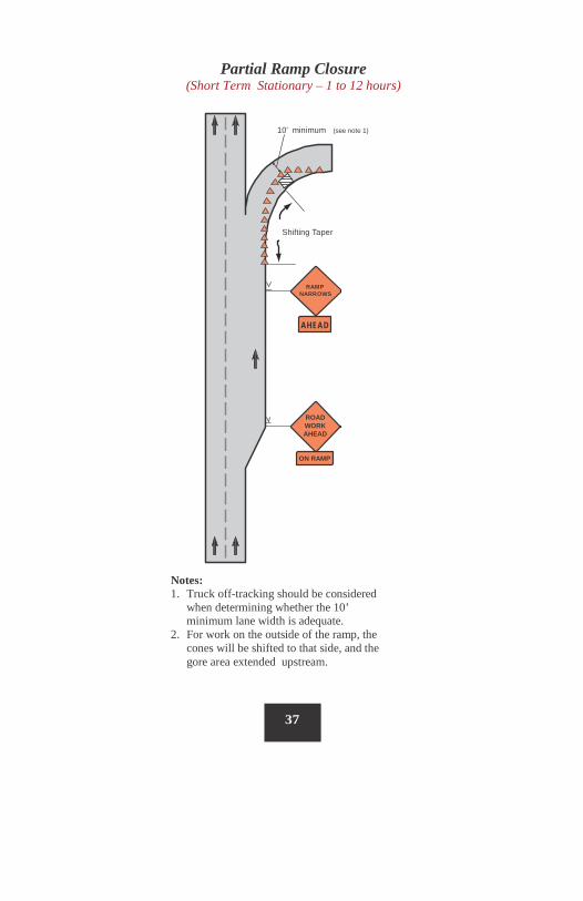
Partial Ramp Closure (Short Term Stationary – 1 to 12 hours)
10' minimum (see note 1)
Shifting Taper
RAMP NARROWS
AHEAD
ROAD WORK AHEAD
ON RAMP
Notes: 1. Truck off-tracking should be considered
when determining whether the 10’ minimum lane width is adequate.
2. For work on the outside of the ramp, the cones will be shifted to that side, and the gore area extended upstream.
37
Buffer
(ft) 120 170 220 280 335 415 485 580
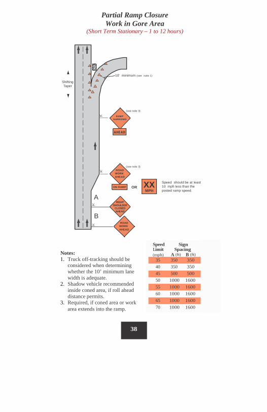
Partial Ramp Closure Work in Gore Area
(Short Term Stationary – 1 to 12 hours)
10' minimum (see note 1)
Shifting Taper
(see note 3)
RAMP NARROWS
AHEAD
(see note 3) ROAD
WORK AHEAD
XX MPH
Speed should be at least 10 mph less than the posted ramp speed.
ON RAMP OR
A RIGHT
SHOULDER CLOSED AHEAD
B ROAD
WORK AHEAD
1.
2.
38
Notes: 1. Truck off-tracking should be
considered when determining whether the 10’ minimum lane width is adequate.
2. Shadow vehicle recommended inside coned area, if roll ahead distance permits.
3. Required, if coned area or work area extends into the ramp.
Speed Sign Limit Spacing
(mph) A (ft) B (ft) 35 350 350 40 350 350 45 500 500 50 1000 1600 55 1000 1600 60 1000 1600 65 1000 1600 70 1000 1600
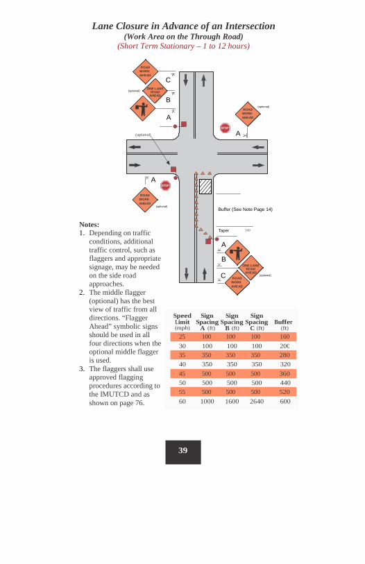
Lane Closure in Advance of an Intersection (Work Area on the Through Road)
(Short Term Stationary – 1 to 12 hours)
ROAD WORK AHEAD
C ONE LANE
ROAD AHEAD
(optional)
B (optional)
ROAD WORK AHEAD A
A (optional)
A
ROAD WORK AHEAD
Buffer (See Note Page 14) (optional)
Taper
Notes: 1. Depending on traffic
conditions, additional traffic control, such as flaggers and appropriate signage, may be needed on the side road approaches.
2. The middle flagger (optional) has the best view of traffic from all directions. “Flagger Ahead” symbolic signs should be used in all four directions when the optional middle flagger is used.
3. The flaggers shall use approved flagging procedures according to the IMUTCD and as shown on page 76.
100'
A
B ONE LANE
ROAD AHEAD C (optional)
ROAD WORK AHEAD
Speed Sign Sign Sign Limit Spacing Spacing Spacing Buffer (mph) A (ft) B (ft) C (ft) (ft)
30 100 100 100 200
40 350 350 350 320
50 500 500 500 440
60 1000 1600 2640 600
39
55 500 500 500 520
45 500 500 500 360
35 350 350 350 280
25 100 100 100 160
ROAD WORK AHEAD C
ONE LANE ROAD
AHEAD (optional)
B
ROAD WORK AHEAD
A
A B
B A ROAD
WORK AHEAD
Buffer (See Note Page 14)
Taper
A B
100'
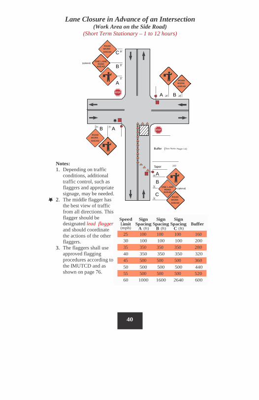
Notes: 1. Depending on traffic
conditions, additional traffic control, such as flaggers and appropriate signage, may be needed.
2. The middle flagger has the best view of traffic from all directions. This flagger should be designated lead flagger and should coordinate the actions of the other flaggers.
3. The flaggers shall use approved flagging procedures according to the IMUTCD and as shown on page 76.
ONE LANE ROAD
AHEAD (optional)
C ROAD
WORK AHEAD
Speed Sign Sign Sign Limit Spacing Spacing Spacing Buffer (mph) A (ft) B (ft) C (ft)
30 100 100 100 200
40 350 350 350 320
50 500 500 500 440
60 1000 1600 2640 600
40
55 500 500 500 520
45 500 500 500 360
35 350 350 350 280
25 100 100 100 160
Lane Closure in Advance of an Intersection (Work Area on the Side Road)
(Short Term Stationary – 1 to 12 hours)
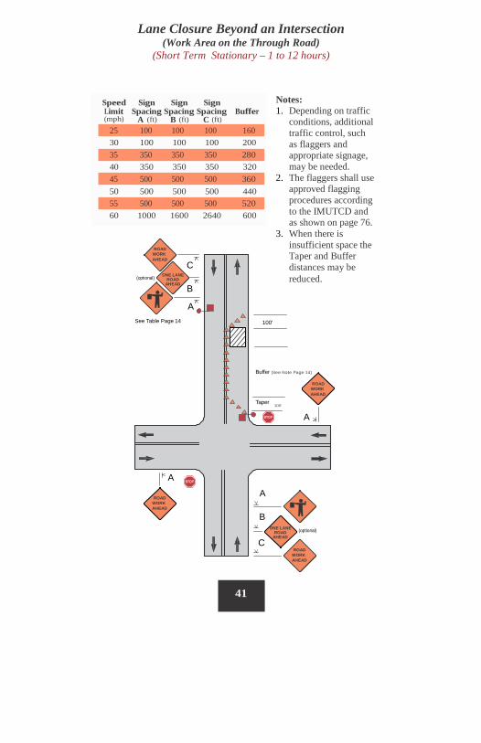
Lane Closure Beyond an Intersection (Work Area on the Through Road)
(Short Term Stationary – 1 to 12 hours)
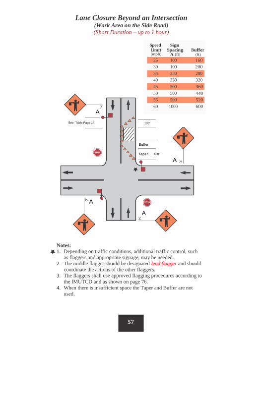
Notes: 1. Depending on traffic
conditions, additional traffic control, such as flaggers and appropriate signage, may be needed.
2. The flaggers shall use approved flagging procedures according to the IMUTCD and as shown on page 76.
3. When there is insufficient space the Taper and Buffer distances may be reduced.
Speed Sign Sign Sign Limit Spacing Spacing Spacing Buffer (mph) A (ft) B (ft) C (ft)
30 100 100 100 200
40 350 350 350 320
50 500 500 500 440
60 1000 1600 2640 600
ROAD
WORK AHEAD
C ONE LANE
ROAD AHEAD
(optional)
B A
See Table Page 14 100'
Buffer (See Note Page 14)
ROAD WORK AHEAD
Taper 100'
A
A
A ROAD
WORK AHEAD
B ONE LANE
ROAD AHEAD
(optional)
C ROAD
WORK AHEAD
41
55 500 500 500 520
45 500 500 500 360
35 350 350 350 280
25 100 100 100 160
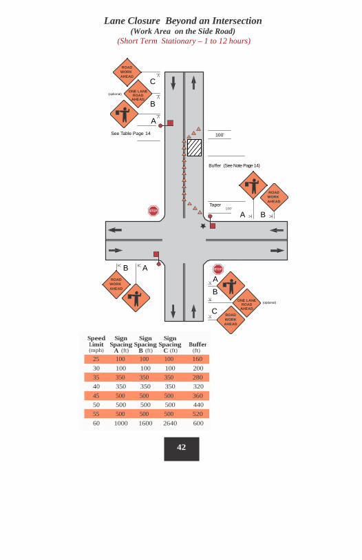
Lane Closure Beyond an Intersection (Work Area on the Side Road)
(Short Term Stationary – 1 to 12 hours)
ROAD WORK AHEAD
C ONE LANE
ROAD AHEAD
(optional)
B
A See Table Page 14 100'
Buffer (See Note Page 14)
ROAD WORK AHEAD
Taper 100'
A B
B A A ROAD
WORK AHEAD B
ONE LANE ROAD
AHEAD
(optional)
C ROAD WORK AHEAD
Speed Sign Sign Sign Limit Spacing Spacing Spacing Buffer (mph) A (ft) B (ft) C (ft) (ft)
30 100 100 100 200
40 350 350 350 320
50 500 500 500 440
60 1000 1600 2640 600
42
55 500 500 500 520
45 500 500 500 360
35 350 350 350 280
25 100 100 100 160
43
Lane Closure Beyond an Intersection (cont.) (Short Term Stationary – 1 to 12 hours)
Notes: 1. Depending on traffic conditions, additional traffic control, such
as flaggers and appropriate signage, may be needed. 2. The middle flagger should be designated lead flagger and
should coordinate the actions of the other flaggers. 3. The flaggers shall use approved flagging procedures according
to the IMUTCD and as shown on page 76. 4. When there is insufficient space the Taper and Buffer distances
may be reduced.
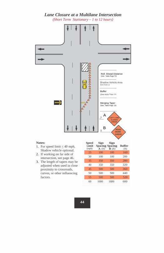
Notes: 1. For speed limit < 40 mph,
Shadow vehicle optional. 2. If working on far side of
intersection, see page 46. 3. The length of tapers may be
adjusted when used in close proximity to crossroads, curves, or other influencing factors.
Lane Closure at a Multilane Intersection (Short Term Stationary – 1 to 12 hours)
Roll Ahead Distance (See Table Page 72)
Buffer (See Note Page 14)
Merging Taper (See Table Page 13)
A LEFT LANE
CLOSED AHEAD
B ROAD WORK AHEAD
44
Shadow Vehicle Area
(See Note 2)
Speed Sign Sign Limit Spacing Spacing Buffer (mph) A (ft) B (ft) (ft)
25 100 100 160 30 100 100 200 35 350 350 280 40 350 350 320 45 500 500 360 50 500 500 440 55 500 500 520 60 1000 1600 600
25 100
35 350
45 500
55 500
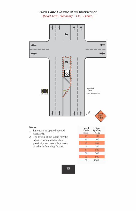
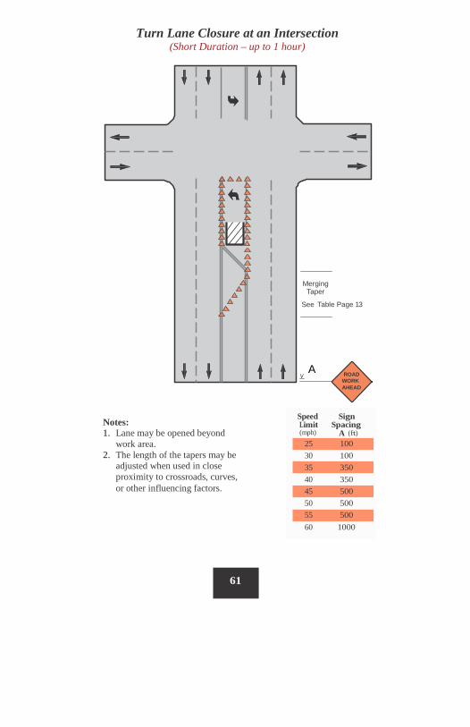
Turn Lane Closure at an Intersection (Short Term Stationary – 1 to 12 hours)
Merging Taper
(See Table Page 13) (Optional)
A ROAD WORK AHEAD
Notes: 1. Lane may be opened beyond
work area. 2. The length of the tapers may be
adjusted when used in close proximity to crossroads, curves, or other influencing factors.
45
Speed Sign Limit Spacing (mph) A (ft)
30 100
40 350
50 500
60 1000
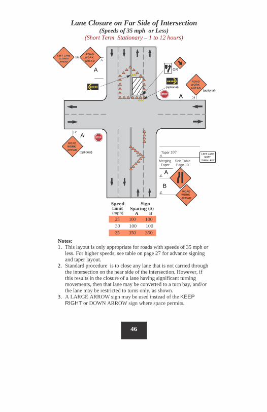
Lane Closure on Far Side of Intersection (Speeds of 35 mph or Less)
(Short Term Stationary – 1 to 12 hours)
ROAD WORK AHEAD
LEFT LANE CLOSED AHEAD
OR
A OR
ROAD WORK AHEAD (optional)
(optional)
A
A ROAD
WORK AHEAD
(optional) Taper 100' LEFT LANE MUST
TURN LEFT Merging See Table Taper Page 13
A
B ROAD
WORK AHEAD
Speed Limit (mph)
Sign Spacing (ft)
A B
30 100 100
Notes: 1. This layout is only appropriate for roads with speeds of 35 mph or
less. For higher speeds, see table on page 27 for advance signing and taper layout.
2. Standard procedure is to close any lane that is not carried through the intersection on the near side of the intersection. However, if this results in the closure of a lane having significant turning movements, then that lane may be converted to a turn bay, and/or the lane may be restricted to turns only, as shown.
3. A LARGE ARROW sign may be used instead of the KEEP RIGHT or DOWN ARROW sign where space permits.
46
35 350 350
25 100 100
Sign Spacing B (ft) 100 350 350 500 500 500 1600
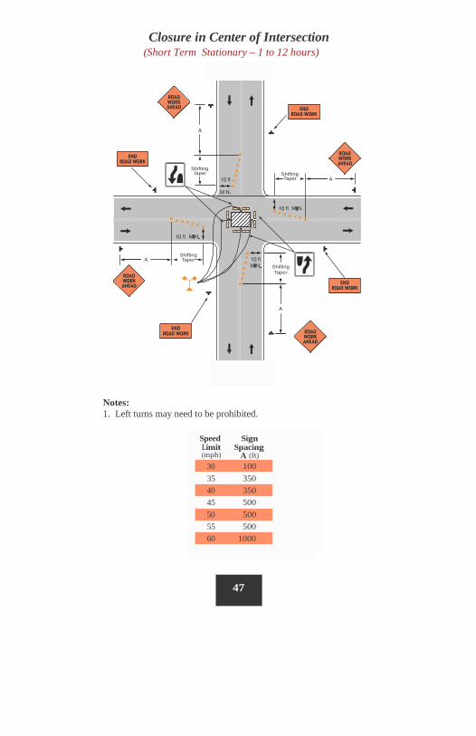
Closure in Center of Intersection (Short Term Stationary – 1 to 12 hours)
Shifting Shifting
Taper Shifting Taper
Notes: 1. Left turns may need to be prohibited.
(mph) A (ft)
47
Speed Sign Limit Spacing
30 100 35 350
40 350 45 500
50 500 55 500
60 1000
Taper
Shifting
Taper

Short Duration (up to 1 hour)
Sign Sign Spacing Spacing Buffer
B (ft) C (ft) 100 100 55 100 100 85 350 350 120 350 350 170 500 500 220 500 500 280 500 500 335
1600 2640 415
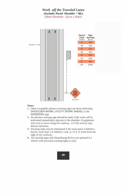
Work off the Traveled Lanes (Includes Paved Shoulder < 8ft.) (Short Duration - Up to 1 Hour)
(mph) A (ft)
Shoulder 30 100
40 350
50 500
60 1000
See Notes
Notes: 1. Other acceptable advance warning signs are those indicating
SHOULDER WORK, UTILITY WORK AHEAD, or the WORKERS sign.
2. An advance warning sign should be used; if the work will be performed immediately adjacent to the shoulder, if equipment will cross or move along the roadway, or if the activity may distract motorists.
3. Warning signs may be eliminated if the work space is behind a barrier, more than 2 ft. behind a curb, or 15 ft. or more from the edge of any roadway.
4. All warning signs and channelizing devices are optional if a vehicle with activated warning lights is used.
48
Speed Sign Limit Spacing
25 100
35 350
45 500
55 500
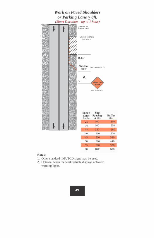
SHOULDER WORK
(See Table Page 13) Taper
(See Notes 1&2)
Notes: 1. Other standard IMUTCD signs may be used. 2. Optional when the work vehicle displays activated
warning lights.
49
(mph)
40 350 320 45 500 360 50 500 440 55 500 520 60 1000 600
Work on Paved Shoulders or Parking Lane > 8ft.
(Short Duration – up to 1 hour) Shoulder or
Parking Lane
Use of cones (See Note 2)
Sign Spacing Buffer
A (ft) (ft) 100 160 100 200 350 280
Buffer
Shoulder
A
Speed Limit
25 30 35
(optional)
(See Table Page 13)
SHOULDER WORK AHEAD
Optional when the work vehicle displays flashing
lights, strobes or beacon(s).
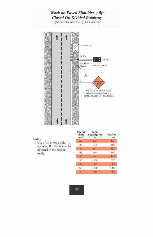
Speed Limit (mph)
Sign Spacing (ft)
A Buffer
(ft) Notes: 1. Use of an arrow display is
optional. If used, it shall be operated in the caution mode.
35 350 280
45 500 360
55 1000 520
65 1000 680
50
70 1000 760
60 1000 600
50 1000 440
40 350 320
30 100 200
cones optional
Buffer
: : Shoulder Taper
A
Work on Paved Shoulder > 8ft Closed On Divided Roadway
(Short Duration – up to 1 hour)
Roll Ahead Distance (See Table Page 72)
Buffer
Merging Taper
Shoulder Taper (optional) ( See Table Page 13)
A
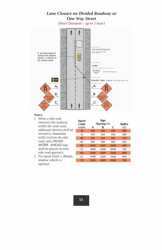
Lane Closure on Divided Roadway or One Way Street
(Short Duration – up to 1 hour)
ROAD WORK AHEAD
51
If an arrow board is used on the shadow vehicle, it shall be in the caution mode
(See Table Page 13)
A
B
B
RIGHT LANE CLOSED AHEAD
C
C
ROAD WORK AHEAD
RIGHT LANE CLOSED AHEAD
Speed Limit (mph)
Sign Spacing (ft) Buffer
(ft) A B C 30 100 100 100 200 35 350 350 350 280 40 350 350 350 320 45 500 500 500 360 50 1000 1600 2640 440 55 1000 1600 2640 520 60 1000 1600 2640 600 65 1000 1600 2640 680 70 1000 1600 2640 760
Notes: 1. When a side road
intersects the roadway within the work zone, additional devices shall be erected to channelize traffic to/from the side road, and a ROAD WORK AHEAD sign shall be placed on each side road approach.
2. For speed limits < 40mph, shadow vehicle is optional.
B
52
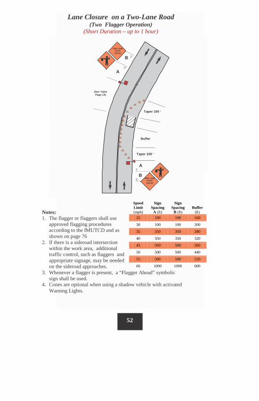
Lane Closure on a Two-Lane Road (Two Flagger Operation)
(Short Duration – up to 1 hour)
A
ONE LANE ROAD
AHEAD
ONE LANE ROAD
AHEAD
(See Table Page 14)
Taper 100 ‘
Buffer
Taper 100 ‘
B
A
Notes: 1. The flagger or flaggers shall use
approved flagging procedures according to the IMUTCD and as shown on page 76
2. If there is a sideroad intersection within the work area, additional traffic control, such as flaggers and appropriate signage, may be needed on the sideroad approaches.
3. Whenever a flagger is present, a “Flagger Ahead” symbolic sign shall be used.
4. Cones are optional when using a shadow vehicle with activated Warning Lights.
Speed Limit (mph)
Sign Spacing
A (ft)
Sign Spacing
B (ft) Buffer
(ft) 25 100 100 160
30 100 100 200
35 350 350 280
40 350 350 320
45 500 500 360
50 500 500 440
55 500 500 520
60 1000 1000 600
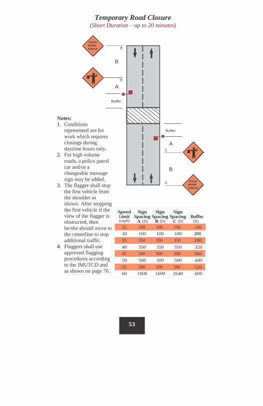
Temporary Road Closure (Short Duration – up to 20 minutes)
ROAD WORK AHEAD
B
A
Buffer
Notes: 1. Conditions
represented are for work which requires closings during daytime hours only.
2. For high volume roads, a police patrol car and/or a changeable message sign may be added.
3. The flagger shall stop the first vehicle from the shoulder as shown. After stopping the first vehicle if the view of the flagger is obstructed, then he/she should move to the centerline to stop additional traffic.
4. Flaggers shall use approved flagging procedures according to the IMUTCD and as shown on page 76.
Buffer
A
B
ROAD WORK AHEAD
Speed Sign Sign Sign Limit Spacing Spacing Spacing Buffer (mph) A (ft) B (ft) C (ft) (ft)
30 100 100 100 200
40 350 350 350 320
50 500 500 500 440
60 1000 1600 2640 600
53
55 500 500 500 520
45 500 500 500 360
35 350 350 350 280
25 100 100 100 160
A
54
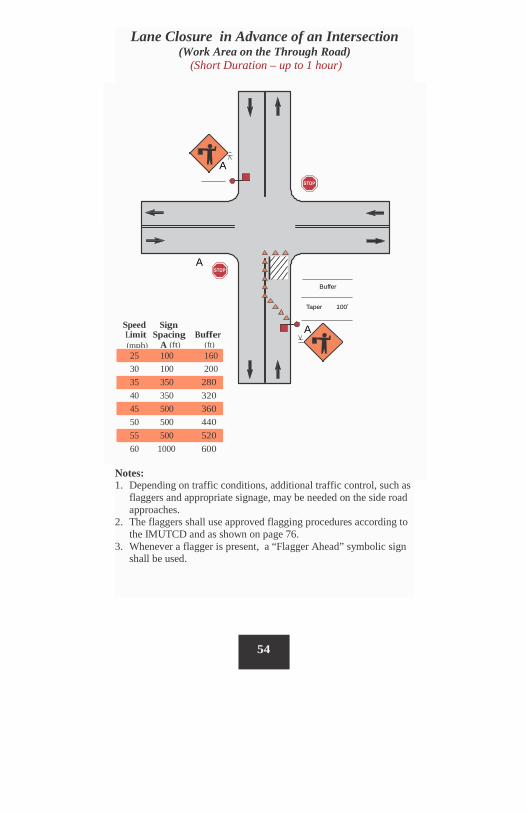
Lane Closure in Advance of an Intersection (Work Area on the Through Road)
(Short Duration – up to 1 hour)
A
A
Buffer
Taper 100ʼ
Speed Sign Limit Spacing Buffer
(mph) A (ft) (ft)
25 100 160 30 100 200 35 350 280 40 350 320 45 500 360 50 500 440 55 500 520 60 1000 600
Notes: 1. Depending on traffic conditions, additional traffic control, such as
flaggers and appropriate signage, may be needed on the side road approaches.
2. The flaggers shall use approved flagging procedures according to the IMUTCD and as shown on page 76.
3. Whenever a flagger is present, a “Flagger Ahead” symbolic sign shall be used.
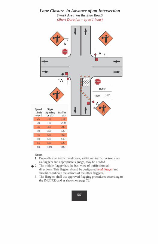
Lane Closure in Advance of an Intersection (Work Area on the Side Road) (Short Duration – up to 1 hour)
A
A
A
Buffer
100ʼ Taper
A
(mph) A (ft) (ft)
Notes: 1. Depending on traffic conditions, additional traffic control, such
as flaggers and appropriate signage, may be needed. 2. The middle flagger has the best view of traffic from all
directions. This flagger should be designated lead flagger and should coordinate the actions of the other flaggers.
3. The flaggers shall use approved flagging procedures according to the IMUTCD and as shown on page 76.
55
Speed Sign Limit Spacing Buffer
25 100 160 30 100 200 35 350 280 40 350 320 45 500 360 50 500 440 55 500 520 60 1000 600
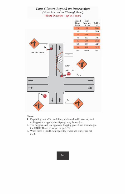
Speed Limit (mph)
Sign Spacing
A (ft) Buffer
(ft)
30 100 200
40 350 320
50 500 440 A
60 1000 600 See Table Page 14
100'
Buffer
Taper 100'
A
A
A
Notes: 1. Depending on traffic conditions, additional traffic control, such
as flaggers and appropriate signage, may be needed. 2. The flaggers shall use approved flagging procedures according to
the IMUTCD and as shown on page 76. 3. When there is insufficient space the Taper and Buffer are not
used.
56
Lane Closure Beyond an Intersection (Work Area on the Through Road)
(Short Duration – up to 1 hour)
25 100 160
35 350 280
45 500 360
55 500 520
Lane Closure Beyond an Intersection (Work Area on the Side Road) (Short Duration – up to 1 hour)
(mph) A (ft) (ft)
A See Table Page 14 100'
Buffer
Taper 100'
A
A
A
Notes: 1. Depending on traffic conditions, additional traffic control, such
as flaggers and appropriate signage, may be needed. 2. The middle flagger should be designated lead flagger and should
coordinate the actions of the other flaggers. 3. The flaggers shall use approved flagging procedures according to
the IMUTCD and as shown on page 76. 4. When there is insufficient space the Taper and Buffer are not
used.
57
Speed Sign Limit Spacing Buffer
25 100 160 30 100 200 35 350 280 40 350 320 45 500 360 50 500 440 55 500 520 60 1000 600
Speed Sign Limit Spacing Buffer (mph) A, B (ft) (ft)
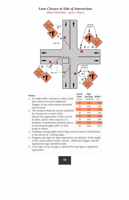
Lane Closure at Side of Intersection (Short Duration – up to 1 hour)
ONE LANE ROAD
AHEAD
(optional) See Note 4 B
A ONE LANE
ROAD AHEAD Taper 100'
A B
(optional) See Note 4 B A
ONE LANE ROAD
AHEAD Taper 100' A
B
ONE LANE ROAD
AHEAD
58
Notes: 1. For high traffic volumes or when a four
lane street is involved additional flaggers or law enforcement personnel may be used.
2. The situation depicted can be simplified by closing one or more of the intersection approaches. If this can not be done, and/or when capacity is a problem, consideration should be given to diverting through traffic to other roads or streets.
3. Flashing warning lights and/or flags may be used to call attention to the advanced warning signs.
4. Flaggers and signs for these approaches are optional. If the length of the closure and/or traffic warrant, additional flaggers and the appropriate signs should be used.
5. Cone taper at top of page is optional for stop sign or signalized approaches.
25 100 160 30 100 200
35 350 280 40 350 320
45 500 360 50 500 440
55 500 520 60 1000 600
Sign Spacing B (ft) 100 350 350 500 500 500
1600
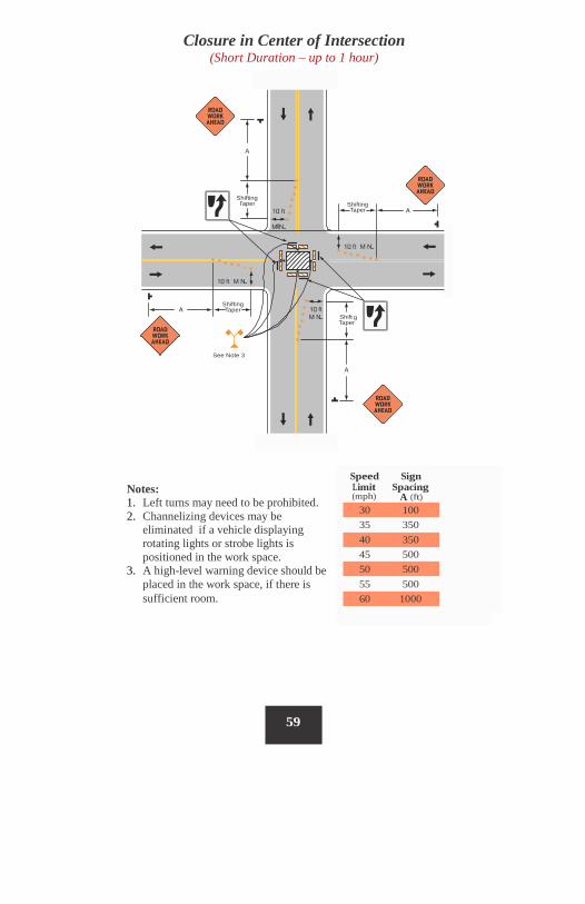
Closure in Center of Intersection (Short Duration – up to 1 hour)
Shifting Shifting
Taper g
Taper
See Note 3
(mph) A (ft)
59
Speed Sign Limit Spacing
30 100 35 350 40 350 45 500 50 500 55 500 60 1000
Shifti
Taper
Shifting
Taper
Notes: 1. Left turns may need to be prohibited. 2. Channelizing devices may be
eliminated if a vehicle displaying rotating lights or strobe lights is positioned in the work space.
3. A high-level warning device should be placed in the work space, if there is sufficient room.
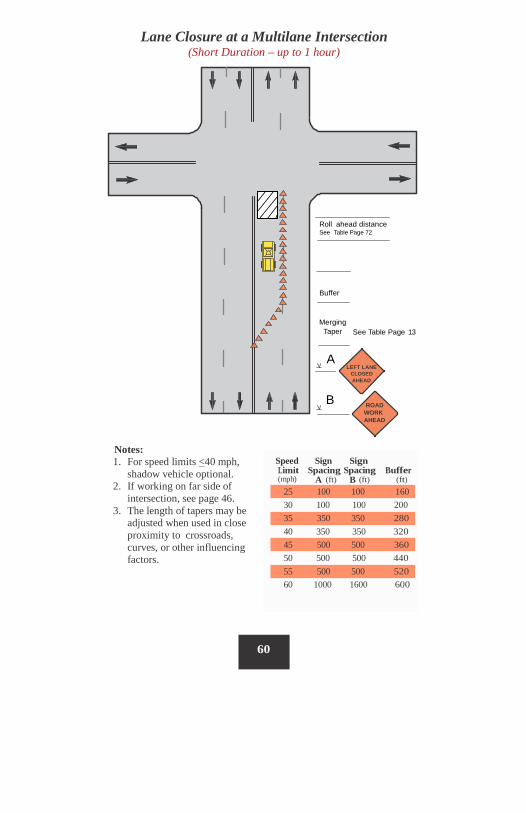
Lane Closure at a Multilane Intersection (Short Duration – up to 1 hour)
Roll ahead distance See Table Page 72
Buffer
Merging Taper See Table Page 13
A LEFT LANE
CLOSED AHEAD
B ROAD WORK AHEAD
60
Speed Sign Sign Limit Spacing Spacing Buffer (mph) A (ft) B (ft) (ft)
25 100 100 160 30 100 100 200 35 350 350 280 40 350 350 320 45 500 500 360 50 500 500 440 55 500 500 520 60 1000 1600 600
Notes: 1. For speed limits <40 mph,
shadow vehicle optional. 2. If working on far side of
intersection, see page 46. 3. The length of tapers may be
adjusted when used in close proximity to crossroads, curves, or other influencing factors.
Turn Lane Closure at an Intersection (Short Duration – up to 1 hour)
Merging Taper
See Table Page 13
A ROAD WORK AHEAD
Notes: 1. Lane may be opened beyond
work area. 2. The length of the tapers may be
adjusted when used in close proximity to crossroads, curves, or other influencing factors.
61
Speed Sign Limit Spacing (mph) A (ft)
25 100 30 100 35 350 40 350 45 500 50 500 55 500 60 1000
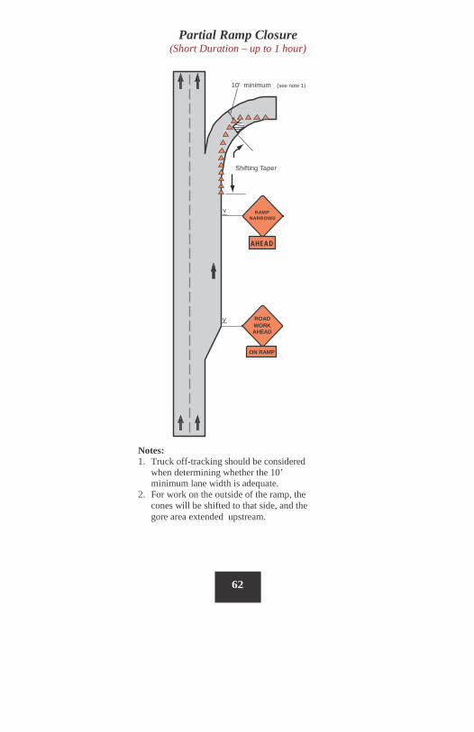
Partial Ramp Closure (Short Duration – up to 1 hour)
10' minimum (see note 1)
Shifting Taper
RAMP NARROWS
AHEAD
ROAD WORK AHEAD
ON RAMP
Notes: 1. Truck off-tracking should be considered
when determining whether the 10’ minimum lane width is adequate.
2. For work on the outside of the ramp, the cones will be shifted to that side, and the gore area extended upstream.
62
Buffer
(ft) 120 170 220 280 335 415 485 580
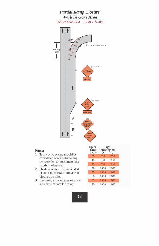
Partial Ramp Closure Work in Gore Area
(Short Duration – up to 1 hour)
10' minimum (see note 1)
Shifting Taper
(see note 3)
RAMP NARROWS
AHEAD
(see note 3) ROAD
WORK AHEAD
ON RAMP
A RIGHT
SHOULDER CLOSED AHEAD
B ROAD
WORK AHEAD
(mph) A B
63
Speed Sign Limit Spacing (ft)
35 350 350 40 350 350 45 500 500 50 1000 1600 55 1000 1600 60 1000 1600 65 1000 1600 70 1000 1600
Notes: 1. Truck off-tracking should be
considered when determining whether the 10’ minimum lane width is adequate.
2. Shadow vehicle recommended inside coned area, if roll ahead distance permits.
3. Required, if coned area or work area extends into the ramp.

Mobile Operations

64
Mobile Operations Mobile operations are work activities that move along the road either intermittently or continuously. Safety for mobile operations should not be compromised by using fewer devices simply because the operation will frequently change its location. Portable devices should be used. For example, appropriately colored and marked vehicles with vehicle warning lights, perhaps augmented with signs or arrow displays, may be used in place of signs and channelizing devices. For mobile operations to be successful, the advance warning area for these operations must move with the work area or be repositioned periodically to provide advanced warning for the motorist. Intermittent Mobile Operations – These mobile operations often involve frequent short stops that are similar to stationary operations. Warning signs, flashing vehicle lights, and/or channelizing devices should be used. With operations that move slowly (less than 3 MPH), it may be feasible to use stationary signing that is periodically retrieved and repositioned in the advance warning area. In addition, vehicles may be equipped with such devices as vehicle warning lights, truck mounted attenuators, and appropriate signs. Flaggers may be used, but caution must be exercised so they are not exposed to unnecessary hazards. Continuously Moving Mobile Operations – These mobile operations include work activities in which workers and equipment move along the road without stopping, (e.g. pavement striping, mowing, street sweeping, or herbicide spraying), usually at slow speeds. For some continuously moving operations where volumes are light and visibility is good, a well-marked and well-signed vehicle may suffice. If volumes and/or speeds are higher, a shadow vehicle, equipped as a sign truck, should follow the work vehicle. The advance warning area moves with the work area. If a lead vehicle is utilized, then an END CONSTRUCTION sign should be used to help identify the end of the work zone.
65
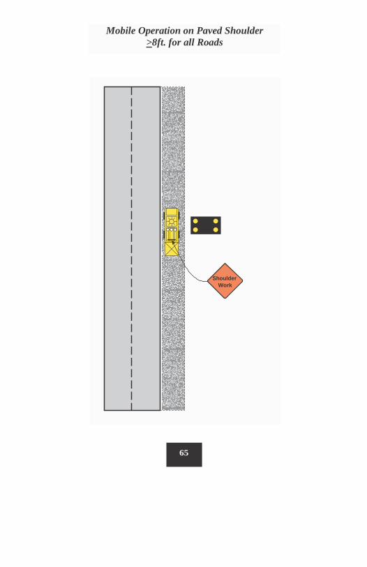
Shoulder Work
Mobile Operation on Paved Shoulder >8ft. for all Roads
Notes: 1. If the operation requires encroachment on the travelway, a mobile
or stationary lane closure should be used. 2. For operations that move slowly (less than 3 mph) and in
situations where multiple work locations in a limited distance make it practical to place stationary signs, the maximum spacing from the advanced warning sign to the beginning of the work is 5 miles.
3. The length of work sign or a supplemental panel (Next XX Miles) may be used for work zones of more than 2 miles in length.
4. If the distance between work locations is one mile or more, and if the work vehicle travels at traffic speeds between locations, warning signs are not required if vehicle warning lights are used.
5. Other acceptable advanced warning signs include SHOULDER WORK, UTILITY WORK AHEAD, MOWING, WORKER SIGNS, and ROAD MACHINERY AHEAD.
6. Table below shows recommended roll-ahead distances between a shadow vehicle with or without a truck mounted attenuator (TMA) and the work area for both stationary and mobile operations.
66
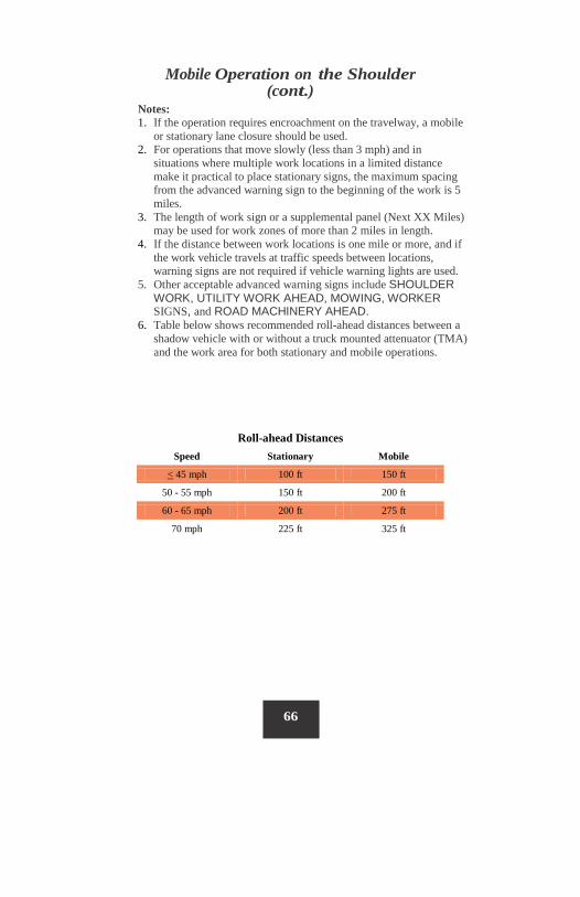
Mobile Operation on the Shoulder (cont.)
Roll-ahead Distances
Speed Stationary Mobile
< 45 mph 100 ft 150 ft
50 - 55 mph 150 ft 200 ft
60 - 65 mph 200 ft 275 ft
70 mph 225 ft 325 ft
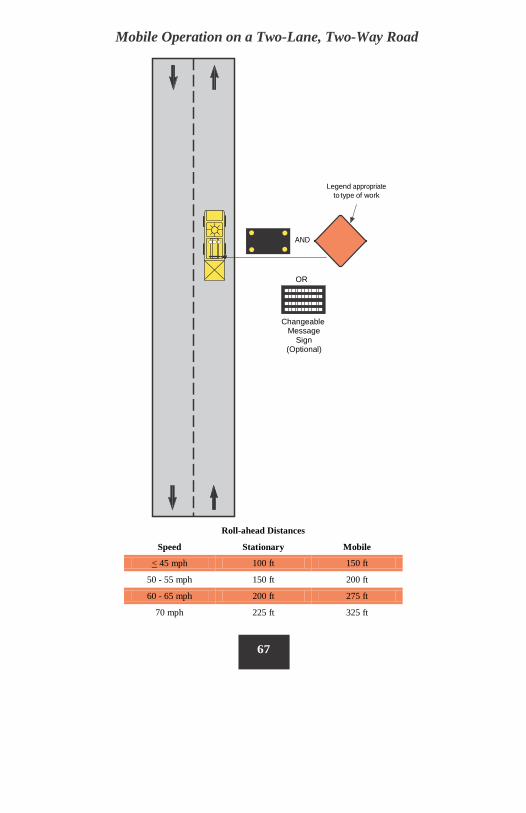
Mobile Operation on a Two-Lane, Two-Way Road
Legend appropriate to type of work
AND
OR
Changeable Message
Sign (Optional)
67
Roll-ahead Distances
Speed Stationary Mobile
< 45 mph 100 ft 150 ft
50 - 55 mph 150 ft 200 ft
60 - 65 mph 200 ft 275 ft
70 mph 225 ft 325 ft
Mobile Operation on a Two-Lane, Two-Way Road (cont.)
Notes: 1. Where practicable and when needed, the work and shadow vehicles
should pull over periodically to allow traffic to pass. If this can not be done frequently, as an alternative, a DO NOT PASS sign may be placed on the rear of the vehicle blocking the lane.
2. Flaggers may be used. If flaggers are used, then a “Flagger Ahead” symbolic sign and a ONE LANE ROAD AHEAD sign shall be used in each direction. If flaggers are used for more than 1 hour, then a ROAD WORK AHEAD sign shall be used as well. Refer to Page 14 for flagger placement.
3. The distance between the work and shadow vehicle may vary according to terrain, paint drying time, and other factors. Shadow vehicles are used to warn traffic of the operation ahead. Whenever adequate stopping sight distance exists to the rear, the shadow vehicle should maintain the minimum roll ahead distance and proceed at the same speed as the work vehicle. The shadow vehicle should slow down in advance of vertical or horizontal curves that restrict sight distance.
4. Sign legends shall be covered or turned from view when work is not in progress.
68
See Note 1
See Note 1
ONE LANE ROAD
AHEAD B
C MIN
(3 MILES MAX)
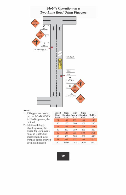
Notes: 1. If flaggers are used <1
hr., the ROAD WORK AHEAD signs may be omitted.
2. Additional flagger ahead signs may be staged for work over 5 miles in length, but shall be turned away from all traffic or layed down until needed
Speed Sign Sign Sign Limit Spacing Spacing Spacing Buffer (mph) A (ft) B (ft) C (ft) (ft)
30 100 100 100 200
40 350 350 350 320
50 500 500 500 440
60 1000 1600 2640 600
69
55 500 500 500 520
45 500 500 500 360
35 350 350 350 280
25 100 100 100 160
ROAD WORK AHEAD
C MIN
(3 MILES MAX)
Mobile Operation on a Two-Lane Road Using Flaggers
A MIN
(1 MILE MAX)
B
A MIN
(1 MILE MAX)
See Table Page 14
Roll Ahead
Buffer
100’
ONE LANE ROAD
AHEAD
ROAD WORK AHEAD
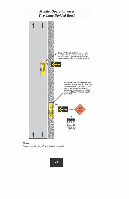
Where adequate shoulder width is not available, Shadow Vehicle 2 shall drive completely in the closed lane. If work zone is on a curbed roadway with inadequate shoulder or a low speed roadway, Shadow Vehicle 2 may be eliminated.
2
RIGHT LANE
CLOSED AHEAD
Notes: See notes #2, #4, #5 and #6 on page 66.
70
Mobile Operation on a Two-Lane Divided Road
1
Shadow Vehicle 1 shall follow in line with the work vehicle. If Shadow Vehicle 2 is not used then a sign with the appropriate legend shall be used on Shadow Vehicle 1
AND
OR
Changeable Message Sign
(Optional)
3
AND
OR
Changeable Message
Sign (Optional)
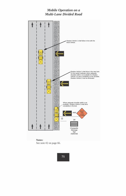
Mobile Operation on a Multi-Lane Divided Road
Notes: See note #2 on page 66.
71
Where adequate shoulder width is not available, Shadow Vehicle 3 shall drive completely in the lane
RIGHT TWO
LANES CLOSED
3
1
Shadow Vehicle 1 shall follow in line with the Work Vehicle.
2
Shadow Vehicle 2 shall drive in the near lane. On low speed roadways where adequate shoulder width is not available for Shadow Vehicle 3 to drive completely on the shoulder, Shadow Vehicle 2 may be eliminated
72
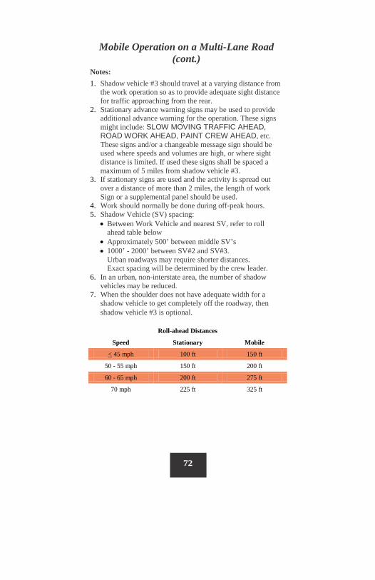
Roll-ahead Distances
Speed Stationary Mobile
< 45 mph 100 ft 150 ft
50 - 55 mph 150 ft 200 ft
60 - 65 mph 200 ft 275 ft
70 mph 225 ft 325 ft
Mobile Operation on a Multi-Lane Road (cont.)
Notes: 1. Shadow vehicle #3 should travel at a varying distance from
the work operation so as to provide adequate sight distance for traffic approaching from the rear.
2. Stationary advance warning signs may be used to provide additional advance warning for the operation. These signs might include: SLOW MOVING TRAFFIC AHEAD, ROAD WORK AHEAD, PAINT CREW AHEAD, etc. These signs and/or a changeable message sign should be used where speeds and volumes are high, or where sight distance is limited. If used these signs shall be spaced a maximum of 5 miles from shadow vehicle #3.
3. If stationary signs are used and the activity is spread out over a distance of more than 2 miles, the length of work Sign or a supplemental panel should be used.
4. Work should normally be done during off-peak hours. 5. Shadow Vehicle (SV) spacing:
• Between Work Vehicle and nearest SV, refer to roll ahead table below
• Approximately 500’ between middle SV’s • 1000’ - 2000’ between SV#2 and SV#3.
Urban roadways may require shorter distances. Exact spacing will be determined by the crew leader.
6. In an urban, non-interstate area, the number of shadow vehicles may be reduced.
7. When the shoulder does not have adequate width for a shadow vehicle to get completely off the roadway, then shadow vehicle #3 is optional.
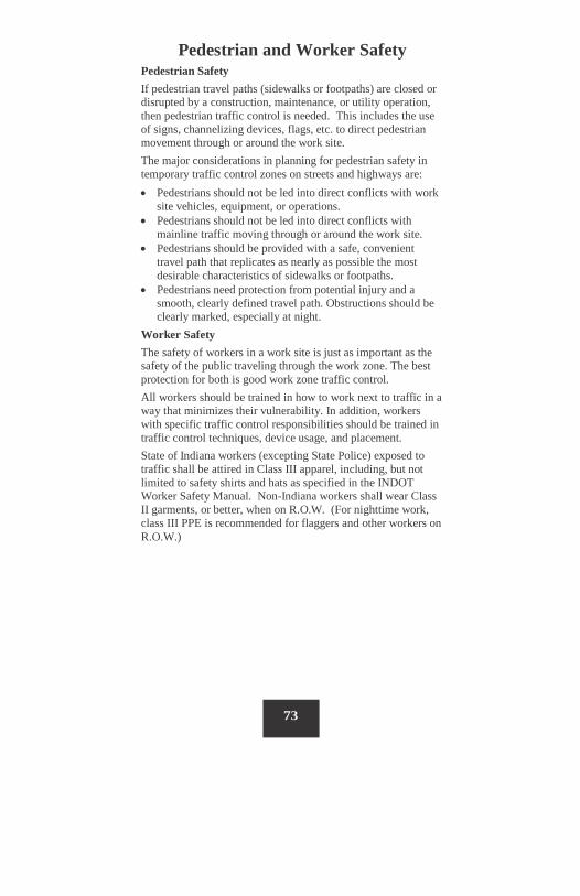
Pedestrian and Worker Safety Pedestrian Safety If pedestrian travel paths (sidewalks or footpaths) are closed or disrupted by a construction, maintenance, or utility operation, then pedestrian traffic control is needed. This includes the use of signs, channelizing devices, flags, etc. to direct pedestrian movement through or around the work site. The major considerations in planning for pedestrian safety in temporary traffic control zones on streets and highways are: • Pedestrians should not be led into direct conflicts with work
site vehicles, equipment, or operations. • Pedestrians should not be led into direct conflicts with
mainline traffic moving through or around the work site. • Pedestrians should be provided with a safe, convenient
travel path that replicates as nearly as possible the most desirable characteristics of sidewalks or footpaths.
• Pedestrians need protection from potential injury and a smooth, clearly defined travel path. Obstructions should be clearly marked, especially at night.
Worker Safety The safety of workers in a work site is just as important as the safety of the public traveling through the work zone. The best protection for both is good work zone traffic control. All workers should be trained in how to work next to traffic in a way that minimizes their vulnerability. In addition, workers with specific traffic control responsibilities should be trained in traffic control techniques, device usage, and placement. State of Indiana workers (excepting State Police) exposed to traffic shall be attired in Class III apparel, including, but not limited to safety shirts and hats as specified in the INDOT Worker Safety Manual. Non-Indiana workers shall wear Class II garments, or better, when on R.O.W. (For nighttime work, class III PPE is recommended for flaggers and other workers on R.O.W.)
73
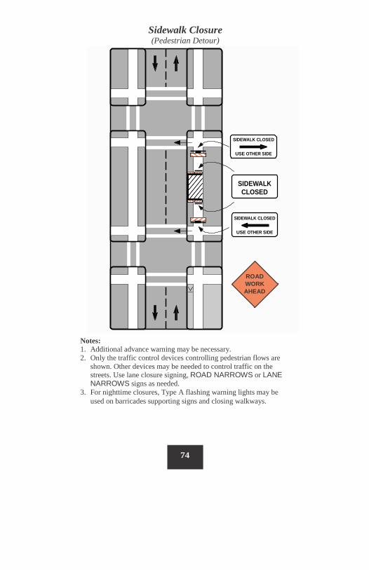
Sidewalk Closure (Pedestrian Detour)
Notes: 1. Additional advance warning may be necessary. 2. Only the traffic control devices controlling pedestrian flows are
shown. Other devices may be needed to control traffic on the streets. Use lane closure signing, ROAD NARROWS or LANE NARROWS signs as needed.
3. For nighttime closures, Type A flashing warning lights may be used on barricades supporting signs and closing walkways.
74
SIDEWALK CLOSED
USE OTHER SIDE
SIDEWALK CLOSED
SIDEWALK CLOSED
USE OTHER SIDE
ROAD WORK AHEAD
75
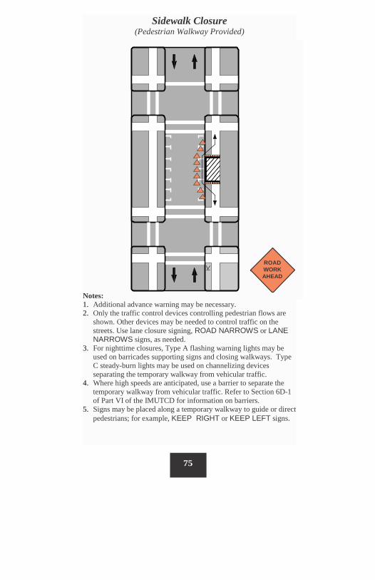
Sidewalk Closure (Pedestrian Walkway Provided)
ROAD WORK AHEAD
Notes: 1. Additional advance warning may be necessary. 2. Only the traffic control devices controlling pedestrian flows are
shown. Other devices may be needed to control traffic on the streets. Use lane closure signing, ROAD NARROWS or LANE NARROWS signs, as needed.
3. For nighttime closures, Type A flashing warning lights may be used on barricades supporting signs and closing walkways. Type C steady-burn lights may be used on channelizing devices separating the temporary walkway from vehicular traffic.
4. Where high speeds are anticipated, use a barrier to separate the temporary walkway from vehicular traffic. Refer to Section 6D-1 of Part VI of the IMUTCD for information on barriers.
5. Signs may be placed along a temporary walkway to guide or direct pedestrians; for example, KEEP RIGHT or KEEP LEFT signs.
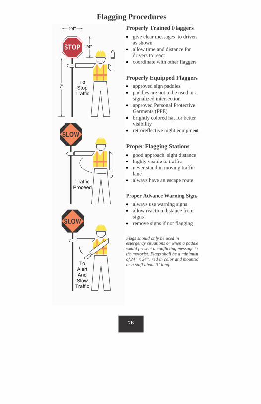
Flagging Procedures
76
Properly Trained Flaggers • give clear messages to drivers
as shown • allow time and distance for
drivers to react • coordinate with other flaggers
Properly Equipped Flaggers • approved sign paddles • paddles are not to be used in a
signalized intersection • approved Personal Protective
Garments (PPE) • brightly colored hat for better
visibility • retroreflective night equipment
Proper Flagging Stations • good approach sight distance • highly visible to traffic • never stand in moving traffic
lane • always have an escape route
Proper Advance Warning Signs • always use warning signs • allow reaction distance from
signs • remove signs if not flagging
Flags should only be used in emergency situations or when a paddle would present a conflicting message to the motorist. Flags shall be a minimum of 24” x 24”, red in color and mounted on a staff about 3’ long.
To Stop
Traffic
7’
24"
24"
Traffic Proceed
To Alert And Slow
Traffic
Quick Reference Guide
77
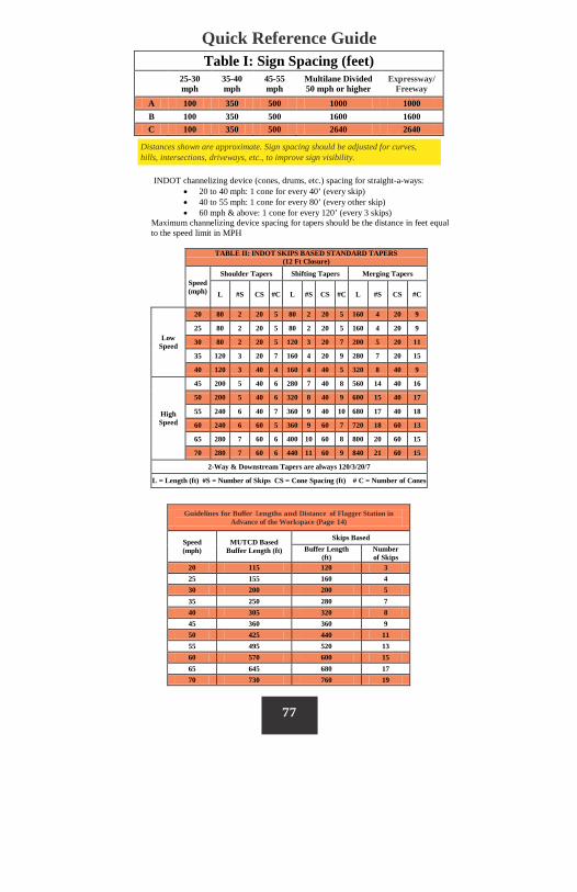
Distances shown are approximate. Sign spacing should be adjusted for curves, hills, intersections, driveways, etc., to improve sign visibility.
INDOT channelizing device (cones, drums, etc.) spacing for straight-a-ways: • 20 to 40 mph: 1 cone for every 40’ (every skip) • 40 to 55 mph: 1 cone for every 80’ (every other skip) • 60 mph & above: 1 cone for every 120’ (every 3 skips)
Maximum channelizing device spacing for tapers should be the distance in feet equal to the speed limit in MPH
Table I: Sign Spacing (feet)
25-30 mph
35-40 mph
45-55 mph
Multilane Divided 50 mph or higher
Expressway/ Freeway
A 100 350 500 1000 1000 B 100 350 500 1600 1600 C 100 350 500 2640 2640
TABLE II: INDOT SKIPS BASED STANDARD TAPERS (12 Ft Closure)
Speed (mph)
Shoulder Tapers Shifting Tapers Merging Tapers
L #S CS #C L #S CS #C L #S CS #C
Low Speed
20 80 2 20 5 80 2 20 5 160 4 20 9
25 80 2 20 5 80 2 20 5 160 4 20 9
30 80 2 20 5 120 3 20 7 200 5 20 11
35 120 3 20 7 160 4 20 9 280 7 20 15
40 120 3 40 4 160 4 40 5 320 8 40 9
High Speed
45 200 5 40 6 280 7 40 8 560 14 40 16
50 200 5 40 6 320 8 40 9 600 15 40 17
55 240 6 40 7 360 9 40 10 680 17 40 18
60 240 6 60 5 360 9 60 7 720 18 60 13
65 280 7 60 6 400 10 60 8 800 20 60 15
70 280 7 60 6 440 11 60 9 840 21 60 15
2-Way & Downstream Tapers are always 120/3/20/7
L = Length (ft) #S = Number of Skips CS = Cone Spacing (ft) # C = Number of Cones
Guidelines for Buffer Lengths and Distance of Flagger Station in Advance of the Workspace (Page 14)
Speed (mph)
MUTCD Based Buffer Length (ft)
Skips Based Buffer Length
(ft) Number of Skips
20 115 120 3 25 155 160 4 30 200 200 5 35 250 280 7 40 305 320 8 45 360 360 9 50 425 440 11 55 495 520 13 60 570 600 15 65 645 680 17 70 730 760 19

I N D O T
Indiana Department of Transportation Work Zone Safety Section 120 South Shortridge Road
Indianapolis, IN 46219 Phone: 317-610-7251 ext. 304
Fax 317-356-9351 www.workzonesafety.in.gov