table of contents - maintenance manual
TRANSCRIPT
Service Department (800) 888-7009
Table of Contents
Assembly Instructions …………………………………………………………… 1
Assembly Figure …………………………………………………………………. 4
Maintenance Instructions ……………………………………………………….. 5Daily ………………………………………………………………………. 5Weekly …………………………………………………………………….. 5
Lubricating the Chain ……………………………………………... 5Check Friction Belt ………………………………………………... 6Clean Bike ………………………………………………………….6
Monthly ……………………………………………………….…………... 6Chain Guard Check ………………………………………….……. 6Wax the Bike ……………………………………………….……... 6Clean the Chain …………………………………………………… 6Check Chain Tension ………………………………………………7Check Bottom Bracket & Crank Arms ……………………………. 7Check Shifter Cable Assembly ……………………………………. 8Check Flywheel Adjustment ……………………………………… 8Clean and Lubricate Flywheel Groove ……………………………. 9Lubricate Shift Lever ……………………………………………… 10Lubricate Handle Bar Clamp Handle Threads ……………………..10
Adjustments ………………………………………………………………….……11User Adjustments ……………………………….………………………….11Maintenance Adjustments ………………………………………………….14
Removal of Chain Cover ………………………………………….. 14Chain Tension & Flywheel Adjustment …………………………... 15Friction Belt Adjustment ………………………………………….. 17Shift Lever Tension ……………………………………………….. 19Seat (Non-adjustable) …………………………………………..…. 19Replacement of Friction Belt………………………………………. 19
Bottom Bracket Installation …………………………………………………….. 21
Torque Specifications ……………………………………………...……… 22Tools ….…………………………………………………………………… 22
Trouble Shooting ………………………………………………………………… 23
Parts List……..…………………………………………………………………… 24
Exploded Detail Diagram ………………………………………………….…….. 25
Service Department (800) 888-7009
INTRODUCTION
KEISER CORPORATION has always taken pride in designing and engineering the highestquality equipment on the market. This means that you will receive years of low maintenanceand minimal repairs from every one of our machines. Only the highest quality products have theKEISER name on them.
This manual was written with the customer in mind. It will assist you in the unlikely event thatour KEISER Power Pacer or Free Wheel develops any type of problems. This manual coverseverything from daily maintenance to replacements of any worn parts. In essence, any problemsthat may develop are addressed in this manual.
This manual provides a detail breakdown of all of the KEISER Power Pacer/ Free Wheel, with afull list of part numbers at time of publication. Since we always find ways to improve ourproducts, parts and machine designs are subject to change without notice. If you have anyquestion, please call our service department at (800) 888-7009.
WORD DEFINITIONS
SAFETY CAUTIONS and WARNINGS:We've put a number of safety cautions in this book. We use the word Caution! to tell you aboutthings that could cause bodily injury to persons on or around the equipment if you were to ignorethe following instructions and the word Warning! to ensure the proper installation ofcomponents and that the instructions are followed for the safety of the users and for maximummachine life or the warranty is void.
HINTS:We use the word Note! in this book to tell you about things that we recommend you doing orthings to be aware of before performing the instructions. These notes were placed in the manualto aid you during a certain procedure.
Warning!
Failure to follow the assembly or operation instructions as provided by thismanual or any other instructions pertaining to the assembly and/or operation ofKEISER equipment will result in voiding the warranty and could lead to serious
injury.
Service Department (800) 888-70091
ASSEMBLY INSTRUCTIONS
Tools Required: 1/2 inch socket Paste Wax (not included)1/2 inch wrench Ex. Turtle Wax (Paste type)9/16 inch wrench Crescent wrench15mm socket Torque wrenchSmall #1 Phillips screw driver 15mm Crows Foot
Caution!The unit should only be operated with the chain cover guard fitted correctly, as supplied.Children in the area and users are vulnerable to injuries to fingers if the unit is used withoutthe chain cover guard. Refer to Monthly Maintenance section A. on chain lubrication andcover checking.
A. UnpackTools Required: 1/2 inch socket or wrench
1. Remove the bike and the following loose parts from the packing box :
a) Handlebar Assemblyb) Front and Rear Footc) Pedalsd) Set of 4 Bolts, Nuts and Washers for Feete) Seat (Adjustable Seat Post option only)f) Handle Bar Slugg) Loctite 242 (supplied)
B. WaxingTools Required: Paste wax and a Clean cloth
1. Prior to assembling the frame and feet assembly, a coat of paste wax
must be applied. This will help protect the powder coat paint on the frame and feet.
2. Apply the wax in accordance to the wax manufacture’s procedures.
Warning! Failure to apply wax as instructed will decrease paint and frame life due to sweat and the
warranty will be void.C. Feet (see Figure 2)
Tools Required: 1/2 inch wrench, 1/2 inch deep well socket and torque wrench
1. Remove the round black plugs from the access holes near the center of the feet and setthem aside.
2. Attach the front (with casters) and rear feet to the frame using the 5/16” x 3/4” long bolts, flatwashers (under the head of the bolt) and lock nuts. The bolts should be torqued to 15 ft-lb.
3. Reinsert the black plugs
Service Department (800) 888-70092
D. Pedals (see Figure 2) Tools required: 15 mm wrench (narrow) or pedal spanner, Loctite 242 (supplied),
15mm crows foot, torque wrench
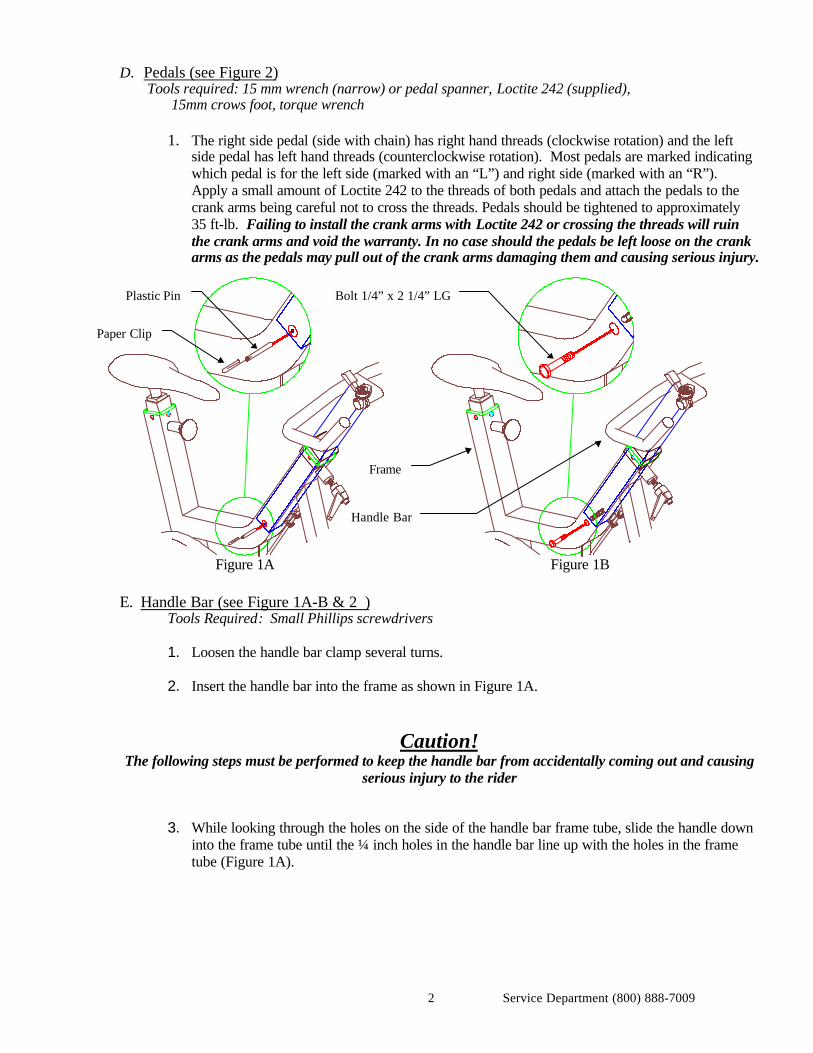
1. The right side pedal (side with chain) has right hand threads (clockwise rotation) and the leftside pedal has left hand threads (counterclockwise rotation). Most pedals are marked indicatingwhich pedal is for the left side (marked with an “L”) and right side (marked with an “R”).Apply a small amount of Loctite 242 to the threads of both pedals and attach the pedals to thecrank arms being careful not to cross the threads. Pedals should be tightened to approximately35 ft-lb. Failing to install the crank arms with Loctite 242 or crossing the threads will ruinthe crank arms and void the warranty. In no case should the pedals be left loose on the crankarms as the pedals may pull out of the crank arms damaging them and causing serious injury.
Figure 1A Figure 1B
E. Handle Bar (see Figure 1A-B & 2 )Tools Required: Small Phillips screwdrivers
1. Loosen the handle bar clamp several turns. 2. Insert the handle bar into the frame as shown in Figure 1A.
Caution!The following steps must be performed to keep the handle bar from accidentally coming out and causing
serious injury to the rider
3. While looking through the holes on the side of the handle bar frame tube, slide the handle downinto the frame tube until the ¼ inch holes in the handle bar line up with the holes in the frametube (Figure 1A).
Plastic Pin
Paper Clip
Bolt 1/4” x 2 1/4” LG
Frame
Handle Bar
Service Department (800) 888-70093
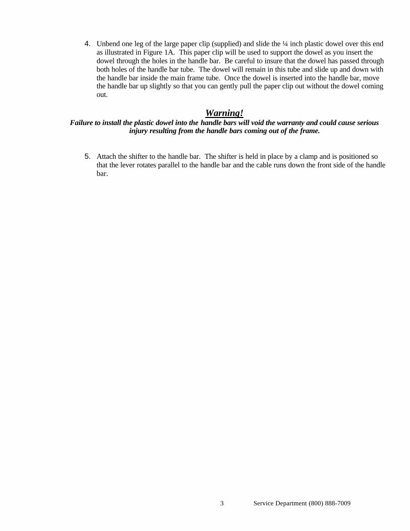
4. Unbend one leg of the large paper clip (supplied) and slide the ¼ inch plastic dowel over this endas illustrated in Figure 1A. This paper clip will be used to support the dowel as you insert thedowel through the holes in the handle bar. Be careful to insure that the dowel has passed throughboth holes of the handle bar tube. The dowel will remain in this tube and slide up and down withthe handle bar inside the main frame tube. Once the dowel is inserted into the handle bar, movethe handle bar up slightly so that you can gently pull the paper clip out without the dowel comingout.
Warning!Failure to install the plastic dowel into the handle bars will void the warranty and could cause serious
injury resulting from the handle bars coming out of the frame.
5. Attach the shifter to the handle bar. The shifter is held in place by a clamp and is positioned sothat the lever rotates parallel to the handle bar and the cable runs down the front side of the handlebar.
Service Department (800) 888-70094
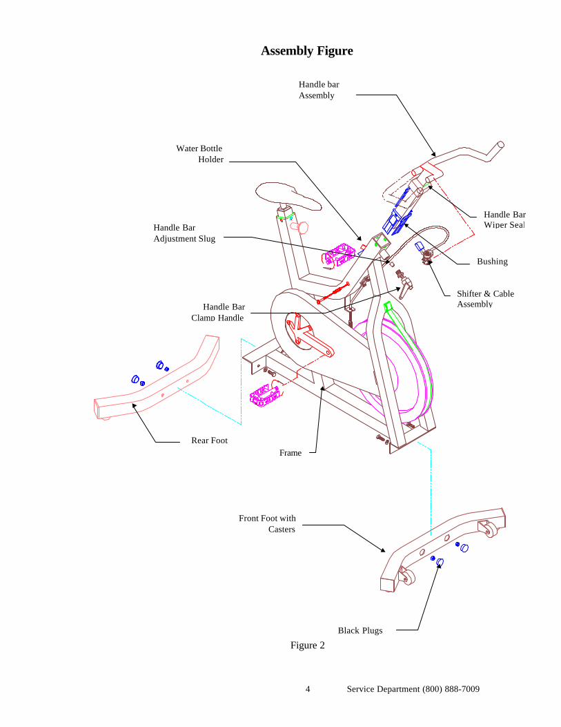
Assembly Figure
Figure 2
Bushing
Shifter & CableAssemblyHandle Bar
Clamp Handle
Front Foot withCasters
Handle barAssembly
Black Plugs
Handle BarAdjustment Slug
Rear Foot
Water BottleHolder
Frame
Handle BarWiper Seal
Service Department (800) 888-70095
MAINTENANCE
Tools Required: “BEL RAY” Chain Lube with Molyphos AdditiveTape Measure 9/16 wrenchClean Cloth 9/16 socket
Mild Soap Chrome Polish Small #1 Phillips screw driver Paste Wax (not included)
Standard #2 Screw Driver Ex. Turtle Wax (Paste type)Bottom Bracket socket
DAILY
• Wipe down the entire bike after every workout with a clean dry cloth.
Caution!The unit should only be operated with the chain cover guard fitted correctly, as supplied. Children in the area and
users are vulnerable to injuries to fingers if the unit is used without the chain cover guard. Refer to MonthlyMaintenance section A. on chain guard cover checking.
WEEKLY
A. Lubricating the ChainTools Required: - “Bel Ray chain lube with Molyphos Additive” is recommended
This lubricant is initially foam that quickly begins to become a fluid, which drips off the chain.
a) Remove the chain cover guard using a flat head screwdriver to pop out the four plastic rivets on the cover.
b) After removing the chain guard, place it under the chain to catch any excess lubrication.
c) Slowly rotate the flywheel by turning the pedal with one hand, while spraying the lubricant on the inside ofthe chain, into the gaps of the chain. Rotate the flywheel until the entire chain has been lubricated.
d) Take a cloth and wipe out the excess lubricant from inside the chain case. Wipe out the inside of the chain
guard, which was used to catch excess lubricant.
e) Replace chain cover guard and pop in the plastic rivets.
B. Check Friction BeltTools Required: None
1. To loosen belt completely, remove all tension on the belt by placing the shift lever on the handlebars to the lowest setting (full clockwise rotation).
2. Inspect both sides of the Friction Belt for excessive wear. If the best has been worn through, the
belt needs to be replaced. See instructions under “Replacement of Friction Belt.”
Service Department (800) 888-70096
C. Clean BikeTools Required: Clean Cloth, Spray on Wax/Cleaner-“Turtle Wax, Wax/Cleaner” is Recommended.
1. Spray the bike with a spray on wax/cleaner and wipe down the seat, handle bars, chain cover andbike frame.
2. Thoroughly wipe down the frame with a clean cloth.
MONTHLY
A. Chain Guard checkTools Required: None
1. Visually check the chain guard for any breaks or cracks. 2. Make sure chain guard is securely fastened to the unit.
B. Wax the Bike (The purpose of applying wax regularly is to prevent rust caused by sweat.)
Tools required: Clean Cloth, Warm Mild Soap & Water, Paste Wax & Chrome Polish
Warning!Failure to apply a coat of paste wax at least once a month as instructed below will decrease paint and frame
life due to sweat and the warranty will be void.
1. Wipe down the seat, handle bars and chain cover with a mild soap and water solution.
2. Thoroughly dry the frame with a clean cloth.
3. Apply wax to the seat (this will help seal the surface) and bike frame in accordance to wax
manufacture’s procedures.
4. Apply the chrome polish to the seat post tube and handle bar tube.
C. Clean the ChainTools Required: Screw Driver, Clean Cloth
Caution!
Extreme care must be taken not to allow your fingers, clothes, hair, etc. to be drawn into the chainand sprockets. This will cause severe injury.
1. Keeping the chain clean will help to extend the life of the chain and drive components. 2. Remove the chain cover following the direction under “Removal of Chain Cover”.
3. While rotating the chain very slowly hold the clean cloth over the chain removing any loose dirt orforeign material from the chain.
4. Once the chain is clean, lubricate the chain as instructed under “Lubrication of Chain”. 5. Replace the chain cover.
Service Department (800) 888-70097
C. Check Chain Tension
Tools Required: Tape measure
Caution!Extreme care must be taken not to allow your fingers to be drawn into the chain and sprockets.
This will cause severe injury.
1. Maintaining proper chain tension will help to extend the life of the chain and drive components.We recommend that the chain be checked at the same time it is cleaned. Removing the chain coveris necessary to check and clean the chain, follow the instructions under “Removal of Chain Cover”.
2. Set the shift lever at the full load position (counter clockwise, Figure 10). Gently move the crank
arm back and forth being careful not to rotate the flywheel. The movement of the end of the crankarm (at the pedal) should not be more than 1/8 of an inch. If the movement of the arm is greaterthan 1/8 of an inch the chain may be out of adjustment.
3. If the chain is out of adjustment, adjust the chain using the instructions under the section “Chain
Tension & Flywheel ” adjustment. 4. If the chain is properly adjusted and still makes noise the chain may be worn or one of the chain
sprockets may be worn and in need of replacement.
D. Check Bottom Bracket & Crank ArmsTools Required: Torque wrench and Bottom Bracket socket
1. Monthly re-torque the crank arm bolts to 35 ft-lbs.. 2. Check to see if the bottom bracket is loose by wiggling crank arms back and forth.
3. If the bottom bracket is loose in the frame re-torque to 57 ft-lbs.
4. If the bottom bracket spindle appears to move within the bottom bracket bearing, then the bottombracket may be worn out and needs replacement. To replace bottom bracket see page 24 andfollow instructions.
Service Department (800) 888-70098
E. Check Shifter Cable AssemblyTools Required: None
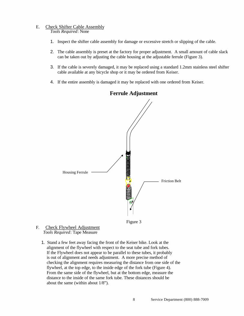
1. Inspect the shifter cable assembly for damage or excessive stretch or slipping of the cable. 2. The cable assembly is preset at the factory for proper adjustment. A small amount of cable slack
can be taken out by adjusting the cable housing at the adjustable ferrule (Figure 3).
3. If the cable is severely damaged, it may be replaced using a standard 1.2mm stainless steel shiftercable available at any bicycle shop or it may be ordered from Keiser.
4. If the entire assembly is damaged it may be replaced with one ordered from Keiser.
Ferrule Adjustment
Figure 3
F. Check Flywheel Adjustment Tools Required: Tape Measure
1. Stand a few feet away facing the front of the Keiser bike. Look at the alignment of the flywheel with respect to the seat tube and fork tubes. If the Flywheel does not appear to be parallel to these tubes, it probably is out of alignment and needs adjustment. A more precise method of checking the alignment requires measuring the distance from one side of the flywheel, at the top edge, to the inside edge of the fork tube (Figure 4). From the same side of the flywheel, but at the bottom edge, measure the distance to the inside of the same fork tube. These distances should be about the same (within about 1/8”).
Housing Ferrule
Friction Belt
Service Department (800) 888-70099
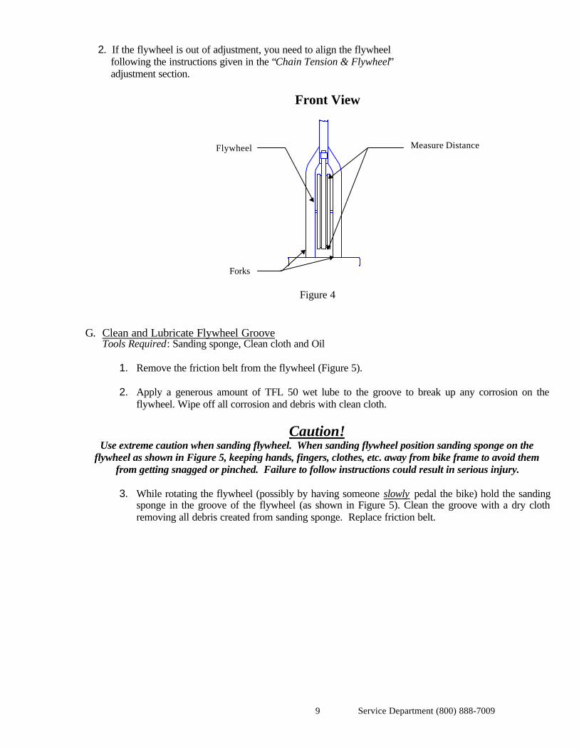
2. If the flywheel is out of adjustment, you need to align the flywheel following the instructions given in the “Chain Tension & Flywheel” adjustment section.
Front View
Figure 4
G. Clean and Lubricate Flywheel Groove Tools Required: Sanding sponge, Clean cloth and Oil
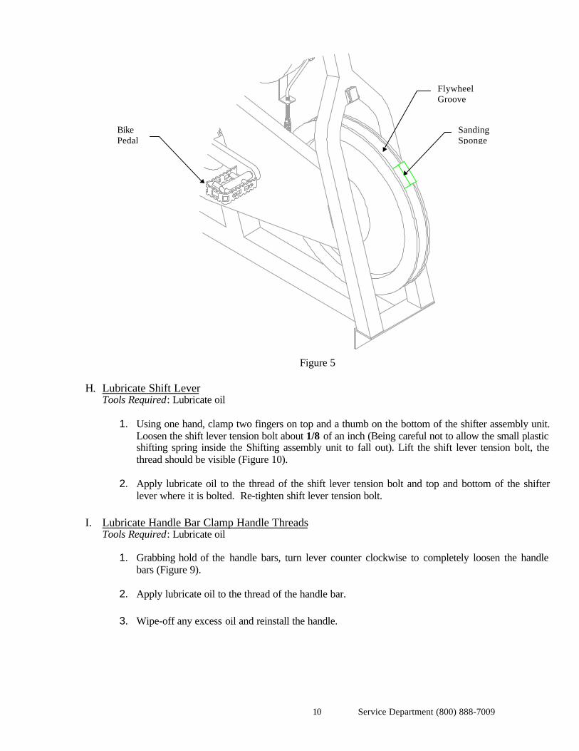
1. Remove the friction belt from the flywheel (Figure 5). 2. Apply a generous amount of TFL 50 wet lube to the groove to break up any corrosion on the
flywheel. Wipe off all corrosion and debris with clean cloth.
Caution!Use extreme caution when sanding flywheel. When sanding flywheel position sanding sponge on the
flywheel as shown in Figure 5, keeping hands, fingers, clothes, etc. away from bike frame to avoid themfrom getting snagged or pinched. Failure to follow instructions could result in serious injury.
3. While rotating the flywheel (possibly by having someone slowly pedal the bike) hold the sandingsponge in the groove of the flywheel (as shown in Figure 5). Clean the groove with a dry clothremoving all debris created from sanding sponge. Replace friction belt.
Measure DistanceFlywheel
Forks
Service Department (800) 888-700910
Figure 5
H. Lubricate Shift Lever Tools Required: Lubricate oil
1. Using one hand, clamp two fingers on top and a thumb on the bottom of the shifter assembly unit.Loosen the shift lever tension bolt about 1/8 of an inch (Being careful not to allow the small plasticshifting spring inside the Shifting assembly unit to fall out). Lift the shift lever tension bolt, thethread should be visible (Figure 10).
2. Apply lubricate oil to the thread of the shift lever tension bolt and top and bottom of the shifter
lever where it is bolted. Re-tighten shift lever tension bolt.
I. Lubricate Handle Bar Clamp Handle Threads Tools Required: Lubricate oil
1. Grabbing hold of the handle bars, turn lever counter clockwise to completely loosen the handlebars (Figure 9).
2. Apply lubricate oil to the thread of the handle bar. 3. Wipe-off any excess oil and reinstall the handle.
FlywheelGroove
BikePedal
SandingSponge
Service Department (800) 888-700911
ADJUSTMENTS
The following section of this manual will consist of two sections. The first section will include all adjustmentsthat can be done by the club member (user). The second section will include all maintenance adjustments thatshould be done by a qualified club maintenance person.
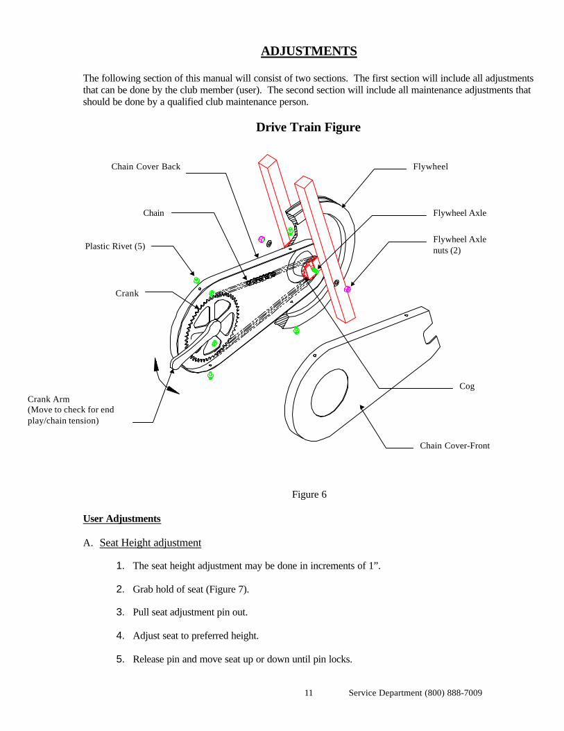
Drive Train Figure
Figure 6
User Adjustments
A. Seat Height adjustment
1. The seat height adjustment may be done in increments of 1”.
2. Grab hold of seat (Figure 7).
3. Pull seat adjustment pin out.
4. Adjust seat to preferred height.
5. Release pin and move seat up or down until pin locks.
Chain Cover Back
Chain
Plastic Rivet (5)
Crank
Chain Cover-Front
Cog
Flywheel Axlenuts (2)
Flywheel Axle
Flywheel
Crank Arm(Move to check for endplay/chain tension)
Service Department (800) 888-700912
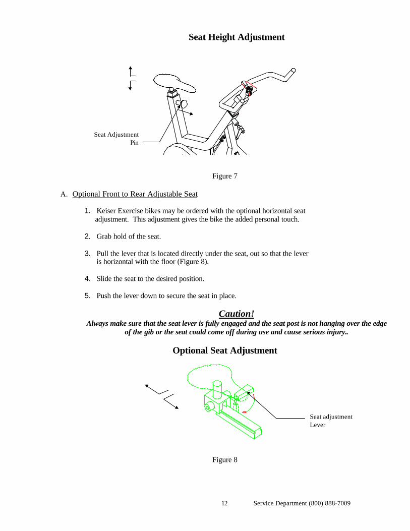
Seat Height Adjustment
Figure 7
A. Optional Front to Rear Adjustable Seat
1. Keiser Exercise bikes may be ordered with the optional horizontal seat adjustment. This adjustment gives the bike the added personal touch.
2. Grab hold of the seat.
3. Pull the lever that is located directly under the seat, out so that the lever is horizontal with the floor (Figure 8).
4. Slide the seat to the desired position.
5. Push the lever down to secure the seat in place.
Caution!Always make sure that the seat lever is fully engaged and the seat post is not hanging over the edge
of the gib or the seat could come off during use and cause serious injury..
Optional Seat Adjustment
Figure 8
Seat AdjustmentPin
Seat adjustmentLever
Service Department (800) 888-700913
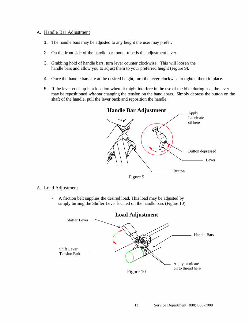
A. Handle Bar Adjustment
1. The handle bars may be adjusted to any height the user may prefer. 2. On the front side of the handle bar mount tube is the adjustment lever. 3. Grabbing hold of handle bars, turn lever counter clockwise. This will loosen the
handle bars and allow you to adjust them to your preferred height (Figure 9). 4. Once the handle bars are at the desired height, turn the lever clockwise to tighten them in place. 5. If the lever ends up in a location where it might interfere in the use of the bike during use, the lever
may be repositioned without changing the tension on the handlebars. Simply depress the button on theshaft of the handle, pull the lever back and reposition the handle.
Handle Bar Adjustment
Figure 9
A. Load Adjustment
• A friction belt supplies the desired load. This load may be adjusted by simply turning the Shifter Lever located on the handle bars (Figure 10).
Load Adjustment
Figure 10
Button
Button depressed
Shifter Lever
Handle Bars
Lever
Shift LeverTension Bolt
ApplyLubricateoil here
Apply lubricateoil to thread here
Service Department (800) 888-700914
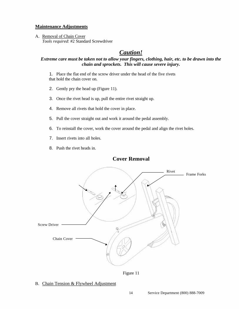
Maintenance Adjustments
A. Removal of Chain Cover Tools required: #2 Standard Screwdriver
Caution!Extreme care must be taken not to allow your fingers, clothing, hair, etc. to be drawn into the
chain and sprockets. This will cause severe injury.
1. Place the flat end of the screw driver under the head of the five rivets that hold the chain cover on.
2. Gently pry the head up (Figure 11).
3. Once the rivet head is up, pull the entire rivet straight up.
4. Remove all rivets that hold the cover in place.
5. Pull the cover straight out and work it around the pedal assembly.
6. To reinstall the cover, work the cover around the pedal and align the rivet holes.
7. Insert rivets into all holes.
8. Push the rivet heads in.
Cover Removal
Figure 11
B. Chain Tension & Flywheel Adjustment
Rivet
Chain Cover
Screw Driver
Frame Forks
Service Department (800) 888-700915
Tools required: 9/16” wrench or socketTape measureChain adjustment tool.Torque Wrench
Caution!Extreme care must be taken to not allow your fingers, hair, clothes, etc. to drawn into the chain
and sprockets. This will cause severe injury.
1. Maintaining proper chain tension will help to extend the life of the chain and drive components. Itis recommended that the chain be checked at the same time it is cleaned. You will need to removethe chain cover, follow the instructions under “Removal of Chain Cover”.
2. Set the shift lever at the full load position, counter clockwise (Figure 10), gently move the crankarm back and forth being careful not to rotate the flywheel. The movement of the end of the crankarm (at the pedal) should not be more than 1/8 of an inch. If the movement of the arm is greaterthan 1/8 of an inch the chain may be out of adjustment.
3. To more precisely check the tension follow the instructions below:
a) Remove the chain cover following instructions under “Removal of Chain Cover”.
b) Slowly rotate the pedals checking the tension of the chain throughout its rotation. Find the position of thechain where it appears to be the tightest.
c) Measure the distance between the chain and the chain cover being careful not to deflect the chain
d) Now push the chain upward with the tape measure until the chain will no longer move. The distance thatthe chain moves should be less than 1/8 of an inch.
4. If the chain is out of adjustment, loosen the flywheel axle nuts (using 9/16 wrench or socket)
allowing flywheel to move to lower position. (Note that each nut may be moved independentlyeliminating the need for 2 wrenches.) This will allow the chain to reach full tension.
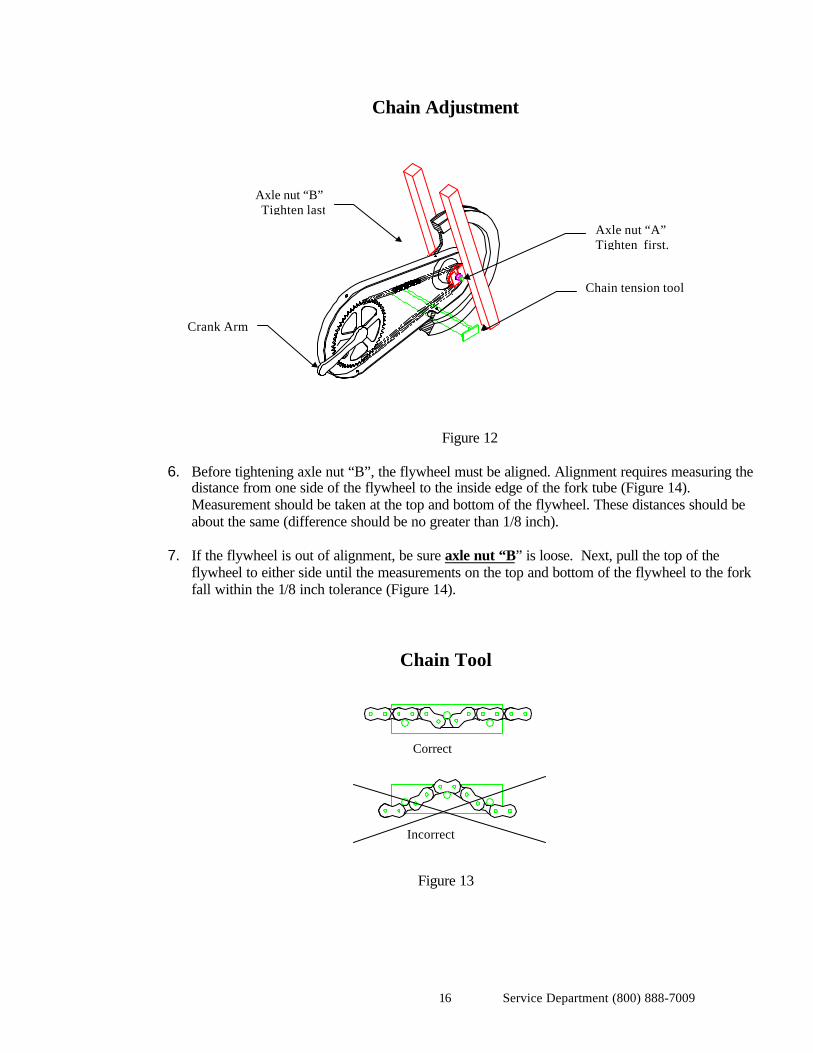
Note! Make sure the tool is not inserted up side down. Refer to Figure 13.
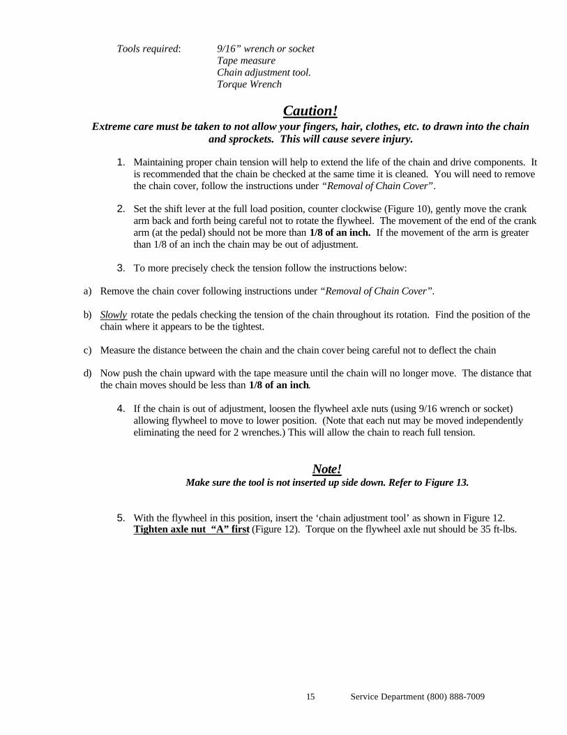
5. With the flywheel in this position, insert the ‘chain adjustment tool’ as shown in Figure 12.
Tighten axle nut “A” first (Figure 12). Torque on the flywheel axle nut should be 35 ft-lbs.
Service Department (800) 888-700916
Chain Adjustment
Figure 12
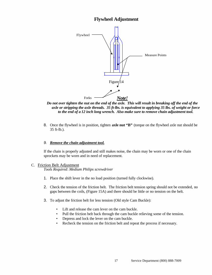
6. Before tightening axle nut “B”, the flywheel must be aligned. Alignment requires measuring thedistance from one side of the flywheel to the inside edge of the fork tube (Figure 14).Measurement should be taken at the top and bottom of the flywheel. These distances should beabout the same (difference should be no greater than 1/8 inch).
7. If the flywheel is out of alignment, be sure axle nut “B” is loose. Next, pull the top of the
flywheel to either side until the measurements on the top and bottom of the flywheel to the forkfall within the 1/8 inch tolerance (Figure 14).
Chain Tool
Figure 13
Correct
Incorrect
Chain tension tool
Axle nut “A”Tighten first.
Axle nut “B”Tighten last
Crank Arm
Service Department (800) 888-700917
Flywheel Adjustment
Figure 14
Note! Do not over tighten the nut on the end of the axle. This will result in breaking off the end of the
axle or stripping the axle threads. 35 ft-lbs. is equivalent to applying 35 lbs. of weight or forceto the end of a 12 inch long wrench. Also make sure to remove chain adjustment tool.
8. Once the flywheel is in position, tighten axle nut “B” (torque on the flywheel axle nut should be35 ft-lb.).
9. Remove the chain adjustment tool.
If the chain is properly adjusted and still makes noise, the chain may be worn or one of the chainsprockets may be worn and in need of replacement.
C. Friction Belt AdjustmentTools Required: Medium Philips screwdriver
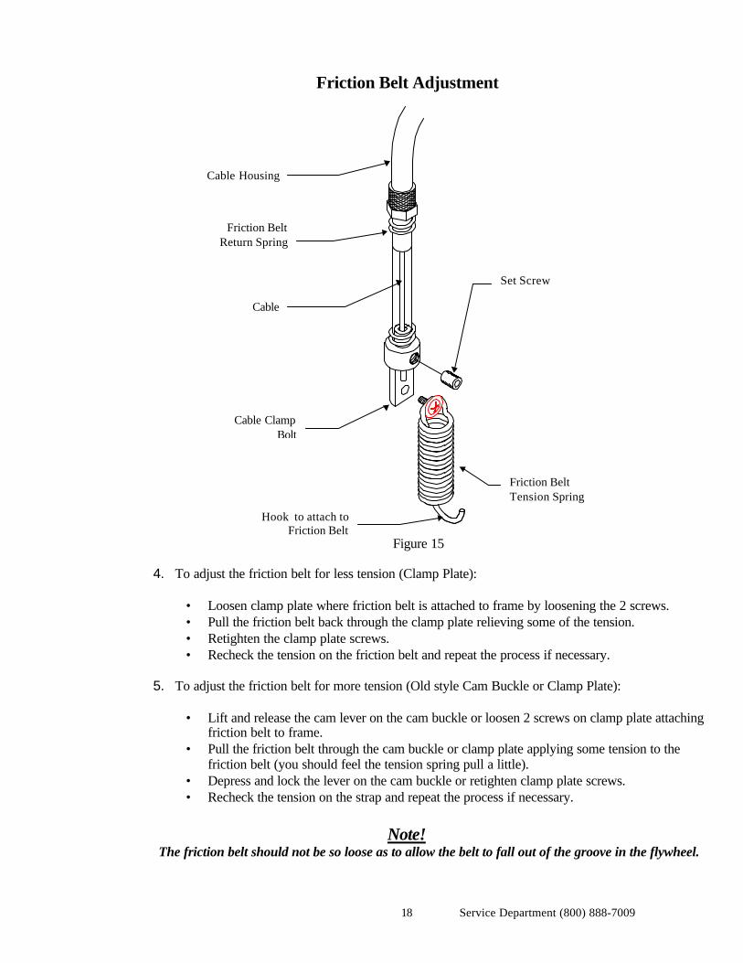
1. Place the shift lever in the no load position (turned fully clockwise). 2. Check the tension of the friction belt. The friction belt tension spring should not be extended, no
gaps between the coils, (Figure 15A) and there should be little or no tension on the belt.
3. To adjust the friction belt for less tension (Old style Cam Buckle):
• Lift and release the cam lever on the cam buckle.• Pull the friction belt back through the cam buckle relieving some of the tension.• Depress and lock the lever on the cam buckle.• Recheck the tension on the friction belt and repeat the process if necessary.
Measure Points
Flywheel
Forks
Service Department (800) 888-700918
Friction Belt Adjustment
Figure 15
4. To adjust the friction belt for less tension (Clamp Plate):
• Loosen clamp plate where friction belt is attached to frame by loosening the 2 screws.• Pull the friction belt back through the clamp plate relieving some of the tension.• Retighten the clamp plate screws.• Recheck the tension on the friction belt and repeat the process if necessary.
5. To adjust the friction belt for more tension (Old style Cam Buckle or Clamp Plate):
• Lift and release the cam lever on the cam buckle or loosen 2 screws on clamp plate attachingfriction belt to frame.
• Pull the friction belt through the cam buckle or clamp plate applying some tension to thefriction belt (you should feel the tension spring pull a little).
• Depress and lock the lever on the cam buckle or retighten clamp plate screws.• Recheck the tension on the strap and repeat the process if necessary.
Note!The friction belt should not be so loose as to allow the belt to fall out of the groove in the flywheel.
Friction BeltReturn Spring
Cable
Cable ClampBolt
Hook to attach toFriction Belt
Set Screw
Cable Housing
Friction BeltTension Spring
Service Department (800) 888-700919
D. Shift Lever TensionTools Required: None
1. If the shift lever inadvertently moves during the workout, the lever may be tightened to preventmovement.
2. To tighten the lever, rotate the shift lever tension bolt (see figure 10) clockwise until the desired
tension is achieved.
Note!Three things affect the shift lever tension range.
1.) Friction Belt2.) Flywheel3.) Shifter Cable Assembly
If these 3 items are not checked periodically your tension range will decrease, resulting in less load rangebetween your maximum and minimum tension.
E. Seat (Non - adjustable)Tools Required: 9/16 inch wrench
1. Attach the seat to the seat post such that the post is forward of the clamp bolt. Before tighteningthe seat clamp bolt, position seat so that it is level and is centered on the parallel section of the seatrails. Be careful to make sure that the clamp is not tightened at a position between serrations asthis may allow the seat to slip and damage the serration’s on the clamp.
2. Tighten the clamp so the seat will not tilt or rotate inadvertently.
F. Replacement of Friction BeltTools Required: None
1. Place the shift lever in the no load position (turned fully clockwise). 2. Release the cam buckle or clamp plate holding the friction belt in place. 3. Unhook the grommet on the other end of the friction belt from the friction belt tension spring. 4. Replace the old friction belt with a new one. 5. Place the end of the friction belt on the hook end of the friction belt tension spring. 6. Wrap the belt around the flywheel (felt against the flywheel) being careful not to twist the belt. 7. Insert the free end of the belt into the cam buckle or clamp plate and follow the instructions in
“Friction Belt Adjustment”.
Service Department (800) 888-700920
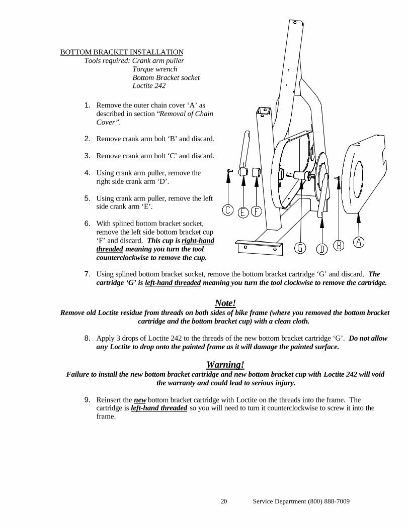
BOTTOM BRACKET INSTALLATIONTools required: Crank arm puller
Torque wrenchBottom Bracket socketLoctite 242
1. Remove the outer chain cover ‘A’ asdescribed in section “Removal of ChainCover”.
2. Remove crank arm bolt ‘B’ and discard.
3. Remove crank arm bolt ‘C’ and discard.
4. Using crank arm puller, remove theright side crank arm ‘D’.
5. Using crank arm puller, remove the leftside crank arm ‘E’.
6. With splined bottom bracket socket,remove the left side bottom bracket cup‘F’ and discard. This cup is right-handthreaded meaning you turn the toolcounterclockwise to remove the cup.
7. Using splined bottom bracket socket, remove the bottom bracket cartridge ‘G’ and discard. Thecartridge ‘G’ is left-hand threaded meaning you turn the tool clockwise to remove the cartridge.
Note!Remove old Loctite residue from threads on both sides of bike frame (where you removed the bottom bracket
cartridge and the bottom bracket cup) with a clean cloth.
8. Apply 3 drops of Loctite 242 to the threads of the new bottom bracket cartridge ‘G’. Do not allowany Loctite to drop onto the painted frame as it will damage the painted surface.
Warning!Failure to install the new bottom bracket cartridge and new bottom bracket cup with Loctite 242 will void
the warranty and could lead to serious injury.
9. Reinsert the new bottom bracket cartridge with Loctite on the threads into the frame. Thecartridge is left-hand threaded so you will need to turn it counterclockwise to screw it into theframe.
Service Department (800) 888-700921
Warning!Failure to torque the new bottom bracket cartridge to 57 ft-lbs. will void the warranty and could lead to
serious injury.
10. Using the splined bottom bracket socket on a torque wrench, tighten the cartridge bottom to atorque of 57 ft-lbs.
11. Apply 3 drops of Loctite 242 to the threads of the new bottom bracket cup ‘F’. Do not allow anyLoctite to drop onto the painted frame as it will damage the painted surface.
12. Reinsert the new bottom bracket cup with Loctite on it into the left side of the frame. The cup isright-hand threaded so you will need to turn it clockwise to screw it into the frame.
Warning!Failure to torque the new bottom bracket cup to 57 ft-lbs. will void the warranty and could lead to serious
injury.
13. Using the splined bottom bracket socket on a torque wrench, tighten the new bottom bracket cupwith Loctite on it to a torque of 57 ft-lbs.
14. Place the left side crank arm ‘E’ onto the spindle of the left side of the bottom bracket.
15. Place the right side crank arm ‘D’ onto the spindle of the right side of the bottom bracket.
Warning!Failure to follow the following instructions regarding applying Loctite 242 to the threads of the crank armbolts for both sides of the crank arm and for tightening both crank arm bolts to a torque of 30 ft-lbs. will
void the warranty and could lead to serious injury.
16. Apply 1 drop of Loctite 242 to new crank arm bolt ‘C’. Screw bolt into left side of frame andtorque to 30 ft-lbs. Do not allow any Loctite to drop onto the painted frame as it will damage thepainted surface.
17. Apply 1 drop of Loctite 242 to new crank arm bolt ‘B’. Screw bolt into right side of frame andtorque to 30 ft-lbs. Do not allow any Loctite to drop onto the painted frame as it will damage thepainted surface.
18. Reinstall the chain and tension it as described in the section “Chain Tension & FlywheelAdjustment”.
Service Department (800) 888-700922
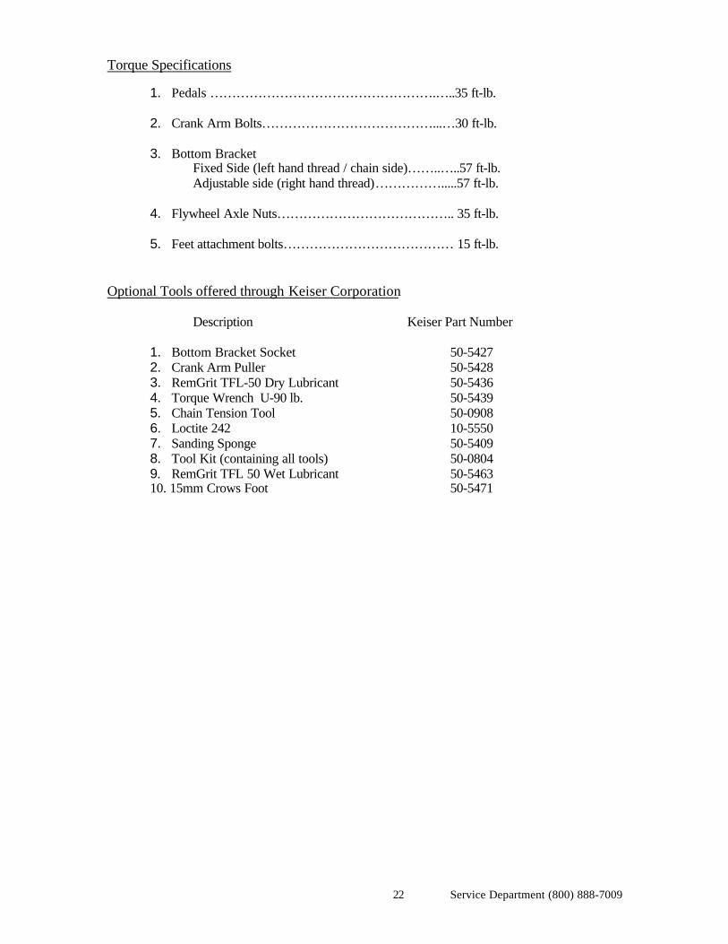
Torque Specifications
1. Pedals …………………………………………….…..35 ft-lb. 2. Crank Arm Bolts…………………………………...…30 ft-lb. 3. Bottom Bracket
Fixed Side (left hand thread / chain side)……..…..57 ft-lb.Adjustable side (right hand thread)…………….....57 ft-lb.
4. Flywheel Axle Nuts………………………………….. 35 ft-lb. 5. Feet attachment bolts………………………………… 15 ft-lb.
Optional Tools offered through Keiser Corporation
Description Keiser Part Number
1. Bottom Bracket Socket 50-54272. Crank Arm Puller 50-54283. RemGrit TFL-50 Dry Lubricant 50-54364. Torque Wrench U-90 lb. 50-54395. Chain Tension Tool 50-09086. Loctite 242 10-55507. Sanding Sponge 50-5409 8. Tool Kit (containing all tools) 50-08049. RemGrit TFL 50 Wet Lubricant 50-546310. 15mm Crows Foot 50-5471
Service Department (800) 888-700923
TROUBLESHOOTING
Vibration during use:Flywheel may not be adjusted properly. Follow procedures outlined in “Chain Tension & FlywheelAdjustment”.
Chain Falls off:Chain has too much slack. Follow procedures outlined in “Chain Tension & Flywheel Adjustment”.
Excessive Noise from Chain:Chain is too tight. Follow procedures outlined in “Chain Tension & Flywheel Adjustment”. Checkchain cover for rubbing or Chain is worn out. Replace chain.
Full Load not enough:Friction belt is out of adjustment. Follow procedures outlined in “Friction Belt Adjustment”. Ifadjustments are acceptable, check friction belt for worn spots.If worn, replace belt.
Load is too high:Friction belt is out of adjustment. Follow procedures outlined in “Friction Belt Adjustment”.
Warning!
Failure to follow the assembly or operation instructions as provided by this manualor any other instructions pertaining to the assembly and/or operation of KEISER
equipment will result in voiding the warranty and could lead to serious injury.

Service Department (800) 888-700924
FREE WHEEL (5000) / POWER PACER (5100)MECHANICAL BICYCLE
ITEM PART NO. DESCRIPTION ITEM PART NO. DESCRIPTION1 505410.80 SEAT-STANDARD 36 501810.80 BELT ANCHOR CLAMP PLATE3 500831.60 SEAT POST-NON ADJUSTABLE 37 9158.00 HHCS 1/4-20 X 2 1/4 SS4 500830.60 SEAT POST-ADJUSTABLE 38 9237.00 HEX ELAS LOCK NUT 3/8-16 UNC5 500832.60 QUICK REL W/ ADJ POST ASSY 39 9347.00 3/8 FLAT WASHER7 9265.00 PHCSS 1/4-20 X 3/4 SS 40 505416.00 16 TOOTH SPLD COG (PWR PACER)8 9035.00 SHCS 1/4-20 X 3/4” SS 41 505426.80 NUT 1 3/8-24 (PWR PACER)
10 9226.00 HEX REV LOCK NUT 5/16-18 UNC 42 500902.33 BOTTOM FRAME WITH CASTERS *11 505425.80 CHAIN 43 9279.00 HWH TFTDC 5/16-18 X 3/4 ZP12 505424.80 CRANK ARM-170MM S 44 505058.80 2" CASTER13 505403.80 PEDAL SET COMBO 45 505442.80 FRICTION BELT14 505444.00 PEDAL SET-STRAP/ TOE CAGE 46 505480.80 RIVET-PLASTIC FOR CHAIN GUARD15 505406.80 PEDAL SET-LOOK STYLE 47 505001.80 FLYWHEEL16 505464.80 REGULAR PEDALS 48 502200.80 FLYWHEEL AXLE17 115404.00 HOLE PLUG 1.0” 49 225400.00 BEARING 6203 2 SEALS18 115054.00 PLASTIC-CAP 2" SQUARE 50 505063.80 PLASTIC PIN 1/419 105423.00 BUMPER-MOLDED GLIDE 51 500901.33 HANDLE BAR WELDMENT20 504202.33 BOTTOM FRAME * 52 500810.00 SHIFT / CABLE ASSY.21 505060.80 CHAIN COVER-MALE / FEMALE 53 505407.80 RUBBER GROMMET22 265404.00 PLASTIC RIVET 54 105443.00 DECAL / SERIAL # LABEL23 9194.00 HHCS 5/16-18 X 3/4 SS 56 115371.00 KEISER DECAL – SMALL24 9369.00 AIRCRAFT WASHER 5/16 SS 58 505301.80 DECAL - POWER PACER25 505418.80 BEARING/AXLE ASSY-BOTTOM BRKT 59 505300.80 DECAL – FREE WHEEL26 500910.33 MAIN FRAME * 60 505408.80 FRICTION BELT TENSION SPRING27 172180.80 PLUNGER 62 505417.80 SPROCKET-16T (FREEWHEEL)28 175500.00 SPRING-PLUNGER 63 9219.00 HEX REV LOCK NUT 1/4-20 SS29 505302.80 DECAL-WARNING (BIKE) 64 9261.00 PHIL PH M/S 10-32 X 1/4 SS30 505068.80 BUSHING 4-PIECE 66 505495.80 NYLON WASHER31 502160.80 SLUG-HANDLE BAR ADJUSTMENT 67 505057.80 HANDLE BAR WIPER SEAL32 175420.00 BLACK KNOB 68 9007.00 COTTER PIN33 505470.80 WATER BOTTLE CAGE 69 215502.00 SPRING RING34 112244.00 THREADED NUT 70 9381.00 CRANK ARM BOLT35 505419.80 HANDLE STUD ASSY. 71 9178.00 HHCS 5/16”-18 X 2 ZP
* SPECIFIY COLOR

Service Department (800) 888-700925
KEISER SERVICE DEPT1 (800) 888-7009
KEISER CORPORATION2470 S. Cherry AvenueFresno, CA 93706-5004
(559) 256-8000
50-5500 Rev. H