table of contents - vertimax manual.pdftable of contents 1.0 receiving your ... wall types to secure...
TRANSCRIPT

VertiMax User Instruction Manual
Genetic Potential Inc. 4710 Eisenhower Blvd Suite A-6 Tampa, Fl 33634 800-699-5867
Table of Contents 1.0 Receiving your VertiMax……………………………… Page 1
2.0 Moving/Storage of the VertiMax……………………. Page 2
3.0 Stabilizing the VertiMax……………………….……… Page 3
4.0 Resistance Cord Procedures………………...……… Page 4
5.0 Basic Information on Your Resistance Cords………. Page 5
6.0 How to Determine Resistance Settings……………… Page 6
7.0 Waist Harness Attachment………………………….. Page 7
8.0 Hip Flexor Harness………………………………...…. Page 11
9.0 V4 Unit Basics………………………………………… Page 12
10.0 V6 Unit Basics………………………………………… Page 14
11.0 V6+ Unit Basics………………………………………… Page 17
12.0 V8+ Unit Basics………………………………………… Page 20
13.0 Hand Strap Attachment Procedure………………...... Page 24
14.0 Hand Grip Attachment Procedure……………………. Page 24
15.0 Shoe Attachment Procedure…….……………………. Page 25
16.0 Post-Training Procedure ………..……………………. Page 25
17.0 Hand Strap Configurations with the V6, V6+ & V8+ . Page 25
APPENDIX A - Training Guidelines……………………… Page 27

VertiMax User Instruction Manual
Page 1
1.0 Receiving your VertiMax1.1 Initial Setup Instructions After receiving your VertiMax unit, place the box on a flat surface and remove the box top. It is strongly recommended that 2 people are used to lift the unit out of the box. Grasp the unit in the stability tracking openings and place on a firm level surface. Place the VertiMax a safe distance from walls or other equipment to reduce the risk of accident or injury.
Please note:All accessories are located under the VertiMax unit and need to be removed after unit is taken out of the box. The plastic bags covering the pivoting tracking units need to be removed and properly disposed of. You also need to remove the rubber bands from the cords.
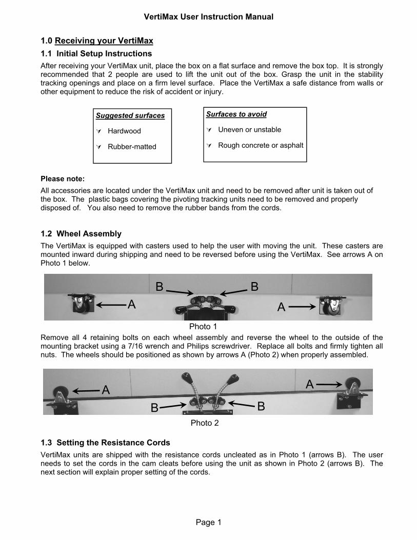
1.2 Wheel Assembly The VertiMax is equipped with casters used to help the user with moving the unit. These casters are mounted inward during shipping and need to be reversed before using the VertiMax. See arrows A on Photo 1 below.
Remove all 4 retaining bolts on each wheel assembly and reverse the wheel to the outside of the mounting bracket using a 7/16 wrench and Philips screwdriver. Replace all bolts and firmly tighten all nuts. The wheels should be positioned as shown by arrows A (Photo 2) when properly assembled.
1.3 Setting the Resistance CordsVertiMax units are shipped with the resistance cords uncleated as in Photo 1 (arrows B). The user needs to set the cords in the cam cleats before using the unit as shown in Photo 2 (arrows B). The next section will explain proper setting of the cords.
Suggested surfaces
Hardwood
Rubber-matted
Surfaces to avoid
Uneven or unstable
Rough concrete or asphalt
Photo 1
Photo 2
ABB
A
AB B
A
VertiMax User Instruction Manual
Page 2
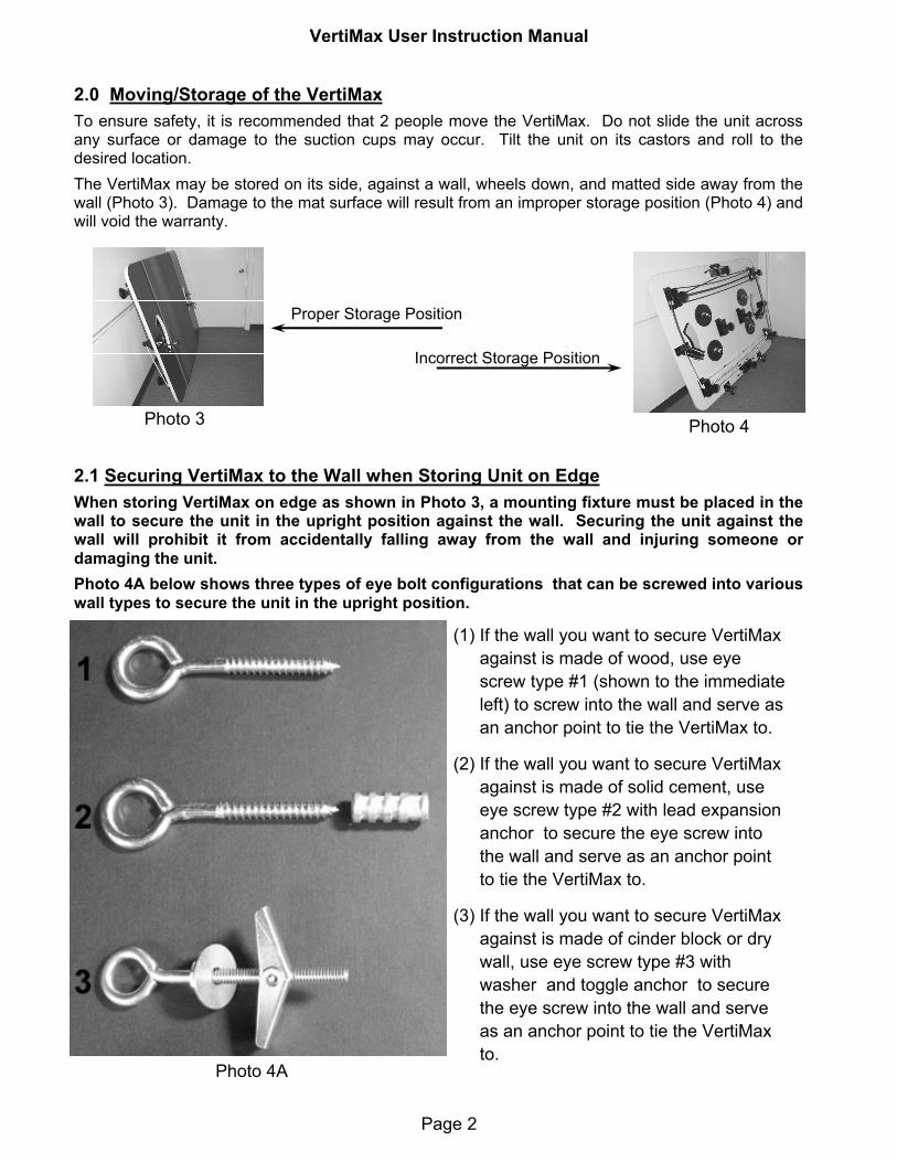
2.0 Moving/Storage of the VertiMaxTo ensure safety, it is recommended that 2 people move the VertiMax. Do not slide the unit across any surface or damage to the suction cups may occur. Tilt the unit on its castors and roll to the desired location. The VertiMax may be stored on its side, against a wall, wheels down, and matted side away from the wall (Photo 3). Damage to the mat surface will result from an improper storage position (Photo 4) and will void the warranty.
2.1 Securing VertiMax to the Wall when Storing Unit on EdgeWhen storing VertiMax on edge as shown in Photo 3, a mounting fixture must be placed in the wall to secure the unit in the upright position against the wall. Securing the unit against the wall will prohibit it from accidentally falling away from the wall and injuring someone or damaging the unit.Photo 4A below shows three types of eye bolt configurations that can be screwed into various wall types to secure the unit in the upright position.
Photo 3 Photo 4
Proper Storage Position
Incorrect Storage Position
(1) If the wall you want to secure VertiMax against is made of wood, use eye screw type #1 (shown to the immediate left) to screw into the wall and serve as an anchor point to tie the VertiMax to.
(2) If the wall you want to secure VertiMax against is made of solid cement, use eye screw type #2 with lead expansion anchor to secure the eye screw into the wall and serve as an anchor point to tie the VertiMax to.
(3) If the wall you want to secure VertiMax against is made of cinder block or dry wall, use eye screw type #3 with washer and toggle anchor to secure the eye screw into the wall and serve as an anchor point to tie the VertiMax to.
Photo 4A

VertiMax User Instruction Manual
Page 3
Each VertiMax is equipped with 4 Olympic sized weight studs located on the underside of the unit. The studs can hold 10 or 25-lb weights. Please refer to Photos 6-9 below for the weight mounting procedure. For safety, it is recommended that one person hold the VertiMax unit stable on its side while another applies the weights. The arrows in the Photo 5 indicate the po-sition of the 4 weight studs.
Photo 6 Unscrew wing nut from the stud.
Photo 7 Remove the wing nut and retaining bar.
Photo 8 Apply a 10 or 25-lb Olympic weight.
Photo 9 Replace the retaining bar on the stud and tighten wing nut.
Photo 5
3.0 Stabilizing the VertiMaxThe VertiMax is equipped with impact-absorbing suction cups that will hold it to a hard, smooth surface. If you wish to move the unit after training is completed, step off the unit and wait about 30 seconds for the suction to release, then carefully apply an upward force from a corner of the VertiMax. Do not forcefully pull on the unit or damage could occur to the suction cups. If the VertiMax is used on a surface in which the suction cups do not stick, then the unit may need to be stabilized with additional weights. This may be the case when training heavier ath-letes using more resistance.
The photo above shows how a simple rope can be used to thread through the eye screw and through the leg and then tied off to prohibit the VertiMax from accidentally falling away from the wall.

VertiMax User Instruction Manual
Page 4
4.0 Resistance Cord Procedures
The VertiMax resistance cords when shipped are not cleated in the cam cleats. Before you begin training on the unit, you must slide the cords between the cam cleats and allow the spring-loaded cams to cleat the cords automatically as shown in Photo 10.
4.1 Increasing or Decreasing the Training Resistance
The following procedures should be followed when changing the resistance of the VertiMax cords. By extracting or retracting the resistance cords from the unit, the training resistance is increased or decreased respectively.
Photo 11Press cords down to
release from cam cleats.
Photo 13 Raise the cords to lock
into the cam cleats.
Photo 12 Hold cords toward floor and extract to desired length.
To Decrease Resistance
Photo 15Hold cords toward floor
and allow them to retract.
Photo 16 Raise the cords to lock
into the cam cleats.
Important Note on Cord Adjustments
You MUST set the resistance BEFORE stepping on the VertiMax. Never attempt to adjust the cords while standing on the unit. Ex-tracting or retracting the cords while standing on the platform will damage both the cords and rubber molding on the side of the unit. Photo 17 shows incorrect cord adjustment.
To Increase Resistance
Photo 10
Photo 17
Photo 14Press cords down to
release from cam cleats.

VertiMax User Instruction Manual
Page 5
5.0 Basic Information On Your Resistance Cords
Referencing Photo 18 below, the underside of all four VertiMax models including the V4, V6, V6+ and V8+ units are identical. Each unit contains four individual resistance bands which run on a pulley sys-tem under the platform. The resistance of each of the four cords which protrude from the topside of the unit as shown in Photo 21 can be adjusted individually by the athlete. By extracting or retracting the ends of the four cords at points A, B, C and D, the resistances of cords 1, 2, 3 and 4 can be in-creased or decreased respectively.
Align resistance setting markers 3 black bands extracted
Photo 19 Photo 20
1
2
3
2
3 1
Photo 18 CORD 1 CORD 2
CORD 3 CORD 4
Extracting this cord end changes CORD 3 resistance.
Extracting this cord end changes CORD 4 resistance.
Extracting this cord end changes CORD 1 resistance.
Extracting this cord end changes CORD 2 resistance.
A
B
Each of the 4 cords that can be extracted from beneath the platform has 5 black bands each spaced approximately 11 inches apart (Photo 19) to help you determine the resistance settings after extract-ing or retracting the cords. When changing the resistance of the cords housed beneath VertiMax, al-ways make sure that both cords at extraction points A and/or point B (Photo 18) are equally extracted by aligning the black markers with one another (Photo 19). Verifying that the same number of black bands are visible on each cord after locking them in place ensures that the resistance on each cord is the same. Photo 20 illustrates a cord pair properly locked in place. The fact that both cord’s 3rd black band is locked approximately 1 inch from the platform’s edge ensures both cords are equally ex-tracted and thus both cord’s resistance is equal to one another.

VertiMax User Instruction Manual
Page 6
6.0 How To Determine Resistance Settings
The VertiMax comes standard with 3/8 inch resistance cords, or optional 5/16 inch youth cords. The charts below show the levels of resistance applied by both cords types based using 2 (Photo 21) or 4 (Photo 22) cord configurations and the number of black bands extracted from the unit. Column 1 (“Cord Config.”) specifies whether you have 2 or 4 cords attached to the user. Column 2 (“Marker Number”) specifies the number of black bans showing after a resistance adjustment has been made. Column 3 (“Lbs/Cord”) indicates the approximate lbs a single cord will apply if extracted to a specific black maker band as indicated in Column 2. Column 4 (“Approx Lbs”) indicates the approximate total load applied to the user based on the total number of cords attached.
Resistance Calibration Chart for Standard 3/8” Cord
CordConfig
Marker Number
Lbs / Cord
2 1 12 24 2 2 15 30 2 3 18 36 2 4 21 42 2 5* 24 48 4 1 12 48 4 2 15 60 4 3 18 72 4 4 21 84 4 5 24 96
ApproxLbs
Resistance Calibration Chart for Youth 5/16” Cord
CordConfig
Marker Number
Lbs / Cord
2 1 8 16 2 2 10 20 2 3 12 24 2 4 14 28 2 5* 16 32 4 1 8 32 4 2 10 40 4 3 12 48 4 4 14 56 4 5 16 64
ApproxLbs
* Please note that using the 5th resistance setting on a 2 cord setup is not recommended. Instead, use the lowest setting on a 4 cord set up for increased resistance level.
Photo 21 2 Cord Configuration
Photo 22 4 Cord Configuration
6.1 Example, Setting and Determining Resistance
A
B
The Illustration on the left shows all four cords extracted so that three black markers (or bands) are visible on each cord at ex-traction points (A) and (B). To determine the approximate exer-cise resistance the user would be subjected to in a “Two Cord” or “Four Cord” configuration, the charts above would be used in the following way: Assuming this is a system with 3/8” diameter cords, we would reference the 3/8” Cord Resistance Calibration chart in the upper left. Since three black markers are showing we would locate the row with the number “3” in the “Marker Num-ber” column and see that a single cord with 3 black markers ex-tracted would apply about 18 lbs. Each. Thus if we connected one cord to each side of our waist (2 Cord Configuration) we would have 18lbs X 2 = 36 lbs applied. If we connected two cords to each side of our waist (4 Cord Configuration) we would have 18lbs X 4 = 72 lbs applied.
PrimaryCords
1,2,3, & 4

VertiMax User Instruction Manual
Page 7
6.2 Additional Notes About Resistance Cords
For incremental resistance settings smaller than the 3 or 2 lbs increments shown respectively on the 3/8” and 5/16” calibration charts, you may lock cords half way between the black resistance markers. For instance, if you set a 3/8” system half way between the 1st and 2nd black marker, the approxi-mate resistance on the cord will be 13.5 lbs. This is calculated by observing that the 3/8” calibration chart indicates a resistance of 12 lbs for one black band and 15 lbs for two extracted black bands (a difference of 3 lbs). If you lock the cords half way between the first and second black band, then you will have a resistance increment of approximately half of 3 lbs or 1.5 lbs (reference Photos 23 and 24).
It is NOT recommended to use the 5th black band in the two cord configuration because the exer-cise resistance on each cord becomes less constant through the jumping motion as more black bands are extracted. Switching to a four cord configuration with all four cords extracted to the first black band on the 4 cord configuration provides the same 48 lbs of resistance that the two cord configuration provides with 5 black bands extracted.
The resistance cords will relax and stretch after extensive use. In this case the resistance will be less than what is listed in the chart by approximately 1-4 lbs.
It is normal for the nylon braiding around the resistance cords become worn or “fuzzy”, this will not affect their function or the unit function as a whole.
If the lowest resistance band is still too difficult for a user, then the resistance bands may be re-tracted to only 2 inches of cord exposure. This is accomplished by the athlete kneeling to one knee after the resistance bands have been connected to the waist (Photo 25). Then the training partner releases the cords and allows all but 2 inches of the cord to retract into the platform and then locks them in place (Photo 26). This will reduce the resistance by an additional 4-6 lbs.
Photo 25 3. User is to kneel to a knee.
Photo 26 4. Another person retracts cords except for the last 2” then locks the cleats.
Photo 24 2. Cords positioned in between 1 & 2nd bands.
Photo 23 1. Cords positioned at 1st band.
7.0 Waist Harness Attachment
The VertiMax unit comes with an adjustable waist harness. The harness should look like the Photo below and is comprised of: belt, left and right hip pad each with its own snap hook.
3 Belt Sizes Available
Youth: 24-30 inch waist
Medium: 28-41 inch waist
Large: 40-59 inch waist Photo 29
VertiMax Waist Belt

VertiMax User Instruction Manual
Page 8
Photo 30
Snap hooks
Photos 30—33 below illustrate the procedure for attaching the waist harness to the waist.
Sometimes while handling the waist belts the waist pads can slide off the belt. When this happens be sure to thread the belt through all three loops in each waist pad as shown in Photo 30.
Photo 31
Photo 31 illustrates the first few steps of fitting the waist harness about the user.
1. Apply the belt high around the waist line.
2. Feed the belt through the buckle cam.
3. Close the buckle cam with medium tension on the waist belt.
Photo 32
When attaching the waist harness the two hip pads will often slide out of position. Referencing Photo 32 we now align the hip pads in the proper position prior to firmly tightening the belt:
4. Adjust the position of each hip pad (by sliding them along the belt) so that each pad is centered on the left and right hip.
5. After the pads have been centered on each hip, unclamp the belt buckle and then re-tighten the belt firmly around the waist and then clamp the belt buckle again securing the waist harness.
Step 1
Step 2
Photo 33
Step 3
Referencing Photo 33:
6. After the waist belt is firmly tightened there may be 5 to 15 inches of excess belt protruding from the belt buckle. If such is the case, the user can tuck the excess belt through pad loops 1 and 3 (see Photo 30) to secure the belt end.
1 3
VertiMax User Instruction Manual
Page 9
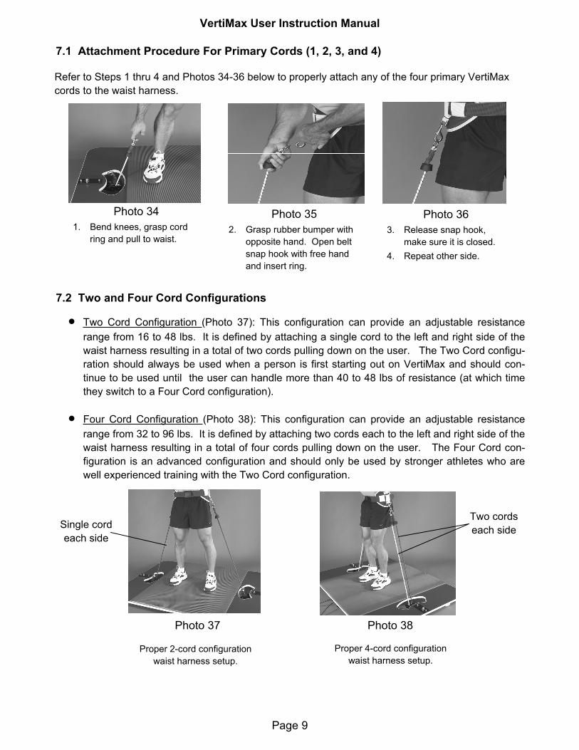
7.1 Attachment Procedure For Primary Cords (1, 2, 3, and 4)
Photo 34 1. Bend knees, grasp cord
ring and pull to waist.
Photo 35 2. Grasp rubber bumper with
opposite hand. Open belt snap hook with free hand and insert ring.
Photo 36 3. Release snap hook,
make sure it is closed. 4. Repeat other side.
7.2 Two and Four Cord Configurations
Two Cord Configuration (Photo 37): This configuration can provide an adjustable resistance range from 16 to 48 lbs. It is defined by attaching a single cord to the left and right side of the waist harness resulting in a total of two cords pulling down on the user. The Two Cord configu-ration should always be used when a person is first starting out on VertiMax and should con-tinue to be used until the user can handle more than 40 to 48 lbs of resistance (at which time they switch to a Four Cord configuration).
Four Cord Configuration (Photo 38): This configuration can provide an adjustable resistance range from 32 to 96 lbs. It is defined by attaching two cords each to the left and right side of the waist harness resulting in a total of four cords pulling down on the user. The Four Cord con-figuration is an advanced configuration and should only be used by stronger athletes who are well experienced training with the Two Cord configuration.
Proper 2-cord configuration waist harness setup.
Proper 4-cord configuration waist harness setup.
Photo 37 Photo 38
Refer to Steps 1 thru 4 and Photos 34-36 below to properly attach any of the four primary VertiMax cords to the waist harness.
Single cord each side
Two cords each side

VertiMax User Instruction Manual
Page 10
7.3 Detachment Procedure for Primary Cords (1, 2, 3, and 4)
When detaching the resistance cords from the waist you reverse the procedure shown in section 7.1 above. Grab the right cord by the rubber stopper with the right hand. Using your left hand re-tract the snap spring pin which secures cord ringlet to the waist harness (Photo 35).
After the ringlet is released from the snap hook continue to hold the cord in the right hand until it is fully retracted into the platform (Photo 40). Repeat this procedure on the left side while grasping the cord with the left hand. Never release any cord before it fully retracts to the platform sur-face, or damage to the unit and injury may result (Photo 41 illustrates an improper cord release).
Always unhook the cords from the waist harness before loosening the belt buckle.
If using 4 cords for the waist harness, remove the cords in the same sequence they were ap-plied. Release one cord from each side before releasing the final two. When training is com-pleted using a 4 cord configuration, never release two cords from the same side before releasing one cord from the opposite side. Referencing Photo 42, the athlete has incorrectly detached two cords from their right side before detaching at least one of the two cords from their left side. In such a case, when the athlete releases the one cord in their right hand the two cords pulling on their left can destabilize them causing them to fall.
Proper cord release requires lower-ing cord all the way down to the platform surface.
Never release any cord before it fully retracts to the platform surface.
In a four cord configuration, NEVER release two cords from one side be-fore releasing at least one cord from both sides first!
Photo 42 Photo 41 Photo 40
When the user progresses from the 2 cord configuration to the 4 cord configuration, it is important to remember to attach each side of the first set of cords before attaching the other set. ONLY AT-TACH ONE SET OF CORDS AT A TIME. Please refer to Photo 39 which shows the user incorrectly attaching 2 cords to their right side before attaching any cords to their left side. NEVER do this! If two cords are attached to one side first they will have the ten-dency to pull the user off balance, potentially causing them to fall and injure themselves.
Photo 39
If the waist harness should slip down during training, you must detach the resistance cords and reposition the harness as previously described in section 7.0.

VertiMax User Instruction Manual
Page 11
8.0 Hip Flexor Harness
The VertiMax unit comes with a left and right harness set for hip flexor training. The right harness is shown in Photo 40 while the attached left and right harness set is shown in Photos 41 and 42. Each harness should consist of a ring attachment, and a snap hook. Each is labeled for the left or right leg.
4 Hip Flexor Sizes Available (selected size depends on athlete height)
1) Youth (red & black): 4’10”- 5’6” (90-140 lbs) 2) Medium (blue & black): 5’7” - 6’2” (150-210 lbs)
3) Large (gray & black): 6’ - 6’5” (220-280 lbs) 4) Tall (all black): 6’6”+ (220-280 lbs)
Photo 41 Photo 42
8.1 Hip Flexor Attachment Procedure
8.2 Hip Flexor Attachment AdjustmentsIn some cases the hip flexor knee strap (see arrow on Photo 45 showing correct position just above the knee cap) may sit too high or low in the knee area. If this happens, the knee strap can be raised or lowered 1 or 2 inches by loosening the belt and moving the waist harness up or down 1 or 2 inches respectively followed by re-tighten the belt and then attaching resistance cords to the hip flexor har-ness. If the proper positioning can not be achieved with this slight adjustment, then a different size hip flexor attachment needs to be used. You can call Genetic Potential and order the proper size. It is not recommended that the unit be used if the attachment does not fit properly, nor should the user modify the attachment in any fashion.
1. Apply the waist harness as instructed.
2. Position the proper side hip flexor attachment and step through as shown.
Ring
Snap hook
Photo 40
Photo 43 Photo 44 Photo 45 3. Connect the waist harness
snap hook to the ring on the hip flexor attachment.
4. Make sure the snap is closed.
5. The thigh straps should sit just above the knee. (see arrow)
6. Ensure proper positioning of the attachment with thigh strap just above the knee.

VertiMax User Instruction Manual
Page 12
9.0 V4 Unit Basics
Photo 46 illustrates the most fundamental unit of the of the four VertiMax models, the V4. The V4 unit provides 4 resistance cords which emanate in pairs from a left and right tracking unit. Cords 1, 2, 3 and 4 provide four fixed resistance vectors that can attach to the user in pairs. The resistance of cords 1 and 2 are adjusted by extracting or retracting the cords at location (A). The resistance of cords 3 and 4 are adjusted by extracting or retracting the cords at location (B).
1
B
A
2
3 4
Left Tracking Unit Right Tracking Unit
This cord adjusts Cord 1’s resistance This cord adjusts Cord 2’s resistance
This cord adjusts Cord 3’s resistance This cord adjusts Cord 4’s resistance
Note on all units that the two cords exiting point (A) will be of the same color but always have a different color than the two cords exiting point (B). This helps users identify which cords to attach to themselves after they make a resistance adjustment on any cord pair at points (A or B). For example; if a user ad-justs the resistance of the white cord pair at point (A), they know they must attach the white cords 1 and 2 to their body. Alternately if the user adjusts the resistance of the red cord pair (darker colored cord) at point (B), they know to attach the red cords 3 and 4 to their body. Make sure after each resistance adjust-ment that both cords of a cord pair at points (A) or (B) are extracted equally (i.e. have the same number of black bands showing—reference Photo 20).
Photo 46
Sections 9 through 12 will provide basic information on each of the four VertiMax models that are available. Depending on which unit you own, proceed to the following sections:
VertiMax V4 Unit - Section 9
VertiMax V6 Unit - Section 10
VertiMax V6+ Unit - Section 11
VertiMax V8+ Unit - Section 12
Each section will provide basic operational information for each unit as specified including resistance adjustment and harness attachment configuration instructions.
VertiMax User Instruction Manual
Page 13
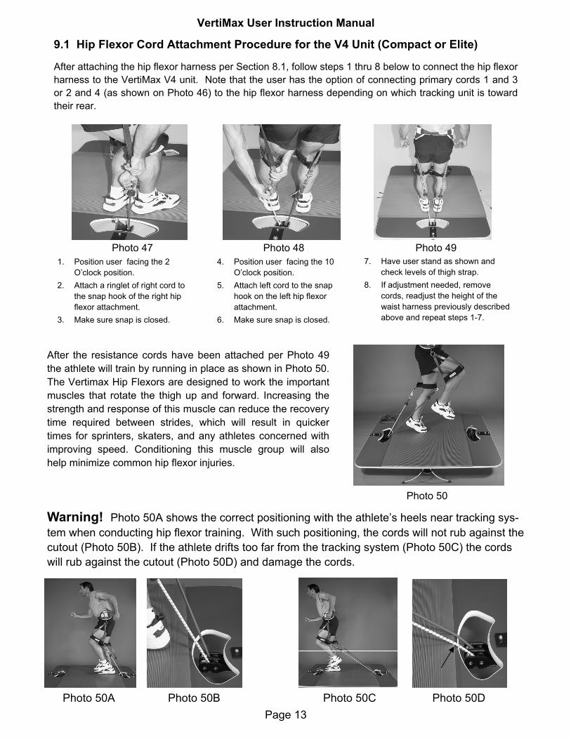
9.1 Hip Flexor Cord Attachment Procedure for the V4 Unit (Compact or Elite)
After attaching the hip flexor harness per Section 8.1, follow steps 1 thru 8 below to connect the hip flexor harness to the VertiMax V4 unit. Note that the user has the option of connecting primary cords 1 and 3 or 2 and 4 (as shown on Photo 46) to the hip flexor harness depending on which tracking unit is toward their rear.
1. Position user facing the 2 O’clock position.
2. Attach a ringlet of right cord to the snap hook of the right hip flexor attachment.
3. Make sure snap is closed.
4. Position user facing the 10 O’clock position.
5. Attach left cord to the snap hook on the left hip flexor attachment.
6. Make sure snap is closed.
7. Have user stand as shown and check levels of thigh strap.
8. If adjustment needed, remove cords, readjust the height of the waist harness previously described above and repeat steps 1-7.
Photo 47 Photo 48 Photo 49
Photo 50
After the resistance cords have been attached per Photo 49 the athlete will train by running in place as shown in Photo 50. The Vertimax Hip Flexors are designed to work the important muscles that rotate the thigh up and forward. Increasing the strength and response of this muscle can reduce the recovery time required between strides, which will result in quicker times for sprinters, skaters, and any athletes concerned with improving speed. Conditioning this muscle group will also help minimize common hip flexor injuries.
Warning! Photo 50A shows the correct positioning with the athlete’s heels near tracking sys-tem when conducting hip flexor training. With such positioning, the cords will not rub against the cutout (Photo 50B). If the athlete drifts too far from the tracking system (Photo 50C) the cords will rub against the cutout (Photo 50D) and damage the cords.
Photo 50A Photo 50B Photo 50C Photo 50D

VertiMax User Instruction Manual
Page 14
10.0 V6 Unit Basics
Referencing Figure 1, the six-cord V6 is an upgrade of the V4, in that it has two more topside resis-tance bands (R1 and R2) located on either end of the platform. Two fixed pulley assembles (P1 and P2) mounted to the platform surface allow a 5th and 6th band to be attached to the hands or ankles for numerous sports specific hand, leg and foot movements, such as kicking, hurdling, etc. Most trainers attach 5th & 6th cords to the hands so that athletes can experience a loading on the arms and shoul-ders while at the same time doing lower body reactive power training. This total body involvement fur-ther raises the vertical jump and first step quickness results achieved with the V4. (All exercises that could be done on the V4 can also be done on the V6. When felt appropriate, coaches can opt to use or not to use the two additional cords.)
1 2
43
5 6
B
AC D
This cord adjusts Cord 1’s resistance This cord adjusts Cord 2’s resistance
This cord adjusts Cord 3’s resistance This cord adjusts Cord 4’s resistance
This cord adjusts Cord 5’s resistance
This cord adjusts Cord 6’s resistance
Figure 1 - V6 Unit
R1 R2
P1 P2
10.1 Adjusting Resistance on the V6 Unit
Referencing Figure 1, cords 1, 2, 3, 4, 5, and 6 provide six rotational resistance vectors whose points of origin are fixed. Each resistance vector can be independently attached to the user. The resistance of cords 1 and 2 are adjusted by extracting or retracting the cords at location (A). The resistance of cords 3 and 4 are adjusted by extracting or retracting the cords at location (B) while the resistance of cords 5 and 6 are adjusted by extracting or retracting the cords at locations (C) and (D) respectively.
10.2 V6 Rotational Training Vectors
Figure 2 and Figure 3 on the following page illustrates how the six training vectors provided by cords 1 thru 6 may rotate about their fixed points of origin. Rotational vectors allow the user to move to any area of the exercise mat to conduct training while any number of cords 1 thru 6 are attached. IMPORTANTNOTE! Cords 5 and 6 may be attached to any part of the body from the foot to the shoulder. However, cords 1, 2, 3, and 4 should never be attached below the knee area or damage will result to the cords.
Exercise Mat

VertiMax User Instruction Manual
Page 15
10.2 Hip Flexor Cord Attachment Procedure for the V6 (Compact Unit)
After attaching the hip flexor harness per Section 8.1, reference Photo 51 on the following page and fol-low steps 1 thru 4 to connect the hip flexor harness to the VertiMax V6 unit.
1. Position user in the center of the mat facing forward with pulley assemblies P1 and P2 behind them.
2. Reach around to the left and grab the snap hook of the cord 5 emanating from the P1 pulley assem-bly and attach it to the snap hook on the right hip flexor attachment. Repeat attaching cord 6 emanat-ing from the P2 pulley assembly to the snap hook on the left hip flexor attachment.
3. The user should stand as shown in Photo 51 and check levels of thigh strap.
4. If the hip flexor straps are laying comfortably above the knee cap begin exercising. If an adjustment is needed, remove cords, readjust the height of the waist harness previously described in section 8.2 and then repeat steps 1-4 to reconnect cords 5 & 6 to the hip flexor and then begin exercising.
+35 deg
-35 deg
+35 deg
-35 deg
Cords 1 & 3 Cords 2 & 4
-90 deg
+90 deg
-90 deg
Figure 2Primary Cords 1-4 Rotational Range
Figure 3 Cords 5 & 6 Rotational Range
Cord 5 Cord 6
Figures 2 and 3 show how much each of the six resistance cords on the V6 unit can rotate about their fixed anchor point. Figure 2 illustrates that on all VertiMax models both primary cord sets (1 and 3) and (2 and 4) rotate +/- 35 degrees about the tracking assembly center point position. Figure 3 illustrates both cords 5 and 6 emanating from fixed pulley assemblies P1 and P2 can rotate +/- 90 degrees about their anchor point.
P1 +90 deg P2
Referencing Figure 2, if a user has cords 1 and/or 3 attached to their body they should not attempt to conduct exercises in the far corners of the left side of the exercise mat (Corners A and B). The +/- 35 degree rotational swing of the cords as the figure indicates does not allow either cord 1 or 3 to swing all the way to corner A or B. Likewise cords 2 and 4 cannot swing all the way to corners C and D. There-fore when cords 2 and 4 are attached to the body the user should avoid corners C and D. The +/- 90 de-gree swing of cords 5 and 6 shown in Figure 3 allow the user to exercise anywhere on the mat they de-sire when cords 5 and/or 6 are attached at any point on their body.
Corner A
Corner B
Corner C
Corner D

VertiMax User Instruction Manual
Page 16
It is important to note that if you are using an Elite size V6 unit, you should use the hip flexor cord at-tachment procedure for the V4 unit described in section 9.1. The Elite size V6 unit’s fixed pulley as-semblies P1 and P2 (Photo 52) are spread one foot wider (53 inches) than the Compact size unit’s fixed pulley assemblies (41 inches) shown in Photo 51. The 53 inch spread of the fixed pulley assem-blies on the Elite size unit causes cords 5 and 6 to pull outwardly on the athlete’s legs considerably more than cords 5 and 6 on the Compact size unit. Optimally for hip flexor training you want cords 5 and 6 to pull straight back on the legs. It is therefore recommended that when conducting hip flexor training on an Elite size V6 unit the user should be position as shown in Photo 50 on page 12.
41”P2 P1 53”P1 P2
Photo 51 Compact V6 Hip Flexor Setup
Photo 52 Less Optimal Elite V6 Hip Flexor Setup
6 56 5
VertiMax User Instruction Manual
Page 17
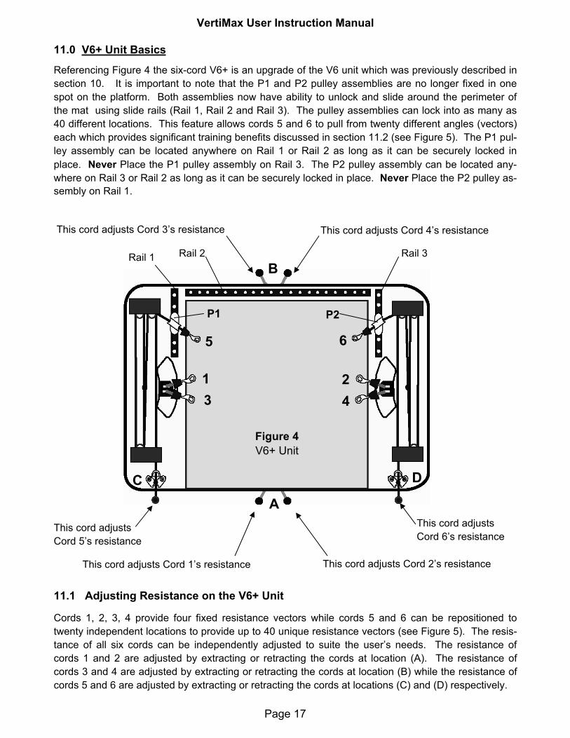
11.0 V6+ Unit Basics
Referencing Figure 4 the six-cord V6+ is an upgrade of the V6 unit which was previously described in section 10. It is important to note that the P1 and P2 pulley assemblies are no longer fixed in one spot on the platform. Both assemblies now have ability to unlock and slide around the perimeter of the mat using slide rails (Rail 1, Rail 2 and Rail 3). The pulley assemblies can lock into as many as 40 different locations. This feature allows cords 5 and 6 to pull from twenty different angles (vectors) each which provides significant training benefits discussed in section 11.2 (see Figure 5). The P1 pul-ley assembly can be located anywhere on Rail 1 or Rail 2 as long as it can be securely locked in place. Never Place the P1 pulley assembly on Rail 3. The P2 pulley assembly can be located any-where on Rail 3 or Rail 2 as long as it can be securely locked in place. Never Place the P2 pulley as-sembly on Rail 1.
Figure 4 V6+ Unit
1
B
AC D
23 4
65
P2P1
This cord adjusts Cord 1’s resistance This cord adjusts Cord 2’s resistance
This cord adjusts Cord 3’s resistance This cord adjusts Cord 4’s resistance
This cord adjusts Cord 5’s resistance
This cord adjusts Cord 6’s resistance
11.1 Adjusting Resistance on the V6+ Unit
Cords 1, 2, 3, 4 provide four fixed resistance vectors while cords 5 and 6 can be repositioned to twenty independent locations to provide up to 40 unique resistance vectors (see Figure 5). The resis-tance of all six cords can be independently adjusted to suite the user’s needs. The resistance of cords 1 and 2 are adjusted by extracting or retracting the cords at location (A). The resistance of cords 3 and 4 are adjusted by extracting or retracting the cords at location (B) while the resistance of cords 5 and 6 are adjusted by extracting or retracting the cords at locations (C) and (D) respectively.
Rail 1 Rail 2 Rail 3

VertiMax User Instruction Manual
Page 18
11.3 Configuring the V6+ Unit For Hip Flexor Training
The V6+ units are capable of altering the locations of cords 5 and 6 to configure a more efficient hip flexor training device than either the V4 or V6 units. The following instructions will detail two independent options to properly configure the V6+ unit for hip flexor training.
11.2 V6+ Multiple Training Vectors
The movable pulley assemblies P1 and P2 on the V6+ units allow cords 5 and 6 to be positioned in 40 different locations around the rear perimeter of the mat. Figure 5 illustrates the some of the many resis-tance vectors that the V6+ can apply to the user as P1 and P2 pulley assemblies are moved around the perimeter of the mat. Note that at each location for which the P1 and P2 pulley assemblies can be locked along the three guide rails, cords 5 and 6 can be directed to any location over the exercise mat.
P1 P2
Figure 5
11.3.1 Option 1 Hip Flexor Cord Attachment Configuration for the V6 + Unit
The following section describes the Basic hip flexor attachment configuration for all V6+ units (Compact and Elite models). Referencing Figure 6, the VertiMax V6+ units have guide rails mounted around the back perimeter of the exercise mat which allow the P1 and P2 pulley assemblies to be repositioned around the mat as indicated by the arrows. First position P1 and P2 pulley assemblies as shown in Fig-ure 7 and then follow steps 1-9 on the following page to properly configure the Option 1 hip flexor training configuration.
Figure 6 V6+ units have adjustable top pulley assemblies that can be repositioned to many locations on guide rails a indi-cated by arrows.
P1 P2
Figure 7 Prior to attaching resistance bands to the hip flexor harness, the user positions P1 and P2 pulley assemblies as shown.
P1 P2
5 6

VertiMax User Instruction Manual
Page 19
1. Place pulley assemblies P1 and P2 as shown on the rear adjustment rail (also refer-ence Figure 7).
2. Make sure pulley placement is the same distance from the end of each side of the adjustment rail.
3. Make sure both pulley as-semblies are locked in place.
4. Attach right cord 6 to the snap hook on the right hip flexor attachment.
5. Make sure snap is closed.
6. Step toward the left rear pulley (P1) and repeat step 4 with the left hip flexor har-ness.
7. Make sure snap is closed.
8. Have user stand as show and check that the thigh strap is just above the knee.
9. If adjustment needed, re-move cords, readjust the height of the waist harness as previously described in section 8.2 and then repeat steps 1-8.
Photo 53 Photo 54 Photo 55
11.3.2 Option 2 Hip Flexor Cord Attachment Configuration for the V6+ Unit
The Option 2 hip flexor configuration enables the user to apply a more consistent load to the hip flexor throughout the full range of the exercise motion. This is accomplished by attaching two cords to each hip flexor harness using cords 5 and 6 to pull backwards while cords 1 and 2 or cords 3 and 4 provide a downward pull. Figure 8 indicates which four cords on the V6+ unit are attached to the hip flexor har-nesses while photo 56 illustrates the completed Option 2 cord attachment configuration. Referencing Figure 8, the Option 2 hip flexor configuration is configured by attaching cords 5 and 6 to the left and right hip flexor harness respectively. Then the user will connect cords 1 and 2 or cords 3 and 4 respec-tively to the left and right hip flexor harness. Once all for cords are attached the actual configuration should appear exactly as Photo 56 indicates.
Figure 8
Option 2 is configured by attaching the P1 and P2 pulley assembly cords 5 and 6 behind the left and right knees respec-tively. The user will then attach cords 1 and 2 or cords 3 and 4 behind the left and right knees respectively.
P1 P2
1 2
3 4
Photo 56
Option 2 Hip Flexor Configuration
5 6A
Remember, prior to beginning your exercising check to make sure the hip flexor straps are laying com-fortably above the knee cap (see arrow (A) Photo 56). If the strap is below the top of the knee cap or more than 2 inches above the top of the knee cap, an adjustment will be needed. Remove the four
VertiMax User Instruction Manual
Page 20
cords, readjust the height of the waist harness appropriately as previously described in section 8.2 and then repeat the attachment procedure above. If the strap height above the knee cap is within limits (at the top of the knee cap or less than 2 inches above the knee cap) begin exercising.
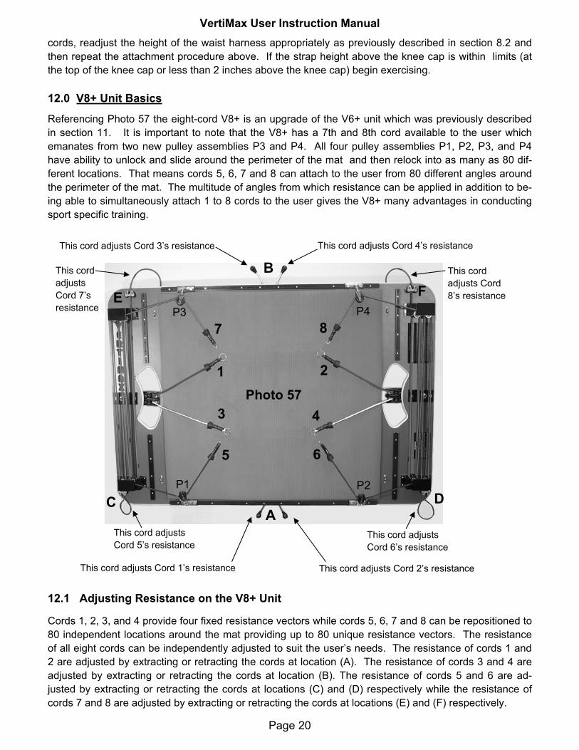
12.0 V8+ Unit Basics
Referencing Photo 57 the eight-cord V8+ is an upgrade of the V6+ unit which was previously described in section 11. It is important to note that the V8+ has a 7th and 8th cord available to the user which emanates from two new pulley assemblies P3 and P4. All four pulley assemblies P1, P2, P3, and P4 have ability to unlock and slide around the perimeter of the mat and then relock into as many as 80 dif-ferent locations. That means cords 5, 6, 7 and 8 can attach to the user from 80 different angles around the perimeter of the mat. The multitude of angles from which resistance can be applied in addition to be-ing able to simultaneously attach 1 to 8 cords to the user gives the V8+ many advantages in conducting sport specific training.
Photo 57 1
B
AC D
2
3 4
65
P2P1
This cord adjusts Cord 1’s resistance This cord adjusts Cord 2’s resistance
This cord adjusts Cord 3’s resistance This cord adjusts Cord 4’s resistance
This cord adjusts Cord 5’s resistance
This cord adjusts Cord 6’s resistance
87
E FP4P3
This cord adjusts Cord 7’s resistance
This cord adjusts Cord 8’s resistance
12.1 Adjusting Resistance on the V8+ Unit
Cords 1, 2, 3, and 4 provide four fixed resistance vectors while cords 5, 6, 7 and 8 can be repositioned to 80 independent locations around the mat providing up to 80 unique resistance vectors. The resistance of all eight cords can be independently adjusted to suit the user’s needs. The resistance of cords 1 and 2 are adjusted by extracting or retracting the cords at location (A). The resistance of cords 3 and 4 are adjusted by extracting or retracting the cords at location (B). The resistance of cords 5 and 6 are ad-justed by extracting or retracting the cords at locations (C) and (D) respectively while the resistance of cords 7 and 8 are adjusted by extracting or retracting the cords at locations (E) and (F) respectively.

VertiMax User Instruction Manual
Page 21
12.2 V8+ Multiple Training Vectors
The movable pulley assemblies P1, P2, P3, and P4 allow cords 5, 6, 7, and 8 to be positioned in 80 dif-ferent locations around the perimeter of the mat. Figure 9 illustrates the many resistance vectors that the V8+ can apply to the user as the four movable pulley assemblies are moved around the perimeter of the mat. Note that at each location for which the movable pulley assemblies can be locked along the six guide rails, cords 5, 6, 7 and 8 can be directed to any location over the exercise mat.
P1 P2
Figure 9
P3 P4
12.3 Configuring the V8+ Unit For Hip Flexor Training
The V8+ unit has all the capabilities of the V6+ unit. Therefore hip flexor training Configurations 1 and 2 described in sections 11.3.1 and 11.3.2 respectively can be used with the V8+ unit. There is a third hip flexor training configuration which is unique to the V8+ and more advanced than either Configurations 1 or 2 described in section 11. V8+ units are capable of placing all four moving pulley assemblies P1-P4 behind the athlete allowing for a hip flexor training configuration that is more advanced than either Op-tions 1 or 2. The following instructions will detail this third hip flexor training configuration option with in-structions to properly configure the V8+ for Option 3.
12.3.1 Option 3 Hip Flexor Cord Attachment Configuration for the V8 + Unit
The Option 3 hip flexor cord attachment configuration is only applicable to the V8+ unit. This option allows the user to apply more resistance to the hip flexors in the rearward direction relative to Op-tions 1 or 2. Figures 10 and 11 on the following page indicate how to position pulley assemblies P1, P2, P3 and P4 and which four cords on the V8+ unit are to be attached to the hip flexor harness.
VertiMax User Instruction Manual
Page 22
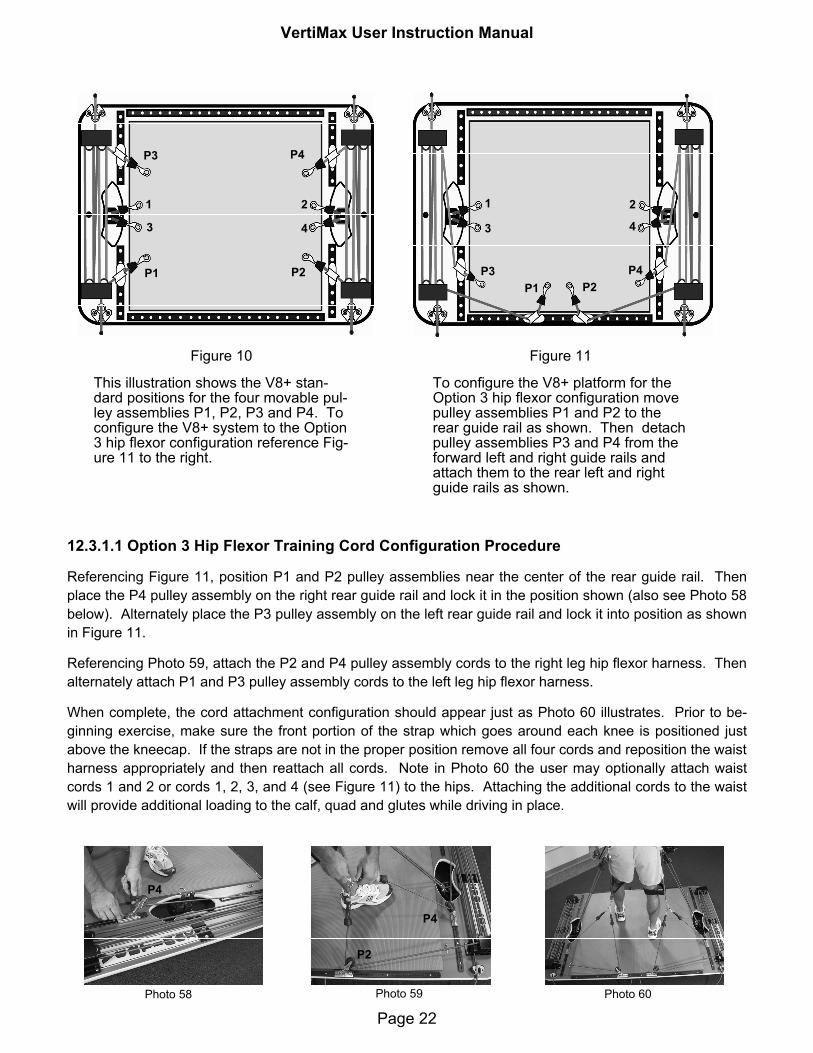
12.3.1.1 Option 3 Hip Flexor Training Cord Configuration Procedure
Referencing Figure 11, position P1 and P2 pulley assemblies near the center of the rear guide rail. Then place the P4 pulley assembly on the right rear guide rail and lock it in the position shown (also see Photo 58 below). Alternately place the P3 pulley assembly on the left rear guide rail and lock it into position as shown in Figure 11.
Referencing Photo 59, attach the P2 and P4 pulley assembly cords to the right leg hip flexor harness. Then alternately attach P1 and P3 pulley assembly cords to the left leg hip flexor harness.
When complete, the cord attachment configuration should appear just as Photo 60 illustrates. Prior to be-ginning exercise, make sure the front portion of the strap which goes around each knee is positioned just above the kneecap. If the straps are not in the proper position remove all four cords and reposition the waist harness appropriately and then reattach all cords. Note in Photo 60 the user may optionally attach waist cords 1 and 2 or cords 1, 2, 3, and 4 (see Figure 11) to the hips. Attaching the additional cords to the waist will provide additional loading to the calf, quad and glutes while driving in place.
Photo 58 Photo 59 Photo 60
Figure 10
This illustration shows the V8+ stan-dard positions for the four movable pul-ley assemblies P1, P2, P3 and P4. To configure the V8+ system to the Option 3 hip flexor configuration reference Fig-ure 11 to the right.
Figure 11
To configure the V8+ platform for the Option 3 hip flexor configuration move pulley assemblies P1 and P2 to the rear guide rail as shown. Then detach pulley assemblies P3 and P4 from the forward left and right guide rails and attach them to the rear left and right guide rails as shown.
P1 P2
P3 P4
1 2
3 4
1 2
3 4
P1 P2P3 P4
P4
P4
P2

VertiMax User Instruction Manual
Page 23
12.4 V8+ Attachment Options
The VertiMax V8+ unit gives the user all the features of the V8+ with 2 additional top side resistance cord attachments that can benefit training. This unit enables the user to utilize the hand attachments, hip flex-ors and waist attachments simultaneously. See Photos 61-64 for examples using the V8 model.
Photo 61
Photo 62
Photo 63
Photo 64
Proper waist, rear hip flexor, lateral hip flexor, and hand cord attach-ment technique.
Single waist attachment
Rearward thigh attachment
Lateral thigh attachment
Upper Extremity attachment
Proper 4 cord waist, rear hip flexor, and lateral hip flexor cord attach-ment technique.
Double waist attachment
Rearward thigh attachment
Lateral thigh attachment
Proper 4 cord waist, rear hip flexor, and rear hand cord attachment tech-nique.
Double waist attachment
Rearward thigh attachment
Upper extremity rear attachment
Proper 4 cord waist, rear hip flexor, and
front hand cord attachment technique.
Double waist attachment
Rearward thigh attachment
Upper extremity front attachment

VertiMax User Instruction Manual
Page 24
13. Hand Strap Attachment Procedure
All VertiMax models except for the V4 have hand strap attachments provided with the unit. The hand straps are labeled LEFT and RIGHT just as the hip flexor attachments are.
7. The hand strap when properly attached should look like the Photo above.
8. Repeat steps 1-7 with the opposite hand.
9. The hand strap is con-nected to the resis-tance cords utilizing the ringlet at the base of the hand strap.
5. Wrap the Velcro strap (A) under wrist, then be-hind your thumb and at-tach it to strap (B) as shown.
6. Press the Velcro straps together to ensure a se-cure connection.
14. Hand Grip Attachment Procedure
Hand grip attachments may be purchased and used with VertiMax V6, V6+, and V8+ units to increase the number of useful exercises that can be performed. The procedure for hand grip attachment follows.
1. Hand grips may be attached to the top side resistance cords of pulley assemblies P1, P2, P3, and P4 to conduct a wide range of upper body exercises.
2. Always verify each movable pulley assembly is locked into position before attaching grips.
3. Attach hand grips to the snap hooks found at each end of the cords protruding from the movable pulley as-semblies P1-P4 as shown.
4. Hand grips can be used on either hand there is no des-ignated left or right.
5. Make sure snap rings are closed and the pulleys are securely locked in before exercising.
Photo 65 Photo 66 Photo 67
Photo 68 Photo 69 Photo 70
1. Place Left or Right strap in the corresponding hand as shown.
2. The Left or Right label should be across the palm with label facing as above.
3. Velcro strap B should be behind the thumb as shown.
VertiMax User Instruction Manual
Page 25
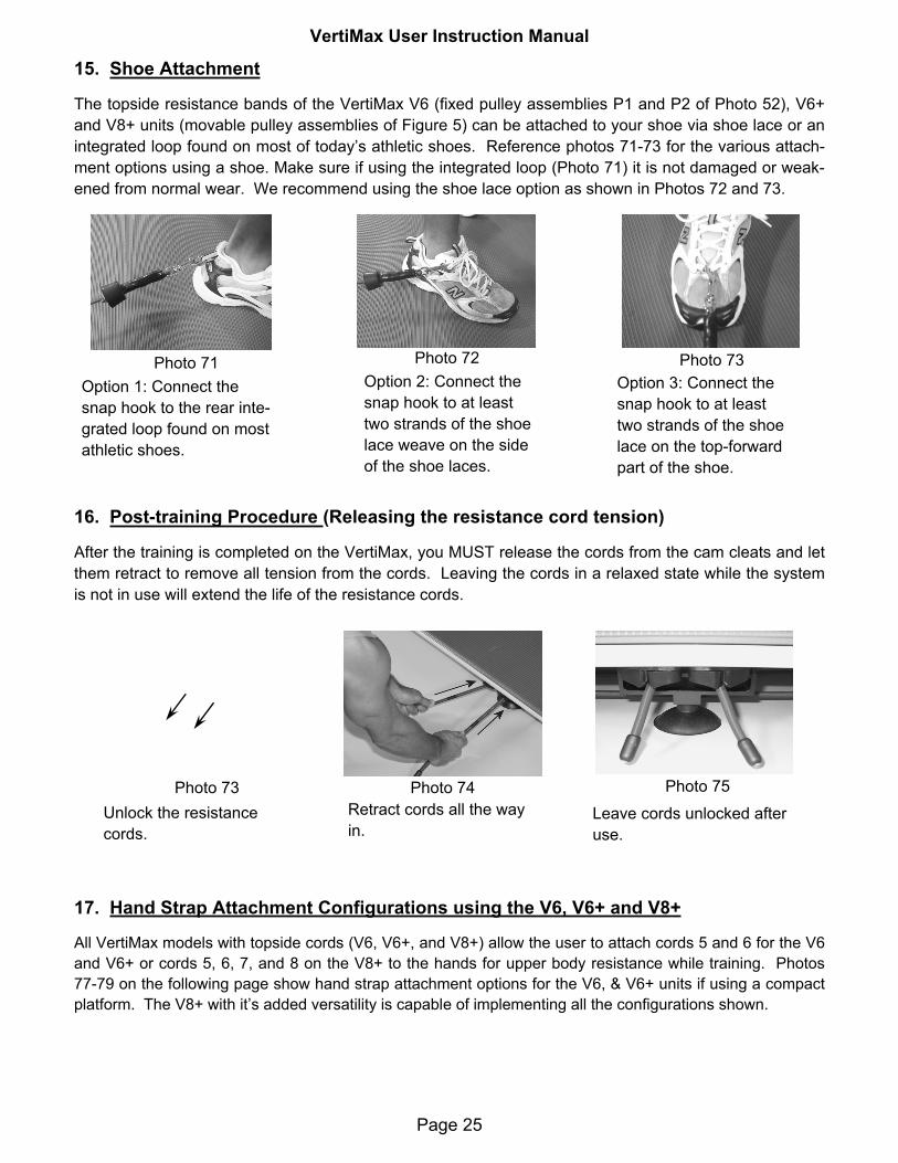
15. Shoe Attachment
The topside resistance bands of the VertiMax V6 (fixed pulley assemblies P1 and P2 of Photo 52), V6+ and V8+ units (movable pulley assemblies of Figure 5) can be attached to your shoe via shoe lace or an integrated loop found on most of today’s athletic shoes. Reference photos 71-73 for the various attach-ment options using a shoe. Make sure if using the integrated loop (Photo 71) it is not damaged or weak-ened from normal wear. We recommend using the shoe lace option as shown in Photos 72 and 73.
Option 1: Connect the snap hook to the rear inte-grated loop found on most athletic shoes.
Option 2: Connect the snap hook to at least two strands of the shoe lace weave on the side of the shoe laces.
Option 3: Connect the snap hook to at least two strands of the shoe lace on the top-forward part of the shoe.
Photo 73 Photo 72 Photo 71
17. Hand Strap Attachment Configurations using the V6, V6+ and V8+
All VertiMax models with topside cords (V6, V6+, and V8+) allow the user to attach cords 5 and 6 for the V6 and V6+ or cords 5, 6, 7, and 8 on the V8+ to the hands for upper body resistance while training. Photos 77-79 on the following page show hand strap attachment options for the V6, & V6+ units if using a compact platform. The V8+ with it’s added versatility is capable of implementing all the configurations shown.
16. Post-training Procedure (Releasing the resistance cord tension)
After the training is completed on the VertiMax, you MUST release the cords from the cam cleats and let them retract to remove all tension from the cords. Leaving the cords in a relaxed state while the system is not in use will extend the life of the resistance cords.
Leave cords unlocked after use.
Photo 74 Photo 75 Photo 73 Unlock the resistance cords.
Retract cords all the way in.

VertiMax User Instruction Manual
Page 26
Proper waist and rearward hand strap attachment con-figuration for V6 or V6+. 2 or 4 cords can be used on the waist harness.
Proper hand, waist and lateral hip flexor attachment for V6 or V6+.
Photo 79 Photo 77 Photo 78 Proper waist and forward hand strap attachment for V6+ . This configuration used for functional upper ex-tremity training exercises.
Page 27
A.1 Pre-Training Considerations Page 28
A.2 Introduction to Coaches Page 28
A.3 The Basic Jump Training Program Page 29
A.4 Training Philosophies and Protocols Page 30
A.5 Frequency of VertiMax Training Sessions Page 31
A.6 Choosing and Setting Resistances Page 32
A.7 Explanation of Training Jumps Page 33
A.8 Customizing the Program Page 35
A.9 Pre-Workout Safety Check List Page 39
VertiMax User Instruction Manual
Appendix A - TRAINING GUIDELINES

VertiMax User Instruction Manual
Page 28
A.1 PRE-TRAINING CONSIDERATIONS Prior to using VertiMax, each user must review this information. If he or she is unable to follow the directions and heed these cautions, they should not use Vertimax.
1. Are you physically fit to use Vertimax? Don’t enter into any training routine without a physical examination by a medical doctor. It is wise to inform the examining physician of the nature of the training routine you anticipate carrying out.
2. Make sure you know the correct form and exercise technique before attempting to use Verti-Max. Using improper form and techniques will inhibit optimum gains and may cause injury.
3. Make sure you warm up properly and perform safe stretching exercises prior to using Verti-Max.
4. Be careful not to over exert yourself when using VertiMax, especially during your first few workouts. Overwork and lack of rest will increase the risk of injury.
5. Prior to exercising make sure the connecting rings and clasps are free of damage, functioning correctly, and properly attached.
6. Prior to exercising make sure the cords are not worn, cut or frayed. If they are, do not use VertiMax until they have been replaced.
A.2 INTRODUCTION TO COACHES Today’s training is a complex business, that’s why there are certified strength and conditioning specialists at the top levels. These qualified individuals draw from a wide variety of training pro-tocols. The most effective routines are taken from the following three types of protocols: (1) Heavy Resistance, (2) Low-Load/Velocity-Specific training (previously called Light-load/High-Speed), and (3) Plyometrics. VertiMax training represents the second category, and is an es-sential part of any Speed-Agility-Quickness program. However, even if VertiMax training is con-ducted without either of the other two types of training, it will still markedly increase lower body reactive power and result in the following three competitive advantages:
(1) Large gains in an athletes’ vertical jump and first-step-quickness.
(2) A visible improvement in an athlete’s ability to accelerate, decelerate, and make more rapid and controlled competitive moves.
(3) Increased intensity and stamina during competition. While the basic training program does not take a long time to accomplish, it is a "high intensity, minimum recovery time” program that builds power endurance.
It is important that coaches recognize all three benefits of VertiMax training. The capabilities de-veloped through VertiMax training are HIGHLY TRANSFERRABLE TO THE FIELD OF PLAY. Vertimax training will make a visible contribution to physical performance on the field of play.This being the case, coaches should strive to schedule VertiMax as a priority activity, on a regu-lar basis! Consistency in VertiMax training is of the utmost importance! (You can’t just drag it out every three weeks and hit it real hard.)

VertiMax User Instruction Manual
Page 29
In addition to accomplishing VertiMax training on a regular basis, the next most important ele-ment in VertiMax training, is that the athlete put forth a maximum effort on every jump! In life, nothing great is ever achieved by working at 90%. If you're training for speed, you have to train at speed. Coaches must motivate their athletes to understand that it is the athlete himself who controls the level of his achievement, not the coach, not the machine. The athlete must be de-termined to jump higher on each successive jump; to put more effort on rep 3 than 2, and more effort on his 4th jump than on his 3rd jump.
NOTE: As in the use of any piece of equipment, it is never better than the instructor supervising the training. One key to success with the VertiMax is the knowledge, direction, and enthusiasm of the instructor. As the manufacturer, we sincerely urge coaches and trainers to use their initia-tive and put forth their best effort in scheduling, supervising, and monitoring VertiMax training.
A.3 THE BASIC JUMP TRAINING PROGRAM (GOOD FOR TEAM TRAINING)The Basic Program consists of a total of eight sets (six resisted):One "Warm-up" set (unresisted) Two sets of "Half-Quicks" Four sets of "Quarter-Quicks" One "Contrast" set (unresisted)
Sets and Reps
NOTE 1: This Basic Program shows 10-12 reps. The main reason for the higher reps and lower number of sets shown is to help sports coaches get more players across the platform in less time. For S&C coaches and professional trainers able to do one-on-one training, better results in explosive leg power will be achieved by doing less reps, but more sets.NOTE 2: Coaches should critique their athlete’s jumping skills before commencing resisted training. Have your athletes demonstrate that they can perform a coordinated jumping motion (take-off and landing) without any resistance. Some individuals may require training in 'jump mechanics' before commencing resisted training. NOTE 3: Regards Younger Athletes: VertiMax training is a demanding training activity. When a younger or smaller athlete first begins VertiMax training, it will not look pretty. Most of them have two deficits: (1) a lack of technique in performing the training jumps, and (2) a lack of stamina. Supervisors of younger (pre-teen) athletes should expect that during first three to five training sessions, the younger athlete may be temporarily discouraged, and positive results may be de-layed until he or she has learned the techniques and gained the stamina for proper training.
TrainingJumps
Cord Config. # of BandsShowing
# ofSets
# ofReps
Warm-up Jumps No Resistance - 1 10Half Quick Two Cord Config One 2 10 – 12
Quarter Quick Two Cord Config One 4 10 – 12 Contrast Jumps No Resistance - 1 6
VertiMax User Instruction Manual
Page 30
A.4 TRAINING PHILOSOPHIES/PROTOCOLS A.4.1 What's the Best Number of Reps to Do. If you're training for speed, you have to train at speed! The experts say that after the fourth or fifth rep - due to fatigue buildup, the athlete is no longer able to produce a maximum effort, and is therefore no longer training for peak "power production." Unknowingly, as of the sixth rep he has commenced working on "power endurance." So should we only do five reps? No, not nec-essarily. Higher reps are not always wasted. Some sports are "power endurance" (stamina) critical, such as lacrosse and soccer. To focus on increasing this capability, the 10-12 reps is fine. Conversely, a volleyball front line player is not 'stamina challenged', he or she is more "power production" critical, having repeated periods at an almost at-rest status before having a sudden requirement for maximum explosiveness. To best handle this requirement, doing just six reps, and doing additional sets is best. In summary it might be said,
If you want to jump higher at the beginning of next week's game than you did at the be-ginning of last week's game, do more sets of the 6-rep program.
If you're satisfied with you vertical, but you want to be able to jump just as high at the final buzzer as you did at the start of your game, you can do the higher 10/12-rep program
A.4.2 What's the Best Number of Sets to DoThe memorization process/post-training response is proportionate to the number of events (reps). No matter which rep-program you are doing – low or high, THE MORE SETS, THE BET-TER! (Especially if you are doing the low rep (6 rep) program.)
A.4.3 How Much Rest Between SetsVertiMax training is one type of training where having too much time between sets is better than not having enough time between sets. The more recovery time an athlete has, the more effort and speed he can generate on the next set. Rest periods range from 35 seconds to two min-utes depending on how many repetitions per set and the resistance level. Basically, the more fatigued an athlete is at the end of a set, the more rest time required. Athletes are normally on the platform for 20 to 30 seconds. If you are doing VertiMax training with groups of four, athlete #1 would have a minute and a half rest before his rotation comes up again. (Athletes #2, #3, & #4, would have each been on the platform for 30 seconds; thus each of the four athletes gets approximately a minute and a half for each set.
A.4.4 What Kind of Activities Are Acceptable Between SetsMuscle memory and post-training improvements are optimized if trainers do NOT schedule other lower body exercises between the VertiMax sets. Either allow the athlete to completely rest for that one and a half minutes, or schedule him for upper body or core exercises during that time period.
VertiMax User Instruction Manual
Page 31
A.5 FREQUENCY OF VERTIMAX TRAINING SESSIONSOff Season and Pre-Season:The program can be carried out as often as the coach deems advisable. Three times a week is normal. Every other day is recommended. During the off-season the emphasis should be on increasing Absolute Strength (through weight training). Then, as the season nears, the em-phases should switch to RATE of force development training - more Vertimax (light-load, high-speed) training. During the season:The regularity depends on the number of practice sessions or games scheduled. 1. Preferably – still three times a week, but with a reduced number of sets. For example, just
four resisted sets instead of six. (The 2 sets of "Half-Quicks" can be omitted, just do the 4 sets of "Quarter-Quicks.")
2. Or, still do all six resisted sets, but just do them twice a week. (Choosing those times which allow at least 24 hours before scheduled competition.)
A.5.1 VertiMax Training In Conjunction with Heavy Resistance Training
Coaches can evaluate the needs of the sport position or event of the athlete, to design the most effective program. For instance: in basketball, the athlete is rarely overcoming a resis-tance in excess of his own bodyweight, so two days of weight training and three days of Verti-Max may produce optimum results. However, in football, - particularly down linemen, a better ratio might be three days of weight training and two days of VertiMax. (Many football coaches still have their skill positions do two days of weight training and three days of VertiMax train-ing.)
A.5.2 Sequencing VertiMax Training with Weight Training The ideal method is to do the VertiMax training on the days that weight training is not sched-uled. If it is expedient to do both types of training on the same day, the VertiMax training should precede the lower body weight training. This sequencing will not detract from the weight training, and the VertiMax training can serve as a warm-up for the weight training. More importantly, this sequence allows the athletes to commence VertiMax (high speed) training with unfatigued legs. An exception to this sequence is when you are doing “Complex” routines - combining heavy resistance and pure plyo with light load training. (See “Advanced Routines” later in the manual.)
A.5.3 Training Session Time – Single Athlete The basic program includes eight sets. Each of those sets takes approximately one minute to accomplish (20 seconds on the platform and 40 seconds to rest). Therefore, one athlete can accomplish the entire eight-set program in eight minutes.
A.5.4 Training Session Time - Team Training The good news is that three athletes can do the whole program in eight minutes as well. Each of the three athletes occupies the platform for 20 seconds. All three finish their first set in the first minute. SO, FOR YOU HIGH SCHOOL SPORT COACHES, THIS MEANS IF YOU HAVE A 15-MAN SQUAD, YOU CAN BE DOING GAME SKILLS INSTRUCTION WITH 12 PLAYERS

VertiMax User Instruction Manual
Page 32
WHILE THREE ARE ON THE VERTIMAX. When those three are finished, they will rejoin your group and give their waist harnesses to three other players. Fifteen athletes can do the whole 8-set program in just 40 minutes.
NOTE: While it does not take long for one athlete to remove his waist harness and give it to the next athlete, more rapid cycling of athletes across the platform is greatly assisted when the ath-lete "on deck" is already belted up. Many coaches order a second or third, or even a fourth waist harness with their VertiMax. This way not only two, but three or four athletes can be belted up and ready to jump in when the athlete before them finishes his set. The minimum number of waist harnesses for optimum team training is two. Athlete #1 gives his waist harness to athlete #3 while athlete #2 is doing his set. When he is finished, athlete #2 can give his waist harness to athlete #4 while #3 is doing his set.
As shown below, when one athlete finishes his set, the next athlete to perform a set will step onto the platform. The new athlete may either use the other set of cords, or the same cords used by the first athlete. If using the same cords, they can simultaneously detach one set of cords from the athlete that just jumped and attach them to the athlete who will perform the next set. This procedure will allow the new athlete to connect to VertiMax in 5-10 seconds. Multiple athletes (each with their own waist harness) using this method can train simultaneously on one VertiMax unit, with very little 'down time.'
A.6 CHOOSING AND SETTING THE PROPER EXERCISE RESISTANCE A.6.1 Determining the Proper Starting Exercise Resistance The experts say that the optimum resistance for Low-Load Velocity-Specific training would be an amount that reduces the athlete’s best non-resisted jump by 30%. In other words if an ath-lete’s best non-resisted jump is 30 inches, the optimum training resistance for him to use would be an amount that still allows him to jump (70%), = 21 inches.
Many professional trainers use slightly more resistance, such that the athlete’s best non-resisted jump is reduced by 40%. Thus a 30 inch jump would be reduced to (60%) = 18 inches.
Some successful trainers, administering four-week protocols before a combine or 'measurement day', during the last week, increase the resistance to an amount that reduces the non-resisted attempt to 50%. (Thus a 30 inch jump would be reduced to 15 inches.) The main rule of thumb is to see if the athlete is jumping with an explosive/ballistic movement on each rep.

VertiMax User Instruction Manual
Page 33
A.6.2 Increasing the Resistance The size and strength of the athlete will determine how rapidly the resistance is increased. The best method is to do it in small increments, for example, when ready for more resistance, pull the cords out further – maybe half the distance to the next black marking, which would represent a 1-1/2 pound increase on each cord. (= 3 pounds total.) Usually, athletes can increase the re-sistance once every week or ten days. As athletes gain strength, they will be able to extract more cord out, until in the Two-Cord configuration, some are exercising at the fourth black band. We do not use the fifth black band in the Two-Cord Configuration. Instead, for increased resis-tance, the athlete will now switch to the Four-Cord Configuration with just one black band show-ing on all four cords.
A.6.3 How Many Pounds of Resistance Am I Using? A Calibration Chart is provided on page 5 so athletes can know approximately how many pounds of resistance is represented by each of the black markings. However, athletes should not be pre-occupied with what the exact poundage is. They should just note how many black marks are showing outside the edge of the platform (how far they have extracted the cords).
IMPORTANT
When the set is finished, and the athlete is unhooking the cords from his waist har-ness, HE MUST HANG ONTO THE CHROME RING, AND LOWER IT ALL THE WAY TO THE TRACKER BY HAND. Do NOT let it snap back down.
When the exercise session is complete, RELEASE ALL FOUR CORDS FROM THE CAM CLEATS and allow them to retract all the way in under the platform!
A.6.4 VertiMax is a “load memory” enhancing device
The objective is NOT to see who can use the most resistance, or get to the "Four-Cord" Con-figuration first. Do not be in a rush to increase resistance. (Light loads representing only 15% of an athlete’s body weight will produce great results.) The key is that the motion and effort be the same for each rep, each set – rhythmic and explosive! For the optimum training adapta-tions, all the repetitions must be done with a maximum effort.
A.7 EXPLAINATION OF TRAINING JUMPS
A.7.1 Un-resisted "Warm Up" Jumps In addition to an off-platform warm-up, Warm-up Jumps with no cords attached should always be done. They should consist of one set of ‘Quarter Quick’ Jumps (Explained in Section A.7.3) These warm up jumps are done at 50% effort, with no pause between attempts.
A.7.2 The "Half-Quick" Jumps Referencing photos 1-10, the athlete begins in the standing position (1) and then squatting until the thighs are almost parallel with the floor (4). The knee bends 80-90 degrees. The Half Quick jump is a Single Response Jump - the athlete will pause between attempts (10), and stand

VertiMax User Instruction Manual
Page 34
before dipping for the next attempt. Each jump is done with maximum effort - striving for maxi-mum height. Each rep should be done to the same depth, speed and tempo.
1 2 3 4 5
6 7 8 9 10 (Pause)
A.7.3 The "Quarter-Quick" Jumps This is also a resisted set. In this jump, the athlete only dips until the thigh is at a 45 degree an-gle (see photo13). The Quarter Quick jump is a Multiple Response Jump. Upon landing, the athlete will sink down to the new jump initiation position (thighs at 45 degrees) (15) and push off again for the next attempt, with no pause between reps. Each rep should be done with a maxi-mum effort – attempting to "out-do" the previous jump. (See photos 11-19 below.)
11 12 13 14 15
16 17 18 19
VertiMax User Instruction Manual
Page 35
A.7.4 The "Contrast" Jump
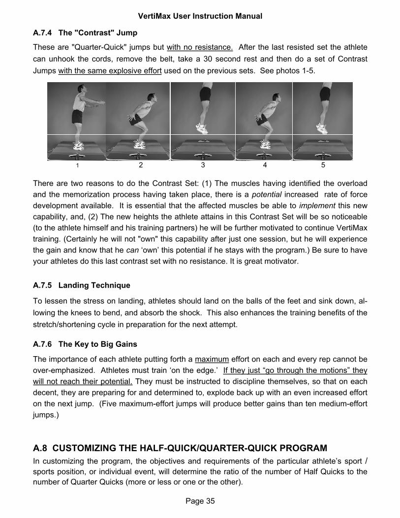
These are "Quarter-Quick" jumps but with no resistance. After the last resisted set the athlete can unhook the cords, remove the belt, take a 30 second rest and then do a set of Contrast Jumps with the same explosive effort used on the previous sets. See photos 1-5.
There are two reasons to do the Contrast Set: (1) The muscles having identified the overload and the memorization process having taken place, there is a potential increased rate of force development available. It is essential that the affected muscles be able to implement this new capability, and, (2) The new heights the athlete attains in this Contrast Set will be so noticeable (to the athlete himself and his training partners) he will be further motivated to continue VertiMax training. (Certainly he will not "own" this capability after just one session, but he will experience the gain and know that he can ‘own’ this potential if he stays with the program.) Be sure to have your athletes do this last contrast set with no resistance. It is great motivator.
1 2 3 4 5
A.7.5 Landing Technique
To lessen the stress on landing, athletes should land on the balls of the feet and sink down, al-lowing the knees to bend, and absorb the shock. This also enhances the training benefits of the stretch/shortening cycle in preparation for the next attempt.
A.7.6 The Key to Big Gains
The importance of each athlete putting forth a maximum effort on each and every rep cannot be over-emphasized. Athletes must train ‘on the edge.’ If they just “go through the motions” they will not reach their potential. They must be instructed to discipline themselves, so that on each decent, they are preparing for and determined to, explode back up with an even increased effort on the next jump. (Five maximum-effort jumps will produce better gains than ten medium-effort jumps.)
A.8 CUSTOMIZING THE HALF-QUICK/QUARTER-QUICK PROGRAMIn customizing the program, the objectives and requirements of the particular athlete’s sport /sports position, or individual event, will determine the ratio of the number of Half Quicks to the number of Quarter Quicks (more or less or one or the other).

VertiMax User Instruction Manual
Page 36
For athletes who must overcome a resistance in excess of their own body weight, and who often initiate their elevation from a lower stance (such as football down linemen and wres-tlers) the program could have more Half Quicks (at a higher resistance) and less Quarter Quicks.
For athletes who in their sport are not required to overcome a resistance other than their own body weight, and, who in their sport do not have the time to assume a low squat position be-fore initiating their jump (such as all basketball positions, volleyball from line players, and wide receivers) may well want to do less sets of the Half-Quicks (above) and more sets of the Quarter-Quicks.
A.8.1 Making the Training More Sports Specific
When used in the training room, another player can stand in front of the jumping athlete and throw him high passes or pump fakes overhead, left and right, while the player jumps to catch or block the intended pass. (Some coaches do this with a medicine ball, and have the athlete pass it back after one jump with it.)
For basketball coaches, the unit can be placed under the backboard – using the rim or back-board as a target for dunk or touch drills.
For volleyball coaches, the unit can be placed in front of the net, and players can practice spik-ing and roofing while strapped into the Vertimax.
NOTE: Regardless of the satisfaction of doing these sports-specific drills with a football, or un-der the backboard, do not underestimate the value of hard sessions conducted in the weight room. Vertimax does not have to be utilized in sports-specific locations to produce and sustain large increases in explosive leg power and intensity. The basic program as outlined will pro-duce visible and measurable results.
A.8.2 Additional Vertimax Exercises
Coaches may add other exercises to this basic routine to accomplish additional goals. The basic program triple-extension drills (half-quicks and quarter-quicks) will markedly increase explosive leg power and particularly the vertical jump. Additional resisted movements on the platform can be used to increase lower body elasticity, balance, timing, and foot speed.
Split Jumps: The athlete initiates the first jump in the normal fashion, but during the eleva-tion extends one leg forward and the other rearward, so as to touch down in that position. At least initially the second jump should culminate in the original starting position, with the feet aligned, side by side, at shoulder-width. When athletes have acclimated themselves to this and gained sufficient balance, they may skip the return to the normal landing position, and go directly from a left foot forward landing to a right foot forward landing.

VertiMax User Instruction Manual
Page 37
Ankle Hops. With the knees slightly bent, the athlete jumps by a rapid flexion of the ankle. This exercise is good for all sports and positions, since the plantarflexion is an integral part of the initiation of any move.
Foot Drills: Many good foot drills (and foot drill mats) are available and can be used on the VertiMax platform while resisted. Dr. Chu’s book, Jumping Into Plyometrics (I & II), list good foot drills to use, as do many quicker-faster acceleration programs such as the one offered by John Frappier.
A.8.3 Example of an Advanced Exercise Routine For certified strength and conditioning coaches or professional speed trainers who have the ex-pertise and the time to individualize their programs, and who are working with advanced ath-letes, VertiMax can be used in conjunction with other protocols. The following Five-Set “Complex Routine” is just an example of one that has been used to produce new personal bests in lower body reactive power events. Set 1: Heavy Resistance: 90% 1-rep-max power (half) squats. (Done in the Smith Machine or with spotters.) Your ath-letes should get about three reps out of this weight.
Set 2, 3, & 4: Light-Load Training Done on the Vertimax. Set the resistance to 15% of the athlete’s bodyweight. (The Calibration Chart will enable you to determine the exact setting.) The athlete will do 6 - 8 maximum effort reps of the "Quarter-Quick" (multiple response) jumps.
Set 5: Plyometrics Static Depth Jumps off an 18 inch or 24 inch plyo box. (NOT on the Vertimax.) Have the ath-lete mount the box and then jump off, sinking on landing until the knee is at a 90 degree angle and the thigh is at a 45 degree angle to the floor. Have the athlete hold this position five to ten seconds, and then explode up with maximum effort. He will do 6 - 8 of these jumps to complete the set.
This whole five set routine can be repeated a second or even a third time, depending on the conditioning and motivation of the athlete.
A.8.4 A Couple Beginning Exercises for Pre-Teen Athletes
The Half Squat: A productive VertiMax platform exercise designed for young athletes (not quite ready for the neck and back loading of barbell squats) is the Half Squat. More resis-tance is used (than in the jumps) and the athlete remains grounded. It builds both strength and endurance. The athlete commences in the standing position and lowers until the thighs are parallel to the ground. On raising up, the athlete only goes up until the thigh is ¾ of the way vertical. He or she does not go to the full standing position. (The quadriceps stays loaded.) The repetitions are done at a tempo of one rep per second, with no pause between reps. The objective is to work to a good ‘burn’. The amount of resistance used should be such that the athlete fails at 12 to 15 reps.

VertiMax User Instruction Manual
Page 38
The Lunge: The athlete begins in the standing position and steps forward far enough with one foot, that the knee of the rear leg almost touches the mat. The athlete brings the forward foot back to the original standing position, before stepping forward with the other leg. Use a resistance that brings a fatigue or failure at 15 reps.
Good Luck with your VertiMax Training.
Any Questions, phone us at 1-800-699-5867

Genetic Potential Inc. 4710 Eisenhower Blvd, Suite A-6, Tampa, FL 33634 (800) 699-5867
A.9 Pre-Workout Safety Check List For The VertiMax Training System
Please perform visual VertiMax Safety Inspection steps 1-5 prior to utilizing VertiMax each training session. If any of the inspection steps fail the pass criteria indicated for each step, discontinue use of the VertiMax system and call 800-699-5867 for diagnosis and repair instructions.
1) Cord Inspection: Prior to using VertiMax each time, the integrity of each individual band on the VertiMax system should be verified. Starting from the end of the band that attaches to the user, the metal attachment mechanisms and nylon braided cords should examined for any damage beyond normal wear and tear that could impact safety.
a) Chrome Plated Ringlets on Bands 1-4 should not be cracked or have any sharp edges or be deformed from their circular shape.
b) Chrome Plated Spring Loaded Snap Hooks on the ends of Bands 5 & 6 (V6 & V6 Pro models) or Bands 5 thru 8 (V8 models) should checked to verify the spring snaps are retracting and closing completely upon release of the spring pin. If the clasp’s spring pin does not automatically close completely upon retracting and releasing the pin the clasp is damaged and the complete cord with non-functional clasp must be replaced before the system can be used.
c) Cord Integrity: Before each use, all nylon braided elastic cords should be checked from end to end for damage. The nylon braiding will sometimes become fuzzy in areas around the pulleys with normal wear and the fuzzy appearance will not impact the performance or safety of the system. If any nylon braiding is broken or cut to the extent that any white rubber strands are visible beneath the nylon braining, the cord safety has been compromised and the unit cannot be used until the damaged cord or cords have been replaced.
2) Sliding Pulley Inspection: There are two Sliding Pulley assemblies on V6Pro units and four Sliding Pulley assemblies on V8 units that travel on black T-Rails around the perimeter of the mat. All Sliding Pulley assemblies have spring loaded locking pins that lock the sliding assembly in place after the user repositions the sliding assemblies on the T-Rails. The locking pins can be retracted via push button on the sliding assembly or by pulling a plunger pin on VertiMax sliding assemblies for units purchased before
Page 39

Genetic Potential Inc. 4710 Eisenhower Blvd, Suite A-6, Tampa, FL 33634 (800) 699-5867
2010. When the button or plunger pin is released make sure the spring mechanism on each sliding assembly is working properly and that the spring inside the sliding assembly forces the protracting locking pin into the receptor holes in the T-Rails so the assemblies lock into place. If the user releases the push button or plunger pin (on pre 2010 models) on any Sliding Pulley assembly and the locking pin is not driven into the receptor holes by the spring mechanism, then the Sliding Pulley assembly is damaged or inoperable and it must be replaced and pass this inspection before the Vertimax unit can be used again.
3) Cam Cleat Inspection: All resistance bands on VertiMax units exit the system through spring loaded Cam Cleats that automatically grab the elastic cords and holds them in place once inserted between the two spring loaded cleats and released. Before each use, the proper function of each Cam Cleat underneath and on top of the system should be verified. Wedge each cord firmly between the two cams on each cleat and pull each cord on the back side of the cleat (side opposite from which the cord exits the cleat and leaves the platform) firmly to verify the two cams pinch the cord and hold it in place without slippage. If the user can pull cordage through any Cam Cleat (cord pulls and slides between locking cams) then the Cam Cleat is damaged or dis-functional and the unit should not be used until the damaged Cam Cleat or cord is replaced.
4) Platform Inspection: Prior to each use the user or trainer should examine the platform structure to make sure there are no structural flaws (cracks in the platform) or parts that are obviously damaged. If any structural cracks are found in the platform or if the platform bends or flexes when the user steps on the training surface, do not use the system until Genetic Potential Customer Service is contacted and consulted with about the issue.
5) General Inspection: When in use in public or private facilities the owners of the VertiMax unit should conduct periodic weekly inspections of all parts on the VertiMax system to make sure parts are functional and there are no obvious components that are broken. If any parts appear to have changed in shape or form or become dysfunctional, please call Genetic Potential Customer Service for diagnosis of any potential problem with the system.
Page 40