table of contents - mau.com.uamau.com.ua/wsm_training/doc1/manuals - revision sheets/bridg… ·...
TRANSCRIPT
WALLEM SHIPMANAGEMENT LTD
BRIDGE PROCEDURES MANUAL
Revised by : MSQR Approved by : Director (Marine) Issued : May ‘93 2nd Edition : Jan ‘03 Rev date : Nov 2016 Table of Contents PAGE : 1
Table of Contents No. of Section Pages
FOREWORD .......................................................................................................................................................... 1 SIGNATURE CARD .................................................................................................................................................... 1 REVISION SHEET ....................................................................................................................................................... 1 MASTER'S REVIEW................................................................................................................................................... 1 MANAGEMENT’S REVIEW ...................................................................................................................................... 1 INDEX FOR SECTION 10 “ GENERAL” ................................................................................................................... 1 SECTION I .......................................................................................................................................................... 1 GENERAL .......................................................................................................................................................... 2 BRIDGE PROCEDURES ............................................................................................................................................. 3
1.1 BRIDGE WATCHKEEPING .................................................................................................................... 3 1.2 BRIDGE MANNING LEVELS & THE CO-PILOT SYSTEM OF NAVIGATION ................................ 5 1.3 RELIEVING WATCH KEEPING OFFICERS ......................................................................................... 7 1.4 LOOK-OUT (OOW) AND EARLY ACTION .......................................................................................... 7 1.5 LOOK-OUT (RATINGS) .......................................................................................................................... 7 1.6 MASTER'S STANDING ORDERS & NIGHT ORDERS ........................................................................ 8 1.7 LIMITATIONS OF AIDS TO NAVIGATION ......................................................................................... 9 1.8 AUTOMATIC PILOT ............................................................................................................................... 9 1.9 RADARS & ARPA .................................................................................................................................. 10 1.10 PARALLEL INDEXING ......................................................................................................................... 10 1.11 RESTRICTED VISIBILITY .................................................................................................................... 11 1.12 PILOTAGE AND ENCLOSED WATERS ............................................................................................. 12 1.13 TUGS AND TOWAGE ........................................................................................................................... 14 1.14 SPEED WHEN PASSING TOWS AND MOORED CRAFT ................................................................. 14 1.15 EMERGENCY TOWING PROCEDURE ............................................................................................... 14 1.16 CALLING THE MASTER ...................................................................................................................... 15 1.17 FIRE & SAFETY ROUNDS ................................................................................................................... 16 1.18 SPEED IN HEAVY WEATHER ............................................................................................................. 17 1.19 PRECAUTIONS IN HEAVY WEATHER.............................................................................................. 18 1.20 WEATHER ROUTEING SERVICE ....................................................................................................... 19 1.21 COMPASSES .......................................................................................................................................... 20 1.22 COURSE RECORDER ........................................................................................................................... 21 1.23 BRIDGE EQUIPMENT LOGS ............................................................................................................... 21 1.24 NAUTICAL PUBLICATIONS ............................................................................................................... 22 1.25 NAUTICAL PUBLICATIONS ............................................................................................................... 23 1.26 NOTICES TO MARINERS ..................................................................................................................... 24 1.27 NAVIGATION WARNINGS : EGC & NAVTEX ................................................................................. 24 1.28 NEW CHART – NEW EDITIONS .......................................................................................................... 25 1.29 SUPERSEDED PUBLICATIONS........................................................................................................... 26 1.30 RENEWAL OF ANNUAL PUBLICATIONS ........................................................................................ 26 1.31 NAUTICAL INSTRUMENTS – SAFE KEEPING ................................................................................. 26 1.32 RECORDING WEATHER ...................................................................................................................... 26 1.33 NAVIGATION LIGHTS ......................................................................................................................... 26 1.34 ALDIS SIGNALLING LAMP ................................................................................................................. 27 1.35 MANOEUVRING STATIONS ............................................................................................................... 27 1.36 TESTING OF STEERING GEAR, TELEGRAPH, WHISTLE AND MAIN ENGINES ....................... 28 1.37 TURNING PROPELLERS IN PORT ...................................................................................................... 28 1.38 STANDBY PROCEDURES .................................................................................................................... 29 1.39 DECK LOG BOOK ................................................................................................................................. 29 1.40 PRE-SAILING REPORT ......................................................................................................................... 32 1.41 SOUNDINGS .......................................................................................................................................... 32 1.42 FLAG ETIQUETTE AND SALUTING .................................................................................................. 32 1.43 GLOBAL MARITIME DISTRESS AND SAFETY SYSTEM (GMDSS) ............................................. 33 1.44 DISTRESS, SEARCH & RESCUE ......................................................................................................... 34
(!)((!)
(!)
(!) (!) (!)

WALLEM SHIPMANAGEMENT LTD
BRIDGE PROCEDURES MANUAL
Revised by : MSQR Approved by : Director (Marine) Issued : May ‘93 2nd Edition : Jan ‘03 Rev date : Nov 2016 Table of Contents PAGE : 2
1.45 TRAINING .............................................................................................................................................. 35 1.46 WALLEM MARITIME TRAINING CENTRES .................................................................................... 36 1.47 AUTOMATIC IDENTIFICATION SYSTEM ( AIS ) ............................................................................ 37 1.48 BRIDGE DISTRACTIONS ..................................................................................................................... 39 1.49 DIGITAL NOTICE TO MARINERS ...................................................................................................... 39 1.50 MANNING OF THE ENGINE ROOM ................................................................................................... 40 1.51 ENGINE ROOM LEVELS ...................................................................................................................... 41 1.52 SECURITY DURING NAVIGATION ................................................................................................... 41 1.53 MASTERS BRIDGE PROCEDURE AUDIT (APPLICABLE ONLY TO TANKERS) ........................ 41 1.54 NAUTICAL STANDARDS ON BOARD SHIPS ................................................................................... 42 1.55 NAVIGATIONAL EQUIPMENTS THAT CAN BE OPERATED BY THE PILOT ............................. 42 1.56 EFFECTIVE BRIDGE TEAM MANAGEMENT ................................................................................... 42 1.57 BNWAS (BRIDGE NAVIGATION WATCH ALARM SYSTEM) ....................................................... 43 1.58 ECDIS ...................................................................................................................................................... 44
SECTION II .......................................................................................................................................................... 1
2.1 GUIDE TO THE PLANNING AND CONDUCT OF PASSAGES .......................................................... 1 2.2 RESPONSIBILITY FOR PASSAGE PLANNING ................................................................................... 2 2.3 PRINCIPLES OF PASSAGE PLANNING ............................................................................................... 2 2.4 APPRAISAL .............................................................................................................................................. 2 2.5 PLANNING ............................................................................................................................................... 4 2.6 EXECUTION ............................................................................................................................................. 7 2.7 MONITORING .......................................................................................................................................... 8 2.8 PILOTAGE ................................................................................................................................................ 9 2.9 BUNKER RESERVES ............................................................................................................................ 11 2.10 UNDER KEEL CLEARANCE (UKC) .................................................................................................... 12 2.11 PROCEDURE FOR CALCULATING UKC .......................................................................................... 13 2.12 MINIMUM UKC REQUIREMENTS ..................................................................................................... 13 2.13 VERIFICATION OF MINIMUM UKC FOR THE PLANNED PASSAGE ........................................... 14 2.14 CALCULATION OF SQUAT ................................................................................................................. 15 2.15 TRANSITING MALACCA & SINGAPORE STRAITS ........................................................................ 15 2.16 TRANSITING OTHER ENCLOSED WATERS .................................................................................... 16 2.17 SAVING DATA ON VDR / SVDR ......................................................................................................... 16 2.18 MINIMUM OVERHEAD CLEARANCE ............................................................................................... 17 2.19 USE OF ECHO SOUNDER .................................................................................................................... 17 2.20 PROPELLER IMMERSION ................................................................................................................... 17
SECTION III .......................................................................................................................................................... 1 MOORING PROCEDURES ......................................................................................................................................... 1
3.1 UNDERSTANDING EFFECTIVE MOORINGS ..................................................................................... 2 3.2 VESSEL’S MOORING LAYOUT ............................................................................................................ 4 3.3 CERTIFICATES FOR MOORING ROPES AND WIRES ....................................................................... 4 3.4 DAMAGE TO JETTIES, DOLPHINS AND FENDERS AND VESSEL’S HULL .................................. 5 3.5 BERTHING MANOEUVRES ................................................................................................................... 7
SECTION -IV .......................................................................................................................................................... 1 ANCHORING PROCEDURES AND ANCHOR WATCH ......................................................................................... 1
4.1 MAXIMUM ANCHORING DEPTH ........................................................................................................ 2 4.2 DETERMINING THE LENGTH OF CABLE .......................................................................................... 2 4.3 PREPARATION & ANCHORING ........................................................................................................... 3 4.4 MONITORING WEATHER AT ANCHOR ............................................................................................. 5 4.5 TIDAL FORCE AT ANCHOR .................................................................................................................. 5 4.6 RECOMMENDED METHOD FOR ANCHORING OF LARGE VESSELS ........................................... 6 4.7 ANCHORING IN DEEP WATERS .......................................................................................................... 7 4.8 AT ANCHOR ............................................................................................................................................ 8 4.9 SECURING ANCHORS............................................................................................................................ 9 4.10 ACTION IN SEVERE WEATHER ......................................................................................................... 10
(!)
(!) (!) (!)
(!)
(!) (!)
(!) (!) (!)
WALLEM SHIPMANAGEMENT LTD
BRIDGE PROCEDURES MANUAL
Revised by : MSQR Approved by : Director (Marine) Issued : May ‘93 2nd Edition : Jan ‘03 Rev date : Nov 2016 Table of Contents PAGE : 3
SECTION V .......................................................................................................................................................... 1 5.0 NAVIGATION IN ICE .............................................................................................................................. 1 5.1 GENERAL ................................................................................................................................................. 1 5.2 REQUIREMENTS FOR SHIPS OPERATING IN ICE ............................................................................ 1 5.3 SHIPS NAVIGATING INDEPENDENTLY ............................................................................................. 1 5.4 ENTERING ICE ........................................................................................................................................ 2 5.5 SUPERSTRUCTURE ICING .................................................................................................................... 3 5.6 DANGER OF ICING ................................................................................................................................. 3 5.7 CONTAINER VESSELS IN ICE CONDITIONS ..................................................................................... 4 5.8 TROUBLE-SHOOTING FOR WINTER NAVIGATION ........................................................................ 4 5.9 CHECK LIST ............................................................................................................................................ 5
SECTION VI .......................................................................................................................................................... 1
6.1 FAMILIARISATION WITH BRIDGE EQUIPMENT ............................................................................. 1 6.2 STEERING GEAR TEST ROUTINGS ..................................................................................................... 1 6.3 AT SEA - DAILY TESTS AND CHECKS AT NOON ............................................................................ 1 6.4 PREPARATION FOR SEA ....................................................................................................................... 1 6.5 EMBARKATION / DISEMBARKATION PILOT ................................................................................... 1 GO / NO –GO CHECKLIST ..................................................................................................................... 1 6.6 MASTER/PILOT INFORMATION EXCHANGE ................................................................................... 1 6.7 NAVIGATION - DEEP SEAS .................................................................................................................. 1 6.8 COASTAL / CONGESTED WATERS / TRAFFIC SEPARATION SCHEMES ..................................... 1 6.9 CHANGING OVER THE WATCH .......................................................................................................... 1 6.10 PREPARATION FOR ARRIVAL IN PORT ............................................................................................ 1 6.11 ANCHORING AND ANCHOR WATCH ................................................................................................. 1 6.12 RESTRICTED VISIBILITY ...................................................................................................................... 1 6.13 HEAVY WEATHER OR TROPICAL STORM AREAS ......................................................................... 1 6.14 BERTHING CHECKLIST ........................................................................................................................ 1 6.15 FAMILIARISATION WITH ECDIS EQUIPMENT................................................................................. 1 6.16 PASSAGE PLANNING WITH ECDIS EQUIPMENT (APPRAISAL & PLANNING) ......................... 1 6.17 PASSAGE PLANNING WITH ECDIS EQUIPMENTL (EXECUTION & MONITORING) ............... 1 6.18 CHECK LIST BEFORE TAKING OVER WATCH ................................................................................. 1 6.19 UKC CALCULATIONS............................................................................................................................ 1
SECTION VII .......................................................................................................................................................... 1
7.1 MAIN ENGINE FAILURE ....................................................................................................................... 1 7.2 STEERING FAILURE ............................................................................................................................. 1 7.3 GYRO FAILURE / COMPASS FAILURE ............................................................................................... 1 7.4 BRIDGE CONTROL / TELEGRAPH FAILURE ..................................................................................... 1 7.5 RADAR FAILURE ................................................................................................................................... 1 7.6 GPS FAILURE (FOR VESSELS WITH ECDIS AS PRIMARY MEANS) ............................................ 1 7.7 CHECK LIST – ACTIONS IN CASE OF FAILURE OF ONE ECDIS ................................................... 1 7.8 ACTIONS IN CASE OF A FAILURE OF BOTH ECDIS SYSTEMS-(GENERIC) ................................ 1 7.9 ACTIONS IN CASE OF A FAILURE OF BOTH ECDIS SYSTEMS (SHIP SPECIFIC) ....................... 1
SECTION VIII - PASSAGE PLANNER ...................................................................................................................... 1 SECTION : IX - MASTER'S STANDING ORDERS ................................................................................................. 1
MASTERS BRIDGE STANDING ORDERS - TEMPLATE .................................................................. 1 AMVER .......................................................................................................................................................... 1
SECTION X - ANNEX ................................................................................................................................................. 1
I - ADDITIONAL BRIDGE PROCEDURES ( FOR NYK VESSELS ONLY) ........................................... 1 II - TRANSITING THE GREAT BELT (BALTIC), PILOTAGE .................................................................. 1
SECTION X - GENERAL............................................................................................................................................. 1
(!) (!) (!) (!) (!)
(!) (!) (!) (!) (!) (!) (!) (!) (!) (!) (!) (!) (!) (!!)
(!) (!) (!) (!)
(!)
WALLEM SHIPMANAGEMENT LTD
BRIDGE PROCEDURES MANUAL
Revised by : MSQR Approved by : Director (Marine) Issued : May ‘93 2nd Edition : Jan ‘03 Rev date : Nov 2016 REVISION SHEET PAGE : 2
REVISED PAGE (S) MASTER'S REVISED PAGE (S) MASTER'S
No Date INITIALS No Date INITIALS
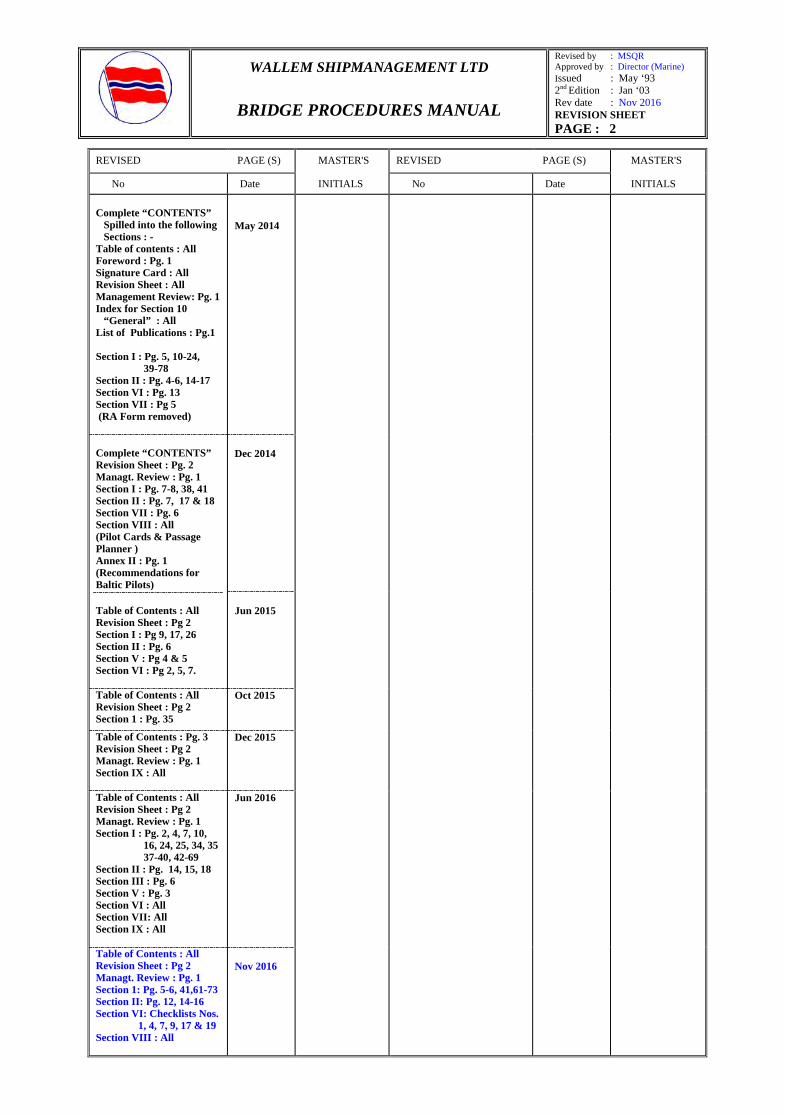
Complete “CONTENTS” Spilled into the following Sections : - Table of contents : All Foreword : Pg. 1 Signature Card : All Revision Sheet : All Management Review: Pg. 1 Index for Section 10 “General” : All List of Publications : Pg.1
Section I : Pg. 5, 10-24, 39-78
Section II : Pg. 4-6, 14-17 Section VI : Pg. 13 Section VII : Pg 5 (RA Form removed)
May 2014
Complete “CONTENTS” Revision Sheet : Pg. 2 Managt. Review : Pg. 1 Section I : Pg. 7-8, 38, 41 Section II : Pg. 7, 17 & 18 Section VII : Pg. 6 Section VIII : All (Pilot Cards & Passage Planner ) Annex II : Pg. 1 (Recommendations for Baltic Pilots)
Table of Contents : All Revision Sheet : Pg 2 Section I : Pg 9, 17, 26 Section II : Pg. 6 Section V : Pg 4 & 5 Section VI : Pg 2, 5, 7.
Dec 2014
Jun 2015
Table of Contents : All Revision Sheet : Pg 2 Section 1 : Pg. 35
Oct 2015
Table of Contents : Pg. 3 Revision Sheet : Pg 2 Managt. Review : Pg. 1 Section IX : All
Dec 2015
Table of Contents : All Revision Sheet : Pg 2 Managt. Review : Pg. 1 Section I : Pg. 2, 4, 7, 10,
16, 24, 25, 34, 35 37-40, 42-69
Section II : Pg. 14, 15, 18 Section III : Pg. 6 Section V : Pg. 3 Section VI : All Section VII: All Section IX : All
Jun 2016
Table of Contents : All Revision Sheet : Pg 2 Managt. Review : Pg. 1 Section 1: Pg. 5-6, 41,61-73 Section II: Pg. 12, 14-16 Section VI: Checklists Nos.
1, 4, 7, 9, 17 & 19 Section VIII : All
Nov 2016
WALLEM SHIPMANAGEMENT LTD
BRIDGE PROCEDURES MANUAL
Revised by : MSQR Approved by : Director (Marine) Issued : May ‘93 2nd Edition : Jan ‘03 Rev date : Nov 2016 MANAGEMENT’S REVIEW PAGE : 1
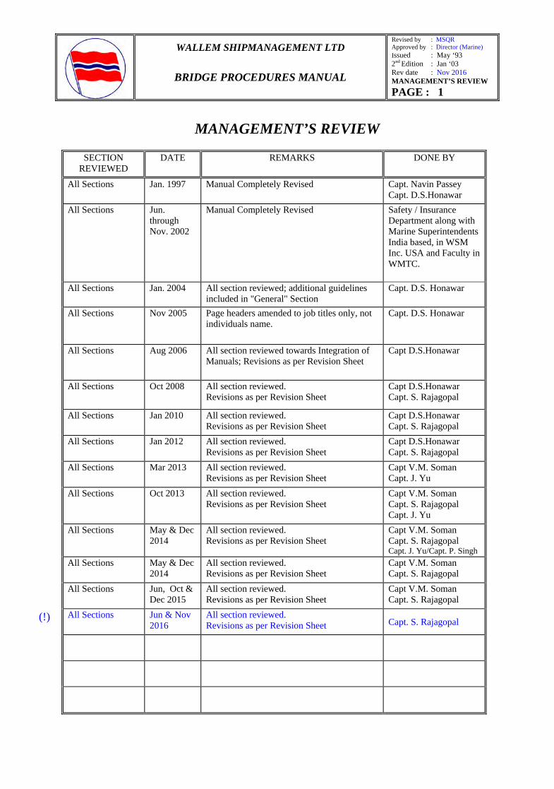
MANAGEMENT’S REVIEW
SECTION REVIEWED
DATE REMARKS DONE BY
All Sections Jan. 1997 Manual Completely Revised Capt. Navin Passey Capt. D.S.Honawar
All Sections Jun. through Nov. 2002
Manual Completely Revised Safety / Insurance Department along with Marine Superintendents India based, in WSM Inc. USA and Faculty in WMTC.
All Sections Jan. 2004 All section reviewed; additional guidelines included in "General" Section
Capt. D.S. Honawar
All Sections Nov 2005 Page headers amended to job titles only, not individuals name.
Capt. D.S. Honawar
All Sections Aug 2006 All section reviewed towards Integration of Manuals; Revisions as per Revision Sheet
Capt D.S.Honawar
All Sections Oct 2008 All section reviewed. Revisions as per Revision Sheet
Capt D.S.Honawar Capt. S. Rajagopal
All Sections Jan 2010 All section reviewed. Revisions as per Revision Sheet
Capt D.S.Honawar Capt. S. Rajagopal
All Sections Jan 2012 All section reviewed. Revisions as per Revision Sheet
Capt D.S.Honawar Capt. S. Rajagopal
All Sections Mar 2013 All section reviewed. Revisions as per Revision Sheet
Capt V.M. Soman Capt. J. Yu
All Sections Oct 2013 All section reviewed. Revisions as per Revision Sheet
Capt V.M. Soman Capt. S. Rajagopal Capt. J. Yu
All Sections May & Dec 2014
All section reviewed. Revisions as per Revision Sheet
Capt V.M. Soman Capt. S. Rajagopal Capt. J. Yu/Capt. P. Singh
All Sections May & Dec 2014
All section reviewed. Revisions as per Revision Sheet
Capt V.M. Soman Capt. S. Rajagopal
All Sections Jun, Oct & Dec 2015
All section reviewed. Revisions as per Revision Sheet
Capt V.M. Soman Capt. S. Rajagopal
All Sections Jun & Nov 2016
All section reviewed. Revisions as per Revision Sheet Capt. S. Rajagopal
(!)
WALLEM SHIPMANAGEMENT LTD
BRIDGE PROCEDURES MANUAL
Revised by : MSQR Approved by : Director (Marine) Issued : May ‘93 2nd Edition : Jan ‘03 Rev date : Nov 2016 SECTION : I PAGE : 5
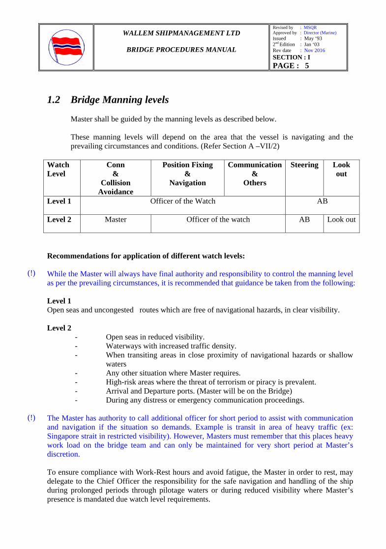
1.2 Bridge Manning levels
Master shall be guided by the manning levels as described below. These manning levels will depend on the area that the vessel is navigating and the prevailing circumstances and conditions. (Refer Section A –VII/2)
Recommendations for application of different watch levels: While the Master will always have final authority and responsibility to control the manning level as per the prevailing circumstances, it is recommended that guidance be taken from the following: Level 1 Open seas and uncongested routes which are free of navigational hazards, in clear visibility. Level 2
- Open seas in reduced visibility. - Waterways with increased traffic density. - When transiting areas in close proximity of navigational hazards or shallow
waters - Any other situation where Master requires. - High-risk areas where the threat of terrorism or piracy is prevalent. - Arrival and Departure ports. (Master will be on the Bridge) - During any distress or emergency communication proceedings.
The Master has authority to call additional officer for short period to assist with communication and navigation if the situation so demands. Example is transit in area of heavy traffic (ex: Singapore strait in restricted visibility). However, Masters must remember that this places heavy work load on the bridge team and can only be maintained for very short period at Master’s discretion. To ensure compliance with Work-Rest hours and avoid fatigue, the Master in order to rest, may delegate to the Chief Officer the responsibility for the safe navigation and handling of the ship during prolonged periods through pilotage waters or during reduced visibility where Master’s presence is mandated due watch level requirements.
Watch Level
Conn &
Collision Avoidance
Position Fixing &
Navigation
Communication &
Others
Steering Look out
Level 1
Officer of the Watch AB
Level 2
Master
Officer of the watch AB Look out
(!)
(!)
WALLEM SHIPMANAGEMENT LTD
BRIDGE PROCEDURES MANUAL
Revised by : MSQR Approved by : Director (Marine) Issued : May ‘93 2nd Edition : Jan ‘03 Rev date : Nov 2016 SECTION : I PAGE : 6
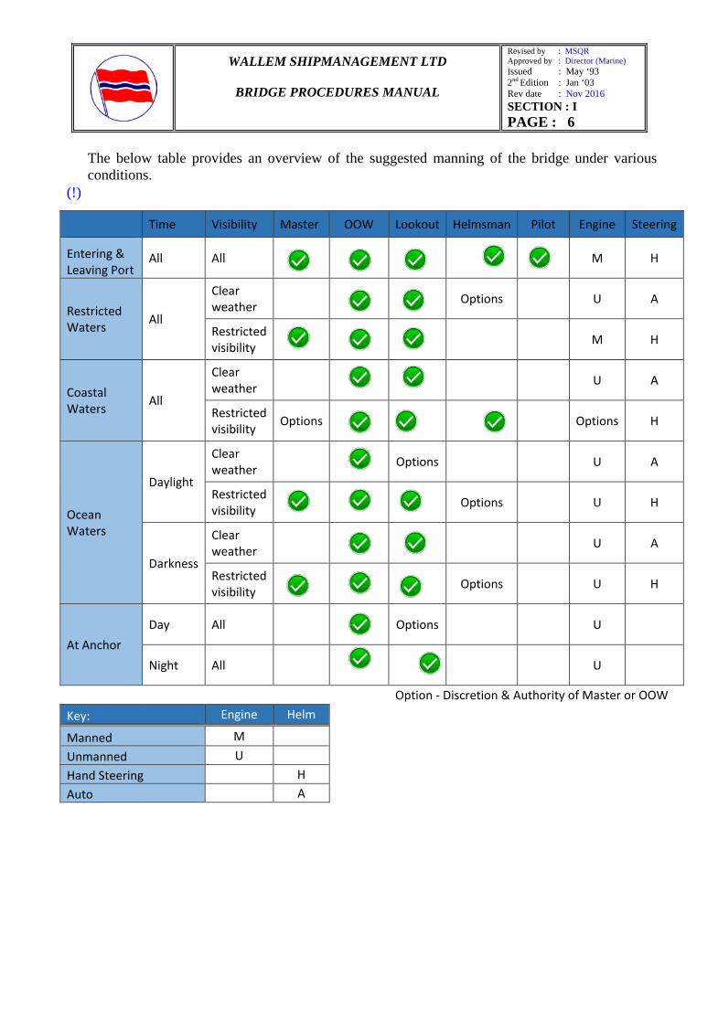
The below table provides an overview of the suggested manning of the bridge under various conditions.
Time Visibility Master OOW Lookout Helmsman Pilot Engine Steering
Entering & Leaving Port
All All
M H
Restricted Waters All
Clear weather
Options U A
Restricted visibility
M H
Coastal Waters All
Clear weather
U A
Restricted visibility Options
Options H
Ocean Waters
Daylight
Clear weather
Options U A
Restricted visibility
Options U H
Darkness
Clear weather
U A
Restricted visibility
Options U H
At Anchor Day All
Options U
Night All
U
Option - Discretion & Authority of Master or OOW
Key: Engine Helm Manned M Unmanned U Hand Steering H Auto A
(!)
WALLEM SHIPMANAGEMENT LTD
BRIDGE PROCEDURES MANUAL
Revised by : MSQR Approved by : Director (Marine) Issued : May ‘93 2nd Edition : Jan ‘03 Rev date : Nov 2016 SECTION : I PAGE : 41
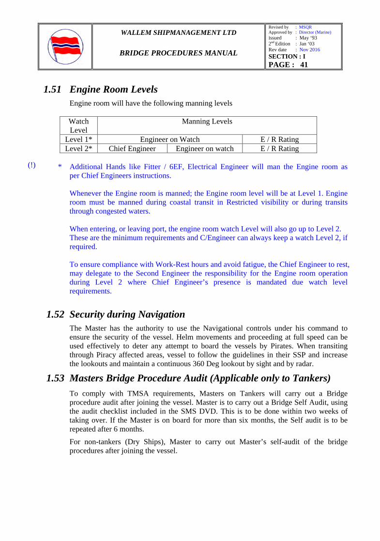
1.51 Engine Room Levels
Engine room will have the following manning levels
Watch Level
Manning Levels
Level 1* Engineer on Watch E / R Rating Level 2* Chief Engineer Engineer on watch E / R Rating
* Additional Hands like Fitter / 6EF, Electrical Engineer will man the Engine room as per Chief Engineers instructions.
Whenever the Engine room is manned; the Engine room level will be at Level 1. Engine room must be manned during coastal transit in Restricted visibility or during transits through congested waters. When entering, or leaving port, the engine room watch Level will also go up to Level 2. These are the minimum requirements and C/Engineer can always keep a watch Level 2, if required. To ensure compliance with Work-Rest hours and avoid fatigue, the Chief Engineer to rest, may delegate to the Second Engineer the responsibility for the Engine room operation during Level 2 where Chief Engineer’s presence is mandated due watch level requirements.
1.52 Security during Navigation
The Master has the authority to use the Navigational controls under his command to ensure the security of the vessel. Helm movements and proceeding at full speed can be used effectively to deter any attempt to board the vessels by Pirates. When transiting through Piracy affected areas, vessel to follow the guidelines in their SSP and increase the lookouts and maintain a continuous 360 Deg lookout by sight and by radar.
1.53 Masters Bridge Procedure Audit (Applicable only to Tankers)
To comply with TMSA requirements, Masters on Tankers will carry out a Bridge procedure audit after joining the vessel. Master is to carry out a Bridge Self Audit, using the audit checklist included in the SMS DVD. This is to be done within two weeks of taking over. If the Master is on board for more than six months, the Self audit is to be repeated after 6 months.
For non-tankers (Dry Ships), Master to carry out Master’s self-audit of the bridge procedures after joining the vessel.
(!)

WALLEM SHIPMANAGEMENT LTD
BRIDGE PROCEDURES MANUAL
Revised by : MSQR Approved by : Director (Marine) Issued : May ‘93 2nd Edition : Jan ‘03 Rev date : Nov 2016 SECTION : I PAGE : 61
Minimum settings for Cross Track Limits are mentioned in section 1.58.17
Coastal and Confined Waters Definitions (for ECDIS related settings) COASTAL WATERS CONFINED WATERS
Areas where vessel is navigating with 20 miles from the coast line, or within 30 minutes of sailing time from the grounding line (draft) whichever is lesser. However, above mentioned margins may be made more stringent as per discretion of Master considering below mentioned points:
a) Distance off the coastline for safe navigation.
b) Traffic Separation Scheme according to IMO.
c) Relationship between the depth or water and the ship’s draft.
d) Navigable area in an archipelago. e) The state of congestion at the area to
be navigated. f) Any other factor.
Harbors, ports, under pilotage or waters where special caution is judged to be required because of unavailability of adequate sea room, when factors are taken into account such as length, width, draft and maneuverability of the ship, the depth of navigable sea area, topographical characteristics, weather and sea conditions
e) Wheel Over Point (W/O) – The wheel over point (W/O) for altering courses is calculated automatically by the ECDIS depending on the Ship’s Parameters in the ECDIS & Route Parameters entered by the user (i.e. speed, turn radius, ROT). The W/O point is marked on the route automatically as well.
1.58.12.7 SAFETY DEPTH & CONTOUR Setting or defining waters which are safely navigable for the vessel is an important part of the route planning and monitoring.
Failure to define the safe water appropriately in the ECDIS poses a significant risk to the safety of navigation using this equipment. Defining of safe waters includes setting of the following:
- Safety Contour - Safety Depth - Shallow Contour - Deep Contour
Safety Depth: This is the value set by the mariner that is used by ECDIS to portray soundings as black if they are equal to or shoaler than the value and gray if they are deeper. Safety Contour: A specific depth contour set by ECDIS. It demarks the boundary between “Safe Water” and shallow water with an extra wide isoline and is used to give an alarm if the ship, within a time specified by the mariner, is going to cross the safety contour Make an appropriate sticker and post conspicuously on The ECDIS having the following content:
(!)

WALLEM SHIPMANAGEMENT LTD
BRIDGE PROCEDURES MANUAL
Revised by : MSQR Approved by : Director (Marine) Issued : May ‘93 2nd Edition : Jan ‘03 Rev date : Nov 2016 SECTION : I PAGE : 62
Delineate the SENC for shallow, safety and deep contour values for the intended passage, considering the vessel’s maximum draft in relation to the available depth of water. It is recommended to select these contour values as follows: Shallow Contour = Maximum Static draft Safety Contour = Dynamic draft + 10% or 20% depending upon type of passage (i.e. Port approaches or Coastal passages as per company's UKC policy) Safety Contour = Safety Depth (Recommended) (Note: For the sake of simplicity and safety, it is recommended to use same value for Safety Depth and Safety Contour. The Safety Contour shall NOT be less than Safety Depth; Safety Contour can be set higher than Safety Depth as per Master’s discretion. It is important to note some equipment do not allow different values for “Safety Contour” and “Safety Depth”) Deep Contour = Twice the maximum Static draft All the bridge team should be made aware of this depth requirements and compliance with the recommended guidelines.
1.58.12.8 Creating a Route After all settings have been done, actual route creation in ECDIS has to be done. Following should be noted while creating route:
a) Route can be created by either retrieving older route from the database or entering waypoints or by plotting waypoints manually on the ENCs. (Caution to be exercised when retrieving old routes with due regard to any changes in vessel’s condition, i.e. laden or in ballast condition and any other factors which has a bearing on route planning)
b) Depending on the situation, it is best to always use a previous route in the ECDIS with common waypoints and parameters.
c) User can choose to make the route in a Rhumb Line (RL) or Great Circle (GC). If creating a GC route, a rough GC route can be created first with selection in the table of waypoint as GC and then altering intermediate waypoints as necessary.
d) Be aware of the settings on the ECDIS. Special attention to be paid to each leg’s respective factors such as Turn Radius, Rate of Turn, Planned Speed and cross track limits. All legs may not have the same speed, Turn radius, ROT, Safe water settings etc.
1.58.12.9 Creating Limiting Danger Lines, Notes and Markings on the Charts
a) A comprehensive passage plan requires inclusion of detailed markings on the appropriate charts (Paper and Electronic) as well as listed in the passage plan.
WALLEM SHIPMANAGEMENT LTD
BRIDGE PROCEDURES MANUAL
Revised by : MSQR Approved by : Director (Marine) Issued : May ‘93 2nd Edition : Jan ‘03 Rev date : Nov 2016 SECTION : I PAGE : 63
b) The principles of markings on the ENC/RNC shall be based on the traditional markings on the paper charts. Master’s Instructions, Standing orders, Procedures as per company’s Bridge Procedures manual, VIQ requirements, Industry practices etc. should be consulted during markings required for passage planning.
c) Following additional markings, but not limited to should be done on the ENC/RNC as compared to traditional marking procedure:
- Change over points from ENC to RNC (RCDS Mode) and vice versa. - Change in Safe Water Settings - Limiting Danger Lines i.e. No Go Areas, for depths less than or equal to Safety Depth,
Parallel Indexing, clearing bearings etc. - Marking isolated danger marks inside the Safety Contours. - Others as required.
1.58.12.10 Route Checking/ Validating Once a route has been planned on ECDIS, this route shall be validated/verified by the Master before finally approving the entire passage plan. Only a completely validated route to be used for navigation. Validation/Verification of a route plan is an automatic function available on ECDIS for checking if any safety values (as set by user) are breached or if the route takes the vessel along any dangerous conditions. This function reveals a wide range of dangers along the vessel’s intended route. Any such dangers, if revealed during validation, shall be rectified by amending the route plan, till all dangers are removed and a completely validated route is available. For the purpose of validating a route on ECDIS, in addition to passage planning confirmation as per Bridge Procedures Manual, Master shall be guided by following:
a) Route on RNC cannot be checked using this procedure and shall be manually verified. b) Route shall be plotted on both ECDIS (For vessels which are fitted up with back up ECDIS). c) The validation check shall be carried out giving due consideration to the various settings on
the ECDIS. d) Cross Track Limits – Route Checking/ validation checks for dangers on the course as well as
area within the defined off track limits. e) Safety depth – Comply with Company’s UKC policy, the applicable UKC for each leg shall
be confirmed. f) In case route validating function on ECDIS does not have feature for multiple safety depth
settings for validation, the strictest requirement (largest UKC) shall be confirmed. g) In case violations for largest UKC requirement are noted for areas where this UKC is not
applicable then after one complete validation, the value of safety depth shall be changed for applicable UKC (e.g. Ocean Areas, Coastal or port approaches) and then revalidated.
h) The route shall be checked against any grounding alarms and if the route is passing over / intercepting any limiting danger lines, critical points, warnings etc as created by the user.
WALLEM SHIPMANAGEMENT LTD
BRIDGE PROCEDURES MANUAL
Revised by : MSQR Approved by : Director (Marine) Issued : May ‘93 2nd Edition : Jan ‘03 Rev date : Nov 2016 SECTION : I PAGE : 64
i) The route shall be checked against limits and special requirements where special conditions exists e.g. PSSA, ECAs, Special Areas etc)
j) Geometry of Alteration of courses (e.g. large alterations may not be possible in short distance/turn radius not practical/ impossible turn etc.)
k) Actions to be taken if dangers are detected. There are two ways of dealing with it – amend the waypoint to pass clear of the specified danger or reduce the cross track limit in case of insufficient sea room to amend the waypoints. Distance from danger should be sufficient to alert and take timely action.
l) Any changes to route or to route parameters will need rechecking of the route to make sure that the new amendment has not jeopardized the safety of vessel.
m) After validation is completed on one ECDIS and all alarms addressed, the route shall be revalidated on the second ECDIS independently.
n) The route should be verified manually even though the ECDIS has validated the route. Manually verifying the route will involve going to the largest scale chart and on the appropriate scale and scrolling the chart to check the entire route visually.
1.58.12.11 Route Plan – Back up Any abnormalities or failure may directly result in losing all data from the ECDIS. It is particularly an important aspect of planning on ECDIS to save route and passage plans regularly and maintain a good database in a separate computer. 1.58.12.12 Alternate Route Planning Alternate Route Planning is a procedure where the user copy (called as “Alternate Route”) of the monitored route without disturbing the monitoring mode. This is to facilitate the need to amend the route for various reasons e.g. change of voyage instructions, weather routing, navigational warnings etc. The monitored route and the “Alternate Route” are displayed simultaneously. Once edited, the “Alternate Route” can be checked/validated and then exchanged with monitoring route. By doing this, the vessel will never come out of the monitoring mode. Log entry pertaining to this should be made in the deck log book. 1.58.13 Route Monitoring After planning and validation of route is completed, route should be monitored using ECDIS for the purpose of safe navigation based on the input of Route Parameters and Safe water Settings. Following are key points to note with regard to Route Monitoring on ECDIS:
a) Route monitoring shall be done on both ECDIS (for vessels fitted with Back up ECDIS).
WALLEM SHIPMANAGEMENT LTD
BRIDGE PROCEDURES MANUAL
Revised by : MSQR Approved by : Director (Marine) Issued : May ‘93 2nd Edition : Jan ‘03 Rev date : Nov 2016 SECTION : I PAGE : 65
b) Over reliance on the automatic route monitoring should not be exercised during real time navigation and basic watch keeping practices and procedures in accordance with “Bridge Procedures Manual”, industry practices and COLREGS should be complied with.
c) No route to be changed over to “Monitoring Mode” unless checked, validated and manually verified by the Master.
d) In order to monitor limiting danger lines/ Markings on the ENCs these should be additionally activated for the purpose of alarms/alerts during route monitoring. Failure to do this will not trigger alarm if vessel is running into areas / lines marked that requires OOW’s attention.
e) In brief Route Monitoring involves: - Setting for Monitoring. - Activating the Route Plan (Putting the route in Monitoring Mode) - Navigation on Monitored Route (Execution of Voyage) - Voyage Recording/ Playback
1.58.13.1 Settings for Route Monitoring
a) Date & Time Settings: The date and time settings of ECDIS computer should be correctly set, compared and updated if required. These settings may affect display of some “time” based chart information, updates (e.g. firing practices, MIO etc) and also the voyage recording time.
b) Sensor Settings on ECDIS: The sensors connected to ECDIS should be checked for
accuracy and selected appropriately. The officer in charge should always select the most preferred sensor source with regards to Heading, Depth, Speed, Radar, ARPA, AIS. In case of any failure of sensors, the most accurate secondary sensor should be selected. If no secondary sensor is available, then a manual input should be entered. Following is the guidance for position fixing sensor settings / configuration for ECDIS which should be used as reference for configuring other multiple sensors:
- Position information in ECDIS is based on Primary Position Source. ECDIS also allows for Secondary Position Source and manual input.
- The principle is such that in case of the Primary Position Source failure, the Secondary Position Source should be used and in case of failure of Secondary Position Source, manual input can be used.
- Failure of one GPS should not render Primary Position Source failure on both ECDIS, hence following settings are recommended for vessel’s fitted with two GPS: ECDIS 1: Primary Position Source (GPS 1) & Secondary Position Source (GPS 2) ECDIS 2: Primary Position Source (GPS 2) and Secondary Position Source (GPS 1)
c) Display Configuration and Scale of ENCs: The most appropriate display and orientation for situational awareness should be selected. Day/Night mode to be selected as required.
WALLEM SHIPMANAGEMENT LTD
BRIDGE PROCEDURES MANUAL
Revised by : MSQR Approved by : Director (Marine) Issued : May ‘93 2nd Edition : Jan ‘03 Rev date : Nov 2016 SECTION : I PAGE : 66
It is the responsibility of the OOW to make sure that most optimum scale is used for navigation considering at least but not limited to the following:
- Navigation Usage Band - Largest scale ENC available - SCAMIN not affecting chart display
d) ENC Layers: Chart settings will include selecting correct display category i.e Base, Standard
and Other. All layers of Standard Display Category should be kept “ON” this is an IMO requirement. Appropriate other layers should be selected for monitoring the route.
e) Look Ahead: This is a provision for predicted movement of the vessel. It is intended for generation of Anti-Grounding Alarms, Alerts and navigational Alarms thus increasing the situational awareness of the OOW in proximity of dangers around the vessel.
In particular the ECDIS will trigger a Look Ahead alert within the time frame for distance, which is pre-set by the user, if the frame crosses a Safety Contour, passes too close to an ENC object and crosses the boundaries of an area as selected by the user. Although some manufacturers may allow flexibility of setting look ahead as “Distance” or ‘Time” based setting, it should be set as “Time” based value. This makes it dynamic in relation to the speed of the vessel unlike if kept as a “Distance” when it remains static irrespective of speed.
1.58.14 ECDIS Operation in Non AVCS areas
For Vessels on paperless navigation or using ECDIS as a primary means of navigation, following procedures would apply in areas where there is no ENC Coverage
• Master shall order paper charts of the largest scale. Charts shall be fully corrected and updated.
• The passage plan shall be drawn on the paper charts and courses shall be laid right till the berth including frequency of position fixing, abort points, no go areas and other pertinent information
• Vessel would operate in this area and take all measures as would a vessel on paper chart and as detailed in this manual.
1.58.15 Safety Contours and their application
Safety Depth is one of the great advantages of the system. The system displays clearly in bold the contour beyond which you shall not proceed. Further, the safety frame will alarm when in contact with the Safety Contour, thereby giving warning of the proximity of danger. However, the lack of contour data currently available within ENCs means that the Safety Contour and Safety Depth are not fully harmonized. Areas that are deeper than the safety contour will have a grey or white background in the normal daytime viewing mode, depending whether in two or four colour depth area indication settings. If the
(!!) (!)
WALLEM SHIPMANAGEMENT LTD
BRIDGE PROCEDURES MANUAL
Revised by : MSQR Approved by : Director (Marine) Issued : May ‘93 2nd Edition : Jan ‘03 Rev date : Nov 2016 SECTION : I PAGE : 67
Safety Depth value is set to 12 m, for example, the system will automatically highlight the next available contour, which maybe 15 m or higher. This would result in the vessel passing over soundings greater than 12 Mtrs but less than 15 m or the avilable contour. Vessels shall use the Limiting Danger Line (LDL) or equivalent (some models use different name like warning line) in such situation. LDL is a manually inserted danger line that will alarm when the safety frame touches it, and is an ideal solution. The limiting Danger line (Alarmed) needs to be used on all the safety depth contours as the "NO GO Areas".
When the Safety Depth value is inserted, all soundings equal to or less than this value are highlighted in bold, highlighting the potentially unsafe areas.
A manual danger line can be drawn around the soundings to produce the LDL or warning line by using Manual Corrections or equivalent function and making it alarmable by assigning a danger attribute. The safety value is a prime consideration and must be large enough to consider the quality of data. Because the contour is being drawn manually, the inaccuracy of the data in use to be considered. Note that the LDL is time dependent because it is based upon the height of tide and that when no longer required it must be ensured that the Safety Contour is reverted
1.58.16 Additional Master pilot information exchange
Following additional points to be discussed during the Master Pilot Exchang for paperless ship and ships with ECDIS as primary means for navigation • Route agreed with waypoints and courses marked on the ENCs and additional
information marked on the chart as applicable • Safety contour/safety depth setting confirmed • Safety frame settings and Alarms “ON “ • Emergency or standby anchorage areas marked on the ENC
Any amendment to the Safety frame must be thoroughly discussed and assessed with the pilot prior to implementation.
1.58.17 Management and setting of Alarms
With ECDIS, navigators must recognise the level of display and the objects to display for the optimum navigational information for any situation. It is essential that the Masters, navigating officers are aware of the benefits of managing the chart display, safety settings, and alarm system of ECDIS. Improper management of the system may result in the anti-grounding alarms and other indications failing to activate as required for safe conduct of the navigation. The appearance and content of the chart data displayed on ECDIS may change significantly from different settings as the display is generated as per the specifications characterised by the IHO (International Hydrographic Office) Presentation Library (S-52). The Safety Frame or equivalent (some manufacturer term them as danger detection vector and danger detection sector) provides warning of dangers/cautions. The value of the safety frame or equivalent must be altered per the prevailing circumstances to
(!!)
(!)
WALLEM SHIPMANAGEMENT LTD
BRIDGE PROCEDURES MANUAL
Revised by : MSQR Approved by : Director (Marine) Issued : May ‘93 2nd Edition : Jan ‘03 Rev date : Nov 2016 SECTION : I PAGE : 68
prevent unnecessary alarms and to ensure that adequate warning is given. Early warning features /alarms at time may become so frequent due nature of fairways pilotage water etc that it becomes a huge distraction for staff/pilots conning the vessel. Hence, the safety frame or equivalent shall be set in a seamanship like manner, i.e. with a sensible time or range warning depending on proximity to hazards and planned speed. It is recommended to set the safety frame or guard zone “As large as possible as the circumstances allow”. The following are the MINIMUM settings which shall be used : 1. Safety Frame:
Pilotage and Confined Waters - Ahead: 6 mins ; Port: 0.1 nm; Starboard: 0.1 nm Coastal Waters - Ahead: 12 mins ; Port: 0.2 nm ; Starboard: 0.2 nm Open Seas (Ocean) - Ahead: 15 mins ; Port: 0.5 nm ; Starboard: 0.5 nm
2. Waypoint Approach = as calculated for each alteration 3. Off course = 10 Deg 4. Cross Track Error (XTE):
Pilotage and Confined Waters - 0.1 NM based on width of channel Coastal Waters - 0.50 NM Open Seas - 1.0 NM
It is of utmost importance that the Navigational Watchkeeping Officer is fully familiar with all the Alarms and Warnings which have been activated. A handover checklist of the alarms and warnings should be completed before taking over the watch. Prior taking over the watch, it is essential to note down what warnings / alarms are already in place.
1.58.18 CATZOC (Category of Zone of Confidence)
When the IHO developed the S-57 standard this situation was recognized and the quality of survey data used to compile ENCs had to be encoded within a composite data quality indicator ‘Category of Zone of Confidence’ (CATZOC) The ZOC category allocated indicates that particular ENC data meets minimum criteria for position and depth accuracy. This can be looked upon as the survey accuracy. six category levels –A1, A2, B, C, D, and U (data not assessed). It is important that the user knows the ZOC for the area covered for the voyage as it clearly affects the voyage planning and voyage monitoring. Hence the officer when making a planning a passage needs to have the ZOC layer “ON”
(!!)
WALLEM SHIPMANAGEMENT LTD
BRIDGE PROCEDURES MANUAL
Revised by : MSQR Approved by : Director (Marine) Issued : May ‘93 2nd Edition : Jan ‘03 Rev date : Nov 2016 SECTION : I PAGE : 69
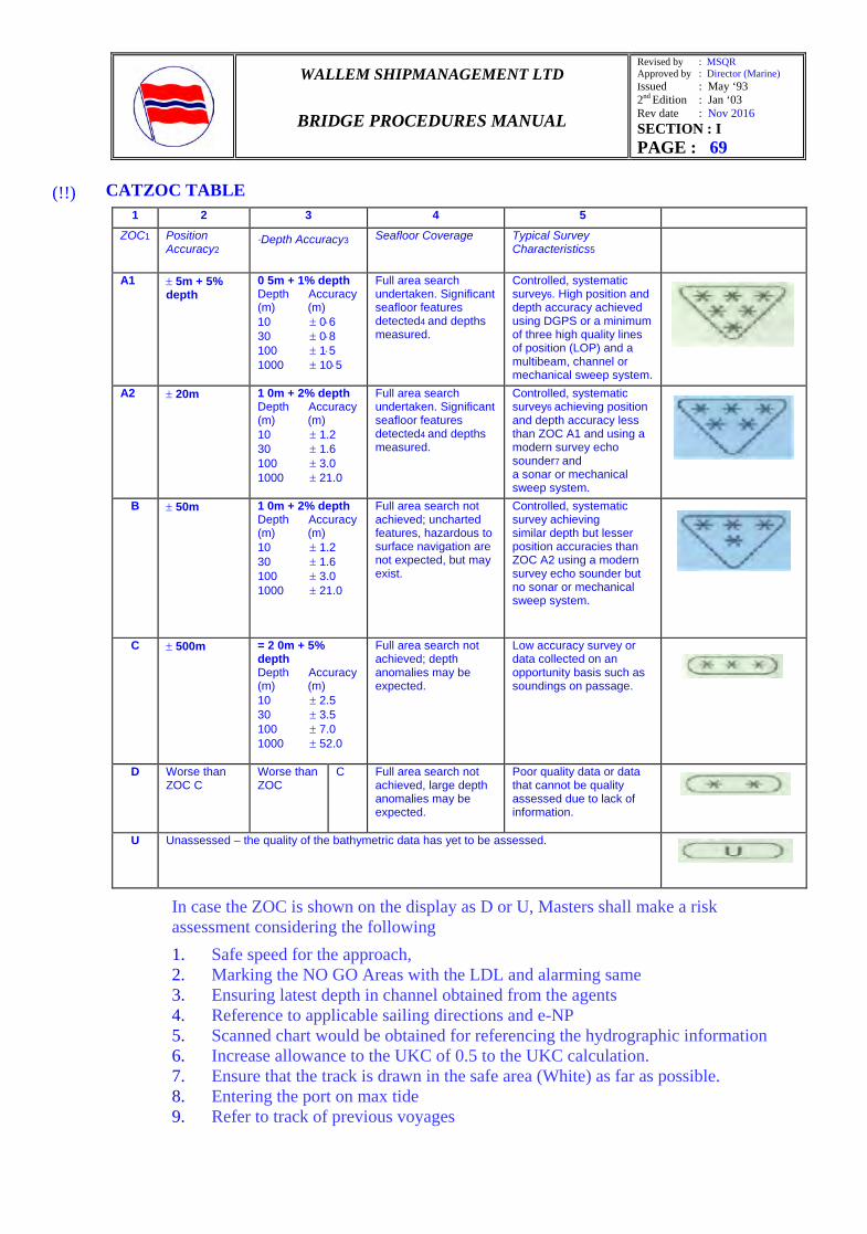
CATZOC TABLE 1 2 3 4 5
ZOC1 Position Accuracy2
·Depth Accuracy3 Seafloor Coverage Typical Survey Characteristics5
A1 ± 5m + 5% depth
0 5m + 1% depth Depth Accuracy (m) (m) 10 ± 0⋅6 30 ± 0⋅8 100 ± 1⋅5 1000 ± 10⋅5
Full area search undertaken. Significant seafloor features detected4 and depths measured.
Controlled, systematic survey6. High position and depth accuracy achieved using DGPS or a minimum of three high quality lines of position (LOP) and a multibeam, channel or mechanical sweep system.
A2 ± 20m 1 0m + 2% depth Depth Accuracy (m) (m) 10 ± 1.2 30 ± 1.6 100 ± 3.0 1000 ± 21.0
Full area search undertaken. Significant seafloor features detected4 and depths measured.
Controlled, systematic survey6 achieving position and depth accuracy less than ZOC A1 and using a modern survey echo sounder7 and a sonar or mechanical sweep system.
B ± 50m 1 0m + 2% depth Depth Accuracy (m) (m) 10 ± 1.2 30 ± 1.6 100 ± 3.0 1000 ± 21.0
Full area search not achieved; uncharted features, hazardous to surface navigation are not expected, but may exist.
Controlled, systematic survey achieving similar depth but lesser position accuracies than ZOC A2 using a modern survey echo sounder but no sonar or mechanical sweep system.
C ± 500m = 2 0m + 5% depth Depth Accuracy (m) (m) 10 ± 2.5 30 ± 3.5 100 ± 7.0 1000 ± 52.0
Full area search not achieved; depth anomalies may be expected.
Low accuracy survey or data collected on an opportunity basis such as soundings on passage.
D Worse than ZOC C
Worse than ZOC
C Full area search not achieved, large depth anomalies may be expected.
Poor quality data or data that cannot be quality assessed due to lack of information.
U Unassessed – the quality of the bathymetric data has yet to be assessed.
In case the ZOC is shown on the display as D or U, Masters shall make a risk assessment considering the following 1. Safe speed for the approach, 2. Marking the NO GO Areas with the LDL and alarming same 3. Ensuring latest depth in channel obtained from the agents 4. Reference to applicable sailing directions and e-NP 5. Scanned chart would be obtained for referencing the hydrographic information 6. Increase allowance to the UKC of 0.5 to the UKC calculation. 7. Ensure that the track is drawn in the safe area (White) as far as possible. 8. Entering the port on max tide 9. Refer to track of previous voyages
(!!)

WALLEM SHIPMANAGEMENT LTD
BRIDGE PROCEDURES MANUAL
Revised by : MSQR Approved by : Director (Marine) Issued : May ‘93 2nd Edition : Jan ‘03 Rev date : Nov 2016 SECTION : I PAGE : 70
For other CATZOC areas, Vessel will allow UKC between 0.1 and 0.4 as applicable.
If the vessel’s cargo carriage is affected due to the additional UKC allowance for CATZOC D or U, Master shall immediately contact the Marine Superintendent with a risk assessment for the transit considering the previous transit in same area. If the vessel has transited the same channel or courses by the same vessel or other vessels in the fleet, the Marine superintendent would grant an exemption "for the additional UKC allowance for CATZOC" Based on the risk assessment. Master would review risk assessment and discuss with pilot (during Master pilot information exchange) and then carry out the transit. If there are no previous voyages for reference, the Master would inform the commercial operator of the reduced cargo carriage after discussion with the Marine Superintendent. Master shall also keep echo sounder running during the transit to obtain the actual depths in the channel.
1.58.19 Action in case of a Breakdown of one ECDIS:
Any vessel operating paperless which has a breakdown of one ECDIS should inform the office to obtain a dispensation from the Flag State. The ECDIS Checklist No.5 to be complied with.
1.58.20 Testing of ECDIS from emergency source of power:
This is with reference to testing of ECDIS from an Emergency source of power. Please kindly be advised as per SOLAS Ch.2-1, Regulation 43.2.4 - It should be possible to operate ECDIS and all equipments for its normal functioning when supplied by an emergency source of electrical power. - Changing from one source of power supply to another or any interruption of the supply for a period of 45 seconds, should not require the equipment to be manually re-initialized. As per this requirement, please try out both the ECDIS fitted onboard from the Emergency power source and confirm the results. Please carry out the test giving due regard to safety of navigation. It is recommended to plan and carry out the test when the vessel is alongside berth or whilst at Anchorage.
1.58.21 ECDIS Voyage Records ECDIS voyage records should be downloaded and maintained on board for period of 1 year on board the vessel and portable drive can be used for storing the voyage data files
1.58.22 ECDIS Anomalies The international Hydrographic Organization (IHO) has produced ECDIS Data Presentation and Performance Check that are designed to alert watchkeeping officers to the possibility that the installed ECDIS software may require an update from the manufacturer.. ECDIS data presentation and performance checks are conducted following a software update, ECDIS upgrade or at any time when the Master or watchkeeping officers have concerns over the performance of the ECDIS on board. Any occurrence of apparently new or known, but insufficiently addressed, anomalies is
WALLEM SHIPMANAGEMENT LTD
BRIDGE PROCEDURES MANUAL
Revised by : MSQR Approved by : Director (Marine) Issued : May ‘93 2nd Edition : Jan ‘03 Rev date : Nov 2016 SECTION : I PAGE : 71
reported directly to Fleet Cell for further follow up with relevant manufacture & the IHO.
1.58.23 IMPACT ON ECDIS DUE TO OTHER EMERGENCIES
In case of failure of ECDIS is due to other machinery troubles e.g. Black out will result in ECDIS functioning properly for certain period of time till back up power is available. Bridge team members should make best use of the resources to ensure ECDIS are available for maximum period and following should be considered as appropriate to the circumstances in consultation with the company. a) Inter-switching one ECDIS on UPS and keeping the other Off/Standby and then switching over to the other ECDIS subsequently.
b) Taking snapshots of ENCs (and printout) for reference in case needed later.
c) Obtaining scanned copies of charts for immediate use from the company.
1.58.24 Anti Virus Protection for ECDIS
Anti-virus protection for ECDIS is very important. WIS (IT Division of Wallem) provides the anti-virus program and also the updates. These are to be loaded on all computers on board. The USB for transferring data from the E-Mail computer to the ECDIS must be a dedicated USB and not used for any other purpose. It must be marked accordingly and kept in the custody of the Navigational officer.
RISK REDUCTION MEASURES
In order to respond to ECDIS failures or malfunctions, Masters to be guided by one or more of the following to avoid any immediate impact to the safe navigation in case of sudden ECDIS abnormalities, malfunctions or failures:- a) Doing mapping on Radars b) Input of waypoints and cross track limits in GPS. c) Carriage of suitable number of small scale charts or arrangement for immediate
supply of scanned charts (for emergency use only) such that vessel can be navigated to a safe place (e.g. anchoring / arranging for repairs etc.)
d) Having ECDIS software installed on laptop with long battery life (and/or spare batteries or even having a hand operated dynamo serving as additional power source).
(!!)

WALLEM SHIPMANAGEMENT LTD
BRIDGE PROCEDURES MANUAL
Revised by : MSQR Approved by : Director (Marine) Issued : May ‘93 2nd Edition : Jan ‘03 Rev date : Nov 2016 SECTION : I PAGE : 72
CARRIAGE OF PAPER CHARTS ONBOARD VESSELS EQUIPPED WITH ECDIS
As per SEQ Certificate
Paper Chart Carriage Standard
Remarks
Primary Back Up
ECDIS
ECDIS
At least carry an appropriate folio of paper nautical charts for regions and areas where no ENCs are available i.e. for areas where RNCs are used and/or RCDS mode is used, the vessel shall carry the equivalent paper nautical chart
Additionally, subject to Master’s discretion, vessel to carry suitable number of small scale charts for emergency use. Such folio of paper charts for emergency use to be managed and kept updated.
ECDIS Paper Carry full folio of paper charts as applicable. These charts to be managed and kept updated.
Note: If flag state, or any other similar regulations, requires additional carriage requirements than described above, then those additional requirements have to be complied in addition to this standard.
Conclusion:
• ECDIS provides a number of functions and features to make navigation safe and efficient.
• It has the capability to make navigation easier and reduce the burden on the ship’s officers.
• There is however a potential for errors to creep in, which are likely to be of a different nature compared to paper charts.
• The tendency to put too much trust on the display without understanding the scope and limitations of the functions should be avoided.
• Training in the use and operation of ECDIS is both essential and mandatory. • An untrained operator can induce errors into the system which, if left undetected, can
lead to disastrous consequences. • At the end of the day, the ECDIS is still an electronic aid to navigation, albeit a powerful
one. It cannot be a replacement for good seamanship and prudent navigational practices.

WALLEM SHIPMANAGEMENT LTD
BRIDGE PROCEDURES MANUAL
Revised by : MSQR Approved by : Director (Marine) Issued : May ‘93 2nd Edition : Jan ‘03 Rev date : Nov 2016 SECTION : I PAGE : 73
Abbreviations: ADC Admiralty Digital catalogue AIO Admiralty Information Overlay ARCS Admiralty Raster Chart Services AVCS Admiralty Vector Chart Services CATZOC Category of Zone of Confidence EBL Electronic Bearing Line ECDIS Electronic Chart Display and Information System ECS Electronic Chart System ENC Electronic Navigational Chart GC Great Circle IHO International Hydrographic Office MIO Marine Information Object NTM Notices to Mariners RCDS Raster Chart Display System RENC Regional Electronic Navigation Chart Co-ordinating Centre RIO Radar Information Overlay RL Rhumb Line RNC Raster Navigational Chart ROT Rate of Turn SCAMIN Scale Minimum SENC Systems Electronic Navigational Chart SRNC System Raster Navigational Chart Database UPS Uninterrupted Power Supply VAR Value Added Reseller W/O, WOP Wheel Over Point WEND World-wide Electronic Navigational Chart Database WGS World Geodetic System WP Waypoint WWNWS World-wide Navigational Warning System XTE Cross Track Error
WALLEM SHIPMANAGEMENT LTD
BRIDGE PROCEDURES MANUAL
Revised by : MSQR Approved by : Director (Marine) Issued : May ‘93 2nd Edition : Jan ‘03 Rev date : Nov 2016 SECTION : II PAGE : 12
2.10 UNDER KEEL CLEARANCE (UKC) Application
These guide lines apply to all vessels.
Allowance for variable factors affecting UKC
The under keel allowance necessary for safe bottom clearance varies with local conditions and the size and handling characteristics of the ship. The allowance consists of two main elements: A minimum Under Keel Clearance (UKC) which must be maintained between the
ship and the bottom.
An allowance for the other variable factors that may be present.
Under keel clearance can be affected by several factors and the under keel calculations should include, but not necessarily be limited to;
The predicted height of the tide;
Changes in the predicted tidal height, which are caused by wind speed and direction and
high or low barometric pressure;
Nature and stability of the bottom – i.e. sand waves, siltation etc.;
Accuracy of hydrographic data, (References to reliability is often included on charts);
Change of water density and the increase in draught due to fresh water allowance;
The vessel’s size and handling characteristics and increase in draught due to heel;
Wave response allowance, which is the vertical displacement of the hull due to heave,
roll and pitch motions;
The reliability of draft observations and calculations, including estimates of hogging and
sagging;
Reduced depths over pipelines and other obstructions.
(!)
(!)
WALLEM SHIPMANAGEMENT LTD
BRIDGE PROCEDURES MANUAL
Revised by : MSQR Approved by : Director (Marine) Issued : May ‘93 2nd Edition : Jan ‘03 Rev date : Nov 2016 SECTION : II PAGE : 14
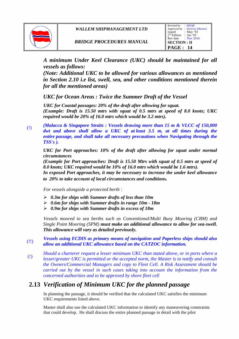
A minimum Under Keel Clearance (UKC) should be maintained for all vessels as follows:
(Note: Additional UKC to be allowed for various allowances as mentioned in Section 2.10 i.e list, swell, sea, and other conditions mentioned therein for all the mentioned areas)
UKC for Ocean Areas : Twice the Summer Draft of the Vessel
UKC for Coastal passages: 20% of the draft after allowing for squat. (Example: Draft is 15.50 mtrs with squat of 0.5 mtrs at speed of 8.0 knots; UKC
required would be 20% of 16.0 mtrs which would be 3.2 mtrs).
(Malacca & Singapore Straits : Vessels drawing more than 15 m & VLCC of 150,000 dwt and above shall allow a UKC of at least 3.5 m, at all times during the entire passage, and shall take all necessary precautions when Navigating through the TSS's ).
UKC for Port approaches: 10% of the draft after allowing for squat under normal circumstances
(Example for Port approaches: Draft is 15.50 Mtrs with squat of 0.5 mtrs at speed of 8.0 knots; UKC required would be 10% of 16.0 mtrs which would be 1.6 mtrs). In exposed Port approaches, it may be necessary to increase the under keel allowance to 20% to take account of local circumstances and conditions.
For vessels alongside a protected berth :
0.3m for ships with Summer drafts of less than 10m 0.6m for ships with Summer drafts in range 10m - 18m 0.9m for ships with Summer drafts in excess of 18m
Vessels moored to sea berths such as Conventional/Multi Buoy Mooring (CBM) and Single Point Mooring (SPM) must make an additional allowance to allow for sea-swell. This allowance will vary as detailed previously.
Vessels using ECDIS as primary means of navigation and Paperless ships should also allow an additional UKC allowance based on the CATZOC information.
Should a charterer request a lesser minimum UKC than stated above, or in ports where a lesser/greater UKC is permitted or the accepted norm, the Master is to notify and consult the Owners/Commercial Managers and copy to Fleet Cell. A Risk Assessment should be carried out by the vessel in such cases taking into account the information from the concerned authorities and to be approved by shore fleet cell
2.13 Verification of Minimum UKC for the planned passage
In planning the passage, it should be verified that the calculated UKC satisfies the minimum UKC requirements listed above.
Master shall also use the calculated UKC information to identify any maneuvering constraints that could develop. He shall discuss the entire planned passage in detail with the pilot
(!)
(!!)
(!)
WALLEM SHIPMANAGEMENT LTD
BRIDGE PROCEDURES MANUAL
Revised by : MSQR Approved by : Director (Marine) Issued : May ‘93 2nd Edition : Jan ‘03 Rev date : Nov 2016 SECTION : II PAGE : 15
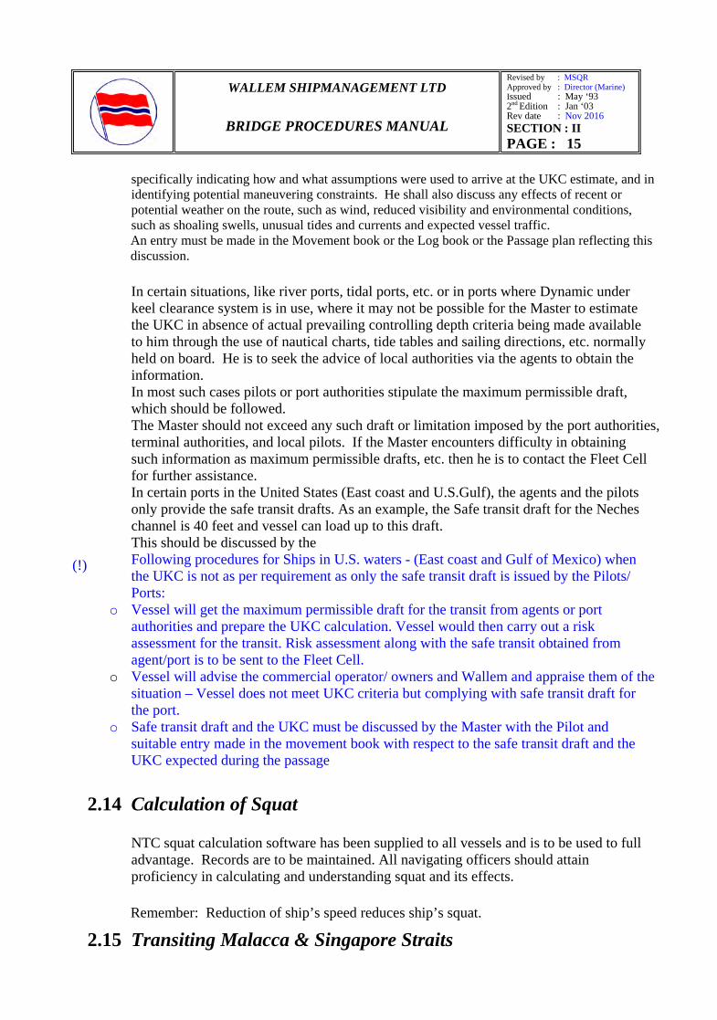
specifically indicating how and what assumptions were used to arrive at the UKC estimate, and in identifying potential maneuvering constraints. He shall also discuss any effects of recent or potential weather on the route, such as wind, reduced visibility and environmental conditions, such as shoaling swells, unusual tides and currents and expected vessel traffic.
An entry must be made in the Movement book or the Log book or the Passage plan reflecting this discussion.
In certain situations, like river ports, tidal ports, etc. or in ports where Dynamic under keel clearance system is in use, where it may not be possible for the Master to estimate the UKC in absence of actual prevailing controlling depth criteria being made available to him through the use of nautical charts, tide tables and sailing directions, etc. normally held on board. He is to seek the advice of local authorities via the agents to obtain the information. In most such cases pilots or port authorities stipulate the maximum permissible draft, which should be followed. The Master should not exceed any such draft or limitation imposed by the port authorities, terminal authorities, and local pilots. If the Master encounters difficulty in obtaining such information as maximum permissible drafts, etc. then he is to contact the Fleet Cell for further assistance.
In certain ports in the United States (East coast and U.S.Gulf), the agents and the pilots only provide the safe transit drafts. As an example, the Safe transit draft for the Neches channel is 40 feet and vessel can load up to this draft. This should be discussed by the
Following procedures for Ships in U.S. waters - (East coast and Gulf of Mexico) when the UKC is not as per requirement as only the safe transit draft is issued by the Pilots/ Ports:
o Vessel will get the maximum permissible draft for the transit from agents or port authorities and prepare the UKC calculation. Vessel would then carry out a risk assessment for the transit. Risk assessment along with the safe transit obtained from agent/port is to be sent to the Fleet Cell.
o Vessel will advise the commercial operator/ owners and Wallem and appraise them of the situation – Vessel does not meet UKC criteria but complying with safe transit draft for the port.
o Safe transit draft and the UKC must be discussed by the Master with the Pilot and suitable entry made in the movement book with respect to the safe transit draft and the UKC expected during the passage
2.14 Calculation of Squat NTC squat calculation software has been supplied to all vessels and is to be used to full advantage. Records are to be maintained. All navigating officers should attain proficiency in calculating and understanding squat and its effects.
Remember: Reduction of ship’s speed reduces ship’s squat.
2.15 Transiting Malacca & Singapore Straits
(!)
WALLEM SHIPMANAGEMENT LTD
BRIDGE PROCEDURES MANUAL
Revised by : MSQR Approved by : Director (Marine) Issued : May ‘93 2nd Edition : Jan ‘03 Rev date : Nov 2016 SECTION : II PAGE : 16
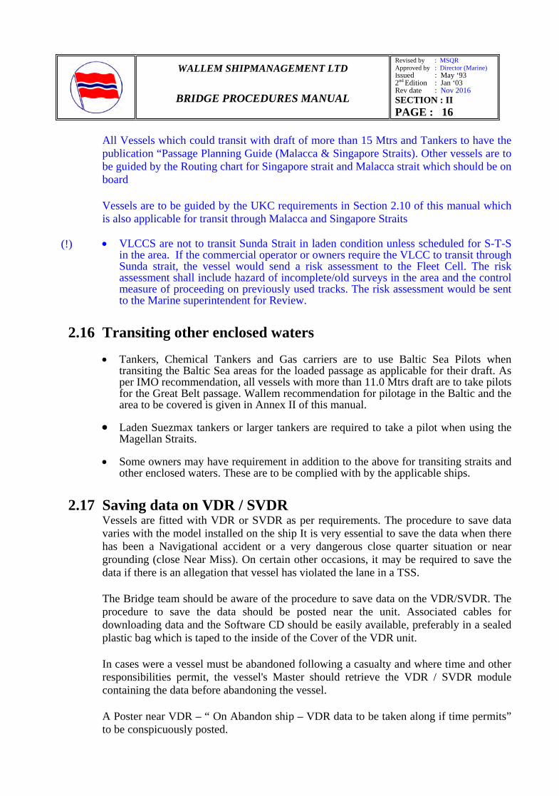
All Vessels which could transit with draft of more than 15 Mtrs and Tankers to have the publication “Passage Planning Guide (Malacca & Singapore Straits). Other vessels are to be guided by the Routing chart for Singapore strait and Malacca strait which should be on board Vessels are to be guided by the UKC requirements in Section 2.10 of this manual which is also applicable for transit through Malacca and Singapore Straits • VLCCS are not to transit Sunda Strait in laden condition unless scheduled for S-T-S
in the area. If the commercial operator or owners require the VLCC to transit through Sunda strait, the vessel would send a risk assessment to the Fleet Cell. The risk assessment shall include hazard of incomplete/old surveys in the area and the control measure of proceeding on previously used tracks. The risk assessment would be sent to the Marine superintendent for Review.
2.16 Transiting other enclosed waters
• Tankers, Chemical Tankers and Gas carriers are to use Baltic Sea Pilots when transiting the Baltic Sea areas for the loaded passage as applicable for their draft. As per IMO recommendation, all vessels with more than 11.0 Mtrs draft are to take pilots for the Great Belt passage. Wallem recommendation for pilotage in the Baltic and the area to be covered is given in Annex II of this manual.
• Laden Suezmax tankers or larger tankers are required to take a pilot when using the
Magellan Straits.
• Some owners may have requirement in addition to the above for transiting straits and other enclosed waters. These are to be complied with by the applicable ships.
2.17 Saving data on VDR / SVDR Vessels are fitted with VDR or SVDR as per requirements. The procedure to save data varies with the model installed on the ship It is very essential to save the data when there has been a Navigational accident or a very dangerous close quarter situation or near grounding (close Near Miss). On certain other occasions, it may be required to save the data if there is an allegation that vessel has violated the lane in a TSS. The Bridge team should be aware of the procedure to save data on the VDR/SVDR. The procedure to save the data should be posted near the unit. Associated cables for downloading data and the Software CD should be easily available, preferably in a sealed plastic bag which is taped to the inside of the Cover of the VDR unit. In cases were a vessel must be abandoned following a casualty and where time and other responsibilities permit, the vessel's Master should retrieve the VDR / SVDR module containing the data before abandoning the vessel. A Poster near VDR – “ On Abandon ship – VDR data to be taken along if time permits” to be conspicuously posted.
(!)
WALLEM SHIPMANAGEMENT LTD
BRIDGE PROCEDURES MANUAL
Revised by : MSQR Approved by : Director (Marine) Issued : May ‘93 2nd Edition : Jan ‘03 Rev date : Nov 2016 SECTION : VI PAGE : 1/2
SECTION VI
BRIDGE CHECK LIST - 1
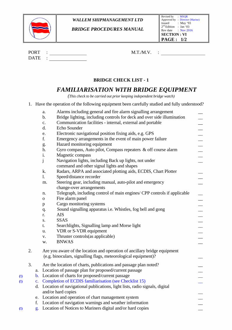
6.1 FAMILIARISATION WITH BRIDGE EQUIPMENT (This check to be carried out prior keeping independent bridge watch)
1. Have the operation of the following equipment been carefully studied and fully understood?
a. Alarms including general and fire alarm signalling arrangement __ b. Bridge lighting, including controls for deck and over side illumination __ c. Communication facilities - internal, external and portable __ d. Echo Sounder __ e. Electronic navigational position fixing aids, e.g. GPS __ f. Emergency arrangements in the event of main power failure __ g. Hazard monitoring equipment __ h. Gyro compass, Auto pilot, Compass repeaters & off course alarm __ i. Magnetic compass __ j Navigation lights, including Back up lights, not under __ command and other signal lights and shapes
k. Radars, ARPA and associated plotting aids, ECDIS, Chart Plotter __ l. Speed/distance recorder __ m. Steering gear, including manual, auto-pilot and emergency __
change-over arrangements n. Telegraph, including control of main engines/ CPP controls if applicable __
o Fire alarm panel __ p Cargo monitoring systems __
q. Sound signalling apparatus i.e. Whistles, fog bell and gong __ r. AIS __ s. SSAS __ t. Searchlights, Signalling lamp and Morse light __ u. VDR or S-VDR equipment __ v. Thruster controls(as applicable) __ w. BNWAS __ 2. Are you aware of the location and operation of ancillary bridge equipment (e.g. binoculars, signalling flags, meteorological equipment)? __
3. Are the location of charts, publications and passage plan noted? __ a. Location of passage plan for proposed/current passage __ b. Location of charts for proposed/current passage __ c. Completion of ECDIS familiarisation (see Checklist 15) __ d. Location of navigational publications, light lists, radio signals, digital
and/or hard copies __ e. Location and operation of chart management system __ f. Location of navigation warnings and weather information __ g. Location of Notices to Mariners digital and/or hard copies __
PORT : M.T./M.V. : DATE :
(!) (!) (!)
WALLEM SHIPMANAGEMENT LTD
BRIDGE PROCEDURES MANUAL
Revised by : MSQR Approved by : Director (Marine) Issued : May ‘93 2nd Edition : Jan ‘03 Rev date : Nov 2016 SECTION : VI PAGE : 1/2
PORT : M.T./M.V. : DATE :
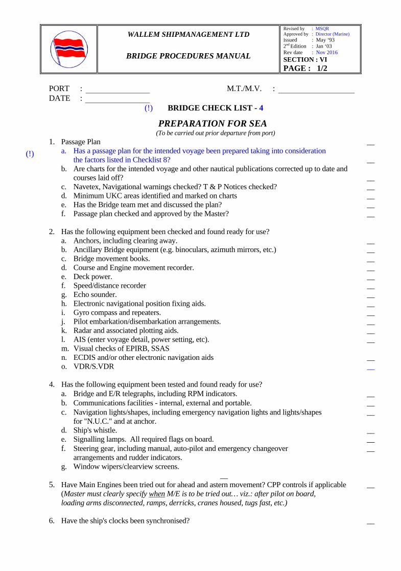
BRIDGE CHECK LIST - 4
6.4 PREPARATION FOR SEA (To be carried out prior departure from port)
1. Passage Plan __ a. Has a passage plan for the intended voyage been prepared taking into consideration
the factors listed in Checklist 8? __ b. Are charts for the intended voyage and other nautical publications corrected up to date and
courses laid off? __ c. Navetex, Navigational warnings checked? T & P Notices checked? __ d. Minimum UKC areas identified and marked on charts __ e. Has the Bridge team met and discussed the plan? __ f. Passage plan checked and approved by the Master? __
2. Has the following equipment been checked and found ready for use? a. Anchors, including clearing away. __ b. Ancillary Bridge equipment (e.g. binoculars, azimuth mirrors, etc.) __ c. Bridge movement books. __ d. Course and Engine movement recorder. __ e. Deck power. __ f. Speed/distance recorder __ g. Echo sounder. __ h. Electronic navigational position fixing aids. __
i. Gyro compass and repeaters. __ j. Pilot embarkation/disembarkation arrangements. __ k. Radar and associated plotting aids. __
l. AIS (enter voyage detail, power setting, etc). __ m. Visual checks of EPIRB, SSAS n. ECDIS and/or other electronic navigation aids __ o. VDR/S.VDR __
4. Has the following equipment been tested and found ready for use?
a. Bridge and E/R telegraphs, including RPM indicators. __ b. Communications facilities - internal, external and portable. __ c. Navigation lights/shapes, including emergency navigation lights and lights/shapes __ for "N.U.C." and at anchor.
d. Ship's whistle. __ e. Signalling lamps. All required flags on board. __
f. Steering gear, including manual, auto-pilot and emergency changeover __ arrangements and rudder indicators.
g. Window wipers/clearview screens. __ 5. Have Main Engines been tried out for ahead and astern movement? CPP controls if applicable __ (Master must clearly specify when M/E is to be tried out… viz.: after pilot on board, loading arms disconnected, ramps, derricks, cranes housed, tugs fast, etc.) 6. Have the ship's clocks been synchronised? __
(!)
(!)
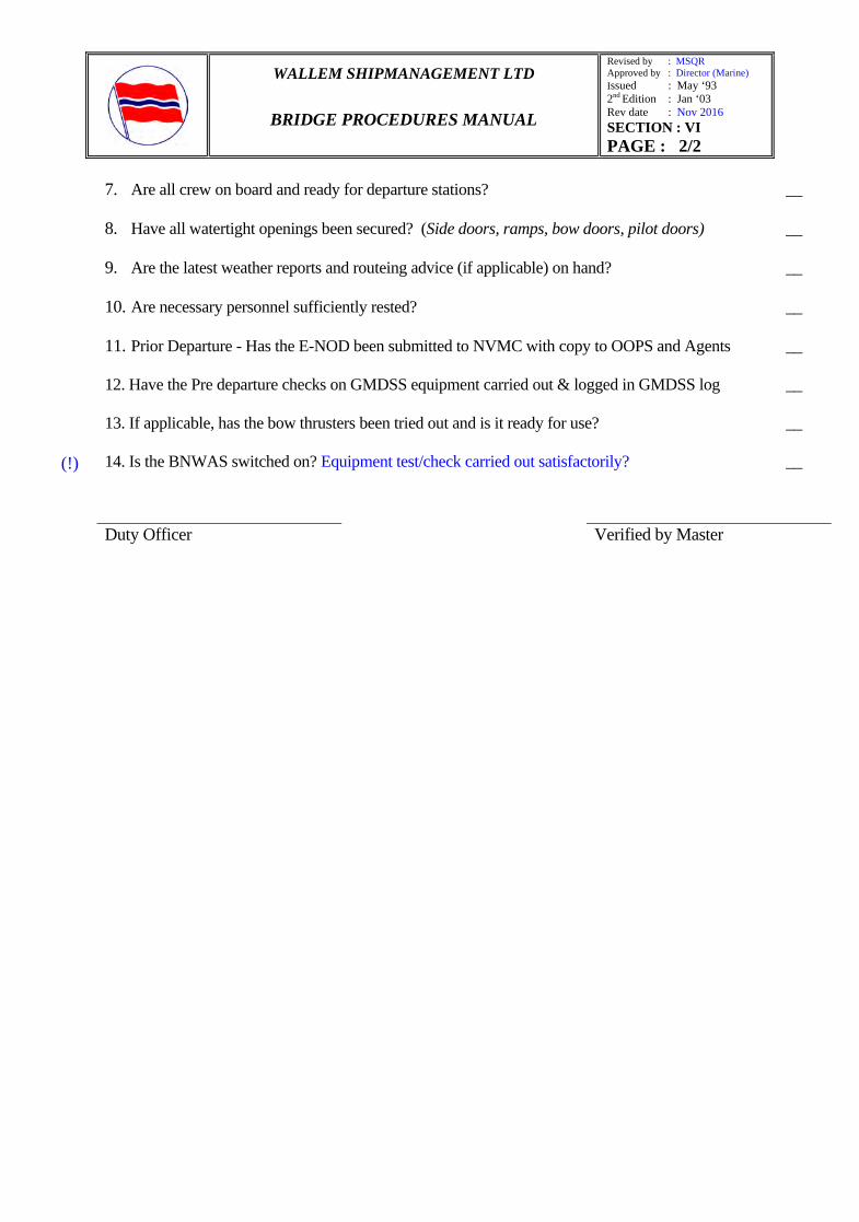
WALLEM SHIPMANAGEMENT LTD
BRIDGE PROCEDURES MANUAL
Revised by : MSQR Approved by : Director (Marine) Issued : May ‘93 2nd Edition : Jan ‘03 Rev date : Nov 2016 SECTION : VI PAGE : 2/2
7. Are all crew on board and ready for departure stations? __
8. Have all watertight openings been secured? (Side doors, ramps, bow doors, pilot doors) __
9. Are the latest weather reports and routeing advice (if applicable) on hand? __
10. Are necessary personnel sufficiently rested? __
11. Prior Departure - Has the E-NOD been submitted to NVMC with copy to OOPS and Agents __
12. Have the Pre departure checks on GMDSS equipment carried out & logged in GMDSS log __
13. If applicable, has the bow thrusters been tried out and is it ready for use? __ 14. Is the BNWAS switched on? Equipment test/check carried out satisfactorily? __ Duty Officer Verified by Master
(!)
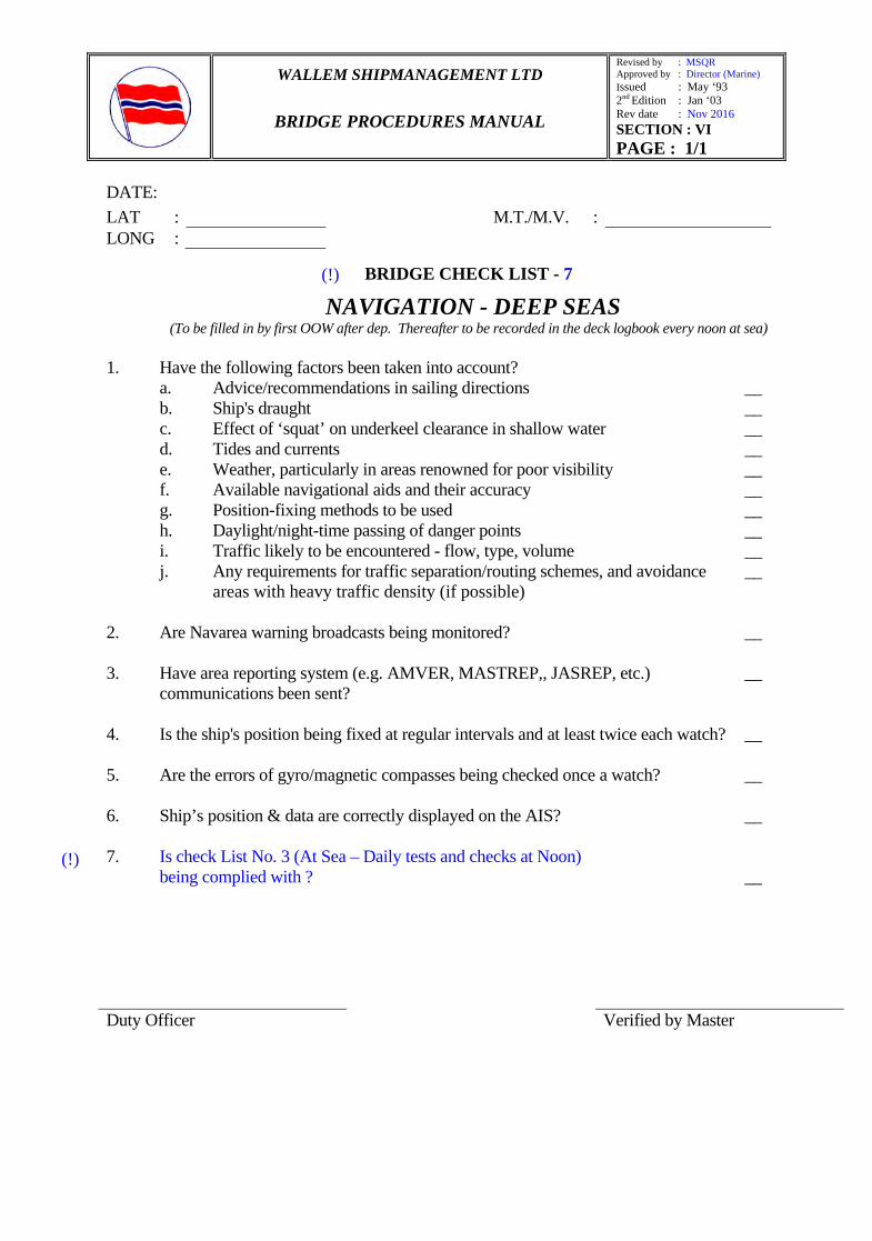
WALLEM SHIPMANAGEMENT LTD
BRIDGE PROCEDURES MANUAL
Revised by : MSQR Approved by : Director (Marine) Issued : May ‘93 2nd Edition : Jan ‘03 Rev date : Nov 2016 SECTION : VI PAGE : 1/1
DATE:
BRIDGE CHECK LIST - 7
6.7 NAVIGATION - DEEP SEAS (To be filled in by first OOW after dep. Thereafter to be recorded in the deck logbook every noon at sea)
1. Have the following factors been taken into account?
a. Advice/recommendations in sailing directions __ b. Ship's draught __
c. Effect of ‘squat’ on underkeel clearance in shallow water __ d. Tides and currents __ e. Weather, particularly in areas renowned for poor visibility __ f. Available navigational aids and their accuracy __ g. Position-fixing methods to be used __ h. Daylight/night-time passing of danger points __ i. Traffic likely to be encountered - flow, type, volume __ j. Any requirements for traffic separation/routing schemes, and avoidance __
areas with heavy traffic density (if possible) 2. Are Navarea warning broadcasts being monitored? __ 3. Have area reporting system (e.g. AMVER, MASTREP,, JASREP, etc.) __ communications been sent? 4. Is the ship's position being fixed at regular intervals and at least twice each watch? __ 5. Are the errors of gyro/magnetic compasses being checked once a watch? __
6. Ship’s position & data are correctly displayed on the AIS? __
7. Is check List No. 3 (At Sea – Daily tests and checks at Noon) being complied with ? __ Duty Officer Verified by Master
LAT : M.T./M.V. : LONG :
(!)
(!)
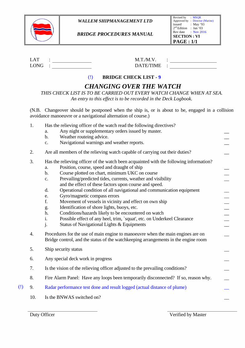
WALLEM SHIPMANAGEMENT LTD
BRIDGE PROCEDURES MANUAL
Revised by : MSQR Approved by : Director (Marine) Issued : May ‘93 2nd Edition : Jan ‘03 Rev date : Nov 2016 SECTION : VI PAGE : 1/1
LAT : M.T./M.V. : LONG : DATE/TIME :
BRIDGE CHECK LIST - 9
6.9 CHANGING OVER THE WATCH THIS CHECK LIST IS TO BE CARRIED OUT EVERY WATCH CHANGE WHEN AT SEA.
An entry to this effect is to be recorded in the Deck Logbook.
(N.B. Changeover should be postponed when the ship is, or is about to be, engaged in a collision avoidance manoeuvre or a navigational alternation of course.) 1. Has the relieving officer of the watch read the following directives?
a. Any night or supplementary orders issued by master. __ b. Weather routeing advice. __
c. Navigational warnings and weather reports. __ 2. Are all members of the relieving watch capable of carrying out their duties? __ 3. Has the relieving officer of the watch been acquainted with the following information? a. Position, course, speed and draught of ship __ b. Course plotted on chart, minimum UKC on course __ c. Prevailing/predicted tides, currents, weather and visibility __ and the effect of these factors upon course and speed. d. Operational condition of all navigational and communication equipment __ e. Gyro/magnetic compass errors __ f. Movement of vessels in vicinity and effect on own ship __ g. Identification of shore lights, buoys, etc. __ h. Conditions/hazards likely to be encountered on watch __ i. Possible effect of any heel, trim, `squat', etc. on Underkeel Clearance __ j. Status of Navigational Lights & Equipments __ 4. Procedures for the use of main engine to manoeuvre when the main engines are on __ Bridge control, and the status of the watchkeeping arrangements in the engine room 5. Ship security status __ 6. Any special deck work in progress __ 7. Is the vision of the relieving officer adjusted to the prevailing conditions? __ 8. Fire Alarm Panel: Have any loops been temporarily disconnected? If so, reason why. __
9. Radar performance test done and result logged (actual distance of plume) __ 10. Is the BNWAS switched on? __
Duty Officer Verified by Master
(!)
(!)

WALLEM SHIPMANAGEMENT LTD
BRIDGE PROCEDURES MANUAL
Revised by : MSQR Approved by : Director (Marine) Issued : May ‘93 2nd Edition : Jan ‘03 Rev date : Nov 2016 SECTION :VI PAGE : 1/1
Port : M.T./M.V. : DATE/TIME :
BRIDGE CHECK LIST – 17 6.17 PASSAGE PLANNING WITH ECDIS EQUIPMENT
(EXECUTION & MONITORING) 1. Get the Bridge environment ECDIS ready. ____ 2. Carry out a voyage specific risk assessment and implement risk mitigation
measures. ____ 3. Verify that main and emergency power supply is available to ECDIS. ____ 4. Test input from all sensors connected to ECDIS. ____ 5. Verify that the ECDIS is set to the correct customised display mode. ____ 6. Set the appropriate position plotting frequency and other fields required in the electronic log book. ____ 7. Prepare contingency plans for failure of critical equipment, including sensors. ____ 8. Check the accuracy of inputs from various sensors. ____ 9. Verify that the correct route has been called up for monitoring. ____ 10. Do not disable or ignore any alarms and indications which require your attention. ____ 11. Adjust the display for night vision to avoid impairing look out duties. ____ 12. When using the preferred ‘True Motion’ mode of display, ensure that ship’s position is automatically reset at the preset distance from the edge of the display. ____
13. When using radar overlay, avoid cluttering the display with unnecessary info. ____ 14. If Radar or AIS targets can be displayed on the ECDIS, determine what
target vector modes are available and how to switch between and differentiate them ____
15. Echo Referencing may be considered as an alternate position fixing method. ____ 16. Do not enable the function of ‘Automatic shift to DR mode’, in case of Failure of primary position fixing system without thoroughly understanding the implications of same. ____
17. Validate the vessel’s position by traditional position fixing methods such as by visual bearings, radar bearings and ranges, parallel indexing techniques, transit and clearing bearings. ____
18. Update the electronic log book for additional remarks, in case of occurrence of any event which can affect safety of navigation. ____ 19. Cross check the accuracy of displayed navigational information in the SENC
by visual, radar as well as by all other available means. ____ 20. Verify and adjust the settings for the Shallow, Safety and Deep contours,
Safety Depth, vector time for Alarms and Indications, CPA distance and TCPA time for targets, own ship position display as symbol or contour, way point approach, ahead or behind schedule, deviation from route etc; to suit the prevailing weather conditions, traffic density and proximity of added navigational hazards. ____
21. Be prepared to respond to discrepancies between automatic and manual fixes to ensure safety of navigation. ____
22. Understand that full and proper monitoring of the route is required to be carried out on ‘Back Up Arrangements’ too, for safe taking over of ECDIS
functions to ensure that ECDIS failure does not develop in critical situation. ____ ___________________________________ ______________________________________
Navigating Officer Verified by Master
(!)

WALLEM SHIPMANAGEMENT LTD
BRIDGE PROCEDURES MANUAL
Revised by : MSQR Approved by : Director (Marine) Issued : May ‘93 2nd Edition : Jan ‘03 Rev : Nov 2016 SECTION :VI PAGE : 1/1
Port : M.T./M.V. : Voy No. : DATE/TIME :
BRIDGE CHECK LIST – 19
6.19 UKC Calculations
Summary Of Calculations Forward Aft Amidships
Squa
t Cal
cula
tion
SW Draft (In Meters) FWA / DWA / SW (Density) : Fresh Water Draft (In Meters) in DW Maximum Transit Speed ( Knots) Block Co-Efficient (Cᵦ) List Correction (In Meters): 0 (+) Deepest Draft (In Meters) ⁰ Squat Correction (In Meters): Open / Confined (+)
EFFECTIVE DRAFT (In Meters) (A):
Fact
or A
ffec
ting
Cha
rted
Dep
th
Minimum Controlling Depth (In Meters) CD: Height of Tide (In Meters): @ Local Time Wind / Atmospheric Pressure Nature of Bottom (Eg. Sand Waves & Siltation) Obstructions beneath water (Eg. Pipelines) Reliability of Data (Refer CATZOC on ECDIS) Weather Allowance (Heave, Roll & Pitch)
Fact
ots
affe
ctin
gVes
ssel
dr
aft
Allowance for Water Density Heel (Due to External Forces) Wave Response Hog / Sag Heel Due to Turning
CORRECTED CONTROLLING DEPTH (B) : Anticipated Under Keel Clearance (In Meters) (B)-(A) :
EC
DIS
SA
FET
Y SHALLOW CONTOUR (Maximum Static Draft) In Meters
SAFETY DEPTH (10% OF DD + SD) In Meters SAFETY CONTOUR (10% OF DD + SD) In Meters SAFETY DEPTH (20% OF DD + SD) In Meters SAFETY CONTOUR (20% OF DD + SD) In Meters DEEP CONTOUR (2 X VESSEL STATIC DRAFT) In Meters
(!!)
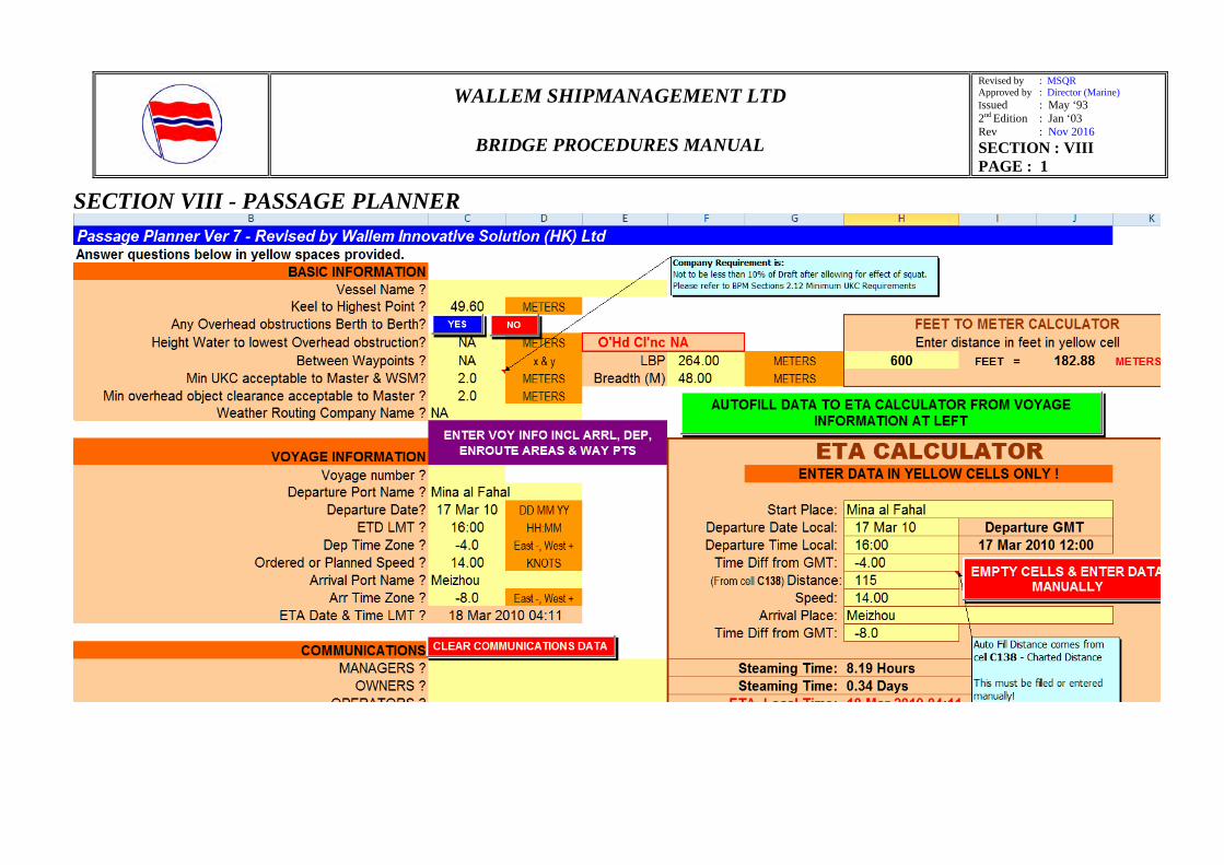
WALLEM SHIPMANAGEMENT LTD
BRIDGE PROCEDURES MANUAL
Revised by : MSQR Approved by : Director (Marine) Issued : May ‘93 2nd Edition : Jan ‘03 Rev : Nov 2016 SECTION : VIII PAGE : 1
SECTION VIII - PASSAGE PLANNER