table of contents - steadypower.com of contents section-page ... operator’s manual asco ... (asco...
TRANSCRIPT
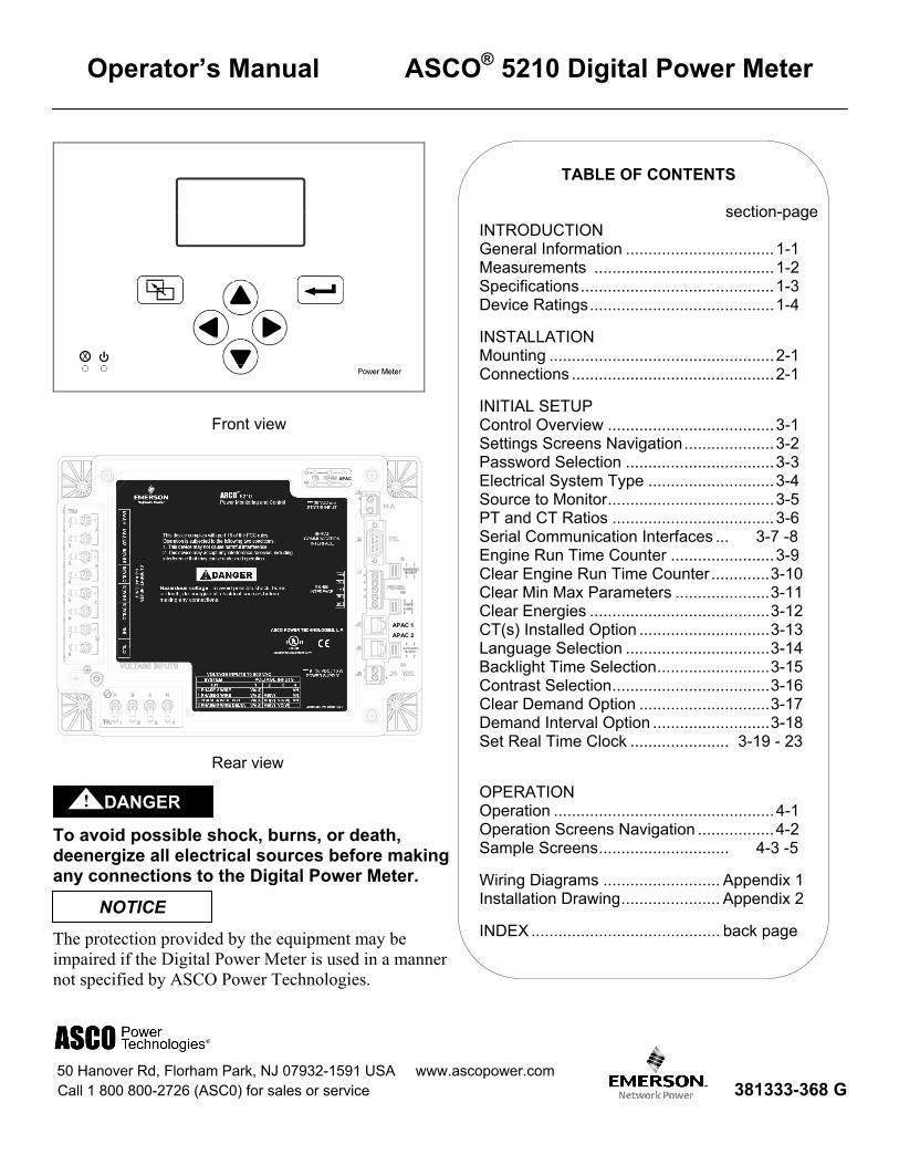
TABLE OF CONTENTS
section-page
INTRODUCTION General Information ................................. 1-1 Measurements ........................................ 1-2 Specifications ........................................... 1-3 Device Ratings ......................................... 1-4
INSTALLATION Mounting .................................................. 2-1 Connections ............................................. 2-1
INITIAL SETUP Control Overview ..................................... 3-1 Settings Screens Navigation .................... 3-2 Password Selection ................................. 3-3 Electrical System Type ............................ 3-4 Source to Monitor ..................................... 3-5 PT and CT Ratios .................................... 3-6 Serial Communication Interfaces ... 3-7 -8 Engine Run Time Counter ....................... 3-9 Clear Engine Run Time Counter ............. 3-10 Clear Min Max Parameters ..................... 3-11 Clear Energies ........................................ 3-12 CT(s) Installed Option ............................. 3-13 Language Selection ................................ 3-14 Backlight Time Selection ......................... 3-15 Contrast Selection ................................... 3-16 Clear Demand Option ............................. 3-17 Demand Interval Option .......................... 3-18 Set Real Time Clock ...................... 3-19 - 23
OPERATION Operation ................................................. 4-1 Operation Screens Navigation ................. 4-2 Sample Screens ............................. 4-3 -5
Wiring Diagrams .......................... Appendix 1 Installation Drawing ...................... Appendix 2
INDEX .......................................... back page
Operator’s Manual ASCO® 5210 Digital Power Meter
Front view
Rear view
To avoid possible shock, burns, or death, deenergize all electrical sources before making any connections to the Digital Power Meter.
The protection provided by the equipment may be impaired if the Digital Power Meter is used in a manner not specified by ASCO Power Technologies.
50 Hanover Rd, Florham Park, NJ 07932-1591 USA www.ascopower.com Call 1 800 800-2726 (ASC0) for sales or service 381333-368 G
NOTICE
DANGER !
APAC 1
APAC 2
APAC

1-1 Introduction Operator’s Manual 381333-368G 5210 Digital Power Meter
General Information The Catalog 5210 Digital Power Meter (DPM) collects real-time power system information from ASCO Power Control Systems and Automatic Transfer Switches (ASCO Series 300, 4000 Series, 7000 Series). The DPM provides measurement for voltage, current, active power, reactive power, apparent power, active energy, reactive energy, apparent energy, power factor, and frequency. The intended use of the DPM is in the standard metering applications.
The DPM has built in serial communication interfaces. ASCOBUS II and serial Modbus RTU protocols are available to communicate with ASCO Power Quest or other monitoring applications via the built-in RS485 port or through the use of ASCO Catalog 5150 Connectivity Module (Accessory 72E). The APAC interface is used for communication with ASCO Catalog 5140 Quad-Ethernet Module (Accessory 72EE).
The DPM includes a backlit graphic LCD display and membrane controls (keys). All monitoring and control functions can be done from the front of the unit for convenience and safety.
The DPM can accommodate the following three phase and single phase system types: • Single phase – 2 wire system (1 – 2W) • Single phase – 3 wire system (1 – 3W) • Three phase – 3 wire Delta system (3 – 3W) • Three phase – 4 wire WYE system (3 – 4W)
Monitored & Calculated Data The following computed parameters are available both on the local display and through the serial interface:
• Line–to–neutral voltages (VAN, VBN, VCN) • Line–to–neutral voltage average (VAVE) • Line–to–line voltages (VAB, VBC, VCA) • Line–to–line voltage average (VLAVE) • Current on each phase (IA, IB, IC) • Current in the neutral conductor (IN) • Average current (IAVE) • Active power, kW per phase and total (WA, WB, WC, WT) • Reactive power, kVAR per phase and total (VARA, VARB, VARC, VART) • Apparent power, kVA per phase and total (VAA, VAB, VAC, VAT) • kWhours importing, exporting and net (kWhIMP, kWhEXP, kWhNET) • kVARhours leading, lagging and net (kVARhLEAD, kVARhLAG, kVARhNET) • kVAhours net (kVAhNET) • Power factor (PF) • Signal frequency (Hz) • Total harmonic distortion (THD) • Maximum kW demand (hourly, daily, monthly, yearly, etc.) with real-time clock
Transfer Switch Position Input (optional) Used when the Digital Power Meter is providing measurement on the load terminal of a transfer switch.
Cleaning The exterior of the Digital Power Meter should be cleaned by wiping the front panel of the display unit with a soft cloth and cleaning agents that are not alcohol based, and are non-flammable, non-explosive. All other servicing should be performed by authorized factory personnel.
5210 Digital Power Meter Operator’s Manual 381333-368G Introduction 1-2
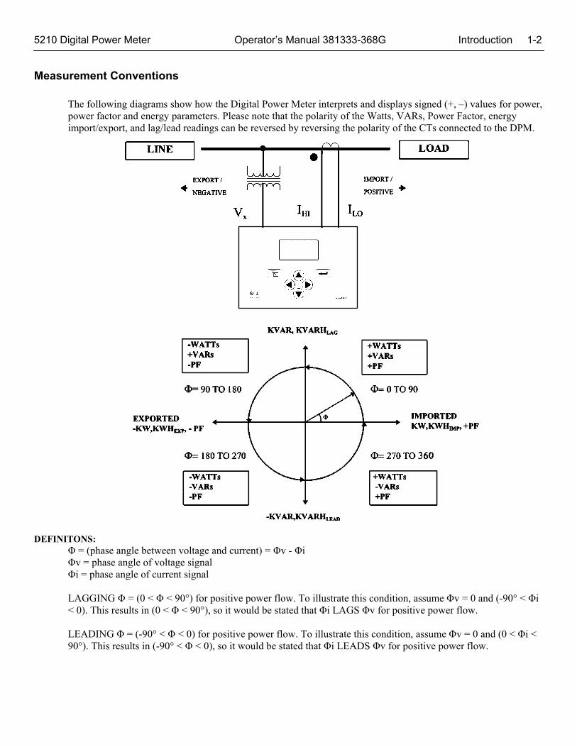
Measurement Conventions
The following diagrams show how the Digital Power Meter interprets and displays signed (+, –) values for power, power factor and energy parameters. Please note that the polarity of the Watts, VARs, Power Factor, energy import/export, and lag/lead readings can be reversed by reversing the polarity of the CTs connected to the DPM.
DEFINITONS: Φ = (phase angle between voltage and current) = Φv - Φi Φv = phase angle of voltage signal Φi = phase angle of current signal LAGGING Φ = (0 < Φ < 90°) for positive power flow. To illustrate this condition, assume Φv = 0 and (-90° < Φi < 0). This results in (0 < Φ < 90°), so it would be stated that Φi LAGS Φv for positive power flow. LEADING Φ = (-90° < Φ < 0) for positive power flow. To illustrate this condition, assume Φv = 0 and (0 < Φi < 90°). This results in (-90° < Φ < 0), so it would be stated that Φi LEADS Φv for positive power flow.
1-3 Introduction Operator’s Manual 381333-368G 5210 Digital Power Meter
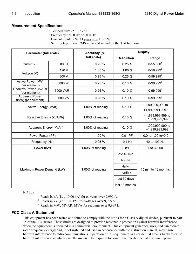
Measurement Specifications • Temperature: 25 ˚C / 77˚F • Frequency : 50.0 Hz or 60.0 Hz • Current input : 2 % < I FULL SCALE < 125 % • Sensing type: True RMS up to and including the 31st harmonic.
Parameter (full scale)
Accuracy (% full scale)
Display
Resolution Range
Current (I) 5.000 A 0.25 % 0.25 % 0-55 0001
Voltage (V) 120 V 1.00 % 1.00 % 0-59 9992
600 V 0.25 % 0.25 % 0-59 9992
Active Power (kW) (per element)
3000 W 0.25 % 0.10 % 0-99 9993
Reactive Power (kVAR) (per element)
3000 VAR 0.25 % 0.10 % 0-99 9993
Apparent Power (kVA) (per element)
3000 VA 0.25 % 0.10 % 0-99 9993
Active Energy (kWh) 1.00% of reading 0.10 % - 1,999,999,999 to
+1,999,999,999
Reactive Energy (kVARh) 1.00% of reading 0.10 % - 1,999,999,999 to
+1,999,999,999
Apparent Energy (kVAh) 1.00% of reading 0.10 % - 1,999,999,999 to
+1,999,999,999
Power Factor (PF) 1.00 % 0.01 PF -0.0 to 1.00 to+0,0
Frequency (Hz) 0.25 % 0.1 Hz 40 to 100 Hz
Power (kW) 1.00% of reading 1 kW 1 to 32000
Maximum Power Demand (kW) 1.00% of reading
last 15 min
15 min to 13 months
hourly
daily
monthly
last 30 days
last 13 months
NOTES: 1 Reads in kA (i.e., 10.00 kA) for currents over 9,999 A. 2 Reads in kV (i.e., 10.0 kV) for voltages over 9,999 V. 3 Reads in MW, MVAR, MVA for readings over 9,999 k.
FCC Class A Statement This equipment has been tested and found to comply with the limits for a Class A digital device, pursuant to part 15 of the FCC Rules. These limits are designed to provide reasonable protection against harmful interference when the equipment is operated in a commercial environment. This equipment generates, uses, and can radiate radio frequency energy and, if not installed and used in accordance with the instruction manual, may cause harmful interference to radio communications. Operation of this equipment in a residential area is likely to cause harmful interference in which case the user will be required to correct the interference at his own expense.
5210 Digital Power Meter Operator’s Manual 381333-368G Introduction 1-4
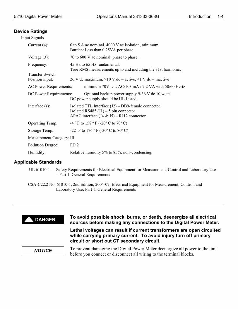
Device Ratings Input Signals
Current (4): 0 to 5 A ac nominal. 4000 V ac isolation, minimum Burden: Less than 0.25VA per phase.
Voltage (3): 70 to 600 V ac nominal, phase to phase.
Frequency: 45 Hz to 65 Hz fundamental. True RMS measurements up to and including the 31st harmonic.
Transfer Switch Position input: 26 V dc maximum, >10 V dc = active, <1 V dc = inactive
AC Power Requirements: minimum 70V L-L AC/103 mA / 7.2 VA with 50/60 Hertz
DC Power Requirements: Optional backup power supply 9-36 V dc 10 watts DC power supply should be UL Listed.
Interface (s): Isolated TTL Interface (J2) – DB9-female connector Isolated RS485 (J1) – 5 pin connector APAC interface (J4 & J5) – RJ12 connector
Operating Temp.: -4 º F to 158 º F (-20º C to 70º C)
Storage Temp.: -22 ºF to 176 º F (-30º C to 80º C)
Measurement Category: III
Pollution Degree: PD 2
Humidity: Relative humidity 5% to 85%, non–condensing.
Applicable Standards
UL 61010-1 Safety Requirements for Electrical Equipment for Measurement, Control and Laboratory Use – Part 1: General Requirements CSA-C22.2 No. 61010-1, 2nd Edition, 2004-07, Electrical Equipment for Measurement, Control, and Laboratory Use; Part 1: General Requirements
To avoid possible shock, burns, or death, deenergize all electrical sources before making any connections to the Digital Power Meter.
Lethal voltages can result if current transformers are open circuited while carrying primary current. To avoid injury turn off primary circuit or short out CT secondary circuit.
To prevent damaging the Digital Power Meter deenergize all power to the unit before you connect or disconnect all wiring to the terminal blocks.
NOTICE
DANGER !
2-1 Installation Operator’s Manual 381333-368G 5210 Digital Power Meter
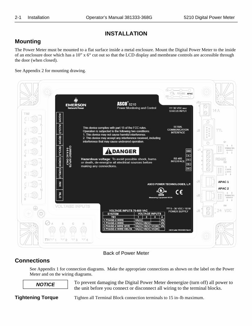
INSTALLATION Mounting The Power Meter must be mounted to a flat surface inside a metal enclosure. Mount the Digital Power Meter to the inside of an enclosure door which has a 10” x 6“ cut out so that the LCD display and membrane controls are accessible through the door (when closed). See Appendix 2 for mounting drawing.
Back of Power Meter
Connections See Appendix 1 for connection diagrams. Make the appropriate connections as shown on the label on the Power Meter and on the wiring diagrams.
To prevent damaging the Digital Power Meter deenergize (turn off) all power to the unit before you connect or disconnect all wiring to the terminal blocks.
Tightening Torque Tighten all Terminal Block connection terminals to 15 in–lb maximum.
NOTICE
APAC 1
APAC 2
APAC
5210 Digital Power Meter Operator’s Manual 381333-368G Installation 2-2
Power Supply Connections (TB1 andJ6) See NOTICE above. AC Power Supply (TB1) - Connect the Phases A, B, C, and Neutral (if present) to terminal block TB1 as marked on the Power Meter. Refer to the labelling below the terminal block. Minimum AC input is 70V L-L AC and maximum AC input is 600V L-L AC with 50/60 Hertz frequency.
DC Power Supply (J6) – This is an optional but recommended backup dc power connection. If there is an AC power interruption, a DC power supply will allow communication with the Power Meter. Use a Class 1 power supply that is UL Listed. Connect the 0.3 amp. 24 volt dc power supply to terminal J6.1 (+) and terminal J6.2 (com) on Connector J6 marked on the Power Meter. Refer to the labelling below terminal block. The terminals accept 12-20 AWG stranded copper wire.
To avoid possible shock, burns, or death, deenergize all electrical sources before making any connections to the Digital Power Meter.
Lethal voltages can result if current transformers are open circuited while carrying primary current. To avoid injury turn off primary circuit or short out CT secondary circuit.
CT Connections (TB2) See DANGER above! Connect the current transformers (CTs) with 5 amp rated secondary to the appropriate terminals marked Current Inputs on the Power Meter. Refer to the labelling above terminal block TB2. Note the shorting block requirements on the Wiring Diagram. The high side (X1 or dot) terminals are marked 0.
Voltage Connections (TB1) See DANGER above! As described in the AC Power Supply section above, connect the system voltage (120 to 600 volts ac with 50/60 Hertz) to the appropriate terminals marked Voltage Inputs on the Power Meter. For system voltages above 600 volts ac use appropriate potential transformers (PTs).Refer to the labelling above terminal block TB3. Note the fusing requirements on the Wiring Diagram. (These input connections are same as the AC Power Supply Connections).
Transfer Switch Position (J3) This connection is used if the Digital Power Meter is connected to a transfer switch’s load terminals that is closed when the transfer switch is connected to the Normal source. If used, connect an unused transfer switch auxiliary contact (Feature 14A) to the appropriate terminals marked N/E Input on the DPM J3 terminals 1 & 2. Refer to the ATS Operator’s Manual and ATS wiring diagram for the location of Feature 14A contact. This connection to the DPM allows it to monitor and display the position of the transfer switch. It also allows the DPM to properly attribute Watts, VA, VARs, PF, and min./max. values to either the Normal or Emergency source. The Source to Monitor setting (page 3-4) must be set to Load.
Ground Connection The Power Meter is provided with a ground screw and ground wire with ring terminal (back lower left). Connect this ground wire to the inside grounded mounting stud.
When the Power Meter is mounted on an enclosure door, install a conductive strap between the enclosure and the door. This connection provides proper grounding which does not rely upon the door hinges.
DANGER !
2-3 Installation Operator’s Manual 381333-368G 5210 Digital Power Meter Communication Network Connections
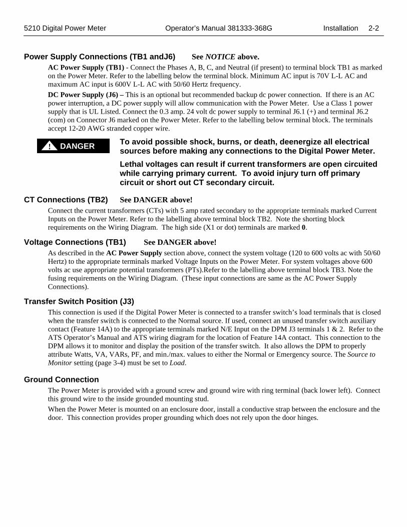
RS–485 Port (J1) - RS–485 Port is used to interface with Monitoring Systems or for networking with other Meters. J1 is used to connect the Power Meter directly to an RS–485 based communications network. Baud rates of 9600 & 19.2k baud are supported on this interface.
Accessory 72E (J2) - Port Supports ASCObus II and serial Modbus protocols. A DB 9 female connector provides 24VDC power (max 100mA) to 5150 Connectivity Module (Acc. 72E).
The Connectivity Module (Acc. 72E) provides Ethernet access that allows user to view data from ASCO automatic transfer switches, Power Managers, and Digital Power Meters.
First, use ASCO cable 489672 (8 inch) or 489672–001 (4 foot) to connect the unit’s serial communications interface connector J2 to the Acc. 72E Connectivity Module connector J2. Then, use only the recommended communication cable (see below) to connect the Acc. 72E Module to the RS-485 network. Connect the transmit and receive communication cable (twisted pairs) as shown on wiring diagrams in Appendix 1.
Acceptable Communication Cable
Type of Cable Acceptable Manufacturer’s Numbers Standard 800 C Belden 9842, 9829, Alpha 6202C, 6222C Plenum Rated Belden 89729, 82729, Alpha 58902
Accessory 72EE (J4, J5) - Ports support the APAC interface for the Group G controller used on new Series 300 3ATS, 3ADTS, 3NTS, 3NDTS transfer switches.
Protocol: APAC
APAC 1
APAC 2
APAC
5210 Digital Power Meter Operator’s Manual 381333-368G Initial Setup 3-1
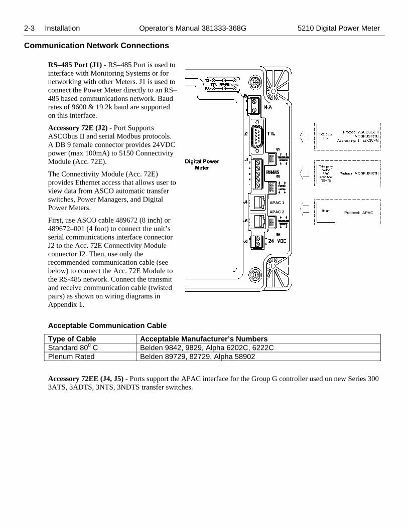
Control Overview Six control buttons perform all monitoring and setting functions. Two levels of screens are used. The top level is the monitoring level and provides information about the power system. The lower level is the settings level. It may be necessary to enter a password to change a setting (see next page).
Left–Right arrow key The left and right arrow keys navigate through both levels of screens.
Enter key The enter key drops from the top level to the lower level settings screens. It also saves a new setting.
Up–Down arrow keys The up and down arrow keys modify a setting (setup parameter) while in the lower level screens.
Escape key The escape key ignores a change and returns to the top level.
Initial Setup After installing the Digital Power Meter you must set these parameters:
Password (required to change any setting) Type of electric system (3Ø-4W, 3Ø-3W, 1Ø-2W, 1Ø-3W) Source to be monitored (normal, emergency, load, other) Potential transformer (PT) and current transformer (CT) ratios Communication Port Settings Engine runtime(Enable or Disable) ATS Position (ON or OFF) Clear Run-time Engine Counter Clear Min max parameters Clear Energies CT Installed option (A, B, C or A-B-C)
If the Digital Power Meter is preinstalled as an ATS accessory, initial setup has already been done. You should set your password and clear the energy settings, however. Then go to Operation on page 4–1.
480V 1000 A 480 kW +1.00 PF 0 kVAR 60.0 Hz 480 kVA 100.0 Hrs
3-2 Initial Setup Operator’s Manual 381333-368G 5210 Digital Power Meter
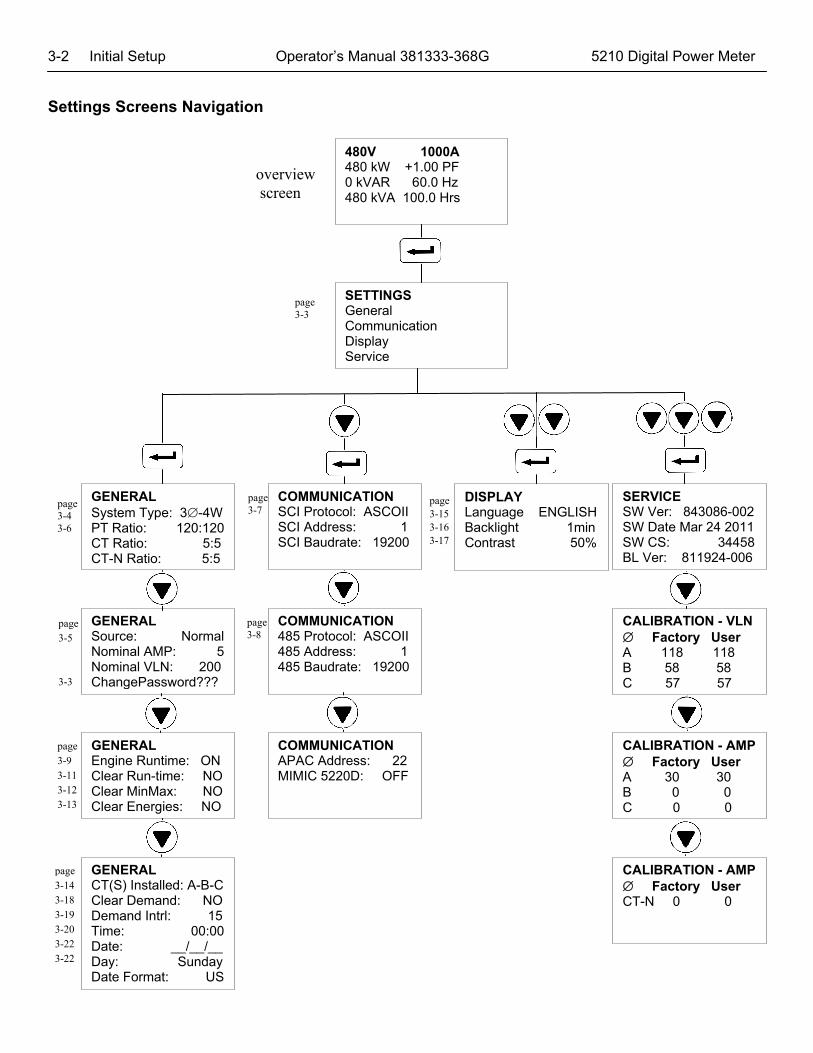
Settings Screens Navigation
480V 1000A 480 kW +1.00 PF 0 kVAR 60.0 Hz 480 kVA 100.0 Hrs
SETTINGS General Communication Display Service
GENERAL System Type: 3-4W PT Ratio: 120:120 CT Ratio: 5:5 CT-N Ratio: 5:5
SERVICE SW Ver: 843086-002 SW Date Mar 24 2011 SW CS: 34458 BL Ver: 811924-006
COMMUNICATION SCI Protocol: ASCOII SCI Address: 1 SCI Baudrate: 19200
DISPLAY Language ENGLISH Backlight 1min Contrast 50%
GENERAL Source: Normal Nominal AMP: 5 Nominal VLN: 200 ChangePassword???
CALIBRATION - VLN Factory User A 118 118 B 58 58 C 57 57
COMMUNICATION 485 Protocol: ASCOII 485 Address: 1 485 Baudrate: 19200
GENERAL Engine Runtime: ON Clear Run-time: NO Clear MinMax: NO Clear Energies: NO
CALIBRATION - AMP Factory User A 30 30 B 0 0 C 0 0
COMMUNICATION APAC Address: 22 MIMIC 5220D: OFF
GENERAL CT(S) Installed: A-B-C Clear Demand: NO Demand Intrl: 15 Time: 00:00 Date: __/__/__ Day: Sunday Date Format: US
CALIBRATION - AMP Factory User CT-N 0 0
page 3-4 3-6
page 3-7
page 3-15 3-16 3-17
page 3-5 3-3
page 3-8
page 3-9 3-11 3-12 3-13
overview screen
page 3-3
page 3-14 3-18 3-19 3-20 3-22 3-22
5210 Digital Power Meter Operator’s Manual 381333-368G Initial Setup 3-3
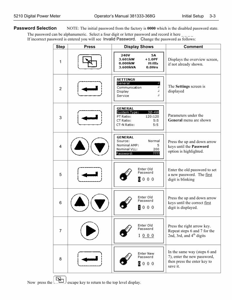
Password Selection NOTE: The initial password from the factory is 0000 which is the disabled password state. The password can be alphanumeric. Select a four digit or letter password and record it here _ _ _ _ If incorrect password is entered you will see Invalid Password. Change the password as follows:
Step Press Display Shows Comment
1
Displays the overview screen, if not already shown.
2
The Settings screen is displayed
3
Parameters under the General menu are shown
4
Press the up and down arrow keys until the Password option is highlighted.
5
Enter the old password to set a new password. The first digit is blinking
6
Press the up and down arrow keys until the correct first digit is displayed.
7
Press the right arrow key. Repeat steps 6 and 7 for the 2nd, 3rd, and 4th digits
8
In the same way (steps 6 and 7), enter the new password, then press the enter key to save it.
Now press the escape key to return to the top level display.
3-4 Initial Setup Operator’s Manual 381333-368G 5210 Digital Power Meter
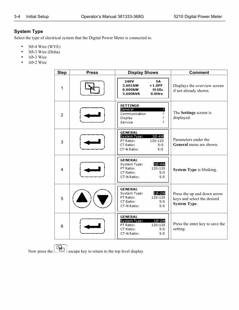
System Type Select the type of electrical system that the Digital Power Meter is connected to.
3Ø-4 Wire (WYE) 3Ø-3 Wire (Delta) 1Ø-3 Wire 1Ø-2 Wire
Step Press Display Shows Comment
1
Displays the overview screen if not already shown.
2
The Settings screen is displayed.
3
Parameters under the General menu are shown.
4
System Type is blinking.
5
Press the up and down arrow keys and select the desired System Type.
6
Press the enter key to save the setting.
Now press the escape key to return to the top level display.
5210 Digital Power Meter Operator’s Manual 381333-368G Initial Setup 3-5
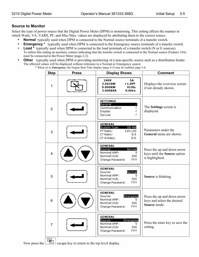
Source to Monitor Select the type of power source that the Digital Power Meter (DPM) is monitoring. This setting affects the manner in which Watts, VA, VARS, PF, and Min./Max. values are displayed by attributing them to the correct source.
Normal typically used when DPM is connected to the Normal source terminals of a transfer switch. Emergency * typically used when DPM is connected to the Emergency source terminals of a transfer switch. Load * typically used when DPM is connected to the load terminals of a transfer switch (N or E sources).
To utilize this setting an auxiliary contact indicating that the transfer switch is connected to the Normal source (Feature 14A) must be connected to the Power Meter (page 2-2).
Other typically used when DPM is providing monitoring of a non-specific source such as a distribution feeder. The effected values will be displayed without reference to a Normal or Emergency source.
* When set to Emergency, the Engine Run-Time display (page 4-3) may be enabled, page 3-8.
Step Press Display Shows Comment
1
Displays the overview screen if not already shown.
2
The Settings screen is displayed.
3
Parameters under the General menu are shown.
4
Press the up and down arrow keys until the Source option is highlighted.
5
Source is blinking.
6
Press the up and down arrow keys and select the desired Source mode.
7
Press the enter key to save the setting.
Now press the escape key to return to the top level display.
3-6 Initial Setup Operator’s Manual 381333-368G 5210 Digital Power Meter
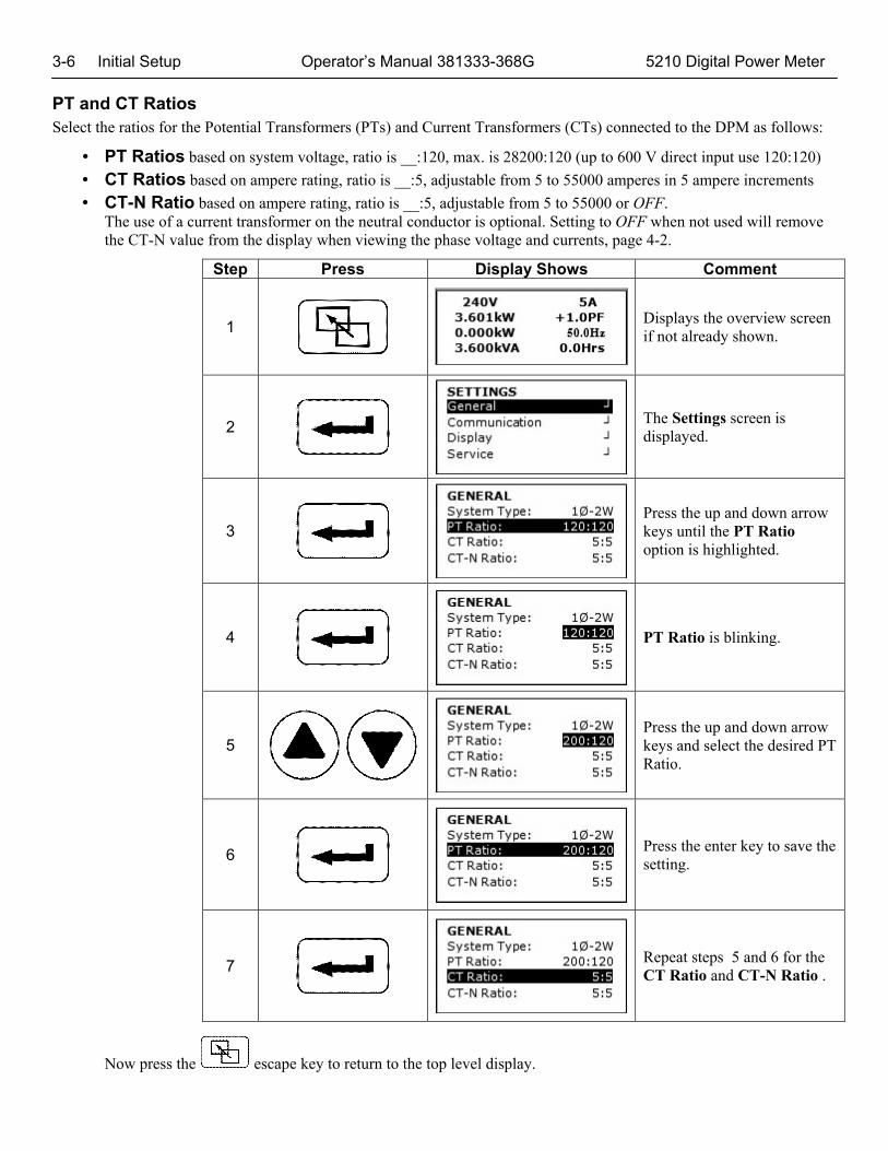
PT and CT Ratios Select the ratios for the Potential Transformers (PTs) and Current Transformers (CTs) connected to the DPM as follows:
PT Ratios based on system voltage, ratio is __:120, max. is 28200:120 (up to 600 V direct input use 120:120)
CT Ratios based on ampere rating, ratio is __:5, adjustable from 5 to 55000 amperes in 5 ampere increments
CT-N Ratio based on ampere rating, ratio is __:5, adjustable from 5 to 55000 or OFF. The use of a current transformer on the neutral conductor is optional. Setting to OFF when not used will remove the CT-N value from the display when viewing the phase voltage and currents, page 4-2.
Step Press Display Shows Comment
1
Displays the overview screen if not already shown.
2
The Settings screen is displayed.
3
Press the up and down arrow keys until the PT Ratio option is highlighted.
4
PT Ratio is blinking.
5
Press the up and down arrow keys and select the desired PT Ratio.
6
Press the enter key to save the setting.
7
Repeat steps 5 and 6 for the CT Ratio and CT-N Ratio .
Now press the escape key to return to the top level display.
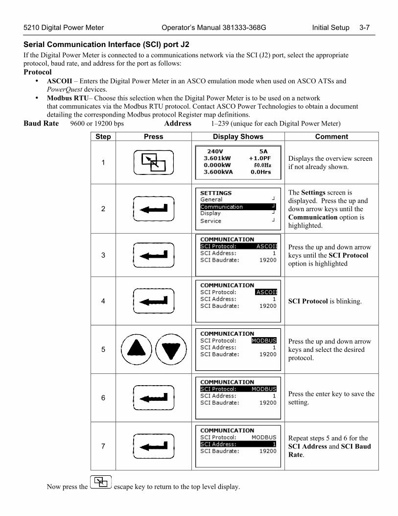
5210 Digital Power Meter Operator’s Manual 381333-368G Initial Setup 3-7 Serial Communication Interface (SCI) port J2 If the Digital Power Meter is connected to a communications network via the SCI (J2) port, select the appropriate protocol, baud rate, and address for the port as follows: Protocol
ASCOII – Enters the Digital Power Meter in an ASCO emulation mode when used on ASCO ATSs and PowerQuest devices.
Modbus RTU– Choose this selection when the Digital Power Meter is to be used on a network that communicates via the Modbus RTU protocol. Contact ASCO Power Technologies to obtain a document detailing the corresponding Modbus protocol Register map definitions.
Baud Rate 9600 or 19200 bps Address 1–239 (unique for each Digital Power Meter)
Step Press Display Shows Comment
1
Displays the overview screen if not already shown.
2
The Settings screen is displayed. Press the up and down arrow keys until the Communication option is highlighted.
3
Press the up and down arrow keys until the SCI Protocol option is highlighted
4
SCI Protocol is blinking.
5
Press the up and down arrow keys and select the desired protocol.
6
Press the enter key to save the setting.
7
Repeat steps 5 and 6 for the SCI Address and SCI Baud Rate.
Now press the escape key to return to the top level display.

3-8 Initial Setup Operator’s Manual 381333-368G 5210 Digital Power Meter RS485 Serial Communication Interface port J1 If the Digital Power Meter is connected to a communications network via the RS485 (J1) port, select the appropriate protocol, baud rate, and address for the port as follows: Protocol
ASCOII – Enters the Digital Power Meter in an ASCO I/O Module emulation mode when used on ASCO ATSs and PowerQuest devices.
Modbus RTU– Choose this selection when the Digital Power Meter is to be used on a network that communicates via the Modbus RTU protocol. Contact ASCO Power Technologies to obtain a document detailing the corresponding Modbus protocol Register map definitions.
Baud Rate 9600, 19200, 38400, 57600 bps Address 1–239 (unique for each Digital Power Meter)
Step Press Display Shows Comment
1
Displays the overview screen if not already shown.
2
The Settings screen is displayed. Press the up and down arrow keys until the Communication option is highlighted.
3
Press the up and down arrow keys until the 485 Protocol option is highlighted.
4
485 Protocol is blinking.
5
Press the up and down arrow keys and select the desired protocol.
6
Press the enter key to save the setting.
7
Repeat steps 5 and 6 for the 485 Address and 485 Baud Rate.
Now press the escape key to return to the top level display.

5210 Digital Power Meter Operator’s Manual 381333-368G Initial Setup 3-9 Engine Runtime Counter
When the Engine Runtime setting is set to ON and the Emergency source is monitored, the Engine Run-time display, page 4-3, will provide totalized hours of engine operation. For the Engine Run-Time display to be operational the Digital Power Meter (DPM) must be used as follows:
DPM connected to the Emergency source terminals of a transfer switch Engine Runtime setting must be set to ON, Source to Monitor setting, page 3-4, must be set to ON In this case the Runtime hours are totalized whenever at least 70 V L-L is present on the Voltage Inputs (TB1).
DPM connected to the Load terminals of a transfer switch Engine Runtime setting must be set to ON, Source to Monitor setting, page 3-4, must be set to Load. The ATS Position, page 3-9, must be set to ON and an auxiliary contact from the transfer switch must be connected to the DPM, page 2-2.
Step Press Display Shows Comment
1
Displays the overview screen if not already shown.
2
The Settings screen is displayed.
3
Parameters under the General menu are shown.
4
Press the up or down arrow keys until the Engine Run Time option is highlighted.
5
Engine Run Time is blinking.
6
Press the up or down arrow keys and select ON.
7
Press the enter key to save the setting.

3-10 Initial Setup Operator’s Manual 381333-368G 5210 Digital Power Meter
Clear Engine Runtime Counter
The Engine Runtime Counter can be reset as follows
Step Press Display Shows Comment
1
Displays the overview screen if not already shown.
2
The Settings screen is displayed.
3
Parameters under the General menu are shown.
4
Press the up and down arrow keys until the Clear Run Time option is highlighted.
5
Clear Run Time NO is blinking.
6
Press the up and down arrow keys and select YES.
7
The run time counter will be cleared and NO is shown again.
Now press the escape key to return to the top level display.

5210 Digital Power Meter Operator’s Manual 381333-368G Initial Setup 3-11
Clear Min Max Parameters
The Digital Power Meter maintains a record of minimum and maximum of various parameters since the last CLEAR Operation. These records can be cleared as follows:
Step Press Display Shows Comment
1
Displays the overview screen if not already shown.
2
The Settings screen is displayed.
3
Parameters under the General menu are shown.
4
Press the up and down arrow keys until the Clear MinMax option is highlighted.
5
Clear MinMax NO is blinking.
6
Press the up and down arrow keys and select YES.
7
The min max parameters will be cleared and NO is shown again
Now press the escape key to return to the top level display.
3-12 Initial Setup Operator’s Manual 381333-368G 5210 Digital Power Meter
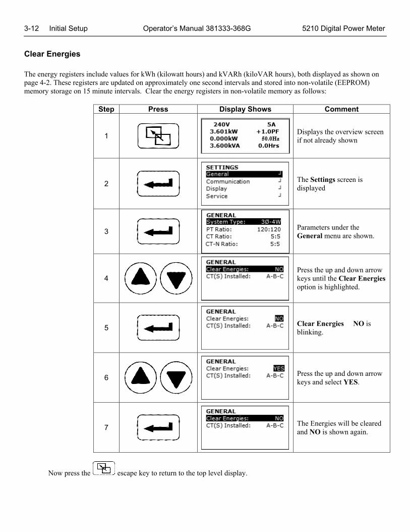
Clear Energies The energy registers include values for kWh (kilowatt hours) and kVARh (kiloVAR hours), both displayed as shown on page 4-2. These registers are updated on approximately one second intervals and stored into non-volatile (EEPROM) memory storage on 15 minute intervals. Clear the energy registers in non-volatile memory as follows:
Step Press Display Shows Comment
1
Displays the overview screen if not already shown
2
The Settings screen is displayed
3
Parameters under the General menu are shown.
4
Press the up and down arrow keys until the Clear Energies option is highlighted.
5
Clear Energies NO is blinking.
6
Press the up and down arrow keys and select YES.
7
The Energies will be cleared and NO is shown again.
Now press the escape key to return to the top level display.
5210 Digital Power Meter Operator’s Manual 381333-368G Initial Setup 3-13
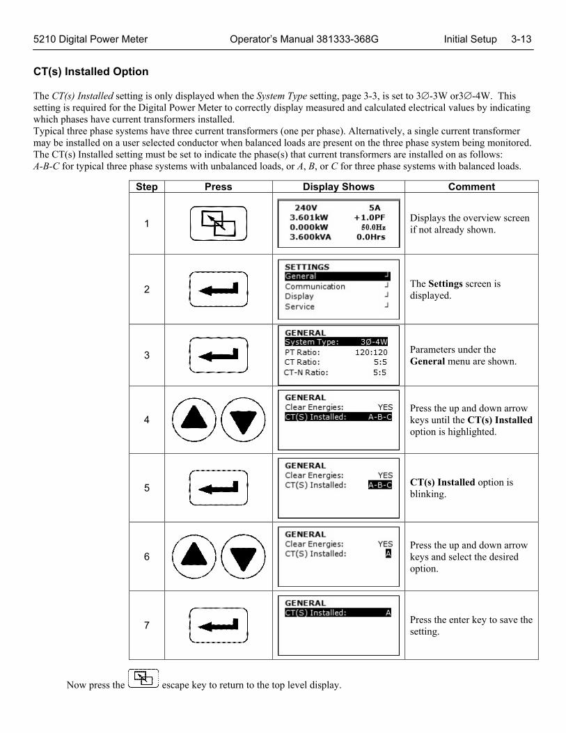
CT(s) Installed Option
The CT(s) Installed setting is only displayed when the System Type setting, page 3-3, is set to 3-3W or3-4W. This setting is required for the Digital Power Meter to correctly display measured and calculated electrical values by indicating which phases have current transformers installed. Typical three phase systems have three current transformers (one per phase). Alternatively, a single current transformer may be installed on a user selected conductor when balanced loads are present on the three phase system being monitored. The CT(s) Installed setting must be set to indicate the phase(s) that current transformers are installed on as follows: A-B-C for typical three phase systems with unbalanced loads, or A, B, or C for three phase systems with balanced loads.
Step Press Display Shows Comment
1
Displays the overview screen if not already shown.
2
The Settings screen is displayed.
3
Parameters under the General menu are shown.
4
Press the up and down arrow keys until the CT(s) Installed option is highlighted.
5
CT(s) Installed option is blinking.
6
Press the up and down arrow keys and select the desired option.
7
Press the enter key to save the setting.
Now press the escape key to return to the top level display.

3-14 Initial Setup Operator’s Manual 381333-368G 5210 Digital Power Meter
Language Selection The Digital Power Meter supports English, Spanish, Italian, French, German, Portuguese, Russian, Korean, and Chinese languages for display of screens and Menu Navigation in its normal runtime. The required language can be selected by navigating to the Display Settings Menu.
Step Press Display Shows Comment
1
Displays the overview screen if not already shown.
2
The Settings screen is displayed.
3
Press the up and down arrow keys until Display is highlighted.
4
Select the Language option.
5
Language option is blinking.
6
Press the up and down arrow keys and select the desired language option.
7
Press the enter key to save the setting.
Now press the escape key to return to the top level display.
5210 Digital Power Meter Operator’s Manual 381333-368G Initial Setup 3-15
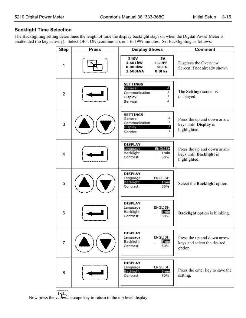
Backlight Time Selection The Backlighting setting determines the length of time the display backlight stays on when the Digital Power Meter is unattended (no key activity). Select OFF, ON (continuous), or 1 to 1999 minutes. Set Backlighting as follows:
Step Press Display Shows Comment
1
Displays the Overview Screen if not already shown
2
The Settings screen is displayed.
3
Press the up and down arrow keys until Display is highlighted.
4
Press the up and down arrow keys until Backlight is highlighted.
5
Select the Backlight option.
6
Backlight option is blinking.
7
Press the up and down arrow keys and select the desired option.
8
Press the enter key to save the setting.
Now press the escape key to return to the top level display.

3-16 Initial Setup Operator’s Manual 381333-368G 5210 Digital Power Meter
Contrast Selection The Digital Power Meter allows configuration of Contrast percentage of the LCD Display. The Contrast can be set to a value between 0 and 100 in steps of 10. Contrast can be configured by navigating to the Display Settings Menu.
Step Press Display Shows Comment
1
Displays the overview screen if not already shown.
2
The Settings screen is displayed.
3
Press the up and down arrow keys until Display is highlighted.
4
Press the up and down arrow keys until Contrast is highlighted.
5
Select the Contrast option.
6
Contrast option is blinking.
7
Press the up and down arrow keys and select the desired percentage.
8
Press the enter key to save the setting.
Now press the escape key to return to the top level display.
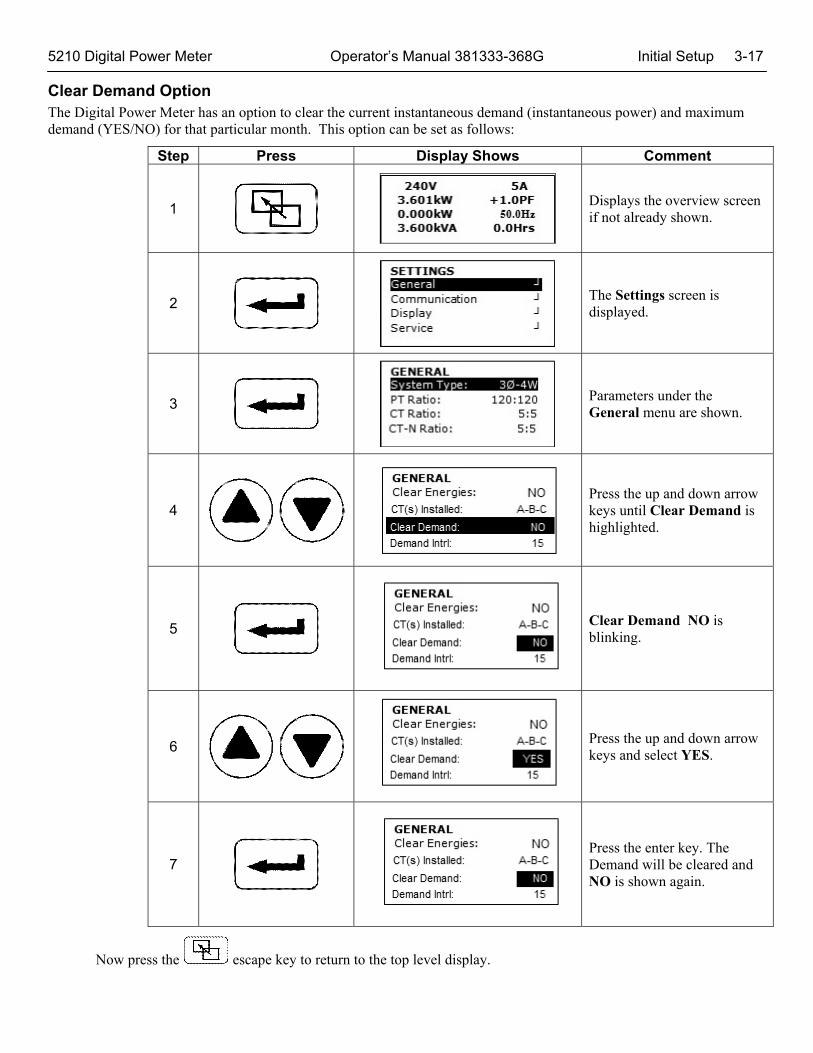
5210 Digital Power Meter Operator’s Manual 381333-368G Initial Setup 3-17 Clear Demand Option The Digital Power Meter has an option to clear the current instantaneous demand (instantaneous power) and maximum demand (YES/NO) for that particular month. This option can be set as follows:
Step Press Display Shows Comment
1
Displays the overview screen if not already shown.
2
The Settings screen is displayed.
3
Parameters under the General menu are shown.
4 Press the up and down arrow keys until Clear Demand is highlighted.
5
Clear Demand NO is blinking.
6 Press the up and down arrow keys and select YES.
7
Press the enter key. The Demand will be cleared and NO is shown again.
Now press the escape key to return to the top level display.

3-18 Initial Setup Operator’s Manual 381333-368G 5210 Digital Power Meter Demand Interval Option The Digital Power Meter has an option to configure the Demand Integration period (1 to 15). This option can be set as follows:
Step Press Display Shows Comment
1
Displays the overview screen if not already shown.
2
The Settings screen is displayed.
3
Parameters under the General menu are shown.
4 Press the up and down arrow keys until Demand Intrl is highlighted.
5
Demand Intrl 15 is blinking.
6 Press the up and down arrow keys and select the desired interval.
7
Press the enter key to save the setting.
Now press the escape key to return to the top level display.
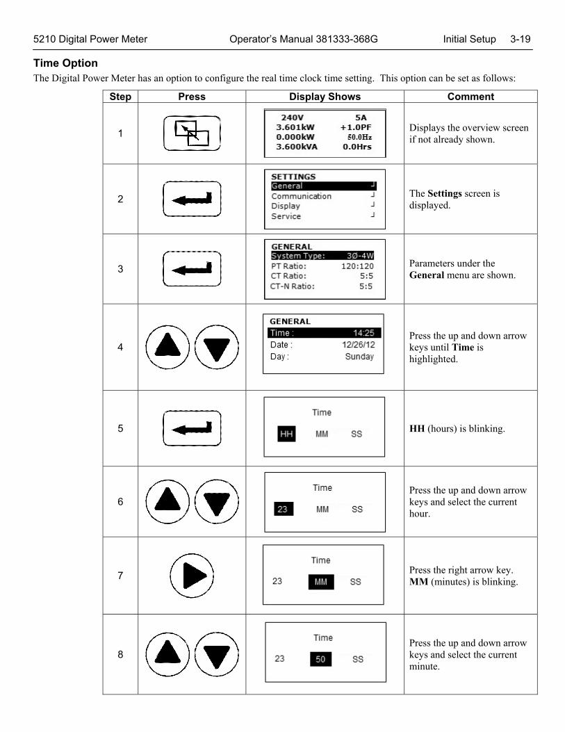
5210 Digital Power Meter Operator’s Manual 381333-368G Initial Setup 3-19 Time Option The Digital Power Meter has an option to configure the real time clock time setting. This option can be set as follows:
Step Press Display Shows Comment
1
Displays the overview screen if not already shown.
2
The Settings screen is displayed.
3
Parameters under the General menu are shown.
4 Press the up and down arrow keys until Time is highlighted.
5
HH (hours) is blinking.
6 Press the up and down arrow keys and select the current hour.
7
Press the right arrow key. MM (minutes) is blinking.
8 Press the up and down arrow keys and select the current minute.
3-20 Initial Setup Operator’s Manual 381333-368G 5210 Digital Power Meter
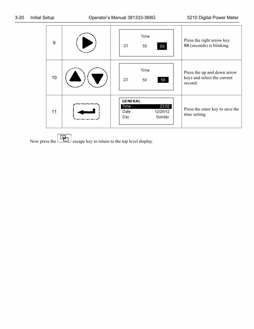
9
Press the right arrow key. SS (seconds) is blinking.
10 Press the up and down arrow keys and select the current second.
11
Press the enter key to save the time setting.
Now press the escape key to return to the top level display.

5210 Digital Power Meter Operator’s Manual 381333-368G Initial Setup 3-21 Date Option The Digital Power Meter has an option to configure the real time clock date setting. This option can be set as follows:
Step Press Display Shows Comment
1
Displays the overview screen if not already shown.
2
The Settings screen is displayed.
3
Parameters under the General menu are shown.
4 Press the up and down arrow keys until Date is highlighted.
Date Format can be set for US (MM DD YY), EU (DD MM YY), or ISO (YY MM DD). The setting process is similar but in different month, day, year order. US format is shown here.
5
MM (month) is blinking.
6 Press the up and down arrow keys and select the current month.
7
Press the right arrow key. DD (day of the month) is blinking.
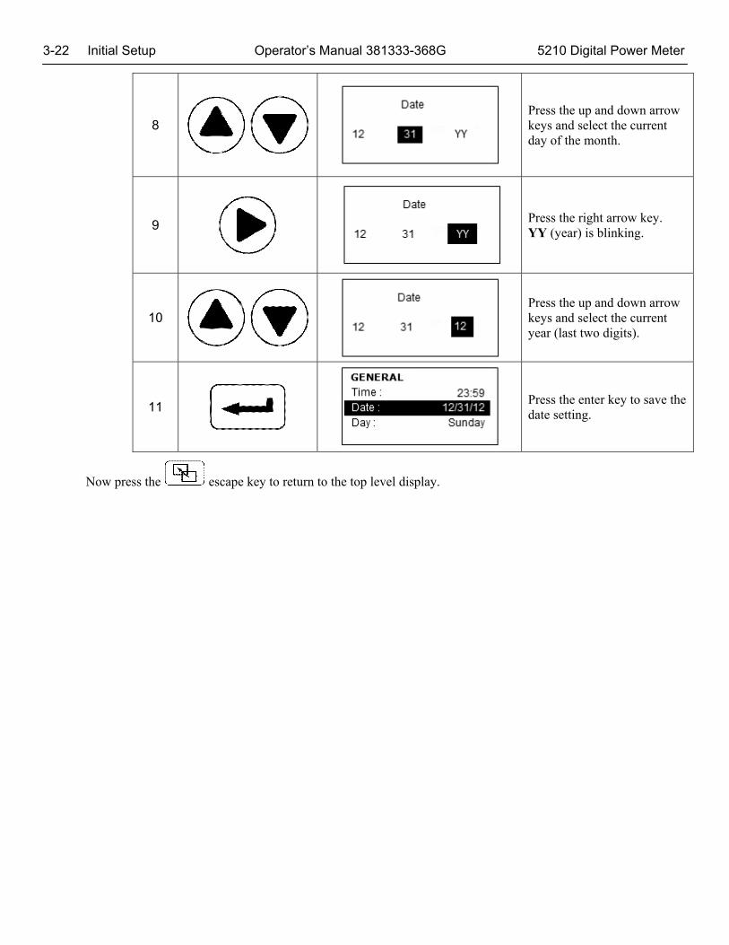
3-22 Initial Setup Operator’s Manual 381333-368G 5210 Digital Power Meter
8 Press the up and down arrow keys and select the current day of the month.
9
Press the right arrow key. YY (year) is blinking.
10 Press the up and down arrow keys and select the current year (last two digits).
11
Press the enter key to save the date setting.
Now press the escape key to return to the top level display.
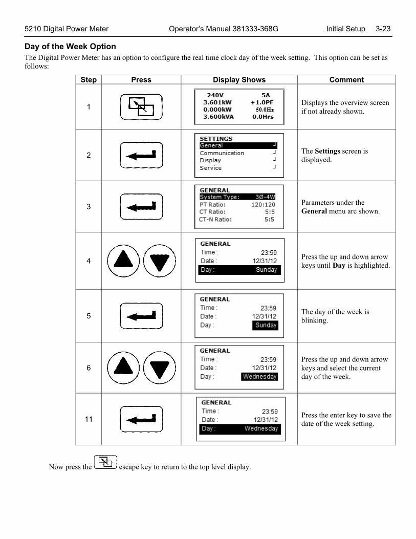
5210 Digital Power Meter Operator’s Manual 381333-368G Initial Setup 3-23 Day of the Week Option The Digital Power Meter has an option to configure the real time clock day of the week setting. This option can be set as follows:
Step Press Display Shows Comment
1
Displays the overview screen if not already shown.
2
The Settings screen is displayed.
3
Parameters under the General menu are shown.
4 Press the up and down arrow keys until Day is highlighted.
5
The day of the week is blinking.
6 Press the up and down arrow keys and select the current day of the week.
11
Press the enter key to save the date of the week setting.
Now press the escape key to return to the top level display.

4-1 Operation Operator’s Manual 381333-368G 5210 Digital Power Meter
Unit of Powers is dynamically updated depending on the range
480V 1000 A 480 kW +1.00 PF 0 kVAR 60.0 Hz 480 kVA 100.0 Hrs
Operation From the top level display the Digital Power Meter can show the following information about the electrical power system:
System totals (kW, kVAR, kVA, PF, Hz, position of ATS) Current and Voltage (line–to–neutral & line–to–line) – all phases Power (kW), kVARs, kVA, & PF (power factor) – all phases Average current & voltage (line–to–neutral & line–to–line) Unbalance % amps & voltage (line–to–neutral & line–to–line) Neutral current (if neutral is connected to Digital Power Meter) kW hours (imp, exp, net) for Normal & Emergency sources kVAR hours (lag, lead, net) for Normal & Emergency sources
Data is updated approximately every second. As the default screen, the following screen shows the overview of the system
Average Line to Line voltage
Net Active Power
Net Reactive Power
Net Apparent Power
Average Phase Current
Net Power Factor
Line frequency
Total Engine Runtime in hours OR ATS Position
• ATS position is displayed if Source is selected as ‘LOAD’
• Engine Run-time is displayed if Source is selected as ‘Other’ and Engine Run-time counter is enabled
• Blank if not ‘LOAD’ and Engine Run Time Counter Disabled

4-2
O
pera
tion
O
pera
tor’s
Man
ual 3
8133
3-36
8G
5
210
Dig
ital P
ower
Met
er
Op
erat
ion
Scr
een
s N
avig
atio
n
480V
1000
A
480
kW
+1.
00 P
F
0 kV
AR
60.
0 H
z 48
0 kV
A 1
00.0
Hrs
Ø V
-LN
V-L
L A
MP
S
A
0
0
0
B
0
0
0
C
0
0
0
C
T-N
0
Ø
WA
TT
S
P
F
A
0
0
B
0
0
C
0
0
T
otal
0
Ø
VA
s
VA
Rs
A
0
0
B
0
0
C
0
0
T
otal
0
kWh
- N
orm
al
IMP
OR
T >
0
E
XP
OR
T >
0
N
ET
>
0
kWh
- E
mer
gen
cy
IMP
OR
T >
0
E
XP
OR
T >
0
N
ET
>
0
% F
ull
Lo
ad
Ø
AM
Ps
W
AT
Ts
A
0
%
0
%
B
0
%
0
%
C
0
%
0
%
A
VG
U
NB
AL
A
MP
s
0
0%
V
-LL
0
0%
V
-LN
0
0%
kVA
rh -
No
rmal
LA
G
>
0
LE
AD
>
0
NE
T
>
0
kV
Ah
>
0
kVA
rh -
Em
erg
enc
y LA
G
>
0
LE
AD
>
0
NE
T
>
0
kV
Ah
>
0
Em
erg
. M
in.
Max
. V
-LL
0
0
AM
Ps
0
0
H
z
0
0
Max
kW
Su
mm
ary
Last
60
Min
0
kW
Last
24
Hr
0
kW
La
st 3
0 D
ay
0
kW
La
st 1
2 M
onth
0
kW
Mo
nth
ly M
ax D
eman
d20
14
2013
Ja
n 0
kW
0 kW
F
eb
0 kW
0
kW
Mar
0 kW
0 kW
Em
erg
. M
in.
Max
. W
AT
Ts
0
0
VA
s
0
0
V
AR
s
0
0
PF
0
0
Max
Dem
and
Det
ails
La
st In
terv
al (
10M
ins)
0
kW
Dat
e @
tim
e (I
nsta
ntan
eous
)
over
vie
w s
cree
n C
ontin
ues
on n
ext r
ow
Con
tinue
s on
nex
t ro
w
En
gin
e R
un
-Tim
e
Res
etta
ble:
0
Hrs
C
umul
ativ
e:
0 H
rs
Mo
nth
ly M
ax D
eman
d20
14
2013
A
pr
0 kW
0
kW
May
0
kW
0 kW
Ju
n 0
kW
0 kW
VO
LT
AG
E T
HD
Ø
% T
HD
A
>
>
0.00
B
>
>
0.00
B
>
>
0.00
Dem
and
Det
ails
co
ntin
ued
Max
Dem
and
cont
inue
d
No
rmal
M
in.
Max
. V
-LL
0
0
AM
Ps
0
0
H
z
0
0
No
rmal
M
in.
Max
. W
AT
Ts
0
0
VA
s
0
0
V
AR
s
0
0
PF
0
0
CU
RR
EN
T T
HD
Ø
% T
HD
A
>
>
0.00
B
>
>
0.00
B
>
>
0.00
Wat
t D
eman
d
INS
T:
0
kW
MA
X:
0
kW
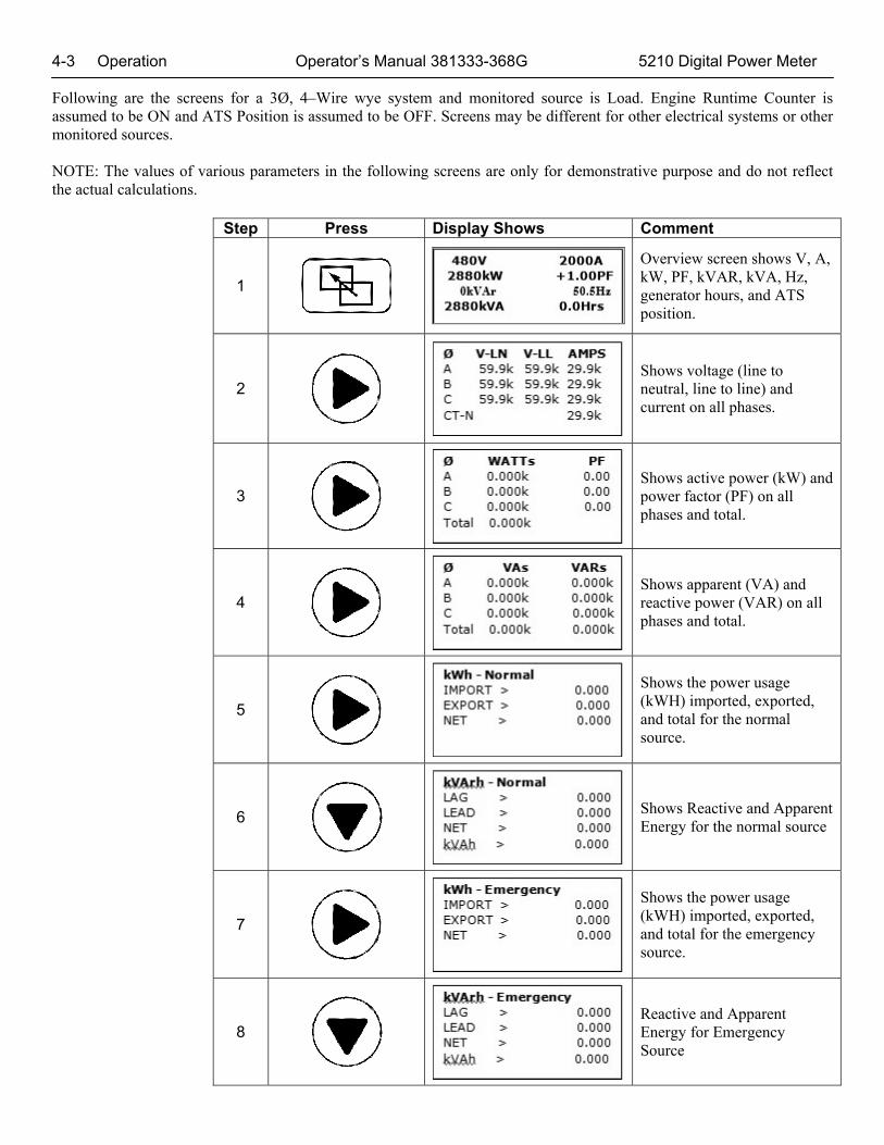
4-3 Operation Operator’s Manual 381333-368G 5210 Digital Power Meter Following are the screens for a 3Ø, 4–Wire wye system and monitored source is Load. Engine Runtime Counter is assumed to be ON and ATS Position is assumed to be OFF. Screens may be different for other electrical systems or other monitored sources. NOTE: The values of various parameters in the following screens are only for demonstrative purpose and do not reflect the actual calculations.
Step Press Display Shows Comment
1
Overview screen shows V, A, kW, PF, kVAR, kVA, Hz, generator hours, and ATS position.
2
Shows voltage (line to neutral, line to line) and current on all phases.
3
Shows active power (kW) and power factor (PF) on all phases and total.
4
Shows apparent (VA) and reactive power (VAR) on all phases and total.
5
Shows the power usage (kWH) imported, exported, and total for the normal source.
6
Shows Reactive and Apparent Energy for the normal source
7
Shows the power usage (kWH) imported, exported, and total for the emergency source.
8
Reactive and Apparent Energy for Emergency Source

5210 Digital Power Meter Operator’s Manual 381333-368G Operation 4-4
9
% Full Load
10
Shows average current and voltage (line to line, line to neutral) and percent unbalanced.
11
Shows the minimum and maximum voltage, current, and frequency for the normal source.
12
Shows the minimum and maximum kW, VA, VAR, and PF for the normal source.
13
Shows the minimum and maximum voltage, current, and frequency for the emergency source.
14
Shows the minimum and maximum kW, VA, VAR, and PF for the emergency source.
15
Shows the load demand in the past 60 min, 24 hours, 30 days, and 12 months.
16
Shows more load demand details in past 10 minutes, 60 minutes, 24 hours, 30 days, and 12 months. Press the down arrow for the next interval.
17
Shows a comparison of monthly load demand this year versus last year. Press the down arrow for the next three months.
Max kW Summary Last 60 Min 0 kW Last 24 Hr 0 kW Last 30 Day 0 kW Last 12 Month 0 kW
Max Demand Details Last Interval (10Mins)
0 kW Date @ time
(Instantaneous)
Monthly Max Demand2014 2013
Jan 0 kW 0 kW Feb 0 kW 0 kW Mar 0 kW 0 kW
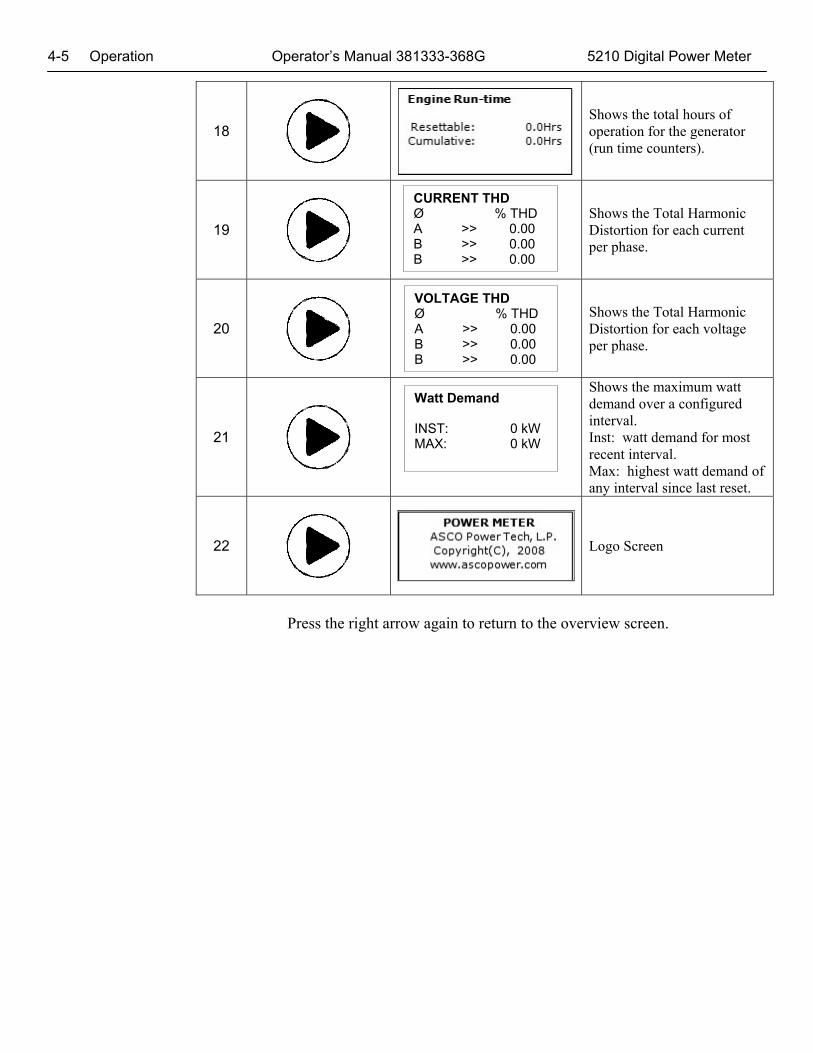
4-5 Operation Operator’s Manual 381333-368G 5210 Digital Power Meter
18
Shows the total hours of operation for the generator (run time counters).
19
Shows the Total Harmonic Distortion for each current per phase.
20
Shows the Total Harmonic Distortion for each voltage per phase.
21
Shows the maximum watt demand over a configured interval. Inst: watt demand for most recent interval. Max: highest watt demand of any interval since last reset.
22
Logo Screen
Press the right arrow again to return to the overview screen.
CURRENT THD Ø % THD A >> 0.00 B >> 0.00 B >> 0.00
VOLTAGE THD Ø % THD A >> 0.00 B >> 0.00 B >> 0.00
Watt Demand INST: 0 kW MAX: 0 kW

App
endi
x 1-
1
Wiri
ng D
iagr
ams
Ope
rato
r’s M
anua
l 381
333-
368F
5210
Pow
er M
eter
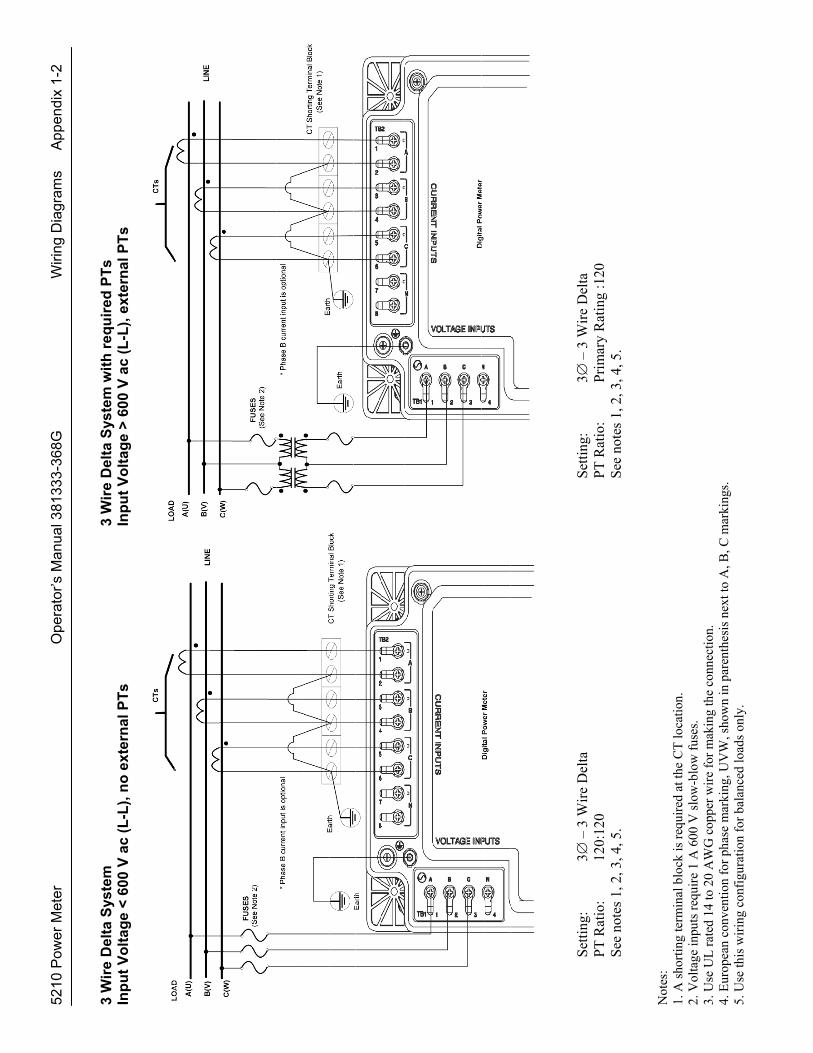
2
Wir
e S
ing
le P
has
e
3 W
ire
Sin
gle
Ph
ase
Inp
ut
Vo
ltag
e <
600
V a
c (L
-L),
no
ext
ern
al P
Ts
In
pu
t V
olt
age
< 6
00 V
ac
(L-L
), n
o e
xter
nal
PT
s
S
etti
ng:
1 –
2 W
ire
Set
ting
: 1
– 3
Wir
e P
T R
atio
: 12
0:12
0
P
T R
atio
: 12
0:12
0 S
ee n
otes
1, 2
, 3.
S
ee n
otes
1, 2
, 3.
Not
es:
1. A
sho
rtin
g te
rmin
al b
lock
is r
equi
red
at th
e C
T lo
catio
n.
2. V
olta
ge in
puts
req
uire
1 A
600
V s
low
-blo
w f
uses
. 3.
Use
UL
rat
ed 1
4 to
20
AW
G c
oppe
r w
ire
for
mak
ing
the
conn
ectio
n.
4. F
uses
(s)
shou
ld b
e in
stal
led
on a
ll “h
ot”
volta
ge in
puts
.
5210
Pow
er M
eter
O
pera
tor’s
Man
ual 3
8133
3-36
8G
Wiri
ng D
iagr
ams
A
ppen
dix
1-2
3 W
ire
Del
ta S
yste
m
3 W
ire
Del
ta S
yste
m w
ith
req
uir
ed P
Ts
Inp
ut
Vo
ltag
e <
600
V a
c (L
-L),
no
ext
ern
al P
Ts
In
pu
t V
olt
age
> 6
00 V
ac
(L-L
), e
xter
nal
PT
s
S
etti
ng:
3 –
3 W
ire
Del
ta
S
etti
ng:
3 –
3 W
ire
Del
ta
PT
Rat
io:
120:
120
PT
Rat
io:
Pri
mar
y R
atin
g :1
20
See
not
es 1
, 2, 3
, 4, 5
.
See
not
es 1
, 2, 3
, 4, 5
. N
otes
: 1.
A s
hort
ing
term
inal
blo
ck is
req
uire
d at
the
CT
loca
tion.
2.
Vol
tage
inpu
ts r
equi
re 1
A 6
00 V
slo
w-b
low
fus
es.
3. U
se U
L r
ated
14
to 2
0 A
WG
cop
per
wir
e fo
r m
akin
g th
e co
nnec
tion.
4.
Eur
opea
n co
nven
tion
for
phas
e m
arki
ng, U
VW
, sho
wn
in p
aren
thes
is n
ext t
o A
, B, C
mar
king
s.
5. U
se th
is w
irin
g co
nfig
urat
ion
for
bala
nced
load
s on
ly.
App
endi
x 1-
3
Wiri
ng D
iagr
ams
Ope
rato
r’s M
anua
l 381
333-
368G
5210
Pow
er M
eter
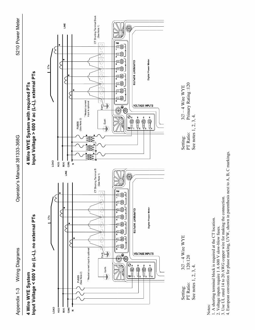
4
Wir
e W
YE
Sys
tem
4
Wir
e W
YE
Sys
tem
wit
h r
equ
ired
PT
s In
pu
t V
olt
age
< 6
00 V
ac
(L-L
), n
o e
xter
nal
PT
s
Inp
ut
Vo
ltag
e >
600
V a
c (L
-L),
ext
ern
al P
Ts
S
etti
ng:
3 –
4 W
ire
WY
E
S
etti
ng:
3 –
4 W
ire
WY
E
PT
Rat
io:
120:
120
PT
Rat
io:
Pri
mar
y R
atin
g :1
20
See
not
es 1
, 2, 3
, 4.
S
ee n
otes
1, 2
, 3, 4
. N
otes
: 1.
A s
hort
ing
term
inal
blo
ck is
req
uire
d at
the
CT
loca
tion.
2.
Vol
tage
inpu
ts r
equi
re 1
A 6
00 V
slo
w-b
low
fus
es.
3. U
se U
L r
ated
14
to 2
0 A
WG
cop
per
wir
e fo
r m
akin
g th
e co
nnec
tion.
4.
Eur
opea
n co
nven
tion
for
phas
e m
arki
ng, U
VW
, sho
wn
in p
aren
thes
is n
ext t
o A
, B, C
mar
king
s.
5210
Pow
er M
eter
O
pera
tor’s
Man
ual 3
8133
3-36
8G
Wiri
ng D
iagr
ams
A
ppen
dix
1-4
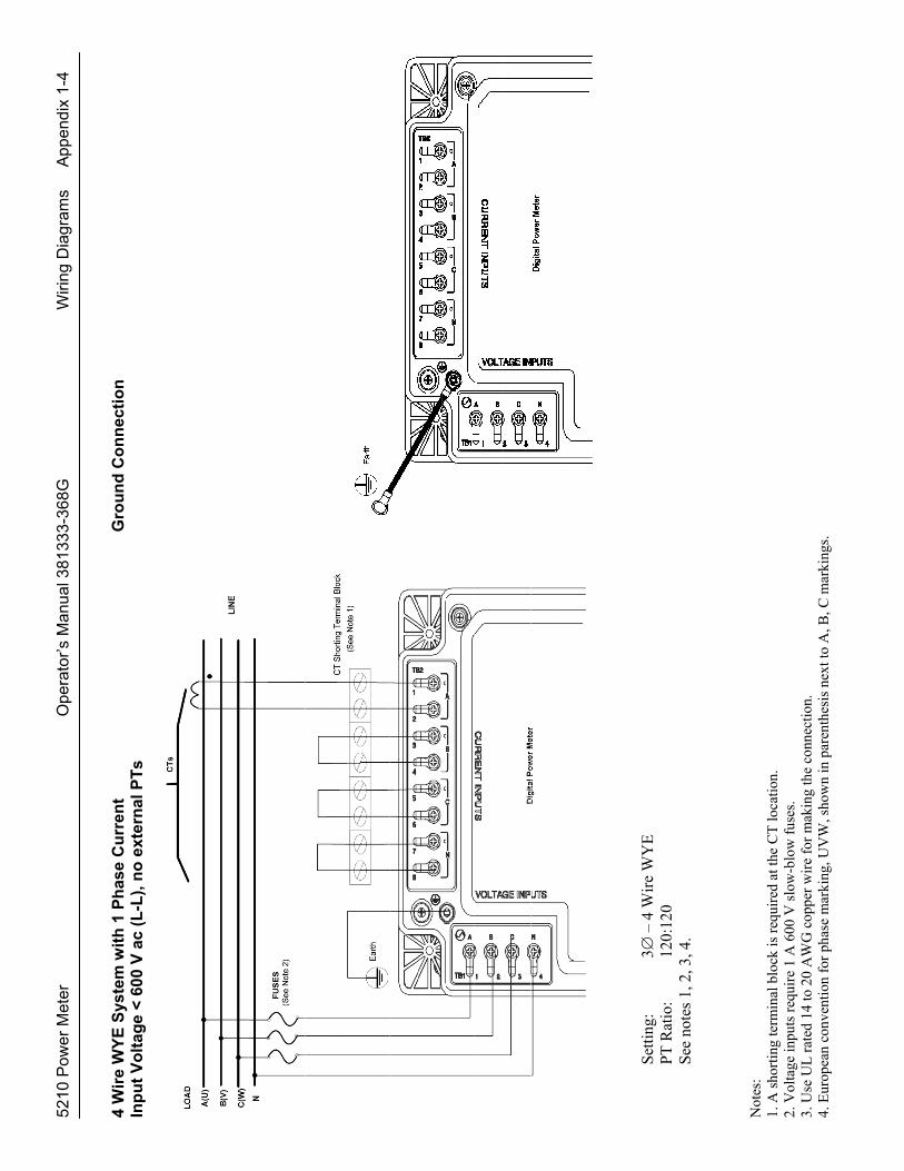
4 W
ire
WY
E S
yste
m w
ith
1 P
has
e C
urr
ent
Gro
un
d C
on
nec
tio
n
Inp
ut
Vo
ltag
e <
600
V a
c (L
-L),
no
ext
ern
al P
Ts
Set
ting
: 3
– 4
Wir
e W
YE
PT
Rat
io:
120:
120
See
not
es 1
, 2, 3
, 4.
N
otes
: 1.
A s
hort
ing
term
inal
blo
ck is
req
uire
d at
the
CT
loca
tion.
2.
Vol
tage
inpu
ts r
equi
re 1
A 6
00 V
slo
w-b
low
fus
es.
3. U
se U
L r
ated
14
to 2
0 A
WG
cop
per
wir
e fo
r m
akin
g th
e co
nnec
tion.
4.
Eur
opea
n co
nven
tion
for
phas
e m
arki
ng, U
VW
, sho
wn
in p
aren
thes
is n
ext t
o A
, B, C
mar
king
s.

App
endi
x 1-
5
Wiri
ng D
iagr
ams
Ope
rato
r’s M
anua
l 381
333-
368G
5210
Pow
er M
eter
R
S48
5 4-
Wir
e M
od
e
&
AT
S a
uxi
liar
y co
nta
ct
con
nec
tio
n
AP
AC
1
AP
AC
2
AP
AC
5210
Pow
er M
eter
O
pera
tor’s
Man
ual 3
8133
3-36
8G
Wiri
ng D
iagr
ams
A
ppen
dix
1-6
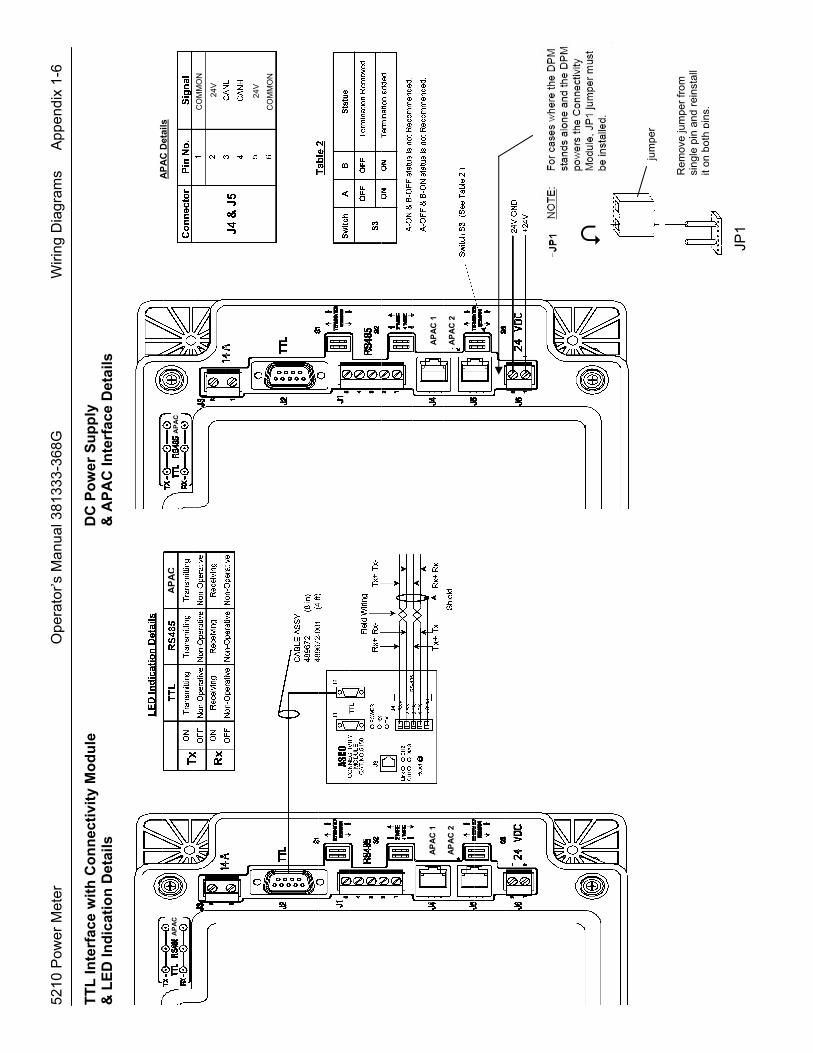
TT
L In
terf
ace
wit
h C
on
nec
tivi
ty M
od
ule
D
C P
ow
er S
up
ply
&
LE
D In
dic
atio
n D
etai
ls
& A
PA
C In
terf
ace
Det
ails
AP
AC
1
AP
AC
2
AP
AC
1
AP
AC
2
CO
MM
ON
CO
MM
ON
24
V
24
V
AP
AC
AP
AC
Det
ail
s
AP
AC
A
PA
C
JP1
jum
per
Rem
ove
jum
per
from
si
ngle
pin
and
rei
nsta
ll it
onbo
thpi
ns.
App
endi
x 1-
7
Wiri
ng D
iagr
ams
Ope
rato
r’s M
anua
l 381
333-
368G
5210
Pow
er M
eter
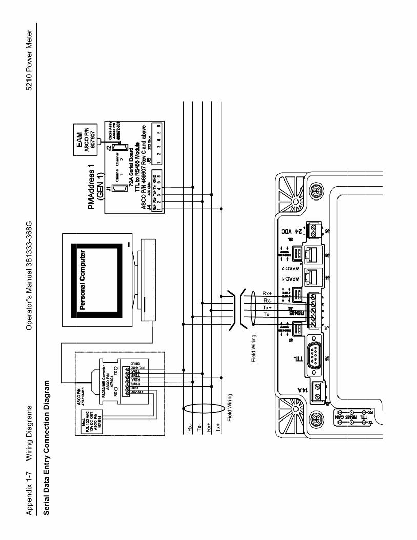
S
eria
l Dat
a E
ntr
y C
on
nec
tio
n D
iag
ram

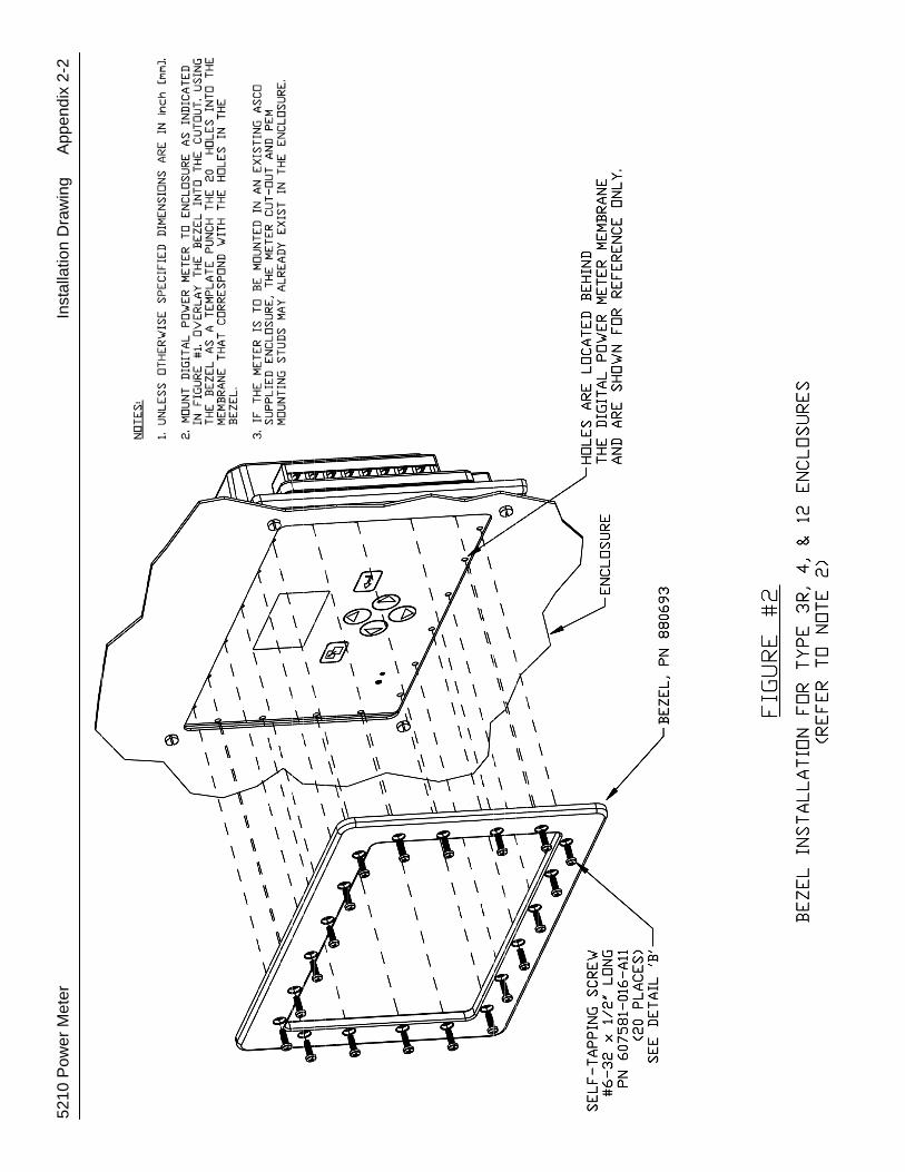
App
endi
x 2-
1
Inst
alla
tion
Dra
win
g
521
0 P
ower
Met
er
5210
Pow
er M
eter
Inst
alla
tion
Dra
win
g
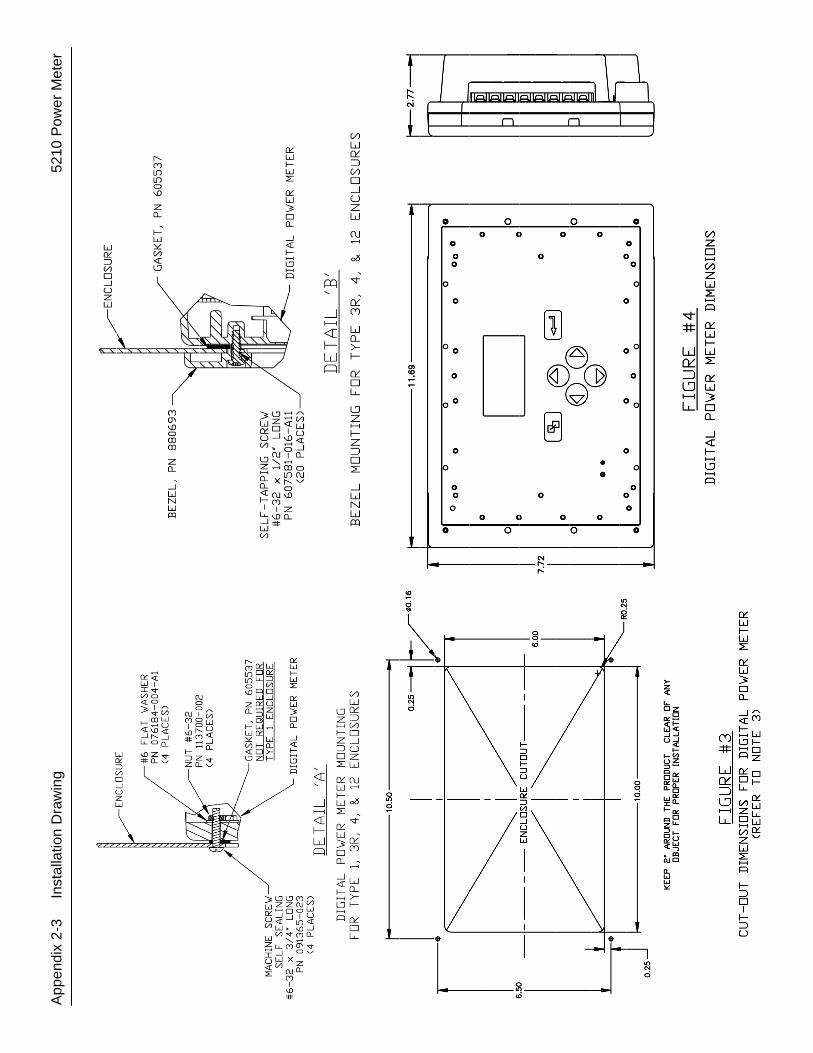
App
endi
x 2-
2
App
endi
x 2-
3
Inst
alla
tion
Dra
win
g
5
210
Pow
er M
eter


Printed in U.S.A. © ASCO Power Technologies, L.P. 2015 All Rights Reserved.
INDEX
A ac power supply, 2-2 accessory 72E, 2-3 accuracy, 1-3 active power, 4-1 address, 3-7, 3-8 apparent power, 4-1 arrow keys, 3-1 ASCOBUS II, 3-7, 3-8 ATS position, 2-2, 4-1 auxiliary contact, 2-2 average current & voltage, 4-1
B Backlight time selection, 3-16 baud rate, 3-7, 3-8 buttons (arrows, enter, escape), 3-1
C cable, communication, 2-3 change password, 3-3 clear energies, 3-13 Clear Demand, 3-18 Clear Run-Time counter, 3-11 Clear Min Max parameters, 3-12 clock (real time) setting
Date (mm, dd, yy), 3-22, 3-23 Day (of the week), 3-24 Time (hh, mm, ss), 3-20, 3-21
Communication, 3-2, 3-7, 3-8 connections, 2-1, appendix 1 Connectivity Module, 2-3 Contrast selection, 3-17 control overview, 3-1 current, 1-4, 4-1 CT current transformers,
2-2, 3-6, 3-14, appendix 1 DANGER statement, 2-1, 2-2
D DANGER statements, cover, 2-1 Date (mm, dd, yy), 3-22, 3-23 Date Format (US, EU, ISO), 3-21 Day (of the week), 3-24 Demand, clear, 3-18 Demand Intrl (Interval), 3-19 device ratings, 1-4 display, 4-1, 4-2, 4-3 Display, 3-2, 3-15, 3-16, 3-17
E electrical system type,
3-4, appendix 1
engine runtime counter, 3-9, 3-11 emergency source, 3-5 energy registers, 3-13 enter key, escape key, 3-1
F Feature 14A, 2-2 frequency, 1-3, 1-4, 4-1
G General settings, 3-3
Clear Demand, 3-18 CT Ratio, 3-6 CT-N Ratio, 3-6 Date (mm, dd, yy), 3-22, 3-23 Day (of the week), 3-24 Demand Intrl (interval), 3-19 PT Ratio, 3-6 System Type, 3-4 Time (hh, mm, ss), 3-20, 3-21
general information, 1-1 ground connection, 2-2
H HELP 800-800-2726(ASCO)
I initial setup, 3-1 inputs, 1-4, appendix 1 installation, 2-1, appendix 2 interval, demand, 3-19
J J1 (RS-485), J2 (serial), 2-3 J3, transfer switch position, 2-2 J6, dc power supply, 2-2 JP1 jumper, appendix 1-6
K kW, kVA, kVAR, 1-2, 3-1, 4-1, 4-2
L Language selection, 3-15 load source to monitor, 3-5
M measurements, 1-1, 1-2, 1-3 Modbus RTU, 3-7 mounting, 1-4, 2-1, appendix 2
N net power, 4-1 neutral current, 4-1
normal source, 3-5
O operation, 4-1 other source to monitor, 3-5 overview, 3-1 overview screen, 3-4, 4-1, 4-2
P parameters, 1-3 password selection, 3-3 ports, 3-7, 3-8 power, power factor, 4-1 power supply, 1-4, 2-2, appendix 1 protocol, 2-3, 3-7, 3-8 PT potential transformer,
3-6, Appendix 1
R ratings, 1-4 RS-485, 3-8, appendix 1
S SCI serial communication interface,
3-7, 3-8 Settings, 3-2
General, 3-3 Communication, 3-7, 3-8 Display, 3-15
setup, initial, 3-1 Source (to monitor), 2-2, 3-5 specifications, measurement, 1-3 System Type, 3-1, 3-4
T temperature, 1-4 Time (hh, mm, ss), 3-20, 3-21 total harmonic distortion THD, 4-2 transfer switch, 2-2, 3-5, 3-10 TTL interface, appendix 1
U unbalance current & voltage, 4-1
V voltage, 1-3, 4-1 voltage connection, 2-2, appendix 1
W Watts, 1-2, 1-3 wiring diagrams, appendix 1