table of contents - orolia · connectivity to the reference time source. the...
TRANSCRIPT

Table of Contents
Part I Overview 5
................................................................................................................................... 51 What is PresenTense Server
................................................................................................................................... 72 Network Time Synchronization
................................................................................................................................... 83 Time Protocols & Accuracy
................................................................................................................................... 84 Which Time Protocol is Right for Me ?
................................................................................................................................... 95 GPS Time Synchronization
................................................................................................................................... 106 Free Run Support
................................................................................................................................... 137 Standard Deviation Statistical Filter
................................................................................................................................... 138 System Requirements
................................................................................................................................... 139 FAQ
Part II Configuration 14
................................................................................................................................... 141 Admin Tab
................................................................................................................................... 152 Settings Tab
................................................................................................................................... 163 Internet Time Server Tab
................................................................................................................................... 174 Handheld GPS Tab
................................................................................................................................... 185 NTP4+GPS Tab
................................................................................................................................... 226 NMEA Tab
................................................................................................................................... 237 Performance Tab
................................................................................................................................... 248 Log Tab
................................................................................................................................... 249 NTP4 Key Generator
................................................................................................................................... 2510 NTP4 Plug-In Drivers
................................................................................................................................... 2611 Undisciplined Local Clock
................................................................................................................................... 2612 NTP4 Plug-In Driver Calibration
................................................................................................................................... 2813 NTP4 Plug-In Driver Troubleshooting
Part III Hardware 29
................................................................................................................................... 291 TripNav TN-200
................................................................................................................................... 302 Generic NMEA GPS
................................................................................................................................... 303 Hand Held GPS Receivers
................................................................................................................................... 314 GPS Parts List
................................................................................................................................... 325 Arbiter
................................................................................................................................... 346 Spectracom Clock Formats
................................................................................................................................... 357 Spectracom
................................................................................................................................... 388 Hopf DCF77/GPS PCI-Bus Receiver
IContents
I
© 1999-2003 Bytefusion Ltd
................................................................................................................................... 409 Hopf 6870 & Compatibles
................................................................................................................................... 4210 Ultralink
Part IV RFC 868 43
................................................................................................................................... 431 RFC 868
Part V RFC 2030 44
................................................................................................................................... 441 RFC 2030
Part VI RFC 1305 56
................................................................................................................................... 561 RFC 1305
................................................................................................................................... 622 1. Introduction
................................................................................................................................... 633 1.1 Related Technology
................................................................................................................................... 664 2. System Architecture
................................................................................................................................... 675 2.1 Implementation Model
................................................................................................................................... 686 2.2 Network Configurations
................................................................................................................................... 707 3. Network Time Protocol
................................................................................................................................... 708 3.1 Data Formats
................................................................................................................................... 719 3.2 State Variables and Parameters
................................................................................................................................... 7110 3.2.1 Common Variables
................................................................................................................................... 7411 3.2.2 System Variables
................................................................................................................................... 7512 3.2.3 Peer Variables
................................................................................................................................... 7813 3.2.4 Packet Variables
................................................................................................................................... 7914 3.2.5 Clock-Filter Variables
................................................................................................................................... 7915 3.2.6 Authentication Variables
................................................................................................................................... 8016 3.2.7 Parameters
................................................................................................................................... 8217 3.3 Modes of Operation
................................................................................................................................... 8318 3.4 Event Processing
................................................................................................................................... 8319 3.4.1 Notation Conventions
................................................................................................................................... 8520 3.4.2 Transmit Procedure
................................................................................................................................... 8721 3.4.3 Receive Procedure
................................................................................................................................... 8922 3.4.4 Packet Procedure
................................................................................................................................... 9123 3.4.5 Clock-Update Procedure
................................................................................................................................... 9324 3.4.6 Primary-Clock Procedure
................................................................................................................................... 9325 3.4.7 Initialization Procedures
................................................................................................................................... 9326 3.4.7.1 Initialization Procedure
................................................................................................................................... 9427 3.4.7.2 Initialization-Instantiation Procedure
................................................................................................................................... 9528 3.4.7.3 Receive-Instantiation Procedure
................................................................................................................................... 9529 3.4.7.4 Primary Clock-Instantiation Procedure
................................................................................................................................... 9630 3.4.8 Clear Procedure
PresenTense ServerII
© 1999-2003 Bytefusion Ltd

................................................................................................................................... 9731 3.4.9 Poll-Update Procedure
................................................................................................................................... 9732 3.5 Synchronization Distance Procedure
................................................................................................................................... 9833 3.6 Access Control Issues
................................................................................................................................... 9934 4. Filtering and Selection Algorithms
................................................................................................................................... 10035 4.1 Clock-Filter Procedure
................................................................................................................................... 10136 4.2 Clock-Selection Procedure
................................................................................................................................... 10137 4.2.1 Intersection Algorithm
................................................................................................................................... 10338 4.2.2. Clustering Algorithm
................................................................................................................................... 10539 5. Local Clocks
................................................................................................................................... 10640 5.1 Fuzzball Implementation
................................................................................................................................... 10741 5.2 Gradual Phase Adjustments
................................................................................................................................... 10942 5.3 Step Phase Adjustments
................................................................................................................................... 11043 5.4 Implementation Issues
................................................................................................................................... 11144 6. Acknowledgments
................................................................................................................................... 11145 7. References
................................................................................................................................... 11746 Appendix A
................................................................................................................................... 12047 Appendix B
................................................................................................................................... 12948 Appendix C
................................................................................................................................... 13449 Appendix D
................................................................................................................................... 13750 Appendix E
................................................................................................................................... 14751 Appendix F
................................................................................................................................... 15352 Appendix G
................................................................................................................................... 16653 Appendix H
................................................................................................................................... 17654 Appendix I
Part VII Time Tools 179
................................................................................................................................... 1791 PresenTense NT/2000/XP Client
................................................................................................................................... 1812 PresenTense 98/95/ME Client
................................................................................................................................... 1823 NTP Server Scanner
................................................................................................................................... 1834 NMEA Recorder
................................................................................................................................... 1845 NTP4 Query Command Line Tool
Part VIII NTP Auditor 185
................................................................................................................................... 1851 PresenTense NTP Auditor
................................................................................................................................... 1872 NASD OATS Regulatory Compliance
Part IX About 188
................................................................................................................................... 1881 About PresenTense Server
................................................................................................................................... 1882 About Bytefusion Ltd.
IIIContents
III
© 1999-2003 Bytefusion Ltd

Index 0
PresenTense ServerIV
© 1999-2003 Bytefusion Ltd

Overview 5
© 1999-2003 Bytefusion Ltd
1 Overview
1.1 What is PresenTense Server
PresenTense Time Server - Advantages at a glance
· Accurate and reliable ( microsecond accuracy, 24/7 availability ) · Easy to install and maintain ( most users up and running in less than a minute ) · Versatile ( able to use almost any reference time source including GPS and internet timeservers ) · Low total cost of ownership ( support included meaning no yearly support fees )
PresenTense Server is a multi protocol time server which synchronizes itself with any true time sourceand then acts as a server for all network clients. It is easy to set up but has powerful configurationsettings for networks which require a high degree of accuracy. This means you can use PresenTenseServer to synchronize your PC to a primary time source such as an atomic clock on the internet andoffer time services to clients on your local area network. PresenTense server also allowssynchronization to GPS receivers via RS-232 and the NMEA 0183 protocol. PresenTense Time Serverships with drivers for many reference clocks including Spectracom and Hopf. If you need an accurate,inexpensive and reliable time server, read on!
PresenTense Server operates three server components concurrently on the ports shown below :
1. Port 123 UDP ( SNTP - RFC 2030 )2. Port 37 UDP ( TIME - RFC 868 )3. Port 37 TCP ( TIME - RFC 868 )
4. Port 123 UDP ( NTP3 / NTP4 - RFC 1305 ) Free Plug-In included in product and demo
This feature enables you to operate time clients on your network using different time protocolssimultaneously depending on your requirements for accuracy. To obtain the latest version of our NTP4plug-in for PresenTense Server free of charge at any time, kindly email us at [email protected].
PresenTense Server features include :
· Multi Protocol Support
When operating as a secondary time server, PresenTense Server can synchronize to primary, networktime servers of the following protocol families :

PresenTense Server6
© 1999-2003 Bytefusion Ltd
1. NTP/SNTP2. Network Time UDP3. Network Time TCP
· GPS Receiver Support
When operating as a primary time server, PresenTense Server can synchronize to GPS receivers viathe PC's serial port and the NMEA 0183 protocol. In order to be compatible with PresenTense Server,GPS receivers must emit the GPRMC NMEA sentence (recommended minimum coordinates) at one ortwo second intervals. Special support is included for the Garmin GPS 2 Plus and the Garmin 38 handheld GPS receivers. You may use either PresenTense Server's native GPS support or the GPS supportfurnished by the NTP4 plug-in's reference clock support.
· Free Run Support
PresenTense Server automatically compensates for local system clock drift when operating in NTP orSNTP mode. This ensures maximum clock accuracy when free-running in the event of loss ofconnectivity to the reference time source.The National Emergency Number Association (NENA) identifies time keeping requirements forPublic Safety Answering Points (PSAP) such as 911 call centers. These requirements includecontinuous accuracy of 100 milliseconds to UTC when locked to the reference time source and amaximum clock drift or error accumulation of one second pay day when the system must "free run". Seealso PresenTense NTP Auditor.
· Redundancy
An automatic fail-over mechanism switches to a redundant network time source if the primary timesource becomes unavailable (only available when synchronizing to a primary network time server).
· Email Alarm Action
PresenTense Server can notify you by email if the time source becomes unavailable or critical errorsare encountered during operation (SMTP only) .
· NT Service
PresenTense Server operates as an NT service - invisibly in the background. Configuration changesare made via the PresenTense Server applet in the system control panel.
· Highly Customizable
PresenTense Server features advanced configuration options, including the ability to evaluate theaccuracy of its time source to within milliseconds.
· Security
Initial setup and later configuration via the control panel require administrator privileges. This minimizesthe risk of tampering with system parameters by unauthorized users.
· Remote Monitoring and Administration
PresenTense Server may be administered fully by remote and monitored over the network to ensureaccurate time keeping. Please check www.bytefusion.com for availability of monitoring software.

Overview 7
© 1999-2003 Bytefusion Ltd
· Advanced Statistical Filters
Advanced statistical filters ensure that erroneous measurements are discarded, thus avoiding erraticsystem clock behavior.
· Time Zone Specific Reference Clock Selection
PresenTense Server automatically selects the most suitable primary reference clock server, based onyour time zone configuration and geographic location.
Please note that while PresenTense Server should work with other time clients that comply with therelevant RFCs, the software has only been tested with PresenTense time clients, and no support isavailable for the operation of PresenTense Server with non PresenTense time clients.
Trademarks
Microsoft Windows and Windows NT, Windows 2000 and Windows XP are either registeredtrademarks or trademarks of Microsoft Corporation. No associations are implied. Garmin 38 andGarmin GPS 2 Plus are registered trademarks or trademarks of Garmin Corporation.
1.2 Network Time Synchronization
A typical network time synchronization scenario is depicted in the diagram shown below.
In this scenario, each workstation synchronizes to a central time server on the corporate LAN. Theserver operates PresenTense Server software to synchronize its own clock to a primary and / orredundant time source on the global internet and each work station in turn operates PresenTense timeclient software to synchronize to the corporate server.
In this manner, time stamps are propagated from a single network host with access to an accurate timesource to clients on the network without such access. This guarantees a coherent propagation of timeto all clients.

PresenTense Server8
© 1999-2003 Bytefusion Ltd
1.3 Time Protocols & Accuracy
A number of time protocols are widely used to synchronize computer clocks with a network time server.These are :
· NTP (Network Time Protocol)
"Network Time Protocol". NTP has the ability to synchronize computers across multiple time serverswhile compensating for network jitter and other statistical errors. Because of this ability, it is generallysuitable for the synchronization of a corporate time server to an atomic clock on the global internet towithin tens of milliseconds. This protocol is defined in the Internet standard RFC 1305.
· SNTP (Simple Network Time Protocol )
"Simple Network Time Protocol". SNTP is a subset of the Network Time Protocol. SNTP is able tocompensate for network round trip delay and take account of nominal dispersion to the root timesource, but normally depends on a single time server at any given time. Because of this, it isgenerally suitable for synchronization of clients to a known time source on a corporate intranet.
Accurate synchronization between client and server to the order of microseconds is attainable onlocal area networks using SNTP. This protocol is defined in the internet standard RFC 2030.
· TIME, UDP
The UDP/TIME protocol permits synchronization of clients approximately to the nearest second. Itprovides no mechanisms to compensate for network round trip delay or similar sources of error. Thisprotocol is defined in the internet standard RFC 868.
· TIME, TCP
The TCP/TIME protocol is a variant of UDP/TIME which utilizes the Transmission Control Protocol(TCP) for delivery of data between client and server. While the use of TCP as a communicationsprotocol provides no general enhancements to the synchronization between client and server, it isgenerally held to be more reliable than UDP. This protocol is defined in the internet standardRFC 868.
See also Which Time Protocol is Right for Me?
1.4 Which Time Protocol is Right for Me ?
PresenTense Server is a multi protocol time server. This means PresenTense Server can acquireaccurate time from various different time sources using a number of protocols and in turn distributeaccurate time to clients using a range of network time protocols. Because time protocols differ in thedegree of accuracy they facilitate, they each serve different purposes.
Many UNIX servers traditionally offer time on port 37 via UDP and TCP, but the accuracy of the timeprotocol (RFC 868) is limited to the nearest second. See also Time Protocols & Accuracy.PresenTense Server offers time according to (RFC 868 ) as a matter of course and in order tocomplement its primary time services. However, the time protocol according to RFC 868 is insufficientfor all but the most rudimentary local area network time synchronization needs as it makes no provisionto account for network delays or other network errors to facilitate its limited one second accuracy. Forthis reason, we will focus on newer, more sophisticated network time protocols: the Simple NetworkTime Protocol (SNTP) & the Network Time Protocol (NTP).

Overview 9
© 1999-2003 Bytefusion Ltd
SNTP and NTP both use port 123 and share a common packet format. Because of this, SNTP hostsmay interoperate with NTP hosts. Both NTP and SNTP compensate for network delays and othernetwork errors. Using SNTP a theoretical precision of microseconds can be achieved. However, NTPdistinguishes itself from SNTP in several important ways. NTP effects synchronization of a computer toan accurate time source in a more elegant fashion. Rather than simply correcting the local system timeto bring it into agreement with the time source in an "ad hoc" fashion, NTP aims to gradually bring thelocal clock into step with the accurate time source via small, incremental adjustments to the systemtime or by tiny adjustments to the system clock frequency. Further, NTP employs a range ofsophisticated error mitigation methods and performs statistical averaging of time samples it collects.Because of this, NTP facilitates a much greater degree of accuracy than SNTP and thus minimizesclock hopping and other erratic clock behavior.
Until version 3.4, PresenTense Server shipped with its own, built-in error mitigation and statisticalaveraging facilities. Starting with version 3.5, PresenTense Server also includes a plug-in, distributed asa DLL, which employs the code base of UNIX XNTPD and supports NTP version 3 & 4 according toRFC 1305. This plug-in is distributed with PresenTense Server free of charge. If you require thenewest, industry standard version of NTP, the use of the NTP version 4 plug-in is recommended.
1.5 GPS Time Synchronization
The global positioning system (GPS) is composed of a network of 24 satellites that orbit the earth at analtitude of about 11,625 miles. Each satellite is equipped with an atomic clock which measures time bycounting oscillations of a certain type of atom.
This timing information is obtained by GPS receivers which require precise time to compute theirdistance to each satellite and ultimately their position on earth. GPS clocks utilize the same technologyto determine accurate time. Contrary to ordinary GPS receivers which focus on making positioninginformation available to the user, GPS clocks focus on making timing information available at preciseintervals.
PresenTense Server allows you to synchronize to GPS clocks and ordinary GPS receivers via theindustry standard NMEA 0183 protocol, turning your PC into an accurate time server on your local areanetwork. A typical network time synchronization scenario using GPS technology is depicted in thediagram shown below.

PresenTense Server10
© 1999-2003 Bytefusion Ltd
In order to be compatible with PresenTense Server, GPS receivers must emit the GPRMC NMEAsentence at one or two second intervals. Special support is included for the Garmin GPS 2 Plus andthe Garmin 38 hand held GPS receivers. You may use either PresenTense Server's native GPSsupport or the GPS support furnished by the NTP4 plug-in's reference clock support.
See also Hand Held GPS Receivers
1.6 Free Run Support
Most clocks lose or gain time so within a few days they no longer display the correct time. In the days ofold grandfather would wind up the family clock once every couple of days and, where appropriate,adjust the hands of the clock to reflect the correct time. If grandfather found that the clock was too slowor too fast by a constant number of minutes every day, he would adjust the clock pendulum so as tocorrect the clock speed.

Overview 11
© 1999-2003 Bytefusion Ltd
Most network time synchronization software restricts itself to the equivalent of "adjusting the hands" atcertain intervals. Thus the longer the time between adjustments, the greater the cumulative error, oroffset, will be. This effect is illustrated below. The graph shows the clock offset accumulating as theclock slowly drifts away from the correct time. Then an adjustment is made, thereby correcting theoffset and the cycle begins anew.
Depending on your time keeping requirements, the accumulated offset between adjustments mayexceed the maximum acceptable value. Public Safety Answering Points (PSAP) such as 911 callcenters, for example, are required by their governing body NENA to maintain a continuous accuracy of100 milliseconds when synchronizing to the reference time source.
Thus, in order to effect continuous accuracy, it is not sufficient to adjust the system time at certainintervals, it is also necessary to correct the system clock speed. Once your computer system clockspeed itself is correct, it is only necessary to verify correct time at certain intervals and make minimalcorrections where required. Your computer may now "free run" without access to its reference time

PresenTense Server12
© 1999-2003 Bytefusion Ltd
source and without accumulating a large error between time checks.
PresenTense features free run support when synchronizing to network time sources both inSNTP mode as well as NTP mode. PresenTense achieves this by first measuring the average offset orclock drift between adjustment intervals and then adjusting the operating system clock speedaccordingly. Both the client and server editions of PresenTense support free run operation on thefollowing operating systems: Windows NT, Windows 2000, Windows XP and Windows 2003. Theseoperating systems allow micro management of the system clock via access to the clock interrupt whichtypically occurs every ten milliseconds. At every clock interrupt, time may be added or subtracted with100 nanosecond precision, thus correcting the overall system clock speed.
The benefits of free run support are illustrated below. The image shows an actualPresenTense NTP Auditor graph on a 50 millisecond scale as PresenTense progressively refines thesystem clock speed on a typical desktop system.
Free run support is enabled by default when operating in the following modes :
1) Settings Tab: Click Network in the Reference Time Source box.Network Tab: Click NTP/SNTP in the Time Source Type box. Enter reference time servers asappropriate.
2)Settings Tab: Click NTP V.4 Plug-In in the Reference Time Source box.NTP4 Tab: Enter reference time servers as appropriate.
Trademarks:
Windows NT, Windows 2000, Windows XP and Windows 2003 are either registered trademarks ortrademarks of Microsoft Corporation. No associations are implied.

Overview 13
© 1999-2003 Bytefusion Ltd
1.7 Standard Deviation Statistical Filter
Standard Deviation is a statistical measure of variance in a sample set. It is calculated from the squareroot of the variance of the sample set as shown below :
where n is the number of data samples
and denotes the arithmetic mean of the sample set.
The standard deviation of time measurements is important to PresenTense because it reflects thequality of the network connection to the legal source of Coordinated Universal Time and thereforereflects the quality of the time measurements themselves. As the quality of service on the internet issubject to variation, the standard deviation is computed for every set of measurements. If the standarddeviation is excessively large or varies substantially from previous measurements, the affectedmeasurements are marked as discarded.
1.8 System Requirements
PresenTense Server Requires :
· A Personal Computer with a 486/33 MHz CPU or higher· Microsoft Windows NT 4.0, Window 2000 or Windows XP· Mouse or compatible pointing device· 800 KB of hard-disk space
Also Required:
· TCP/IP networking must be installed and configured.· Administrator privileges are required for the installer on each workstation on which PresenTense is to
be installed.
1.9 FAQ
· Are version upgrades free ?
Upgrades within the major version number are free. This includes bug fixes and patches. Example: Ifyou purchased product version 3.4 (major version number three), then upgrades to version 3.5 through3.9 are free. Such updates are available to licensed users upon request.
· Will PresenTense keep my PCs synchronized without user intervention ?
Yes, PresenTense Server and PresenTense Client for Windows NT operate as system services.PresenTense98 operates as a simple service under Windows 95 and Windows 98. All are designed tostart at boot time and operate before user log on and after the user has logged off, thus keeping yourPCs synchronized at all times.
PresenTense Server14
© 1999-2003 Bytefusion Ltd
· Why operate separate server and client versions of PresenTense ?
Theoretically, you could install the server software on all PC's on your network and synchronize to asingle time source as PresenTense server has both server and client components. However, this wouldenable individual users on your network to offer time services on your network
· What GPS clocks are presently supported by PresenTense server ?
At the time of writing, any generic GPS receiver that communicates via a standard RS-232 serialconnection using the NMEA 0183 protocol and emits the GPRMC sentence is supported. Due to thelow cost and popularity of hand held GPS systems, special support for the Garmin II Plus, Garmin IIIPlus, Garmin V, and Garmin 38 hand held GPS receivers is included also. Using the free NTP4 Plug-Inon PresenTense Server, a wider range of hardware clocks is supported. See NTP4 Plug-In Drivers (PresenTense Server Only ).
· Where does PresenTense Server obtain accurate time ?
As with any other clock, the BIOS clock of your PC is subject to a gradual drift. This meansPresenTense server cannot rely on the PC's system clock for accurate timing information. Instead itmust be able to query an accurate time source for precise timing information. Such accurate timesource is typically an atomic clock on the internet or a locally operated Global Positioning System (GPS)receiver.
· Does PresenTense server operate through a firewall ?
Yes. Please ask your system administrator to open ports 123 and 37 depending on the protocol youhave selected.
2 Configuration
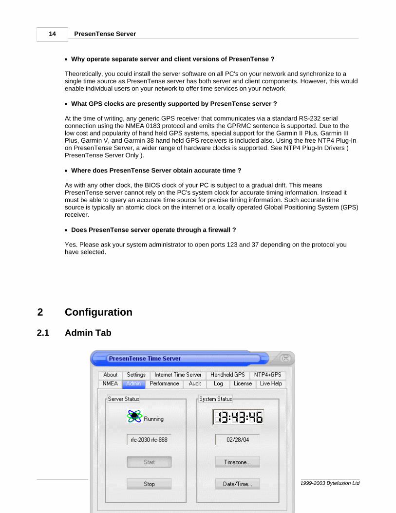
2.1 Admin Tab

Configuration 15
© 1999-2003 Bytefusion Ltd
· Service Status
This panel indicates if PresenTense is running or stopped. Use the buttons to start and/or stop theservice.
· System Status
This panel indicates the system time in 24-hour format. Use the buttons to conveniently access othercontrol paneldate/time functions.
NOTE : Making configuration changes through the control panel applet requires administratorprivileges.
2.2 Settings Tab
· Reference Time Source
This option allows you to specify how PresenTense Server obtains accurate time. Possible optionsare :
a) Internet Time Server : Obtain accurate time from another time server on your local area networkor the public internet from servers supporting common time protocols. Selecting this option willenable the Internet Time Server tab .

PresenTense Server16
© 1999-2003 Bytefusion Ltd
b) Handheld GPS (Basic) : Obtain accurate time from a Global Positioning System receiver. Supportis included for GPS units featuring the NMEA 0183 protocol data via an RS-232 link (serial port) andemits the GPRMC sentence. Special algorithms permit obtaining accurate time from low cost, handheld GPS receivers. Selecting this option will enable the Handheld GPS tab and the NMEA tab.
c) Local System Clock : Assume that the local system clock reflects accurate time. Most computerclocks are subject to a drift and thus do not remain synchronized to accurate time. However, someGPS clocks provide their own software to synchronize the local system to their GPS hardware. If youhave one of these units and wish to use PresenTense server to distribute time to clients on yournetwork, use the Local BIOS clock option.
d) NTP4 Time Server + GPS : Use free NTP4 plug-in DLL. The NTP4 plug-in is shipped with both theevaluation and the retail edition of PresenTense Server and supports common GPS receivers andNTP network time servers. See NTP4 Plug-In.
· Alarm Notification
If you wish to be notified via email if PresenTense Server is unable to contact the time source,specify your email address and the mail server PresenTense should use for sending of messages. Atthis time, only the SMTP (Simple Mail Transfer Protocol) is supported. Check the Lotus box if youare running a Lotus Domino mail server. This feature enables a Lotus Domino work-around.
· Event Logging
Use this option to enable/disable event logging the Windows NT application event log and to specifywhat message types qualify for logging
· Maximum Clock Correction
This option limits the number of seconds by which PresenTense Server will adjust its own systemclock. This prevents serious time server errors from propagating across the network. It isrecommended to override this option for initial clock adjustment to allow PresenTense to makeadjustments as necessary on system startup.
NOTE : Making configuration changes through the control panel applet requires administratorprivileges.
2.3 Internet Time Server Tab

Configuration 17
© 1999-2003 Bytefusion Ltd
· Reference Time Server
This option allows you to specify one primary and one redundant time server from whichPresenTense Server derives its own time. You may specify either an IP address, hostname, or DNSname. If you elect to specify a hostnameor DNS name, please ensure that name resolution is properly configured on your TCP/IP network.
Automatic fail-over from the primary to the redundant time source occurs if the name for the primarysource cannot be resolved, or PresenTense Server times out waiting for a reply from the primary timesource.
If you decide to synchronize to a time server on the internet rather than a corporate time server,ensure also that firewall rules permit the network traffic for the protocol you select.
· Time Source Type
This option allows you to specify the type of time source you wish to use. Your choice here dependsmainly on the availability of services offered and your time keeping requirements. The recommendedand by far most accurate option is NTP/SNTP.
· Synchronize Every
This option allows you to set the polling interval. How often PresenTense Server needs to poll its timesource depends primarily on the clock drift of the local BIOS clock and your time keepingrequirements. The default value is 15 minutes.
· Timeout
This option determines how long PresenTense Server waits for a reply from its time source. Thisvalue should not exceed the polling interval.
· Maximum NTP Root Dispersion
This option can be used to validate time stamps received from NTP time sources. Use it to rejecttime stamps which exceed a certain nominal error.
2.4 Handheld GPS Tab

PresenTense Server18
© 1999-2003 Bytefusion Ltd
· Model
Use this option to specify the model of your GPS receiver. Supported unitsat this time are:
a) Generic : Support for generic NMEA GPS receivers that conform to the NMEA 0183 standard andemit the GPRMC or GPGGA sentence at regular, precise intervals of one or two seconds.b) Garmin 38 : Hand held GPS receiver from Garmin Corporation.c) Garmin II Plus : Hand held GPS receiver from Garmin Corporation with support for externalantenna connection. This option includes the Garmin III Plus and the Garmin V.d) TripNav TN-200 : USB port powered GPS receiver from Rayming Corporation. Please note thatlong USB cables and operating system overheads in servicing the virtual COM port may result insignal offsets that are specific to your site. If you require a high degree of accuracy, we recommendthe use of the NTP4 plugin TripNav TN-200 driver and suggest you calibrate your GPS installation asillustrated in the section NTP4 Plug-In Driver Calibration.
· Serial Port
Use this option to specify the serial port on your PC to which the GPS receiver is connected.
· Speed
At present, NMEA 0183 only supports 4800 Baud.
Trademarks
Microsoft Windows and Windows NT are either registered trademarks or trademarks of MicrosoftCorporation. No associations are implied.
2.5 NTP4+GPS Tab
Starting with version 3.5, PresenTense Server includes a plug-in which supports NTP version 3 & 4according to RFC 1305. This plug-in is distributed with PresenTense Server free of charge. If yourequire the newest, industry standard version of NTP, the use of the NTP version 4 plug-in isrecommended. To obtain the latest version of our NTP4 plug-in for PresenTense Server free of chargeat any time, kindly email us at [email protected].
PresenTense Server generates the configuration file NTP.CONF for the NTP4 plug-In automaticallyfrom the settings you specify or you can edit this configuration file directly. The latter is onlyrecommended for advanced users. Please refer to the parameter list shown below for a detailedexplanation of each parameter / setting.

Configuration 19
© 1999-2003 Bytefusion Ltd
· Accurate time Source
This option allows you to specify one primary and two redundant time servers from which the NTP4plug-in derives its own time. You may specify either an IP address, hostname, or DNS name for eachserver. If you elect to specify a hostname or DNS name, please ensure that name resolution isproperly configured on your TCP/IP network. If you decide to synchronize to a time server on theinternet rather than a corporate time server, ensure also that firewall rules permit the network trafficfor the protocol you select. Time servers specified here should support version 3 or 4 of the NTPprotocol. Click the key icon to select an encryption key to be used to authenticate each server if yourequire secure NTP. Authentication uses the MD5 secure hash algorithm. See alsoNTP4 Key Generator.
· NTP Version
This option allows you to specify the version number to be used for outgoing NTP packets. Possiblevalues are version 3 and version 4. Regardless of the value chosen here, the NTP plug-in willservice clients of both version 3 and 4 when it itself is queried by other NTP hosts.
· NTP Port
This option allows you to specify an alternate NTP port. By convention, the NTP protocol operates onport 123 and in all but the most extraordinary circumstances you will want to use port 123 in order toretain compatibility with other NTP systems. Some circumstances, however, warrant changing thedefault NTP port. If you operate PresenTense Server on a local area network behind a firewall whichblocks incoming traffic to privileged ports (<1024) and are unable or not permitted to reconfigure yourfirewall to suit, you might wish to reconfigure the NTP4 plug-in to operate on an alternate port. Be
PresenTense Server20
© 1999-2003 Bytefusion Ltd
advised that you will need to adjust any time client software to use the new port settings also.
· Minimum Poll Interval
This option allows you to specify the minimum poll interval for NTP messages. Typically the NTP4plug-in will poll time servers at the rate specified as the minimum poll interval until the algorithm hasachieved synchronization of the local system with its accurate time source(s).
· Maximum Poll Interval
This option allows you to specify the maximum poll interval for NTP messages. After synchronizationwith its accurate time source(s) has been achieved, the NTP4 Plug-In may grow the interval betweenqueries to its accurate time source(s) up to the maximum poll interval or as required to maintainsynchronization.
· Use Burst Mode
This option tells the NTP4 plug-in to use eight packets instead of the usual one packet when polling atime server. When enabled, this option considerably increases timekeeping accuracy.
· Use Hardware Clock
This option allows you to switch to NTP4 reference clock support. Use this option if instead ofobtaining accurate time over the network from another time server, you wish to obtain accurate timefrom a hardware device attached to the serial port ( RS-232 interface) of your computer, such as aradio clock or GPS clock. Please note that this functionality duplicates some of PresenTenseServer's built-in capabilities. For example, PresenTense Server has native support for NMEA enabledGPS clocks - the NMEA driver in the NTP4 plug-in duplicates this functionality. You are free to chosewhichever you prefer.

Configuration 21
© 1999-2003 Bytefusion Ltd
· Clock Model
Use this option to specify the make and model of your hardware clock. Supported options alsoinclude "Undisciplined local clock" and "Generic NMEA GPS receiver". The "Undisciplined localclock" option advises the NTP4 plug-in to trust the time on your computer as accurate time - usefulwhen clocks provide native software to synchronize the local system. The "Generic NMEA GPSreceiver" option is useful if your GPS system or radio clock is not specifically listed here but supportsthe NMEA protocol. Note that the "Undisciplined local clock" option corresponds to PresenTenseServer's native "Local BIOS clock" option on the settings tab. Equally, the "Generic NMEA GPSreceiver" NTP4 plug-in option corresponds to PresenTense Server's native "Generic" NMEA supportoption on the GPS tab. Please refer to NTP4 Plug-In Drivers for a comprehensive list of hardwaredevices supported by the NTP4 plug-in.
· Serial Port
Use this option to specify the serial port on your PC to which the GPS or radio clock receiver isconnected. Supported options are COM1 through COM4.
· Speed
Use this option to specify the Baud rate of your GPS or radio clock. Supported options are 1200Baud, 2400 Baud, 4800 Baud and 9600 Baud.
· Driver Tunables
Use this option to specify additional parameters to be passed directly to the hardware clock driver

PresenTense Server22
© 1999-2003 Bytefusion Ltd
specified under "Clock Model". This option is recommended for advanced users only.
· Let me edit ntp.conf directly
This option allows you to switch to direct edit mode. In direct edit mode, you are free to compose yourown NTP.CONF file. This option is recommended for advanced users only.
2.6 NMEA Tab

Configuration 23
© 1999-2003 Bytefusion Ltd
This window will capture NMEA output from your GPS receiver. Use it to verify connectivity to yourGPS as well as COM port and Baud settings. If you cannot see any output from your GPS in thiswindow, PresenTense Server will not be able to synchronize to your GPS.
2.7 Performance Tab
The Priority Boost setting allows you to increase the real-time priority of PresenTense in the context ofthe Microsoft Windows operating system. Tasks with a higher priority receive a greater share of CPUattention. If your system runs many CPU intensive applications, use the "Priority Class High" setting toenhance the accuracy of PresenTense Server.
Trademarks
Microsoft Windows is a registered trademark of Microsoft Corporation.

PresenTense Server24
© 1999-2003 Bytefusion Ltd
2.8 Log Tab
The Log tab gives you access to the operating system event log and always displays the last tenentries PresenTense Server has committed to the system event log. You need to have logging enabledon the Settings tab in order for this feature to work. The log tab entries are refreshed from the operatingsystem event log whenever you switch to the log tab from any of the other tabs or when the Refreshbutton is clicked.
2.9 NTP4 Key Generator
The NTP4 key generator, ntp-genkeys, creates encryption keys for your server. These keys may beused by PresenTense client software to authenticate your server's identity. The keys are maintained inthe file NTP.KEYS in the PresenTense Server application folder. You will need to distribute this filesecurely to workstations running PresenTense client and install the file in the PresenTense applicationfolder. Newly generated keys will be read as soon the PresenTense server or PresenTense clientservice is restarted. ntp-genkeys is a companion program of the NTP4 Plug-In. The newest version ofntp-genkeys may be obtained free of charge by writing to [email protected].

Configuration 25
© 1999-2003 Bytefusion Ltd
2.10 NTP4 Plug-In Drivers
Besides synchronizing to other NTP servers via a local area or wide area network, the NTP4 plug-inalso allows you to synchronize your computer to a number of hardware clocks, includingGPS satellite receivers and radio clocks. A number of physics laboratories in various countries operatelow frequency radio transmitters with ranges spanning continents. These include :
· WWV / WWVB, National Institute of Standards and Technology, Ft. Collins, Colorado, USA. Thesignal transmitted from Ft. Collins can be received throughout most of the continental United Statesas well as throughout most of Canada.
· DCF77, National Institute of Natural and Engineering Sciences, Germany. The DCF77 signal canbe received throughout most of western Europe, the British Isles, and is reported to be received atnight as far as India, Israel and Yemen.
· JJY, Communication Research Laboratory (CRL), Japan. CRL broadcasts Japan Standard Timevia long wave radio.
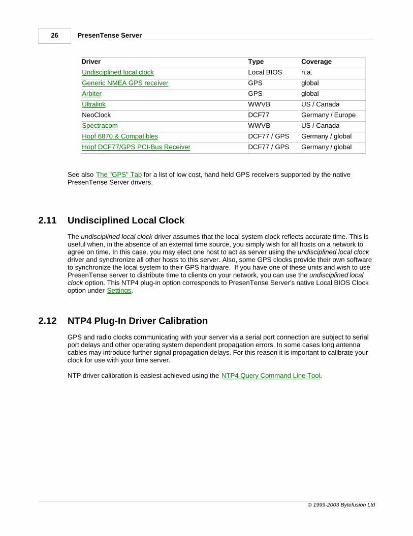
The PresenTense NTP4 plug-in contains drivers for these and more.A comprehensive list of drivers supported by the NTP4 plug-in is shown in the table below.
PresenTense Server26
© 1999-2003 Bytefusion Ltd
Driver Type Coverage
Undisciplined local clock Local BIOS n.a.
Generic NMEA GPS receiver GPS global
Arbiter GPS global
Ultralink WWVB US / Canada
NeoClock DCF77 Germany / Europe
Spectracom WWVB US / Canada
Hopf 6870 & Compatibles DCF77 / GPS Germany / global
Hopf DCF77/GPS PCI-Bus Receiver DCF77 / GPS Germany / global
See also The "GPS" Tab for a list of low cost, hand held GPS receivers supported by the nativePresenTense Server drivers.
2.11 Undisciplined Local Clock
The undisciplined local clock driver assumes that the local system clock reflects accurate time. This isuseful when, in the absence of an external time source, you simply wish for all hosts on a network toagree on time. In this case, you may elect one host to act as server using the undisciplined local clockdriver and synchronize all other hosts to this server. Also, some GPS clocks provide their own softwareto synchronize the local system to their GPS hardware. If you have one of these units and wish to usePresenTense server to distribute time to clients on your network, you can use the undisciplined localclock option. This NTP4 plug-in option corresponds to PresenTense Server's native Local BIOS Clockoption under Settings.
2.12 NTP4 Plug-In Driver Calibration
GPS and radio clocks communicating with your server via a serial port connection are subject to serialport delays and other operating system dependent propagation errors. In some cases long antennacables may introduce further signal propagation delays. For this reason it is important to calibrate yourclock for use with your time server.
NTP driver calibration is easiest achieved using the NTP4 Query Command Line Tool.

Configuration 27
© 1999-2003 Bytefusion Ltd
The screenshot above shows a test system running a Spectracom 8189 clock as primary time sourceand a local area network NTP server 192.168.1.19 as secondary time source. Two public NTP serverson the internet facilitate external verification of test results. The two servers on the internet are subjectto round trip delays on the order of 300ms as well as substantial network jitter and therefore exhibitgreater offsets with respect to the local system clock than the local area network NTP server.
You can use the time1 driver parameter to compensate for signal delays and other propagation errors.The example shown above illustrates how to compensate for a nominal 6 millisecond error. The finalscreenshot shown below shows both time sources in agreement to within 2.5 milliseconds. Dependingon your requirements you might wish to calibrate to within closer specifications.

PresenTense Server28
© 1999-2003 Bytefusion Ltd
2.13 NTP4 Plug-In Driver Troubleshooting
If your GPS or radio clock is listed as supported or you have a clock model which you feel is compatiblewith a clock listed under NTP4 Plug-In Drivers and your clock is unable to communicate withPresenTense Server, kindly let us know. Please submit a detailed problem report by email [email protected] listing details of both the operating system and service pack information ofyour computer as well as the exact model number and description of your GPS or radio clock.
Additionally, we request that you submit a serial port capture, showing the interaction betweenPresenTense Server and your clock. This will confirm to us that your PC hardware is operating correctlyand that your GPS or radio clock is properly connected to your PC. The serial port capture will also helpus troubleshoot the interaction between your clock and PresenTense Server. We request that yousubmit your serial port capture as a ".lgs" file as produced by the HHD Serial Port Monitor. The HHDSerial Port Monitor is shareware and available for download from HHD Software. A sample serial portcapture showing the interaction between PresenTense server and an Arbiter GPS receiver is displayedbelow.

Configuration 29
© 1999-2003 Bytefusion Ltd
3 Hardware
3.1 TripNav TN-200
With PresenTense Server and the TripNav TN-200 you can build your own network enabled, low cost,GPS master clock to synchronize all your computers to atomic time via the global positioning satellitesystem. The TripNav TN-200 is easy to use and requires only a standard USB port, no external powerand features a water resistant housing for installation inside or outside of buildings. Simply add any off-the-shelf USB extension cable to suit your own antenna cable length requirements.
The TripNav TN-200 features a built in 12 channel GPS antenna, is WAAS capable for enhancedprecision, and achieves an accuracy of 1 microsecond to UTC. Find out more about the TripNav TN-200 at Rayming Corporation's home page www.rayming.com.
Installation Notes : The TripNav TN-200 software installs a virtual COM port, typically on COM 5, whichrelays the NMEA output from the TN-200 GPS unit to PresenTense Server. Please note that long USBcables and operating system overheads in servicing the virtual COM port may result in signal offsetsthat are specific to your site. You may need to calibrate your GPS installation via the offset calibrationfactor as illustrated in the section NTP4 Plug-In Driver Calibration. See also PresenTense NTP Auditor
PresenTense Server30
© 1999-2003 Bytefusion Ltd
for additional information on NTP calibration.
Driver tunables :
Tunable Values/Units Description
time1 seconds offset calibration factor
stratum 0-15 server stratum, default 0
refid one to four letters server identifier, defaultGPS
Note: TripNav TN-200 specifications are subject to change. Please visit Rayming Corporation for moreinformation.
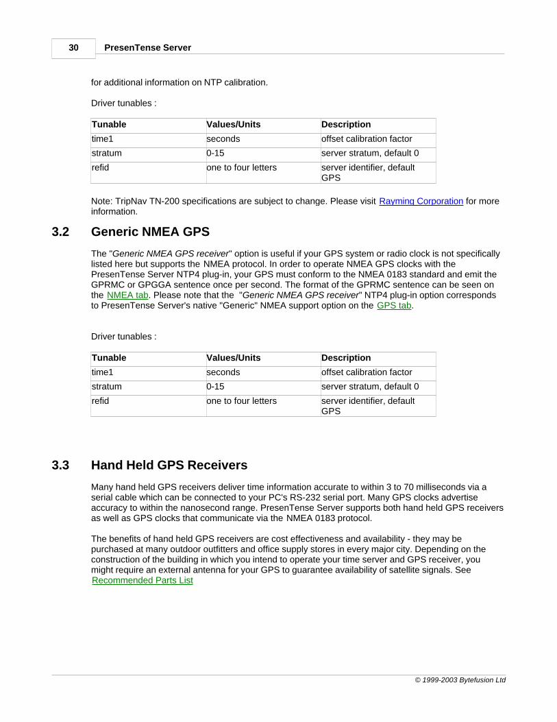
3.2 Generic NMEA GPS
The "Generic NMEA GPS receiver" option is useful if your GPS system or radio clock is not specificallylisted here but supports the NMEA protocol. In order to operate NMEA GPS clocks with thePresenTense Server NTP4 plug-in, your GPS must conform to the NMEA 0183 standard and emit theGPRMC or GPGGA sentence once per second. The format of the GPRMC sentence can be seen onthe NMEA tab. Please note that the "Generic NMEA GPS receiver" NTP4 plug-in option correspondsto PresenTense Server's native "Generic" NMEA support option on the GPS tab.
Driver tunables :
Tunable Values/Units Description
time1 seconds offset calibration factor
stratum 0-15 server stratum, default 0
refid one to four letters server identifier, defaultGPS
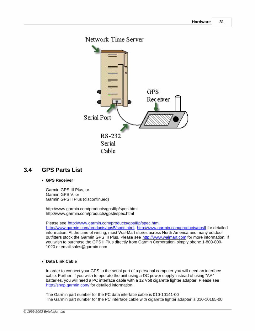
3.3 Hand Held GPS Receivers
Many hand held GPS receivers deliver time information accurate to within 3 to 70 milliseconds via aserial cable which can be connected to your PC's RS-232 serial port. Many GPS clocks advertiseaccuracy to within the nanosecond range. PresenTense Server supports both hand held GPS receiversas well as GPS clocks that communicate via the NMEA 0183 protocol.
The benefits of hand held GPS receivers are cost effectiveness and availability - they may bepurchased at many outdoor outfitters and office supply stores in every major city. Depending on theconstruction of the building in which you intend to operate your time server and GPS receiver, youmight require an external antenna for your GPS to guarantee availability of satellite signals. SeeRecommended Parts List
Hardware 31
© 1999-2003 Bytefusion Ltd
3.4 GPS Parts List
· GPS Receiver
Garmin GPS III Plus, orGarmin GPS V, orGarmin GPS II Plus (discontinued)
http://www.garmin.com/products/gpsIIIp/spec.htmlhttp://www.garmin.com/products/gps5/spec.html
Please see http://www.garmin.com/products/gpsIIIp/spec.html,http://www.garmin.com/products/gps5/spec.html, http://www.garmin.com/products/gpsII for detailedinformation. At the time of writing, most Wal-Mart stores across North America and many outdooroutfitters stock the Garmin GPS III Plus. Please see http://www.walmart.com for more information. Ifyou wish to purchase the GPS II Plus directly from Garmin Corporation, simply phone 1-800-800-1020 or email [email protected].
· Data Link Cable
In order to connect your GPS to the serial port of a personal computer you will need an interfacecable. Further, if you wish to operate the unit using a DC power supply instead of using "AA"batteries, you will need a PC interface cable with a 12 Volt cigarette lighter adapter. Please seehttp://shop.garmin.com/ for detailed information.
The Garmin part number for the PC data interface cable is 010-10141-00The Garmin part number for the PC interface cable with cigarette lighter adapter is 010-10165-00.

PresenTense Server32
© 1999-2003 Bytefusion Ltd
You may also visit http://www.globalmart.com/gps/garmin/accessories/acc2/cables/ or visithttp://www.globe-mart.com/ and search for "Garmin PC Interface Cable Cigarette Lighter Adapter".
· External Antenna
Your GPS needs to have an unobstructed view of the sky in order to receive satellite signals. Theroofs of wooden buildings sometimes allow the satellite signal to pass through. In some cases, simplyplacing the GPS receiver near a window will result in adequate signal strength. In all other cases, anexternal antenna most be mounted outdoors with a clear view towards the sky and connected to yourGPS receiver. We recommend the external antennas GA-29 ( Garmin part number 010-00174-00 ) orGA-26C ( Garmin part number 010-10052-04). Please see http://shop.garmin.com/ for detailedinformation.
3.5 Arbiter
Arbiter sells a range of global positioning system satellite clock receivers. This driver supports model1084, model 1088, model 1092 and model 1093. To operate these units with the PresenTense ServerNTP4 plug-in, turn off the daylight savings time feature using the D0 command and turn on initiate UTCbroadcasts using the BU command. The NTP4 plug-in initiates communication with the clock bysending a time quality query ( TQ ). Once an echo reply including the time quality character has beenreceived from the clock, the NTP4 plug-in turns on pulse per second timestamps by sending a B5command to the clock. The Arbiter clock in turn responds by broadcasting a "format b5" time indicationonce every second.
Arbiter 1088 Satellite Controlled Clock
Arbiter 1084 A,B, & C Satellite Controlled Clocks

Hardware 33
© 1999-2003 Bytefusion Ltd
Arbiter 1092 A,B, & C Satellite Controlled Clocks
Arbiter 1093 A,B, & C Satellite Controlled Clocks
Images reproduced with permission from Arbiter Systems Inc.
Driver tunables :

PresenTense Server34
© 1999-2003 Bytefusion Ltd
Tunable Values/Units Description
time1 seconds offset calibration factor
stratum 0-15 server stratum, default 0
refid one to four letters server identifier, defaultGPS
3.6 Spectracom Clock Formats
Spectracom Netclocks support a variety of data formats. The NTP4 Plug-In Driversupports format zero and format three. The screenshots below show the real-timeinteraction between PresenTense Server and a Spectracom Netclock using dataformat zero and data format three. This data is provided for reference andtroubleshooting purposes only. See NTP4 Plug-In Driver Calibration and NTP4 Plug-In Driver Troubleshooting for more information.
· Data Format Zero

Hardware 35
© 1999-2003 Bytefusion Ltd
· Data Format Three
3.7 Spectracom
Spectracom manufactures both GPS and radio clock receivers. This driver supports the followingSpectracom clock models : 8182 (WWVB), 8183 (GPS), 8183A (GPS), 8183ES (GPS) and 8189(GPS). The driver requires the Spectracom clock to be configured to employ data format 2 using 24hour time, no automatic daylight savings time correction, and 9600 bps. Some Spectracom clockmodels feature DIP switches - other models are configured via a dedicated telnet or serial portconnection.
Spectracom 8189

PresenTense Server36
© 1999-2003 Bytefusion Ltd
Spectracom 8182
Spectracom 8283
Images reproduced with permission from Spectracom Corporation.
Configuration:
Connect a serial cable from your computer to the RS-232 setup port on the Spectracom 8189 and opena HyperTerminal session using the following parameters : 9600 bits per second, 8 data bits, no parityand flow control Xon / Xoff. This will allow you to configure the operation of your Spectracom clock.Type "sm on" and hit enter to enter setup mode for the serial interface. Then type "ser1 9600 00 T -

Hardware 37
© 1999-2003 Bytefusion Ltd
00.00 0" and hit enter to configure the clock to respond to the polling character "T" using 9600 bits persecond. Close the HyperTerminal session, saving the operating parameters for your Spectracom clock.
You should now be able to verify operation of your clock by disconnecting the serial cable from the RS-232 setup port and connecting it to the RS-232 communication (COM) port. Re-open yourHyperTerminal session and repeatedly hit capital "T" on your keyboard. This should prompt the clock toreply with one time stamp for each key press as shown below. Close your HyperTerminal session.
When your Spectracom clock is synchronized to satellites in geostationary orbit, the time sync LED onthe front panel will change color from red to green as shown below. You are now ready to startsynchronizing your computer to your satellite clock using PresenTense Server.

PresenTense Server38
© 1999-2003 Bytefusion Ltd
Driver tunables :
Tunable Values/Units Description
time1 seconds offset calibration factor
stratum 0-15 server stratum, default 0
refid one to four letters server identifier, defaultWWVB
3.8 Hopf DCF77/GPS PCI-Bus Receiver
Hopf Elektronik manufactures GPS satellite clocks as well as radio clocks designed for the DCF77 timesignal broadcast by the National Institute of Natural and Engineering Sciences in Germany. This driversupports the Hopf Elektronik clock model 6039 PCI board. Both, the DCF and GPS variants aresupported. You may visit Hopf Elektronik on the web at http://www.hopf-time.com , or email technicalsupport at [email protected].
Hopf 6039 PCI-Bus Receiver
Hopf 6039 Operation
When the unit is slotted into an internal PCI bus of a personal computer and connected to its external

Hardware 39
© 1999-2003 Bytefusion Ltd
GPS antenna, the Hopf 6039 diagnostic software will display the synchronization status of the unit onthe Date & Time tab in the Status field. Satellite signal strength is displayed on the Satellites tab.When the Hopf 6039 clock has successfully synchronized to satellite time or DCF77 time, the statusindication changes to "clock is radio synchronous with crystal control standard time" as shownbelow. If you wish PresenTense Server to use the timestamps obtained from your Hopf clock prior tothis stage, see "flag1" under Driver Tunables at the bottom of this page.
Hopf 6039 Benchmark Tests
The Hopf 6039 PCI bus board has performed extremely well in benchmark tests with sub-millisecondaccuracy.

PresenTense Server40
© 1999-2003 Bytefusion Ltd
Driver tunables :
Tunable Values/Units Description
time1 seconds offset calibration factor
refid one to four letters server identifier, defaultGPS or DCF
flag1 0 or 1 Use value 1 to forcesynchronization when only"crystal driven".
3.9 Hopf 6870 & Compatibles
Hopf Elektronik manufactures GPS satellite clocks as well as radio clocks designed for the DCF77 timesignal broadcast by the National Institute of Natural and Engineering Sciences in Germany. This driversupports the Hopf Elektronik clock model 6870 and compatible clocks. These rack mount units aredesigned to connect to a time server on a personal computer via the RS-232 serial port interface. Youmay visit Hopf Elektronik on the web at http://www.hopf-time.com , or email technical support [email protected].
Hopf 6870
Hopf 6870 Operation
When the unit is connected to a personal computer via the RS-232 interface and connected to itsexternal GPS antenna, the Hopf 6870 diagnostic software will display the synchronization status of theunit on the Date & Time tab in the Status field. Satellite signal strength is displayed on the Satellitestab. When the Hopf 6870 clock has successfully synchronized to satellite time or DCF77 time the statusindication changes to "clock is radio synchronous with crystal control standard time". If you wishPresenTense Server to use the timestamps obtained from the Hopf clock prior to this stage, see "flag1"under Driver Tunables at the bottom of this page.

Hardware 41
© 1999-2003 Bytefusion Ltd

PresenTense Server42
© 1999-2003 Bytefusion Ltd
Driver tunables :
Tunable Values/Units Description
time1 seconds offset calibration factor
refid one to four letters server identifier, defaultGPS or DCF
flag1 0 or 1 Use value 1 to forcesynchronization when only"crystal driven".
3.10 Ultralink
Ultralink manufactures precision radio time receivers. Ultralink clocks use the WWVB signal broadcastby the National Institute of Standards and Technology, Ft. Collins, Colorado, USA. The signaltransmitted from Ft. Collins can be received throughout most of the continental United States as well asthroughout most of Canada. This driver supports Ultralink clock models 320, 330, 331 and 332.
Driver tunables :

Hardware 43
© 1999-2003 Bytefusion Ltd
Tunable Values/Units Description
flag1 0 or 1 Use 1 for model 320. Don'tset this flag if DIP switch 2is set on model 33x seriesclocks.
4 RFC 868
4.1 RFC 868
Network Working GroupRequest for Comments: 868
J. Postel - ISIK. Harrenstien - SRIMay 1983
Time Protocol
This RFC specifies a standard for the ARPA Internet community. Hosts on the ARPA Internet thatchoose to implement a Time Protocol are expected to adopt and implement this standard.
This protocol provides a site-independent, machine readable date and time. The Time service sendsback to the originating source the time in seconds since midnight on January first 1900.
One motivation arises from the fact that not all systems have a date/time clock, and all are subject tooccasional human or machine error. The use of time-servers makes it possible to quickly confirm orcorrect a system's idea of the time, by making a brief poll of several independent sites on the network.
This protocol may be used either above the Transmission Control Protocol (TCP) or above the UserDatagram Protocol (UDP).
When used via TCP the time service works as follows:
S: Listen on port 37 (45 octal).
U: Connect to port 37.
S: Send the time as a 32 bit binary number.
U: Receive the time.
U: Close the connection.
S: Close the connection.
The server listens for a connection on port 37. When the connection is established, the server returnsa 32-bit time value and closes the connection. If the server is unable to determine the time at its site, itshould either refuse the connection or close it without sending anything.
PresenTense Server44
© 1999-2003 Bytefusion Ltd
When used via UDP the time service works as follows:
S: Listen on port 37 (45 octal).
U: Send an empty datagram to port 37.
S: Receive the empty datagram.
S: Send a datagram containing the time as a 32 bit binary number.
U: Receive the time datagram.
The server listens for a datagram on port 37. When a datagram arrives, the server returns a datagramcontaining the 32-bit time value. If the server is unable to determine the time at its site, it shoulddiscard the arriving datagram and make no reply.
The Time
The time is the number of seconds since 00:00 (midnight) 1 January 1900 GMT, such that the time 1 is12:00:01 am on 1 January 1900 GMT; this base will serve until the year 2036.
For example:
the time 2,208,988,800 corresponds to 00:00 1 Jan 1970 GMT,
2,398,291,200 corresponds to 00:00 1 Jan 1976 GMT,
2,524,521,600 corresponds to 00:00 1 Jan 1980 GMT,
2,629,584,000 corresponds to 00:00 1 May 1983 GMT,
and -1,297,728,000 corresponds to 00:00 17 Nov 1858 GMT.
5 RFC 2030
5.1 RFC 2030
Network Working GroupRequest for Comments: 2030Obsoletes: 1769Category: Informational
D. MillsUniversity of DelawareOctober 1996
Simple Network Time Protocol (SNTP) Version 4

RFC 2030 45
© 1999-2003 Bytefusion Ltd
for IPv4, IPv6 and OSI
Status of this Memo
This memo provides information for the Internet community. This memo does not specify an Internetstandard of any kind. Distribution of this memo is unlimited.
Abstract
This memorandum describes the Simple Network Time Protocol (SNTP) Version 4, which is anadaptation of the Network Time Protocol (NTP) used to synchronize computer clocks in the Internet.SNTP can be used when the ultimate performance of the full NTP implementation described in RFC-1305 is not needed or justified. When operating with current and previous NTP and SNTP versions,SNTP Version 4 involves no changes to the NTP specification or known implementations, but rather aclarification of certain design features of NTP which allow operation in a simple, stateless remote-procedure call (RPC) mode with accuracy and reliability expectations similar to the UDP/TIME protocoldescribed in RFC-868.
The only significant protocol change in SNTP Version 4 over previous versions of NTP and SNTP is amodified header interpretation to accommodate Internet Protocol Version 6 (IPv6) [DEE96] and OSI[COL94] addressing. However, SNTP Version 4 includes certain optional extensions to the basicVersion 3 model, including an anycast mode and an authentication scheme designed specifically formulticast and anycast modes. While the anycast mode extension is described in this document, theauthentication scheme extension will be described in another document to be published later. Until suchtime that a definitive specification is published, these extensions should be considered provisional.
This memorandum obsoletes RFC-1769, which describes SNTP Version 3. Its purpose is to correctcertain inconsistencies in the previous document and to clarify header formats and protocol operationsfor current NTP Version 3 (IPv4) and proposed NTP Version 4 (IPv6 and OSI), which are also used forSNTP. A working knowledge of the NTP Version 3 specification RFC-1305 is not required for animplementation of SNTP.
1. Introduction
The Network Time Protocol (NTP) Version 3 specified in RFC-1305 [MIL92] is widely used tosynchronize computer clocks in the global Internet. It provides comprehensive mechanisms to accessnational time and frequency dissemination services, organize the time-synchronization subnet andadjust the local clock in each participating subnet peer. In most places of the Internet of today, NTPprovides accuracies of 1-50 ms, depending on the characteristics of the synchronization source andnetwork paths.
RFC-1305 specifies the NTP Version 3 protocol machine in terms of events, states, transition functionsand actions and, in addition, engineered algorithms to improve the timekeeping quality and mitigateamong several synchronization sources, some of which may be faulty. To achieve accuracies in the lowmilliseconds over paths spanning major portions of the Internet of today, these intricate algorithms, ortheir functional equivalents, are necessary. However, in many cases accuracies in the order ofsignificant fractions of a second are acceptable. In such cases, simpler protocols such as the TimeProtocol [POS83], have been used for this purpose. These protocols usually involve an RPC exchangewhere the client requests the time of day and the server returns it in seconds past some knownreference epoch.
NTP is designed for use by clients and servers with a wide range of capabilities and over a wide rangeof network delays and jitter characteristics. Most users of the Internet NTP synchronization subnet oftoday use a software package including the full suite of NTP options and algorithms, which are relativelycomplex, real-time applications (see http://www.eecis.udel.edu/~ntp). While the software has been

PresenTense Server46
© 1999-2003 Bytefusion Ltd
ported to a wide variety of hardware platforms ranging from personal computers to supercomputers,its sheer size and complexity is not appropriate for many applications. Accordingly, it is useful to explorealternative access strategies using simpler software appropriate for less stringent accuracyexpectations.
This document describes the Simple Network Time Protocol (SNTP) Version 4, which is a simplifiedaccess strategy for servers and clients using NTP Version 3 as now specified and deployed in theInternet, as well as NTP Version 4 now under development. The access paradigm is identical to theUDP/TIME Protocol and, in fact, it should be easily possible to adapt a UDP/TIME clientimplementation, say for a personal computer, to operate using SNTP. Moreover, SNTP is alsodesigned to operate in a dedicated server configuration including an integrated radio clock. With carefuldesign and control of the various latencies in the system, which is practical in a dedicated design, it ispossible to deliver time accurate to the order of microseconds.
SNTP Version 4 is designed to coexist with existing NTP and SNTP Version 3 clients and servers, aswell as proposed Version 4 clients and servers. When operating with current and previous versions ofNTP and SNTP, SNTP Version 4 requires no changes to the protocol or implementations now runningor likely to be implemented specifically for NTP in SNTP Version 4. To a NTP or SNTP server, NTP andSNTP clients are undistinguishable; to a NTP or SNTP client, NTP and SNTP servers areundistinguishable. Like NTP servers operating in non-symmetric modes, SNTP servers are statelessand can support large numbers of clients; however, unlike most NTP clients, SNTP clients normallyoperate with only a single server. NTP and SNTP Version 3 servers can operate in unicast andmulticast modes. In addition, SNTP Version 4 clients and servers can implement extensions to operatein anycast mode.
It is strongly recommended that SNTP be used only at the extremities of the synchronization subnet.SNTP clients should operate only at the leaves (highest stratum) of the subnet and in configurationswhere no NTP or SNTP client is dependent on another SNTP client for synchronization. SNTP serversshould operate only at the root (stratum 1) of the subnet and then only in configurations where no othersource of synchronization other than a reliable radio or modem time service is available. The full degreeof reliability ordinarily expected of primary servers is possible only using the redundant sources, diversesubnet paths and crafted algorithms of a full NTP implementation. This extends to the primary source ofsynchronization itself in the form of multiple radio or modem sources and backup paths to other primaryservers should all sources fail or the majority deliver incorrect time. Therefore, the use of SNTP ratherthan NTP in primary servers should be carefully considered.
An important provision in this document is the reinterpretation of certain NTP Version 4 header fieldswhich provide for IPv6 and OSI addressing and optional anycast extensions designed specifically formulticast service. These additions are in conjunction with the proposed NTP Version 4 specification,which will appear as a separate document. The only difference between the current NTP Version 3 andproposed NTP Version 4 header formats is the interpretation of the four-octet Reference Identifier field,which is used primarily to detect and avoid synchronization loops. In Version 3 and Version 4 primary(stratum-1) servers, this field contains the four-character ASCII reference identifier defined later in thisdocument. In Version 3 secondary servers and clients, it contains the 32-bit IPv4 address of thesynchronization source. In Version 4 secondary servers and clients, it contains the low order 32 bits ofthe last transmit timestamp received from the synchronization source.
In the case of OSI, the Connectionless Transport Service (CLTS) is used [ISO86]. Each SNTP packetis transmitted as the TS-Userdata parameter of a T-UNITDATA Request primitive. Alternately, theheader can be encapsulated in a TPDU which itself is transported using UDP [DOB91]. It is not advisedthat NTP be operated at the upper layers of the OSI stack, such as might be inferred from [FUR94], asthis could seriously degrade accuracy. With the header formats defined in this document, it is inprinciple possible to interwork between servers and clients of one protocol family and another, althoughthe practical difficulties may make this inadvisable.
In the following, indented paragraphs such as this one contain information not required by the formal

RFC 2030 47
© 1999-2003 Bytefusion Ltd
protocol specification, but considered good practice in protocol implementations.
2. Operating Modes and Addressing
SNTP Version 4 can operate in either unicast (point to point), multicast (point to multipoint) or anycast(multipoint to point) modes. A unicast client sends a request to a designated server at its unicastaddress and expects a reply from which it can determine the time and, optionally, the roundtrip delayand local clock offset relative to the server. A multicast server periodically sends a unsolicited messageto a designated IPv4 or IPv6 local broadcast address or multicast group address and ordinarily expectsno requests from clients. A multicast client listens on this address and ordinarily sends no requests. Ananycast client sends a request to a designated IPv4 or IPv6 local broadcast address or multicast groupaddress. One or more anycast servers reply with their individual unicast addresses. The client binds tothe first one received, then continues operation in unicast mode.
Multicast servers should respond to client unicast requests, as well as send unsolicited multicastmessages. Multicast clients may send unicast requests in order to determine the network propagationdelay between the server and client and then continue operation in multicast mode.
In unicast mode, the client and server end-system addresses are assigned following the usual IPv4,IPv6 or OSI conventions. In multicast mode, the server uses a designated local broadcast address ormulticast group address. An IP local broadcast address has scope limited to a single IP subnet, sincerouters do not propagate IP broadcast datagrams. On the other hand, an IP multicast group addresshas scope extending to potentially the entire Internet. The scoping, routing and group membershipprocedures are determined by considerations beyond the scope of this document. For IPv4, the IANAhas assigned the multicast group address 224.0.1.1 for NTP, which is used both by multicast serversand anycast clients. NTP multicast addresses for IPv6 and OSI have yet to be determined.
Multicast clients listen on the designated local broadcast address or multicast group address. In thecase of local broadcast addresses, no further provisions are necessary. In the case of IP multicastaddresses, the multicast client and anycast server must implement the Internet Group ManagementProtocol (IGMP) [DEE89], in order that the local router joins the multicast group and relays messagesto the IPv4 or IPv6 multicast group addresses assigned by the IANA. Other than the IP addressingconventions and IGMP, there is no difference in server or client operations with either the localbroadcast address or multicast group address.
It is important to adjust the time-to-live (TTL) field in the IP header of multicast messages to areasonable value, in order to limit the network resources used by this (and any other) multicastservice. Only multicast clients in scope will receive multicast server messages. Only cooperatinganycast servers in scope will reply to a client request. The engineering principles which determine theproper value to be used are beyond the scope of this document.
Anycast mode is designed for use with a set of cooperating servers whose addresses are not knownbeforehand by the client. An anycast client sends a request to the designated local broadcast ormulticast group address as described below. For this purpose, the NTP multicast group addressassigned by the IANA is used. One or more anycast servers listen on the designated local broadcastaddress or multicast group address. Each anycast server, upon receiving a request, sends a unicastreply message to the originating client. The client then binds to the first such message received andcontinues operation in unicast mode. Subsequent replies from other anycast servers are ignored.
In the case of SNTP as specified herein, there is a very real vulnerability that SNTP multicast clientscan be disrupted by misbehaving or hostile SNTP or NTP multicast servers elsewhere in the Internet,since at present all such servers use the same IPv4 multicast group address assigned by the IANA.Where necessary, access control based on the server source address can be used to select only thedesignated server known to and trusted by the client. The use of cryptographic authentication schemedefined in RFC-1305 is optional; however, implementors should be advised that extensions to thisscheme are planned specifically for NTP multicast and anycast modes.

PresenTense Server48
© 1999-2003 Bytefusion Ltd
While not integral to the SNTP specification, it is intended that IP broadcast addresses will be usedprimarily in IP subnets and LAN segments including a fully functional NTP server with a number ofdependent SNTP multicast clients on the same subnet, while IP multicast group addresses will be usedonly in cases where the TTL is engineered specifically for each service domain.
In NTP Version 3, the reference identifier was often used to walk-back the synchronization subnet tothe root (primary server) for management purposes. In NTP Version 4, this feature is not available,since the addresses are longer than 32 bits. However, the intent in the protocol design was to providea way to detect and avoid loops. A peer could determine that a loop was possible by comparing thecontents of this field with the IPv4 destination address in the same packet. A NTP Version 4 server canaccomplish the same thing by comparing the contents of this field with the low order 32 bits of theoriginate timestamp in the same packet. There is a small possibility of false alarm in this scheme, butthe false alarm rate can be minimized by randomizing the low order unused bits of the transmittimestamp.
3. NTP Timestamp Format
SNTP uses the standard NTP timestamp format described in RFC-1305 and previous versions of thatdocument. In conformance with standard Internet practice, NTP data are specified as integer or fixed-point quantities, with bits numbered in big-endian fashion from 0 starting at the left, or high-order,position. Unless specified otherwise, all quantities are unsigned and may occupy the full field width withan implied 0 preceding bit 0.
Since NTP timestamps are cherished data and, in fact, represent the main product of the protocol, aspecial timestamp format has been established. NTP timestamps are represented as a 64-bit unsignedfixed-point number, in seconds relative to 0h on 1 January 1900. The integer part is in the first 32 bitsand the fraction part in the last 32 bits. In the fraction part, the non-significant low order can be set to 0.
It is advisable to fill the non-significant low order bits of the timestamp with a random, unbiased bitstring, both to avoid systematic roundoff errors and as a means of loop detection and replaydetection (see below). One way of doing this is to generate a random bit string in a 64-bit word, thenperform an arithmetic right shift a number of bits equal to the number of significant bits of thetimestamp, then add the result to the original timestamp.
This format allows convenient multiple-precision arithmetic and conversion to UDP/TIME representation(seconds), but does complicate the conversion to ICMP Timestamp message representation, which isin milliseconds. The maximum number that can be represented is 4,294,967,295 seconds with aprecision of about 200 picoseconds, which should be adequate for even the most exotic requirements.
1 2 3 0 1 2 3 4 5 6 7 8 9 0 1 2 3 4 5 6 7 8 9 0 1 2 3 4 5 6 7 8 9 0 1 +-+-+-+-+-+-+-+-+-+-+-+-+-+-+-+-+-+-+-+-+-+-+-+-+-+-+-+-+-+-+-+-+ | Seconds | +-+-+-+-+-+-+-+-+-+-+-+-+-+-+-+-+-+-+-+-+-+-+-+-+-+-+-+-+-+-+-+-+ | Seconds Fraction (0-padded) | +-+-+-+-+-+-+-+-+-+-+-+-+-+-+-+-+-+-+-+-+-+-+-+-+-+-+-+-+-+-+-+-+
Note that, since some time in 1968 (second 2,147,483,648) the most significant bit (bit 0 of the integerpart) has been set and that the 64-bit field will overflow some time in 2036 (second 4,294,967,296).Should NTP or SNTP be in use in 2036, some external means will be necessary to qualify time relativeto 1900 and time relative to 2036 (and other multiples of 136 years). There will exist a 200-picosecondinterval, henceforth ignored, every 136 years when the 64-bit field will be 0, which by convention isinterpreted as an invalid or unavailable timestamp.
As the NTP timestamp format has been in use for the last 17 years, it remains a possibility that it will bein use 40 years from now when the seconds field overflows. As it is probably inappropriate to archive

RFC 2030 49
© 1999-2003 Bytefusion Ltd
NTP timestamps before bit 0 was set in 1968, a convenient way to extend the useful life of NTPtimestamps is the following convention: If bit 0 is set, the UTC time is in the range 1968-2036 and UTCtime is reckoned from 0h 0m 0s UTC on 1 January 1900. If bit 0 is not set, the time is in the range2036-2104 and UTC time is reckoned from 6h 28m 16s UTC on 7 February 2036. Note that whencalculating the correspondence, 2000 is not a leap year. Note also that leap seconds are not counted inthe reckoning.
4. NTP Message Format
Both NTP and SNTP are clients of the User Datagram Protocol (UDP) [POS80], which itself is a clientof the Internet Protocol (IP) [DAR81]. The structure of the IP and UDP headers is described in thecited specification documents and will not be detailed further here. The UDP port number assigned toNTP is 123, which should be used in both the Source Port and Destination Port fields in the UDPheader. The remaining UDP header fields should be set as described in the specification.
Below is a description of the NTP/SNTP Version 4 message format, which follows the IP and UDPheaders. This format is identical to that described in RFC-1305, with the exception of the contents ofthe reference identifier field. The header fields are defined as follows:
1 2 3 0 1 2 3 4 5 6 7 8 9 0 1 2 3 4 5 6 7 8 9 0 1 2 3 4 5 6 7 8 9 0 1 +-+-+-+-+-+-+-+-+-+-+-+-+-+-+-+-+-+-+-+-+-+-+-+-+-+-+-+-+-+-+-+-+ |LI | VN |Mode | Stratum | Poll | Precision | +-+-+-+-+-+-+-+-+-+-+-+-+-+-+-+-+-+-+-+-+-+-+-+-+-+-+-+-+-+-+-+-+ | Root Delay | +-+-+-+-+-+-+-+-+-+-+-+-+-+-+-+-+-+-+-+-+-+-+-+-+-+-+-+-+-+-+-+-+ | Root Dispersion | +-+-+-+-+-+-+-+-+-+-+-+-+-+-+-+-+-+-+-+-+-+-+-+-+-+-+-+-+-+-+-+-+ | Reference Identifier | +-+-+-+-+-+-+-+-+-+-+-+-+-+-+-+-+-+-+-+-+-+-+-+-+-+-+-+-+-+-+-+-+ | | | Reference Timestamp (64) | | | +-+-+-+-+-+-+-+-+-+-+-+-+-+-+-+-+-+-+-+-+-+-+-+-+-+-+-+-+-+-+-+-+ | | | Originate Timestamp (64) | | | +-+-+-+-+-+-+-+-+-+-+-+-+-+-+-+-+-+-+-+-+-+-+-+-+-+-+-+-+-+-+-+-+ | | | Receive Timestamp (64) | | | +-+-+-+-+-+-+-+-+-+-+-+-+-+-+-+-+-+-+-+-+-+-+-+-+-+-+-+-+-+-+-+-+ | | | Transmit Timestamp (64) | | | +-+-+-+-+-+-+-+-+-+-+-+-+-+-+-+-+-+-+-+-+-+-+-+-+-+-+-+-+-+-+-+-+ | Key Identifier (optional) (32) | +-+-+-+-+-+-+-+-+-+-+-+-+-+-+-+-+-+-+-+-+-+-+-+-+-+-+-+-+-+-+-+-+ | | | | | Message Digest (optional) (128) | | | | | +-+-+-+-+-+-+-+-+-+-+-+-+-+-+-+-+-+-+-+-+-+-+-+-+-+-+-+-+-+-+-+-+
As described in the next section, in SNTP most of these fields are initialized with pre-specified data. For

PresenTense Server50
© 1999-2003 Bytefusion Ltd
completeness, the function of each field is briefly summarized below.
Leap Indicator (LI): This is a two-bit code warning of an impending leap second to be inserted/deleted inthe last minute of the current day, with bit 0 and bit 1, respectively, coded as follows:
LI Value Meaning ------------------------------------------------------- 00 0 no warning 01 1 last minute has 61 seconds 10 2 last minute has 59 seconds) 11 3 alarm condition (clock not synchronized)
Version Number (VN): This is a three-bit integer indicating the NTP/SNTP version number. The versionnumber is 3 for Version 3 (IPv4 only) and 4 for Version 4 (IPv4, IPv6 and OSI). If necessary todistinguish between IPv4, IPv6 and OSI, the encapsulating context must be inspected.
Mode: This is a three-bit integer indicating the mode, with values defined as follows:
Mode Meaning ------------------------------------ 0 reserved 1 symmetric active 2 symmetric passive 3 client 4 server 5 broadcast 6 reserved for NTP control message 7 reserved for private use
In unicast and anycast modes, the client sets this field to 3 (client) in the request and the server sets itto 4 (server) in thereply. In multicast mode, the server sets this field to 5 (broadcast).
Stratum: This is a eight-bit unsigned integer indicating the stratum level of the local clock, with valuesdefined as follows:
Stratum Meaning ---------------------------------------------- 0 unspecified or unavailable 1 primary reference (e.g., radio clock) 2-15 secondary reference (via NTP or SNTP) 16-255 reserved
Poll Interval: This is an eight-bit signed integer indicating the maximum interval between successivemessages, in seconds to the nearest power of two. The values that can appear in this field presentlyrange from 4 (16 s) to 14 (16284 s); however, most applications use only the sub-range 6 (64 s) to 10(1024 s).
Precision: This is an eight-bit signed integer indicating the precision of the local clock, in seconds to thenearest power of two. The values that normally appear in this field range from -6 for mains-frequencyclocks to -20 for microsecond clocks found in some workstations.
Root Delay: This is a 32-bit signed fixed-point number indicating the total roundtrip delay to the primaryreference source, in seconds with fraction point between bits 15 and 16. Note that this variable cantake on both positive and negative values, depending on the relative time and frequency offsets. The

RFC 2030 51
© 1999-2003 Bytefusion Ltd
values that normally appear in this field range from negative values of a few milliseconds to positivevalues of several hundred milliseconds.
Root Dispersion: This is a 32-bit unsigned fixed-point number indicating the nominal error relative to theprimary referencesource, in seconds with fraction point between bits 15 and 16. The values that normally appear in thisfield range from 0 to several hundred milliseconds.
Reference Identifier: This is a 32-bit string identifying the particular reference source. In the case ofNTP Version 3 or Version 4 stratum-0 (unspecified) or stratum-1 (primary) servers, this is a four-character ASCII string, left justified and zero padded to 32 bits. In NTP Version 3 secondary servers,this is the 32-bit IPv4 address of the reference source. In NTP Version 4 secondary servers, this is thelow order 32 bits of the latest transmit timestamp of the reference source. NTP primary (stratum 1)servers should set this field to a code identifying the external reference source according to thefollowing list. If the external reference is one of those listed, the associated code should be used.Codes for sources not listed can be contrived as appropriate.
Code External Reference Source ---------------------------------------------------------------- LOCL uncalibrated local clock used as a primary reference for a subnet without external means of synchronization PPS atomic clock or other pulse-per-second source individually calibrated to national standards ACTS NIST dialup modem service USNO USNO modem service PTB PTB (Germany) modem service TDF Allouis (France) Radio 164 kHz DCF Mainflingen (Germany) Radio 77.5 kHz MSF Rugby (UK) Radio 60 kHz WWV Ft. Collins (US) Radio 2.5, 5, 10, 15, 20 MHz WWVB Boulder (US) Radio 60 kHz WWVH Kaui Hawaii (US) Radio 2.5, 5, 10, 15 MHz CHU Ottawa (Canada) Radio 3330, 7335, 14670 kHz LORC LORAN-C radionavigation system OMEG OMEGA radionavigation system GPS Global Positioning Service GOES Geostationary Orbit Environment Satellite
Reference Timestamp: This is the time at which the local clock was last set or corrected, in 64-bittimestamp format.
Originate Timestamp: This is the time at which the request departed the client for the server, in 64-bittimestamp format.
Receive Timestamp: This is the time at which the request arrived at the server, in 64-bit timestampformat.
Transmit Timestamp: This is the time at which the reply departed the server for the client, in 64-bittimestamp format.
Authenticator (optional): When the NTP authentication scheme is implemented, the Key Identifier andMessage Digest fields contain the message authentication code (MAC) information defined in AppendixC of RFC-1305.
5. SNTP Client Operations

PresenTense Server52
© 1999-2003 Bytefusion Ltd
A SNTP client can operate in multicast mode, unicast mode or anycast mode. In multicast mode, theclient sends no request and waits for a broadcast (mode 5) from a designated multicast server. Inunicast mode, the client sends a request (mode 3) to a designated unicast server and expects a reply(mode 4) from that server. In anycast mode, the client sends a request (mode 3) to a designated localbroadcast or multicast group address and expects a reply (mode 4) from one or more anycast servers.The client uses the first reply received to establish the particular server for subsequent unicastoperations. Later replies from this server (duplicates) or any other server are ignored. Other than theselection of address in the request, the operations of anycast and unicast clients are identical.Requests are normally sent at intervals from 64 s to 1024 s, depending on the frequency tolerance ofthe client clock and the required accuracy.
A unicast or anycast client initializes the NTP message header, sends the request to the server andstrips the time of day from the Transmit Timestamp field of the reply. For this purpose, all of the NTPheader fields shown above can be set to 0, except the first octet and (optional) Transmit Timestampfields. In the first octet, the LI field is set to 0 (no warning) and the Mode field is set to 3 (client). TheVN field must agree with the version number of the NTP/SNTP server; however, Version 4 servers willalso accept previous versions. Version 3 (RFC-1305) and Version 2 (RFC-1119) servers already acceptall previous versions, including Version 1 (RFC-1059). Note that Version 0 (RFC-959) is no longersupported by any other version.
Since there will probably continue to be NTP and SNTP servers of all four versions interoperating in theInternet, careful consideration should be given to the version used by SNTP Version 4 clients. It isrecommended that clients use the latest version known to be supported by the selected server in theinterest of the highest accuracy and reliability. SNTP Version 4 clients can interoperate with allprevious version NTP and SNTP servers, since the header fields used by SNTP clients areunchanged. Version 4 servers are required to reply in the same version as the request, so the VN fieldof the request also specifies the version of the reply.
While not necessary in a conforming client implementation, in unicast and anycast modes it highlyrecommended that the transmit timestamp in the request is set to the time of day according to the clientclock in NTP timestamp format. This allows a simple calculation to determine the propagation delaybetween the server and client and to align the local clock generally within a few tens of millisecondsrelative to the server. In addition, this provides a simple method to verify that the server reply is in fact alegitimate response to the specific client request and avoid replays. In multicast mode, the client has noinformation to calculate the propagation delay or determine the validity of the server, unless the NTPauthentication scheme is used.
To calculate the roundtrip delay d and local clock offset t relative to the server, the client sets thetransmit timestamp in the request to the time of day according to the client clock in NTP timestampformat. The server copies this field to the originate timestamp in the reply and sets the receivetimestamp and transmit timestamp to the time of day according to the server clock in NTP timestampformat.
When the server reply is received, the client determines a Destination Timestamp variable as the timeof arrival according to its clock in NTP timestamp format. The following table summarizes the fourtimestamps.
Timestamp Name ID When Generated ------------------------------------------------------------ Originate Timestamp T1 time request sent by client Receive Timestamp T2 time request received by server Transmit Timestamp T3 time reply sent by server Destination Timestamp T4 time reply received by client
The roundtrip delay d and local clock offset t are defined as

RFC 2030 53
© 1999-2003 Bytefusion Ltd
d = (T4 - T1) - (T2 - T3) t = ((T2 - T1) + (T3 - T4)) / 2.
The following table summarizes the SNTP client operations in unicast, anycast and multicast modes.The recommended error checks are shown in the Reply and Multicast columns in the table. Themessage should be considered valid only if all the fields shown contain values in the respective ranges.Whether to believe the message if one or more of the fields marked "ignore" contain invalid values is atthe discretion of the implementation.
Field Name Unicast/Anycast Multicast Request Reply ---------------------------------------------------------- LI 0 0-2 0-2 VN 1-4 copied from 1-4 request Mode 3 4 5 Stratum 0 1-14 1-14 Poll 0 ignore ignore Precision 0 ignore ignore Root Delay 0 ignore ignore Root Dispersion 0 ignore ignore Reference Identifier 0 ignore ignore Reference Timestamp 0 ignore ignore Originate Timestamp 0 (see text) ignore Receive Timestamp 0 (see text) ignore Transmit Timestamp (see text) nonzero nonzero Authenticator optional optional optional
6. SNTP Server Operations
A SNTP Version 4 server operating with either a NTP or SNTP client of the same or previous versionsretains no persistent state. Since a SNTP server ordinarily does not implement the full set of NTPalgorithms intended to support redundant peers and diverse network paths, a SNTP server should beoperated only in conjunction with a source of external synchronization, such as a reliable radio clock ortelephone modem. In this case it always operates as a primary (stratum 1) server.
A SNTP server can operate in unicast mode, anycast mode, multicast mode or any combination ofthese modes. In unicast and anycast modes, the server receives a request (mode 3), modifies certainfields in the NTP header, and sends a reply (mode 4), possibly using the same message buffer as therequest. In anycast mode, the server listens on the designated local broadcast or multicast groupaddress assigned by the IANA, but uses its own unicast address in the source address field of thereply. Other than the selection of address in the reply, the operations of anycast and unicast serversare identical. Multicast messages are normally sent at poll intervals from 64 s to 1024 s, depending onthe expected frequency tolerance of the client clocks and the required accuracy.
In unicast and anycast modes, the VN and Poll fields of the request are copied intact to the reply. If theMode field of the request is 3 (client), it is set to 4 (server) in the reply; otherwise, this field is set to 2(symmetric passive) in order to conform to the NTP specification. This allows clients configured insymmetric active (mode 1) to interoperate successfully, even if configured in possibly suboptimal ways.In multicast (unsolicited) mode, the VN field is set to 4, the Mode field is set to 5 (broadcast), and thePoll field set to the nearest integer base-2 logarithm of the poll interval.
Note that it is highly desirable that, if a server supports multicast mode, it also supports unicast mode.This is so a potential multicast client can calculate the propagation delay using a client/serverexchange prior to regular operation using only multicast mode. If the server supports anycast mode,

PresenTense Server54
© 1999-2003 Bytefusion Ltd
then it must support unicast mode. There does not seem to be a great advantage to operate bothmulticast and anycast modes at the same time, although the protocol specification does not forbid it.
In unicast and anycast modes, the server may or may not respond if not synchronized to a correctlyoperating radio clock, but the preferred option is to respond, since this allows reachability to bedetermined regardless of synchronization state. In multicast mode, the server sends broadcasts only ifsynchronized to a correctly operating reference clock.
The remaining fields of the NTP header are set in the following way. Assuming the server issynchronized to a radio clock or other primary reference source and operating correctly, the LI field isset to 0 and the Stratum field is set to 1 (primary server); if not, the Stratum field is set to 0 and the LIfield is set to 3. The Precision field is set to reflect the maximum reading error of the local clock. For allpractical cases it is computed as the negative of the number of significant bits to the right of the decimalpoint in the NTP timestamp format. The Root Delay and Root Dispersion fields are set to 0 for a primaryserver; optionally, the Root Dispersion field can be set to a value corresponding to the maximumexpected error of the radio clock itself. The Reference Identifier is set to designate the primaryreference source, as indicated in the table of Section 5 of this document.
The timestamp fields are set as follows. If the server is unsynchronized or first coming up, all timestampfields are set to zero. If synchronized, the Reference Timestamp is set to the time the last update wasreceived from the radio clock or modem. In unicast and anycast modes, the Receive Timestamp andTransmit Timestamp fields are set to the time of day when the message is sent and the OriginateTimestamp field is copied unchanged from the Transmit Timestamp field of the request. It is importantthat this field be copied intact, as a NTP client uses it to avoid replays. In multicast mode, the OriginateTimestamp and Receive Timestamp fields are set to 0 and the Transmit Timestamp field is set to thetime of day when the message is sent. The following table summarizes these actions.
Field Name Unicast/Anycast Multicast Request Reply ---------------------------------------------------------- LI ignore 0 or 3 0 or 3 VN 1-4 copied from 4 request Mode 3 2 or 4 5 Stratum ignore 1 1 Poll ignore copied from log2 poll request interval Precision ignore -log2 server -log2 server significant significant bits bits Root Delay ignore 0 0 Root Dispersion ignore 0 0 Reference Identifier ignore source ident source ident Reference Timestamp ignore time of last time of last radio update radio update Originate Timestamp ignore copied from 0 transmit timestamp Receive Timestamp ignore time of day 0 Transmit Timestamp (see text) time of day time of day Authenticator optional optional optional
There is some latitude on the part of most clients to forgive invalid timestamps, such as might occurwhen first coming up or during periods when the primary reference source is inoperative. The mostimportant indicator of an unhealthy server is the LI field, in which a value of 3 indicates anunsynchronized condition. When this value is displayed, clients should discard the server message,

RFC 2030 55
© 1999-2003 Bytefusion Ltd
regardless of the contents of other fields.
7. Configuration and Management
Initial setup for SNTP servers and clients can be done using a configuration file if a file system isavailable, or a serial port if not. It is intended that in-service management of NTP and SNTP Version 4servers and clients be performed using SNMP and a suitable MIB to be published later. Ordinarily,SNTP servers and clients are expected to operate with little or no site-specific configuration, other thanspecifying the IP address and subnet mask or OSI NSAP address.
Unicast clients must be provided with the designated server name or address. If a server name is used,the address of one of more DNS servers must be provided. Multicast servers and anycast clients mustbe provided with the TTL and local broadcast or multicast group address. Anycast servers andmulticast clients may be configured with a list of address-mask pairs for access control, so that onlythose clients or servers known to be trusted will be used. These servers and clients must implement theIGMP protocol and be provided with the local broadcast or multicast group address as well. Theconfiguration data for cryptographic authentication is beyond the scope of this document.
There are several scenarios which provide automatic server discovery and selection for SNTP clientswith no pre-specified configuration, other than the IP address and subnet mask or OSI NSAP address.For a IP subnet or LAN segment including a fully functional NTP server, the clients can be configuredfor multicast mode using the local broadcast address. The same approach can be used with otherservers using the multicast group address. In both cases, provision of an access control list is a goodway to insure only trusted sources can be used to set the local clock.
In another scenario suitable for an extended network with significant network propagation delays,clients can be configured for anycast mode, both upon initial startup and after some period when thecurrently selected unicast source has not been heard. Following the defined protocol, the client binds tothe first reply heard and continues operation in unicast mode. In this mode the local clock can beautomatically adjusted to compensate for the propagation delay.
In still another scenario suitable for any network and where multicast service is not available, the DNScan be set up with acommon CNAME, like time.domain.net, and a list of address records for NTP servers in the samedomain. Upon resolving time.domain.net and obtaining the list, the client selects a server at randomand begins operation in unicast mode with that server. Many variations on this theme are possible.
8. Acknowledgements
Jeff Learman was helpful in developing the OSI model for this protocol. Ajit Thyagarajan providedvaluable suggestions and corrections.
9. References
[COL94] Colella, R., R. Callon, E. Gardner, Y. Rekhter, "Guidelines for OSI NSAP allocation in theInternet", RFC 1629, NIST, May 1994.
[DAR81] Postel, J., "Internet Protocol", STD 5, RFC 791, USC Information Sciences Institute,September 1981.
[DEE89] Deering, S., "Host extensions for IP multicasting", STD 5, RFC 1112, Stanford University,August 1989.
[DEE96] Deering, S., R. Hinden, "Internet Protocol, Version 6 (IPv6) Specification", RFC 1883, Xeroxand Ipsilon, January 1996.

PresenTense Server56
© 1999-2003 Bytefusion Ltd
[DOB91] Dobbins, K, W. Haggerty, C. Shue, "OSI connectionless transport services on top of UDP -Version: 1", RFC 1240, Open Software Foundation, June 1991.
[EAS95] Eastlake, D., 3rd., and C. Kaufman, "Domain Name System Security Extensions", Work inProgress.
[FUR94] Furniss, P., "Octet sequences for upper-layer OSI to support basic communicationsapplications", RFC 1698, Consultant, October 1994.
[HIN96] Hinden, R., and S. Deering, "IP Version 6 addressing Architecture", RFC 1884, Ipsilon andXerox, January 1996.
[ISO86] International Standards 8602 - Information Processing Systems - OSI: ConnectionlessTransport Protocol Specification. International Standards Organization, December 1986.
[MIL92] Mills, D., "Network Time Protocol (Version 3) specification, implementation and analysis", RFC1305, University of Delaware, March 1992.
[PAR93] Partridge, C., T. Mendez and W. Milliken, "Host anycasting service", RFC 1546, Bolt BeranekNewman, November 1993.
[POS80] Postel, J., "User Datagram Protocol", STD 6, RFC 768, USC Information Sciences Institute,August 1980.
[POS83] Postel, J., "Time Protocol", STD 26, RFC 868, USC Information Sciences Institute, May 1983.
Security Considerations
Security issues are not discussed in this memo.
Author's Address
David L. Mills Electrical Engineering Department University of Delaware Newark, DE 19716
Phone: (302) 831-8247
6 RFC 1305
6.1 RFC 1305
Network Working GroupRequest for Comments: 1305Obsoletes RFC-1119, RFC-1059, RFC-958
David L. MillsUniversity of DelawareMarch 1992

RFC 1305 57
© 1999-2003 Bytefusion Ltd
Network Time Protocol (Version 3)Specification, Implementation and Analysis
Note: This document consists of an approximate rendering in ASCII of the PostScriptdocument of the same name. It is provided for convenience and for use in searches, etc.However, most tables, figures, equations and captions have not been rendered and thepagination and section headings are not available.
Abstract
This document describes the Network Time Protocol (NTP), specifies its formal structure andsummarizes information useful for its implementation. NTP provides the mechanisms tosynchronize time and coordinate time distribution in a large, diverse internet operating at ratesfrom mundane to lightwave. It uses a returnable-time design in which a distributed subnet oftime servers operating in a self-organizing, hierarchical-master-slave configurationsynchronizes local clocks within the subnet and to national time standards via wire or radio.The servers can also redistribute reference time via local routing algorithms and timedaemons.
Status of this Memo
This RFC specifies an IAB standards track protocol for the Internet community and requestsdiscussion and suggestions for improvements. Please refer to the current edition of the<169>IAB Official ProtocolStandards<170> for the standardization state and status of this protocol. Distribution of thismemo is unlimited.
Keywords: network clock synchronization, standard time distribution, fault-tolerantarchitecture, maximum-likelihood estimation, disciplined oscillator, internet protocol, high-speed networks, formal specification.
Preface
This document describes Version 3 of the Network Time Protocol (NTP). It supersedesVersion 2 of the protocol described in RFC-1119 dated September 1989. However, it neitherchanges the protocol in any significant way nor obsoletes previous versions or existingimplementations. The main motivation for the new version is to refinethe analysis and implementation models for new applications at much higher network speedsto the gigabit-per-second regime and to provide for the enhanced stability, accuracy andprecision required at such speeds. In particular, the sources of time and frequency errors havebeen rigorously examined and error bounds established in order to improve performance,provide a model for correctness assertions and indicate timekeeping quality to the user. Therevision also incorporates two new optional features, (1) an algorithm to combine the offsetsof anumber of peer time servers in order to enhance accuracy and (2) improved local-clock

PresenTense Server58
© 1999-2003 Bytefusion Ltd
algorithms which allow the poll intervals on all synchronization paths to be substantiallyincreased in order to reduce network overhead. An overview of the changes, which aredescribed in detail in Appendix D, follows:
· 1. In Version 3 The local-clock algorithm has been overhauled to improve stability andaccuracy. Appendix G presents a detailed mathematical model and design example whichhas been refined with the aid of feedback-control analysis and extensive simulation usingdata collected over ordinary Internet paths. Section 5 of RFC-1119 on the NTP local clockhas been completely rewritten to describe the new algorithm. Since the new algorithm canresult in message rates far below the old ones, it is highly recommended that they be used innew implementations. Note that use of the new algorithm does not affect interoperabilitywith previous versions or existing implementations.
· 2. In Version 3 a new algorithm to combine the offsets of a number of peer time servers ispresented in Appendix F. This algorithm is modelled on those used by national standardslaboratories to combine the weighted offsets from a number of standard clocks to construct asynthetic laboratory time scale more accurate than that of any clock separately. It can beused in an NTP implementation to improve accuracy and stability and reduce errors due toasymmetric paths in the Internet. The new algorithm has been simulated using data collectedover ordinary Internet paths and, along with the new local-clock algorithm, implementedand tested in the Fuzzball time servers now running in the Internet. Note that use of the newalgorithm does not affect interoperability with previous versions or existingimplementations.
· 3. Several inconsistencies and minor errors in previous versions have been corrected inVersion 3. The description of the procedures has been rewritten in pseudo-code augmentedby English commentary for clarity and to avoid ambiguity. Appendix I has been added toillustrate C-language implementations of the various filtering and selection algorithmssuggested for NTP. Additional information is included in Section 5 and in Appendix E,which includes the tutorial material formerly included in Section 2 of RFC-1119, as well asmuch new material clarifying the interpretation of time scales and leap seconds.
· 4. Minor changes have been made in the Version-3 local-clock algorithms to avoid problemsobserved when leap seconds are introduced in the UTC time scale and also to support anauxiliary precision oscillator, such as a cesium clock or timing receiver, as a precision timebase. In addition, changes were made to some procedures described in Section 3 and in theclock-filter and clock-selection procedures described in Section 4. While these changes weremade to correct minor bugs found as the result of experience and are recommended for newimplementations, they do not affect interoperability with previous versions or existingimplementations in other than minor ways (at least until the next leap second).
· 5. In Version 3 changes were made to the way delay, offset and dispersion are defined,calculated and processed in order to reliably bound the errors inherent in the time-transferprocedures. In particular, the error accumulations were moved from the delay computationto the dispersion computation and both included in the clock filter and selection procedures.The clock-selection procedure was modified to remove the first of the two sorting/discarding

RFC 1305 59
© 1999-2003 Bytefusion Ltd
steps and replace with an algorithm first proposed by Marzullo and later incorporated in theDigital Time Service. These changes do not significantly affect the ordinary operation of orcompatibility with various versions of NTP, but they do provide the basis for formalstatements of correctness as described in Appendix H.
Table of Contents
1. Introduction1.1. Related Technology2. System Architecture2.1. Implementation Model2.2. Network Configurations3. Network Time Protocol3.1. Data Formats3.2. State Variables and Parameters3.2.1. Common Variables3.2.2. System Variables3.2.3. Peer Variables3.2.4. Packet Variables3.2.5. Clock-Filter Variables3.2.6. Authentication Variables3.2.7. Parameters3.3. Modes of Operation3.4. Event Processing3.4.1. Notation Conventions3.4.2. Transmit Procedure3.4.3. Receive Procedure3.4.4. Packet Procedure3.4.5. Clock-Update Procedure3.4.6. Primary-Clock Procedure3.4.7. Initialization Procedures3.4.7.1. Initialization Procedure3.4.7.2. Initialization-Instantiation Procedure3.4.7.3. Receive-Instantiation Procedure3.4.7.4. Primary Clock-Instantiation Procedure3.4.8. Clear Procedure3.4.9. Poll-Update Procedure3.5. Synchronization Distance Procedure3.6. Access Control Issues4. Filtering and Selection Algorithms4.1. Clock-Filter Procedure4.2. Clock-Selection Procedure4.2.1. Intersection Algorithm4.2.2. Clustering Algorithm5. Local Clocks5.1. Fuzzball Implementation

PresenTense Server60
© 1999-2003 Bytefusion Ltd
5.2. Gradual Phase Adjustments5.3. Step Phase Adjustments5.4. Implementation Issues6. Acknowledgments7. References
A. Appendix A. NTP Data Format - Version 3B. Appendix B. NTP Control Messages
NTP Control Message FormatStatus Words
System Status WordPeer Status WordClock Status WordError Status Word
CommandsC. Appendix C. Authentication Issues
NTP Authentication MechanismNTP Authentication Procedures
Encrypt ProcedureDecrypt ProcedureControl-Message Procedures
D. Appendix D. Differences from Previous Versions.E. Appendix E. The NTP Timescale and its Chronometry
IntroductionPrimary Frequency and Time StandardsTime and Frequency DisseminationCalendar SystemsThe Modified Julian Day SystemDetermination of FrequencyDetermination of Time and Leap SecondsThe NTP Timescale and Reckoning with UTC
F. Appendix F. The NTP Clock-Combining AlgorithmIntroductionDetermining Time and FrequencyClock ModellingDevelopment of a Composite TimescaleApplication to NTPClock-Combining Procedure
G. Appendix G. Computer Clock Modelling and AnalysisComputer Clock Models
The Fuzzball Clock ModelThe Unix Clock Model
Mathematical Model of the NTP Logical ClockParameter ManagementAdjusting VCO Gain (<$Ebold alpha>)Adjusting PLL Bandwidth (<$Ebold tau>)The NTP Clock Model
RFC 1305 61
© 1999-2003 Bytefusion Ltd
H. Appendix H. Analysis of Errors and Correctness PrinciplesIntroductionTimestamp ErrorsMeasurement ErrorsNetwork ErrorsInherited ErrorsCorrectness Principles
I. Appendix I. Selected C-Language Program ListingsCommon Definitions and VariablesClock Filter AlgorithmInterval Intersection AlgorithmClock Selection AlgorithmClock Combining ProcedureSubroutine to Compute Synchronization Distance
List of Figures
Figure 1. Implementation ModelFigure 2. Calculating Delay and OffsetFigure 3. Clock RegistersFigure 4. NTP Message HeaderFigure 5. NTP Control Message HeaderFigure 6. Status Word FormatsFigure 7. Authenticator FormatFigure 8. Comparison of UTC and NTP Timescales at LeapFigure 9. Network Time ProtocolFigure 10. Hardware Clock ModelsFigure 11. Clock Adjustment ProcessFigure 12. NTP Phase-Lock Loop (PLL) Model Figure 13. Timing IntervalsFigure 14. Measuring Delay and OffsetFigure 15. Error AccumulationsFigure 16. Confidence Intervals and Intersections
List of Tables
Table 1. System VariablesTable 2. Peer VariablesTable 3. Packet VariablesTable 4. ParametersTable 5. Modes and ActionsTable 6. Clock ParametersTable 7. Characteristics of Standard OscillatorsTable 8. Table of Leap-Second InsertionsTable 9. Notation Used in PLL AnalysisTable 10. PLL ParametersTable 11. Notation Used in PLL Analysis

PresenTense Server62
© 1999-2003 Bytefusion Ltd
Table 12. Notation Used in Error Analysis
Author's addressDavid L. MillsElectrical Engineering DepartmentUniversity of DelawareNewark, DE 19716Phone (302) 451<196>8247EMail [email protected]
6.2 1. Introduction
This document constitutes a formal specification of the Network Time Protocol (NTP) Version3, which is used to synchronize timekeeping among a set of distributed time servers andclients. It defines the architectures, algorithms, entities and protocols used by NTP and isintended primarily for implementors. A companion document [MIL91a] summarizes therequirements, analytical models, algorithmic analysis and performance under typical Internetconditions. Another document [MIL91b] describes the NTP time scale and its relationship toother standard timescales now in use. NTP was first described in RFC-958 [MIL85c], but hassince evolved in significant ways, culminating in the most recent NTP Version 2 described inRFC-1119 [MIL89]. It is built on the Internet Protocol (IP) [DAR81a] and User DatagramProtocol (UDP) [POS80], which provide a connectionless transport mechanism; however, it isreadily adaptable to other protocol suites. NTP is evolved from the Time Protocol [POS83b]and the ICMP Timestamp message [DAR81b], but is specifically designed to maintainaccuracy and robustness, even when used over typical Internet paths involving multiplegateways, highly dispersive delays and unreliable nets.
The service environment consists of the implementation model and service model described inSection 2. The implementation model is based on a multiple-process operating systemarchitecture, although other architectures could be used as well. The service model is based ona returnable-time design which depends only on measured clock offsets, but does not requirereliable message delivery. The synchronization subnet uses a self-organizing, hierarchical-master-slave configuration, with synchronization paths determined by a minimum-weightspanning tree. While multiple masters (primary servers) may exist, there is no requirement foran election protocol.
NTP itself is described in Section 3. It provides the protocol mechanisms to synchronize timein principle to precisions in the order of nanoseconds while preserving a non-ambiguous datewell into the next century. The protocol includes provisions to specify the characteristics andestimate the error of the local clock and the time server to which it may be synchronized. Italso includes provisions for operation with a number of mutually suspicious, hierarchicallydistributed primary reference sources such as radio-synchronized clocks.

RFC 1305 63
© 1999-2003 Bytefusion Ltd
Section 4 describes algorithms useful for deglitching and smoothing clock-offset samplescollected on a continuous basis. These algorithms evolved from those suggested in [MIL85a],were refined as the results of experiments described in [MIL85b] and further evolved undertypical operating conditions over the last three years. In addition, as the result of experience inoperating multiple-server subnets including radio clocks at several sites in the U.S. and withclients in the U.S. and Europe, reliable algorithms for selecting good clocks from a populationpossibly including broken ones have been developed [DEC89], [MIL91a] and are described inSection 4.
The accuracies achievable by NTP depend strongly on the precision of the local-clockhardware and stringent control of device and process latencies. Provisions must be included toadjust the software logical-clock time and frequency in response to corrections produced byNTP. Section 5 describes a local-clock design evolved from the Fuzzball implementationdescribed in [MIL83b] and [MIL88b]. This design includes offset-slewing, frequencycompensation and deglitching mechanisms capable of accuracies in the order of a millisecond,even after extended periods when synchronization to primary reference sources has been lost.
Details specific to NTP packet formats used with the Internet Protocol (IP) and User DatagramProtocol (UDP) are presented in Appendix A, while details of a suggested auxiliary NTPControl Message, which may be used when comprehensive network-monitoring facilities arenot available, are presented in Appendix B. Appendix C contains specification andimplementation details of an optional authentication mechanism which can be used to controlaccess and prevent unauthorized data modification, while Appendix D contains a listing ofdifferences between Version 3 of NTP and previous versions. Appendix E expands on issuesinvolved with precision timescales and calendar dating peculiar to computer networks andNTP. Appendix F describes an optional algorithm to improve accuracy by combining the timeoffsets of a number of clocks. Appendix G presents a detailed mathematical model andanalysis of the NTP local-clock algorithms. Appendix H analyzes the sources and propagationof errors and presents correctness principles relating to the time-transfer service. Appendix Iillustrates C-language code segments for the clock-filter, clock-selection and related algorithmsdescribed in Section 4.
6.3 1.1 Related Technology
Other mechanisms have been specified in the Internet protocol suite to record and transmit thetime at which an event takes place, including the Daytime protocol [POS83a], Time Protocol[POS83b], ICMP Timestamp message [DAR81b] and IP Timestamp option [SU81].Experimental results on measured clock offsets and roundtrip delays in the Internet arediscussed in [MIL83a], [MIL85b], [COL88] and [MIL88a]. Other synchronization algorithmsare discussed in [LAM78], [GUS84], [HAL84], [LUN84], [LAM85], [MAR85], [MIL85a],[MIL85b], [MIL85c], [GUS85b], [SCH86], [TRI86], [RIC88], [MIL88a], [DEC89] and[MIL91a], while protocols based on them are described in [MIL81a], [MIL81b], [MIL83b],[GUS85a], [MIL85c], [TRI86], [MIL88a], [DEC89] and [MIL91a]. NTP uses techniquesevolved from them and both linear-systems and agreement methodologies. Linear methods fordigital telephone network synchronization are summarized in [LIN80], while agreementmethods for

PresenTense Server64
© 1999-2003 Bytefusion Ltd
clock synchronization are summarized in [LAM85].
The Digital Time Service (DTS) [DEC89] has many of the same service objectives as NTP.The DTS design places heavy emphasis on configuration management and correctnessprinciples when operated in a managed LAN or LAN-cluster environment, while NTP placesheavy emphasis on the accuracy and stability of the service operated in an unmanaged, global-internet environment. In DTS a synchronization subnet consists of clerks, servers, couriers andtime providers. With respect to the NTP nomenclature, a time provider is a primary referencesource, a courier is a secondary server intended to import time from one or more distantprimary servers for local redistribution and a server is intended to provide time for possiblymany end nodes or clerks. Unlike NTP, DTS does not need or use mode or stratuminformation in clock selection and does not include provisions to filter timing noise, select themost accurate from a set of presumed correct clocks or compensate for inherent frequencyerrors.
In fact, the latest revisions in NTP have adopted certain features of DTS in order to supportcorrectness principles. These include mechanisms to bound the maximum errors inherent inthe time-transfer procedures and the use of a provably correct (subject to stated assumptions)mechanism to reject inappropriate peers in the clock-selection procedures. These features aredescribed in Section 4 and Appendix H of this document.
The Fuzzball routing protocol [MIL83b], sometimes called Hellospeak, incorporates timesynchronization directly into the routing-protocol design. One or more processes synchronizeto an external reference source, such as a radio clock or NTP daemon, and the routingalgorithm constructs a minimum-weight spanning tree rooted on these processes. The clockoffsets are then distributed along the arcs of the spanning tree to all processes in the systemand the various process clocks corrected using the procedure described in Section 5 of thisdocument. While it can be seen that the design of Hellospeak strongly influenced the design ofNTP, Hellospeak itself is not an Internet protocol and is unsuited for use outside its local-netenvironment.
The Unix 4.3bsd time daemon timed [GUS85a] uses a single master-time daemon to measureoffsets of a number of slave hosts and send periodic corrections to them. In this model themaster is determined using an election algorithm [GUS85b] designed to avoid situationswhere either no master is elected or more than one master is elected. The election processrequires a broadcast capability, which is not a ubiquitous feature of the Internet. While thismodel has been extended to support hierarchical configurations in which a slave on onenetwork serves as a master on the other [TRI86], the model requires handcrafted configurationtables in order to establish the hierarchy and avoid loops. In addition to the burdensome, butpresumably infrequent, overheads of the election process, the offset measurement/correctionprocess requires twice as many messages as NTP per update.
A scheme with features similar to NTP is described in [KOP87]. This scheme is intended formulti-server LANs where each of a set of possibly many time servers determines its local-timeoffset relative to each of the other servers in the set using periodic timestamped messages,then determines the local-clock correction using the Fault-Tolerant Average (FTA) algorithmof [LUN84]. The FTA algorithm, which is useful where up to k servers may be faulty, sorts

RFC 1305 65
© 1999-2003 Bytefusion Ltd
the offsets, discards the k highest and lowest ones and averages the rest. The scheme, asdescribed in [SCH86], is most suitable to LAN environments which support broadcast andwould result in unacceptable overhead in an internet environment. In addition, for reasonsgiven in Section 4 of this paper, the statistical properties of the FTA algorithm are not likely tobe optimal in an internet environment with highly dispersive delays.
A good deal of research has gone into the issue of maintaining accurate time in a communitywhere some clocks cannot be trusted. A truechimer is a clock that maintains timekeepingaccuracy to a previously published (and trusted) standard, while a falseticker is a clock thatdoes not. Determining whether a particular clock is a truechimer or falseticker is an interestingabstract problem which can be attacked using agreement methods summarized in [LAM85]and [SRI87].
A convergence function operates upon the offsets between the clocks in a system to increasethe accuracy by reducing or eliminating errors caused by falsetickers. There are two classes ofconvergence functions, those involving interactive-convergence algorithms and thoseinvolving interactive-consistency algorithms. Interactive-convergence algorithms use statisticalclustering techniques such as the fault-tolerant average algorithm of [HAL84], the CNValgorithm of [LUN84], the majority-subset algorithm of [MIL85a], the non-Byzantinealgorithm of [RIC88], the egocentric algorithm of [SCH86], the intersection algorithm of[MAR85] and [DEC89] and the algorithms in Section 4 of this document.
Interactive-consistency algorithms are designed to detect faulty clock processes which mightindicate grossly inconsistent offsets in successive readings or to different readers. Thesealgorithms use an agreement protocol involving successive rounds of readings, possiblyrelayed and possibly augmented by digital signatures. Examples include the fireworksalgorithm of [HAL84] and the optimum algorithm of [SRI87]. However, these algorithmsrequire large numbers of messages, especially when large numbers of clocks are involved, andare designed to detect faults that have rarely been found in the Internet experience. For thesereasons they are not considered further in this document.
In practice it is not possible to determine the truechimers from the falsetickers on other than astatistical basis, especially with hierarchical configurations and a statistically noisy Internet.While it is possible to bound the maximum errors in the time-transfer procedures, assumingsufficiently generous tolerances are adopted for the hardware components, this generallyresults in rather poor accuracies and stabilities. The approach taken in the NTP design and itspredecessors involves mutually coupled oscillators and maximum-likelihood estimation andclock-selection procedures, together with a design that allows provable assertions on errorbounds to be made relative to stated assumptions on the correctness of the primary referencesources. From the analytical point of view, the system of distributed NTP peers operates as aset of coupled phase-locked oscillators, with the update algorithm functioning as a phasedetector and the local clock as a disciplined oscillator, but with deterministic error boundscalculatedat each step in the time-transfer process.
The particular choice of offset measurement and computation procedure described in Section3 is a variant of the returnable-time system used in some digital telephone networks [LIN80].

PresenTense Server66
© 1999-2003 Bytefusion Ltd
The clock filter and selection algorithms are designed so that the clock synchronization subnetself-organizes into a hierarchical-master-slave configuration [MIT80]. With respect totimekeeping accuracy and stability, the similarity of NTP to digital telephone systems is notaccidental, since systems like this have been studied extensively [LIN80], [BRA80]. Whatmakes the NTP model unique is the adaptive configuration, polling, filtering, selection andcorrectness mechanisms which tailor the dynamics of the system to fit the ubiquitous Internetenvironment.
6.4 2. System Architecture
In the NTP model a number of primary reference sources, synchronized by wire or radio tonational standards, are connected to widely accessible resources, such as backbone gateways,and operated as primary time servers. The purpose of NTP is to convey timekeepinginformation from these servers to other time servers via the Internet and also to cross-checkclocks and mitigate errors due to equipment or propagation failures. Some number of local-nethosts or gateways, acting as secondary time servers, run NTP with one or more of the primaryservers. In order to reduce the protocol overhead, the secondary servers distribute time viaNTP to the remaining local-net hosts. In the interest of reliability, selected hosts can beequipped with less accurate but less expensive radio clocks and used for backup in case offailure of the primary and/or secondary servers or communication paths between them.
Throughout this document a standard nomenclature has been adopted: the stability of a clockis how well it can maintain a constant frequency, the accuracy is how well its frequency andtime compare with nationalstandards and the precision is how precisely these quantities can be maintained within aparticular timekeeping system. Unless indicated otherwise, the offset of two clocks is the timedifference between them, while the skew is the frequency difference (first derivative of offsetwith time) between them. Real clocks exhibit some variation in skew (second derivative ofoffset with time), which is called drift; however, in this version of the specification the drift isassumed zero.
NTP is designed to produce three products: clock offset, roundtrip delay and dispersion, all ofwhich are relative to a selected reference clock. Clock offset represents the amount to adjustthe local clock to bring it into correspondence with the reference clock. Roundtrip delayprovides the capability to launch a message to arrive at the reference clock at a specified time.Dispersion represents the maximum error of the local clock relative to the reference clock.Since most host time servers will synchronize via another peer time server, there are twocomponents in each of these three products, those determined by the peer relative to theprimary reference source of standard time and those measured by the host relative to the peer.Each of these components are maintained separately in the protocol in order to facilitate errorcontrol and management of the subnet itself. They provide not only precision measurements ofoffset and delay, but also definitive maximum error bounds, so that the user interface candetermine not only the time, but the quality of the time as well.
There is no provision for peer discovery or virtual-circuit management in NTP. Data integrityis provided by the IP and UDP checksums. No flow-control or retransmission facilities are

RFC 1305 67
© 1999-2003 Bytefusion Ltd
provided or necessary. Duplicate detection is inherent in the processing algorithms. Theservice can operate in a symmetric mode, in which servers and clients are indistinguishable,yet maintain a small amount of state information, or in client/server mode, in which serversneed maintain no state other than that contained in the client request. A lightweightassociation-management capability, including dynamic reachability and variable poll-ratemechanisms, is included only to manage the state information and reduce resourcerequirements. Since only a single NTP message format is used, the protocol is easilyimplemented and can be used in a variety of solicited or unsolicited polling mechanisms.
It should be recognized that clock synchronization requires by its nature long periods andmultiple comparisons in order to maintain accurate timekeeping. While only a fewmeasurements are usually adequate to reliably determine local time to within a second or so,periods of many hours and dozens of measurements are required to resolve oscillator skewand maintain local time to the order of a millisecond. Thus, the accuracy achieved is directlydependent on the time taken to achieve it. Fortunately, the frequency of measurements can bequite low and almost always non-intrusive to normal net operations.
6.5 2.1 Implementation Model
In what may be the most common client/server model a client sends an NTP message to oneor more servers and processes the replies as received. The server interchanges addresses andports, overwrites certain fields in the message, recalculates the checksum and returns themessage immediately. Information included in the NTP message allows the client to determinethe server time with respect to local time and adjust the local clock accordingly. In addition,the message includes information to calculate the expected timekeeping accuracy and

PresenTense Server68
© 1999-2003 Bytefusion Ltd
reliability, as well as select the best from possibly several servers.
While the client/server model may suffice for use on local nets involving a public server andperhaps many workstation clients, the full generality of NTP requires distributed participationof a number of client/servers or peers arranged in a dynamically reconfigurable, hierarchicallydistributed configuration. It also requires sophisticated algorithms for associationmanagement, data manipulation and local-clock control. Throughout the remainder of thisdocument the term host refers to an instantiation of the protocol on a local processor, while theterm peer refers to the instantiation of the protocol on a remote processor connected by anetwork path.
Figure 1 shows an implementation model for a host including three processes sharing apartitioned data base, with a partition dedicated to each peer, and interconnected by amessage-passing system. The transmit process, driven by independent timers for each peer,collects information in the data base and sends NTP messages to the peers. Each messagecontains the local timestamp when the message is sent, together with previously receivedtimestamps and other information necessary to determine the hierarchy and manage theassociation. The message transmission rate is determined by the accuracy required of the localclock, as well as the accuracies of its peers.
The receive process receives NTP messages and perhaps messages in other protocols, as wellas information from directly connected radio clocks. When an NTP message is received, theoffset between the peer clock and the local clock is computed and incorporated into the database along with other information useful for error determination and peer selection. A filteringalgorithm described in Section 4 improves the accuracy by discarding inferior data.
The update procedure is initiated upon receipt of a message and at other times. It processes theoffset data from each peer and selects the best one using the algorithms of Section 4. This mayinvolve many observations of a few peers or a few observations of many peers, depending onthe accuracies required.
The local-clock process operates upon the offset data produced by the update procedure andadjusts the phase and frequency of the local clock using the mechanisms described inSection 5. This may result in either a step-change or a gradual phase adjustment of the localclock to reduce the offset to zero. The local clock provides a stable source of time informationto other users of the system and for subsequent reference by NTP itself.
6.6 2.2 Network Configurations
The synchronization subnet is a connected network of primary and secondary time servers,clients and interconnecting transmission paths. A primary time server is directly synchronizedto a primary reference source, usually a radio clock. A secondary time server derivessynchronization, possibly via other secondary servers, from a primary server over networkpaths possibly shared with other services. Under normal circumstances it is intended that thesynchronization subnet of primary and secondary servers assumes a hierarchical-master-slaveconfiguration with the primary servers at the root and secondary servers of decreasing

RFC 1305 69
© 1999-2003 Bytefusion Ltd
accuracy at successive levels toward the leaves.
Following conventions established by the telephone industry [BEL86], the accuracy of eachserver is defined by a number called the stratum, with the topmost level (primary servers)assigned as one and each level downwards (secondary servers) in the hierarchy assigned asone greater than the preceding level. With current technology and available radio clocks,single-sample accuracies in the order of a millisecond can be achieved at the network interfaceof a primary server. Accuracies of this order require special care in the design andimplementation of the operating system and the local-clock mechanism, such as described inSection 5.
As the stratum increases from one, the single-sample accuracies achievable will degradedepending on the network paths and local-clock stabilities. In order to avoid the tediouscalculations [BRA80] necessary to estimate errors in each specific configuration, it is useful toassume the mean measurement errors accumulate approximately in proportion to themeasured delay and dispersion relative to the root of the synchronization subnet. Appendix Hcontains an analysis of errors, including a derivation of maximum error as a function of delayand dispersion, where the latter quantity depends on the precision of the timekeeping system,frequency tolerance of the local clock and various residuals. Assuming the primary servers aresynchronized to standard time within known accuracies, this provides a reliable, deterministicspecification on timekeeping accuracies throughout the synchronization subnet.
Again drawing from the experience of the telephone industry, which learned such lessons atconsiderable cost [ABA89], the synchronization subnet topology should be organized toproduce the highest accuracy, but must never be allowed to form a loop. An additional factoris that each increment in stratum involves a potentially unreliable time server which introducesadditional measurement errors. The selection algorithm used in NTP uses a variant of theBellman-Ford distributed routing algorithm [37] to compute the minimum-weight spanningtrees rooted on the primary servers. The distance metric used by the algorithm consists of the(scaled) stratum plus the synchronization distance, which itself consists of the dispersion plusone-half the absolute delay. Thus, the synchronization path will always take the minimumnumber of servers to the root, with ties resolved on the basis of maximum error.
As a result of this design, the subnet reconfigures automatically in a hierarchical-master-slaveconfiguration to produce the most accurate and reliable time, even when one or more primaryor secondary servers or the network paths between them fail. This includes the case where allnormal primary servers (e.g., highly accurate WWVB radio clock operating at the lowestsynchronization distances) on a possibly partitioned subnet fail, but one or more backupprimary servers (e.g., less accurate WWV radio clock operating at higher synchronizationdistances) continue operation. However, should all primary servers throughout the subnet fail,the remaining secondary servers will synchronize among themselves while distances ratchetupwards to a preselected maximum infinity due to the well-known properties of the Bellman-Ford algorithm. Upon reaching the maximum on all paths, a server will drop off the subnetand free-run using its last determined time and frequency. Since these computations areexpected to be very precise, especially in frequency, even extended outage periods can resultin timekeeping errors not greater than a few milliseconds per day with appropriately stabilizedoscillators (see Section 5).

PresenTense Server70
© 1999-2003 Bytefusion Ltd
In the case of multiple primary servers, the spanning-tree computation will usually select theserver at minimum synchronization distance. However, when these servers are atapproximately the same distance, the computation may result in random selections amongthem as the result of normal dispersive delays. Ordinarily, this does not degrade accuracy aslong as any discrepancy between the primary servers is small compared to the synchronizationdistance. If not, the filter and selection algorithms will select the best of the available serversand cast out outlyers as intended.
6.7 3. Network Time Protocol
This section consists of a formal definition of the Network Time Protocol, including its dataformats, entities, state variables, events and event-processing procedures. The specification isbased on the implementation model illustrated in Figure 1, but it is not intended that thismodel is the only one upon which a specification can be based. In particular, the specificationis intended to illustrate and clarify the intrinsic operations of NTP, as well as to serve as afoundation for a more rigorous, comprehensive and verifiable specification.
6.8 3.1 Data Formats
All mathematical operations expressed or implied herein are in two's-complement, fixed-pointarithmetic. Data are specified as integer or fixed-point quantities, with bits numbered in big-endian fashion from zero starting at the left, or high-order, position. Since variousimplementations may scale externally derived quantities for internal use, neither the precisionnor decimal-point placement for fixed-point quantities is specified. Unless specified otherwise,all quantities are unsigned and may occupy the full field width with an implied zero precedingbit zero. Hardware and software packages designed to work with signed quantities will thusyield surprising results when the most significant (sign) bit is set. It is suggested that externallyderived, unsigned fixed-point quantities such as timestamps be shifted right one bit forinternal use, since the precision represented by the full field width is seldom justified.
Since NTP timestamps are cherished data and, in fact, represent the main product of theprotocol, a special timestamp format has been established. NTP timestamps are represented asa 64-bit unsigned fixed-point number, in seconds relative to 0h on 1 January 1900. The integerpart is in the first 32 bits and the fraction part in the last 32 bits. This format allows convenientmultiple-precision arithmetic and conversion to Time Protocol representation (seconds), butdoes complicate the conversion to ICMP Timestamp message representation (milliseconds).The precision of this representation is about 200 picoseconds, which should be adequate foreven the most exotic requirements.
Timestamps are determined by copying the current value of the local clock to a timestampwhen some significant event, such as the arrival of a message, occurs. In order to maintain thehighest accuracy, it is important that this be done as close to the hardware or software driverassociated with the event as possible. In particular, departure timestamps should beredetermined for each link-level retransmission. In some cases a particular timestamp may notbe available, such as when the host is rebooted or the protocol first starts up. In these cases the64-bit field is set to zero, indicating the value is invalid or undefined.

RFC 1305 71
© 1999-2003 Bytefusion Ltd
Note that since some time in 1968 the most significant bit (bit 0 of the integer part) has beenset and that the 64-bit field will overflow some time in 2036. Should NTP be in use in 2036,some external means will be necessary to qualify time relative to 1900 and time relative to2036 (and other multiples of 136 years). Timestamped data requiring such qualification willbe so precious that appropriate means should be readily available. There will exist an 200-picosecond interval, henceforth ignored, every 136 years when the 64-bit field will be zero andthus considered invalid.
6.9 3.2 State Variables and Parameters
Following is a summary of the various state variables and parameters used by the protocol.They are separated into classes of system variables, which relate to the operating systemenvironment and local-clock mechanism; peer variables, which represent the state of theprotocol machine specific to each peer; packet variables, which represent the contents of theNTP message; and parameters, which represent fixed configuration constants for allimplementations of the current version. For each class the description of the variable isfollowed by its name and the procedure or value which controls it. Note that variables are inlower case, while parameters are in upper case. Additional details on formats and use arepresented in later sections and Appendices.
6.10 3.2.1 Common Variables
The following variables are common to two or more of the system, peer and packet classes.Additional variables are specific to the optional authentication mechanism as described inAppendix C. When necessary to distinguish between common variables of the same name, thevariable identifier will be used.
Peer Address (peer.peeraddr, pkt.peeraddr), Peer Port (peer.peerport, pkt.peerport): These arethe 32-bit Internet address and 16-bit port number of the peer.
Host Address (peer.hostaddr, pkt.hostaddr), Host Port (peer.hostport, pkt.hostport): These arethe 32-bit Internet address and 16-bit port number of the host. They are included among thestate variables to support multi-homing.
Leap Indicator (sys.leap, peer.leap, pkt.leap): This is a two-bit code warning of an impendingleap second to be inserted in the NTP time scale. The bits are set before 23:59 on the day ofinsertion and reset after 00:00 on the following day. This causes the number of seconds(rollover interval) in the day of insertion to be increased or decreased by one. In the case ofprimary servers the bits are set by operator intervention, while in the case of secondary serversthe bits are set by the protocol. The two bits, bit 0 and bit 1, respectively, are coded as follows:

PresenTense Server72
© 1999-2003 Bytefusion Ltd
00 no warning
01 last minute has 61 seconds
10 last minute has 59 seconds
11 alarm condition (clock not synchronized)
In all except the alarm condition (112), NTP itself does nothing with these bits, except passthem on to the time-conversion routines that are not part of NTP. The alarm condition occurswhen, for whatever reason, the local clock is not synchronized, such as when first coming upor after an extended period when no primary reference source is available.
Mode (peer.mode, pkt.mode): This is an integer indicating the association mode, with valuescoded as follows:
0 unspecified
1 symmetric active
2 symmetric passive
3 client
4 server
5 broadcast
6 reserved for NTP control messages
7 reserved for private use
Stratum (sys.stratum, peer.stratum, pkt.stratum): This is an integer indicating the stratum ofthe local clock, with values defined as follows:
0 unspecified
1 primary reference (e.g.,, calibrated atomic clock,,radio clock)
2-255 secondary reference (via NTP)
For comparison purposes a value of zero is considered greater than any other value. Note thatthe maximum value of the integer encoded as a packet variable is limited by the parameterNTP.MAXSTRATUM.
Poll Interval (sys.poll, peer.hostpoll, peer.peerpoll, pkt.poll): This is a signed integer indicatingthe minimum interval between transmitted messages, in seconds as a power of two. Forinstance, a value of six indicates a minimum interval of 64 seconds.
Precision (sys.precision, peer.precision, pkt.precision): This is a signed integer indicating the

RFC 1305 73
© 1999-2003 Bytefusion Ltd
precision of the various clocks, in seconds to the nearest power of two. The value must berounded to the next larger power of two; for instance, a 50-Hz (20 ms) or 60-Hz (16.67ms)power-frequency clock would be assigned the value -5 (31.25 ms), while a 1000-Hz (1 ms)crystal-controlled clock would be assigned the value -9 (1.95 ms).
Root Delay (sys.rootdelay, peer.rootdelay, pkt.rootdelay): This is a signed fixed-point numberindicating the total roundtrip delay to the primary reference source at the root of thesynchronization subnet, in seconds. Note that this variable can take on both positive andnegative values, depending on clock precision and skew.
Root Dispersion (sys.rootdispersion, peer.rootdispersion, pkt.rootdispersion): This is a signedfixed-point number indicating the maximum error relative to the primary reference source atthe root of the synchronization subnet, in seconds. Only positive values greater than zero arepossible.
Reference Clock Identifier (sys.refid, peer.refid, pkt.refid): This is a 32-bit code identifyingthe particular reference clock. In the case of stratum 0 (unspecified) or stratum 1 (primaryreference source), this is a four-octet, left-justified, zero-padded ASCII string, for example(see Appendix A for comprehensive list):
Stratum Code Meaning
0 DCN DCN routing protocol
0 TSP TSP time protocol
1 ATOM Atomic clock (calibrated)
1 WWVB WWVB LF (band 5) radio
1 GOES GOES UHF (band 9) satellite
1 WWV WWV HF (band 7) radio
the case of stratum 2 and greater (secondary reference) this is the four-octet Internet address ofthe peer selected for synchronization.
Reference Timestamp (sys.reftime, peer.reftime, pkt.reftime): This is the local time, intimestamp format, when the local clock was last updated. If the local clock has never beensynchronized, the value iszero.
Originate Timestamp (peer.org, pkt.org): This is the local time, in timestamp format, at thepeer when its latest NTP message was sent. If the peer becomes unreachable the value is set tozero.
Receive Timestamp (peer.rec, pkt.rec): This is the local time, in timestamp format, when the

PresenTense Server74
© 1999-2003 Bytefusion Ltd
latest NTP message from the peer arrived. If the peer becomes unreachable the value is set tozero.
Transmit Timestamp (peer.xmt, pkt.xmt): This is the local time, in timestamp format, at whichthe NTP message departed the sender.
6.11 3.2.2 System Variables
System Variables Name Procedure
Leap Indicator sys.leap clock update
Stratum sys.stratum clock update
Precision sys.precision system
Root Delay sys.rootdelay clock update
Root Dispersion sys.rootdispersion clock update
Reference Clock Ident sys.refid clock update
Reference Timestamp sys.reftime clock update
Local Clock sys.clock clock update
Clock Source sys.peer selection
Poll Interval sys.poll local clock
Cryptographic Keys sys.keys authentication
Table 1. System Variables
Table 1 shows the complete set of system variables. In addition to the common variablesdescribed previously, the following variables are used by the operating system in order tosynchronize the local clock.
Local Clock (sys.clock): This is the current local time, in timestamp format. Local time isderived from the hardware clock of the particular machine and increments at intervalsdepending on the design used. Anappropriate design, including slewing and skew-Compensation mechanisms, is described inSection 5.
Clock Source (sys.peer): This is a selector identifying the current synchronization source.Usually this will be a pointer to a structure containing the peer variables. The special valueNULL indicates there isno currently valid synchronization source.

RFC 1305 75
© 1999-2003 Bytefusion Ltd
6.12 3.2.3 Peer Variables

PresenTense Server76
© 1999-2003 Bytefusion Ltd
Peer Variables Name Procedure
Configured Bit peer.config initialization
Peer Address peer.peeraddress receive
Peer Port peer.peerport receive
Host Address peer.hostaddress receive
Host Port peer.hostport receive
Leap Indicator peer.leap packet
Mode peer.mode packet
Stratum peer.stratum packet
Peer Poll Interval peer.peerpoll packet
Host Poll Interval peer.hostpoll poll update
Precision peer.precision packet
Root Delay peer.rootdelay packet
Root Dispersion peer.rootdispersion packet
Reference Clock Ident peer.refid packet
Reference Timestamp peer.reftime packet
Originate Timestamp peer.org packet, clear
Receive Timestamp peer.rec packet, clear
Transmit Timestamp peer.xmt transmit, clear
Update Timestamp peer.update filter, clear
Reachability Register peer.reach packet, transmit,clear
Peer Timer peer.timer receive, transmit,poll update
Filter Register peer.filter filter
Valid Data Counter peer.valid transmit
Delay peer.delay filter
Offset peer.offset filter
Dispersion peer.dispersion filter
Authentic Enable Bit peer.authenable authentication
Authenticated Bit peer.authentic authentication
Host Key Identifier peer.hostkeyid authentication
Peer Key Identifier peer.peerkeyid authentication

RFC 1305 77
© 1999-2003 Bytefusion Ltd
2. Peer Variables
Table 2 shows the complete set of peer variables. In addition to the common variablesdescribed previously, the following variables are used by the peer management andmeasurement functions.
Configured Bit (peer.config): This is a bit indicating that the association was created fromconfiguration information and should not be demobilized if the peer becomes unreachable.
Update Timestamp (peer.update): This is the local time, in timestamp format, when the mostrecent NTP message was received. It is used in calculating the skew dispersion.
Reachability Register (peer.reach): This is a shift register of NTP.WINDOW bits used todetermine the reachability status of the peer, with bits entering from the least significant(rightmost) end. A peer isconsidered reachable if at least one bit in this register is set to one.
Peer Timer (peer.timer): This is an integer counter used to control the interval betweentransmitted NTP messages. Once set to a nonzero value, the counter decrements at one-secondintervals until reaching zero, at which time the transmit procedure is called. Note that theoperation of this timer is independent of local-clock updates, which implies that thetimekeeping system and interval-timer system architecture must be independent of each other.

PresenTense Server78
© 1999-2003 Bytefusion Ltd
6.13 3.2.4 Packet Variables
Packet Variables Name Procedure
Peer Address pkt.peeraddress transmit
Peer Port pkt.peerport transmit
Host Address pkt.hostaddress transmit
Host Port pkt.hostport transmit
Leap Indicator pkt.leap transmit
Version Number pkt.version transmit
Mode pkt.mode transmit
Stratum pkt.stratum transmit
Poll Interval pkt.poll transmit
Precision pkt.precision transmit
Root Delay pkt.rootdelay transmit
Root Dispersion pkt.rootdispersion transmit
Reference Clock Ident pkt.refid transmit
Reference Timestamp pkt.reftime transmit
Originate Timestamp pkt.org transmit
Receive Timestamp pkt.rec transmit
Transmit Timestamp pkt.xmt transmit
Key Identifier pkt.keyid authentication
Crypto-Checksum pkt.check authentication
Table 3. Packet Variables
Table 3 shows the complete set of packet variables. In addition to the common variablesdescribed previously, the following variables are defined.
Version Number (pkt.version): This is an integer indicating the version number of the sender.NTP messages will always be sent with the current version number NTP.VERSION and willalways be accepted if the version number matches NTP.VERSION. Exceptions may beadvised on a case-by-case basis at times when the version number is changed. Specificguidelines for interoperation between this version and previous versions of NTP aresummarized in Appendix D .

RFC 1305 79
© 1999-2003 Bytefusion Ltd
6.14 3.2.5 Clock-Filter Variables
When the filter and selection algorithms suggested in Section 4 are used, the following statevariables are defined in addition to the variables described previously.
Filter Register (peer.filter): This is a shift register of NTP.SHIFT stages, where each stagestores a 3-tuple consisting of the measured delay, measured offset and calculated dispersionassociated with a single observation. These 3-tuples enter from the most significant (leftmost)right and are shifted towards the least significant (rightmost) end and eventually discarded asnew observations arrive.
Valid Data Counter (peer.valid): This is an integer counter indicating the valid samplesremaining in the filter register. It is used to determine the reachability state and when the pollinterval should be increased or decreased.
Offset (peer.offset): This is a signed, fixed-point number indicating the offset of the peer clockrelative to the local clock, in seconds.
Delay (peer.delay): This is a signed fixed-point number indicating the roundtrip delay of thepeer clock relative to the local clock over the network path between them, in seconds. Notethat this variable can take on both positive and negative values, depending on clock precisionand skew-error accumulation.
Dispersion (peer.dispersion): This is a signed fixed-point number indicating the maximumerror of the peer clock relative to the local clock over the network path between them, inseconds. Only positive values greater than zero are possible.
6.15 3.2.6 Authentication Variables
When the authentication mechanism suggested in Appendix C is used, the following statevariables are defined in addition to the variables described previously. These variables areused only if the optionalauthentication mechanism described in Appendix C is implemented.
Authentication Enabled Bit (peer.authenable): This is a bit indicating that the association is tooperate in the authenticated mode.
Authenticated Bit (peer.authentic): This is a bit indicating that the last message received fromthe peer has been correctly authenticated.
Key Identifier (peer.hostkeyid, peer.peerkeyid, pkt.keyid): This is an integer identifying thecryptographic key used to generate the message-authentication code.
Cryptographic Keys (sys.key): This is a set of 64-bit DES keys. Each key is constructed as inthe Berkeley Unix distributions, which consists of eight octets, where the seven low-order bitsof each octet correspond to the DES bits 1-7 and the high-order bit corresponds to the DES

PresenTense Server80
© 1999-2003 Bytefusion Ltd
odd-parity bit 8.
Crypto-Checksum (pkt.check): This is a crypto-checksum computed by the encryptionprocedure.
6.16 3.2.7 Parameters
Parameters Name Value
Version Number NTP.VERSION 3
NTP Port NTP.PORT 123
Max Stratum NTP.MAXSTRATUM 15
Max Clock Age NTP.MAXAGE 86,400 sec
Max Skew NTP.MAXSKEW 1 sec
Max Distance NTP.MAXDISTANCE 1 sec
Min Polling Interval NTP.MINPOLL 6 (64 sec)
Max Polling Interval NTP.MAXPOLL 10 (1024 sec)
Min Select Clocks NTP.MINCLOCK 1
Max Select Clocks NTP.MAXCLOCK 10
Min Dispersion NTP.MINDISPERSE .01 sec
Max Dispersion NTP.MAXDISPERSE 16 sec
Reachability Reg Size NTP.WINDOW 8
Filter Size NTP.SHIFT 8
Filter Weight NTP.FILTER 1/2
Select Weight NTP.SELECT 3/4
Table 4. Parameters
Table 4 shows the parameters assumed for all implementations operating in the Internetsystem. It is necessary to agree on the values for these parameters in order to avoidunnecessary network overheads and stable peer associations. The following parameters areassumed fixed and applicable to all associations.
Version Number (NTP.VERSION): This is the current NTP version number (3).
NTP Port (NTP.PORT): This is the port number (123) assigned by the Internet AssignedNumbers Authority to NTP.
Maximum Stratum (NTP.MAXSTRATUM): This is the maximum stratum value that can be
RFC 1305 81
© 1999-2003 Bytefusion Ltd
encoded as a packet variable, also interpreted as infinity or unreachable by the subnet routingalgorithm.
Maximum Clock Age (NTP.MAXAGE): This is the maximum interval a reference clock willbe considered valid after its last update, in seconds.
Maximum Skew (NTP.MAXSKEW): This is the maximum offset error due to skew of thelocal clock over the interval determined by NTP.MAXAGE, in seconds. The ratioNTP.MAXSKEW over NTP.MAXAGE is interpreted as the maximum possible skew rate dueto all causes.
Maximum Distance (NTP.MAXDISTANCE): When the selection algorithm suggested inSection 4 is used, this is the maximum synchronization distance for peers acceptable forsynchronization.
Minimum Poll Interval (NTP.MINPOLL): This is the minimum poll interval allowed by anypeer of the Internet system, in seconds to a power of two.
Maximum Poll Interval (NTP.MAXPOLL): This is the maximum poll interval allowed byany peer of the Internet system, in seconds to a power of two.
Minimum Select Clocks (NTP.MINCLOCK): When the selection algorithm suggested inSection 4 is used, this is the minimum number of peers acceptable for synchronization.
Maximum Select Clocks (NTP.MAXCLOCK): When the selection algorithm suggested inSection 4 is used, this is the maximum number of peers considered for selection.
Minimum Dispersion (NTP.MINDISPERSE): When the filter algorithm suggested inSection 4 is used, this is the minimum dispersion increment for each stratum level, in seconds.
Maximum Dispersion (NTP.MAXDISPERSE): When the filter algorithm suggested inSection 4 is used, this is the maximum peer dispersion and the dispersion assumed formissing data, in seconds.
Reachability Register Size (NTP.WINDOW): This is the size of the reachability register(peer.reach), in bits.
Filter Size (NTP.SHIFT): When the filter algorithm suggested in Section 4 is used, this is thesize of the clock filter (peer.filter) shift register, in stages. Filter Weight (NTP.FILTER): Whenthe filter algorithm suggested in Section 4 is used, this is the weight used to compute the filterdispersion.
Select Weight (NTP.SELECT): When the selection algorithm suggested in Section 4 is used,this is the weight used to compute the select dispersion.

PresenTense Server82
© 1999-2003 Bytefusion Ltd
6.17 3.3 Modes of Operation
Except in broadcast mode, an NTP association is formed when two peers exchange messagesand one or both of them create and maintain an instantiation of the protocol machine, called anassociation. The association can operate in one of five modes as indicated by the host-modevariable (peer.mode): symmetric active, symmetric passive, client, server and broadcast,which are defined as follows:
Symmetric Active (1): A host operating in this mode sends periodic messages regardless ofthe reachability state or stratum of its peer. By operating in this mode the host announces itswillingness to synchronize and be synchronized by the peer.
Symmetric Passive (2): This type of association is ordinarily created upon arrival of amessage from a peer operating in the symmetric active mode and persists only as long as thepeer is reachable and operating at a stratum level less than or equal to the host; otherwise, theassociation is dissolved. However, the association will always persist until at least one messagehas been sent in reply. By operating in this mode the host announces its willingness tosynchronize and be synchronized by the peer.
Client (3): A host operating in this mode sends periodic messages regardless of thereachability state or stratum of its peer. By operating in this mode the host, usually a LANworkstation, announces its willingness to be synchronized by, but not to synchronize the peer.
Server (4): This type of association is ordinarily created upon arrival of a client requestmessage and exists only in order to reply to that request, after which the association isdissolved. By operating in this mode the host, usually a LAN time server, announces itswillingness to synchronize, but not to be synchronized by the peer.
Broadcast (5): A host operating in this mode sends periodic messages regardless of thereachability state or stratum of the peers. By operating in this mode the host, usually a LANtime server operating on a high-speed broadcast medium, announces its willingness tosynchronize all of the peers, but not to be synchronized by any of them.
A host operating in client mode occasionally sends an NTP message to a host operating inserver mode, perhaps right after rebooting and at periodic intervals thereafter. The serverresponds by simply interchanging addresses and ports, filling in the required information andreturning the message to the client. Servers need retain no state information between clientrequests, while clients are free to manage the intervals between sending NTP messages to suitlocal conditions. In these modes the protocol machine described in this document can beconsiderably simplified to a simple remote-procedure-call mechanism without significant lossof accuracy or robustness, especially when operating over high-speed LANs.
In the symmetric modes the client/server distinction (almost) disappears. Symmetric passivemode is intended for use by time servers operating near the root nodes (lowest stratum) of thesynchronization subnet and with a relatively large number of peers on an intermittent basis. Inthis mode the identity of the peer need not be known in advance, since the association with itsstate variables is created only when an NTP message arrives. Furthermore, the state storage

RFC 1305 83
© 1999-2003 Bytefusion Ltd
can be reused when the peer becomes unreachable or is operating at a higher stratum level andthus ineligible as a synchronization source.
Symmetric active mode is intended for use by time servers operating near the end nodes(highest stratum) of the synchronization subnet. Reliable time service can usually bemaintained with two peers at the next lower stratum level and one peer at the same stratumlevel, so the rate of ongoing polls is usually not significant, even when connectivity is lost anderror messages are being returned for every poll.
Normally, one peer operates in an active mode (symmetric active, client or broadcast modes)as configured by a startup file, while the other operates in a passive mode (symmetric passiveor server modes), often without prior configuration. However, both peers can be configured tooperate in the symmetric active mode. An error condition results when both peers operate inthe same mode, but not symmetric active mode. In such cases each peer will ignore messagesfrom the other, so that prior associations, if any, will be demobilized due to reachabilityfailure.
Broadcast mode is intended for operation on high-speed LANs with numerous workstationsand where the highest accuracies are not required. In the typical scenario one or more timeservers on the LAN send periodic broadcasts to the workstations, which then determine thetime on the basis of a preconfigured latency in the order of a few milliseconds. As in theclient/server modes the protocol machine can be considerably simplified in this mode;however, a modified form of the clock selection algorithm may prove useful in cases wheremultiple time servers are used for enhanced reliability.
6.18 3.4 Event Processing
The significant events of interest in NTP occur upon expiration of a peer timer (peer.timer),one of which is dedicated to each peer with an active association, and upon arrival of an NTPmessage from the various peers. An event can also occur as the result of an operator commandor detected system fault, such as a primary reference source failure. This section describes theprocedures invoked when these events occur.
6.19 3.4.1 Notation Conventions
The NTP filtering and selection algorithms act upon a set of variables for clock offset theta,THETA, roundtrip delay delta ,DELTA and dispersion epsilon , EPSILON. When necessaryto distinguish between them, lower-case Greek letters are used for variables relative to a peer,while upper-case Greek letters are used for variables relative to the primary referencesource(s), i.e., via the peer to the root of the synchronization subnet. Subscripts will be used toidentify the particular peer when this is not clear from context. The algorithms are based on aquantity called the synchronization distance lambda ,LAMBDA, which is computed from theroundtrip delay and dispersion as described below.
As described in Appendix H, the peer dispersion epsilon includes contributions due tomeasurement error p=1<< sys.precision, skew-error accumulation phi tau, where phi =

PresenTense Server84
© 1999-2003 Bytefusion Ltd
NTP.MAXSKEW over NTP.MAXAGE is the maximum skew rate and tau = sys.clock -peer.update is the interval since the last update, and filter (sample) dispersion epsilon subsigma computed by the clock-filter algorithm. The root dispersion EPSILON includescontributions due to the selected peer dispersion epsilon and skew-error accumulation phi tau,together with the root dispersion for the peer itself. The system dispersion includes the select(sample) dispersion epsilon sub xi computed by the clock-select algorithm and the absoluteinitial clock offset | THETA | provided to the local-clock algorithm. Both epsilon andEPSILON are dynamic quantities, since they depend on the elapsed time tau since the lastupdate, as well as the sample dispersions calculated by the algorithms.
Each time the relevant peer variables are updated, all dispersions associated with that peer areupdated to reflect the skew-error accumulation. The computations can be summarized asfollows:
theta == peer.offset,delta == peer.delay,epsilon == peer.dispersion = rho + phi tau + epsilon sub sigma,
lambda == epsilon + | delta | over 2,
where tau is the interval since the original timestamp (from which theta and delta weredetermined) was transmitted to the present time and epsilon sub sigma is the filter dispersion(see clock-filter procedure below). The variables relative to the root of the synchronizationsubnet via peer i are determined as follows:
THETA sub i == theta sub i ,DELTA sub i == peer.rootdelay + delta sub i,EPSILON sub i == peer.rootdispersion + epsilon sub i + phi tau sub i ,LAMBDA sub i == EPSILON sub i + | DELTA sub i | over 2 ,
where all variables are understood to pertain to the ith peer. Finally, assuming the ith peer isselected for synchronization, the system variables are determined as follows:
THETA = combined final offset ,DELTA = DELTA sub i,EPSILON = EPSILON sub i + epsilon sub xi + | THETA | ,LAMBDA = LAMBDA sub i ,
where epsilon sub xi is the select dispersion (see clock-selection procedure below).
Informal pseudo-code which accomplishes these computations is presented below. Note thatthe pseudo-code is represented in no particular language, although it has many similarities tothe C language. Specific details on the important algorithms are further illustrated in the C-language routines in Appendix I.

RFC 1305 85
© 1999-2003 Bytefusion Ltd
6.20 3.4.2 Transmit Procedure
The transmit procedure is executed when the peer timer decrements to zero for all modesexcept client mode with a broadcast server and server mode in all cases. In client mode with abroadcast server messages are never sent. In server mode messages are sent only in responseto received messages. This procedure is also called by the receive procedure when an NTPmessage arrives that does not result in a persistent association.
begin transmit procedure
The following initializes the packet buffer and copies the packet variables. The value skew isnecessary to account for the skew-error accumulated over the interval since the local clock waslast set.
pkt.peeraddr <-- peer.hostaddr; /* copy system and peer variables */ pkt.peerport <-- roman peer.hostport; pkt.hostaddr <-- roman peer.peeraddr; pkt.hostport <-- roman peer.peerport; pkt.leap <-- roman sys.leap; pkt.version <-- roman NTP.VERSION; pkt.mode <-- roman peer.mode; pkt.stratum <-- roman sys.stratum; pkt.poll <-- roman peer.hostpoll; pkt.precision <-- roman sys.precision; pkt.rootdelay <-- roman sys.rootdelay; if (sys.leap = 112 or (sys.clock - sys.reftime) > NTP.MAXAGE) skew <-- NTP.MAXSKEW; else skew <-- phi (sys.clock~-~sys.reftime); pkt.rootdispersion <-- sys.rootdispersion + (1 << sys.precision) +skew; pkt.refid <-- sys.refid; pkt.reftime <-- sys.reftime;
The transmit timestamp pkt.xmt will be used later in order to validate the reply; thus,implementations must save the exact value transmitted. In addition, the order of copying thetimestamps should be designed so that the time to format and copy the data does not degradeaccuracy.
pkt.org <-- peer.org; /* copy timestamps */ pkt.rec <-- peer.rec; pkt.xmt <-- sys.clock; peer.xmt <-- pkt.xmt;
The call to encrypt is implemented only if authentication is implemented. If authentication isenabled, the delay to encrypt the authenticator may degrade accuracy. Therefore,implementations should include a system state variable (not mentioned elsewhere in thisspecification) which contains an offset calculated to match the expected encryption delay and

PresenTense Server86
© 1999-2003 Bytefusion Ltd
correct the transmit timestamp as obtained from the local clock.
#ifdef (authentication implemented) /* see Appendix C */ call encrypt; #endef send packet;
The reachability register is shifted one position to the left, with zero replacing the vacated bit.If all bits of this register are zero, the clear procedure is called to purge the clock filter andreselect the synchronization source, if necessary. If the association was not configured by theinitialization procedure, the association is demobilized.
peer.reach <-- peer.reach << 1; /* update reachability */ if (peer.reach = 0 and peer.config = 0) begin demobilize association; exit; endif
If valid data have been shifted into the filter register at least once during the preceding two pollintervals (low-order bit of peer.reach set to one), the valid data counter is incremented. Aftereight such valid intervals the poll interval is incremented. Otherwise, the valid data counterand poll interval are both decremented and the clock-filter procedure called with zero valuesfor offset and
delay and NTP.MAXDISPERSE for dispersion. The clock-select procedure is called toreselect the synchronization source, if necessary.
if (peer.reach & 6 !=0) /* test two low-order bits (shifted) */

RFC 1305 87
© 1999-2003 Bytefusion Ltd
if (peer.valid < NTP.SHIFT) /* valid data received */ peer.valid <-- peer.valid +1; else peer.hostpoll <-- peer.hostpoll + 1; else begin peer.valid <-- peer.valid -1; /* nothing heard */ peer.hostpoll <-- peer.hostpoll -1; call clock-filter(0, 0, NTP.MAXDISPERSE); call clock-select; /* select clock source */ endif call poll-update;end transmit procedure;
6.21 3.4.3 Receive Procedure
The receive procedure is executed upon arrival of an NTP message. It validates the message,interprets the various modes and calls other procedures to filter the data and select thesynchronization source. If the version number in the packet does not match the currentversion, the message may be discarded; however, exceptions may be advised on a case-by-case basis at times when the version is changed. If the NTP control messages described inAppendix B are implemented and the packet mode is 6 (control), the control-messageprocedure is called. The source and destination Internet addresses and ports in the IP and UDPheaders are matched to the correct peer. If there is no match a new instantiation of the protocolmachine is created and the association mobilized.
begin receive procedure
if ( pkt.version != NTP.VERSION) exit; #ifdef (control messages implemented) if ( pkt.mode =6) call control-message; #endef for (all associations) /* access control goes here */ match addresses and ports to associations; if (no matching association) call receive-instantiation procedure; /* create association */
The call to decrypt is implemented only if authentication is implemented.
#ifdef (authentication implemented) /* see Appendix C */ call decrypt; #endef
If the packet mode is nonzero, this becomes the value of mode used in the following step;otherwise, the peer is an old NTP version and mode is determined from the port numbers asdescribed in Section 3.3.
if (pkt.mode = 0) /* for compatibility with old versions */

PresenTense Server88
© 1999-2003 Bytefusion Ltd
mode <-- (see Section 3.3); else mode <-- pkt.mode;
Table 5 shows for each combination of peer.mode and mode the resulting case labels.
case (mode, peer.hostmode) /* see Table 5 */
If error the packet is simply ignored and the association demobilized, if not previouslyconfigured.error: if (peer.config = 0) demobilize association; /* see no evil */ break;
If recv the packet is processed and the association marked reachable if tests five through eight(valid header) enumerated in the packet procedure succeed. If, in addition, tests one throughfour succeed (valid data), the clock-update procedure is called to update the local clock.Otherwise, if the association was not previously configured, it is demobilized.
recv: call packet; /* process packet */ if (valid header) begin /* if valid header, update local clock */ peer.reach <-- peer.reach | 1; if (valid data) call clock-update; endif else if (peer.config = 0) demobilize association; break;
If xmit the packet is processed and an immediate reply is sent. The association is thendemobilized if not previously configured.
xmit: call packet; /* process packet */ <$Eroman peer.hostpoll~<<-~roman peer.peerpoll>; /* send immediatereply */ call poll-update; call transmit; if (<$Eroman peer.config~=~0>) demobilize association; break;
If pkt the packet is processed and the association marked reachable if tests five through eight(valid header) enumerated in the packet procedure succeed. If, in addition, tests one throughfour succeed (valid data), the clock-update procedure is called to update the local clock.Otherwise, if the association was not previously configured, an immediate reply is sent and theassociation demobilized.
pkt: call packet; /* process packet */ if (valid header) begin /* if valid header, update localclock */

RFC 1305 89
© 1999-2003 Bytefusion Ltd
peer.reach <-- peer.reach | 1>; if (valid data) call clock-update; endif else if ( peer.config = 0) begin peer.hostpoll <-- peer.peerpoll; /* send immediate reply */ call poll-update; call transmit; demobilize association; endif endcaseend receive procedure;
6.22 3.4.4 Packet Procedure
The packet procedure checks the message validity, computes delay/offset samples and callsother procedures to filter the data and select the synchronization source. Test 1 requires thetransmit timestamp not match the last one received from the same peer; otherwise, themessage might be an old duplicate. Test 2 requires the originate timestamp match the last onesent to the same peer; otherwise, the message might be out of order, bogus or worse. In caseof broadcast mode (5) the apparent roundtrip delay will be zero and the full accuracy of thetime-transfer operation may not be achievable. However, the accuracy achieved may beadequate for most purposes. The poll-update procedure is called with argument peer.hostpoll(peer.peerpoll may have changed).
begin packet procedure peer.rec <-- sys.clock; /* capture receive timestamp */ if (pkt.mode != 5) begin test1 <-- ( pkt.xmt != peer.org); /* test 1 */
test2 <-- (pkt.org = peer.xmt); /* test 2 */ endif else begin pkt.org <-- peer.rec; /* fudge missing timestamps */ pkt.rec <-- pkt.xmt; test1 <-- true; * fake tests */ test2 <-- true; endif

PresenTense Server90
© 1999-2003 Bytefusion Ltd
peer.org <-- pkt.xmt; /* update originate timestamp */ peer.peerpoll <-- pkt.poll; /* adjust poll interval */ call poll-update(peer.hostpoll);
Test 3 requires that both the originate and receive timestamps are nonzero. If either of thetimestamps are zero, the association has not synchronized or has lost reachability in one orboth directions.
test3 <-- ( pkt.org != 0 and pkt.rec != 0); /* test 3 */
The roundtrip delay and clock offset relative to the peer are calculated as follows. Number thetimes of sending and receiving NTP messages as shown in Figure 2<$&fig2> and let i be aneven integer. Then Ti-3, Ti-2, Ti-1 and Ti are the contents of the pkt.org, pkt.rec, pkt.xmt andpeer.rec variables, respectively. The clock offset theta, roundtrip delay delta and dispersionepsilon of the host relative to the peer is:
where, as before, phi = NTP.MAXSKEW over NTP.MAXAGE. The quantity epsilonrepresents the maximum error or dispersion due to measurement error at the host and local-clock skew accumulation over the interval since the last message was transmitted to the peer.subsequently, the dispersion will be updated by the clock-filter procedure.
The above method amounts to a continuously sampled, returnable-time system, which is usedin some digital telephone networks [BEL86]. Among the advantages are that the order andtiming of the messages are unimportant and that reliable delivery is not required. Obviously,the accuracies achievable depend upon the statistical properties of the outbound and inbounddata paths. Further analysis and experimental results bearing on this issue can be found in[MIL90] and in Appendix H. Test 4 requires that the calculated delay be within reasonablebounds:
test4 <-- (|delta| < NTP.MAXDISPERSE and epsilon < NTP.MAXDISPERSE); /* test 4*/
Test 5 is implemented only if the authentication mechanism described in Appendix C isimplemented. It requires either that authentication be explicitly disabled or that theauthenticator be present and correct as determined by the decrypt procedure.
#ifdef (authentication implemented) /* test 5 */ <test5 <-- ( (peer.config = 1 and peer.authenable =0) or peer.authentic = 1); #endef

RFC 1305 91
© 1999-2003 Bytefusion Ltd
Test 6 requires the peer clock be synchronized and the interval since the peer clock was lastupdated be positive and less than NTP.MAXAGE. Test 7 insures that the host will notsynchronize on a peer with greater stratum. Test 8 requires that the header contains reasonablevalues for the pkt.rootdelay and pkt.rootdispersion fields.
test6 <-- ( roman pkt.leap != 112 and /* test 6 */ pkt.reftime <= pkt.xmt < pkt.reftime + NTP.MAXAGE) test7 <-- pkt.stratum <= sys.stratum and /* test 7 */ pkt.stratum < NTP.MAXSTRATUM; test8 <--( | pkt.rootdelay | < NTP.MAXDISPERSE and /* test 8 */ pkt.rootdispersion < NTP.MAXDISPERSE);
With respect to further processing, the packet includes valid (synchronized) data if tests onethrough four succeed (test1 & test2 & test3 & test4 = 1), regardless of the remaining tests.Only packets with valid data can be used to calculate offset, delay and dispersion values. Thepacket includes a valid header if tests five through eight succeed (test5 & test6 & test7 & test8= 1), regardless of the remaining tests. Only packets with valid headers can be used todetermine whether a peer can be selected for synchronization. Note that test1 and test2 are notused in broadcast mode (forced to true), since the originate and receive timestamps areundefined.
The clock-filter procedure is called to produce the delay (peer.delay), offset (peer.offset) anddispersion (peer.dispersion) for the peer. Specification of the clock-filter algorithm is not anintegral part ofthe NTP specification, since there may be other algorithms that work well in practice.However, one found to work well in the Internet environment is described in Section 4 and itsuse is recommended.
if (not valid header) exit; peer.leap <-- pkt.leap; /* copy packet variables */ peer.stratum <-- pkt.stratum; peer.precision <-- pkt.precision; peer.rootdelay <-- pkt.rootdelay; peer.rootdispersion <-- pkt.rootdispersion; peer.refid <-- pkt.refid; peer.reftime <-- pkt.reftime; if (valid data) call clock-filter(theta ,delta ,epsilon); /* process sample */end packet procedure;
6.23 3.4.5 Clock-Update Procedure
The clock-update procedure is called from the receive procedure when valid clock offset,delay and dispersion data have been determined by the clock-filter procedure for the currentpeer. The result of the clock-selection and clock-combining procedures is the final clockcorrection <$ETHETA>, which is used by the local-clock procedure to update the local clock.If no candidates survive these procedures, the clock-update procedure exits without doing

PresenTense Server92
© 1999-2003 Bytefusion Ltd
anything further.
begin clock-update procedure call clock-select; /* select clock source */ if (sys.peer !=peer) exit;
It may happen that the local clock may be reset, rather than slewed to its final value. In thiscase the clear procedure is called for every peer to purge the clock filter, reset the poll intervaland reselect the synchronization source, if necessary. Note that the local-clock procedure setsthe leap bits sys.leap to <169>unsynchronized<170> 112 in this case, so that no other peerwill attempt to synchronize to the host until the host once again selects a peer forsynchronization.
The distance procedure calculates the root delay <$EDELTA>, root dispersion<$EEPSILON> and root synchronization distance <$ELAMBDA> via the peer to the root ofthe synchronization subnet. The host will not synchronize to the selected peer if the distance isgreater than NTP.MAXDISTANCE. The reason for the minimum clamp atNTP.MINDISPERSE is to discourage subnet route flaps that can happen with Bellman-Fordalgorithms and small roundtrip delays.
LAMBDA andistance (peer); /* update system variables */ if (LAMBDA >= NTP.MAXDISTANCE) exit; sys.leap <-- peer.leap; sys.stratum <-- roman peer.stratum + 1; sys.refid <-- peer.peeraddr; call local-clock; if (local clock reset) begin /* if reset, clear state variables */ sys.leap <-- 112; for (all peers) call clear; endif else begin sys.peer <-- peer; /* if not, adjust local clock */ sys.rootdelay <-- DELTA; sys.rootdispersion <-- EPSILON + max ( epsilon xi + | THETA |,NTP.MINDISPERSE); endif sys.reftime <-- roman sys.clock;end clock-update procedure;
In some system configurations a precise source of timing information is available in the formof a train of timing pulses spaced at one-second intervals. Usually, this is in addition to asource of timecode information, such as a radio clock or even NTP itself, to number theseconds, minutes, hours and days. In these configurations the system variables are set to referto the source from which the pulses are derived. For those configurations which support aprimary reference source, such as a radio clock or calibrated atomic clock, the stratum is set atone as long as this is the actual synchronization source and whether or not the primary-clockprocedure is used.

RFC 1305 93
© 1999-2003 Bytefusion Ltd
Specification of the clock-selection and local-clock algorithms is not an integral part of theNTP specification, since there may be other algorithms which provide equivalentperformance. However, a clock-selection algorithm found to work well in the Internetenvironment is described in Section 4, while a local-clock algorithm is described in Section 5and their use is recommended. The clock-selection algorithm described in Section 4 usuallypicks the peer at the lowest stratum and minimum synchronization distance among all thoseavailable, unless that peer appears to be a falseticker. The result is that the algorithms all workto build a minimum-weight spanning tree relative to the primary reference time servers andthus a hierarchical-master-slave synchronization subnet.
6.24 3.4.6 Primary-Clock Procedure
When a primary reference source such as a radio clock is connected to the host, it isconvenient to incorporate its information into the data base as if the clock were represented asan ordinary peer. In the primary-clock procedure the clock is polled once a minute or so andthe returned timecode used to produce a new update for the local clock. When peer.timerdecrements to zero for a primary clock peer, the transmit procedure is not called; rather, theradio clock is polled, usually using an ASCII string specified for this purpose. When a validtimecode is received from the radio clock, it is converted to NTP timestamp format and thepeer variables updated. The value of peer.leap is set depending on the status of the leap-warning bit in the timecode, if available, or manually by the operator. The value forpeer.peeraddr, which will become the value of sys.refid when the clock-update procedure iscalled, is set to an ASCII string describing the clock type (see Appendix A).
begin primary-clock-update procedure peer.leap <-- "from" radio or operator; /* copy variables */ peer.peeraddr <-- ASCII identifier; peer.rec <-- radio timestamp; peer.reach <-- 1; call clock-filter(sys.clock - peer.rec, 0 , 1 << peer.precision); /* process sample */ call clock-update; /* update local clock */end primary-clock-update procedure;
6.25 3.4.7 Initialization Procedures
The initialization procedures are used to set up and initialize the system, its peers andassociations.
6.26 3.4.7.1 Initialization Procedure
The initialization procedure is called upon reboot or restart of the NTP daemon. The localclock is presumably undefined at reboot; however, in some equipment an estimate is availablefrom the reboot environment, such as a battery-backed clock/calendar. The precision variableis determined by the intrinsic architecture of the local hardware clock. The authenticationvariables are used only if the authentication mechanism described in Appendix C isimplemented. The values of these variables are determined using procedures beyond the scope

PresenTense Server94
© 1999-2003 Bytefusion Ltd
of NTP itself.
begin initialization procedure #ifdef (authentication implemented) / * see Appendix C */ sys.keys <-- as required; #endef; sys.leap <-- 112; /* copy variables */ sys.stratum <-- 0(undefined); sys.precision <-- host precision; sys.rootdelay <-- 0 (undefined); sys.rootdispersion <-- 0 (undefined); sys.refid <-- 0 (undefined); sys.reftime <-- 0 (undefined); sys.clock <-- external reference; sys.peer <-- NULL; sys.poll <-- NTP.MINPOLL; for (all configured peers) /* create configured associations */ call initialization-instantiation procedure;end initialization procedure;
6.27 3.4.7.2 Initialization-Instantiation Procedure
This implementation-specific procedure is called from the initialization procedure to define anassociation. The addresses and modes of the peers are determined using information readduring the reboot procedure or as the result of operator commands. The authenticationvariables are used only if the authentication mechanism described in Appendix C isimplemented. The values of these variables are determined using procedures beyond the scopeof NTP itself. With the authentication bits set as suggested, only properly authenticated peerscan become the synchronization source.
begin initialization-instantiation procedure peer.config <-- 1; #ifdef (authentication implemented) /* see Appendix C */ peer.authenable <-- 1 (suggested); peer.authentic <-- 0; peer.hostkeyid <-- as required; peer.peerkeyid <-- 0; #endef; peer.peeraddr <-- peer IP address; /* copy variables */ peer.peerport <-- roman NTP.PORT; peer.hostaddr <-- host IP address; peer.hostport <-- roman NTP.PORT; peer.mode <-- host mode; peer.peerpoll <-- 0 (undefined); peer.timer <-- 0; peer.delay <-- 0 (undefined);

RFC 1305 95
© 1999-2003 Bytefusion Ltd
peer.offset <-- 0(undefined); call clear; /* initialize association */end initialization-instantiation procedure;
6.28 3.4.7.3 Receive-Instantiation Procedure
The receive-instantiation procedure is called from the receive procedure when a new peer isdiscovered. It initializes the peer variables and mobilizes the association. If the message isfrom a peer operating in client mode (3), the host mode is set to server mode (4); otherwise, itis set to symmetric passive mode (2). The authentication variables are used only if theauthentication mechanism described in Appendix C is implemented. If implemented, onlyproperly authenticated non-configured peers can become the synchronization source.
begin receive-instantiation procedure #ifdef (authentication implemented) /* see Appendix C */ peer.authenable <-- 0; peer.authentic <-- 0; peer.hostkeyid <-- as required; peer.peerkeyid <-- 0; #endef peer.config <-- 0; /* copy variables */ peer.peeraddr <-- pkt.peeraddr; peer.peerport <-- pkt.peerport; peer.hostaddr <-- roman pkt.hostaddr; hostport <-- pkt.hostport; if (pkt.mode = 3) /* determine mode */ peer.mode <-- 4; else peer.mode <-- 2; peer.peerpoll <-- 0 (undefined); peer.timer <-- 0; peer.delay <-- 0 (undefined); peer.offset <--0 (undefined); call clear; /* initialize association */end receive-instantiation procedure;
6.29 3.4.7.4 Primary Clock-Instantiation Procedure
This procedure is called from the initialization procedure in order to set up the state variablesfor the primary clock. The value for peer.precision is determined from the radio clockspecification and hardware interface. The value for peer.rootdispersion is nominally ten timesthe inherent maximum error of the radio clock; for instance, 10 us for a calibrated atomicclock, 10 ms for a WWVB or GOES radio clock and 100 ms for a less accurate WWV radioclock.

PresenTense Server96
© 1999-2003 Bytefusion Ltd
begin clock-instantiation procedure peer.config <<-~1>; /* copy variables */ peer.peeraddr <-- 0 undefined; peer.peerport <-- 0 (not used); peer.hostaddr <-- 0 (not used); peer.hostport <-- 0 (not used); peer.leap <-- 112; peer.mode <-- 0 (not used); peer.stratum <-- 0; peer.peerpoll <-- 0 (undefined); peer.precision <-- clock precision; peer.rootdelay <-- 0; peer.rootdispersion <-- clock dispersion; peer.refid <-- 0 (not used); peer.reftime <-- 0 (undefined); peer.timer <-- 0; peer.delay <-- 0 (undefined); peer.offset <-- 0 (undefined); call clear; /* initialize association */end clock-instantiation procedure;
In some configurations involving a calibrated atomic clock or LORAN-C receiver, the primaryreference source may provide only a seconds pulse, but lack a complete timecode from whichthe numbering of the seconds, etc., can be derived. In these configurations seconds numberingcan be derived from other sources, such as a radio clock or even other NTP peers. In theseconfigurations the primary clock variables should reflect the primary reference source, not theseconds-numbering source; however, if the seconds-numbering source fails or is known to beoperating incorrectly, updates from the primary reference source should be suppressed as if ithad failed.
6.30 3.4.8 Clear Procedure
The clear procedure is called when some event occurs that results in a significant change inreachability state or potential disruption of the local clock.
begin clear procedure peer.org <-- 0 (undefined); /* mark timestamps undefined */ peer.rec <-- 0 (undefined); peer.xmt <-- 0 (undefined); peer.reach <-- 0; /* reset state variables */ peer.filter <-- [0, ,0,NTP.MAXDISPERSE]; /* all stages */ peer.valid <-- 0; peer.dispersion <-- NTP.MAXDISPERSE; peer.hostpoll <-- NTP.MINPOLL; /* reset poll interval */ call poll-update; call clock-select; /* select clock source */

RFC 1305 97
© 1999-2003 Bytefusion Ltd
end clear procedure;
6.31 3.4.9 Poll-Update Procedure
The poll-update procedure is called when a significant event occurs that may result in a changeof the poll interval or peer timer. It checks the values of the host poll interval (peer.hostpoll)and peer poll interval (peer.peerpoll) and clamps each within the valid range. If the peer isselected for synchronization, the value is further clamped as a function of the computedcompliance (see Section 5).
begin poll-update procedure temp <-- peer.hostpoll; /* determine host poll interval */ if (peer = sys.peer) temp <-- min (temp, sys.poll, NTP.MAXPOLL); else temp <-- min (temp,NTP.MAXPOLL); peer.hostpoll <-- max (temp, NTP.MINPOLL); temp <-- 1 << min ( peer.hostpoll, max (peer.peerpoll, NTP.MINPOLL));
If the poll interval is unchanged and the peer timer is zero, the timer is simply reset. If the pollinterval is changed and the new timer value is greater than the present value, no additionalaction is necessary; otherwise, the peer timer must be reduced. When the peer timer must bereduced it is important to discourage tendencies to synchronize transmissions between thepeers. A prudent precaution is to randomize the first transmission after the timer is reduced,for instance by the sneaky technique illustrated.
if (peer.timer = 0) /* reset peer timer */ peer.timer <-- temp; else if ( peer.timer > temp) peer.timer <-- ( sys.clock & (temp -1))+ 1;end poll-update procedure;
6.32 3.5 Synchronization Distance Procedure
The distance procedure calculates the synchronization distance from the peer variables for thepeer.
begin distance(peer) procedure; DELTA <-- peer.rootdelay + |peer.delay|; EPSILON <-- peer.rootdispersion + peer.dispersion + phi (sys.clock - peer.update); LAMBDA <-- EPSILON + | DELTA | over 2 ;end distance procedure;
Note that, while DELTA may be negative in some cases, both EPSILON and LAMBDA arealways positive.

PresenTense Server98
© 1999-2003 Bytefusion Ltd
6.33 3.6 Access Control Issues
The NTP design is such that accidental or malicious data modification (tampering) ordestruction (jamming) at a time server should not in general result in timekeeping errorselsewhere in the synchronization subnet. However, the success of this approach depends onredundant time servers and diverse network paths, together with the assumption thattampering or jamming will not occur at many time servers throughout the synchronizationsubnet at the same time. In principle, the subnet vulnerability can be engineered through theselection of time servers known to be trusted and allowing only those time servers to becomethe synchronization source. The authentication procedures described in Appendix C representone mechanism to enforce this; however, the encryption algorithms can be quite CPU-intensive and can seriously degrade accuracy, unless precautions such as mentioned in thedescription of the transmit procedure are taken.
While not a required feature of NTP itself, some implementations may include an access-control feature that prevents unauthorized access and controls which peers are allowed toupdate the local clock. For this purpose it is useful to distinguish between three categories ofaccess: those that are preauthorized as trusted, preauthorized as friendly and all other (non-preauthorized) accesses. Presumably, preauthorization is accomplished by entries in theconfiguration file or some kind of ticket-management system such as Kerberos [STE88]. Inthis model only trusted accesses can result in the peer becoming the synchronization source.While friendly accesses cannot result in the peer becoming the synchronization source, NTPmessages and timestamps are returned as specified.
It does not seem useful to maintain a secret clock, as would result from restricting non-preauthorized accesses, unless the intent is to hide the existence of the time server itself. Well-behaved Internet hosts are expected to return an ICMP service-unavailable error message if aservice is not implemented or resources are not available; however, in the case of NTP theresources required are minimal, so there is little need to restrict requests intended only to readthe clock. A simple but effective access-control mechanism is then to consider all associationspreconfigured in a symmetric mode or client mode (modes 1, 2 and 3) as trusted and all otherassociations, preconfigured or not, as friendly.
If a more comprehensive trust model is required, the design can be based on an access-controllist with each entry consisting of a 32-bit Internet address, 32-bit mask and three-bit mode. Ifthe logical AND of the source address (pkt.peeraddr) and the mask in an entry matches thecorresponding address in the entry and the mode (pkt.mode) matches the mode in the entry,the access is allowed; otherwise an ICMP error message is returned to the requestor. Throughappropriate choice of mask, it is possible to restrict requests by mode to individual addresses,a particular subnet or net addresses, or have no restriction at all. The access-control list wouldthen serve as a filter controlling which peers could create associations.

RFC 1305 99
© 1999-2003 Bytefusion Ltd
6.34 4. Filtering and Selection Algorithms
A most important factor affecting the accuracy and reliability of time distribution is thecomplex of algorithms used to reduce the effect of statistical errors and falsetickers due tofailure of various subnet components, reference sources or propagation media. The algorithmssuggested in this section were developed and refined over several yearsof operation in the Internet under widely varying topologies, speeds and traffic regimes. Whilethese algorithms are believed the best available at the present time, they are not an integral partof the NTP specification, since other algorithms with similar or superior performance may bedevised in future.
However, it is important to observe that not all time servers or clients in an NTPsynchronization subnet must implement these algorithms. For instance, simple workstationsmay dispense with one or both of them inthe interests of simplicity if accuracy and reliability requirements justify. Nevertheless, itwould be expected that an NTP server providing synchronization to a sizable community, suchas a university campus or research laboratory, would be expected to implement thesealgorithms or others proved to have equivalent functionality. A comprehensivediscussion of the design principles and performance is given in [MIL91a].
In order for the NTP filter and selection algorithms to operate effectively, it is useful to have ameasure of recent sample variance recorded for each peer. The measure adopted is based onfirst-order differences, which are easy to compute and effective for the purposes intended.There are two measures, one called the filter dispersionepsilonsigma and the other the select dispersion epsilonxi. Both are computed as the weightedsum of the clock offsets in a temporary list sorted by synchronization distance. If thetai (0 <=i < n) is the offset of the ith entry, then the sample difference epsiloij of the ith entry relative tothe jth entry is defined epsilonij = | thetai - thetaj | . The dispersion relative to the jth entry isdefined epsilonj and computed as the weighted sum
where w is a weighting factor chosen to control the influence of synchronization distance inthe dispersion budget. In the NTP algorithms w is chosen less than 1 / 2 : w = NTP.FILTERfor filter dispersion and w = NTP.SELECT for select dispersion. The (absolute) dispersionepsilonsigma and epsilonxi as used in the NTP algorithms are defined relative to the 0th entryepsilon0.
There are two procedures described in the following, the clock-filter procedure, which is usedto select the best offset samples from a given clock, and the clock-selection procedure, whichis used to select the best clock among a hierarchical set of clocks.

PresenTense Server100
© 1999-2003 Bytefusion Ltd
6.35 4.1 Clock-Filter Procedure
The clock-filter procedure is executed upon arrival of an NTP message or other event thatresults in new data samples. It takes arguments of the form theta, delta, epsilon, where theta isa sample clock offset measurement and delta and epsilon are the associated roundtrip delayand dispersion. It determines the filtered clock offset (peer.offset), roundtrip delay (peer.delay)and dispersion (peer.dispersion). It also updates the dispersion of samples already recordedand saves the current time (peer.update).
The basis of the clock-filter procedure is the filter shift register (peer.filter), which consists ofNTP.SHIFT stages, each stage containing a 3-tuple [ theta sub i , delta sub i , epsilon sub i ],with indices numbered from zero on the left. The filter is initialized with the value [0,0,NTP.MAXDISPERSE] in all stages by the clear procedure. New data samples are shifted intothe filter at the left end, causing first NULLs then old samples to fall off the right end. Thepacket procedure provides samples of the form [theta, delta, epsilon] as new updates arrive,while the transmit procedure provides samples of the form [0,0, NTP.MAXDISPERSE] whentwo poll intervals elapse without a fresh update. While the same symbols (theta ,delta ,epsilon)are used here for the arguments, clock-filter contents and peer variables, the meaning will beclear from context. The following pseudo-code describes this procedure.
begin clock-filter procedure (theta ,delta ,epsilon)
The dispersion epsilon sub i for all valid samples in the filter register must be updated toaccount for the skew-error accumulation since the last update. These samples are also insertedon a temporary list with entry format [distance,index]. The samples in the register are shiftedright one stage, with the overflow sample discarded and the new sample inserted at theleftmost stage. The temporary list is then sorted by increasing distance. If no samples remainin the list, the procedure exits without updating the peer variables.
for (i from NTP.SIZE - 1 to 1) begin /* update dispersion */ [ theta sub i ,delta sub i ,epsilon sub i ] <-- [theta sub {i-1} ,delta sub {i-1} ,epsilonsub {i-1} ];
/* shift stage right */ epsilon sub i = epsilon sub i + phi tau; add [ lambda sub i == epsilon sub i + {| delta sub i |} over 2 , i] to temporary list; endfor; [ theta sub 0 ,delta sub 0 ,epsilon sub 0 ] <-- [ theta ,delta ,epsilon ]; /* insert newsample */ add [ lambda == epsilon + {| delta |} over 2 ,0] to temporary list; peer.update <-- sys.clock; /* reset base time */ sort temporary list by increasing [distance ||index];
where [distance ||index] represents the concatenation of the distance and index fields anddistance is the high-order field. The filter dispersion epsilon sub sigma is computed andincluded in the peer dispersion. Note that for this purpose the temporary list is already sorted.
epsilon sub sigma <-- 0;

RFC 1305 101
© 1999-2003 Bytefusion Ltd
for (i from NTP.SHIFT - 1 to 0) /* compute filter dispersion */ if (peer.dispersion sub index[i] >= NTP.MAXDISPERSE or | theta sub i - theta sub 0 | > NTP.MAXDISPERSE epsilon sub sigma <-- epsilon sub sigma + NTP.MAXDISPERSE) timesNTP.FILTER; else epsilon sub sigma <-- ( epsilon sub sigma + | theta sub i - theta sub 0 |) timesNTP.FILTER;
The peer offset theta sub 0, delay delta sub 0 and dispersion epsilon sub 0 are chosen as thevalues corresponding to the minimum-distance sample; in other words, the samplecorresponding to the first entry on the temporary list, here represented as the 0th subscript.
peer.offset <-- theta sub 0; /* update peer variables */ peer.delay <-- delta sub 0; peer.dispersion <-- min ( epsilon sub 0 + epsilon sub sigma , NTP.MAXDISPERSE);end clock-filter procedure
The peer.offset and peer.delay variables represent the clock offset and roundtrip delay of thelocal clock relative to the peer clock. Both of these are precision quantities and can usually beaveraged over long intervals in order to improve accuracy and stability without biasaccumulation (see Appendix H). The peer.dispersion variable representsthe maximum error due to measurement error, skew-error accumulation and sample variance.All three variables are used in the clock-selection and clock-combining procedures to selectthe peer clock(s) used for synchronization and to maximize the accuracy and stability of theindications.
6.36 4.2 Clock-Selection Procedure
The clock-selection procedure uses the peer variables THETA, DELTA, EPSILON and tauand is called when these variables change or when the reachability status changes. It consistsof two algorithms, the intersection algorithm and the clustering algorithm. The intersectionalgorithm constructs a list of candidate peers eligible to become the synchronization source,computes a confidence interval for each and casts out falsetickers using a technique adaptedfrom Marzullo and Owicki [MAR85]. The clustering algorithm sorts the list of survivingcandidates in order of stratum and synchronization distance and repeatedly casts out outlyerson the basis of select dispersion until only the most accurate, precise and stable survivors areleft. A bit is set for each survivor to indicate the outcome of the selection process. The systemvariable sys.peer is set as a pointer to the most likelysurvivor, if there is one, or to the NULL value if not.
6.37 4.2.1 Intersection Algorithm
begin clock-selection procedure

PresenTense Server102
© 1999-2003 Bytefusion Ltd
Each peer is examined in turn and added to an endpoint list only if it passes several sanitychecks designed to avoid loops and use of exceptionally noisy data. If no peers survive thesanity checks, the procedure exits without finding a synchronization source. For each of msurvivors three entries of the form [endpoint,type] are added to the endpoint list: [ THETA-LAMBDA ,-1], [ THETA ,0] and [ THETA + LAMBDA ,1]. There will be 3 m entries on thelist, which is then sorted by increasing endpoint.
m <-- 0; for (each peer) /* calling all peers */ if (peer.reach != 0 and peer.dispersion < NTP.MAXDISPERSE and not (peer.stratum > 1 and peer.refid = peer.hostaddr)) begin LAMBDA andistance (peer); /* make list entry */ add [THETA - LAMBDA ,-1] to endpoint list; add [THETA ,0] to endpoint list; add [THETA + LAMBDA ,1]> to endpoint list; m <-- m+1; endif endfor if (m = 0) begin /* skedaddle if no candidates */ sys.peer <-- NULL; sys.stratum <-- 0 (undefined); exit; endif sort endpoint list by increasing endpoint||type;
The following algorithm is adapted from DTS [DEC89] and is designed to produce the largestsingle intersection containing only truechimers. The algorithm begins by initializing a value fand counters i and c to zero. Then, starting from the lowest endpoint of the sorted endpointlist, for each entry [endpoint,type] the value of type is subtracted from the counter i, which isthe number of intersections. If type is zero, increment the value of c, which is the number offalsetickers (see Appendix H). If i >= m- f for some entry, endpoint of that entry becomes thelower endpoint of the intersection; otherwise, f is increased by one and the above procedure isrepeated. Without resetting f or c, a similar procedure is used to find the upper endpoint,except that the value of type is added to the counter.. If after both endpoints have beendetermined c <=f , the procedure continues having found m - f truechimers; otherwise, f isincreased by one and the entire procedure is repeated.
for (f from 0 to f >= m over 2) begin /* calling all truechimers */ c <-- 0; i <-- 0; for (each [endpoint, type] from lowest) begin /* find low endpoint */ i <-- i - type; low <-- endpoint; if (i >= m - f) break; if (type = 0) c <-- c + 1 ; endfor; i <-- 0;

RFC 1305 103
© 1999-2003 Bytefusion Ltd
for (each [endpoint, type] from highest) begin /* find high endpoint */ i <-- i + type; high <-- endpoint; if ( i >= m - f ) break; if ( type = 0) c <-- c + 1; endfor; if ( c <= f) break; /* continue until all falsetickers found */ endfor; if ( low > high) begin /* quit if no intersection found */ sys.peer <- NULL; exit; endif;
Note that processing continues past this point only if there are more than m over 2intersections. However, it is possible, but not highly likely, that there may be fewer than mover 2 truechimers remaining in the intersection.
6.38 4.2.2. Clustering Algorithm
In the original DTS algorithm the clock-selection procedure exits at this point with thepresumed correct time set midway in the computed intersection [low,high]. However, this canlead to a considerable loss in accuracy and stability, since the individual peer statistics are lost.Therefore, in NTP the candidates that survived the preceding steps are processed further. Thecandidate list is rebuilt with entries of the form [distance,index], where distance is computedfrom the (scaled) peer stratum and synchronization distance LAMBDA. The scaling factorprovides a mechanism to weight the combination of stratum and distance. Ordinarily, thestratum will dominate, unless one or more of the survivors has an exceptionally high distance.The list is then sorted by increasing distance.
m <-- 0; for (each peer) begin /* calling all peers */ if (low <= theta <= high) begin LAMBDA <-- distance (peer); /* make list entry */ ist <-- peer.stratum * NTP.MAXDISPERSE + LAMBDA > add [ dist ,peer] to candidate list; m <-- m + 1; endif; endfor; sort candidate list by increasing dist;
The next steps are designed to cast out outlyers which exhibit significant dispersions relativeto the other members of the candidate list while minimizing wander, especially on high-speedLANs with many time servers. Wander causes needless network overhead, since the pollinterval is clamped at sys.poll as each new peer is selected for synchronization and only slowlyincreases when the peer is no longer selected. It has been the practical experience that the

PresenTense Server104
© 1999-2003 Bytefusion Ltd
number of candidates surviving to this point can become quite large and can result insignificant processor cycles without materially
enhancing stability and accuracy. Accordingly, the candidate list is truncated atNTP.MAXCLOCK entries.
Note epsilon sub {xi i} is the select (sample) dispersion relative to the ith peer represented onthe candidate list, which can be calculated in a manner similar to the filter dispersiondescribed previously. The EPSILON sub j is the dispersion of the jth peer represented on thelist and includes components due to measurement error, skew-error accumulation and filterdispersion. If the maximum epsilon sub {xi i} is greater than the minimum EPSILON sub jand the number of survivors is greater than NTP.MINCLOCK, the ith peer is discarded fromthe list and the procedure is repeated. If the current synchronization source is one of thesurvivors and there is no other survivor of lower stratum, then the procedure exits withoutdoing anything further. Otherwise, the synchronization source is set to the first survivor on thecandidate list. In the following i, j, k, l are peer indices, with k the index of the currentsynchronization source (NULL if none) and l the index of the first survivor on the candidatelist.
while begin for (each survivor [distance,index]) begin /* compute dispersions */ find index i for max epsilon sub {xi i}; find index j for min EPSILON sub j; endfor if (epsilon sub {xi i} <= EPSILON sub j or m <= NTP.MINCLOCK) break; peer.survivor [i] <-- 0; /* discard ith peer */ if (i = k ) sys.peer <-- NULL; delete the ith peer from the candidate list; m <-- m - 1;

RFC 1305 105
© 1999-2003 Bytefusion Ltd
endwhile if (peer.survivor [k] = 0 or peer.stratum[k] > peer.stratum [l]>) begin sys.peer <-- l; /* new clock source */
call poll-update; endifend clock-select procedure;
The algorithm is designed to favor those peers near the head of the candidate list, which are atthe lowest stratum and distance and presumably can provide the most accurate and stabletime. With proper selection of weight factor v (also called NTP.SELECT), entries will betrimmed from the tail of the list, unless a few outlyers disagree significantly with respect to theremaining entries, in which case the outlyers are discarded first. The termination condition isdesigned to avoid needless switching between synchronization sources when not statisticallyjustified, yet maintain a bias toward the low-stratum, low-distance peers.
6.39 5. Local Clocks
In order to implement a precise and accurate local clock, the host must be equipped with ahardware clock consisting of an oscillator and interface and capable of the required precisionand stability. A logical clock is then constructed using these components plus softwarecomponents that adjust the apparent time and frequency in response toperiodic updates computed by NTP or some other time-synchronization protocol such asHellospeak [MIL83b] or the Unix 4.3bsd TSP [GUS85a]. This section describes the Fuzzballlocal-clock model and implementation, which includes provisions for precise time andfrequency adjustment and can maintain time to within 15 ns and frequency to within 0.3 msper day. The model is suitable for use with both compensated and uncompensated quartzoscillators and can be adapted to power-frequency oscillators. A summary of thecharacteristics of these and other types of oscillators can be found in Appendix E, while acomprehensive mathematical analysis of the NTP local-clock model can be found in

PresenTense Server106
© 1999-2003 Bytefusion Ltd
Appendix G.
It is important to note that the particular implementation described is only one of possiblymany implementations that provide equivalent functionality. However, it is equally importantto note that the clock model described in Appendix G and which is the basis of theimplementation involves a particular kind of control-feedback loop that is potentially unstableif the design rules are broken. The model and parameter described in Appendix G aredesigned to provide accurate and stable time under typical operating conditions usingconventional hardware and in the face of disruptions in hardware or network connectivity. Theparameters have been engineered for reliable operation in a multi-level hierarchical subnetwhere unstable operation at one level can disrupt possibly many other levels.
6.40 5.1 Fuzzball Implementation
The Fuzzball local clock consists of a collection of hardware and software registers, togetherwith a set of algorithms, which implement a logical clock that functions as a disciplinedoscillator and synchronizes to an external source. Following is a description of its componentsand manner of operation. Note that all arithmetic is two's complement integer and all shifts"<<" and ">>" are arithmetic (sign-fill for right shifts and zero-fill for left shifts). Also notethat x << n is equivalent to x >> -n.
The principal components of the local clock are shown in Figure 3, in which the fractionpoints shown are relative to whole milliseconds. The 48-bit Clock register and 32-bit Prescalerfunction as a disciplined oscillator which increments in milliseconds relative to midnight at thefraction point. The 32-bit Clock-Adjust register is used to adjust the oscillator phase in gradualsteps to avoid discontinuities in the indicated time scale. Its contents are designated x in thefollowing. The 32-bit Skew-Compensation register is used to trim the oscillator frequency byadding small phase increments at periodic adjustment intervals and can compensate forfrequency errors as much as .01% or ±100 ppm. Its contents are designated y in the following.The 16-bit Watchdog counter and 32-bit Compliance register are used to determine validity, aswell as establish the PLL bandwidth and poll interval (see Appendix G). The contents of theCompliance register are designated z in the following. The 32-bit PPS-Adjust register is usedto hold a precision time adjustment when a source of 1-pps pulses is available, while the 8-bitPPS counter is used to verify presence of these pulses. The two-bit Flags register contains thetwo leap bits described elsewhere (leap).
All registers except the Prescaler register are ordinarily implemented in memory. In typicalclock interface designs such as the DEC KWV11-C, the Prescaler register is implemented as a16-bit buffered counter driven by a quartz-controlled oscillator at some multiple of 1000 Hz. Acounter overflow is signalled by an interrupt, which results in an increment of the Clockregister at the bit corresponding to the overflow. The time of day is determined by reading thePrescaler register, which does not disturb the counting process, and adding its value to that ofthe Clock register with fraction points aligned as shown and with unimplemented low-orderbits set to zero. In other interface designs, such as the LSI-11 event-line mechanism, each tickof the clock is signalled by an interrupt at intervals of 16-2/3 ms or 20ms, depending on interface and mains frequency. When this occurs the appropriate increment

RFC 1305 107
© 1999-2003 Bytefusion Ltd
in fractional milliseconds is added to the Clock register.
The various parameters used are summarized in Table 6, in which certain parameters havebeen rescaled from those given in Appendix G due to the units here being in milliseconds.When the system is initialized, all registers and counters are cleared and the leap bits set to112 (unsynchronized). At adjustment intervals of CLOCK.ADJ seconds CLOCK.ADJ issubtracted from the PPS counter, but only if the previous contents of the PPS counter aregreater than zero. Also, CLOCK.ADJ is added to the Watchdog counter, but the latter isclamped not to exceed NTP.MAXAGE divided by CLOCK.ADJ (one full day). In addition, ifthe Watchdog counter reaches this value, the leap bits are set to 112 (unsynchronized).
In some system configurations a precise source of timing information is available in the formof a train of timing pulses spaced at one-second intervals. Usually, this is in addition to asource of timecode information, such as a radio clock or even NTP itself, to number theseconds, minutes, hours and days. In typical clock interface designs such as the DEC KWV11-C, a special input is provided which can trigger an interrupt as each pulse is received. Whenthis happens the PPS counter is set to CLOCK.PPS and the current time offset is determinedin the usual way. Then, the PPS-Adjust register is set to the time offset scaled to milliseconds.Finally, if the PPS-Adjust register is greater than or equal to 500, 1000 is subtracted from itscontents. As described below, the PPS-Adjust register and PPS counters can be used inconjunction with an ordinary timecode to produce an extremely accurate local clock.
6.41 5.2 Gradual Phase Adjustments
Left uncorrected, the local clock runs at the offset and frequency resulting from its last update.An update is produced by an event that results in a valid clock selection. It consists of a signed48-bit integer in whole milliseconds and fraction, with fraction point to the left of bit 32. If themagnitude is greater than the maximum aperture CLOCK.MAX, a step adjustment isrequired, in which case proceed as described later. Otherwise, a gradual phase adjustment isperformed. Normally, the update is computed by the NTP algorithms described previously;however, if the PPS counter is greater than zero, the value of the PPS-Adjust register is usedinstead. Let u be a 32-bit quantity with bits 0-31 set as bits 16-47 of the update. If some of thelow-order bits of the update are unimplemented, they are set as the value of the sign bit. Theseoperations move the fraction point of u to the left of bit 16 and minimize the effects oftruncation and roundoff errors. Let b be the number of leading zeros of the absolute value ofthe Compliance register and let c be the number of leading zeros of the Watchdog counter,both of which are easily computed by compact loops. Then, set b to
b = b - 16 + CLOCK.COMP
and clamp it to be not less than zero. This represents the logarithm of the loop time constant.Then, set c to
c = 10 - c
and clamp it to be not greater than NTP.MAXPOLL - NTP.MINPOLL. This represents the

PresenTense Server108
© 1999-2003 Bytefusion Ltd
logarithm of the integration interval since the last update. The clamps insure stable operationunder typical conditions encountered in the Internet. Then, compute new values for the Clock-Adjust and Skew-Compensation registers
x = u >> b ,y = y + (u >> (b + b - c)).
Finally, compute the exponential average
z = z + (u << (b + CLOCK.MULT) - z) >> CLOCK.WEIGHT,
where the left shift realigns the fraction point for greater precision and ease of computation.
At each adjustment interval the final clock correction consisting of two components isdetermined. The first (phase) component consists of the quantity
x >> CLOCK.PHASE> ,
which is then subtracted from the previous contents of the Clock-Adjust register to form thenew contents of that register. The second (frequency) component consists of the quantity
y >> CLOCK.FREQ.
The sum of the phase and frequency components is the final clock correction, which is thenadded to the Clock register. Finally, the Watchdog counter is set to zero. Operation continuesin this way until anew correction is introduced.
The value of b computed above can be used to update the poll interval system variable(sys.poll). This functions as an adaptive parameter that provides a very valuable feature whichreduces the polling overhead, especially if the clock-combining algorithm described inAppendix F is used:
sys.poll <-- b + NTP.MINPOLL.
Under conditions when update noise is high or the hardware oscillator frequency is changingrelatively rapidly due to environmental conditions, the magnitude of the compliance increases.With the parameters specified, this causes the loop bandwidth (reciprocal of time constant) toincrease and the poll interval to decrease, eventually to NTP.MINPOLL seconds. When noiseis low and the hardware oscillator very stable, the compliance decreases, which causes theloop bandwidth to decrease and the poll interval to increase, eventually to NTP.MAXPOLLseconds.
The parameters in Table 6 have been selected so that, under good conditions with updates inthe order of a few milliseconds, a precision of a millisecond per day (about .01 ppm or 10-8),can be achieved. Care is required in the implementation to insure monotonicity of the Clockregister and to preserve the highest precision while minimizing the propagation of roundoff

RFC 1305 109
© 1999-2003 Bytefusion Ltd
errors. Since all of the multiply/divide operations (except those involved with the 1-pps pulses)computed in real time can be approximated by bitwise-shift operations, it is not necessary toimplement a full multiply/divide capability in hardware orsoftware.
In the various implementations of NTP for many Unix-based systems it has been the commonexperience that the single most important factor affecting local-clock stability is the matchingof the phase and frequency coefficients to the particular kernel implementation. It is vital thatthese coefficients be engineered according to the model values, for otherwise the PLL can failto track normal oscillatorvariations and can even become unstable.
6.42 5.3 Step Phase Adjustments
When the magnitude of a correction exceeds the maximum aperture CLOCK.MAX, thepossibility exists that the clock is so far out of synchronization with the reference source thatthe best action is an immediate and wholesale replacement of Clock register contents, ratherthan in gradual adjustments as described above. However, in cases where the sample varianceis extremely high, it is prudent to disbelieve a step change, unless a significant interval haselapsed since the last gradual adjustment. Therefore, if a step change is indicated and theWatchdog counter is less than the preconfigured value CLOCK.MINSTEP, the update isignored and the local-clock procedure exits. These safeguards are especially useful in thosesystem configurations using a calibrated atomic clock or LORAN-C receiver in conjunctionwith a separate source of seconds-numbering information, such as a radio clock or NTP peer.
If a step change is indicated the update is added directly to the Clock register and the Clock-Adjust register and Watchdog counter both set to zero, but the other registers are leftundisturbed. Since a step change invalidates data currently in the clock filters, the leap bits areset to 112 (unsynchronized) and, as described elsewhere, the clear procedure is called to purgethe clock filters and state variables for all peers. In practice, the necessity to perform a stepchange is rare and usually occurs when the local host or reference source is rebooted, forexample. This is fortunate, since step changes can result in the local clock apparently runningbackward, as well as incorrect delay and offset measurements of the synchronizationmechanism itself.
Considerable experience with the Internet environment suggests the values of CLOCK.MAXtabulated in Table 6 as appropriate. In practice, these values are exceeded with a single time-server source only under conditions of the most extreme congestion or when multiple failuresof nodes or links have occurred. The most common case when the maximum is exceeded iswhen the time-server source is changed and the time indicated by the new and old sourcesexceeds the maximum due to systematic errors in the primary reference source or largedifferences in path delays. It is recommended that implementations include provisions to tailorCLOCK.MAX for specific situations. The amount that CLOCK.MAX can be increasedwithout violating the monotonicity requirement depends on the Clock register increment. Foran increment of 10 ms, as used in many workstations, the value shown in Table 6 can beincreased by a factor of five.

PresenTense Server110
© 1999-2003 Bytefusion Ltd
6.43 5.4 Implementation Issues
The basic NTP robustness model is that a host has no other means to verify time other thanNTP itself. In some equipment a battery-backed clock/calendar is available for a sanity check.If such a device is available, it should be used only to confirm sanity of the timekeepingsystem, not as the source of system time. In the common assumption (not always justified)that the clock/calendar is more reliable, but less accurate, than the NTP synchronizationsubnet, the recommended approach at initialization is to set the Clock register as determinedfrom the clock/calendar and the other registers, counters and flags as described above. Onsubsequent updates if the time offset is greater than a configuration parameter (e.g., 1000seconds), then the update should be discarded and an error condition reported. Someimplementations periodically record the contents of the Skew-Compensation register in stablestorage such as a system file or NVRAM and retrieve this value at initialization. This cansignificantly reduce the time to converge to the nominal stability and accuracy regime.
Conversion from NTP format to the common date and time formats used by applicationprograms is simplified if the internal local-clock format uses separate date and time variables.The time variable is designed to roll over at 24 hours, give or take a leap second as determinedby the leap-indicator bits, with its overflows (underflows) incrementing (decrementing) thedate variable. The date and time variables then indicate the number of days and seconds sincesome previous reference time, but uncorrected for intervening leap seconds.
On the day prior to the insertion of a leap second the leap bits (sys.leap) are set at the primaryservers, presumably by manual means. Subsequently, these bits show up at the local host andare passed to the local-clock procedure. This causes the modulus of the time variable, which isthe length of the current day, to be increased or decreased by one second as appropriate.Immediately following insertion the leap bits are reset. Additional discussion on this issue canbe found in Appendix E.
Lack of a comprehensive mechanism to administer the leap bits in the primary servers ispresently an awkward problem better suited to a comprehensive network-managementmechanism yet to be developed. As a practical matter and unless specific provisions have beenmade otherwise, currently manufactured radio clocks have no provisions for leap seconds,either automatic or manual. Thus, when a leap actually occurs, the radio must resynchronize tothe broadcast timecode, which may take from a few minutes to some hours. Unless specialprovisions are made, a primary server might leap to the new time scale, only to be yankedback to the previous time scale when it next synchronizes to the radio. Subsequently, theserver will be yanked forward again when the radio itself resynchronizes to the broadcasttimecode.
This problem can not be reliably avoided using any selection algorithm, since there will alwaysexist an interval of at least a couple of minutes and possibly as much as some hours whensome or all radios will be out of synchronization with the broadcast timecode and only afterthe majority of them have resynchronized will the subnet settle down. The CLOCK.MINSTEPdelay is designed to cope with this problem by forcing a minimum interval since the lastgradual adjustment was made before allowing a step change to occur. Therefore, until theradio resynchronizes, it will continue on the old time scale, which is one second off the local

RFC 1305 111
© 1999-2003 Bytefusion Ltd
clock after the leap and outside the maximum aperture CLOCK.MAX permitted for gradualphase adjustments. When the radio eventually resynchronizes, it will almost certainly come upwithin the aperture and again become the reference source. Thus, even in the unlikely casewhen the local clock incorrectly leaps, the server will go no longer than CLOCK.MINSTEPseconds before resynchronizing.
6.44 6. Acknowledgments
Many people contributed to the contents of this document, which was thoroughly debated byelectronic mail and debugged using two different prototype implementations for the Unix4.3bsd operating system, one written by Louis Mamakos and Michael Petry of the Universityof Maryland and the other by Dennis Ferguson of the University of Toronto. Anotherimplementation for the Fuzzball operating system [MIL88b] was written by the author. Manyindividuals to numerous to mention meticulously tested the several beta-test prototypeversions and ruthlessly smoked out the bugs, both in the code and the specification. Especiallyuseful were comments from Dennis Ferguson and Bill Sommerfeld, as well as discussionswith Joe Comuzzi and others at Digital Equipment Corporation.
6.45 7. References
[ABA89]
Abate, et al. AT&T's new approach to the synchronization of telecommunication networks.IEEE Communications Magazine (April 1989), 35-45.
[ALL74a]
Allan, D.W., J.H. Shoaf and D. Halford. Statistics of time and frequency data analysis. In:Blair, B.E. (Ed.). Time and Frequency Theory and Fundamentals. National Bureau ofStandards Monograph 140, U.S. Department of Commerce, 1974, 151-204.
[ALL74b]
Allan, D.W., J.E. Gray and H.E. Machlan. The National Bureau of Standards atomic timescale: generation, stability, accuracy and accessibility. In: Blair, B.E. (Ed.). Time andFrequency Theory and Fundamentals. National Bureau of Standards Monograph 140, U.S.Department of Commerce, 1974, 205-231.
[BEL86]
Bell Communications Research. Digital Synchronization Network Plan. Technical AdvisoryTA-NPL-000436, 1 November 1986.
[BER87]
PresenTense Server112
© 1999-2003 Bytefusion Ltd
Bertsekas, D., and R. Gallager. Data Networks. Prentice-Hall, Englewood Cliffs, NJ, 1987.
[BLA74]
Blair, B.E. Time and frequency dissemination: an overview of principles and techniques. In:Blair, B.E. (Ed.). Time and Frequency Theory and Fundamentals. National Bureau ofStandards Monograph 140, U.S. Department of Commerce, 1974, 233-314.
[BRA80]
Braun, W.B. Short term frequency effects in networks of coupled oscillators. IEEE Trans.Communications COM-28, 8 (August 1980), 1269-1275.
[COL88]
Cole, R., and C. Foxcroft. An experiment in clock synchronisation. The Computer Journal 31,6 (1988), 496-502.
[DAR81a]
Defense Advanced Research Projects Agency. Internet Protocol. DARPA Network WorkingGroup Report RFC-791, USC Information Sciences Institute, September 1981.
[DAR81b]
Defense Advanced Research Projects Agency. Internet Control Message Protocol. DARPANetwork Working Group Report RFC-792, USC Information Sciences Institute, September1981.
[DEC89]
Digital Time Service Functional Specification Version T.1.0.5. Digital EquipmentCorporation, 1989.
[DER90]
Dershowitz, N., and E.M. Reingold. Calendrical Calculations. Software Practice andExperience 20, 9 (September 1990), 899-928.
[FRA82]
Frank, R.L. History of LORAN-C. Navigation 29, 1 (Spring 1982).
[GUS84]
Gusella, R., and S. Zatti. TEMPO - A network time controller for a distributed Berkeley UNIXsystem. IEEE Distributed Processing Technical Committee Newsletter 6, NoSI-2 (June 1984),

RFC 1305 113
© 1999-2003 Bytefusion Ltd
7-15. Also in: Proc. SummerUSENIX Conference (June 1984, Salt Lake City).
[GUS85a]
Gusella, R., and S. Zatti. The Berkeley UNIX 4.3BSD time synchronization protocol: protocolspecification. Technical Report UCB/CSD 85/250, University of California, Berkeley, June1985.
[GUS85b]
Gusella, R., and S. Zatti. An election algorithm for a distributed clock synchronizationprogram. Technical Report UCB/CSD 86/275, University of California, Berkeley, December1985.
[HAL84]
Halpern, J.Y., B. Simons, R. Strong and D. Dolly. Fault-tolerant clock synchronization. Proc.Third Annual ACM Symposium on Principles of Distributed Computing (August 1984), 89-102.
[JOR85]
Jordan, E.C. (Ed). Reference Data for Engineers, Seventh Edition. H.W. Sams & Co., NewYork, 1985.
[KOP87]
Kopetz, H., and W. Ochsenreiter. Clock synchronization in distributed real-time systems.IEEE Trans. Computers C-36, 8 (August 1987), 933-939.
[LAM78]
Lamport, L., Time, clocks and the ordering of events in a distributed system. Comm. ACM21, 7 (July 1978), 558-565.
[LAM85]
Lamport, L., and P.M. Melliar-Smith. Synchronizing clocks in the presence of faults. J. ACM32, 1 (January 1985), 52-78.
[LIN80]
Lindsay, W.C., and A.V. Kantak. Network synchronization of random signals. IEEE Trans.Communications COM-28, 8 (August 1980), 1260-1266.
[LUN84]
PresenTense Server114
© 1999-2003 Bytefusion Ltd
Lundelius, J., and N.A. Lynch. A new fault-tolerant algorithm for clock synchronization. Proc.Third Annual ACM Symposium on Principles of Distributed Computing (August 1984), 75-88.
[MAR85]
Marzullo, K., and S. Owicki. Maintaining the time in a distributed system. ACM OperatingSystems Review 19, 3 (July 1985), 44-54.
[MIL81a]
Mills, D.L. Time Synchronization in DCNET Hosts. DARPA Internet Project Report IEN-173, COMSAT Laboratories, February 1981.
[MIL81b]
Mills, D.L. DCNET Internet Clock Service. DARPA Network Working Group Report RFC-778, COMSAT Laboratories, April 1981.
[MIL83a]
Mills, D.L. Internet Delay Experiments. DARPA Network Working Group Report RFC-889,M/A-COM Linkabit, December 1983.
[MIL83b]
Mills, D.L. DCN local-network protocols. DARPA Network Working Group Report RFC-891,M/A-COM Linkabit, December 1983.
[MIL85a]
Mills, D.L. Algorithms for synchronizing network clocks. DARPA Network Working GroupReport RFC-956, M/A-COM Linkabit, September 1985.
[MIL85b]
Mills, D.L. Experiments in network clock synchronization. DARPA Network Working GroupReport RFC-957, M/A-COM Linkabit, September 1985.
[MIL85c]
Mills, D.L. Network Time Protocol (NTP). DARPA Network Working Group Report RFC-958, M/A-COM Linkabit, September 1985.
[MIL88a]
Mills, D.L. Network Time Protocol (version 1) - specification and implementation. DARPA

RFC 1305 115
© 1999-2003 Bytefusion Ltd
Network Working Group Report RFC-1059, University of Delaware, July 1988.
[MIL88b]
Mills, D.L. The Fuzzball. Proc. ACM SIGCOMM 88 Symposium (Palo Alto, CA, August1988), 115-122.
[MIL89]
Mills, D.L. Network Time Protocol (version 2) - specification and implementation. DARPANetwork Working Group Report RFC-1119, University of Delaware, September 1989.
[MIL90]
Mills, D.L. Measured performance of the Network Time Protocol in the Internet system. ACMComputer Communication Review 20, 1 (January 1990), 65-75.
[MIL91a]
Mills, D.L. Internet time synchronization: the Network Time Protocol. IEEE Trans.Communications 39, 10 (October 1991), 1482-1493.
[MIL91b]
Mills, D.L. On the chronology and meterology of computer network timescales and theirapplication to the Network Time Protocol. ACM Computer Communications Review 21, 5(October 1991), 8-17.
[MIT80]
Mitra, D. Network synchronization: analysis of a hybrid of master-slave and mutualsynchronization. IEEE Trans. Communications COM-28, 8 (August 1980), 1245-1259.
[NBS77]
Data Encryption Standard. Federal Information Processing Standards Publication 46. NationalBureau of Standards, U.S. Department of Commerce, 1977.
[NBS79]
Time and Frequency Dissemination Services. NBS Special Publication 432, U.S. Departmentof Commerce, 1979.
[NBS80]
DES Modes of Operation. Federal Information Processing Standards Publication 81. NationalBureau of Standards, U.S. Department of Commerce, December 1980.

PresenTense Server116
© 1999-2003 Bytefusion Ltd
[POS80]
Postel, J. User Datagram Protocol. DARPA Network Working Group Report RFC-768, USCInformation Sciences Institute, August 1980.
[POS83a]
Postel, J. Daytime protocol. DARPA Network Working Group Report RFC-867, USCInformation Sciences Institute, May 1983.
[POS83b]
Postel, J. Time protocol. DARPA Network Working Group Report RFC-868, USCInformation Sciences Institute, May 1983.
[RIC88]
Rickert, N.W. Non Byzantine clock synchronization - a programming experiment. ACMOperating Systems Review 22, 1 (January 1988), 73-78.
[SCH86]
Schneider, F.B. A paradigm for reliable clock synchronization. Department of ComputerScience Technical Report TR 86-735, Cornell University, February 1986.
[SMI86]
Smith, J. Modern Communications Circuits. McGraw-Hill, New York, NY, 1986.
[SRI87]
Srikanth, T.K., and S. Toueg. Optimal clock synchronization. J. ACM 34, 3 (July 1987), 626-645.
[STE88]
Steiner, J.G., C. Neuman, and J.I. Schiller. Kerberos: an authentication service for opennetwork systems. Proc. Winter USENIX Conference (February 1988).
[SU81]
Su, Z. A specification of the Internet protocol (IP) timestamp option. DARPA NetworkWorking Group Report RFC-781. SRI International, May 1981.
[TRI86]
Tripathi, S.K., and S.H. Chang. ETempo: a clock synchronization algorithm for hierarchical

RFC 1305 117
© 1999-2003 Bytefusion Ltd
LANs - implementation and measurements. Systems Research Center Technical Report TR-86-48, University of Maryland, 1986.
[VAN84]
Van Dierendonck, A.J., and W.C. Melton. Applications of time transfer using NAVSTARGPS. In: Global Positioning System, Papers Published in Navigation, Vol. II, Institute ofNavigation, Washington, DC, 1984.
[VAS78]
Vass, E.R. OMEGA navigation system: present status and plans 1977-1980. Navigation 25, 1(Spring 1978).
6.46 Appendix A
NTP Data Format - Version 3
The format of the NTP Message data area, which immediately follows the UDP header, isshown in Figure 4. Following is a description of its fields.
Leap Indicator (LI): This is a two-bit code warning of an impending leap second to beinserted/deleted in the last minute of the current day, with bit 0 and bit 1, respectively, codedas follows:
00 no warning
01 last minute has 61 seconds
10 last minute has 59 seconds)
11 alarm condition (clock notsynchronized)
Version Number (VN): This is a three-bit integer indicating the NTP version number,currently three (3).
Mode: This is a three-bit integer indicating the mode, with values defined as follows:

PresenTense Server118
© 1999-2003 Bytefusion Ltd
0 reserved
1 symmetric active
2 symmetric passive
3 client
4 server
5 broadcast
6 reserved for NTP control message (seeAppendix B)
7 reserved for private use
Stratum: This is a eight-bit integer indicating the stratum level of the local clock, with valuesdefined as follows:
0 unspecified
1 primary reference (e.g.,, radio clock)
2-255 secondary reference (via NTP)
The values that can appear in this field range from zero to NTP.INFIN inclusive.
Poll Interval: This is an eight-bit signed integer indicating the maximum interval between

RFC 1305 119
© 1999-2003 Bytefusion Ltd
successive messages, in seconds to the nearest power of two. The values that can appear inthis field range from NTP.MINPOLL to NTP.MAXPOLL inclusive.
Precision: This is an eight-bit signed integer indicating the precision of the local clock, inseconds to the nearest power of two.
Root Delay: This is a 32-bit signed fixed-point number indicating the total roundtrip delay tothe primary reference source, in seconds with fraction point between bits 15 and 16. Note thatthis variable can take on both positive and negative values, depending on clock precision andskew.
Root Dispersion: This is a 32-bit signed fixed-point number indicating the maximum errorrelative to the primary reference source, in seconds with fraction point between bits 15 and 16.Only positive values greaterthan zero are possible.
Reference Clock Identifier: This is a 32-bit code identifying the particular reference clock. Inthe case of stratum 0 (unspecified) or stratum 1 (primary reference), this is a four-octet, left-justified, zero-padded ASCII string. While not enumerated as part of the NTP specification,the following are suggested ASCII identifiers:
Stratum Code Meaning
0 DCN DCN routingprotocol
0 NIST NIST public modem
0 TSP TSP time protocol
0 DTS Digital Time Service
1 ATOM Atomic clock(calibrated)
1 VLF VLF radio(OMEGA,, etc.)
1 callsign Generic radio
1 LORC LORAN-Cradionavigation
1 GOES GOES UHFenvironment satellite
1 GPS GPS UHF satellitepositioning
In the case of stratum 2 and greater (secondary reference) this is the four-octet Internet addressof the primary reference host.
Reference Timestamp: This is the local time at which the local clock was last set or corrected,

PresenTense Server120
© 1999-2003 Bytefusion Ltd
in 64-bit timestamp format.
Originate Timestamp: This is the local time at which the request departed the client host forthe service host, in 64-bit timestamp format.
Receive Timestamp: This is the local time at which the request arrived at the service host, in64-bit timestamp format.
Transmit Timestamp: This is the local time at which the reply departed the service host for theclient host, in 64-bit timestamp format.
Authenticator (optional): When the NTP authentication mechanism is implemented, thiscontains the authenticator information defined in Appendix C.
6.47 Appendix B
NTP Control Messages
In a comprehensive network-management environment, facilities are presumed available toperform routine NTP control and monitoring functions, such as setting the leap-indicator bitsat the primary servers, adjusting the various system parameters and monitoring regularoperations. Ordinarily, these functions can be implemented using a network-managementprotocol such as SNMP and suitable extensions to the MIB database. However, in those caseswhere such facilities are not available, these functions can be implemented using special NTPcontrol messages described herein. These messages are intended for use only in systemswhere no other management facilities are available or appropriate, such as in dedicated-function bus peripherals. Support for these messages is not required in order to conform tothis specification.
The NTP Control Message has the value 6 specified in the mode field of the first octet of theNTP header and is formatted as shown below. The format of the data field is specific to eachcommand or response; however, in most cases the format is designed to be constructed andviewed by humans and so is coded in free-form ASCII. This facilitates the specification andimplementation of simple management tools in the absence of fully evolved network-management facilities. As in ordinary NTP messages, the authenticator field follows the datafield. If the authenticator is used the data field is zero-padded to a 32-bit boundary, but thepadding bits are not considered part of the data field and are not included in the field count.
IP hosts are not required to reassemble datagrams larger than 576 octets; however, somecommands or responses may involve more data than will fit into a single datagram.Accordingly, a simple reassembly feature is included in which each octet of the message datais numbered starting with zero. As each fragment is transmitted the number of its first octet isinserted in the offset field and the number of octets is inserted in the count field. The more-data (M) bit is set in all fragments except the last.
Most control functions involve sending a command and receiving a response, perhaps

RFC 1305 121
© 1999-2003 Bytefusion Ltd
involving several fragments. The sender chooses a distinct, nonzero sequence number and setsthe status field and R and E bits to zero. The responder interprets the opcode and additionalinformation in the data field, updates the status field, sets the R bitto one and returns the three 32-bit words of the header along with additional information inthe data field. In case of invalid message format or contents the responder inserts a code in thestatus field, sets the R and E bits to one and, optionally, inserts a diagnostic message in thedata field.
Some commands read or write system variables and peer variables for an associationidentified in the command. Others read or write variables associated with a radio clock orother device directly connected to a source of primary synchronization information. Toidentify which type of variable and association a 16-bit association identifier is used. Systemvariables are indicated by the identifier zero. As each association is mobilized a unique,nonzero identifier is created for it. These identifiers are used in a cyclic fashion, so that thechance of using an old identifier which matches a newly created association is remote. Amanagement entity can request a list of current identifiers and subsequently use them to readand write variables for each association. An attempt to use an expired identifier results in anexception response, following which the list can be requested again.
Some exception events, such as when a peer becomes reachable or unreachable, occurspontaneously and are not necessarily associated with a command. An implementation mayelect to save the event information for later retrieval or to send an asynchronous response(called a trap) or both. In case of a trap the IP address and port number is determined by aprevious command and the sequence field is set as described below. Current status andsummary information for the latest exception event is returned in all normal responses. Bits inthe status field indicate whether an exception has occurred since the last response and whethermore than one exception has occurred.
Commands need not necessarily be sent by an NTP peer, so ordinary access-controlprocedures may not apply; however, the optional mask/match mechanism suggested elsewherein this document provides the capability to control access by mode number, so this could be

PresenTense Server122
© 1999-2003 Bytefusion Ltd
used to limit access for control messages (mode 6) to selected address ranges.
NTP Control Message Format
The format of the NTP Control Message header, which immediately follows the UDP header,is shown in Figure 5. Following is a description of its fields. Bit positions marked as zero arereserved and should always be transmitted as zero.
Version Number (VN): This is a three-bit integer indicating the NTP version number,currently three (3).
Mode: This is a three-bit integer indicating the mode. It must have the value 6, indicating anNTP control message.
Response Bit (R): Set to zero for commands, one for responses.
Error Bit (E): Set to zero for normal response, one for error response.
More Bit (M): Set to zero for last fragment, one for all others.
Operation Code (Op): This is a five-bit integer specifying the command function. Valuescurrently defined include the following:

RFC 1305 123
© 1999-2003 Bytefusion Ltd
0 reserved
1 read status command/response
2 read variables command/response
3 write variables command/response
4 read clock variables command/response
5 write clock variables command/response
6 set trap address/port command/response
7 trap response
8-31 reserved
Sequence: This is a 16-bit integer indicating the sequence number of the command orresponse.
Status: This is a 16-bit code indicating the current status of the system, peer or clock, withvalues coded as described in following sections.
Association ID: This is a 16-bit integer identifying a valid association.
Offset: This is a 16-bit integer indicating the offset, in octets, of the first octet in the data area.
Count: This is a 16-bit integer indicating the length of the data field, in octets.Data: This contains the message data for the command or response. The maximum number ofdata octets is 468.
Authenticator (optional): When the NTP authentication mechanism is implemented, thiscontains the authenticator information defined in Appendix C.
Status Words
Status words indicate the present status of the system, associations and clock. They aredesigned to be interpreted by network-monitoring programs and are in one of four 16-bitformats shown in Figure 6 and described in this section. System and peer status words areassociated with responses for all commands except the read clock variables, write clockvariables and set trap address/port commands. The association identifier zero specifies thesystem status word, while a nonzero identifier specifies a particular peer association. Thestatus word returned in response to read clock variables and write clock variables commandsindicates the state of the clock hardware and decoding software. A special error status word isused to report malformed command fields or invalid values.
System Status Word
The system status word appears in the status field of the response to a read status or read

PresenTense Server124
© 1999-2003 Bytefusion Ltd
variables command with a zero association identifier. The format of the system status word isas follows:
Leap Indicator (LI): This is a two-bit code warning of an impending leap second to beinserted/deleted in the last minute of the current day, with bit 0 and bit 1, respectively, codedas follows:
00 no warning
01 last minute has 61 seconds
10 last minute has 59 seconds)
11 alarm condition (clock not synchronized)
Clock Source: This is a six-bit integer indicating the current synchronization source, withvalues coded as follows:
0 unspecified or unknown
1 Calibrated atomic clock (e.g.,, HP 5061)
2 VLF (band 4) or LF (band 5) radio (e.g.,, OMEGA,, WWVB)
3 HF (band 7) radio (e.g.,, CHU,, MSF,, WWV/H)
4 UHF (band 9) satellite (e.g.,, GOES,, GPS)
5 local net (e.g.,, DCN,, TSP,, DTS)
6 UDP/NTP
7 UDP/TIME
8 eyeball-and-wristwatch
9 telephone modem (e.g.,, NIST)
10-63 reserved
System Event Counter: This is a four-bit integer indicating the number of system exceptionevents occurring since the last time the system status word was returned in a response orincluded in a trap message. The counter is cleared when returned in the status field of aresponse and freezes when it reaches the value 15.
System Event Code: This is a four-bit integer identifying the latest system exception event,with new values overwriting previous values, and coded as follows:

RFC 1305 125
© 1999-2003 Bytefusion Ltd
0 unspecified
1 system restart
2 system or hardware fault
3 system new status word (leap bits or synchronization change)
4 system new synchronization source or stratum (sys.peer or sys.stratum change)
5 system clock reset (offset correction exceeds CLOCK.MAX)
6 system invalid time or date (see NTP specification)
7 system clock exception (see system clock status word)
8-15 reserved
Peer Status Word
A peer status word is returned in the status field of a response to a read status, read variablesor write variables command and appears also in the list of association identifiers and statuswords returned by a read status command with a zero association identifier. The format of apeer status word is as follows:
Peer Status: This is a five-bit code indicating the status of the peer determined by the packetprocedure, with bits assigned as follows:
0 configured (peer.config)
1 authentication enabled (peer.authenable)
2 authentication okay (peer.authentic)
3 reachability okay (peer.reach <F128M>Ö<F255D> 0)
4 reserved
Peer Selection (Sel): This is a three-bit integer indicating the status of the peer determined bythe clock-selection procedure, with values coded as follows:

PresenTense Server126
© 1999-2003 Bytefusion Ltd
0 rejected
1 passed sanity checks (tests 1 through 8 in Section 3.4.3)
2 passed correctness checks (intersection algorithm in Section 4.2.1)
3 passed candidate checks (if limit check implemented)
4 passed outlyer checks (clustering algorithm in Section 4.2.2)
5 current synchronization source; max distance exceeded (if limit checkimplemented)
6 current synchronization source; max distance okay
7 reserved
Peer Event Counter: This is a four-bit integer indicating the number of peer exception eventsthat occurred since the last time the peer status word was returned in a response or included ina trap message. The counter is cleared when returned in the status field of a response andfreezes when it reaches the value 15.
Peer Event Code: This is a four-bit integer identifying the latest peer exception event, withnew values overwriting previous values, and coded as follows:
0 unspecified
1 peer IP error
2 peer authentication failure (peer.authentic bit was one now zero)
3 peer unreachable (peer.reach was nonzero now zero)
4 peer reachable (peer.reach was zero now nonzero)
5 peer clock exception (see peer clock status word)
6-15 reserved
Clock Status Word
There are two ways a reference clock can be attached to a NTP service host, as an dedicateddevice managed by the operating system and as a synthetic peer managed by NTP. As in theread status command, the association identifier is used to identify which one, zero for thesystem clock and nonzero for a peer clock. Only one system clock issupported by the protocol, although many peer clocks can be supported. A system or peer

RFC 1305 127
© 1999-2003 Bytefusion Ltd
clock status word appears in the status field of the response to a read clock variables or writeclock variables command. This word can be considered an extension of the system status wordor the peer status word as appropriate. The format of the clock status word is as follows:
Clock Status: This is an eight-bit integer indicating the current clock status, with values codedas follows:
0 clock operating within nominals
1 reply timeout
2 bad reply format
3 hardware or software fault
4 propagation failure
5 bad date format or value
6 bad time format or value
7-255 reserved
Clock Event Code: This is an eight-bit integer identifying the latest clock exception event, withnew values overwriting previous values. When a change to any nonzero value occurs in theradio status field, the radio status field is copied to the clock event code field and a system orpeer clock exception event is declared as appropriate.
Error Status Word
An error status word is returned in the status field of an error response as the result of invalidmessage format or contents. Its presence is indicated when the E (error) bit is set along withthe response (R) bit in the response. It consists of an eight-bit integer coded as follows:
0 unspecified
1 authentication failure
2 invalid message length or format
3 invalid opcode
4 unknown association identifier
5 unknown variable name
6 invalid variable value
7 administratively prohibited
8-255 reserved
Commands

PresenTense Server128
© 1999-2003 Bytefusion Ltd
Commands consist of the header and optional data field shown in Figure 6. When present, thedata field contains a list of identifiers or assignments in the form
<<identifier>>[=<<value>>],<<identifier>>[=<<value>>],...
where <<identifier>> is the ASCII name of a system or peer variable specified in Table 2 orTable 3 and <<value>> is expressed as a decimal, hexadecimal or string constant in the syntaxof the C programming language. Where no ambiguity exists, the sys or peer prefixes shownin Table 2 or Table 4 can be suppressed. White space (ASCII nonprinting format effectors)can be added to improve readability for simple monitoring programs that do not reformat thedata field. Internet addresses are represented as four octets in the form [n.n.n.n], where n is indecimal notation and the brackets are optional. Timestamps, including reference, originate,receive and transmit values, as well as the logical clock, are represented in units of secondsand fractions, preferably in hexadecimal notation, while delay, offset, dispersion and distancevalues are represented in units of milliseconds and fractions, preferably in decimal notation.All other values are represented as-is, preferably in decimal notation.
Implementations may define variables other than those listed in Table 2 or Table 3. Calledextramural variables, these are distinguished by the inclusion of some character type otherthan alphanumeric or . in the name. For those commands that return a list of assignments inthe response data field, if the command data field is empty, it is expected that all availablevariables defined in Table 3 or Table 4 of the NTP specification will be included in theresponse. For the read commands, if the command data field is nonempty, an implementationmay choose to process this field to individually select which variables are to be returned.
Commands are interpreted as follows:
Read Status (1): The command data field is empty or contains a list of identifiers separated bycommas. The command operates in two ways depending on the value of the associationidentifier. If this identifier is nonzero, the response includes the peer identifier and statusword. Optionally, the response data field may contain other information, such as described inthe Read Variables command. If the association identifier is zero, the response includes thesystem identifier (0) and status word, while the data field contains a list of binary-coded pairs
<<association identifier>> <<status word>>,
one for each currently defined association. Read Variables (2): The command data field isempty or contains a listof identifiers separated by commas. If the association identifier is nonzero, the responseincludes the requested peer identifier and status word, while the data field contains a list ofpeer variables and values as described above. If the association identifier is zero, the data fieldcontains a list of system variables and values. If a peer has beenselected as the synchronization source, the response includes the peer identifier and statusword; otherwise, the response includes the system identifier (0) and status word.
Write Variables (3): The command data field contains a list of assignments as describedabove. The variables are updated as indicated. The response is as described for the Read

RFC 1305 129
© 1999-2003 Bytefusion Ltd
Variables command.
Read Clock Variables (4): The command data field is empty or contains a list of identifiersseparated by commas. The association identifier selects the system clock variables or peerclock variables in the same way as in the Read Variables command. The response includes therequested clock identifier and status word and the data field contains a list of clock variablesand values, including the last timecode message received from the clock.
Write Clock Variables (5): The command data field contains a list of assignments as describedabove. The clock variables are updated as indicated. The response is as described for the ReadClock Variables command.
Set Trap Address/Port (6): The command association identifier, status and data fields areignored. The address and port number for subsequent trap messages are taken from the sourceaddress and port of the control message itself. The initial trap counter for trap responsemessages is taken from the sequence field of the command. The response associationidentifier, status and data fields are not significant. Implementations should include sanitytimeouts which prevent trap transmissions if the monitoring program does not renew thisinformation after a lengthy interval.
Trap Response (7): This message is sent when a system, peer or clock exception event occurs.The opcode field is 7 and the R bit is set. The trap counter is incremented by one for each trapsent and the sequence field set to that value. The trap message is sent using the IP address andport fields established by the set trap address/port command. If asystem trap the association identifier field is set to zero and the status field contains the systemstatus word. If a peer trap the association identifier field is set to that peer and the status fieldcontains the peer status word. Optional ASCII-coded information can be included in the datafield.
6.48 Appendix C
Authentication Issues
NTP robustness requirements are similar to those of other multiple-peer distributed protocolsused for network routing, management and file access. These include protection from faultyimplementations, improper operation and possibly malicious replay attacks with or withoutdata modification. These requirements are especially stringent withdistributed protocols, since damage due to failures can propagate quickly throughout thenetwork, devastating archives, routes and monitoring systems and even bring down majorportions of the network in the fashion of the classic Internet Worm.
The access-control mechanism suggested in the NTP specification responds to theserequirements by limiting access to trusted peers. The various sanity checks resist most replayand spoofing attacks by discarding old duplicates and using the originate timestamp as a one-time pad, since it is unlikely that even a synchronized peer can predict future timestamps withthe precision required on the basis of past observations alone. In addition, the protocol

PresenTense Server130
© 1999-2003 Bytefusion Ltd
environment resists jamming attacks by employing redundant time servers and diversenetwork paths. Resistance to stochastic disruptions, actual or manufactured, are minimized bycareful design of the filtering and selection algorithms.
However, it is possible that a determined intruder can disrupt timekeeping operations betweenpeers by subtle modifications of NTP message data, such as falsifying header fields or certaintimestamps. In cases where protection from even these types of attacks is required, aspecifically engineered message-authentication mechanism based oncryptographic techniques is necessary. Typical mechanisms involve the use of cryptographiccertificates, algorithms and key media, together with secure media databases and key-management protocols. Ongoing research efforts in this area are directed toward developing astandard methodology that can be used with many protocols, including NTP. However, whileit may eventually be the case that ubiquitous, widely applicable authentication methodologymay be adopted by the Internet community and effectively overtake the mechanism describedhere, it does not appear that specific standards and implementations will happen within thelifetime of this particular version of NTP.
The NTP authentication mechanism described here is intended for interim use until specificstandards and implementations operating at the network level or transport level are available.Support for this mechanism is not required in order to conform to the NTP specification itself.The mechanism, which operates at the application level, isdesigned to protect against unauthorized message-stream modification and misrepresentationof source by insuring that unbroken, authenticated paths exist between a trusted, stratum-oneserver in a particular synchronization subnet and all other servers in that subnet. It employs acrypto-checksum, computed by the sender and checked by the receiver,together with a set of predistributed algorithms, certificates and cryptographic keys indexed bya key identifier included in the message. However, there are no provisions in NTP itself todistribute or maintain the certificates, algorithms or keys. These quantities may occasionallybe changed, which may result in inconsistent key information while rekeying is in progress.The nature of NTP itself is quite tolerant to such disruptions, so no particular provisions areincluded to deal with them.
The intent of the authentication mechanism is to provide a framework that can be used inconjunction with selected mode combinations to build specific plans to manage clockworkingcommunities and implement policyas necessary. It can be selectively enabled or disabled on a per-peer basis. There is no specificplan proposed to manage the use of such schemes; although several possibilities areimmediately obvious. In one scenario a group of time servers peers among themselves usingsymmetric modes and shares one secret key, say key 1, while another group of servers peersamong themselves using symmetric modes and shares another secret key, say key 2. Now,assume by policy it is decided that selected servers in group 1 can provide synchronization togroup 2, but not theother way around. The selected servers in group 1 are given key 2, but operated only in servermode, so cannot accept synchronization from group 2; however, group 2 has authenticatedaccess to group-1 servers. Many other scenarios are possible with suitable combinations ofmodes and keys.

RFC 1305 131
© 1999-2003 Bytefusion Ltd
A packet format and crypto-checksum procedure appropriate for NTP is specified in thefollowing sections. The cryptographic information is carried in an authenticator which followsthe (unmodified) NTP header fields. The crypto-checksum procedure uses the DataEncryption Standard (DES) [NBS77]; however, only the DES encryption algorithm is usedand the decryption algorithm is not necessary. This feature is specifically targeted towardgovernmental sensitivities on the export of cryptographic technology, since the DESdecryption algorithm need not beincluded in NTP software distributions and thus cannot be extracted and used in otherapplications to avoid message data disclosure.
NTP Authentication Mechanism
When it is created and possibly at other times, each association is allocated variablesidentifying the certificate authority, encryption algorithm, cryptographic key and possiblyother data. The specific procedures to allocate and initialize these variables are beyond thescope of this specification, as are the association of the identifiers and keys and themanagement and distribution of the keys themselves. For example and consistency with theconventions of the NTP specification, a set of appropriate peer and packet variables mightinclude the following:
Authentication Enabled Bit (peer.authenable): This is a bit indicating that the association is tooperate in the authenticated mode. For configured peers this bit is determined from the startupenvironment. For non-configured peers, this bit is set to one if an arriving message includesthe authenticator and set to zero otherwise.
Authenticated Bit (peer.authentic): This is a bit indicating that the last message received fromthe peer has been correctly authenticated.
Key Identifier (peer.hostkeyid, peer.peerkeyid, pkt.keyid): This is an integer identifying thecryptographic key used to generate the message-authentication code. The system variablepeer.hostkeyid is used for active associations. The peer.peerkeyid variable is initialized at zero(unspecified) when the association is mobilized. For purposes ofauthentication an unassigned value is interpreted as zero (unspecified).
Cryptographic Keys (sys.key): This is a set of 64-bit DES keys. Each key is constructed as inthe Berkeley Unix distributions, which consists of eight octets, where the seven low-order bitsof each octet correspond to the DES bits 1-7 and the high-order bit corresponds to the DES
odd-parity bit 8. By convention, the unspecified key 0 (zero), consisting of eight odd-parity

PresenTense Server132
© 1999-2003 Bytefusion Ltd
zero octets, is used for testing and presumed known throughout the NTP community. Theremaining keys are distributed using methods outside the scope of NTP.
Crypto-Checksum (pkt.check): This is a crypto-checksum computed by the encryptionprocedure.
The authenticator field consists of two subfields, one consisting of the pkt.keyid variable andthe other the pkt.check variable computed by the encrypt procedure, which is called by thetransmit procedure described in the NTP specification, and by the decrypt procedure, which iscalled by the receive procedure described in the NTP specification. Its presence is revealed bythe fact the total datagram length according to the UDP header is longer than the NTPmessage length, which includes the header plus the data field, if present. For authenticationpurposes, theNTP message is zero-padded if necessary to a 64-bit boundary, although the padding bits arenot considered part of the NTP message itself. The authenticator format shown in Figure7<$&fig7> has 96 bits, including a 32-bit key identifier and 64-bit crypto-checksum, and isaligned on a 32-bit boundary for efficient computation. Additional information required insome implementations, such as certificate authority and encryption algorithm, can be insertedbetween the (padded) NTP message and the key identifier, as long as the alignment conditionsare met. Like the authenticator itself, this information is not included in the crypto-checksum.Use of these data are beyond the scope of this specification. These conventions may bechanged in future as the result of other standardization activities.
NTP Authentication Procedures
When authentication is implemented there are two additional procedures added to thosedescribed in the NTP specification. One of these (encrypt) constructs the crypto-checksum intransmitted messages, while the other (decrypt) checks this quantity in received messages. Theprocedures use a variant of the cipher-block chaining method described in [NBS80] as appliedto DES. In principal, the procedure is independent of DES and requires only that theencryption algorithm operate on 64-bit blocks. While the NTP authentication mechanismspecifies the use of DES, other algorithms could be used by prior arrangement.
Encrypt Procedure
For ordinary NTP messages the encryption procedure operates as follows. If authentication isnot enabled, the procedure simply exits. If the association is active (modes 1, 3, 5), the key isdetermined from the system key identifier. If the association is passive (modes 2, 4) the key isdetermined from the peer key identifier, if the authentic bit is set, or as the default key (zero)otherwise. These conventions allow further protection against replay attacks and keying errors,as well as facilitate testing and migration to new versions. The crypto-checksum is calculatedusing the 64-bit NTP header and data words, but not the authenticator or padding bits.
begin encrypt procedure if (peer.authenable = 0) exit; /* do nothing if not enabled */ if (peer.hostmode = 1 or peer.hostmode = 3 or peer.hostmode =5) keyid <-- peer.hostkeyid; /* active modes use system key */

RFC 1305 133
© 1999-2003 Bytefusion Ltd
else if (peer.authentic = 1) /* passive modes use peer key */ keyid <-- peer.peerkeyid; else keyid <-- 0; /* unauthenticated use key 0 */ temp <-- 0; /* calculate crypto-checksum */ for (each 64-bit header and data word) begin temp <-- temp xor word; temp <-- DES (temp,keyid); endfor; pkt.keyid <-- keyid; /* insert packet variables */ pkt.check <-- temp;end encrypt procedure;
Decrypt Procedure
For ordinary messages the decryption procedure operates as follows. If the peer is notconfigured, the data portion of the message is inspected to determine if the authenticator fieldsare present. If so, authentication is enabled; otherwise, it is disabled. If authentication isenabled and the authenticator fields are present and the crypto-checksum succeeds, theauthentication bit is set to one; otherwise, it is set to zero.
begin decrypt procedure peer.authentic <-- 0; if (peer.config =0) /* if not configured, enable per packet */ if (authenticator present) peer.authenable <-- 1; else peer.authenable <-- 0; if (peer.authenable = 0 or authenticator not present)) exit; peer.peerkeyid <-- pkt.keyid; /* use peer key */ temp <-- 0; /* calculate crypto-checksum */ for (each 64-bit header and data word) begin temp <-- temp xor word; temp <-- DES (temp, peer.peerkeyid); endfor; if (temp == pkt.check) peer.authentic <-- 1; /* declare result */end decrypt procedure;
Control-Message Procedures
In anticipation that the functions provided by the NTP control messages will eventually besubsumed by a comprehensive network-managment function, the peer variables are not usedfor control messageauthentication. If an NTP command message is received with an authenticator field, thecrypto-checksum is computed as in the decrypt procedure and the response message includesthe authenticator field as computed by the encrypt procedure. If the received authenticator is

PresenTense Server134
© 1999-2003 Bytefusion Ltd
correct, the key for the response is the same as in the command; otherwise, the default key(zero) is used. Commands causing a change to the peer data base, such as the write variablesand set trap address/port commands, must be correctly authenticated; however, the remainingcommands are normally not authenticated in order to minimize the encryption overhead.
6.49 Appendix D
Differences from Previous Versions
The original NTP, later called NTP Version 0, was described in RFC-958 [MIL85c].Subsequently, Version 0 was superseded by Version 1 (RFC-1059 [MIL88a]), and Version 2(RFC-1119 [MIL89]. The Version-2 description was split into two documents, RFC-1119defining the architecture and specifying the protocol and algorithms, and another [MIL90b]describing the service model, algorithmic analysis and operating experience. In previousversions these two objectives were combined in one document. While the architectureassumed in Version 3 is identical to Version 2, the protocols and algorithms differ in minorways. Differences between NTP Version 3 and previous versions are described in thisAppendix. Due to known bugs in very old implementations, continued support for Version-0implementations is not recommended. It is recommended that new implementations follow theguidelines below when interoperating with older implementations.
Version 3 neither changes the protocol in any significant way nor obsoletes previous versionsor existing implementations. The main motivation for the new version is to refine the analysisand implementation models for new applications at much higher network speeds to thegigabit-per-second regime and to provide for the enhanced stability, accuracy and precisionrequired at such speeds. In particular, the sources of time and frequency errors have beenrigorously examined and error bounds established in order to improve performance, provide amodel for correctness assertions and indicate timekeeping quality to the user. Version 3 alsoincorporates two new optional features, (1) an algorithm to combine the offsets of a number ofpeer time servers in order to enhance accuracy and (2) improved local-clock algorithms whichallow the poll intervals on all synchronization paths to be substantially increased in order toreduce network overhead. Following is a summary of previous versions of the protocoltogether with details of the Version 3 changes.
· 1. Version 1 supports no modes other than symmetric-active and symmetric-passive, whichare determined by inspecting the port-number fields of the UDP packet header. The peermode can be determined explicitly from the packet-mode variable (pkt.mode) if it is nonzeroand implicitly from the source port (pkt.peerport) and destination port (pkt.hostport)variables if it is zero. For the case where pkt.mode is zero the mode is determined asfollows:

RFC 1305 135
© 1999-2003 Bytefusion Ltd
pkt.peerport pkt.hostport Mode
NTP.PORT NTP.PORT symmetric active
NTP.PORT not NTP.PORT server
not NTP.PORT NTP.PORT client
not NTP.PORT not NTP.PORT not possible
Note that it is not possible in this case to distinguish between symmetric active and symmetricpassive modes. Use of the pkt.mode and NTP.PORT variables in this way is notrecommended and may not be supported in future versions of the protocol. The low-orderthree bits of the first octet, specified as zero in Version 1, are used for the mode field inVersion 2. Version-2 and Version-3 implementations interoperating with Version-1implementations should operate in a passive mode only and use the value one in the versionnumber (pkt.version) field and zero in the mode (pkt.mode) field in transmitted messages.
· 2. Version 1 does not support the NTP control message described in Appendix B. Certainold versions of the Unix NTP daemon ntpd use the high-order bits of the stratum field(pkt.stratum) for control and monitoring purposes. While these bits are never set duringnormal Version-1, Version-2 or Version-3 operations, new implementations may use theNTP reserved mode 6 described in Appendix B and/or private reserved mode 7 for specialpurposes, such as remote control and monitoring, and in such cases the format of the packetfollowing the first octet can be arbitrary. While there is no guarantee that differentimplementations can interoperate using private reserved mode 7, it is recommended thatvanilla ASCII format be used whenever possible.
· 3. Version 1 does not support authentication. The key identifiers, cryptographic keys andprocedures described in Appendix C are new to Version 2 and continued in Version 3, alongwith the corresponding variables, procedures and authenticator fields. In the NTP messagedescribed in Appendix A and NTP control message described in Appendix B the format andcontents of the header fields are independent of the authentication mechanism and theauthenticator itself follows the header fields, so that previous versions will ignore theauthenticator.
· 4. In Version 1 the total dispersion (pkt.rootdispersion) field of the NTP header was calledthe estimated drift rate, but not used in the protocol or timekeeping procedures.Implementations of the Version-1 protocol typically set this field to the current value of theskew-compensation register, which is a signed quantity. In a Version 2 implementationapparent large values in this field may affect the order considered in the clock-selectionprocedure. Version-2 and Version-3 implementations interoperating with olderimplementations should assume this field is zero, regardless of its actual contents.
· 5. Version 2 and Version 3 incorporate several sanity checks designed to avoid disruptionsdue to unsynchronized, duplicate or bogus timestamp information. The checks in Version 3are specifically designed to detect lost or duplicate packets and resist invalid timestamps.The leap-indicator bits are set to show the unsynchronized state if updates are not received

PresenTense Server136
© 1999-2003 Bytefusion Ltd
from a reference source for a considerable time or if the reference source has not receivedupdates for a considerable time. Some Version-1 implementations could claim validsynchronization indefinitely following loss of the reference source.
· 6. The clock-selection procedure of Version 2 was considerably refined as the result ofaccumulated experience with the Version-1 implementation. Additional sanity checks areincluded for authentication, range bounds and to avoid use of very old data. The candidatelist is sorted twice, once to select a relatively few robust candidates from a potentially largepopulation of unruly peers and again to order the resulting list by measurement quality. Asin Version 1, The final selection procedure repeatedly casts out outlyers on the basis ofweighted dispersion.
· 7. The local-clock procedure of Version 2 were considerably improved over Version 1 as theresult of analysis, simulation and experience. Checks have been added to warn that theoscillator has gone too long without update from a reference source. The compliance registerhas been added to improve frequency stability to the order of a millisecond per day. Thevarious parameters were retuned for optimum loop stability using measured data overtypical Internet paths and with typical local-clock hardware. In version 3 the phase-lock loopmodel was further refined to provide an adaptive-bandwidth feature that automaticallyadjusts for the inherent stabilities of the reference clock and local clock while providingoptimum loop stability in each case.
· 8. Problems in the timekeeping calculations of Version 1 with high-speed LANs were foundand corrected in Version 2. These were caused by jitter due to small differences in clockrates and different precisions between the peers. Subtle bugs in the Version-1 reachabilityand polling-rate control were found and corrected. The peer.valid and sys.hold variableswere added to avoid instabilities when the reference source changes rapidly due to largedispersive delays under conditions of severe network congestion. The peer.config,peer.authenable and peer.authentic bits were added to control special features and simplifyconfiguration.
· 9. In Version 3 The local-clock algorithm has been overhauled to improve stability andaccuracy. Appendix G presents a detailed mathematical model and design example whichhas been refined with the aid of feedback-control analysis and extensive simulation usingdata collected over ordinary Internet paths. Section 5 of RFC-1119 on the NTP local clockhas been completely rewritten to describe the new algorithm. Since the new algorithm canresult in message rates far below the old ones, it is highly recommended that they be used innew implementations. Note that this algorithm is not integral to the NTP protocolspecification itself and its use does not affect interoperability with previous versions orexisting implementations; however, in order to insure overall NTP subnet stability in theInternet, it is essential that the local-clock characteristics of all NTP time servers conform tothe analytical models presented previously and in this document.
· 10. In Version 3 a new algorithm to combine the offsets of a number of peer time servers ispresented in Appendix F. This algorithm is modelled on those used by national standardslaboratories to combine the weighted offsets from a number of standard clocks to construct a

RFC 1305 137
© 1999-2003 Bytefusion Ltd
synthetic laboratory time scale more accurate than that of any clock separately. It can beused in an NTP implementation to improve accuracy and stability and reduce errors due toasymmetric paths in the Internet. The new algorithm has been simulated using data collectedover ordinary Internet paths and, along with the new local-clock algorithm, implementedand tested in the Fuzzball time servers now running in the Internet. Note that this algorithmis not integral to the NTP protocol specification itself and its use does not affectinteroperability with previous versions or existing implementations.
· 11. Several inconsistencies and minor errors in previous versions have been corrected inVersion 3. The description of the procedures has been rewritten in pseudo-code augmentedby English commentary for clarity and to avoid ambiguity. Appendix I has been added toillustrate C-language implementations of the various filtering and selection algorithmssuggested for NTP. Additional information is included in Section 5 and in Appendix E,which includes the tutorial material formerly included in Section 2 of RFC-1119, as well asmuch new material clarifying the interpretation of timescales and leap seconds.
· 12. Minor changes have been made in the Version-3 local-clock algorithms to avoidproblems observed when leap seconds are introduced in the UTC time scale and also tosupport an auxiliary precision oscillator, such as a cesium clock or timing receiver, as aprecision time base. In addition, changes were made to some procedures described inSection 3 and in the clock-filter and clock-selection procedures described in Section 4.While these changes were made to correct minor bugs found as the result of experience andare recommended for new implementations, they do not affect interoperability with previousversions or existing implementations in other than minor ways (at least until the next leapsecond).
· 13. In Version 3 changes were made to the way delay, offset and dispersion are defined,calculated and processed in order to reliably bound the errors inherent in the time-transferprocedures. In particular, the error accumulations were moved from the delay computationto the dispersion computation and both included in the clock filter and selection procedures.The clock-selection procedure was modified to remove the first of the two sorting/discardingsteps and replace with an algorithm first proposed by Marzullo and later incorporated in theDigital Time Service. These changes do not significantly affect the ordinary operation of orcompatibility with various versions of NTP, but they do provide the basis for formalstatements of correctness as described in Appendix H.
6.50 Appendix E
The NTP Timescale and its Chronometry
Introduction
Following is an extended discussion on computer network chronometry, which is the precisedetermination of computer time and frequency relative to international standards and thedetermination of conventional civil time and date according to the modern calendar. Itdescribes the methods conventionally used to establish civil time and date and the various

PresenTense Server138
© 1999-2003 Bytefusion Ltd
timescales now in use. In particular, it characterizes the Network Time Protocol (NTP) timescale relative to the Coordinated Universal Time (UTC) time scale, and establishes the preciseinterpretation of UTC leap seconds in NTP.
In the following discussion the terms time, oscillator, clock, epoch, calendar, date and timescale are used in a technical sense. Strictly speaking, the time of an event is an abstractionwhich determines the ordering of events in some given frame of reference. An oscillator is agenerator capable of precise frequency (relative to the given frame of reference) to a specifiedtolerance. A clock is an oscillator together with a counter which records the (fractional)number of cycles since being initialized with a given value at a given time. The value of thecounter at any given time is called its epoch at that time. In general, epoches are notcontinuous and depend on the precision of the counter.
A calendar is a mapping from epoch in some frame of reference to the times and dates used ineveryday life. Since multiple calendars are in use today and sometimes disagree on the datingof the same events in the past, the chronometry of past and present events is an art practicedby historians. One of the goals of this discussion is to provide a standard chronometry forprecision dating of present and future events in a global networking community. Tosynchronize frequency means to adjust the oscillators in the network to run at the samefrequency, to synchronize time means to set the clocks so that all agree at a particular epochwith respect to UTC, as provided by international standards, and to synchronize clocks meansto synchronize them in both frequency and time.
In order to synchronize clocks, there must be some way to directly or indirectly compare themin time and frequency. The ultimate frame of reference for our world consists of the cosmicoscillators: the Sun, Moon and other galactic orbiters. Since the frequencies of these oscillatorsare relatively unstable and not known exactly, the ultimate reference standard oscillator hasbeen chosen by international agreement as a synthesis of many observations of an atomictransition of exquisite stability. The epoches of each heavenly and Earthbound oscillatordefines a distinctive time scale, not necessarily always continuous, relative to the standardoscillator. Another goal of this presentation is to describe a standard chronometry torationalize conventional computer time and UTC; in particular, how to handle leap seconds.
Primary Frequency and Time Standards
A primary frequency standard is an oscillator that can maintain extremely precise frequencyrelative to a physical phenomenon, such as a transition in the orbital states of an electron.Presently available atomic oscillators are based on the transitions of the hydrogen, cesium andrubidium atoms. Table

RFC 1305 139
© 1999-2003 Bytefusion Ltd
7 shows the characteristics for typical oscillators of these types compared with those forvarious types of quartz-crystal oscillators found in electronic equipment. For reasons of costand robustness cesium oscillators are used worldwide for national primary frequencystandards. On the other hand, local clocks used in computing equipment almost always aredesigned with uncompensated crystal oscillators.
For the three atomic oscillators listed in Table 7 the drift/aging column shows the maximumoffset per day from nominal standard frequency due to systematic mechanical and electricalcharacteristics. In the case of crystal oscillators this offset is not constant, which results in agradual change in frequency with time, called aging. Even if a crystal oscillator is temperaturecompensated by some means, it must be periodically compared to a primary standard in orderto maintain the highest accuracy. For all types of oscillators the stability column shows themaximum variation in frequency per day due to circuit noise and environmental factors.
As the telephone networks of the world are evolving rapidly to digital technology,consideration should be given to the methods used for frequency synchronization in digitalnetworks. A network of clocks in which each oscillator is phase-locked to a single frequencystandard is called isochronous, while a network in which some oscillators are phase-locked todifferent master oscillators, but with the master oscillators closely synchronized in frequency(not necessarily phase locked), to a single frequency standard is called plesiochronous. Inplesiochronous systems the phase of some oscillators can slip relative to others and causeoccasional data errors in synchronous transmission systems.
The industry has agreed on a classification of clock oscillators as a function of minimumaccuracy, minimum stability and other factors [ALL74a]. There are three factors whichdetermine the classification: stability, jitter and wander. Stability refers to the systematicvariation of frequency with time and is synonymous with aging, drift, trends, etc. Jitter (alsocalled timing jitter) refers to short-term variations in frequency with components greater than10 Hz, while wander refers to long-term variations in frequency with components less than 10Hz. The classification determines the oscillator stratum (not to be confused with the NTPstratum), with the more accurate oscillators assigned the lower strata and less accurateoscillators the higher strata:

PresenTense Server140
© 1999-2003 Bytefusion Ltd
Stratum Min Accuracy (per day) Min Stability (per day)
1 1 x 10-11 not specified
2 1.6 x 10⁻⁸ 1 x 10⁻¹⁰
3 4.6 x 10⁻⁶ 3.7 x 10⁻⁷
4 3.2 x 10⁻⁵ not specified
The construction, operation and maintenance of stratum-one oscillators is assumed to beconsistent with national standards and often includes cesium oscillators or precision crystaloscillators synchronized via LORAN-C to national standards. Stratum-two oscillatorsrepresent the stability required for interexchange toll switches such as the AT&T 4ESS andinterexchange digital cross-connect systems, while stratum-three oscillators represent thestability required for exchange switches such as the AT&T 5ESS and local cross-connectsystems. Stratum-four oscillators represent the stability required for digital channel-banks andPBX systems.
Time and Frequency Dissemination
In order that atomic and civil time can be coordinated throughout the world, nationaladministrations operate primary time and frequency standards and coordinate themcooperatively by observing various radio broadcasts and through occasional use of portableatomic clocks. Most seafaring nations of the world operate some sort of broadcast time servicefor the purpose of calibrating chronographs, which are used in conjunction with ephemerisdata to determine navigational position. In many countries the service is primitive and limitedto seconds-pips broadcast by marine communication stations at certain hours. For instance, achronograph error of one second represents a longitudinal position error of about 0.23 nauticalmile at the Equator.
The U.S. National Institute of Standards and Technology (NIST - formerly National Bureau ofStandards) operates three radio services for the dissemination of primary time and frequencyinformation. One of these uses high-frequency (HF or CCIR band 7) transmissions onfrequencies of 2.5, 5, 10, 15 and 20 MHz from Fort Collins, CO (WWV), and Kauai, HI(WWVH). Signal propagation is usually by reflection from the upper ionospheric layers,which vary in height and composition throughout the day and season and result inunpredictable delay variations at the receiver. The timecode is transmitted over a 60-secondinterval at a data rate of 1 bps using a 100-Hz subcarrier on the broadcast signal. The timecodeinformation includes UTC time-day information, but does not currently include year or leap-second warning. While these transmissions and those of Canada from Ottawa, Ontario (CHU),and other countries can be received over large areas in the western hemisphere, reliablefrequency comparisons can be made only to the order of 10-7 and time accuracies are limitedto the order of a millisecond [BLA74]. Radio clocks which operate with these transmissionsinclude the Traconex 1020, which provides accuracies to about ten milliseconds and is pricedin the $1,500 range.

RFC 1305 141
© 1999-2003 Bytefusion Ltd
A second service operated by NIST uses low-frequency (LF or CCIR band 5) transmissions on60 kHz from Boulder, CO (WWVB), and can be received over the continental U.S. andadjacent coastal areas. Signal propagation is via the lower ionospheric layers, which arerelatively stable and have predictable diurnal variations in height. The timecode is transmittedover a 60-second interval at a rate of 1 pps using periodic reductions in carrier power. Withappropriate receiving and averaging techniques and corrections for diurnal and seasonalpropagation effects, frequency comparisons to within 10-11 are possible and time accuraciesof from a few to 50 microseconds can be obtained [BLA74]. Some countries in westernEurope operate similar services which use transmissions on 60 kHz from Rugby, U.K. (MSF),and on 77.5 kHz from Mainflingen, West Germany (DCF77). The timecode informationincludes UTC time-day-year information and leap-second warning. Radio clocks whichoperate with these transmissions include the Spectracom 8170 and Kinemetrics/TrueTime 60-DC and LF-DC, which provide accuracies to a millisecond or less and are priced in the $2,500range. However, these receivers do not extract the year information and leap-second warning.
The third service operated by NIST uses ultra-high frequency (UHF or CCIR band 9)transmissions on about 468 MHz from the Geosynchronous Orbit Environmental Satellites(GOES), three of which cover the western hemisphere. The timecode is interleaved withmessages used to interrogate remote sensors and consists of 60 4-bit binary-coded decimalwords transmitted over an interval of 30 seconds. The timecode information includes UTCtime-day-year information and leap-second warning. Radio clocks which operate with thesetransmissions include the Kinemetrics/TrueTime 468-DC, which provides accuracies to 0.5ms and is priced in the $6,000 range. However, this receiver does not extract the yearinformation and leap-second warning.
The U.S. Department of Defense is developing the Global Positioning System (GPS) forworldwide precision navigation. This system will eventually provide 24-hour worldwidecoverage using a constellation of 24 satellites in 12-hour orbits. For time-transfer applicationsGPS has a potential accuracy in the order of a few nanoseconds; however, variousconsiderations of defense policy may limit accuracy to hundreds of nanoseconds [VAN84].The timecode information includes GPS time and UTC correction; however, there appears tobe no leap-second warning. Radio clocks which operate with these transmissions include theKinemetrics/TrueTime GPS-DC, which provides accuracies to 200 <$Emu>s and is priced inthe $12,000 range. However, since only about half the satellites have been launched,expensive rubidium or quartz oscillators are necessary to preserve accuracy during outages.Also, since this is a single-channel receiver, it must be supplied with geographic coordinateswithin a degree from an external source before operation begins.
The U.S. Coast Guard, along with agencies of other countries, has operated the LORAN-C[FRA82] radionavigation system for many years. It currently provides time-transfer accuraciesof less than a microsecond and eventually may achieve 100 ns within the ground-wavecoverage area of a few hundred kilometers from the transmitter. Beyond the ground wave areasignal propagation is via the lower ionospheric layers, which decreases accuracies to the orderof 50 us. With the recent addition of the Mid-Continent Chain, the deployment of LORAN-Ctransmitters now provides complete coverage of the U.S. LORAN-C timing receivers, such asthe Austron 2000, are specialized and extremely expensive (up to $20,000). They are usedprimarily to monitor local cesium clocks and are not suited for unattended, automatic

PresenTense Server142
© 1999-2003 Bytefusion Ltd
operation. While the LORAN-C system provides a highly accurate frequency and timereference within the ground wave area, there is no timecode modulation, so the receiver mustbe supplied with UTC time to within a few tens of seconds from an external source beforeoperation begins.
The OMEGA [VAS78] radionavigation system operated by the U.S. Navy and other countriesconsists of eight very-low-frequency (VLF or CCIR band 4) transmitters operating onfrequencies from 10.2 to 13.1 kHz and providing 24-hour worldwide coverage. Withappropriate receiving and averaging techniques and corrections for propagation effects,frequency comparisons and time accuracies are comparable to the LF systems, but withworldwide coverage [BLA74]. Radio clocks which operate with these transmissions includethe Kinemetrics/TrueTime OM-DC, which provides accuracies to 1 ms and is priced in the$3,500 range. While the OMEGA system provides a highly accurate frequency reference,there is no timecode modulation, so the receiver must be supplied with geographic coordinateswithin a degree and UTC time within five seconds from an external source before operationbegins. There are several other VLF services intended primarily for worldwide datacommunications with characteristics similar to OMEGA. These services can be used in amanner similar to OMEGA, but this requires specialized techniques not suited for unattended,automatic operation.
Note that not all transmission formats used by NIST radio broadcast services [NBS79] and nocurrently available radio clocks include provisions for year information and leap-secondwarning. This information must be determined from other sources. NTP includes provisions todistribute advance warnings of leap seconds using the leap-indicator bits described in the NTPspecification. The protocol is designed so that these bits can be set manually or by the radiotimecode at the primary time servers and then automatically distributed throughout thesynchronization subnet to all other time servers.
Calendar Systems
The calendar systems used in the ancient world reflect the agricultural, political and ritualneeds characteristic of the societies in which they flourished. Astronomical observations toestablish the winter and summer solstices were in use three to four millennia ago. By the 14thcentury BC the Shang Chinese had established the solar year as 365.25 days and the lunarmonth as 29.5 days. The lunisolar calendar, in which the ritual month is based on the Moonand the agricultural year on the Sun, was used throughout the ancient Near East (exceptEgypt) and Greece from the third millennium BC. Early calendars used either thirteen lunarmonths of 28 days or twelve alternating lunar months of 29 and 30 days and haphazard meansto reconcile the 354/364-day lunar year with the 365-day vague solar year.
The ancient Egyptian lunisolar calendar had twelve 30-day lunar months, but was guided bythe seasonal appearance of the star Sirius (Sothis). In order to reconcile this calendar with thesolar year, a civil calendar was invented by adding five intercalary days for a total of 365 days.However, in time it was observed that the civil year was about one-fourth day shorter than theactual solar year and thus would precess relative to it over a 1460-year cycle called the Sothiccycle. Along with the Shang Chinese, the ancient Egyptians had thus established the solar yearat 365.25 days, or within about 11 minutes of the present measured value. In 432 BC, about a

RFC 1305 143
© 1999-2003 Bytefusion Ltd
century after the Chinese had done so, the Greek astronomer Meton calculated there were 110lunar months of 29 days and 125 lunar months of 30 days for a total of 235 lunar months in6940 solar days, or just over 19 years. The 19-year cycle, called the Metonic cycle, establishedthe lunar month at 29.532 solar days, or within about two minutes of the present measuredvalue.
The Roman republican calendar was based on a lunar year and by 50 BC was eight weeks outof step with the solar year. Julius Caesar invited the Alexandrian astronomer Sosigenes toredesign the calendar, which led to the adoption in 46 BC of the Julian calendar. This calendaris based on a year of 365 days with an intercalary day inserted every four years. However, forthe first 36 years an intercalary day was mistakenly inserted every three years instead of everyfour. The result was 12 intercalary days instead of nine, and a series of corrections that wasnot complete until 8 AD.
The seven-day Sumerian week was introduced only in the fourth century AD by EmperorConstantine I. During the Roman era a 15-year census cycle, called the Indiction cycle, wasinstituted for taxation purposes. The sequence of day-names for consecutive occurrences of aparticular day of the year does not recur for 28 years, called the solar cycle. Thus, the leastcommon multiple of the 28-year solar cycle, 19-year Metonic cycle and 15-year Indictioncycle results in a grand 7980-year supercycle called the Julian Era, which began in 4713 BC.A particular combination of the day of the week, day of the year, phase of the Moon and roundof the census will recur beginning in 3268 AD.
By 1545 the discrepancy in the Julian year relative to the solar year had accumulated to tendays. In 1582, following suggestions by the astronomers Christopher Clavius and Luigi Lilio,Pope Gregory XIII issued a papal bull which decreed, among other things, that the solar yearwould consist of 365.2422 days. In order to more closely approximate the new value, onlythose centennial years divisible by 400 would be leap years, while the remaining centennialyears would not, making the actual value 365.2425, or within about 26 seconds of the currentmeasured value. Since the beginning of the Common Era and prior to 1990 there were 474intercalary days inserted in the Julian calendar, but 14 of these were removed in the Gregoriancalendar. While the Gregorian calendar is in use throughout most of the world today, somecountries did not adopt it until early in the twentieth century. While it remains a fascinatingfield for time historians, the above narrative provides conclusive evidence that conjugatingcalendar dates of significant events and assigning NTP timestamps to them is approximate atbest. In principle, reliable dating of such events requires only an accurate count of the daysrelative to some globally alarming event, such as a comet passage or supernova explosion;however, only historically persistent and politically stable societies, such as the ancientChinese and Egyptian, and especially the classic Maya, possessed the means and will to do so.
The Modified Julian Day System
In order to measure the span of the universe or the decay of the proton, it is necessary to havea standard day-numbering plan. Accordingly, the International Astronomical Union hasadopted the use of the standard second and Julian Day Number (JDN) to date cosmologicalevents and related phenomena. The standard day consists of 86,400 standard seconds, wheretime is expressed as a fraction of the whole day, and the standard year consists of 365.25

PresenTense Server144
© 1999-2003 Bytefusion Ltd
standard days.
In the scheme devised in 1583 by the French scholar Joseph Julius Scaliger and named afterhis father, Julius Caesar Scaliger, JDN 0.0 corresponds to 12h (noon) on the first day of theJulian Era, 1 January 4713 BC. The years prior to the Common Era (BC) are reckonedaccording to the Julian calendar, while the years of the Common Era (AD) are reckonedaccording to the Gregorian calendar. Since 1 January 1 AD in the Gregorian calendarcorresponds to 3 January 1 in the Julian calendar [DER90], JDN 1,721,426.0 corresponds to12h on the first day of the Common Era, 1 January 1 AD. The Modified Julian Date (MJD),which is sometimes used to represent dates near our own era in conventional time and withfewer digits, is defined as MJD = JD <196> 2,400,000.5. Following the convention that ourcentury began at 0h on 1 January 1900, at which time the tropical year was already 12h old,that eclectic instant corresponds to MJD 15,020.0. Thus, the Julian time scale ticks in standard(atomic) 365.25-day centuries and was set to a given value at the approximate epoch of acosmic event which apparently synchronized the entire human community, the origin of theCommon Era.
Determination of Frequency
For many years the most important use of time and frequency information was for worldwidenavigation and space science, which depend on astronomical observations of the Sun, Moonand stars [JOR85]. Sidereal time is based on the transit of stars across the celestial meridian ofan observer. The mean sidereal day is 23 hours, 56 minutes and 4.09 seconds, but varies about<F128M>æ<F255D>30 ms throughout the year due to polar wandering and orbit variations.Ephemeris time is based on tables with which a standard time interval such as the tropical year- one complete revolution of the Earth around the Sun - can be determined throughobservations of the Sun, Moon and planets. In 1958 the standard second was defined as1/31,556,925.9747 of the tropical year that began this century. On this scale the tropical yearis 365.2421987 days and the lunar month - one complete revolution of the Moon around theEarth - is 29.53059 days; however, the actual tropical year can be determined only to anaccuracy of about 50 ms and has been increasing by about 5.3 ms per year.
Of the three heavenly oscillators readily apparent to ancient mariners and astronomers - theEarth rotation about its axis, the Earth revolution around the Sun and the Moon revolutionaround the Earth - none of the three have the intrinsic stability, relative to modern technology,to serve as a standard reference oscillator. In 1967 the standard second was redefined as<169>9,192,631,770 periods of the radiation corresponding to the transition between the twohyperfine levels of the ground state of the cesium-133 atom.<170> Since 1972 the time andfrequency standards of the world have been based on International Atomic Time (TAI), whichis defined and maintained using multiple cesium-beam oscillators to an accuracy of a fewparts in 1013, or better than a microsecond per day. Note that, while this provides anextraordinarily precise time scale, it does not necessarily agree with conventional solar timeand may not in fact even be absolutely uniform, unless subtle atomic conspiracies can be ruledout.
Determination of Time and Leap Seconds

RFC 1305 145
© 1999-2003 Bytefusion Ltd
The International Bureau of Weights and Measures (IBWM) uses astronomical observationsprovided by the U.S. Naval Observatory and other observatories to determine UTC. Startingfrom apparent mean solar time as observed, the UT0 time scale is determined usingcorrections for Earth
orbit and inclination (the Equation of Time, as used by sundials), the UT1 (navigator's) timescale by adding corrections for polar migration and the UT2 time scale by adding correctionsfor known periodicity variations. While standard frequencies are based on TAI, conventionalcivil time is based on UT1, which is presently slowing relative to TAI by a fraction of a secondper year. When the magnitude of correction approaches 0.7 second, a leap second is insertedor deleted in the TAI time scale on the last day of June or December.
For the most precise coordination and time stamping of events since 1972, it is necessary toknow when leap seconds are implemented in UTC and how the seconds are numbered. Asspecified in CCIR Report 517, which is reproduced in [BLA74], a leap second is insertedfollowing second 23:59:59 on the last day of June or December and becomes second 23:59:60of that day. A leap second would be deleted by omitting second 23:59:59 on one of these days,although this has never happened. Leap seconds were inserted prior to 1 January 1991 on theoccasions listed in Table 8<$&tab8> (courtesy U.S. Naval Observatory). Published IBWMcorrections consist not only of leap seconds, which result in step discontinuities relative toTAI, but 100-ms UT1 adjustments called DUT1, which provide increased accuracy fornavigation and space science.
Note that the NTP time column actually shows the epoch following the last second of the day

PresenTense Server146
© 1999-2003 Bytefusion Ltd
given in the UTC date and MJD columns (except for the first line), which is the precise epochof insertion. The offset column shows the cumulative seconds offset between theuncoordinated (Julian) time scale and the UTC time scale; that is, the number of seconds toadd to the Julian clock in order to maintain nominal agreement with the UTC clock. Finally,note that the epoch of insertion is relative to the time scale immediately prior to that epoch;e.g., the epoch of the 31 December 90 insertion is determined on the time scale in effectfollowing the 31 December 1990 insertion, which means the actual insertion relative to theJulian clock is fourteen seconds later than the apparent time on the UTC time scale.
The UTC time scale thus ticks in standard (atomic) seconds and was set to the value 0h MJD41,317.0 at the epoch determined by astronomical observation to be 0h on 1 January 1972according to the Gregorian calendar; that is, the inaugural tick of the UTC Era. In fact, theinaugural tick which synchronized the cosmic oscillators, Julian clock, UTC clock andGregorian calendar forevermore was displaced about ten seconds from the civil clock then inuse, while the GPS clock is ahead of the UTC clock by six seconds in late 1990. Subsequently,the UTC clock has marched backward relative to the Julian time scale exactly one second onscheduled occasions at monumental epoches embedded in the institutional memory of ourcivilization. Note in passing that leap-second adjustments affect the number of seconds perday and thus the number of seconds per year. Apparently, should we choose to worry about it,the UTC clock, Julian clock and various cosmic clocks will inexorably drift apart with timeuntil rationalized by some future papal bull.
The NTP Timescale and Reckoning with UTC The NTP time scale is based on the UTC timescale, but not necessarily always coincident with it. At 0h on 1 January 1972 (MJD 41,317.0),the first tick of the UTC Era, the NTP clock was set to 2,272,060,800, representing thenumber of standard seconds since 0h on 1 January 1900 (MJD 15,020.0). The insertion ofleap seconds in UTC and subsequently into NTP does not affect the UTC or NTP oscillator,only the conversion to conventional civil UTC time. However, since the only institutionalmemory available to NTP are the UTC timecode broadcast services, the NTP time scale is ineffect reset to UTC as each timecode is received. Thus, when a leap second is inserted in UTCand subsequently in NTP, knowledge of all previous leap seconds is lost.
Another way to describe this is to say there are as many NTP timescales as historic leapseconds. In effect, a new time scale is established after each new leap second. Thus, allprevious leap seconds, not to mention the apparent origin of the time scale itself, lurchbackward one second as each new time scale is established. If a clock synchronized to NTP in1990 was used to establish the UTC epoch of an event that occurred in early 1972 withoutcorrection, the event would appear fifteen seconds late relative to UTC. However, NTPprimary time servers resolve the epoch using the broadcast timecode, so that the NTP clock isset to the broadcast value on the current time scale. As a result, for the most precisedetermination of epoch relative to the historic UTC clock, the user must subtract from theapparent NTP epoch the offsets shown in Table 8 at the relative epoches shown. This is afeature of almost all present day time-distribution mechanisms.
The chronometry involved can be illustrated with the help of Figure 8, which shows the detailsof seconds numbering just before, during and after the last scheduled leap insertion at23:59:59 on 31 December 1989. Notice the NTP leap bits are set on the day prior to insertion,
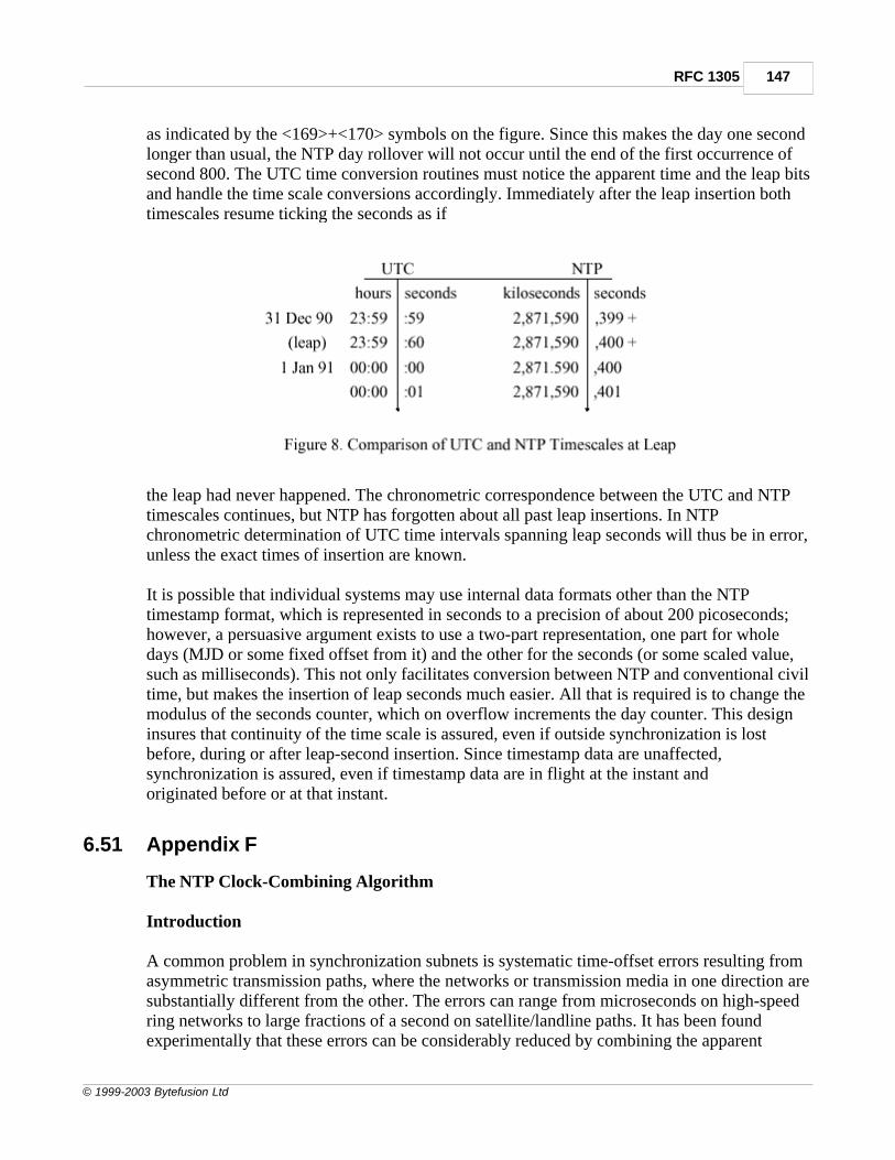
RFC 1305 147
© 1999-2003 Bytefusion Ltd
as indicated by the <169>+<170> symbols on the figure. Since this makes the day one secondlonger than usual, the NTP day rollover will not occur until the end of the first occurrence ofsecond 800. The UTC time conversion routines must notice the apparent time and the leap bitsand handle the time scale conversions accordingly. Immediately after the leap insertion bothtimescales resume ticking the seconds as if
the leap had never happened. The chronometric correspondence between the UTC and NTPtimescales continues, but NTP has forgotten about all past leap insertions. In NTPchronometric determination of UTC time intervals spanning leap seconds will thus be in error,unless the exact times of insertion are known.
It is possible that individual systems may use internal data formats other than the NTPtimestamp format, which is represented in seconds to a precision of about 200 picoseconds;however, a persuasive argument exists to use a two-part representation, one part for wholedays (MJD or some fixed offset from it) and the other for the seconds (or some scaled value,such as milliseconds). This not only facilitates conversion between NTP and conventional civiltime, but makes the insertion of leap seconds much easier. All that is required is to change themodulus of the seconds counter, which on overflow increments the day counter. This designinsures that continuity of the time scale is assured, even if outside synchronization is lostbefore, during or after leap-second insertion. Since timestamp data are unaffected,synchronization is assured, even if timestamp data are in flight at the instant andoriginated before or at that instant.
6.51 Appendix F
The NTP Clock-Combining Algorithm
Introduction
A common problem in synchronization subnets is systematic time-offset errors resulting fromasymmetric transmission paths, where the networks or transmission media in one direction aresubstantially different from the other. The errors can range from microseconds on high-speedring networks to large fractions of a second on satellite/landline paths. It has been foundexperimentally that these errors can be considerably reduced by combining the apparent

PresenTense Server148
© 1999-2003 Bytefusion Ltd
offsets of a number of time servers to produce a more accurate working offset. Following is adescription of the combining method used in the NTP implementation for the Fuzzball[MIL88b]. The method is similar to that used by national standards laboratories to determine asynthetic laboratory time scale from an ensemble of cesium clocks [ALL74b]. Theseprocedures are optional and not required in a conforming NTP implementation.
In the following description the stability of a clock is how well it can maintain a constantfrequency, the accuracy is how well its frequency and time compare with national standardsand the precision is how precisely these quantities can be maintained within a particulartimekeeping system. Unless indicated otherwise, The offset of two clocks is the timedifference between them, while the skew is the frequency difference (first derivative of offsetwith time) between them. Real clocks exhibit some variation in skew (second derivative ofoffset with time), which is called drift.
Determining Time and Frequency
Figure 9 shows the overall organization of the NTP time-server model. Timestamps exchangedwith possibly many other subnet peers are used to determine individual roundtrip delays andclock offsets relative to each peer as described in the NTP specification. As shown in thefigure, the computed delays and offsets are processed by the clock filter to reduce incidentaltiming noise and the most accurate and reliable subset determined by the clock-selectionalgorithm. The resulting offsets of this subset are first combined as described below and thenprocessed by the phase-locked loop (PLL). In the PLL the combined effects of the filtering,selection and combining operations is to produce a phase-correction term. This is processed bythe loop filter to control the local clock, which functions as a voltage-controlled oscillator(VCO). The VCO furnishes the timing (phase) reference to produce the timestamps used in allcalculations.
Clock Modelling
The International Standard (SI) definition of time interval is in terms of the standard second:the duration of 9,192,631,770 periods of the radiation corresponding to the transition betweenthe two hyperfine levels of the ground state of the cesium-133 atom. Let u represent thestandard unit of time interval so defined and v = 1 over u be the standard unit of frequency.The epoch, denoted by t, is defined as the reading of a counter that runs at frequency v and

RFC 1305 149
© 1999-2003 Bytefusion Ltd
began counting at some agreed initial epoch t0, which defines the standard or absolute timescale. For the purposes of the following analysis, the epoch of the standard time scale, as wellas the time indicated by a clock will be considered continuous. In practice, time is determinedrelative to a clock constructed from an atomic oscillator and system of counter/dividers, whichdefines a time scale associated with that particular oscillator. Standard time and frequency arethen determined from an ensemble of such timescales and algorithms designed to combinethem to produce a composite time scale approximating the standard time scale.
Let T(t) be the time displayed by a clock at epoch t relative to the standard time scale:
T(t) = 1/2 D(t sub 0 )[t - t sub 0 ] sup 2 + R(t sub 0 )[t - t sub 0 ] + T(t sub 0 ) + x(t),
where D(t sub 0 ) is the fractional frequency drift per unit time, R(t sub 0 ) the frequency andT(t sub 0 ) the time at some previous epoch t0. In the usual stationary model these quantitiescan be assumed constant or changing slowly with epoch. The random nature of the clock ischaracterized by x(t), which represents the random noise (jitter) relative to the standard timescale. In the usual analysis the second-order term D(t sub 0 ) is ignored and the noise term x(t)modelled as a normal distribution with predictable spectral density or autocorrelation function.
The probability density function of time offset p (t - T(t)) usually appears as a bell-shapedcurve centered somewhere near zero. The width and general shape of the curve aredetermined by x(t), which depends on the oscillator precision and jitter characteristics, as wellas the measurement system and its transmission paths. Beginning at epoch t0 the offset is setto zero, following which the bell creeps either to the left or right, depending on the value ofR(t sub 0 ) and accelerates depending on the value of D(t sub 0 ).
Development of a Composite Timescale
Now consider the time offsets of a number of real clocks connected by real networks. Adisplay of the offsets of all clocks relative to the standard time scale will appear as a system ofbell-shaped curves slowly precessing relative to each other, but with some further away fromnominal zero than others. The bells will normally be scattered over the offset space, more orless close to each other, with some overlapping and some not. The problem is to estimate thetrue offset relative to the standard time scale from a system of offsets collected routinelybetween the clocks.
A composite time scale can be determined from a sequence of offsets measured between the nclocks of an ensemble at nominal intervals tau. Let R sub i (t sub 0 ) be the frequency and Tsub i (t sub 0 ) the time of the ith clock at epoch t0 relative to the standard time scale and let"^" designate the associated estimates. Then, an estimator for Ti computed at t0 for epoch tsub 0 + tau is
neglecting second-order terms. Consider a set of n independent time-offset measurements

PresenTense Server150
© 1999-2003 Bytefusion Ltd
made between the clocks at epoch t sub 0 + tau and let the offset between clock i and clock j atthat epoch be T sub ij (t sub 0 + tau ), defined as
Note that T sub ij = - T sub ji and T sub ii = 0. Let w sub i ( tau ) be a previously determinedweight factor associated with the ith clock for the nominal interval tau. The basis for newestimates at epoch t sub 0 + tau is
That is, the apparent time indicated by the jth clock is a weighted average of the estimatedtime of each clock at epoch t sub 0 + tau plus the time offset measured between the jth clockand that clock at epoch t sub 0 + tau.
An intuitive grasp of the behavior of this algorithm can be gained with the aid of a fewexamples. For instance, if w sub i ( tau ) is unity for the ith clock and zero for all others, theapparent time for each of the other clocks is simply the estimated time T hat sub i (t sub 0 +tau ). If w sub i ( tau ) is zero for the ith clock, that clock can never affect any other clock andits apparent time is determined entirely from the other clocks. If w sub i ( tau ) = 1 / n for all i,the apparent time of the ith clock is equal to the average of the time estimates computed at t0plus the average of the time offsets measured to all other clocks. Finally, in a system with twoclocks and w sub i ( tau ) = 1 / 2 for each, and if the estimated time at epoch t sub 0 + tau isfast by 1 s for one clock and slow by 1 s for the other, the apparent time for both clocks willcoincide with the standard time scale.
In order to establish a basis for the next interval tau, it is necessary to update the frequencyestimate R hat sub i (t sub 0 + tau ) and weight factor w sub i ( tau ). The average frequencyassumed for the ith clock during the previous interval tau is simply the difference between thetimes at the beginning and end of the interval divided by tau. A good estimator for R sub i (tsub 0 + tau ) has been found to be the exponential average of these differences, which is givenby
R hat sub i (t sub 0 + tau ) = R hat sub i (t sub 0 ) + alpha sub i [ R hat sub i (t sub 0 ) - {T subi (t sub 0 + tau ) - T sub i (t sub 0 )} over tau ],
where alpha sub i is an experimentally determined weight factor which depends on theestimated frequency error of the ith clock. In order to calculate the weight factor w sub i ( tau), it is necessary to determine the expected error epsilon sub i ( tau ) for each clock. In thefollowing, braces "|" indicate absolute value and brackets "<>" indicate the infinite timeaverage. In practice, the infinite averages are computed as exponential time averages. An

RFC 1305 151
© 1999-2003 Bytefusion Ltd
estimate of the magnitude of the unbiased error of the ith clock accumulated over the nominalinterval tau is
where epsilon sub i ( tau ) and epsilon sub e ( tau ) are the accumulated error of the ith clockand entire clock ensemble, respectively. The accumulated error of the entire ensemble is
Finally, the weight factor for the ith clock is calculated as
When all estimators and weight factors have been updated, the origin of the estimation intervalis shifted and the new value of t0 becomes the old value of t sub 0 + tau.
While not entering into the above calculations, it is useful to estimate the frequency error,since the ensemble clocks can be located some distance from each other and become isolatedfor some time due to network failures. The frequency-offset error in Ri is equivalent to thefractional frequency yi,
y sub i = { nu sub i~-~nu sub I } over nu sub I
measured between the ith time scale and the standard time scale I. Temporarily dropping thesubscript i for clarity, consider a sequence of N independent frequency-offset samples y(j) (j=1, 2,... ,N) where the interval between samples is uniform and equal to T. Let tau be thenominal interval over which these samples are averaged. The Allan variance sigma sub y sup2 ( N,T,tau ) [ALL74a] is defined as

PresenTense Server152
© 1999-2003 Bytefusion Ltd
A particularly useful formulation is N = 2 and T = tau:
so that
While the Allan variance has found application when estimating errors in ensembles of cesiumclocks, its application to NTP is limited due to the computation and storage burden. Asdescribed in the next section, it is possible to estimate errors with some degree of confidenceusing normal byproducts of NTP processing algorithms.
Application to NTP
The NTP clock model is somewhat less complex than the general model described above. Forinstance, at the present level of development it is not necessary to separately estimate the timeand frequency of all peer clocks, only the time and frequency of the local clock. If thetimekeeping reference is the local clock itself, then the offsets available in the peer.offset peervariables can be used directly for the T sub ij quantities above. In addition, the NTP local-clock model incorporates a type-II phase-locked loop, which itself reliably estimates frequencyerrors and corrects accordingly. Thus, the requirement for estimating frequency is entirelyeliminated.
There remains the problem of how to determine a robust and easily computable error estimateepsilon sub i. The method described above, although analytically justified, is most difficult toimplement. Happily, as a byproduct of the NTP clock-filter algorithm, a useful error estimateis available in the form of the dispersion. As described in the NTP specification, the dispersionincludes the absolute value of the weighted average of the offsets between the chosen offsetsample and the n-1 other samples retained for selection. The effectiveness of this estimatorwas compared with the above estimator by simulation using observed timekeeping data andfound to give quite acceptable results.

RFC 1305 153
© 1999-2003 Bytefusion Ltd
The NTP clock-combining algorithm can be implemented with only minor modifications tothe algorithms as described in the NTP specification. Although elsewhere in the NTPspecification the use of general-purpose multiply/divide routines has been successfullyavoided, there seems to be no way to avoid them in the clock-combining algorithm. However,for best performance the local-clock algorithm described elsewhere in this document shouldbe implemented as well, since the combining algorithms result in a modest increase in phasenoise which the revised local-clock algorithm is designed to suppress.
Clock-Combining Procedure
The result of the NTP clock-selection procedure is a set of survivors (there must be at leastone) that represent truechimers, or correct clocks. When clock combining is not implemented,one of these peers, chosen as the most likely candidate, becomes the synchronization sourceand its computed offset becomes the final clock correction. Subsequently, the system variablesare adjusted as described in the NTP clock-update procedure. When clock combining isimplemented, these actions are unchanged, except that the final clock correction is computedby the clock-combining procedure.
The clock-combining procedure is called from the clock-select procedure. It constructs fromthe variables of all surviving peers the final clock correction THETA. The estimated errorrequired by the algorithms previously described is based on the synchronization distanceLAMBDA computed by the distance procedure, as defined in the NTP specification. Thereciprocal of LAMBDA is the weight of each clock-offset contribution to the final clockcorrection. The following pseudo-code describes the procedure.
begin clock-combining procedure temp1 <-- 0; temp2 <-- 0; for (each peer remaining on the candidate list) /* scan all survivors */ LAMBDA <-- distance (peer); temp <-- 1 over peer.stratum * NTP.MAXDISPERSE + LAMBDA; temp1 <-- temp1 + temp; /* update weight and offset */ temp2 <-- temp2 + temp * peer.offset; endif; THETA <-- temp2 over temp1;/* compute final correction */end clock-combining procedure;
The value THETA is the final clock correction used by the local-clock procedure to adjust theclock.
6.52 Appendix G
Computer Clock Modelling and Analysis
A computer clock includes some kind of reference oscillator, which is stabilized by a quartz

PresenTense Server154
© 1999-2003 Bytefusion Ltd
crystal or some other means, such as the power grid. Usually, the clock includes a prescaler,which divides the oscillator frequency to a standard value, such as 1 MHz or 100 Hz, and acounter, implemented in hardware, software or some combination of the two, which can beread by the processor. For systems intended to be synchronized to an external source ofstandard time, there must be some means to correct the phase and frequency by occasionalvernier adjustments produced by the timekeeping protocol. Special care is necessary in alltimekeeping system designs to insure that the clock indications are always monotonicallyincreasing; that is, system time never "runs backwards."
Computer Clock Models
The simplest computer clock consists of a hardware latch which is set by overflow of ahardware counter or prescaler, and causes a processor interrupt or tick. The latch is reset whenacknowledged by the processor, which then increments the value of a software clock counter.The phase of the clock is adjusted by adding periodic corrections to the counter as necessary.The frequency of the clock can be adjusted by changing the value of the increment itself, inorder to make the clock run faster or slower. The precision of this simple clock model islimited to the tick interval, usually in the order of 10 ms; although in some systems the tickinterval can be changed using a kernel variable.
This software clock model requires a processor interrupt on every tick, which can causesignificant overhead if the tick interval is small, say in the order less 1 ms with the newerRISC processors. Thus, in order to achieve timekeeping precisions less than 1 ms, some kindof hardware assist is required. A straightforward design consists of a voltage-controlledoscillator (VCO), in which the
frequency is controlled by a buffered, digital/analog converter (DAC). Under the assumption

RFC 1305 155
© 1999-2003 Bytefusion Ltd
that the VCO tolerance is 10-4 or 100 parts-per-million (ppm) (a reasonable value forinexpensive crystals) and the precision required is 100 us (a reasonable goal for a RISCprocessor), the DAC must include at least ten bits.
A design sketch of a computer clock constructed entirely of hardware logic components isshown in Figure 10a. The clock is read by first pulsing the read signal, which latches thecurrent value of the clock counter, then adding the contents of the clock-counter latch and a64-bit clock-offset variable, which is maintained in processor memory. The clock phase isadjusted by adding a correction to the clock-offset variable, while the clock frequency isadjusted by loading a correction to the DAC latch. In principle, this clock model can beadapted to any precision by changing the number of bits of the prescaler or clock counter orchanging the VCO frequency. However, it does not seem useful to reduce precision muchbelow the minimum interrupt latency, which is in the low microseconds for a modern RISCprocessor.
If it is not possible to vary the oscillator frequency, which might be the case if the oscillator isan external frequency standard, a design such as shown in Figure 10b may be used. It includesa fixed-frequency oscillator and prescaler which includes a dual-modulus swallow counter thatcan be operated in either divide-by-10 or divide-by-11 modes as controlled by a pulseproduced by a programmable divider (PD). The PD is loaded with a value representing thefrequency offset. Each time the divider overflows a pulse is produced which switches theswallow counter from the divide-by-10 mode to the divide-by-11 mode and then back again,which in effect "swallows" or deletes a single pulse of the prescaler pulse train.
The pulse train produced by the prescaler is controlled precisely over a small range by thecontents of the PD. If programmed to emit pulses at a low rate, relatively few pulses areswallowed per second and the frequency counted is near the upper limit of its range; while, ifprogrammed to emit pulses at a high rate, relatively many pulses are swallowed and thefrequency counted is near the lower limit. Assuming some degree of freedom in the choice ofoscillator frequency and prescaler ratios, this design can compensate for a wide range ofoscillator frequency tolerances.
In all of the above designs it is necessary to limit the amount of adjustment incorporated inany step to insure that the system clock indications are always monotonically increasing. Withthe software clock model this is assured as long as the increment is never negative. When themagnitude of a phase adjustment exceeds the tick interval (as corrected for the frequencyadjustment), it is necessary to spread the adjustments over multiple tick intervals. This strategyamounts to a deliberate frequency offset sustained for an interval equal to the total number ofticks required and, in fact, is a feature of the Unix clock model discussed below.
In the hardware clock models the same considerations apply; however, in these designs thetick interval amounts to a single pulse at the prescaler output, which may be in the order of 1ms. In order to avoid decreasing the indicated time when a negative phase correction occurs, itis necessary to avoid modifying the clock-offset variable in processor memory and to confineall adjustments to the VCO or prescaler. Thus, all phase adjustments must be performed bymeans of programmed frequency adjustments in much the same way as with the softwareclock model described previously.
PresenTense Server156
© 1999-2003 Bytefusion Ltd
It is interesting to conjecture on the design of a processor assist that could provide all of theabove functions in a compact, general-purpose hardware interface. The interface might consistof a multifunction timer chip such as the AMD 9513A, which includes five 16-bit counters,each with programmable load and hold registers, plus an onboard crystal oscillator, prescalerand control circuitry. A 48-bit hardware clock counter would utilize three of the 16-bitcounters, while the fourth would be used as the swallow counter and the fifth as theprogrammable divider. With the addition of a programmable-array logic device andarchitecture-specific host interface, this compact design could provide all the functionsnecessary for a comprehensive timekeeping system.
The Fuzzball Clock Model
The Fuzzball clock model uses a combination of hardware and software to provide precisiontiming with a minimum of software and processor overhead. The model includes an oscillator,prescaler and hardware counter; however, the oscillator frequency remains constant and thehardware counter produces only a fraction of the total number of bits required by the clockcounter. A typical design uses a 64-bit software clock counter and a 16-bit hardware counterwhich counts the prescaler output. A hardware-counter overflow causes the processor toincrement the software counter at the bit corresponding to the frequency 2N f p, where N is thenumber of bits of the hardware counter and fp is the counted frequency at the prescaler output.The processor reads the clock counter by first generating a read pulse, which latches thehardware counter, and then adding its contents, suitably aligned, to the software counter.
The Fuzzball clock can be corrected in phase by adding a (signed) adjustment to the softwareclock counter. In practice, this is done only when the local time is substantially different fromthe time indicated by the clock and may violate the monotonicity requirement. Vernier phaseadjustments determined in normal system operation must be limited to no more than theperiod of the counted frequency, which is 1 kHz for LSI-11 Fuzzballs. In the Fuzzball modelthese adjustments are performed at intervals of 4 s, called the adjustment interval, whichprovides a maximum frequency adjustment range of 250 ppm. The adjustment opportunitiesare created using the interval-timer facility, which is a feature of most operating systems andindependent of the time-of-day clock. However, if the counted frequency is increased from 1kHz to 1 MHz for enhanced precision, the adjustment frequency must be increased to 250 Hz,which substantially increases processor overhead. A modified design suitable for highprecision clocks is presented in the next section.
In some applications involving the Fuzzball model, an external pulse-per-second (pps) signalis available from a reference source such as a cesium clock or GPS receiver. Such a signalgenerally provides much higher accuracy than the serial character string produced by a radiotimecode receiver, typically in the low nanoseconds. In the Fuzzball model this signal isprocessed by an interface which produces a hardware interrupt coincident with the arrival ofthe pps pulse. The processor then reads the clock counter and computes the residual modulo 1s of the clock counter. This represents the local-clock error relative to the pps signal.
Assuming the seconds numbering of the clock counter has been determined by a reliablesource, such as a timecode receiver, the offset within the second is determined by the residualcomputed above. In the NTP local-clock model the timecode receiver or NTP establishes the

RFC 1305 157
© 1999-2003 Bytefusion Ltd
time to within ±128 ms, called the aperture, which guarantees the seconds numbering towithin the second. Then, the pps residual can be used directly to correct the oscillator, sincethe offset must be less than the aperture for a correctly operating timecode receiver and ppssignal.
The above technique has an inherent error equal to the latency of the interrupt system, whichin modern RISC processors is in the low tens of microseconds. It is possible to improveaccuracy by latching the hardware time-of-day counter directly by the pps pulse and thenreading the counter in the same way as usual. This requires additional circuitry to prioritize thepps signal relative to the pulse generated by the program to latch the counter.
The Unix Clock Model
The Unix 4.3bsd clock model is based on two system calls, settimeofday and adjtime, togetherwith two kernel variables tick and tickadj. The settimeofday call unceremoniously resets thekernel clock to the value given, while the adjtime call slews the kernel clock to a new valuenumerically equal to the sum of the present time of day and the (signed) argument given in theadjtime call. In order to understand the behavior of the Unix clock as controlled by theFuzzball clock model described above, it is helpful to explore the operations of adjtime inmore detail.
The Unix clock model assumes an interrupt produced by an onboard frequency source, suchas the clock counter and prescaler described previously, to deliver a pulse train in the 100-Hzrange. In principle, the power grid frequency can be used, although it is much less stable thana crystal oscillator. Each interrupt causes an increment called tick to be added to the clockcounter. The value of the increment is chosen so that the clock counter, plus an initial offsetestablished by the settimeofday call, is equal to the time of day in microseconds.
The Unix clock can actually run at three different rates, one corresponding to tick, which isrelated to the intrinsic frequency of the particular oscillator used as the clock source, one totick + tickadj and the third to tick -tickadj. Normally the rate corresponding to tick is used;but, if adjtime is called, the argument delta given is used to calculate an interval DELTA t =delta tick over tickadj during which one or the other of the two rates are used, depending onthe sign of delta. The effect is to slew the clock to a new value at a small, constant rate, ratherthan incorporate the adjustment all at once, which could cause the clock to be set backward.With common values of tick = 10 ms and tickadj = 5 us, the maximum frequency adjustmentrange is ± tickadj over tick = +- {5 x 10⁻⁶} over {10-2} or ±500 ppm. Even larger ranges maybe required in the case of some workstations (e.g., SPARC stations) with extremely poorcomponent tolerances.
When precisions not less than about 1 ms are required, the Fuzzball clock model can beadapted to the Unix model by software simulation, as described in Section 5 of the NTPspecification, and calling adjtime at each adjustment interval. When precisions substantiallybetter than this are required, the hardware microsecond clock provided in some workstationscan be used together with certain refinements of the Fuzzball and Unix clock models. Theparticular design described below is appropriate for a maximum oscillator frequency toleranceof 100 ppm (.01%), which can be

PresenTense Server158
© 1999-2003 Bytefusion Ltd
obtained using a relatively inexpensive quartz crystal oscillator, but is readily scalable for otherassumedtolerances.
The clock model requires the capability to slew the clock frequency over the range ±100 ppmwith an intrinsic oscillator frequency error as great as ±100 ppm. Figure 11 shows the timingrelationships at the extremes of the requirements envelope. Starting from an assumed offset ofnominal zero and an assumed error of +100 ppm at time 0 s, the line AC shows how theuncorrected offset grows with time. Let sigma represent the adjustment interval and a theinterval AB, in seconds, and let r be the slew, or rate at which corrections are introduced, inppm. For an accuracy specification of 100 us, then
The line AE represents the extreme case where the clock is to be steered -100 ppm. Since theslew must be complete at the end of the adjustment interval,
These relationships are satisfied only if r > 200 ppm and sigma < 2 s. Using r = 300 ppm forconvenience, sigma = 1.5 s and a < 0.5 s. For the Unix clock model with tick = 10 ms, thisresults in the value of tickadj = 3us.
One of the assumptions made in the Unix clock model is that the period of adjustmentcomputed in the adjtime call must be completed before the next call is made. If not, this
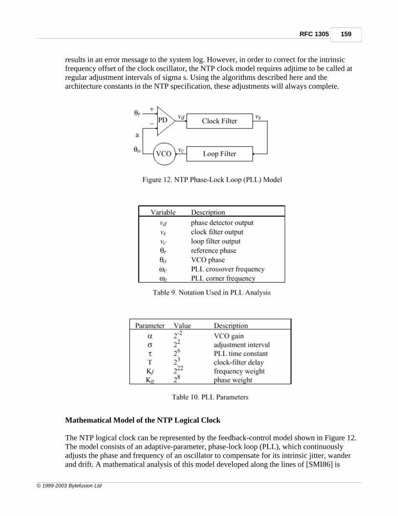
RFC 1305 159
© 1999-2003 Bytefusion Ltd
results in an error message to the system log. However, in order to correct for the intrinsicfrequency offset of the clock oscillator, the NTP clock model requires adjtime to be called atregular adjustment intervals of sigma s. Using the algorithms described here and thearchitecture constants in the NTP specification, these adjustments will always complete.
Mathematical Model of the NTP Logical Clock
The NTP logical clock can be represented by the feedback-control model shown in Figure 12.The model consists of an adaptive-parameter, phase-lock loop (PLL), which continuouslyadjusts the phase and frequency of an oscillator to compensate for its intrinsic jitter, wanderand drift. A mathematical analysis of this model developed along the lines of [SMI86] is

PresenTense Server160
© 1999-2003 Bytefusion Ltd
presented in following sections, along with a design example useful for implementationguidance in operating-systems environments such as Unix and Fuzzball. Table 9 summarizesthe quantities ordinarily treated as variables in the model. By convention, v is used for internalloop variables, theta for phase, omega for frequency and tau for time. Table 10 summarizesthose quantities ordinarily fixed as constants in the model. Note that these are all expressed asa power of two in order to simplify the implementation.
In Figure 12 the variable theta sub r represents the phase of the reference signal and theta subo the phase of the voltage-controlled oscillator (VCO). The phase detector (PD) produces avoltage v sub d representing the phase difference theta sub r - theta sub o . The clock filterfunctions as a tapped delay line, with the output v sub s taken at the tap selected by the clock-filter algorithm described in the NTP specification. The loop filter, represented by theequations given below, produces a VCO correction voltage v sub c, which controls theoscillator frequency and thus the phase theta sub o.
The PLL behavior is completely determined by its open-loop, Laplace transfer function G(s) inthe s domain. Since both frequency and phase corrections are required, an appropriate designconsists of a type-II PLL, which is defined by the function
where omega sub c is the crossover frequency (also called loop gain), omega sub z is thecorner frequency (required for loop stability) and tau determines the PLL time constant andthus the bandwidth. While this is a first-order function and some improvement in phase noisemight be gained from a higher-order function, in practice the improvement is lost due to theeffects of the clock-filter delay, as described below.
The open-loop transfer function G(s) is constructed by breaking the loop at point a on Figure12 and computing the ratio of the output phase theta sub o (s) to the reference phase theta subr (s). This function is the product of the individual transfer functions for the phase detector,clock filter, loop filter and VCO. The phase detector delivers a voltage v sub d (t) = theta sub r(t), so its transfer function is simply F sub d (s) = 1, expressed in V/rad. The VCO delivers afrequency change DELTA omega = { d theta sub o (t)} over {dt} = alpha {v sub c (t)}, wherealpha is the VCO gain in rad/V-sec and theta sub o (t) = alpha int v sub c (t) dt. Its transferfunction is the Laplace transform of the integral, F sub o (s) = alpha over s, expressed inrad/V. The clock filter contributes a stochastic delay due to the clock-filter algorithm; but, forpresent purposes, this delay will be assumed a constant T, so its transfer function is theLaplace transform of the delay, F sub s (s) = e sup {- Ts}. Let F(s) be the transfer function ofthe loop filter, which has yet to be determined. The open-loop transfer function G(s) is theproduct of these four individual transfer functions:
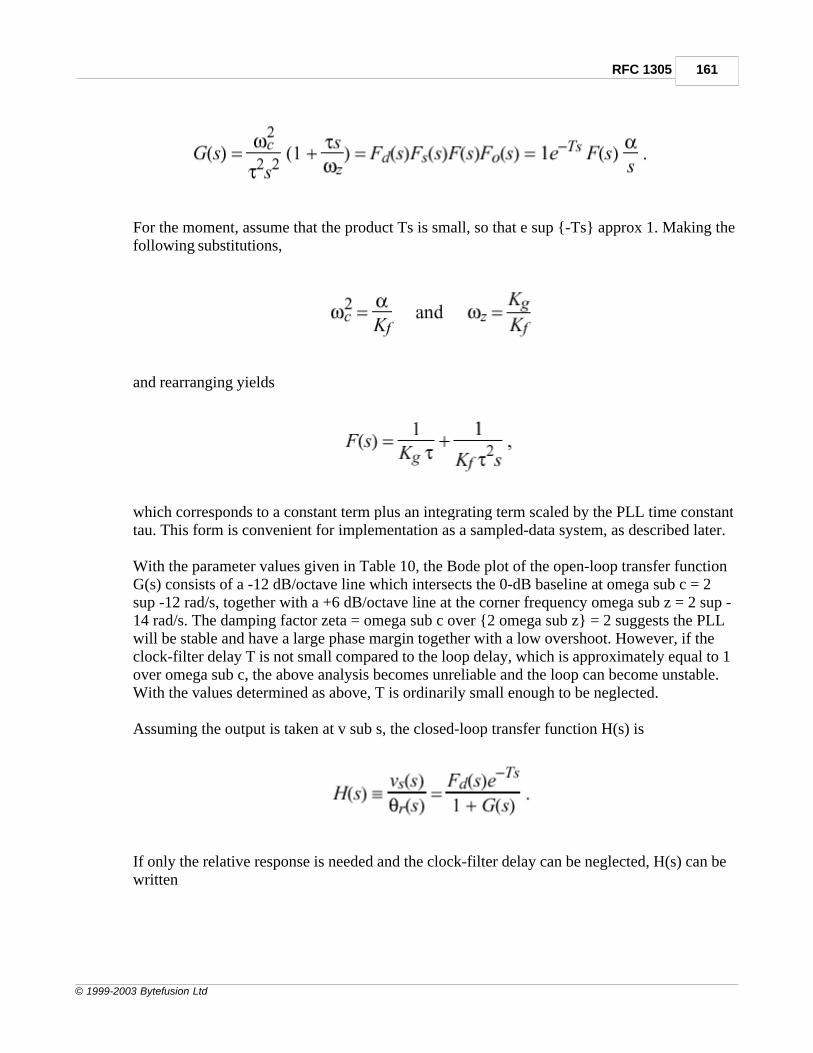
RFC 1305 161
© 1999-2003 Bytefusion Ltd
For the moment, assume that the product Ts is small, so that e sup {-Ts} approx 1. Making thefollowing substitutions,
and rearranging yields
which corresponds to a constant term plus an integrating term scaled by the PLL time constanttau. This form is convenient for implementation as a sampled-data system, as described later.
With the parameter values given in Table 10, the Bode plot of the open-loop transfer functionG(s) consists of a -12 dB/octave line which intersects the 0-dB baseline at omega sub c = 2sup -12 rad/s, together with a +6 dB/octave line at the corner frequency omega sub z = 2 sup -14 rad/s. The damping factor zeta = omega sub c over {2 omega sub z} = 2 suggests the PLLwill be stable and have a large phase margin together with a low overshoot. However, if theclock-filter delay T is not small compared to the loop delay, which is approximately equal to 1over omega sub c, the above analysis becomes unreliable and the loop can become unstable.With the values determined as above, T is ordinarily small enough to be neglected.
Assuming the output is taken at v sub s, the closed-loop transfer function H(s) is
If only the relative response is needed and the clock-filter delay can be neglected, H(s) can bewritten

PresenTense Server162
© 1999-2003 Bytefusion Ltd
For some input function I(s) the output function I(s)H(s) can be inverted to find the timeresponse. Using a unit-step input I(s) = 1 over s and the values determined as above, Thisyields a PLL rise time of about 52 minutes, a maximum overshoot of about 4.8 percent inabout 1.7 hours and a settling time to within one percent of the initial offset in about 8.7 hours.
Parameter Management
A very important feature of the NTP PLL design is the ability to adapt its behavior to matchthe prevailing stability of the local oscillator and transmission conditions in the network. Thisis done using the <$Ealpha> and <$Etau> parameters shown in Table 10. Mechanisms fordoing this are described in following sections.
Adjusting VCO Gain
The alpha parameter is determined by the maximum frequency tolerance of the local oscillatorand the maximum jitter requirements of the timekeeping system. This parameter is usually anarchitecture constant and fixed during system operation. In the implementation modeldescribed below, the reciprocal of alpha, called the adjustment interval sigma, determines thetime between corrections of the local clock, and thus the value of alpha. The value of sigmacan be determined by the following procedure.
The maximum frequency tolerance for board-mounted, uncompensated quartz-crystaloscillators is probably in the range of 10-4 (100 ppm). Many if not most Internet timekeepingsystems can tolerate jitter to at least the order of the intrinsic local-clock resolution, calledprecision in the NTP specification, which is commonly in the range from one to 20 ms.Assuming 10-3 s peak-to-peak as the most demanding case, the interval between clockcorrections must be no more than sigma = 10 sup -3 over {2 x 10 sup -4} = 5 sec. For theNTP reference model sigma = 4 sec in order to allow for known features of the Unixoperating-system kernel. However, in order to support future anticipated improvements inaccuracy possible with faster workstations, it may be useful to decrease sigma to as little asone-tenth the present value.
Note that if sigma is changed, it is necessary to adjust the parameters K sub f and K sub g inorder to retain the same loop bandwidth; in particular, the same omega sub c and omega sub z.Since alpha varies as the reciprocal of sigma, if sigma is changed to something other than 22,as in Table 10, it is necessary to divide both K sub f and K sub g by sigma over 4 to obtain thenew values.
Adjusting PLL Bandwidth

RFC 1305 163
© 1999-2003 Bytefusion Ltd
A key feature of the type-II PLL design is its capability to compensate for the intrinsicfrequency errors of the local oscillator. This requires a initial period of adaptation in order torefine the frequency estimate (see later sections of this appendix). The tau parameterdetermines the PLL time constant and thus the loop bandwidth, which is approximately equalto {omega sub c} over tau. When operated with a relatively large bandwidth small tau, as inthe analysis above, the PLL adapts quickly to changes in the input reference signal, but haspoor long term stability. Thus, it is possible to accumulate substantial errors if the system isdeprived of the reference signal for an extended period. When operated with a relatively smallbandwidth large tau, the PLL adapts slowly to changes in the input reference signal, and mayeven fail to lock onto it. Assuming the frequency estimate has stabilized, it is possible for thePLL to coast for an extended period without external corrections and without accumulatingsignificant error.
In order to achieve the best performance without requiring individual tailoring of the loopbandwidth, it is necessary to compute each value of tau based on the measured values ofoffset, delay and dispersion, as produced by the NTP protocol itself. The traditional way ofdoing this in precision timekeeping systems based on cesium clocks, is to relate tau to theAllan variance, which is defined
as the mean of the first-order differences of sequential samples measured during a specifiedinterval tau,
where y is the fractional frequency measured with respect to the local time scale and N is thenumber of samples.

PresenTense Server164
© 1999-2003 Bytefusion Ltd
In the NTP local-clock model the Allan variance (called the compliance, h in Table 11) isapproximated on a continuous basis by exponentially averaging the first-order differences ofthe offset samples using an empirically determined averaging constant. Using somewhat ad-hoc mapping functions determined from simulation and experience, the compliance ismanipulated to produce the loop time constant and update interval.
The NTP Clock Model
The PLL behavior can also be described by a set of recurrence equations, which depend uponseveral variables and constants. The variables and parameters used in these equations areshown in Tables 9, 10 and 11. Note the use of powers of two, which facilitates implementationusing arithmetic shifts and avoids the requirement for a multiply/divide capability.
A capsule overview of the design may be helpful in understanding how it operates. The logicalclock is continuously adjusted in small increments at fixed intervals of sigma. The incrementsare determined while updating the variables shown in Tables 9 and 11, which are computedfrom received NTP messages as described in the NTP specification. Updates computed fromthese messages occur at discrete times as each is received. The intervals mu between updatesare variable and can range up to about 17 minutes. As part of update processing thecompliance h is computed and used to adjust the PLL time constant tau. Finally, the updateinterval rho for transmitted NTP messages is determined as a fixed multiple of tau.
Updates are numbered from zero, with those in the neighborhood of the ith update shown inFigure 13. All variables are initialized at i = 0 to zero, except the time constant tau (0) = tau,poll interval mu (0) = tau (from Table 10) and compliance h (0) = K sub s. After an intervalmu (i)> ( i > 0) from the previous update the ith update arrives at time t(i) including the timeoffset v sub s (i). Then, after an interval mu (i +1) the i+1th update arrives at time t(i + 1)including the time offset v sub s (i + 1). When the update v sub s (i) is received, the frequencyerror f(i + 1) and phase error g(i+1) are computed:
Note that these computations depend on the value of the time constant tau (i)> and pollinterval mu (i) previously computed from the i-1th update. Then, the time constant for the nextinterval is computed from the current value of the compliance h(i)

RFC 1305 165
© 1999-2003 Bytefusion Ltd
Next, using the new value of tau, called tau prime to avoid confusion, the poll interval iscomputed
Finally, the compliance h(i + 1) is recomputed for use in the i+1th update:
The factor tau prime in the above has the effect of adjusting the bandwidth of the PLL as afunction of compliance. When the compliance has been low over some relatively long period,tau prime is increased and the bandwidth is decreased. In this mode small timing fluctuationsdue to jitter in the network are suppressed and the PLL attains the most accurate frequencyestimate. On the other hand, if the compliance becomes high due to greatly increased jitter ora systematic frequency offset, tau prime is decreased and the bandwidth is increased. In thismode the PLL is most adaptive to transients which can occur due to reboot of the system or amajor timing error. In order to maintain optimum stability, the poll interval rho is varieddirectly with tau.
A model suitable for simulation and parameter refinement can be constructed from the aboverecurrence relations. It is convenient to set the temporary variable a = g(i +1). At eachadjustment interval sigma the quantity a over K sub g + {f(i + 1)} over K sub f is added to thelocal-clock phase and the quantity a over K sub g is subtracted from a. For convenience, let nbe the greatest integer in {mu (i)} over sigma; that is, the number of adjustments that occur inthe ith interval. Thus, at the end of the ith interval just before the i+1th update, the VCOcontrol voltage is:
Detailed simulation of the NTP PLL with the values specified in Tables 9, 10 and 11 and theclock filter described in the NTP specification results in the following characteristics: For a100-ms phase change the loop reaches zero error in 39 minutes, overshoots 7 ms at 54minutes and settles to less than 1 ms in about six hours. For a 50-ppm frequency change theloop reaches 1 ppm in about 16 hours and 0.1 ppm in about 26 hours. When the magnitude ofcorrection exceeds a few milliseconds or a few ppm for more than a few updates, thecompliance begins to increase, which causes the loop time constant and update interval todecrease. When the magnitude of correction falls below about 0.1 ppm for a few hours, the

PresenTense Server166
© 1999-2003 Bytefusion Ltd
compliance begins to decrease, which causes the loop time constant and update interval toincrease. The effect is to provide a broad capture range exceeding 4 s per day, yet thecapability to resolve oscillator skew well below 1 ms per day. These characteristics areappropriate for typical crystal-controlled oscillators with or without temperature compensationor oven control.
6.53 Appendix H
Analysis of Errors and Correctness Principles
Introduction
This appendix contains an analysis of errors arising in the generation and processing of NTPtimestamps and the determination of delays and offsets. It establishes error bounds as afunction of measured roundtrip delay and dispersion to the root (primary reference source) ofthe synchronization subnet. It also discusses correctness assertions about these error boundsand the time-transfer, filtering and selection algorithms used in NTP.
The notation w = [u,v] in the following describes the interval in which u is the lower limit andv the upper limit, inclusive. Thus, u = min (w) <= v = max (w), and for scalar a, w + a = [u +a, v + a]. Table 12 shows a summary of other notation used in the analysis. The notation <x>designates the (infinite) average of x, which is usually approximated by an exponentialaverage, while the notation x "hat" designates an estimator for x. The lower-case Greek letterstheta, delta and epsilon are used to designate measurement data for the local clock to a peerclock, while the upper-case Greek letters THETA, DELTA and EPSILON are used todesignate measurement data for the local clock relative to the primary reference source at theroot of the synchronization subnet. Exceptions will be noted as they arise.
Timestamp Errors
The standard second (1 s) is defined as "9,192,631,770 periods of the radiation correspondingto the transition between the two hyperfine levels of the ground state of the cesium-133 atom"[ALL74b], which implies a granularity of about 1.1x10⁻¹⁰ s. Other intervals can bedetermined as rational multiples of 1 s. While NTP time has an inherent resolution of about2.3x10-10 s, local clocks ordinarily have resolutions much worse than this, so the inherenterror in resolving NTP time relative to the 1 s can be neglected.
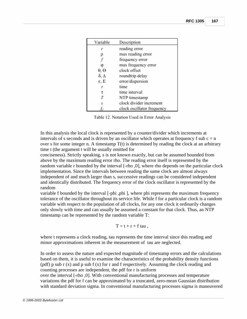
RFC 1305 167
© 1999-2003 Bytefusion Ltd
In this analysis the local clock is represented by a counter/divider which increments atintervals of s seconds and is driven by an oscillator which operates at frequency f sub c = nover s for some integer n. A timestamp T(t) is determined by reading the clock at an arbitrarytime t (the argument t will be usually omitted forconciseness). Strictly speaking, s is not known exactly, but can be assumed bounded fromabove by the maximum reading error rho. The reading error itself is represented by therandom variable r bounded by the interval [-rho ,0], where rho depends on the particular clockimplementation. Since the intervals between reading the same clock are almost alwaysindependent of and much larger than s, successive readings can be considered independentand identically distributed. The frequency error of the clock oscillator is represented by therandomvariable f bounded by the interval [-phi ,phi ], where phi represents the maximum frequencytolerance of the oscillator throughout its service life. While f for a particular clock is a randomvariable with respect to the population of all clocks, for any one clock it ordinarily changesonly slowly with time and can usually be assumed a constant for that clock. Thus, an NTPtimestamp can be represented by the random variable T:
T = t + r + f tau ,
where t represents a clock reading, tau represents the time interval since this reading andminor approximations inherent in the measurement of tau are neglected.
In order to assess the nature and expected magnitude of timestamp errors and the calculationsbased on them, it is useful to examine the characteristics of the probability density functions(pdf) p sub r (x) and p sub f (x) for r and f respectively. Assuming the clock reading andcounting processes are independent, the pdf for r is uniformover the interval [-rho ,0]. With conventional manufacturing processes and temperaturevariations the pdf for f can be approximated by a truncated, zero-mean Gaussian distributionwith standard deviation sigma. In conventional manufacturing processes sigma is maneuvered

PresenTense Server168
© 1999-2003 Bytefusion Ltd
so that the fraction of samples rejected outside the interval [-phi ,phi ] is acceptable. The pdffor the total timestamp error epsilon (x) is thus the sum of the r and f contributions, computedas
which appears as a bell-shaped curve, symmetric about -rho over 2 and bounded by theinterval
Since f changes only slowly over time for any single clock,
where epsilon without argument designates the interval and epsilon (x) designates the pdf. Inthe following development subscripts will be used on various quantities to indicate to whichentity or timestamp the quantity applies. Occasionally, epsilon will be used to designate anabsolute maximum error, rather than the interval, but the distinction will be clear fromcontext.
Measurement Errors
In NTP the roundtrip delay and clock offset between two peers A and B are determined by aprocedure in which timestamps are exchanged via the network paths between them. Theprocedure involves the four most recent timestamps numbered as shown in Figure 14, wherethe theta sub 0 represents the true clock offset of peer B relative to peer A. The T sub 1 and Tsub 4 timestamps are determined relative to the A clock, while the T sub 2 and T sub 3timestamps are determined relative to the B clock. The measured roundtrip delay delta andclock offset theta of B relative to A are given by

RFC 1305 169
© 1999-2003 Bytefusion Ltd
The errors inherent in determining the timestamps T1, T2, T3 and T4 are, respectively,
For specific peers A and B, where f sub A and f sub B can be considered constants, theinterval containing the maximum error inherent in determining delta is given by
In the NTP local clock model the residual frequency errors f sub A and f sub B are minimizedthrough the use of a type-II phase-lock loop (PLL). Under most conditions these errors will besmall and can be ignored. The pdf for the remaining errors is symmetric, so that delta "hat" =<delta> is an unbiased maximum-likelihood estimator for the true roundtrip delay,independent of the particular values of rho sub A and rho sub B.
However, in order to reliably bound the errors under all conditions of component variation andoperational regimes, the design of the PLL and the tolerance of its intrinsic oscillator must becontrolled so that it is not possible under any circumstances for f sub A or f sub B to exceedthe bounds [-phi sub A ,phi sub A ] or [-phi sub B ,phi sub B ], respectively. Setting rho =max ( rho sub A ,rho sub B ) for convenience, the absolute maximum error epsilon sub deltainherent in determining roundtrip delay delta is given by
neglecting residuals.
As in the case for delta, where f sub A and f sub B can be considered constants, the intervalcontaining the maximum error inherent in determining theta is given by
Under most conditions the errors due to f sub A and f sub B will be small and can be ignored.

PresenTense Server170
© 1999-2003 Bytefusion Ltd
If rho sub A = rho sub B = rho; that is, if both the A and B clocks have the same resolution,the pdf for the remaining errors is symmetric, so that theta "hat" = < theta > is an unbiasedmaximum-likelihood estimator for the true clock offset theta sub 0, independent of theparticular value of rho. If rho sub A != rho sub B, < theta > is not an unbiased estimator;however, the bias error is in the order of
and can usually be neglected.
Again setting rho = max ( rho sub A , rho sub B ) for convenience, the absolute maximumerror epsilon sub theta inherent in determining clock offset theta is given by
Network Errors
In practice, errors due to stochastic network delays usually dominate. In general, it is notpossible to characterize network delays as a stationary random process, since network queuescan grow and shrink in chaotic fashion and arriving customer traffic is frequently bursty.However, it is a simple exercise to calculate bounds on clock offseterrors as a function of measured delay. Let T sub 2 - T sub 1 = a and T sub 3 - T sub 4 = b.Then,
The true offset of B relative to A is called theta sub 0 in Figure 14. Let x denote the actualdelay between the departure of a message from A and its arrival at B. Therefore, x + theta sub0 = T sub 2 - T sub 1 == a . Since x must be positive in our universe, x = a - theta sub 0 >= 0,which requires theta sub 0 <= a. A similar argument requires that b <= theta sub 0, so surely b<= theta sub 0 <= a. This inequality can also be expressed
which is equivalent to

RFC 1305 171
© 1999-2003 Bytefusion Ltd
In the previous section bounds on delay and offset errors were determined. Thus, theinequality can be written
where epsilon sub theta is the maximum offset error and epsilon sub delta is the maximumdelay error derived previously. The quantity
called the peer dispersion, defines the maximum error in the inequality. Thus, the correctnessinterval I can be defined as the interval
in which the clock offset C = theta is the midpoint. By construction, the true offset theta sub 0must lie somewhere in this interval.
Inherited Errors
As described in the NTP specification, the NTP time server maintains the local clock THETA,together with the root roundtrip delay delta and root dispersion EPSILON relative to theprimary reference source at the root of the synchronization subnet. The values of thesevariables are either included in each update message or can be derived as described in theNTP specification. In addition, the protocol exchange and clock-filter algorithm provide theclock offset THETA and roundtrip delay delta of the local clock relative to the peer clock, aswell as various error accumulations as described below. The following discussion establisheshow errors inherent in the time-transfer process accumulate within the subnet and contributeto the overall error budget at each server.
An NTP measurement update includes three parts: clock offset theta, roundtrip delay delta andmaximum error or dispersion epsilon of the local clock relative to a peer clock. In case of aprimary clock update, these values are usually all zero, although EPSILON can be tailored toreflect the specified maximum error of the primary reference source itself. In other casesTHETA and delta are calculated directly from the four most recent timestamps, as described in

PresenTense Server172
© 1999-2003 Bytefusion Ltd
the NTP specification. The dispersion EPSILON includes the following contributions:
· 1. Each time the local clock is read a reading error is incurred due to the finite granularity orprecision of the implementation. This is called the measurement dispersion rho.
· 2. Once an offset is determined, an error due to frequency offset or skew accumulates withtime. This is called the skew dispersion phi tau, where phi represents the skew-rate constant(NTP.MAXSKEW over NTP.MAXAGE in the NTP specification) and tau is the intervalsince the dispersion was last updated.
· 3. When a series of offsets are determined at regular intervals and accumulated in a windowof samples, as in the NTP clock-filter algorithm, the (estimated) additional error due tooffset sample variance is called the filter dispersion epsilon sub sigma.
· 4. When a number of peers are considered for synchronization and two or more aredetermined to be correctly synchronized to a primary reference source, as in the NTP clock-selection algorithm, the (estimated)additional error due to offset sample variance is calledthe selection dispersion epsilon sub xi.
Figure 15 shows how these errors accumulate in the ordinary course of NTP processing.Received messages from a single peer are represented by the packet variables. From the fourmost recent timestamps T1, T2, T3 and T4 the clock offset and roundtrip delay sample for thelocal clock relative to the peer clock are calculated directly. Included in the message are theroot roundtrip delay DELTA prime and root dispersion EPSILON prime of the peer itself;however, before sending, the peer adds the measurement dispersion rho and skew dispersionphi tau, where these quantities are determined by the peer and tau is the interval according tothe peer clock since its clock was last updated.
The NTP clock-filter procedure saves the most recent samples theta sub i and delta sub i in theclock filter as described in the NTP specification. The quantities rho and phi characterize thelocal clock maximum reading error and frequency error, respectively. Each sample includes

RFC 1305 173
© 1999-2003 Bytefusion Ltd
the dispersion epsilon sub i = rho + phi (T sub 4 - T sub 1 ), which is set upon arrival. Eachtime a new sample arrives all samples in the filter are updated with the skew dispersion phitau sub i, where tau sub i is the interval since the last sample arrived, as recorded in thevariable peer.update. The clock-filter algorithm determines the selected clock offset theta(peer.offset), together with the associated roundtrip delay delta (peer.delay) and filterdispersion epsilon sub sigma, which is added to the associated sample dispersion epsilon sub ito form the peer dispersion epsilon (peer.dispersion).
The NTP clock-selection procedure selects a single peer to become the synchronization sourceas described in the NTP specification. The operation of the algorithm determines the finalclock offset THETA (local clock), roundtrip delay DELTA (sys.rootdelay) and dispersionEPSILON (sys.rootdispersion) relative to the root of the synchronization subnet, as shown inFigure 15. Note the inclusion of the selected peer dispersion and skew accumulation since thedispersion was last updated, as well as the select dispersion epsilon sub xi computed by theclock-select algorithm itself. Also, note that, in order to preserve overall synchronizationsubnet stability, the final clock offset THETA is in fact determined from the offset of the localclock relative to the peer clock, rather than the root of the subnet. Finally, note that the packetvariables DELTA prime and EPSILON prime are in fact determined from the latest messagereceived, not at the precise time the offset selected by the clock-filter algorithm wasdetermined. Minor errors arising due to these simplifications will be ignored. Thus, the totaldispersion accumulation relative to the root of the synchronization subnet is
where tau is the time since the peer variables were last updated and | THETA | is the initialabsolute error in setting the local clock.
The three values of clock offset, roundtrip delay and dispersion are all additive; that is, ifTHETA sub i, DELTA sub i and EPSILON sub i represent the values at peer i relative to theroot of the synchronization subnet, the values
represent the clock offset, roundtrip delay and dispersion of peer j at time t. The timedependence of theta sub j (t) and epsilon sub j (t) represents the local-clock correction anddispersion accumulated since the last update was received from peer i, while the term epsilonsub i represents the dispersion accumulated by peer i from the time its clock was last set untilthe latest update was sent to peer j. Note that, while the offset of the local clock relative to thepeer clock can be determined directly, the offset relative to the root of the synchronizationsubnet is not directly determinable, except on a probabilistic basis and within the boundsestablished in this and the previous section.
The NTP synchronization subnet topology is that of a tree rooted at the primary server(s).Thus, there is an unbroken path from every time server to the primary reference source.
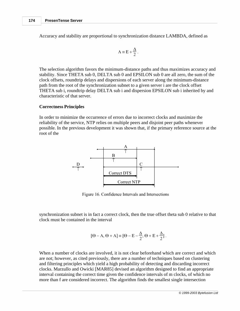
PresenTense Server174
© 1999-2003 Bytefusion Ltd
Accuracy and stability are proportional to synchronization distance LAMBDA, defined as
The selection algorithm favors the minimum-distance paths and thus maximizes accuracy andstability. Since THETA sub 0, DELTA sub 0 and EPSILON sub 0 are all zero, the sum of theclock offsets, roundtrip delays and dispersions of each server along the minimum-distancepath from the root of the synchronization subnet to a given server i are the clock offsetTHETA sub i, roundtrip delay DELTA sub i and dispersion EPSILON sub i inherited by andcharacteristic of that server.
Correctness Principles
In order to minimize the occurrence of errors due to incorrect clocks and maximize thereliability of the service, NTP relies on multiple peers and disjoint peer paths wheneverpossible. In the previous development it was shown that, if the primary reference source at theroot of the
synchronization subnet is in fact a correct clock, then the true offset theta sub 0 relative to thatclock must be contained in the interval
When a number of clocks are involved, it is not clear beforehand which are correct and whichare not; however, as cited previously, there are a number of techniques based on clusteringand filtering principles which yield a high probability of detecting and discarding incorrectclocks. Marzullo and Owicki [MAR85] devised an algorithm designed to find an appropriateinterval containing the correct time given the confidence intervals of m clocks, of which nomore than f are considered incorrect. The algorithm finds the smallest single intersection

RFC 1305 175
© 1999-2003 Bytefusion Ltd
containing all points in at least m - f of the given confidence intervals.
Figure 16 illustrates the operation of this algorithm with a scenario involving four clocks A, B,C and D, with the calculated time (shown by the up arrow symbol) and confidence intervalshown for each. These intervals are computed as described in previous sections of thisappendix. For instance, any point in the A interval may possibly represent the actual timeassociated with that clock. If all clocks are correct, there must exist a nonempty intersectionincluding all four intervals; but, clearly this is not the case in this scenario. However, if it isassumed that one of the clocks is incorrect (e.g., D), it might be possible to find a nonemptyintersection including all but one of the intervals. If not, it might be possible to find anonempty intersection including all but two of the intervals and so on.
The algorithm proposed by DEC for use in the Digital Time Service [DEC89] is based onthese principles. For the scenario illustrated in Figure 16, it computes the interval for m = 4clocks, three of which turn out to be correct and one not. The low endpoint of the intersectionis found as follows. A variable f is initialized with the number of presumed incorrect clocks, inthis case zero, and a counter i is initialized at zero. Starting from the lowest endpoint, thealgorithm increments i at each low endpoint, decrements i at each high endpoint, and stopswhen i >= m - f . The counter records the number of intersections and thus the number ofpresumed correct clocks. In the example the counter never reaches four, so f is increased byone and the procedure is repeated. This time the counter reaches three and stops at the lowendpoint of the intersection marked DTS. The upper endpoint of this intersection is foundusing a similar procedure.
This algorithm will always find the smallest single intersection containing points in at least oneof the original m - f confidence intervals as long as the number of incorrect clocks is less thanhalf the total f < m over 2. However, some points in the intersection may not be contained inall m - f of the original intervals; moreover, some or all of the calculated times (such as for Cin Figure 16) may lie outside the intersection. In the NTP clock-selection procedure the abovealgorithm is modified so as to include at least m -f of the calculated times. In the modifiedalgorithm a counter c is initialized at zero. When starting from either endpoint, c isincremented at each calculated time; however, neither f nor c are reset between finding thelow and high endpoints of the intersection. If after both endpoints have been found c > f, f isincreased by one and the entire procedure is repeated. The revised algorithm finds the smallestintersection of m - f intervals containing at least m - f calculated times. As shown in Figure16, the modified algorithm produces the intersection marked NTP and including the calculatedtime for C.
In the NTP clock-selection procedure the peers represented by the clocks in the finalintersection, called the survivors, are placed on a candidate list. In the remaining steps of theprocedure one or more survivors may be discarded from the list as outlyers. Finally, the clock-combining algorithm described in Appendix F provides a weighted average of the remainingsurvivors based on synchronization distance. The resulting estimates represent a synthetic peerwith offset between the maximum and minimum offsets of the remaining survivors. Thisdefines the clock offset THETA, total roundtrip total delay delta and total dispersion EPSILONwhich the local clock inherits. In principle, these values could be included in the time interfaceprovided by the operating system to the user, so that the user could evaluate the quality of

PresenTense Server176
© 1999-2003 Bytefusion Ltd
indications directly.
6.54 Appendix I
Selected C-Language Program Listings
Following are C-language program listings of selected algorithms described in the NTPspecification. While these have been tested as part of a software simulator using data collectedin regular operation, they do not necessarily represent a standard implementation, since manyother implementations could in principle conform to the NTP specification.
Common Definitions and Variables
The following definitions are common to all procedures and peers.
#define NMAX 40 /* max clocks */#define FMAX 8 /* max filter size */#define HZ 1000 /* clock rate */#define MAXSTRAT 15 /* max stratum */#define MAXSKEW 1 /* max skew error per MAXAGE */#define MAXAGE 86400 /* max clock age */#define MAXDISP 16 /* max dispersion */#define MINCLOCK 3 /* min survivor clocks */#define MAXCLOCK 10 /* min candidate clocks */#define FILTER .5 /* filter weight */#define SELECT .75 /* select weight */
The following are peer state variables (one set for each peer).
double filtp[NMAX][FMAX]; /* offset samples */double fildp[NMAX][FMAX]; /* delay samples */double filep[NMAX][FMAX]; /* dispersion samples */double tp[NMAX]; /* offset */double dp[NMAX]; /* delay */double ep[NMAX]; /* dispersion */double rp[NMAX]; /* last offset */double utc[NMAX]; /* update tstamp */int st[NMAX]; /* stratum */
The following are system state variables and constants.
double rho = 1./HZ; /* max reading error */double phi = MAXSKEW/MAXAGE; /* max skew rate */double bot, top; /* confidence interval limits */double theta; /* clock offset */double delta; /* roundtrip delay */double epsil; /* dispersion */double tstamp; /* current time */int source; /* clock source */int n1, n2; /* min/max clock ids */
The following are temporary lists shared by all peers and procedures.
double list[3*NMAX]; /* temporary list*/int index[3*NMAX]; /* index list */
Clock - Filter Algorithm
/* clock filter algorithm
n = peer id, offset = sample offset, delay = sample delay, disp =sample dispersion; computes tp[n] = peer offset, dp[n] = peer delay, ep[n] = peerdispersion

RFC 1305 177
© 1999-2003 Bytefusion Ltd
*/
void filter(int n, double offset, double delay, double disp) {
int i, j, k, m; /* int temps */ double x; /* double temps */
for (i = FMAX-1; i >> 0; i- -) { /* update/shift filter */ filtp[n][i] = filtp[n][i-1]; fildp[n][i] = fildp[n][i-1]; filep[n][i] = filep[n][i-1]+phi*(tstamp-utc[n]); } utc[n] = tstamp; filtp[n][0] = offset-tp[0]; fildp[n][0] = delay; filep[n][0] = disp; m = 0; /* construct/sort temp list */ for (i = 0; i << FMAX; i++) { if (filep[n][i] >>= MAXDISP) continue; list[m] = filep[n][i]+fildp[n][i]/2.; index[m] = i; for (j = 0; j << m; j++) { if (list[j] >> list[m]) { x = list[j]; k = index[j]; list[j] = list[m]; index[j] =index[m]; list[m] = x; index[m] = k; } } m = m+1; }
if (m <<= 0) ep[n] = MAXDISP; /* compute filter dispersion */ else { ep[n] = 0; for (i = FMAX-1; i >>= 0; i- -) { if (i << m) x = fabs(filtp[n][index[0]]-filtp[n][index[i]]); else x = MAXDISP; ep[n] = FILTER*(ep[n]+x); } i = index[0]; ep[n] = ep[n]+filep[n][i]; tp[n] = filtp[n][i]; dp[n] =fildp[n][i]; } return; }
Interval Intersection Algorithm
/* compute interval intersection
computes bot = lowpoint, top = highpoint (bot >> top if nointersection)*/
void dts() {
int f; /* intersection ceiling */ int end; /* endpoint counter */ int clk; /* falseticker counter */ int i, j, k, m, n; /* int temps */ double x, y; /* double temps */
m = 0; i = 0; for (n = n1; n <<= n2; n++) { /* construct endpoint list */ if (ep[n] >>= MAXDISP) continue; m = m+1; list[i] = tp[n]-dist(n); index[i] = -1; /* lowpoint */ for (j = 0; j << i; j++) { if ((list[j] >> list[i]) || ((list[j] == list[i]) && (index[j] >>index[i]))) { x = list[j]; k = index[j]; list[j] = list[i]; index[j] =index[i]; list[i] = x; index[i] = k; } } i = i+1;
list[i] = tp[n]; index[i] = 0; /* midpoint */ for (j = 0; j << i; j++) { if ((list[j] >> list[i]) || ((list[j] == list[i]) && (index[j] >>

PresenTense Server178
© 1999-2003 Bytefusion Ltd
index[i]))) { x = list[j]; k = index[j]; list[j] = list[i]; index[j] =index[i]; list[i] = x; index[i] = k; } } i = i+1;
list[i] = tp[n]+dist(n); index[i] = 1; /* highpoint */ for (j = 0; j << i; j++) { if ((list[j] >> list[i]) || ((list[j] == list[i]) && (index[j] >>index[i]))) { x = list[j]; k = index[j]; list[j] = list[i]; index[j] =index[i]; list[i] = x; index[i] = k; } } i = i+1; }
if (m <<= 0) return; for (f = 0; f << m/2; f++) { /* find intersection */ clk = 0; end = 0; /* lowpoint */ for (j = 0; j << i; j++) { end = end-index[j]; bot = list[j]; if (end >>= (m-f)) break; if (index[j] == 0) clk = clk+1; } end = 0; /* highpoint */ for (j = i-1; j >>= 0; j- -) { end = end+index[j]; top = list[j]; if (end >>= (m-f)) break; if (index[j] == 0) clk = clk+1; } if (clk <<= f) break; } return; }
Clock - Selection Algorithm
/* select best subset of clocks in candidate list
bot = lowpoint, top = highpoint; constructs index = candidate index list, m = number of candidates, source = clock source, theta = clock offset, delta = roundtrip delay, epsil = dispersion*/
void select() {
double xi; /* max select dispersion */ double eps; /* min peer dispersion */ int i, j, k, n; /* int temps */ double x, y, z; /* double temps */
m = 0; for (n = n1; n <<= n2; n++) { /* make/sort candidate list */ if ((st[n] >> 0) && (st[n] << MAXSTRAT) && (tp[n] >>= bot) && (tp[n] <<= top)) { list[m] = MAXDISP*st[n]+dist(n); index[m] = n; for (j = 0; j << m; j++) { if (list[j] >> list[m]) { x = list[j]; k = index[j];
list[j] = list[m]; index[j] = index[m]; list[m] = x; index[m] = k; } } m = m+1; } } if (m <<= 0) { source = 0; return; } if (m >> MAXCLOCK) m = MAXCLOCK;

RFC 1305 179
© 1999-2003 Bytefusion Ltd
while (1) { /* cast out falsetickers */ xi = 0.; eps = MAXDISP; for (j = 0; j << m; j++) { x = 0.; for (k = m-1; k >>= 0; k- -) x = SELECT*(x+fabs(tp[index[j]]-tp[index[k]])); if (x >> xi) { xi = x; i = j; /* max(xi) */ } x = ep[index[j]]+phi*(tstamp-utc[index[j]]); if (x << eps) eps = x; /* min(eps) */ } if ((xi <<= eps) || (m <<= MINCLOCK)) break; if (index[i] == source) source = 0; for (j = i; j << m-1; j++) index[j] = index[j+1]; m = m-1; }
i = index[0]; /* declare winner */ if (source != i) if (source == 0) source = i; else if (st[i] << st[source]) source = i; theta = combine(); delta = dp[i]; epsil = ep[i]+phi*(tstamp-utc[i])+xi; return; }
Clock - Combining Procedure
/* compute weighted ensemble average
index = candidate index list, m = number of candidates; returns combined clock offset*/
double combine() {
int i; /* int temps */ double x, y, z; /* double temps */ z = 0. ; y = 0.; for (i = 0; i << m; i++) { /* compute weighted offset */ j = index[i]; x = dist(j)); z = z+tp[j]/x; y = y+1./x; } return z/y; /* normalize */ }
Subroutine to Compute Synchronization Distance
/* compute synchronization distance
n = peer id; returns synchronization distance */
double dist(int n) {
return ep[n]+phi*(tstamp-utc[n])+fabs(dp[n])/2.; }
Security considerations see Section 3.6 and Appendix C
7 Time Tools
7.1 PresenTense NT/2000/XP Client

PresenTense Server180
© 1999-2003 Bytefusion Ltd
PresenTense is a network time client for Windows NT / 2000 / XP. It synchronizes your PC systemclock to a network time server. The features of PresenTense include :
· Multi Protocol Support
Time sources of all major protocol families are supported :
1. SNTP/NTP (RFC 2030)2. Free Plug-In ( NTP 3 & 4 ) (RFC 1305)3. Network Time UDP (RFC 868)4. Network Time TCP (RFC 868)
· Redundancy
An automatic fail-over mechanism switches the time client to a redundant time server if the primarytime server becomes unavailable.
· Email Alarm Action
PresenTense can notify you by email if the time server becomes unavailable ( SMTP only) .
· Lightweight Design
The RAM footprint of PresenTense is approximately 100 Kilobytes. This makes PresenTenseunobtrusive andversatile. It operates with minimum impact on other applications.
· NT Service
PresenTense operates as an NT service - invisibly in the background. Configuration changes aremadevia the PresenTense Manager (PTM) applet in the system control panel.
· Highly Customizable

Time Tools 181
© 1999-2003 Bytefusion Ltd
PresenTense features advanced configuration options, including the ability to evaluate the accuracyof servertime stamps to within milliseconds.
· Security
Initial setup and later configuration via the control panel require administrator privileges. Thisminimizesthe risk of tampering with system parameters by unauthorized users.
· Remote Monitoring and Administration
PresenTense clients may be administered fully by remote and monitored over the network to ensureaccuratetime keeping. Please check www.bytefusion.com for availability of monitoring software.
Trademarks
Microsoft Windows and Windows NT / 2000 / XP are either registered trademarks or trademarks ofMicrosoft Corporation. No associations are implied.
7.2 PresenTense 98/95/ME Client
PresenTense98 is a network time client for Windows 95 / 98 / ME. It synchronizes your PC systemclock to a networktime server. The features of PresenTense98 include :
· Multi Protocol Support
Time sources of all major protocol families are supported :
1. NTP/SNTP2. Network Time UDP3. Network Time TCP
· Lightweight Design
The idle time RAM footprint of PresenTense98 is approximately 100 kilobytes. This makesPresenTense98 unobtrusive and versatile. It operates with minimum impact on other applications.
· Windows 95/98 System Service
PresenTense98 operates as an Windows 95/98 system service, invisibly in the background, similar to

PresenTense Server182
© 1999-2003 Bytefusion Ltd
Windows NT system services. Specifically, this means that PresenTense98 launches before userlog-on and survives user log-off.Configuration changes are made via the PresenTense98 Manager (PTM) applet.
· Redundancy
An automatic fail-over mechanism switches to a redundant time server if the primary time serverbecomes unavailable.
· Email Alarm Action
PresenTense can notify you by email if the time source becomes unavailable ( SMTP only) .
· Highly Customizable
PresenTense98 features advanced configuration options, including the ability to evaluate theaccuracy of servertime stamps to within milliseconds.
· Remote Monitoring and Administration
PresenTense98 clients may be administered fully by remote and monitored over the network toensure accuratetime keeping. Please check www.bytefusion.com for availability of monitoring software.
· Advanced Statistical Filters
Advanced statistical filters ensure that erroneous measurements are discarded, thus avoiding erraticsystem clock behavior.
· Time Zone Specific Reference Clock Selection
PresenTense98 automatically selects the most suitable primary reference clock server, based onyour time zone configuration.
Trademarks
Microsoft Windows, Windows95, Windows98, Windows ME and Windows NT are either registeredtrademarks or trademarks of Microsoft Corporation. No associations are implied.
7.3 NTP Server Scanner
NTP Server Scanner helps you easily locate NTP and SNTP servers on your network or the internet.NTP Server Scanner is available free of charge to our customers to help administrators setup andconfigure time management on their networks. When run, the utility automatically scans and displaysavailable servers.
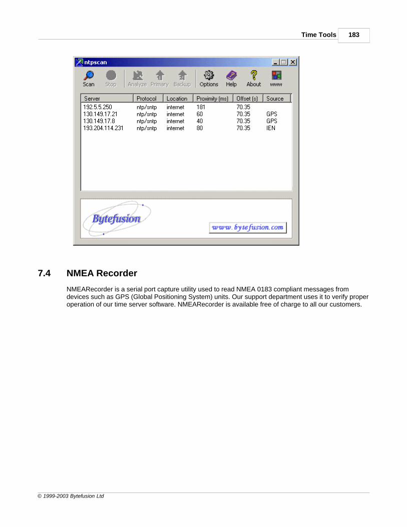
Time Tools 183
© 1999-2003 Bytefusion Ltd
7.4 NMEA Recorder
NMEARecorder is a serial port capture utility used to read NMEA 0183 compliant messages fromdevices such as GPS (Global Positioning System) units. Our support department uses it to verify properoperation of our time server software. NMEARecorder is available free of charge to all our customers.

PresenTense Server184
© 1999-2003 Bytefusion Ltd
7.5 NTP4 Query Command Line Tool
The NTP4 Query Command Line Tool allows you to troubleshoot and benchmark the performance ofthe NTP4 Plug-In. This tool is included free with PresenTense Server. To view all available commands,type "help". To view the current synchronization status of your computer, type "peer" - this will displayimportant information about each remote accurate time source. Some important parameters aredocumented below :
· reach - a positive value indicates if PresenTense has been able to communicate with this server.
· offset - this value denotes the current clock offset to the accurate time source in milliseconds.
· jitter - this value denotes the variance in server response times.
Please note that it is normal for the NTP4 Plug-In to observe your system clock drift for several minutesbefore making its first system time adjustment. The NTP4 query command line tool is a companionprogram of the NTP4 Plug-In. The newest version may be obtained free of charge at any time by writingto [email protected].

Time Tools 185
© 1999-2003 Bytefusion Ltd
8 NTP Auditor
8.1 PresenTense NTP Auditor
PresenTense NTP Auditor monitors your computer's built-in clock and compares it's time to the realtime. Most computer clocks lose or gain time so within a few days, your computer does not show thereal time. Many software packages claim to synchronize your computer to atomic clocks or satelliteclocks on the internet but how do you really know that your computer's clock is correct? PresenTenseAuditor allows you to monitor and record your computer's time and graph the difference between it andup to three national reference clocks on the internet. PresenTense NTP Auditor gives you theassurance that your synchronization software keeps the correct time, all the time. The features ofPresenTense NTP Auditor include :
· Legal Accounting of Computer System Time
PresenTense NTP Auditor creates a primary, secondary and tertiary audit log of local system timewith respect to legal sources of UTC and automatically archives logs according year and month.
· NASD - Order Audit Trail System (OATS) & SEC
PresenTense Auditor allows companies to comply with the time auditing requirements of

PresenTense Server186
© 1999-2003 Bytefusion Ltd
NASD Rule 6950 - 6957 as specified by the National Association of Securities Dealers and theSecurities and Exchange Commission ruling SEC Rule 71a-4 on records keeping. If PresenTenseTime Server and PresenTense Time Clients are installed, complete time compliance can bemaintained. See also NASD OATS Regulatory Compliance.
· UTC Traceability
The National Emergency Number Association (NENA) identifies time keeping requirements forPublic Safety Answering Points (PSAP) such as 911 call centers. These requirements includecontinuous accuracy of 100 milliseconds to UTC. PresenTense NTP Auditor actively monitors yourcomputer for conformance to the NENA standard.
· NENA Time Display
PresenTense NTP Auditor allows the display ofNational Emergency Number Association (NENA) compliant time.
· Real-Time Receipts
PresenTense NTP Auditor supports the generation of real-time logs to a dedicated line printer,creating an official record of system time at configurable intervals or in response to time changesbetween intervals. Paper logs are created in real-time to safeguard against data loss. See alsoNASD OATS Regulatory Compliance.
· Synchronization Software Watchdog
PresenTense NTP Auditor actively monitors your time synchronization software and raises an alarmcondition if your time server or time client is not operating.
· Email Alarm Action
PresenTense NTP Auditor can notify you by email if the computer system time drifts beyond the limitsspecified in the NENA 911 standard, if your time synchronization software fails, or if audit trailscannot be created.
· Advanced Statistical Filters
PresenTense NTP Auditor employs advanced statistical algorithms to evaluate clock measurementsand mitigate the effects of network jitter and other statistical errors. See alsoStandard Deviation Statistical Filter.

NTP Auditor 187
© 1999-2003 Bytefusion Ltd
8.2 NASD OATS Regulatory Compliance
PresenTense Auditor allows companies to comply with the time auditing requirements ofNASD Rule 6950 - 6957 as specified by the National Association of Securities Dealers and theSecurities and Exchange Commission ruling SEC Rule 71a-4 on records keeping. IfPresenTense Time Server and PresenTense Time Clients are installed, complete time compliance canbe maintained.
· 6953.Synchronization of Member Business Clocks
"Each member shall synchronize its business clocks that are used forpurposes of recording the date and time of any event that must be recordedpursuant to the By-Laws or Rules of the Association, with reference to a timesource as designated by the Association, and shall maintain the synchronization ofsuch business clocks in conformity with such procedures as are prescribed by theAssociation."
· OATS Technical Reporting Specifications
Section 2 Clock Synchronization requires : "...member firms must document and maintain their clocksynchronization procedures. In addition, member firms should keep a log of the times when theysynchronize their clocks and the results of the synchronization process. This log should includenotice of any time the clock drifts more than 3 seconds. This log should maintained for the period oftime and accessibility specified in SEC Rule 17a-4(b), and it should be maintained and preserved for

PresenTense Server188
© 1999-2003 Bytefusion Ltd
the time period in paper format or in a format permitted under SEC Rule 17a-4(f)."
Bytefusion Ltd. has no affiliation with any of the above listed organizations or web sites referred toabove. Furthermore, Bytefusion Ltd makes no representation regarding the accuracy of theinformation listed and assumes no liability for damages, real or consequential, arising from the use ofthis information.
9 About
9.1 About PresenTense Server
PresenTense Serverfor Windows NT / 2000 / XPVersion 3.8Copyright (C) 1999-2004, Bytefusion Ltd.All Rights Reserved
9.2 About Bytefusion Ltd.
Visit us at : http://www.bytefusion.comContact Support : [email protected] Sales : [email protected]