table of contents · schutzvermerk gezeichnet: 30.09.08 pz/scb ersatz für: ktr-n vom 04.11.05 iso...
TRANSCRIPT
BoWex® SD, SD-D, SD1 and SD2 Operating/Assembly instructions
KTR-N Sheet: Edition:
40111 EN 1 of 19 6
Please observe protection note ISO 16016.
Drawn: 2021-01-14 Pz Replacing: KTR-N dated 2008-09-30
Verified: 2021-01-21 Pz Replaced by:
BoWex®
Non-failsafe curved-tooth gear couplings type SD, SD-D, SD1, SD2 and their combinations
BoWex® SD, SD-D, SD1 and SD2 Operating/Assembly instructions
KTR-N Sheet: Edition:
40111 EN 2 of 19 6
Please observe protection note ISO 16016.
Drawn: 2021-01-14 Pz Replacing: KTR-N dated 2008-09-30
Verified: 2021-01-21 Pz Replaced by:
The BoWex® curved-tooth gear coupling is a flexible shaft connection. It is able to compensate for shaft misalignment, for example caused by manufacturing inaccuracies, thermal expansion, etc.
1 Technical data 3
2 Advice 9
2.1 General advice 9 2.2 Safety and advice symbols 9 2.3 General hazard warnings 9 2.4 Intended use 10 2.5 Coupling selection 10 2.6 Reference to EC Machinery Directive 2006/42/EC 10
3 Storage, transport and packaging 10
3.1 Storage 10 3.2 Transport and packaging 11
4 Assembly 11
4.1 Components of the couplings 11 4.2 Advice for finish bore 12 4.3 Advice on shifting force 12 4.4 Assembly of the hubs 13 4.5 Displacements - alignment of the couplings 13 4.6 Assembly of the slip ring for BoWex® SD1 and SD2 14 4.7 Maintenance intervals for BoWex® SD1 and SD2 15 4.8 Assembly of the shiftable linkage for BoWex® SD1 and SD2 16
5 Start-up 17
6 Breakdowns, causes and elimination 18
7 Disposal 19
8 Spares inventory, customer service addresses 19
Table of contents
BoWex® SD, SD-D, SD1 and SD2 Operating/Assembly instructions
KTR-N Sheet: Edition:
40111 EN 3 of 19 6
Please observe protection note ISO 16016.
Drawn: 2021-01-14 Pz Replacing: KTR-N dated 2008-09-30
Verified: 2021-01-21 Pz Replaced by:
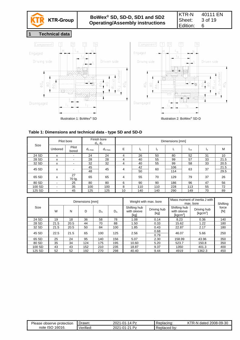
Illustration 1: BoWex® SD Illustration 2: BoWex® SD-D
Table 1: Dimensions and technical data - type SD and SD-D
Size
Pilot bore Finish bore
d1, d2 Dimensions [mm]
Unbored Pilot
bored d1 max. d2 max. E l1 l2 L LH l3 M
24 SD x - 24 24 4 26 50 80 52 31 10
28 SD x - 28 28 4 40 55 99 57 33 21.5
32 SD x - 32 32 4 40 55 99 58 33 20.5
45 SD x - 45
45 4 42
60 106
63 37 21.5
48 50 114 29.5
65 SD x 27
70 lg. 65 65 4 55 70 129 79 37 26
80 SD - 25 80 80 6 90 90 186 96 47 56
100 SD - 35 100 100 8 110 110 228 113 55 72
125 SD - 45 125 125 10 140 140 290 149 70 89
Size
Dimensions [mm] Weight with max. bore Mass moment of inertia J with
max. bore Shifting force [N] W N D DH DA
Shifting hub with sleeve
[kg]
Driving hub [kg]
Shifting hub with sleeve
[kgcm2]
Driving hub [kgcm2]
24 SD 19 18 36 58 78 1.08 0.14 8.23 0.36 140
28 SD 21.5 20.5 44 70 88 1.50 0.33 15.62 1.22 180
32 SD 21.5 20.5 50 84 100 1.85 0.43 22.87 2.17 180
45 SD 22.5 21.5 65 100 125 2.56 0.68
46.07 5.66 250 0.79
65 SD 25 24 95 140 156 5.07 2.30 158.99 43.96 350
80 SD 35 34 124 175 195 10.60 5.20 523.7 150.8 350
100 SD 43 43 152 210 235 18.87 9.37 1350 401.3 400
125 SD 52 52 192 270 298 40.40 9.44 4919 1362.3 450
1 Technical data
BoWex® SD, SD-D, SD1 and SD2 Operating/Assembly instructions
KTR-N Sheet: Edition:
40111 EN 4 of 19 6
Please observe protection note ISO 16016.
Drawn: 2021-01-14 Pz Replacing: KTR-N dated 2008-09-30
Verified: 2021-01-21 Pz Replaced by:
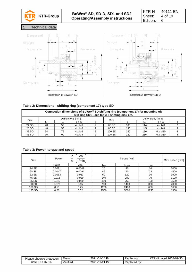
Illustration 1: BoWex® SD Illustration 2: BoWex® SD-D
Table 2: Dimensions - shifting ring (component 17) type SD
Connection dimensions of BoWex® SD shifting ring (component 17) for mounting of: slip ring SD1 - see table 5 shifting disk etc.
Size Dimensions [mm]
Size Dimensions [mm]
L1 L2 z x G s L1 L2 z x G s
24 SD 48 58 4 x M6 2 65 SD 100 114 4 x M8 2
28 SD 48 58 4 x M6 2 80 SD 130 145 4 x M8 3
32 SD 64 75 4 x M6 2 100 SD 180 196 6 x M10 4
45 SD 75 90 4 x M8 2 125 SD 220 236 6 x M10 4
Table 3: Power, torque and speed
Size Power
1/min
kW
n
P
Torque [Nm] Max. speed [rpm]
Rated Max. TKN TK max TKW
24 SD 0.0021 0.0042 20 40 10 5000
28 SD 0.0047 0.0094 45 90 23 4400
32 SD 0.0063 0.013 60 120 30 3900
45 SD 0.015 0.029 140 280 70 3100
65 SD 0.040 0.080 380 760 190 2500
80 SD 0.073 0.15 700 1400 350 2000
100 SD 0.13 0.25 1200 2400 600 1650
125 SD 0.26 0.52 2500 5000 1250 1300
1 Technical data
BoWex® SD, SD-D, SD1 and SD2 Operating/Assembly instructions
KTR-N Sheet: Edition:
40111 EN 5 of 19 6
Please observe protection note ISO 16016.
Drawn: 2021-01-14 Pz Replacing: KTR-N dated 2008-09-30
Verified: 2021-01-21 Pz Replaced by:
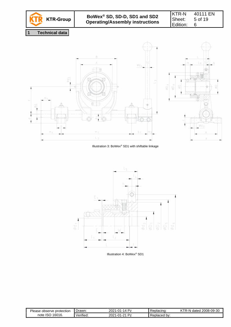
Illustration 3: BoWex® SD1 with shiftable linkage
Illustration 4: BoWex® SD1
1 Technical data
BoWex® SD, SD-D, SD1 and SD2 Operating/Assembly instructions
KTR-N Sheet: Edition:
40111 EN 6 of 19 6
Please observe protection note ISO 16016.
Drawn: 2021-01-14 Pz Replacing: KTR-N dated 2008-09-30
Verified: 2021-01-21 Pz Replaced by:
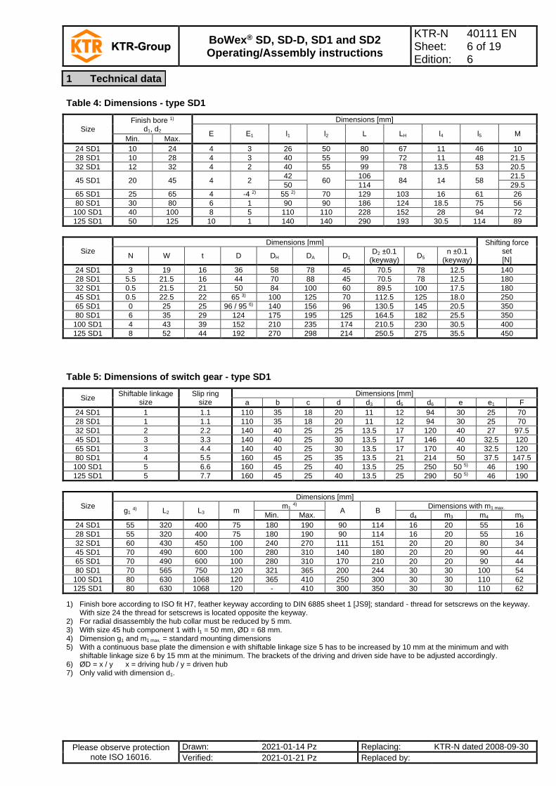
Table 4: Dimensions - type SD1
Size
Finish bore 1) d1, d2
Dimensions [mm]
E E1 l1 l2 L LH l4 l5 M Min. Max.
24 SD1 10 24 4 3 26 50 80 67 11 46 10
28 SD1 10 28 4 3 40 55 99 72 11 48 21.5
32 SD1 12 32 4 2 40 55 99 78 13.5 53 20.5
45 SD1 20 45 4 2 42
60 106
84 14 58 21.5
50 114 29.5
65 SD1 25 65 4 -4 2) 55 2) 70 129 103 16 61 26
80 SD1 30 80 6 1 90 90 186 124 18.5 75 56
100 SD1 40 100 8 5 110 110 228 152 28 94 72
125 SD1 50 125 10 1 140 140 290 193 30.5 114 89
Size
Dimensions [mm] Shifting force set [N]
N W t D DH DA D1 D2 ±0.1
(keyway) D5
n ±0.1 (keyway)
24 SD1 3 19 16 36 58 78 45 70.5 78 12.5 140
28 SD1 5.5 21.5 16 44 70 88 45 70.5 78 12.5 180
32 SD1 0.5 21.5 21 50 84 100 60 89.5 100 17.5 180
45 SD1 0.5 22.5 22 65 3) 100 125 70 112.5 125 18.0 250
65 SD1 0 25 25 96 / 95 6) 140 156 96 130.5 145 20.5 350
80 SD1 6 35 29 124 175 195 125 164.5 182 25.5 350
100 SD1 4 43 39 152 210 235 174 210.5 230 30.5 400
125 SD1 8 52 44 192 270 298 214 250.5 275 35.5 450
Table 5: Dimensions of switch gear - type SD1
Size Shiftable linkage
size Slip ring
size
Dimensions [mm]
a b c d d3 d5 d6 e e1 F
24 SD1 1 1.1 110 35 18 20 11 12 94 30 25 70
28 SD1 1 1.1 110 35 18 20 11 12 94 30 25 70
32 SD1 2 2.2 140 40 25 25 13.5 17 120 40 27 97.5
45 SD1 3 3.3 140 40 25 30 13.5 17 146 40 32.5 120
65 SD1 3 4.4 140 40 25 30 13.5 17 170 40 32.5 120
80 SD1 4 5.5 160 45 25 35 13.5 21 214 50 37.5 147.5
100 SD1 5 6.6 160 45 25 40 13.5 25 250 50 5) 46 190
125 SD1 5 7.7 160 45 25 40 13.5 25 290 50 5) 46 190
Size
Dimensions [mm]
g1 4) L2 L3 m
m1 4)
A B Dimensions with m1 max.
Min. Max. d4 m3 m4 m5
24 SD1 55 320 400 75 180 190 90 114 16 20 55 16
28 SD1 55 320 400 75 180 190 90 114 16 20 55 16
32 SD1 60 430 450 100 240 270 111 151 20 20 80 34
45 SD1 70 490 600 100 280 310 140 180 20 20 90 44
65 SD1 70 490 600 100 280 310 170 210 20 20 90 44
80 SD1 70 565 750 120 321 365 200 244 30 30 100 54
100 SD1 80 630 1068 120 365 410 250 300 30 30 110 62
125 SD1 80 630 1068 120 - 410 300 350 30 30 110 62
1) Finish bore according to ISO fit H7, feather keyway according to DIN 6885 sheet 1 [JS9]; standard - thread for setscrews on the keyway. With size 24 the thread for setscrews is located opposite the keyway.
2) For radial disassembly the hub collar must be reduced by 5 mm. 3) With size 45 hub component 1 with l1 = 50 mm, ØD = 68 mm. 4) Dimension g1 and m1 max. = standard mounting dimensions 5) With a continuous base plate the dimension e with shiftable linkage size 5 has to be increased by 10 mm at the minimum and with
shiftable linkage size 6 by 15 mm at the minimum. The brackets of the driving and driven side have to be adjusted accordingly. 6) ØD = x / y x = driving hub / y = driven hub 7) Only valid with dimension d1.
1 Technical data
BoWex® SD, SD-D, SD1 and SD2 Operating/Assembly instructions
KTR-N Sheet: Edition:
40111 EN 7 of 19 6
Please observe protection note ISO 16016.
Drawn: 2021-01-14 Pz Replacing: KTR-N dated 2008-09-30
Verified: 2021-01-21 Pz Replaced by:
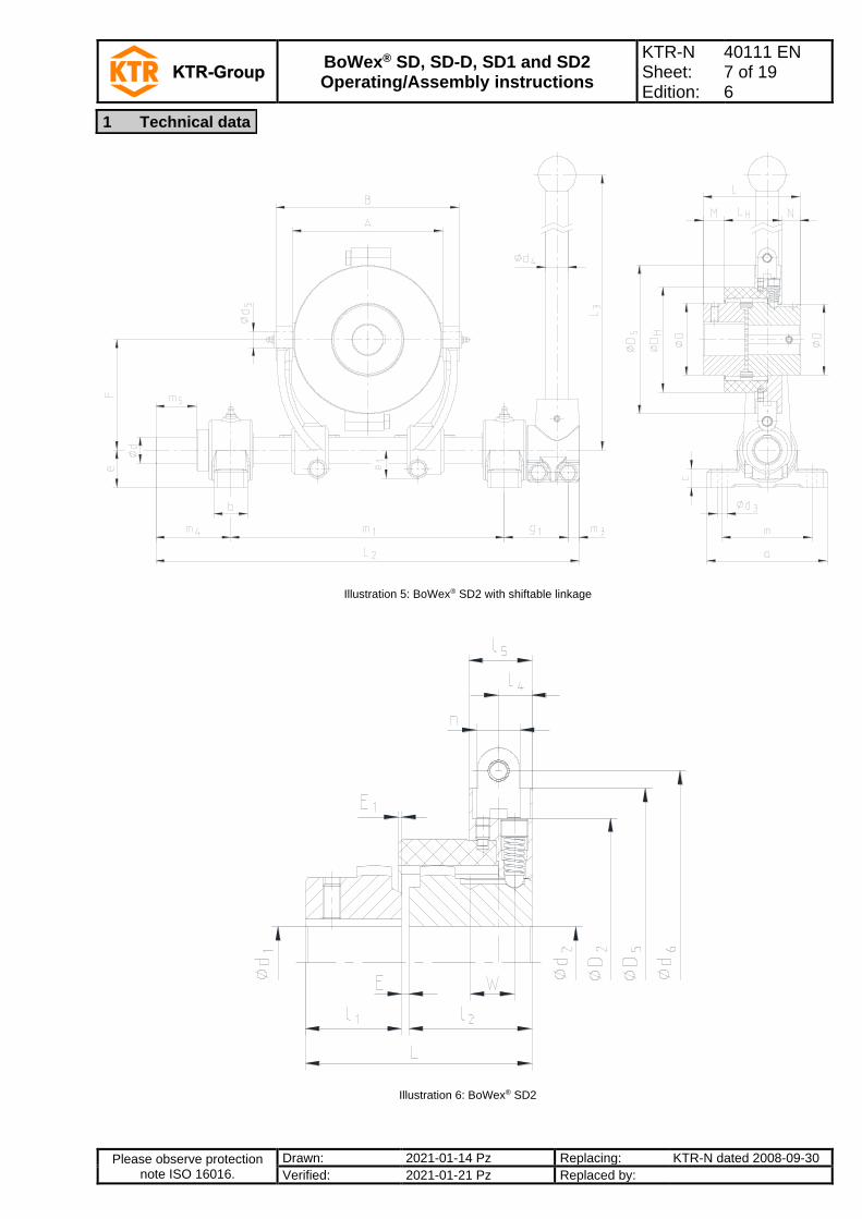
Illustration 5: BoWex® SD2 with shiftable linkage
Illustration 6: BoWex® SD2
1 Technical data

BoWex® SD, SD-D, SD1 and SD2 Operating/Assembly instructions
KTR-N Sheet: Edition:
40111 EN 8 of 19 6
Please observe protection note ISO 16016.
Drawn: 2021-01-14 Pz Replacing: KTR-N dated 2008-09-30
Verified: 2021-01-21 Pz Replaced by:
Table 6: Dimensions - type SD2
Size
Finish bore 1) d1, d2
Dimensions [mm]
E E1 l1 l2 L LH l4 l5 Min. Max.
24 SD2 10 24 4 3 26 50 80 51 9.5 30
28 SD2 10 28 4 3 40 55 99 56 16 32
32 SD2 12 32 4 2 40 55 99 57 16 32
45 SD2 20 45
4 2 42
60 106
62 16 36 48 7) 50 114
65 SD2 25 65 4 -4 2) 55 2) 70 129 78 18 36
80 SD2 30 80 6 1 90 90 186 95 23 46
100 SD2 40 100 8 5 110 110 228 113 28 55
125 SD2 50 125 10 1 140 140 290 149 30 70
Size
Dimensions [mm] Shifting force set
[N] M N W D DH D2 ±0.1
(keyway) D5
n ±0.1 (keyway)
24 SD2 10 19 19 36 58 70.5 88 12.5 140
28 SD2 21.5 21.5 21.5 44 70 89.5 113 17.5 180
32 SD2 20.5 21.5 21.5 50 84 112.5 136 18 180
45 SD2 21.5
22.5 22.5 65 3) 100 130.5 154 20.5 250 29.5
65 SD2 26 25 25 96 / 95 6) 140 164.5 198 25.5 350
80 SD2 56 35 35 124 175 210.5 250 30.5 350
100 SD2 72 43 43 152 210 250.5 295 35.5 400
125 SD2 89 52 52 192 270 300.5 355 38.5 450
Table 7: Dimensions of shift gear - type SD2
Size Shiftable linkage
size Slip ring
size
Dimensions [mm]
a b c d d3 d5 d6 e e1 F
24 SD2 1 1.1 110 35 18 20 11 12 94 30 25 70
28 SD2 2 2.2 140 40 25 25 13.5 17 120 40 27 97.5
32 SD2 3 3.3 140 40 25 30 13.5 17 146 40 32.5 120
45 SD2 3 4.4 140 40 25 30 13.5 17 170 40 32.5 120
65 SD2 4 5.5 160 45 25 35 13.5 21 214 50 37.5 147.5
80 SD2 5 6.6 160 45 25 40 13.5 25 250 50 5) 46 190
100 SD2 5 7.7 160 45 25 40 13.5 25 290 50 5) 46 190
125 SD2 6 8.8 160 45 25 40 13.5 35 360 50 5) 56 265
Size
Dimensions [mm]
g1 4) L2 L3 m
m1 4)
A B Dimensions with m1 max.
Min. Max. d4 m3 m4 m5
24 SD2 55 320 400 75 180 190 90 114 16 20 55 16
28 SD2 60 430 450 100 240 270 111 151 20 20 80 34
32 SD2 70 490 600 100 280 310 140 180 20 20 90 44
45 SD2 70 490 600 100 280 310 170 210 20 20 90 44
65 SD2 70 565 750 120 321 365 200 244 30 30 100 54
80 SD2 80 630 1068 120 365 410 250 300 30 30 110 62
100 SD2 80 630 1068 120 - 410 300 350 30 30 110 62
125 SD2 80 760 1068 120 - 540 360 420 30 30 110 62
1) Finish bore according to ISO fit H7, feather keyway according to DIN 6885 sheet 1 [JS9]; standard - thread for setscrews on the keyway. With size 24 the thread for setscrews is located opposite the keyway.
2) For radial disassembly the hub collar must be reduced by 5 mm. 3) With size 45 hub component 1 with l1 = 50 mm, ØD = 68 mm. 4) Dimension g1 and m1 max. = standard mounting dimensions 5) With a continuous base plate the dimension e with shiftable linkage size 5 has to be increased by 10 mm at the minimum and with
shiftable linkage size 6 by 15 mm at the minimum. The brackets of the driving and driven side have to be adjusted accordingly. 6) ØD = x / y x = driving hub / y = driven hub 7) Only valid with dimension d1.
1 Technical data
BoWex® SD, SD-D, SD1 and SD2 Operating/Assembly instructions
KTR-N Sheet: Edition:
40111 EN 9 of 19 6
Please observe protection note ISO 16016.
Drawn: 2021-01-14 Pz Replacing: KTR-N dated 2008-09-30
Verified: 2021-01-21 Pz Replaced by:
Please read through these operating/assembly instructions carefully before you start up the coupling. Please pay special attention to the safety instructions! The operating/assembly instructions are part of your product. Please store them carefully and close to the coupling. The copyright for these operating/assembly instructions remains with KTR.
STOP
Warning of personal injury This symbol indicates notes which may contribute to preventing bodily injuries or serious bodily injuries that may result in death.
!
Warning of product damages This symbol indicates notes which may contribute to preventing material or machine damage.
General advice This symbol indicates notes which may contribute to preventing adverse results or conditions.
Warning of hot surfaces
This symbol indicates notes which may contribute to preventing burns with hot surfaces resulting in light to serious bodily injuries.
STOP
With assembly, operation and maintenance of the coupling it has to be made sure that the entire drive train is secured against accidental switch-on. You may be seriously hurt by rotating parts. Please make absolutely sure to read through and observe the following safety indications.
• All operations on and with the coupling have to be performed taking into account "safety first".
• Please make sure to switch off the power pack before you perform your work on the coupling.
• Secure the power pack against accidental switch-on, e. g. by providing warning signs at the place of switch-on or removing the fuse for current supply.
• Do not reach into the operating area of the coupling as long as it is in operation.
• Please secure the coupling against accidental contact. Please provide for the necessary protection devices and covers.
2 Advice
2.1 General advice
2.2 Safety and advice symbols
2.3 General hazard warnings

BoWex® SD, SD-D, SD1 and SD2 Operating/Assembly instructions
KTR-N Sheet: Edition:
40111 EN 10 of 19 6
Please observe protection note ISO 16016.
Drawn: 2021-01-14 Pz Replacing: KTR-N dated 2008-09-30
Verified: 2021-01-21 Pz Replaced by:
You may only assemble, operate and maintain the coupling if you
• have carefully read through the operating/assembly instructions and understood them
• are technically qualified and specifically trained (e. g. safety, environment, logistics)
• are authorized by your company
The coupling may only be used in accordance with the technical data (see chapter 1). Unauthorized modifications on the coupling design are not admissible. We will not assume liability for any damage that may arise. In the interest of further development we reserve the right for technical modifications. The BoWex® described in here corresponds to the technical status at the time of printing of these operating/assembly instructions.
!
For a long-lasting and failure-free operation of the coupling it must be selected according to the selection instructions (according to DIN 740 part 2) for the particular application (see catalogue drive technology „BoWex®“). If the operating conditions (performance, speed, modifications on engine and machine) change, the coupling selection must be reviewed. Please make sure that the technical data regarding torque refer to the sleeve only. The transmittable torque of the shaft-hub-connection must be reviewed by the customer and is subject to his responsibility.
For drives subjected to torsional vibrations (drives with cyclic stress due to torsional vibrations) it is necessary to perform a torsional vibration calculation to ensure a reliable selection. Typical drives subjected to torsional vibrations are e. g. drives with diesel engines, piston pumps, piston compressors etc. If requested, KTR will perform the coupling selection and the torsional vibration calculation.
The couplings supplied by KTR should be considered as components, not machines or partly completed machines according to EC Machinery Directive 2006/42/EC. Consequently KTR does not have to issue a declaration of incorporation. For details about safe assembly, start-up and safe operation refer to the present operating/assembly instructions considering the warnings.
The coupling hubs are supplied in preserved condition and can be stored in a dry and roofed place for 6 - 9 months. The features of the coupling sleeves remain unchanged for up to 5 years with favourable storage conditions.
!
The storage rooms must not include any ozone-generating devices like e. g. fluorescent light sources, mercury-vapour lamps or electrical high-voltage appliances. Humid storage rooms are not suitable. Please make sure that condensation is not generated. The best relative air humidity is less than 65 %.
2 Advice
2.4 Intended use
2.5 Coupling selection
2.6 Reference to EC Machinery Directive 2006/42/EC
3 Storage, transport and packaging
3.1 Storage
BoWex® SD, SD-D, SD1 and SD2 Operating/Assembly instructions
KTR-N Sheet: Edition:
40111 EN 11 of 19 6
Please observe protection note ISO 16016.
Drawn: 2021-01-14 Pz Replacing: KTR-N dated 2008-09-30
Verified: 2021-01-21 Pz Replaced by:
!
In order to avoid any injuries and any kind of damage please always make use of proper transport and lifting equipment.
The couplings are packed differently each depending on size, number and kind of transport. Unless otherwise contractually agreed, packaging will follow the in-house packaging specifications of KTR.
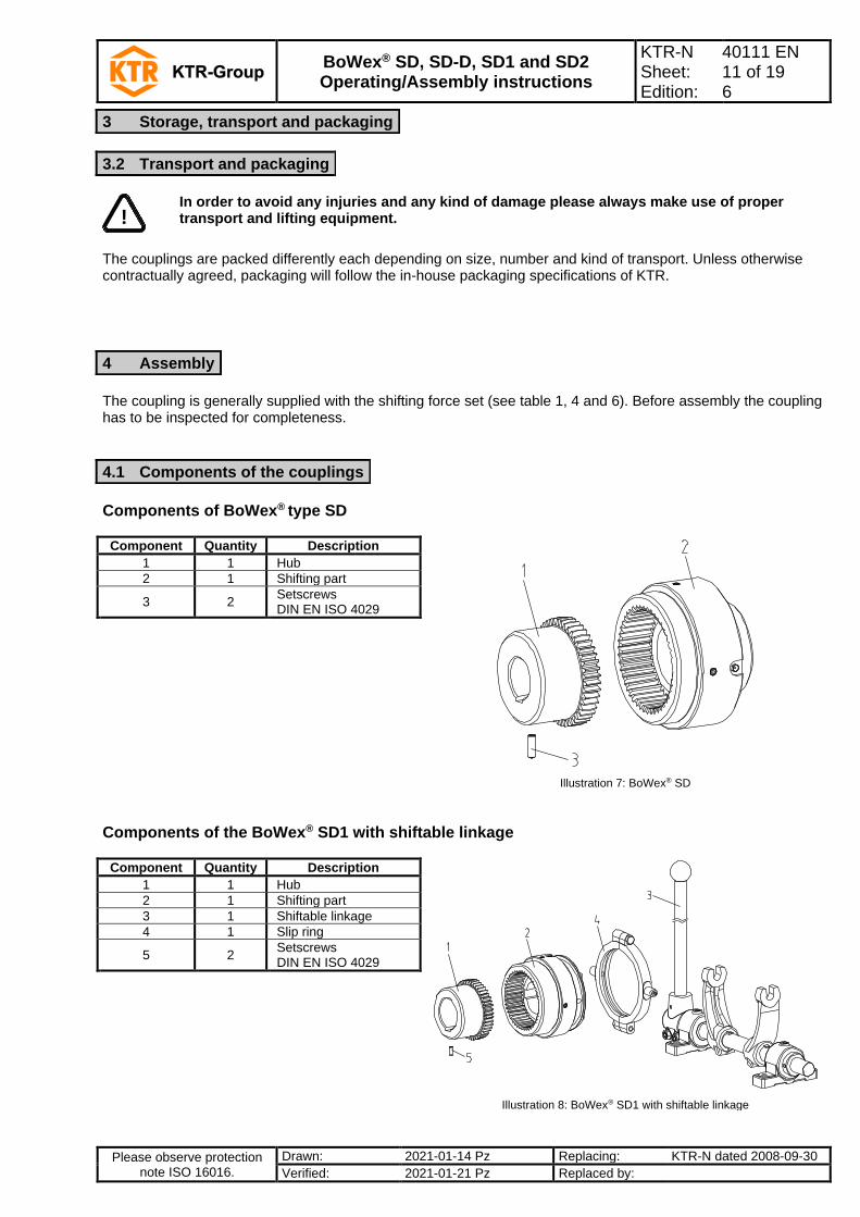
The coupling is generally supplied with the shifting force set (see table 1, 4 and 6). Before assembly the coupling has to be inspected for completeness.
Components of BoWex® type SD
Component Quantity Description
Illustration 7: BoWex® SD
1 1 Hub
2 1 Shifting part
3 2 Setscrews DIN EN ISO 4029
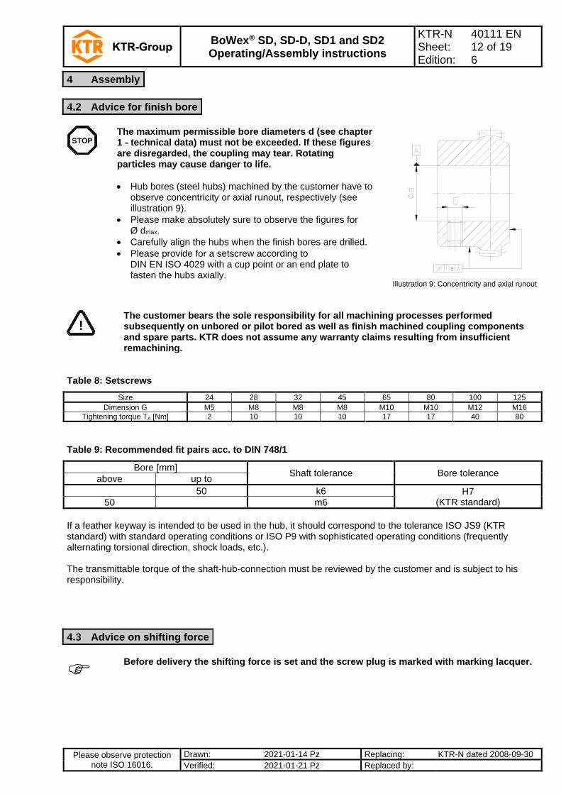
Components of the BoWex® SD1 with shiftable linkage
Component Quantity Description
Illustration 8: BoWex® SD1 with shiftable linkage
1 1 Hub
2 1 Shifting part
3 1 Shiftable linkage
4 1 Slip ring
5 2 Setscrews DIN EN ISO 4029
3 Storage, transport and packaging
3.2 Transport and packaging
4 Assembly
4.1 Components of the couplings
BoWex® SD, SD-D, SD1 and SD2 Operating/Assembly instructions
KTR-N Sheet: Edition:
40111 EN 12 of 19 6
Please observe protection note ISO 16016.
Drawn: 2021-01-14 Pz Replacing: KTR-N dated 2008-09-30
Verified: 2021-01-21 Pz Replaced by:
STOP
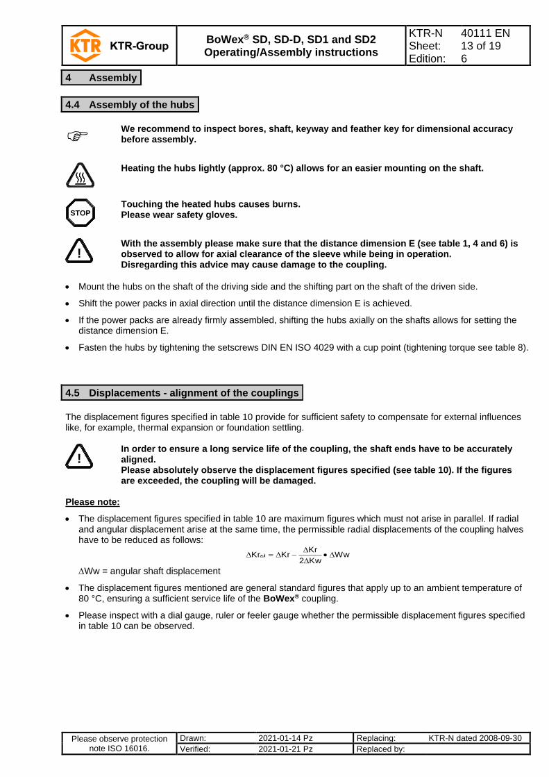
The maximum permissible bore diameters d (see chapter 1 - technical data) must not be exceeded. If these figures are disregarded, the coupling may tear. Rotating particles may cause danger to life.
• Hub bores (steel hubs) machined by the customer have to observe concentricity or axial runout, respectively (see illustration 9).
• Please make absolutely sure to observe the figures for Ø dmax.
• Carefully align the hubs when the finish bores are drilled.
• Please provide for a setscrew according to DIN EN ISO 4029 with a cup point or an end plate to fasten the hubs axially.
Illustration 9: Concentricity and axial runout
!
The customer bears the sole responsibility for all machining processes performed subsequently on unbored or pilot bored as well as finish machined coupling components and spare parts. KTR does not assume any warranty claims resulting from insufficient remachining.
Table 8: Setscrews
Size 24 28 32 45 65 80 100 125
Dimension G M5 M8 M8 M8 M10 M10 M12 M16
Tightening torque TA [Nm] 2 10 10 10 17 17 40 80
Table 9: Recommended fit pairs acc. to DIN 748/1
Bore [mm] Shaft tolerance Bore tolerance
above up to
50 k6 H7 (KTR standard) 50 m6
If a feather keyway is intended to be used in the hub, it should correspond to the tolerance ISO JS9 (KTR standard) with standard operating conditions or ISO P9 with sophisticated operating conditions (frequently alternating torsional direction, shock loads, etc.). The transmittable torque of the shaft-hub-connection must be reviewed by the customer and is subject to his responsibility.
Before delivery the shifting force is set and the screw plug is marked with marking lacquer.
4 Assembly
4.2 Advice for finish bore
4.3 Advice on shifting force
BoWex® SD, SD-D, SD1 and SD2 Operating/Assembly instructions
KTR-N Sheet: Edition:
40111 EN 13 of 19 6
Please observe protection note ISO 16016.
Drawn: 2021-01-14 Pz Replacing: KTR-N dated 2008-09-30
Verified: 2021-01-21 Pz Replaced by:
We recommend to inspect bores, shaft, keyway and feather key for dimensional accuracy before assembly.
Heating the hubs lightly (approx. 80 °C) allows for an easier mounting on the shaft.
STOP
Touching the heated hubs causes burns. Please wear safety gloves.
!
With the assembly please make sure that the distance dimension E (see table 1, 4 and 6) is observed to allow for axial clearance of the sleeve while being in operation. Disregarding this advice may cause damage to the coupling.
• Mount the hubs on the shaft of the driving side and the shifting part on the shaft of the driven side.
• Shift the power packs in axial direction until the distance dimension E is achieved.
• If the power packs are already firmly assembled, shifting the hubs axially on the shafts allows for setting the distance dimension E.
• Fasten the hubs by tightening the setscrews DIN EN ISO 4029 with a cup point (tightening torque see table 8).
The displacement figures specified in table 10 provide for sufficient safety to compensate for external influences like, for example, thermal expansion or foundation settling.
!
In order to ensure a long service life of the coupling, the shaft ends have to be accurately aligned. Please absolutely observe the displacement figures specified (see table 10). If the figures are exceeded, the coupling will be damaged.
Please note:
• The displacement figures specified in table 10 are maximum figures which must not arise in parallel. If radial and angular displacement arise at the same time, the permissible radial displacements of the coupling halves have to be reduced as follows:
WwKw2
KrKrKrzul •
−=
Ww = angular shaft displacement
• The displacement figures mentioned are general standard figures that apply up to an ambient temperature of 80 °C, ensuring a sufficient service life of the BoWex® coupling.
• Please inspect with a dial gauge, ruler or feeler gauge whether the permissible displacement figures specified in table 10 can be observed.
4 Assembly
4.4 Assembly of the hubs
4.5 Displacements - alignment of the couplings

BoWex® SD, SD-D, SD1 and SD2 Operating/Assembly instructions
KTR-N Sheet: Edition:
40111 EN 14 of 19 6
Please observe protection note ISO 16016.
Drawn: 2021-01-14 Pz Replacing: KTR-N dated 2008-09-30
Verified: 2021-01-21 Pz Replaced by:
Angular displacements Radial displacements Axial displacements Radial and angular displacements
Illustration 10: Displacements
Examples of the displacement combinations specified in illustration 11: Example 1:
Kr = 30 %
Kw = 70 % Example 2:
Kr = 60 %
Kw = 40 %
Illustration 11: Combinations of
displacement
Ktotal = Kr + Kw 100 %
Table 10: Displacement figures
Size 24 28 32 45 65 80 100 125
Max. axial displacement Ka [mm] ±1 ±1 ±1 ±1 ±1 ±1 ±1 ±1
Max. radial displacement with n=1500 rpm
Kr [mm] 0.2 0.2 0.25 0.25 0.3 0.3 0.3 0.3
Kw [degree] max. angular displacement with n=1500 rpm
1 1 1 1 1 1 1 1
• Before assembly please inspect the slip ring (component 1, picture 12) to see whether a lubricating nipple/Stauffer lubricator or any damages exist.
• Before separating the slip ring halves mark the position of the slip ring halves screwed by the manufacturer.
• Insert the untightened slip ring halves into the shifting keyway of the coupling.
!
With the assembly pay attention to the position of the slip ring halves marked.
4 Assembly
4.5 Displacements - alignment of the couplings
4.6 Assembly of the slip ring for BoWex® SD1 and SD2

BoWex® SD, SD-D, SD1 and SD2 Operating/Assembly instructions
KTR-N Sheet: Edition:
40111 EN 15 of 19 6
Please observe protection note ISO 16016.
Drawn: 2021-01-14 Pz Replacing: KTR-N dated 2008-09-30
Verified: 2021-01-21 Pz Replaced by:
• Tighten the connection screws with a dynamometric screwdriver. For tightening torques see table 11.
!
After assembly the slip ring must rotate manually.
Table 11:
Slip ring size 1.1 2.2 3.3 4.4 5.5 6.6 7.7 8.8
Screw DIN EN ISO 4017 - 8.8 M6 M8 M8 M10 M12 M16 M16 M16
Tightening torque TA [Nm] 10 25 25 49 86 210 210 210
Max. perm. speed rpm 3200 2500 2100 1700 1300 1200 1000 850
• Grease the slip ring through the lubricating nipple/Stauffer lubricator with a heat resistant bearing grease while rotating the slip ring manually several times. Slip ring - max. permissible speeds see table 11.
Shifting hub:
• Within the framework of the machine inspection periods the fit of the shifting hub has to be cleaned and lubricated (e. g. with Molykote MoS2, copper paste).
• With a high shifting frequency of the coupling we recommend one visual inspection and lubrication of the shifting hub monthly.
• In case of operation with dust and granular material as well as high air humidity one visual inspection and lubrication per month and an operational inspection every three months has to be performed (engagement/disengagement of the coupling at standstill).
Slip ring:
• Before every lubrication the slip ring has to be inspected for damages (visual inspection).
• The shifting hub part must be able to be manually rotated freely in the slip ring.
• The lubrication of the slip ring depends on the speed and the operating periods of the machine (see table 12).
• The intervals for inspection and lubrication specified apply for drives with standard load.
For drives with high load, e. g. permanent operation during 3 shifts, hot operation, etc., please consult with us.
Table 12:
Max. perm. speed [rpm] of the slip rings 3200 to 2100 1700 to 1000 850 to 700
Daily operating period of machines (h) 8 16 8 16 8 16
Visual inspection and lubrication intervals 1/2 month 1 month 1/2 month 1 1/2 months 1 month
!
For certain applications, e. g. operation with dust and granulated materials, high air humidity, high ambient temperatures, outdoor operations, etc., the intervals of visual inspections and lubrication have to be reduced.
4 Assembly
4.6 Assembly of the slip ring for BoWex® SD1 and SD2
4.7 Maintenance intervals for BoWex® SD1 and SD2
BoWex® SD, SD-D, SD1 and SD2 Operating/Assembly instructions
KTR-N Sheet: Edition:
40111 EN 16 of 19 6
Please observe protection note ISO 16016.
Drawn: 2021-01-14 Pz Replacing: KTR-N dated 2008-09-30
Verified: 2021-01-21 Pz Replaced by:
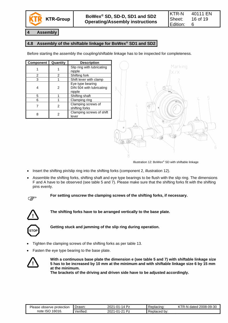
Before starting the assembly the coupling/shiftable linkage has to be inspected for completeness.
Component Quantity Description
Illustration 12: BoWex® SD with shiftable linkage
1 1 Slip ring with lubricating nipple
2 2 Shifting fork
3 1 Shift lever with clamp
4 2 Eye type bearing DIN 504 with lubricating nipple
5 1 Shifting shaft
6 1 Clamping ring
7 2 Clamping screws of shifting forks
8 2 Clamping screws of shift lever
• Insert the shifting pin/slip ring into the shifting forks (component 2, illustration 12).
• Assemble the shifting forks, shifting shaft and eye type bearings to be flush with the slip ring. The dimensions F and A have to be observed (see table 5 and 7). Please make sure that the shifting forks fit with the shifting pins evenly.
For setting unscrew the clamping screws of the shifting forks, if necessary.
!
The shifting forks have to be arranged vertically to the base plate.
STOP
Getting stuck and jamming of the slip ring during operation.
• Tighten the clamping screws of the shifting forks as per table 13.
• Fasten the eye type bearing to the base plate.
!
With a continuous base plate the dimension e (see table 5 and 7) with shiftable linkage size 5 has to be increased by 10 mm at the minimum and with shiftable linkage size 6 by 15 mm at the minimum. The brackets of the driving and driven side have to be adjusted accordingly.
4 Assembly
4.8 Assembly of the shiftable linkage for BoWex® SD1 and SD2
BoWex® SD, SD-D, SD1 and SD2 Operating/Assembly instructions
KTR-N Sheet: Edition:
40111 EN 17 of 19 6
Please observe protection note ISO 16016.
Drawn: 2021-01-14 Pz Replacing: KTR-N dated 2008-09-30
Verified: 2021-01-21 Pz Replaced by:
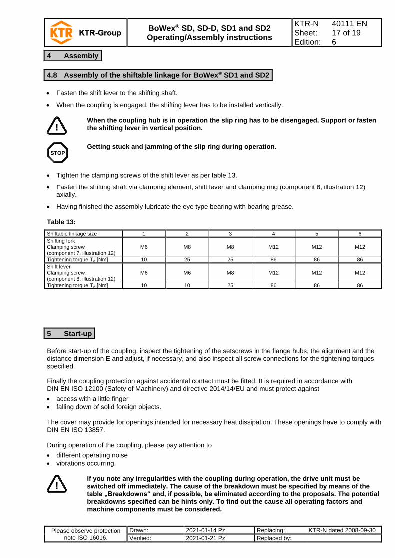
• Fasten the shift lever to the shifting shaft.
• When the coupling is engaged, the shifting lever has to be installed vertically.
!
When the coupling hub is in operation the slip ring has to be disengaged. Support or fasten the shifting lever in vertical position.
STOP
Getting stuck and jamming of the slip ring during operation.
• Tighten the clamping screws of the shift lever as per table 13.
• Fasten the shifting shaft via clamping element, shift lever and clamping ring (component 6, illustration 12) axially.
• Having finished the assembly lubricate the eye type bearing with bearing grease. Table 13:
Shiftable linkage size 1 2 3 4 5 6
Shifting fork Clamping screw (component 7, illustration 12)
M6 M8 M8 M12 M12 M12
Tightening torque TA [Nm] 10 25 25 86 86 86
Shift lever Clamping screw (component 8, illustration 12)
M6 M6 M8 M12 M12 M12
Tightening torque TA [Nm] 10 10 25 86 86 86
Before start-up of the coupling, inspect the tightening of the setscrews in the flange hubs, the alignment and the distance dimension E and adjust, if necessary, and also inspect all screw connections for the tightening torques specified. Finally the coupling protection against accidental contact must be fitted. It is required in accordance with DIN EN ISO 12100 (Safety of Machinery) and directive 2014/14/EU and must protect against
• access with a little finger
• falling down of solid foreign objects. The cover may provide for openings intended for necessary heat dissipation. These openings have to comply with DIN EN ISO 13857. During operation of the coupling, please pay attention to
• different operating noise
• vibrations occurring.
!
If you note any irregularities with the coupling during operation, the drive unit must be switched off immediately. The cause of the breakdown must be specified by means of the table „Breakdowns“ and, if possible, be eliminated according to the proposals. The potential breakdowns specified can be hints only. To find out the cause all operating factors and machine components must be considered.
4 Assembly
4.8 Assembly of the shiftable linkage for BoWex® SD1 and SD2
5 Start-up
BoWex® SD, SD-D, SD1 and SD2 Operating/Assembly instructions
KTR-N Sheet: Edition:
40111 EN 18 of 19 6
Please observe protection note ISO 16016.
Drawn: 2021-01-14 Pz Replacing: KTR-N dated 2008-09-30
Verified: 2021-01-21 Pz Replaced by:
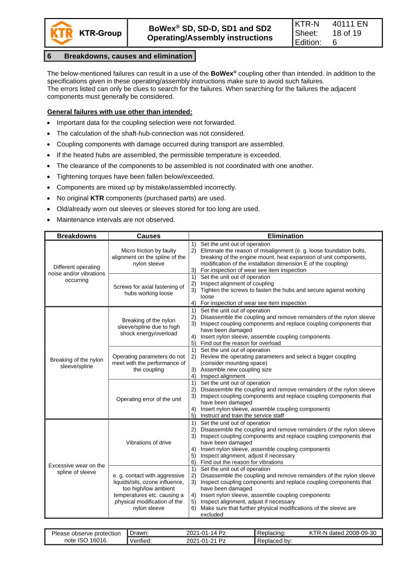
The below-mentioned failures can result in a use of the BoWex® coupling other than intended. In addition to the specifications given in these operating/assembly instructions make sure to avoid such failures. The errors listed can only be clues to search for the failures. When searching for the failures the adjacent components must generally be considered. General failures with use other than intended:
• Important data for the coupling selection were not forwarded.
• The calculation of the shaft-hub-connection was not considered.
• Coupling components with damage occurred during transport are assembled.
• If the heated hubs are assembled, the permissible temperature is exceeded.
• The clearance of the components to be assembled is not coordinated with one another.
• Tightening torques have been fallen below/exceeded.
• Components are mixed up by mistake/assembled incorrectly.
• No original KTR components (purchased parts) are used.
• Old/already worn out sleeves or sleeves stored for too long are used.
• Maintenance intervals are not observed.
Breakdowns Causes Elimination
Different operating noise and/or vibrations
occurring
Micro friction by faulty alignment on the spline of the
nylon sleeve
1) Set the unit out of operation 2) Eliminate the reason of misalignment (e. g. loose foundation bolts,
breaking of the engine mount, heat expansion of unit components, modification of the installation dimension E of the coupling)
3) For inspection of wear see item inspection
Screws for axial fastening of hubs working loose
1) Set the unit out of operation 2) Inspect alignment of coupling 3) Tighten the screws to fasten the hubs and secure against working
loose 4) For inspection of wear see item inspection
Breaking of the nylon sleeve/spline
Breaking of the nylon sleeve/spline due to high shock energy/overload
1) Set the unit out of operation 2) Disassemble the coupling and remove remainders of the nylon sleeve 3) Inspect coupling components and replace coupling components that
have been damaged 4) Insert nylon sleeve, assemble coupling components 5) Find out the reason for overload
Operating parameters do not meet with the performance of
the coupling
1) Set the unit out of operation 2) Review the operating parameters and select a bigger coupling
(consider mounting space) 3) Assemble new coupling size 4) Inspect alignment
Operating error of the unit
1) Set the unit out of operation 2) Disassemble the coupling and remove remainders of the nylon sleeve 3) Inspect coupling components and replace coupling components that
have been damaged 4) Insert nylon sleeve, assemble coupling components 5) Instruct and train the service staff
Excessive wear on the spline of sleeve
Vibrations of drive
1) Set the unit out of operation 2) Disassemble the coupling and remove remainders of the nylon sleeve 3) Inspect coupling components and replace coupling components that
have been damaged 4) Insert nylon sleeve, assemble coupling components 5) Inspect alignment, adjust if necessary 6) Find out the reason for vibrations
e. g. contact with aggressive liquids/oils, ozone influence,
too high/low ambient temperatures etc. causing a physical modification of the
nylon sleeve
1) Set the unit out of operation 2) Disassemble the coupling and remove remainders of the nylon sleeve 3) Inspect coupling components and replace coupling components that
have been damaged 4) Insert nylon sleeve, assemble coupling components 5) Inspect alignment, adjust if necessary 6) Make sure that further physical modifications of the sleeve are
excluded
6 Breakdowns, causes and elimination
BoWex® SD, SD-D, SD1 and SD2 Operating/Assembly instructions
KTR-N Sheet: Edition:
40111 EN 19 of 19 6
Please observe protection note ISO 16016.
Drawn: 2021-01-14 Pz Replacing: KTR-N dated 2008-09-30
Verified: 2021-01-21 Pz Replaced by:
In respect of environmental protection we would ask you to dispose of the packaging or products on termination of their service life in accordance with the legal regulations and standards that apply, respectively.
• Metal Any metal components have to be cleaned and disposed of by scrap metal.
• Nylon materials Nylon materials have to be collected and disposed of by a waste disposal company.
A basic requirement to ensure the readiness for use of the coupling is a stock of the most important spare parts on site. Contact addresses of the KTR partners for spare parts and orders can be obtained from the KTR homepage at www.ktr.com.
KTR does not assume any liability or warranty for the use of spare parts and accessories which are not provided by KTR and for the damages which may incur as a result.
7 Disposal
8 Spares inventory, customer service addresses