table of contents section 4 -...
TRANSCRIPT
4-1© 2012 Schneider ElectricAll Rights Reserved
4P
OW
ER
MO
NIT
OR
ING
AN
D
CO
NT
RO
L
Table of Contents
Section 4Power Monitoring and Control
Power Monitoring software
CM4000 ION7650
HDM4 Panel
StrucureWare Energy Operation
Sepam series 80
Low VoltageAutomatic Capacitor
Bank
Active Harmonic Filter
PowerLogic™ Energy and Power Management Systems
Introduction 4-2, 4-3Power Monitoring Software
StruxureWare Power Monitoring Expert 4-4StruxureWare PowerMonitoring Expert for Data Centers
4-4
StruxureWare PowerMonitoring Expert for Healthcare
4-4
StruxureWare Power SCADA Expert 4-5PowerLogic ION EEM Enterprise EnergyManagement Software
4-6
PowerLogic MeteringION8650 4-7ION7550/7650 4-7ION7350/7330/7300 4-8ION6200 4-8PowerLogic ION Meter Selection 4-9DM6200 Panel Meter 4-10PM1200 Multifunctional Power Meter 4-10Series 800 Power Meter 4-10Series 3500 Power Meter 4-11Series 4000 Circuit Monitor 4-11Series 5000 Power Meter 4-12
SubmeteringTenant Metering Software 4-13PowerLogic E5600 Socket Meter 4-13High Density Meter Enclosures (HDM) 4-14Multi Circuit Energy Meters 4-14Energy Meter 4-15Enercept™ Meter 4-15Split Core Current Transformers 4-15Branch Circuit Power Meter 4-16Branch Current Monitor 4-16Multi-Circuit Meter 4-16Submeter Display 4-16
CommunicationsCommX 200 Data Logger 4-17Ethernet Gateways 4-18Web Page Generator 4-18
Engineering ServicesConsulting & Analysis 4-19Industrial Energy Efficiency 4-19Power Monitoring Applications 4-20Power System Control Applications 4-20System Integration 4-20Factory Assembled Enclosures 4-21Technical Support 4-22Power Management University 4-22
Sepam Digital Protective Relays
Series 80, 60, 40 & 20 Features 4-23Series 80, 60, 40, 20 & 10 Applications 4-24
Arc Flash Protection and Mitigation Systems
VAMP 221 4-25
ReactiVar™ Reactive Power Compensation and Harmonic Mitigation Solutions
Reactive Power Compensation and Harmonic Mitigation Solutions 4-27Low Voltage Fixed Capacitor 4-28Low Voltage Automatic Capacitor Banks 4-30LV Transient Free Reactive Compensation Banks 4-31Medium Voltage Capacitors 4-32Accusine™ PCS Active Harmonic Filter 4-33Hybrid VAR Compensator (HVC) 4-35
Courtesy of Steven Engineering, Inc. - (800) 258-9200 - [email protected] - www.stevenengineering.com
www.powerlogic.com
4P
OW
ER
MO
NIT
OR
ING
AN
D
CO
NT
RO
L
4-2 © 2012 Schneider ElectricAll Rights Reserved
PowerLogic™
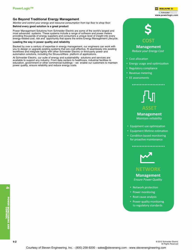
Go Beyond Traditional Energy ManagementMonitor and control your energy and resource consumption from top floor to shop floor.Behind every good solution is a great product
Power Management Solutions from Schneider Electric are some of the world's largest and most advanced systems. These systems include a range of software and power meters providing thousands of energy suppliers and consumers a unique level of insight into every energy-related cost, risk and opportunity that spans the entire Energy Management Lifecycle.Leading the way in power quality and reliability
Backed by over a century of expertise in energy management, our engineers can work with you to design or upgrade existing systems that are cost-effective, fit seamlessly into existing workflows and integrate tightly with other Schneider Electric or third-party power and automation solutions, including the StruxureWare platform of applications.At Schneider Electric, our suite of energy and sustainability solutions and services are available to support any industry. From data centers to healthcare, industrial facilities to education, government or other commercial buildings – we enable our customers to maintain power quality, ensure reliability and reduce energy costs.
NETWORKManagement
Ensure Power Quality
• Network protec�on
• Power monitoring
• Root cause analysis
• Power quality monitoringto regulatory standards
ASSETManagement
Maintain reliability
• Equipment use op�miza�on
• Equipment life�me es�ma�on
• Condi�on based monitoringfor proac�ve maintenance
COSTManagement
Reduce your Energy Cost
• Cost alloca�on
• Energy usage and op�miza�on
• Regulatory compliance
• Revenue metering
• EE assessments
Courtesy of Steven Engineering, Inc. - (800) 258-9200 - [email protected] - www.stevenengineering.com
www.powerlogic.com
4P
OW
ER
MO
NIT
OR
ING
AN
D
CO
NT
RO
L
© 2012 Schneider ElectricAll Rights Reserved
4-3
PowerLogic™
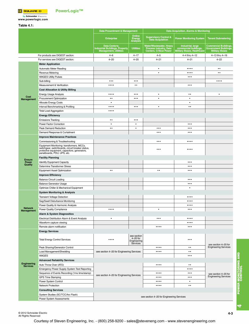
Table 4.1:
Data Presentment & Management Data Acquisition, Alarms & Monitoring
EnterpriseOnline Energy
Analysis
Supervisory Control &Data Acquisition Power Monitoring System Tenant Submetering
Data Centers;Industrial Buildings, Property
Management, UtilitiesUtilities
Water/Wastewater, Heavy Process Industry, Data Centers, Critical Power
Industrial, large commercial buildings,
Military Bases, Healthcare
Commercial Buildings, Government Buildings,
Military Bases
For products see DIGEST section: 4–6 4–17 4–5 4–4 thru 4–12 4–13 thru 4–16
For services see DIGEST section: 4–20 4–20 4–21 4–21 4–22
CostManagement
Meter Application
Automatic Meter Reading • • • • • • •
Revenue Metering • • • • • • •
WAGES Utility Pulses • • •
Sub-billing • • • • • • • • • •
Measurement & Verification • • • • • • • • •
Cost Allocation & Utility Billing
Energy Usage Analysis • • • • • • • • • • •
Procurement Optimization • • • • • • •
Allocate Energy Costs • •
Interval Benchmarking & Profiling • • • • • • • • • •
Total Load Aggregation • • • •
Energy Efficiency
Emissions Tracking • • • • •
Power Factor Correction • • • • •
Peak Demand Reduction • • • • • • • • •
Demand Response & Curtailment • • • • • •
EnsurePowerQuality
Improve Maintenance Practices
Commissioning & Troubleshooting • • • • • • •
Equipment Monitoring: transformers, MCCs, switchgear, switchboards, circuit breaker status, protective equipment, capacitors, generators, panelboards, PDU, UPS, etc.
• • • • • • •
Facility Planning
Identify Equipment Capacity • • •
Determine Transformer Stress • • •
Equipment Asset Optimization • • • • • • •
Improve Efficiency
Balance Circuit Loading • • •
Balance Generator Usage • • •
Optimize Chiller & Mechanical Equipment •
NetworkManagement
System Monitoring & Analysis
Transient Voltage Detection • • • •
Sag/Swell Disturbance Monitoring • • • •
Power Quality & Harmonic Analysis • • • •
Power Quality Compliance • • • • • • • •
Alarm & System Diagnositics
Electrical Distribution Alarm & Event Analysis • • • • • • • •
Waveform capture viewing • • • •
Remote alarm notification • • • • • • •
Engineering Services
Energy Services
Total Energy Control Services • • • •
see section 4–20 for
Engineering Services
• • •
see section 4–20 for Engineering ServicesPeak Shaving/Generator Control
see section 4–20 for Engineering Services
• • • • • •
Load Management/Shedding • • • • • •
WAGES • • •
Advanced Reliability Services
Auto Throw Over (ATO)
see section 4–20 for Engineering Services
• • • • • •
see section 4–20 for Engineering Services
Emergency Power Supply System Test Reporting • • • •
Sequence of Events Recording (1ms time/stamp) • • • • • • •
GPS Time Stamping • • • • • • •
Power System Control • • • • •
Network Protection • • • • • •
Consulting Services
System Studies (SC/TCC/Arc Flash)see section 4–20 for Engineering Services
Power System Assessments
Courtesy of Steven Engineering, Inc. - (800) 258-9200 - [email protected] - www.stevenengineering.com
4-4 © 2012 Schneider ElectricAll Rights Reserved
www.powerlogic.com
4P
OW
ER
MO
NIT
OR
ING
AN
D
CO
NT
RO
L
PowerLogic™ StruxureWare Power Monitoring Software
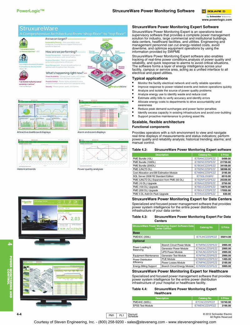
StruxureWare Power Monitoring Expert SoftwareStruxureWare Power Monitoring Expert is an operations-level supervisory software that provides a complete power management solution for industry, large commercial and institutional buildings, data centers, healthcare facilities, and utilities. Engineering and management personnel can cut energy-related costs, avoid downtime, and optimize equipment operations by using the information provided by SWPMEStruxureWare Power Monitoring Expert software also enables tracking of real-time power conditions,analysis of power quality and reliability, and quick response to alarms to avoid critical situations. The software forms a layer of energy intelligence across your facility, campus or service area, acting as a unified interface to all electrical and piped utilities.
Typical applications• Monitor the facility electrical network and verify reliable operation• Improve response to power-related events and restore operations quickly• Analyze and isolate the source of power quality problems• Analyze energy use to identify waste and reduce cost• Estimate utility bills to verify accuracy and identify errors• Allocate energy costs to departments to drive accountability and
awareness• Reduce peak demand surcharges and power factor penalties• Identify excess capacity in existing infrastructure and avoid over-building• Support proactive maintenance to prolong asset life.
Scalable, flexible architectureFunctional components
Provides operators with a rich environment to view and navigate real-time displays of measurements and status indicators; perform power quality and reliability analysis; historical trending; alarms; and manual control.
StruxureWare Power Monitoring Expert for Data CentersSpecialized and focused power management software that provides power system intelligence for the entire power distribution infrastructure of your data center.
StruxureWare Power Monitoring Expert for HealthcareSpecialized and focused power management software that provides power system intelligence for the entire power distribution infrastructure of your hospital or healthcare facility.
Table 4.2: StruxureWare Power Monitoring Expert softwareDescription Catalog No. $ Price
PME Bundle (10L) IE7BANCZZSPEZZ 5499.00PME Bundle (100DL) IE7BENCZZSPEZZ 21739.00PME Bundle (200DL) IE7BGNCZZSPEZZ 34109.00PME (UNLTD DL) IE7BZNCZZSPEZZ 38398.00Cost Allocation and Bill Estimation Module IE7MBNCZZSPEZZ 2195.00SQL Server 2008 R2 Standard Edition IE7SQL2008R2 6510.00PME (UNLTD DL) Expansion from PME (50 DL) IE7BZNPDZSPEZZ 25339.00PME (10 DL) Upgrade IE7BAUCZZSPEZZ 2750.00PME (100 DL) Upgrade IE7BEUCZZSPEZZ 10870.00PME (200 DL) Upgrade IE7BGUCZZSPEZZ 17055.00PME 5 DL Add-On Pack Upgrade IE7D5UCZZSPEZZ 630.00
Table 4.3: StruxureWare Power Monitoring Expert For Data Centers
StruxureWare Power Monitoring Expert Software Data Center Edition Catalog No. $ Price
BasePME4DC (200L) IE7XJNCZZSPEZZ 35814.00
Optional
Power Loading & Balancing
Branch Circuit Power Mode IE7MRNCZZSPEZZ 2995.00Generator Power Module IE7MGNCZZSPEZZ 2995.00UPS Power Module IE7MUNCZZSPEZZ 2995.00
Equipment Maintenance Generator Test Module IE7MTNCZZSPEZZ 2995.00
Power Distribution Efficiency
PUE Module IE7MWNCZZSPEZZ 1495.00Power Losses Module IE7MPNCZZSPEZZ 2195.00
Energy Billing Support Branch Circuit Energy Module IE7MSNCZZSPEZZ 5995.00
Table 4.4: StruxureWare Power Monitoring Expert HealthcareDescription Catalog No. $ Price
PME4HC (50DL) IE7CNCZZSPEZZ 15740.00EPSS Test Module IE7MENCZZSPEZZ 2195.00
PM1 PL1 Discount Schedule
Courtesy of Steven Engineering, Inc. - (800) 258-9200 - [email protected] - www.stevenengineering.com
www.powerlogic.com
4P
OW
ER
MO
NIT
OR
ING
AN
D
CO
NT
RO
L
© 2012 Schneider ElectricAll Rights Reserved
4-5
PowerLogic™ StruxureWare Power Monitoring Software
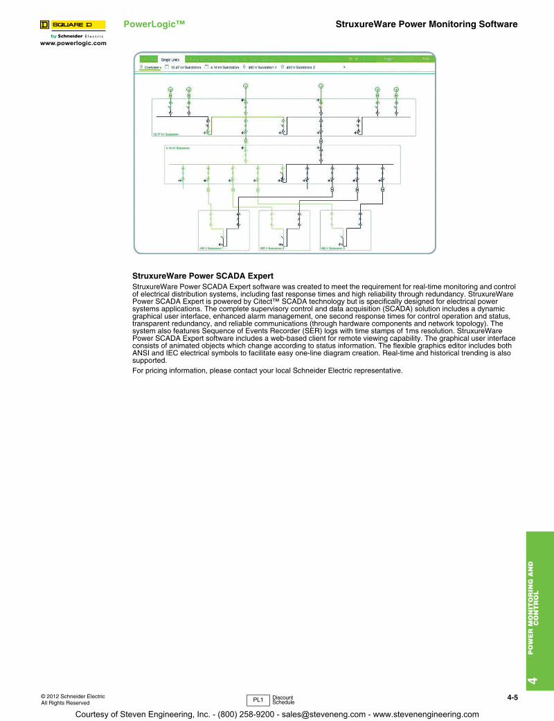
StruxureWare Power SCADA ExpertStruxureWare Power SCADA Expert software was created to meet the requirement for real-time monitoring and control of electrical distribution systems, including fast response times and high reliability through redundancy. StruxureWare Power SCADA Expert is powered by Citect™ SCADA technology but is specifically designed for electrical power systems applications. The complete supervisory control and data acquisition (SCADA) solution includes a dynamic graphical user interface, enhanced alarm management, one second response times for control operation and status, transparent redundancy, and reliable communications (through hardware components and network topology). The system also features Sequence of Events Recorder (SER) logs with time stamps of 1ms resolution. StruxureWare Power SCADA Expert software includes a web-based client for remote viewing capability. The graphical user interface consists of animated objects which change according to status information. The flexible graphics editor includes both ANSI and IEC electrical symbols to facilitate easy one-line diagram creation. Real-time and historical trending is also supported.For pricing information, please contact your local Schneider Electric representative.
PL1 Discount Schedule
Courtesy of Steven Engineering, Inc. - (800) 258-9200 - [email protected] - www.stevenengineering.com
www.powerlogic.com
4P
OW
ER
MO
NIT
OR
ING
AN
D
CO
NT
RO
L
4-6 © 2012 Schneider ElectricAll Rights Reserved
PowerLogic™ ION EEM Enterprise Energy Management Software
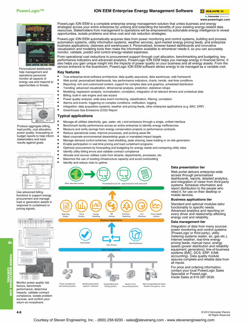
PowerLogic ION EEM is a complete enterprise energy management solution that unites business and energy strategies across your entire enterprise by unifying and extending the benefits of your existing energy-related data resources. Stakeholders from management to operations will be empowered by actionable energy intelligence to reveal opportunities, isolate problems and drive cost and risk reduction strategies.
PowerLogic ION EEM automatically acquires data from power monitoring and control systems, building and process automation systems, utility information systems, weather services, spot-market energy pricing feeds, and enterprise business applications, cleanses and warehouses it. Personalized, browser-based dashboards and innovative visualization and modeling tools then make the information available to whomever needs it, so you can accurately monitor, validate, predict and control energy-related expenses.From operational cost reductions to procurement support through cost allocation, benchmarking and budgeting, key performance indicators and advanced analytics, PowerLogic ION EEM helps you manage energy in financial terms. It also helps you gain unique insight into the impacts of power quality on your business and all energy assets. From the service entrance to the boardroom, PowerLogic ION EEM software allows energy to be managed as a variable cost.
Key features• True enterprise-level software architecture: data quality assurance, data warehouse, web framework• Web portal: personalized dashboards, key performance indicators, charts, trends, real-time conditions• Reporting: rich and customized content, support for complex data and graphics, scheduled distribution• Trending: advanced visualization, dimensional analysis, prediction, statistical rollups• Modeling: regression analysis, normalization, correlation, integration of all relevant drivers and contextual data• Billing: built-in rate engine and rate wizard• Power quality analysis: wide-area event monitoring, classification, filtering, correlation• Alarms and events: triggering on complex conditions, notification, logging• Integration: data acquisition systems, weather and pricing feeds, other enterprise applications (e.g. BAC, ERP)• Greenhouse Gas Emissions (CO2) Report
Typical applications
• Manage all utilities (electricity, gas, water, etc.) and emissions through a single, unified interface• Benchmark facility performance across an entire enterprise to identify energy inefficiencies• Measure and verify savings from energy conservation projects or performance contracts• Reduce operational costs, improve processes, and prolong asset life• Meet corporate environmental stewardship goals or mandated impact targets• Manage demand control schemes, load shedding, peak shaving, base loading or on-site generation• Enable participation in real-time pricing and load curtailment programs• Optimize procurement by forecasting and budgeting for energy needs and comparing utility rates• Identify utility billing errors and validate contract compliance• Allocate and recover utilities costs from tenants, departments, processes, etc.• Maximize the use of existing infrastructure capacity and avoid overbuilding• Identify and reduce risks to uptime
Data presentation tierWeb portal delivers enterprise-wide access through personalized dashboards, reports, detailed analytics, and integration of views from third-party systems. Schedule information and report distribution to the people who need it, for use on their desktop or mobile devices.Business applications tierStandard and optional modules tailor functionality to specific needs. Advanced analytics and reporting on every driver and relationship affecting energy cost and reliability.Data management tierIntegration of data from many sources: power monitoring and control systems (PowerLogic or third party), utility metering systems (water, air, gas etc.), Internet weather, real-time energy pricing feeds, manual input, energy assets (power distribution and reliability equipment, generators), line-of-business systems (BAC, DCS, ERP, EAM, accounting). Data quality module assures complete and reliable data from all inputs.For price and ordering information, contact your local PowerLogic Sales Specialist or PowerLogicInside Sales at 615-287-3535.
Personalized dashboards help management and operations personnel monitor all aspects of energy use and respond to opportunities or threats.
Produce aggregate billing, load profile, cost allocation, power quality, forecasting or budget reports to help inform stakeholders and track results against goals.
Use advanced billing functions to support energy procurement and manage load or generation assets in response to curtailment or pricing signals.
Monitor power quality risk factors, benchmark performance, determine impacts, validate contract compliance, isolate problem sources, and confirm your return-on-investment.
Power management
and metering systems
Building Automation
Sytems P roductionEnergy Billing And
Pricing Systems
Business And
Accounting Systems
Other Energy-Relevant Inputs
Weather, Occupancy , A rea
Data Quality
Data SharingData W arehouse
Data management
Business Applications
Data Presentations
Reporting
Engine
Trend
Analysis
Energy
Modeling
Bill
Analysis
Emissions
Reporting
Cost
Allocation
Power Quality
Analysis
Other web-base content Personalized access thr ough enterprise-wide web portal
Courtesy of Steven Engineering, Inc. - (800) 258-9200 - [email protected] - www.stevenengineering.com
www.powerlogic.com
4P
OW
ER
MO
NIT
OR
ING
AN
D
CO
NT
RO
L
© 2012 Schneider ElectricAll Rights Reserved
4-7
PowerLogic™ ION8650/7550/7650 Power and Energy Meters
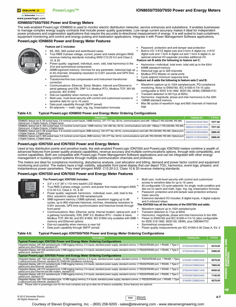
ION8650/7550/7650 Power and Energy MetersThe web-enabled PowerLogic ION8650 is used to monitor electric distribution networks, service entrances and substations. It enables businesses to manage complex energy supply contracts that include power quality guarantees. Low-range current accuracy makes it ideal for independent power producers and cogeneration applications that require the accurate bi-directional measurement of energy. It is well suited to load curtailment, equipment monitoring and control and energy pulsing and totalization applications. Integrate it with Power Management Software applications.
PowerLogic ION8650 Power and Energy Meter Features
PowerLogic ION7550 and ION7650 Power and Energy MetersUsed at key distribution points and sensitive loads, the web-enabled PowerLogic ION7550 and PowerLogic ION7650 meters combine a wealth of advanced features from power quality analysis capabilities, revenue accuracy and multiple communications options, through web compatibility, and control capabilities. Both are compatible with PowerLogic Power Management Software applications and can be integrated with other energy management or building control systems through multiple communication channels and protocols.The meters are ideal for compliance monitoring, disturbance analysis, cost allocation and billing, demand and power factor control and equipment monitoring and control. The meters have a high visibility, adjustable front panel display that can depict TOU, harmonics, event logs, phasers, and instantaneous power parameters. They meet stringent ANSI C12.20 0.2, Class 10 & 20 revenue metering standards.
PowerLogic ION7550 and ION7650 Power and Energy Meter Features
Feature set C includes:
• 9S, 35S, 36S socket and switchboard cases• True RMS 3-phase voltage, current, power and meets stringent ANSI
revenue metering standards including ANSI C12.20 0.2 and Class 2, 10, & 20
• Power quality: sag/swell, individual, even, odd, total harmonics to the 31st and symmetrical components
• 32MB log/event memory, min/max for any parameter, historical logs up to 64 channels, timestamp resolution to 0.001 seconds and GPS time synchronization
• Transformer/line loss compensation and Instrument transformer correction
• Communications: Ethernet, Serial, Modem, Internet and Ethernet to serial gateway and ION, DNP 3.0, Modbus RTU, Modbus TCP, MV-90 protocols, IEC 61850
• Dial-out capability when memory is near full• Multi-user, multi-level security with control and customized access to
sensitive data for up to 16 users • Data push capability through SMTP (email)• 65 setpoints — math, logic, trig, log, linearization formulas
• Password protection and anti-tamper seal protection• Built-in I/O: 4 KYZ digital outs and 3 form A digital ins, 4 KYZ
digital outs and 1 form A digital out and 1 form A digital in, an optional external I/O expander provides additional I/O
Feature set B adds the following to feature set C:
• Harmonics—individual, total even, total odd up to the 63rd• 64MB standard memory• Historical logs up to 320 channels• Modbus RTU Master on serial ports• Cycle setpoint minimum response time Feature set A adds the following to feature sets C and B:
• Waveform capture up to 1024 samples/cycle, PQ compliance monitoring, flicker to EN50160, IEC 61000-4-7/4-15 (also configurable to IEEE 519-1992, IEEE159, SEMI) CBEMA/ITIC
• Transient detection to 6517µs at 60Hz; • Harmonics: magnitude, phase and inter-harmonics to the 50th• 128MB standard memory• Max 96 cycles of waveform logs and 800 channels of historical
logs
Table 4.5: Typical PowerLogic ION8650 Power and Energy Meter Ordering ConfigurationsDescription Catalog No. $ Price
ION8650, feature set A, 9S socket base, 5 A nominal current inputs, 10MB memory, 127–177 Vac, 60 Hz, communications card with: 10BaseT, RS-232/485, RS-485, Optical port, 4 Digital Outputs, 3 Digital Inputs S8650A0C0E6E1B0A 7077.00
ION8650, feature set A, 35S socket base, 5 A nominal current inputs, 10MB memory, 120–480 Vac, 60 Hz, communications card with: 10Base T, RS-232/485, RS-485, Optical port, 4 Digital Outputs, 3 Digital Inputs S8650A1C0E6E1B0A 7077.00
ION8650, feature set C, 9S socket base, 5 A nominal current inputs, 2MB memory, 120–277 Vac, 60 Hz, communications card with: RS-232/485, RS-485, Optical port, 4 Digital Outputs, 3 Digital Inputs S8650C0C0E6A0B0A 2889.00
ION8650, feature set C, 35S socket base, 5 A nominal current inputs, 2MB memory, 120–277 Vac, 60 Hz, communications card with: RS-232/485, RS-485, Optical port, 4 Digital Outputs, 3 Digital Inputs S8650C1C0E6A0B0A 2889.00
The PowerLogic ION7550 includes:
• 3.5” x 4.5” (87 x 112 mm) backlit LCD display• True RMS 3-phase voltage, current, and power that meets stringent ANSI
C12.20 0.2, Class 2, 10, & 20• Power quality: sag/swell, harmonics - individual, even, odd, total to the
63rd, waveform capture at 256 samples/cycle• 5MB log/event memory (10MB optional), waveform logging up to 96
cycles, up to 800 channels historical, min/max, timestamp resolution to 0.001 seconds, GPS time synchronization and historical trends through front panel
• Communications: fiber, Ethernet, serial, internal modem, optical port, and a gateway functionality, ION, DNP 3.0, Modbus RTU - master & slave, Modbus TCP, MV-90, and IEC 61850. IEC 61850 only available with 5MB memory and Ethernet options
• Dial-out capability when memory is near full• Data push capability through SMTP (email)
• Multi-user, multi-level security with control and customized access to sensitive data for up to 16 users
• 65 configurable 1/2 cycle setpoints for single, multi-condition and dial out on alarm and math, logic, trig, log, linearization formulas
• Password protection and anti-tamper seal protection enhance meter security
• Extensive standard I/O includes: 8 digital inputs, 4 digital outputs and 3 onboard relays
The ION7650 has all the features of the ION7550 and adds:
• Waveform capture up to 1024 samples/cycle • Transient detection to 17µs at 60Hz • Harmonics: magnitude, phase and inter-harmonics to the 40th• Flicker to EN50160 and IEC 61000-4-7/4-15 (also configurable
for IEEE 519-1992, IEEE159, SEMI), plus CBEMA/ITIC• Symmetrical components• Power quality measurements per IEC 61000-4-30 Class A, Ed. 2
Table 4.6: Typical PowerLogic ION7550/7650 Power and Energy Meter Ordering ConfigurationsDescription Catalog No. $ Price
Typical PowerLogic ION7550 Power and Energy Meter Ordering ConfigurationsIntegrated display, with 256 samples/cycle, 5 MB logging memory, 5 A inputs, standard power supply, standard comms. (1 RS232/RS485 port, 1 RS485, 1 Type 2 optical port) plus Ethernet, standard I/O S7550A0C0B6E0A0A 6318.00
Integrated display, with 256 samples/cycle, 5 MB logging memory, 5 A inputs, standard power supply, standard comms. (1 RS232/RS485 port, 1 RS485, 1 Type 2 optical port), standard I/O S7550A0C0B6A0A0A 5589.00
Typical PowerLogic ION7650 Power and Energy Meter Ordering ConfigurationsIntegrated display, with 1024 samples/cycle, 10 MB logging memory, 5 A inputs, standard power supply, standard comms. (1 RS232/RS485 port, 1 RS485, 1 Type 2 optical port) plus Ethernet, standard I/O, EN50160 compliance monitoring S7650B1C0B6E0A0E 9279.00
Integrated display, with 512 samples/cycle, 5 MB logging memory, 5 A inputs, standard power supply, standard comms. (1 RS232/RS485 port, 1 RS485, 1 Type 2 optical port) plus Ethernet, standard I/O S7650A0C0B6E0A0A 7869.00
Integrated display, with 512 samples/cycle, 5 MB logging memory, 5 A inputs, standard power supply, standard comms. (1 RS232/RS485 port, 1 RS485, 1 Type 2 optical port) plus Ethernet and 56k modem, standard I/O S7650A0C0B6C1A0A 8409.00
Integrated display, with 512 samples/cycle, 5 MB logging memory, 5 A inputs, standard power supply, standard comms. (1 RS232/RS485 port, 1 RS485, 1 Type 2 optical port), standard I/O S7650A0C0B6A0A0A 7140.00
Integrated display, with 1024 samples/cycle, 10 MB logging memory, 5 A inputs, standard power supply, standard comms. (1 RS232/RS485 port, 1 RS485, 1 Type 2 optical port) plus Ethernet, standard I/O S7650B1C0B6E0A0A 9279.00
Note: Please refer to powerlogic.com for the most complete and up-to-date list of feature availability. Some features are optional.
PM1 DiscountSchedule
Courtesy of Steven Engineering, Inc. - (800) 258-9200 - [email protected] - www.stevenengineering.com

4-8 © 2012 Schneider ElectricAll Rights Reserved
www.powerlogic.com
4P
OW
ER
MO
NIT
OR
ING
AN
D
CO
NT
RO
L
PowerLogic™ ION7350/7330/7300/6200 Power and Energy Meters
Used in diverse applications such as feeder monitoring and sub-metering, the PowerLogic ION7300 series meters are also suitable for high-accuracy power and energy metering, bill verification, cost allocation and billing, demand and power factor control, load studies, circuit optimization, equipment monitoring and control and preventative maintenance. They are ideal replacements for analog meters, with a multitude of power and energy measurements, analog and digital I/O, communication ports and industry-standard protocols. The ION7330 meter adds on-board data storage, emails of logged data and an optional modem. The ION7350 meter is further augmented by more sophisticated power quality analysis, alarms and a call-back-on-alarm feature. They are compatible with Power Management Software applications or can be integrated with other energy management or building control systems through multiple communication channels and protocols.
PowerLogic ION7350, ION7330 and ION7300 Power and Energy Meter Features
The modular PowerLogic ION6200 is a low-cost, ultra-compact meter that offers outstanding versatility and functionality. It is simple to use, and has a big, bright LED display. It offers four-quadrant power, demand, energy, power factor and frequency measurements, and is available in a variety of flexible configurations. It is available as a low-cost base model to which enhanced functionality can be added over the long term. The PowerLogic ION6200 is ideal for customers who need revenue-accurate and/or certified measurements and want easy integration with power distribution assemblies and building automation systems. A Megawatt version is available for applications requiring readings in megawatts and kilovolts. It is well suited for sub-metering, energy cost tracking load profiling, and substation panel metering and is an ideal replacement for analog meters. It can be used for stand-alone metering in custom panels, switchboards, switchgear, gensets, motor control centers and UPS systems.The meter consists of a base unit with options card and a power supply pack, with a remote display being optional.
PowerLogic ION6200 Power and Energy Meter Features
Note: Please refer to powerlogic.com for the most complete and up-to-date list of feature availability. Some features are optional.
The PowerLogic ION7300 includes:
• Multiple form factors: transducer integrated and remote display models
• True RMS 3-phase voltage, current, and power that meets stringent ANSI C12.16, Class 10
• Power quality: harmonics—individual, even, odd, total to the 15th, maximum 32 samples/cycle
• Communications: 1 RS-485 port, 1 optional Ethernet port, 1 ANSI Type 2 infrared optical port, 1 PROFIBUS DP port (ION7300 only), onboard web server
• Supported protocols include : ION, Modbus RTU slave on serial, modem, I/R ports, Modbus TCP through Ethernet
• Extensive standard I/O includes: 4 analog inputs,4 analog outputs, 4 digital relay outputs
• Minimum/maximum recording
The ION7330 adds the following features:• Time of use - multi-year scheduling, hourly activity profiles• 4 digital inputs for status monitoring and pulse counting• Communications: a second RS-485 port, internal modem, DNP 3.0
through serial, modem and I/R ports, EtherGate and ModemGate, data/alarms via e-mail and MV-90 on serial and Ethernet ports
• 12, one second setpoints for single, multi-condition alarms, plus math, logic, trig, log, and linearization formulas
• Non-volatile onboard memory capacity of 300kb, min/max logging, min/max logging, up to 32 channels of historical logs, timestamp resolution to 0.001 seconds
The ION7350 includes the following additional features:
• Power Quality: sag/swell, individual, even, odd, total harmonics up to 31st , maximum 64 samples/cycle
• Up to 96 channels of logs and up to 48 cycles of waveform logs • Alarm notifications via e-mail
- -
Table 4.7: Typical PowerLogic ION7350/7330/7300 Power and Energy Ordering ConfigurationsDescription Catalog No. $ Price
Typical PowerLogic ION7350 Power and Energy Meter Ordering ConfigurationsIntegrated display with optical port, 5 A inputs, standard power supply, standard comms, (two RS-485 ports) plus 10BaseT Ethernet S7350A0B0B0E0A0A 3567.00Integrated display with optical port, 5 A inputs, standard power supply, standard comms, (two RS-485 ports) S7350A0B0B0A0A0A 2906.00
Typical PowerLogic ION7330 Power and Energy Meter Ordering ConfigurationsIntegrated display with optical port, 5 A inputs, standard power supply, standard comms, (two RS-485 ports) plus 10BaseT Ethernet S7330A0B0B0E0A0A 2800.00Integrated display with optical port, 5 A inputs, standard power supply, standard comms, (two RS-485 ports) S7330A0B0B0A0A0A 2159.00
• Only two inches deep, and fits a standard ANSI four-inch switchboard cutout, or as a TRAN model with no display and can be fastened to a flat surface with a 4” (10cm) ANSI bolt pattern or mounted to a DIN rail. A remote display module (RMD) can be ordered for the TRAN and mounted through an ANSI 4” (10cm) and DIN 96 cutout.
• LED display with twelve 3/4” (19mm) high digits that display all basic power parameters
• Pulse Outputs: optional kWh, kVARh and/or kVAh pulsing
• Via two Form A outputs• Communications: optional RS-485 port with
Modbus RTU and ION compatible • 64 samples per cycle true RMS• 3-phase voltage and current inputs
The standard ION6200 is available with the following parameters: Voltage L-N average and per phase, Voltage L-L average and per phase, Current average and per phaseOption EP#1, includes the standard measurements and provides the following additional parameters:I4, kW/mW total, kWh/mWh total, kW/mW peak, Current demand average and per phase, Current peak demand average and per phase, Power factor totalOptional Enhanced Package, includes the standard measurements and provides the following additional parameters:kW/mW per phase, kVAR/mVAR total and per phase, kVA/mVA total and per phase, kWh/mWh and del/rec per phase, kVARh/mVARh total and del/rec per phase, kVAh/mVAh total and per phase, kW/mW demand, kVAR/mVAR demand and peak, kVA/mVA demand and peak, Power Factor per phase, Voltage THD per phase, Current THD per phase
- -
Table 4.8: Typical PowerLogic ION6200 Power and Energy Meter Ordering ConfigurationsDescription Catalog No. $ Price
Integrated display, 10 A inputs, standard 100–240 Vac power supply, RS485 port (Modbus RTU), 2 pulse outputs, Enhanced Package #2 S6200A0A0B0A0B0R 1021.00
TRAN Model, with remote display, 10 A inputs, standard 100–240 Vac power supply, RS485 port (Modbus RTU), 2 pulse outputs, Enhanced Package #2 S6200R1A0B0A0B0R 1055.00
TRAN Model, (no display), 10 A inputs, standard 100–240 Vac power supply, RS485 port (Modbus RTU), 2 pulse outputs, Enhanced Package #2 S6200T1A0B0A0B0R 831.00
PM1 DiscountSchedule
Courtesy of Steven Engineering, Inc. - (800) 258-9200 - [email protected] - www.stevenengineering.com
www.powerlogic.com
4P
OW
ER
MO
NIT
OR
ING
AN
D
CO
NT
RO
L
© 2012 Schneider ElectricAll Rights Reserved
4-9
PowerLogic™ Circuit Monitor and Power Meter Selection
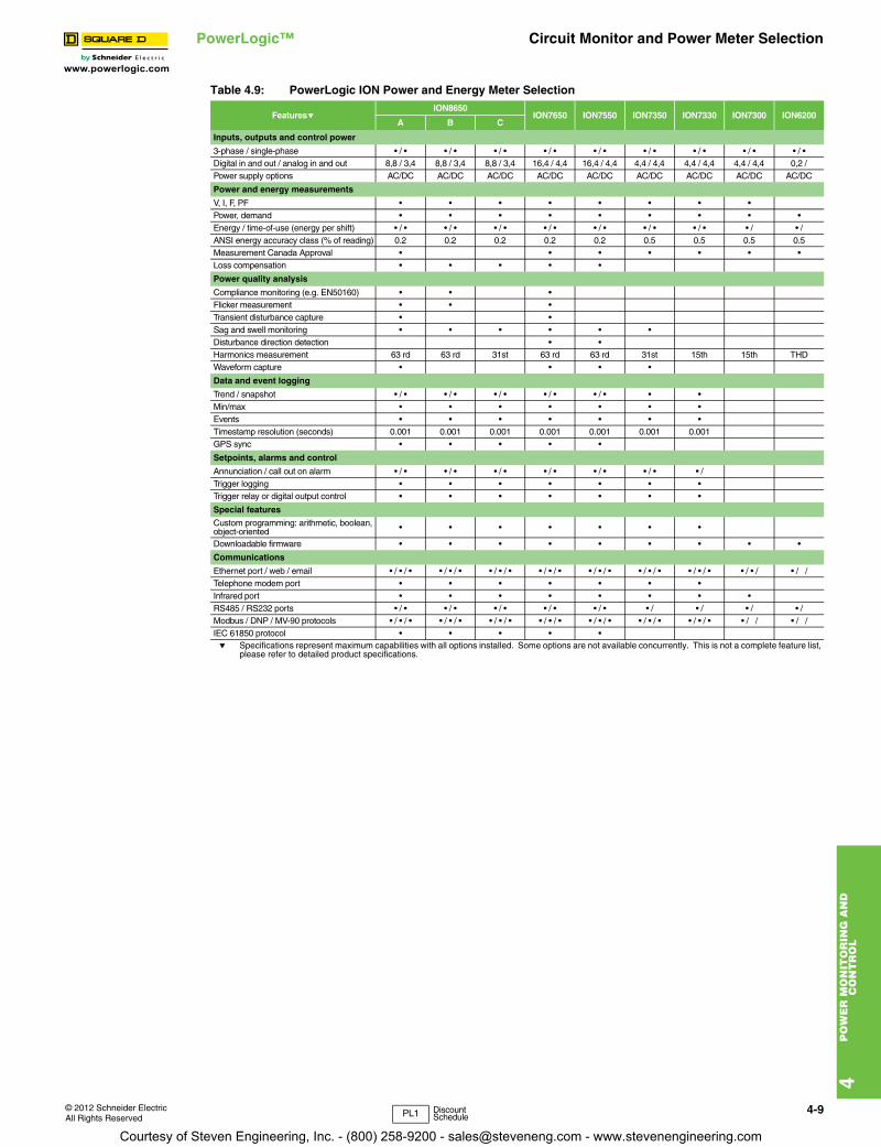
e Specifications represent maximum capabilities with all options installed. Some options are not available concurrently. This is not a complete feature list, please refer to detailed product specifications.
Table 4.9: PowerLogic ION Power and Energy Meter Selection
FeatureseION8650
ION7650 ION7550 ION7350 ION7330 ION7300 ION6200A B C
Inputs, outputs and control power
3-phase / single-phase • / • • / • • / • • / • • / • • / • • / • • / • • / • Digital in and out / analog in and out 8,8 / 3,4 8,8 / 3,4 8,8 / 3,4 16,4 / 4,4 16,4 / 4,4 4,4 / 4,4 4,4 / 4,4 4,4 / 4,4 0,2 /Power supply options AC/DC AC/DC AC/DC AC/DC AC/DC AC/DC AC/DC AC/DC AC/DC
Power and energy measurements
V, I, F, PF • • • • • • • • Power, demand • • • • • • • • • Energy / time-of-use (energy per shift) • / • • / • • / • • / • • / • • / • • / • • / • /ANSI energy accuracy class (% of reading) 0.2 0.2 0.2 0.2 0.2 0.5 0.5 0.5 0.5Measurement Canada Approval • • • • • • •Loss compensation • • • • •
Power quality analysis
Compliance monitoring (e.g. EN50160) • • •Flicker measurement • • •Transient disturbance capture • •Sag and swell monitoring • • • • • •Disturbance direction detection • •Harmonics measurement 63 rd 63 rd 31st 63 rd 63 rd 31st 15th 15th THDWaveform capture • • • •
Data and event logging
Trend / snapshot • / • • / • • / • • / • • / • • •Min/max • • • • • • •Events • • • • • • •Timestamp resolution (seconds) 0.001 0.001 0.001 0.001 0.001 0.001 0.001GPS sync • • • • •
Setpoints, alarms and control
Annunciation / call out on alarm • / • • / • • / • • / • • / • • / • • / Trigger logging • • • • • • •Trigger relay or digital output control • • • • • • •
Special features
Custom programming: arithmetic, boolean, object-oriented • • • • • • •
Downloadable firmware • • • • • • • • •
Communications
Ethernet port / web / email • / • / • • / • / • • / • / • • / • / • • / • / • • / • / • • / • / • • / • / • / /Telephone modem port • • • • • • •Infrared port • • • • • • • •RS485 / RS232 ports • / • • / • • / • • / • • / • • / • / • / • /Modbus / DNP / MV-90 protocols • / • / • • / • / • • / • / • • / • / • • / • / • • / • / • • / • / • • / / • / /IEC 61850 protocol • • • • •
PL1 DiscountSchedule
Courtesy of Steven Engineering, Inc. - (800) 258-9200 - [email protected] - www.stevenengineering.com
4-10 © 2012 Schneider ElectricAll Rights Reserved
www.powerlogic.com
4P
OW
ER
MO
NIT
OR
ING
AN
D
CO
NT
RO
L
PowerLogic™ Metering
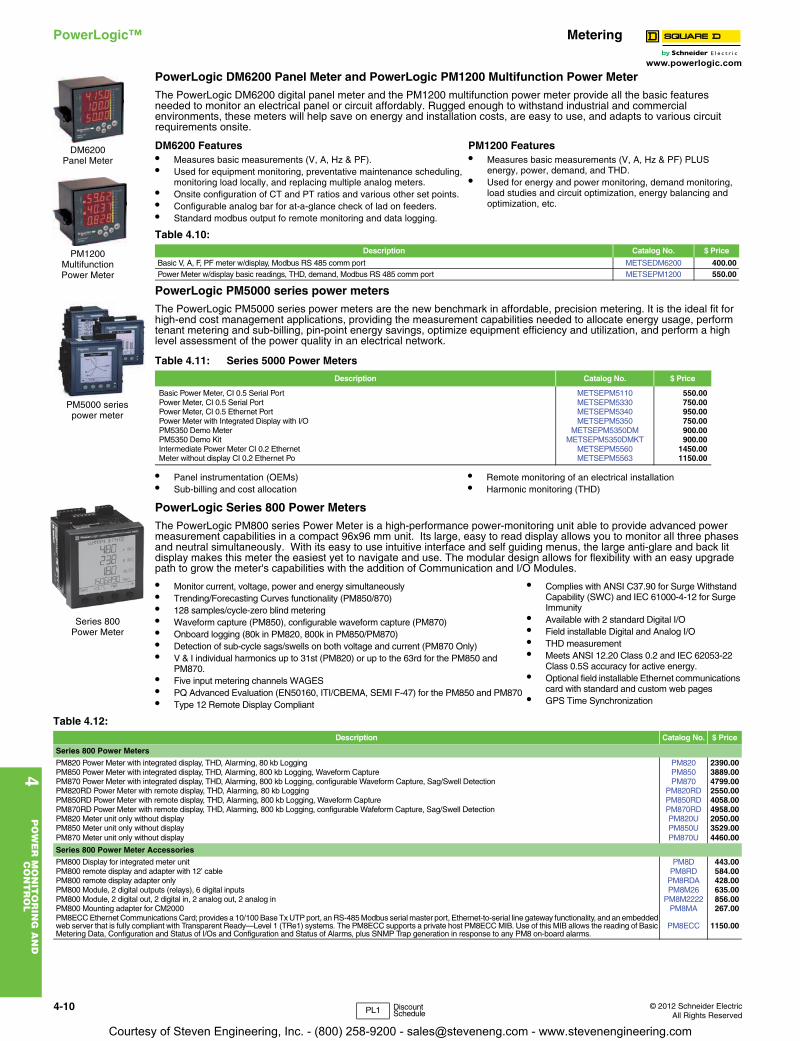
PowerLogic DM6200 Panel Meter and PowerLogic PM1200 Multifunction Power MeterThe PowerLogic DM6200 digital panel meter and the PM1200 multifunction power meter provide all the basic features needed to monitor an electrical panel or circuit affordably. Rugged enough to withstand industrial and commercial environments, these meters will help save on energy and installation costs, are easy to use, and adapts to various circuit requirements onsite.
PowerLogic PM5000 series power metersThe PowerLogic PM5000 series power meters are the new benchmark in affordable, precision metering. It is the ideal fit for high-end cost management applications, providing the measurement capabilities needed to allocate energy usage, perform tenant metering and sub-billing, pin-point energy savings, optimize equipment efficiency and utilization, and perform a high level assessment of the power quality in an electrical network.
PowerLogic Series 800 Power MetersThe PowerLogic PM800 series Power Meter is a high-performance power-monitoring unit able to provide advanced power measurement capabilities in a compact 96x96 mm unit. Its large, easy to read display allows you to monitor all three phases and neutral simultaneously. With its easy to use intuitive interface and self guiding menus, the large anti-glare and back lit display makes this meter the easiest yet to navigate and use. The modular design allows for flexibility with an easy upgrade path to grow the meter's capabilities with the addition of Communication and I/O Modules.
DM6200 Features• Measures basic measurements (V, A, Hz & PF).• Used for equipment monitoring, preventative maintenance scheduling,
monitoring load locally, and replacing multiple analog meters.• Onsite configuration of CT and PT ratios and various other set points.• Configurable analog bar for at-a-glance check of lad on feeders.• Standard modbus output fo remote monitoring and data logging.
PM1200 Features• Measures basic measurements (V, A, Hz & PF) PLUS
energy, power, demand, and THD.• Used for energy and power monitoring, demand monitoring,
load studies and circuit optimization, energy balancing and optimization, etc.
Table 4.10: Description Catalog No. $ Price
Basic V, A, F, PF meter w/display, Modbus RS 485 comm port METSEDM6200 400.00Power Meter w/display basic readings, THD, demand, Modbus RS 485 comm port METSEPM1200 550.00
Table 4.11: Series 5000 Power Meters
Description Catalog No. $ Price
Basic Power Meter, CI 0.5 Serial Port METSEPM5110 550.00Power Meter, CI 0.5 Serial Port METSEPM5330 750.00Power Meter, CI 0.5 Ethernet Port METSEPM5340 950.00Power Meter with Integrated Display with I/O METSEPM5350 750.00PM5350 Demo Meter METSEPM5350DM 900.00PM5350 Demo Kit METSEPM5350DMKT 900.00Intermediate Power Meter CI 0.2 Ethernet METSEPM5560 1450.00Meter without display CI 0.2 Ethernet Po METSEPM5563 1150.00
• Panel instrumentation (OEMs)• Sub-billing and cost allocation
• Remote monitoring of an electrical installation• Harmonic monitoring (THD)
• Monitor current, voltage, power and energy simultaneously• Trending/Forecasting Curves functionality (PM850/870)• 128 samples/cycle-zero blind metering• Waveform capture (PM850), configurable waveform capture (PM870)• Onboard logging (80k in PM820, 800k in PM850/PM870)• Detection of sub-cycle sags/swells on both voltage and current (PM870 Only)• V & I individual harmonics up to 31st (PM820) or up to the 63rd for the PM850 and
PM870.• Five input metering channels WAGES• PQ Advanced Evaluation (EN50160, ITI/CBEMA, SEMI F-47) for the PM850 and PM870• Type 12 Remote Display Compliant
• Complies with ANSI C37.90 for Surge Withstand Capability (SWC) and IEC 61000-4-12 for Surge Immunity
• Available with 2 standard Digital I/O• Field installable Digital and Analog I/O• THD measurement• Meets ANSI 12.20 Class 0.2 and IEC 62053-22
Class 0.5S accuracy for active energy.• Optional field installable Ethernet communications
card with standard and custom web pages• GPS Time Synchronization
PM5000 seriespower meter
DM6200 Panel Meter
PM1200 Multifunction Power Meter
Series 800 Power Meter
Table 4.12: Description Catalog No. $ Price
Series 800 Power Meters
PM820 Power Meter with integrated display, THD, Alarming, 80 kb Logging PM820 2390.00PM850 Power Meter with integrated display, THD, Alarming, 800 kb Logging, Waveform Capture PM850 3889.00PM870 Power Meter with integrated display, THD, Alarming, 800 kb Logging, configurable Waveform Capture, Sag/Swell Detection PM870 4799.00PM820RD Power Meter with remote display, THD, Alarming, 80 kb Logging PM820RD 2550.00PM850RD Power Meter with remote display, THD, Alarming, 800 kb Logging, Waveform Capture PM850RD 4058.00PM870RD Power Meter with remote display, THD, Alarming, 800 kb Logging, configurable Wafeform Capture, Sag/Swell Detection PM870RD 4958.00PM820 Meter unit only without display PM820U 2050.00PM850 Meter unit only without display PM850U 3529.00PM870 Meter unit only without display PM870U 4460.00
Series 800 Power Meter Accessories
PM800 Display for integrated meter unit PM8D 443.00PM800 remote display and adapter with 12’ cable PM8RD 584.00PM800 remote display adapter only PM8RDA 428.00PM800 Module, 2 digital outputs (relays), 6 digital inputs PM8M26 635.00PM800 Module, 2 digital out, 2 digital in, 2 analog out, 2 analog in PM8M2222 856.00PM800 Mounting adapter for CM2000 PM8MA 267.00PM8ECC Ethernet Communications Card; provides a 10/100 Base Tx UTP port, an RS-485 Modbus serial master port, Ethernet-to-serial line gateway functionality, and an embedded web server that is fully compliant with Transparent Ready—Level 1 (TRe1) systems. The PM8ECC supports a private host PM8ECC MIB. Use of this MIB allows the reading of Basic Metering Data, Configuration and Status of I/Os and Configuration and Status of Alarms, plus SNMP Trap generation in response to any PM8 on-board alarms.
PM8ECC 1150.00
PL1 Discount Schedule
Courtesy of Steven Engineering, Inc. - (800) 258-9200 - [email protected] - www.stevenengineering.com
www.powerlogic.com
4P
OW
ER
MO
NIT
OR
ING
AN
D
CO
NT
RO
L
© 2012 Schneider ElectricAll Rights Reserved
4-11
PowerLogic™ Metering
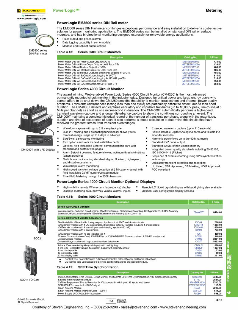
PowerLogic EM3500 series DIN Rail meterThe EM3500 series DIN Rail meter combinges exceptional performance and easy installation to deliver a cost-effective solution for power monitoring applications. The EM3500 series can be installed on standard DIN rail or surface mounted, and has bi-directional monitoring designed expressly for renewable energy applications.• Pulse output and phase alarms• Data logging capability in some models• Modbus and BACnet output options
PowerLogic Series 4000 Circuit MonitorThe award winning, Web-enabled PowerLogic Series 4000 Circuit Monitor (CM4250) is the most advanced permanently mounted circuit monitor in the industry today. Designed for critical power and large energy users who cannot afford to be shut down, the CM4250 provides the ability to monitor, troubleshoot and preempt power quality problems. Transients (disturbances lasting less than one cycle) are particularly difficult to detect, due to their short duration. The CM4000T detects and captures oscillatory and impulsive transients (up to 10,000V peak, line-to-line at 5 MHz per channel) as short as one microsecond in duration. The CM4000T automatically performs a high-speed transient waveform capture and a longer disturbance capture to show the conditions surrounding an event. The CM4000T maintains a complete historical record of the number of transients per phase, along with the magnitude, duration and time of occurrence of each. It also performs a stress calculation to determine the circuits that have received the greatest stress from transient overvoltages.
PowerLogic Series 4000 Circuit Monitor Optional Displays
a Contact your nearest Square D/Schneider Electric sales office for additional I/O options.b CM4250 is field upgradeable to provide additional features of specified module.
Table 4.13: Series 3500 Circuit Monitors
Description Catalog No. $ Price
Power Meter, DIN-rail, Pulse Output Only, for LVCTs METSEEM3502 433.00Power Meter, DIN-rail Pulse Output Only, for U018 Rope CTs METSEEM3502A 433.00Power Meter, DIN-rail Modbus Output for LVCTs METSEEM3550 486.00Power Meter, DIN-rail, Modbus Output, for U018 Rope CTs METSEEM3550A 486.00Power Meter, DIN-rail Modbus Output Bi-Directional, Logging for LVCTs METSEEM3555 486.00Power Meter, DIN-rail, BACnet Output, Logging for LVCTs METSEEM3560 614.00Power Meter, DIN-rail, BACnet Output, Logging for U018 Rope CTs METSEEM3560A 614.00Power Meter, DIN-rail, BACnet Output, for LVCTs METSEEM3561 658.00Power Meter, DIN-rail, BACnet Output, for U018 Rope CTs METSEEM3561A 658.00
• Waveform capture with up to 512 samples/cycle• Built-in Trending and Forecasting functionality allows you to
forecast energy usage up to 4 days in advance• Sag/Swell disturbance monitoring• Two option card slots for field installable cards• Optional field installable Ethernet communications card with
standard and custom web pages• Alarm Setpoint Learning feature allowing optimum threshold setting
(patent pending)• Multiple alarms including standard, digital, Boolean, high-speed,
and disturbance alarms• Waveshape alarm monitoring• High speed transient voltage detection at 5 MHz per channel with
field installable CVMT current/voltage module• True RMS Metering through the 255th harmonic
• Extended waveform capture (up to 110 seconds)• Field installable Digital/Analog I/O cards and flexible I/O
extender modules• Harmonic powerflows up to the 40th harmonic• Standard KYZ pulse output• Standard 32 MB of non-volatile memory• Integrated power quality standards including EN50160,
IEC 61000-4-15 (Flicker)• Sequence of events recording using GPS synchronization
technology• Oscillatory transient detection and recording• UL Listed, CSA Approved, CE Marking, NOM Approved,
FCC compliant
• High visibility remote VF (vacuum fluorescence) display• Displays metering data, min/max values, alarms, inputs
• Remote LC (liquid crystal) display with backlighting also available• Optional user configurable display screens
Table 4.14: Series 4000 Circuit Monitors
Description Catalog No. $ Price
Series 4000 Circuit Monitors
Instrumentation, On-board Data Logging, Waveform Capture, Disturbance Recording, Configurable I/O, 0.04% Accuracy CM4000T 8474.00Same as CM4250 plus Impulsive Transient Detection and Flicker (IEC 61000-4-15)
Series 4000 Circuit Monitor Accessories
Field installable I/O card with 3 relay outputs, 1 pulse output (KYZ) and 4 status inputs IOC44 796.00I/O Extender module with 4 DC status inputs, 2 DC digital outputs, 1 analog input and 1 analog output IOX2411 1253.00I/O Extender module with 4 status inputs and 4 analog inputs (4–20 mA) IOX0404 1650.00I/O Extender module with 8 status inputs IOX08 703.00
I/O Extender module with no pre-installed I/O a IOX 459.00Ethernet Communications Card; 100 MB Fiber or 10/100 MB UTP Ethernet port and 1 RS-485 master port ECC21 1948.00Current/Voltage module CVM42 2251.00Current/Voltage module with high speed transient detectionb CVMT 5393.00
4-line x 20—character liquid crystal display with backlighting CMDLC 688.004-line x 20—character vacuum fluorescent display with proximity sensor CMDVF 1207.004 foot display cable CAB4 53.0012 foot display cable CAB12 89.0030 foot display cable CAB30 161.00
Table 4.15: SER Time Synchronization
Description Catalog No. $ Price
PowerLogic Satellite Time System, Circuit Monitor and SEPAM GPS Time Synchronization, 100 microsecond accuracy STS3000 5348.00Satellite Time Reference Module STRM 2827.00CyTime Sequence of Events Recorder, 24 Vdc power / 24 Vdc inputs, 32 inputs, web server 9788SER3200 2700.00SER 3200 EZ connector for IRIG-B signal 9788EZCIRIGB 115.00Smart Antenna Module SAM 2292.00Smart Antenna Module Interface Cable—200 FT SAIF200 611.00Power Supply, 24DC/50W, DIN-mountable PS080 558.00
EM3500 seriesDIN Rail meter
CM4000T with VFD Display
ECC21
IOC44 I/O Card
PL1 Discount Schedule
Courtesy of Steven Engineering, Inc. - (800) 258-9200 - [email protected] - www.stevenengineering.com

4-12 © 2012 Schneider ElectricAll Rights Reserved
www.powerlogic.com
4P
OW
ER
MO
NIT
OR
ING
AN
D
CO
NT
RO
L
PowerLogic™ Submetering
Table 4.16: PowerLogic Circuit Monitor and Power Meter SelectionFeatures CM4000T PM870 PM850 PM820 PM5100 PM5300 PM5500 PM1200 DM6200
Inputs, outputs and control power
3-phase / single-phase • / • • / • • / • • / • • / • • / • • / • • / • • / •
Digital in and out / analog in and out 24 / 4 18 / 8 18 / 8 18 / 8 2/ 2/ 24 / 4 4/
Power supply options AC/DC AC/DC AC/DC AC/DC AC/DC AC/DC AC/DC AC/DC AC/DC
Power and energy measurements
V, I, F, PF • • • • • • • • •
Power, demand • • • • • • • • / •
Energy / energy per shift (time-of-use) • / • • / • • / • • / • • / • • / • • / • 0.2
Energy accuracy (%) 0.2 0.2 0.2 0.2 0.5 0.5 0.2 • / •
Standards compliance to ANSI / IEC • / • • / • • / • • / • • / • • / • • / • •
Power quality analysis
Compliance monitoring (e.g. EN50160) • • •
Flicker measurement •
High-speed transient disturbance capture (200 ns) •
Transient disturbance capture • sag/swell
Disturbance direction detection •
Sag/swell monitoring • •
Harmonics measurement • • • • THD THD •
Uptime (number of 9's) calculation •
Waveform capture • • •
Waveshape alarm •
Data and event logging
Trend / billing • / • / • • / • / •
Minimum and maximum • • • • •
Events / maintenance • / • • / • / • / • /
Timestamp resolution (seconds) 0.001 1 1 1
GPS sync • • • •
Setpoints, alarms and control
Annunciation / call out on alarm • / • • / • / • / • / /
Trigger logging • • • • •
Trigger relay or digital ouput control • • • • •
Special features
Custom programming: arithmetic, boolean • •
Downloadable firmware • • • • • • •
Communications
Ethernet port / web / email • / • / • • / • / • • / • / • • / • / • / / • / • / •
RS485 / RS232 ports • / • • / • • / • • / • • / • / • • •
Modbus protocol • • • • • • • • •
PL1 Discount Schedule
Courtesy of Steven Engineering, Inc. - (800) 258-9200 - [email protected] - www.stevenengineering.com

www.powerlogic.com
4P
OW
ER
MO
NIT
OR
ING
AN
D
CO
NT
RO
L
© 2012 Schneider ElectricAll Rights Reserved
4-13
PowerLogic™ Submetering
PowerLogic SubmeteringIn today's increasingly competitive commercial property market, attracting and retaining high-quality, long-term tenants by offering exceptional value is the primary goal. Balancing these premium services and reliable infrastructure vs. the financial exposure to volatile utility costs is the challenge.Minimizing energy costs requires information on how energy usage translates into money spent. PowerLogic energy sub-metering systems are specifically engineered to address the measurement, verification and billing needs of multi-tenant properties.
• Residential high-rise and low-rise• Campuses• Shopping centers• Malls / food courts• Offices• Commercial buildingsPowerLogic energy management and metering systems are ideal for multi-tenant buildings providing:• Metering & Verification tools to assure
compliance to Energy Policy Act 2005• Integrated approach from simple energy
allocation requirements to high-end power quality
• Monitor energy usage and efficiency to accurately recover the costs while providing tenants with energy and a reliable infrastructure
• Implement energy efficiency initiatives essential to obtaining LEED certification
PowerLogic E5600 Socket MeterThe E5600 is a cost effective socket meter that combines high accuracy, superior quality and wide-ranging capability in a device that is simple to install. The PowerLogic E5600 socket meter can help reduce electrical costs, increase property values and attract good tenants by providing the information needed to manage energy costs. Track and allocate costs by circuit or suite, accurately bill tenants for energy used, and verify energy conservation efforts. It is a foundational component for LEED and Energy Star certification as a part of green buildings. Green buildings enjoy higher tenant retention, higher tenant quality, and recognition by the community while typically allowing property managers to charge more for rent.Unlike traditional sub-metering solutions, which must be manually read or may lack software for effective sub-billing or comprehensive energy management, the PowerLogic E5600 enables businesses to utilize their existing S-based socket infrastructure with alow-cost meter that is part of an end-to-end solution for tenant sub-metering.• Real, reactive, and apparent energy values.• Onboard interval data logging (load profiles).• Revenue grade accuracy – ANSI C12.20 0.2% / 0.5%.• Automatic configuration of service type and voltage.• Onboard diagnostics continually monitors for equipment failures, improper installation wiring, poor
load conditions, poor power quality conditions and tampering.• S-base meter socket compatible.
Table 4.17: Description Catalog No. $ Price
Form 2S, Single-Phase, Class 200, S Based Meter E5600020SQD 960.00Form 9S, 3-Phase, Class 20, S Based Meter E5600090SQD 1080.00Form 12S, 3-Phase, Class 200, S Based Meter E5600120SQD 1080.00Form 16S, 3-Phase, Class 200, S Based Meter E5600160SQD 1080.00Form 36S, 3-Phase, Class 20, S Based Meter E5600360SQD 1080.00Form 45S, 3-Phase, Class 20, S Based Meter E5600450SQD 1080.00Optional USB Optical Communications Probe OPTICALPROBEUSB 719.00
PowerLogic E5600 Socket Meter
PL1 Discount Schedule
Courtesy of Steven Engineering, Inc. - (800) 258-9200 - [email protected] - www.stevenengineering.com
4-14
4P
OW
ER
MO
NIT
OR
ING
AN
D
CO
NT
RO
L
www.powerlogic.com
© 2012 Schneider ElectricAll Rights Reserved
PowerLogic™ Submetering
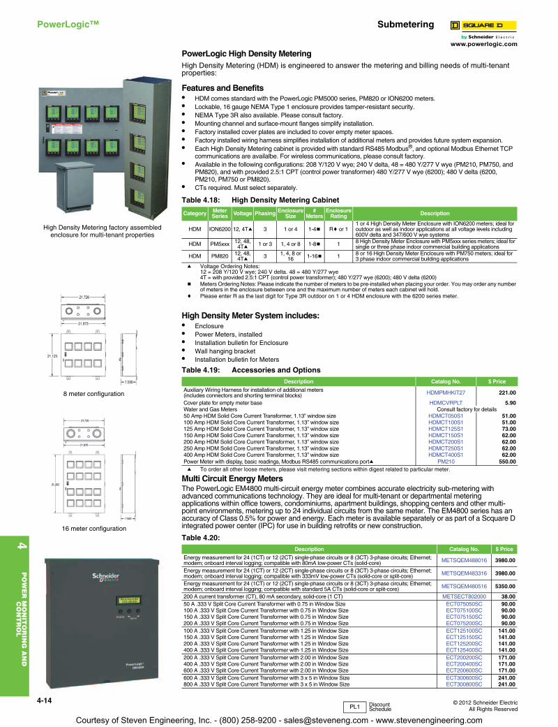
PowerLogic High Density MeteringHigh Density Metering (HDM) is engineered to answer the metering and billing needs of multi-tenant properties:
Features and Benefits• HDM comes standard with the PowerLogic PM5000 series, PM820 or ION6200 meters.• Lockable, 16 gauge NEMA Type 1 enclosure provides tamper-resistant security.• NEMA Type 3R also available. Please consult factory.• Mounting channel and surface-mount flanges simplify installation.• Factory installed cover plates are included to cover empty meter spaces.• Factory installed wiring harness simplifies installation of additional meters and provides future system expansion.• Each High Density Metering cabinet is provided with standard RS485 Modbus®, and optional Modbus Ethernet TCP
communications are availalbe. For wireless communications, please consult factory. • Available in the following configurations: 208 Y/120 V wye; 240 V delta, 48 = 480 Y/277 V wye (PM210, PM750, and
PM820), and with provided 2.5:1 CPT (control power transformer) 480 Y/277 V wye (6200); 480 V delta (6200, PM210, PM750 or PM820).
• CTs required. Must select separately.
a Voltage Ordering Notes:12 = 208 Y/120 V wye; 240 V delta. 48 = 480 Y/277 wye4T = with provided 2.5:1 CPT (control power transformer); 480 Y/277 wye (6200); 480 V delta (6200)
b Meters Ordering Notes: Please indicate the number of meters to be pre-installed when placing your order. You may order any number of meters in the enclosure between one and the maximum number of meters each cabinet will hold.
c Please enter R as the last digit for Type 3R outdoor on 1 or 4 HDM enclosure with the 6200 series meter.
High Density Meter System includes:• Enclosure• Power Meters, installed• Installation bulletin for Enclosure• Wall hanging bracket• Installation bulletin for Meters
a To order all other loose meters, please visit metering sections within digest related to particular meter.
Multi Circuit Energy MetersThe PowerLogic EM4800 multi-circuit energy meter combines accurate electricity sub-metering with advanced communications technology. They are ideal for multi-tenant or departmental metering applications within office towers, condominiums, apartment buildings, shopping centers and other multi-point environments, metering up to 24 individual circuits from the same meter. The EM4800 series has an accuracy of Class 0.5% for power and energy. Each meter is available separately or as part of a Scquare D integrated power center (IPC) for use in building retrofits or new construction.
Table 4.18: High Density Metering Cabinet
Category Meter Series Voltage Phasing Enclosure
Size#
MetersEnclosure
Rating Description
HDM ION6200 12, 4Ta 3 1 or 4 1-4b Rc or 11 or 4 High Density Meter Enclosure with ION6200 meters; ideal for outdoor as well as indoor applications at all voltage levels including 600V delta and 347/600 V wye systems
HDM PM5xxx 12, 48, 4Ta 1 or 3 1, 4 or 8 1-8b 1 8 High Density Meter Enclosure with PM5xxx series meters; ideal for
single or three phase indoor commercial building applications
HDM PM820 12, 48, 4Ta 3 1, 4, 8 or
16 1-16b 1 8 or 16 High Density Meter Enclosure with PM750 meters; ideal for 3 phase indoor commercial building applications
Table 4.19: Accessories and OptionsDescription Catalog No. $ Price
Auxiliary Wiring Harness for installation of additional meters(includes connectors and shorting terminal blocks) HDMPMHKIT27 221.00
Cover plate for empty meter base HDMCVRPLT 5.90Water and Gas Meters Consult factory for details50 Amp HDM Solid Core Current Transformer, 1.13” window size HDMCT050S1 51.00100 Amp HDM Solid Core Current Transformer, 1.13” window size HDMCT100S1 51.00125 Amp HDM Solid Core Current Transformer, 1.13” window size HDMCT125S1 73.00150 Amp HDM Solid Core Current Transformer, 1.13” window size HDMCT150S1 62.00200 Amp HDM Solid Core Current Transformer, 1.13” window size HDMCT200S1 62.00250 Amp HDM Solid Core Current Transformer, 1.13” window size HDMCT250S1 62.00400 Amp HDM Solid Core Current Transformer, 1.13” window size HDMCT400S1 62.00Power Meter with display, basic readings, Modbus RS485 communications porta PM210 550.00
Table 4.20: Description Catalog No. $ Price
Energy measurement for 24 (1CT) or 12 (2CT) single-phase circuits or 8 (3CT) 3-phase circuits; Ethernet; modem; onboard interval logging; compatible with 80mA low-power CTs (solid-core) METSQEM488016 3980.00
Energy measurement for 24 (1CT) or 12 (2CT) single-phase circuits or 8 (3CT) 3-phase circuits; Ethernet; modem; onboard interval logging; compatible with 333mV low-power CTs (solid-core or split-core) METSQEM483316 3980.00
Energy measurement for 24 (1CT) or 12 (2CT) single-phase circuits or 8 (3CT) 3-phase circuits; Ethernet; modem; onboard interval logging; compatible with standard 5A CTs (solid-core or split-core) METSQEM480516 5350.00
200 A current transformer (CT), 80 mA secondary, solid-core (1 CT) METSECT802000 38.0050 A .333 V Split Core Current Transformer with 0.75 in Window Size ECT075050SC 90.00100 A .333 V Split Core Current Transformer with 0.75 in Window Size ECT075100SC 90.00150 A .333 V Split Core Current Transformer with 0.75 in Window Size ECT075150SC 90.00200 A .333 V Split Core Current Transformer with 0.75 in Window Size ECT075200SC 90.00100 A .333 V Split Core Current Transformer with 1.25 in Window Size ECT125100SC 141.00150 A .333 V Split Core Current Transformer with 1.25 in Window Size ECT125150SC 141.00200 A .333 V Split Core Current Transformer with 1.25 in Window Size ECT125200SC 141.00400 A .333 V Split Core Current Transformer with 1.25 in Window Size ECT125400SC 141.00200 A .333 V Split Core Current Transformer with 2.00 in Window Size ECT200200SC 171.00400 A .333 V Split Core Current Transformer with 2.00 in Window Size ECT200400SC 171.00600 A .333 V Split Core Current Transformer with 2.00 in Window Size ECT200600SC 171.00600 A .333 V Split Core Current Transformer with 3 x 5 in Window Size ECT300600SC 241.00800 A .333 V Split Core Current Transformer with 3 x 5 in Window Size ECT300800SC 241.00
High Density Metering factory assembled enclosure for multi-tenant properties
16 meter configuration
8 meter configuration
PL1 Discount Schedule
Courtesy of Steven Engineering, Inc. - (800) 258-9200 - [email protected] - www.stevenengineering.com
www.powerlogic.com
4P
OW
ER
MO
NIT
OR
ING
AN
D
CO
NT
RO
L
© 2012 Schneider ElectricAll Rights Reserved
4-15
PowerLogic™ Submetering
Energy Meter
Note: CT quantity and amperage must match meter model. Total of combined loads must not exceed rating of meter. All additional CTs shipped with 6 ft. white and black color-coded wire leads.
a Energy Meter communication board (EMCB) can be used with all models of the Energy Meter. Order one EMCB for each Energy Meter where either kW demand and/or communication is specified.
b See Handout / Instruction Bulletin for derating properties.
Note: Max. Voltage without additional insulation 600 Vac. Do not apply 600 V Class current transformers to circuits having a phase-to-phase voltage greater than 600 V, unless adequate additional insulation is applied between the primary conductor and the current transformers. Square D assumes no responsibility for damage of equipment or personal injury caused by transformers operated on circuits above their published ratings.
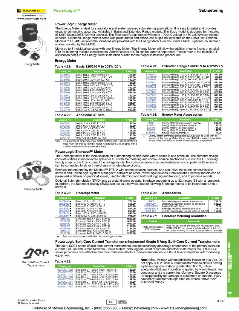
PowerLogic Energy MeterThe Energy Meter is ideal for stand-alone and systems-based submetering applications. It is easy to install and provides exceptional metering accuracy. Available in Basic and Extended Range models. The Basic model is designed for metering of 120/240 and 208Y/120 volt services. The Extended Range model will meter 120/240 volt up to 480 volt Wye connected services. Extended Range meters come with pulse output and phase loss output not available on the Basic unit. Optional Modbus™ RS-485 serial communications are provided with the Energy Meter Comms Board, EMCB. Optional kW demand is also provided by the EMCB.Meter up to 3 individual services with one Energy Meter. The Energy Meter will allow the addition of up to 3 sets of parallel CTs for metering multiple electric loads. Additional sets of CTs can be ordered separately. Please refer to the multiple CT application notes in the Energy Meter instruction bulletin for the proper installation procedures.
Energy MeterTable 4.21: Basic 120/240 V to 208Y/120 V
Catalog No. Description $ Price
EMB1010 Basic 100 A, .518"x1.28" ID, 1 CT 426.00EMB1021 Basic 200 A, 0.75” x 1.10” ID, 1 CT 440.00EMB1032 Basic 300 A, .90"x1.90" ID, 1 CT 482.00EMB2010 Basic 100 A, .518"x1.28" ID, 2 CTs 438.00EMB2021 Basic 200 A, 0.75” x 1.10” ID, 2 CTs 464.00EMB2032 Basic 300 A, .90"x1.90" ID, 2 CTs 480.00EMB2043 Basic 400 A, 2.45"x2.89" ID, 2 CTs 505.00EMB2083 Basic 800 A, 2.45"x2.89" ID, 2 CTs 517.00EMB3010 Basic 100 A, .518"x1.28" ID, 3 CTs 750.00EMB3021 Basic 200 A, 0.75” x 1.10” ID, 3 CTs 766.00EMB3032 Basic 300 A, .90"x1.90" ID, 3 CTs 799.00EMB3043 Basic 400 A, 2.45"x2.89" ID, 3 CTs 825.00EMB3083 Basic 800 A, 2.45"x2.89" ID, 3 CTs 855.00EMB3084 Basic 800 A, 2.45"x5.50" ID, 3 CTs 903.00EMB3164 Basic 1600 A, 2.45"x5.50" ID, 3 CTs 903.00
Table 4.22: Additional CT SetsCatalog No. Description $ Price
EMCT010 100 A, .518” x 1.28” ID, 1 CT 92.00EMCT021 200 A, 0.75” x 1.10” ID, 1 CT 99.00EMCT032 300 A, .90” x 1.90” ID, 1 CT 106.00EMCT043 400 A, 2.45” x 2.89” ID, 1 CT 106.00EMCT083 800 A, 2.45” x 2.89” ID, 1 CT 123.00EMCT084 800 A, 2.45” x 5.50” ID, 1 CT 130.00EMCT164 1600 A, 2.45” x 5.50” ID, 1 CT 130.00
Table 4.23: Extended Range 120/240 V to 480Y/277 VCatalog No. Description $ Price
EME1010 Extended Range 100 A, .518"x1.28" ID, 1 CT 471.00EME1021 Extended Range 200 A, 0.75” x 1.10” ID, 1 CT 483.00EME1032 Extended Range 300 A, .90"x1.90" ID, 1 CT 518.00EME2010 Extended Range 100 A, n.518"x1.28" ID, 2 CTs 511.00EME2021 Extended Range 200 A, 0.75” x 1.10” ID, 2 CTs 536.00EME2032 Extended Range 300 A, .90"x1.90" ID, 2 CTs 550.00EME2043 Extended Range 400 A, 2.45"x2.89" ID, 2 CTs 567.00EME2083 Extended Range 800 A, 2.45"x2.89" ID, 2 CTs 585.00EME3010 Extended Range 100 A, .518"x1.28" ID, 3 CTs 811.00EME3021 Extended Range 200 A, 0.75” x 1.10” ID, 3 CTs 829.00EME3032 Extended Range 300 A, .90"x1.90" ID, 3 CTs 864.00EME3043 Extended Range 400 A, 2.45"x2.89" ID, 3 CTs 880.00EME3083 Extended Range 800 A, 2.45"x2.89" ID, 3 CTs 921.00EME3084 Extended Range 800 A, 2.45"x5.50" ID, 3 CTs 971.00EME3164 Extended Range 1600 A, 2.45"x5.50" ID, 3 CTs 971.00
Table 4.24: Energy Meter AccessoriesCatalog No. Description $ Price
EMCB Energy Meter Communication Boarda 267.00EMFP1 Energy Meter Fuse Pack, Set of 1 47.00EMFP2 Energy Meter Fuse Pack, Set of 2 94.00EMFP3 Energy Meter Fuse Pack, Set of 3 142.00
EMBOND Energy Meter Bonding Kit 117.00
PowerLogic Enercept™ MeterThe Enercept Meter is the ideal solution for submetering electric loads where space is at a premium. The compact design consists of three interconnected split-core CTs with the metering and communication electronics built into the CT housing. Simply snap on the CTs, connect the voltage inputs, the communication lines, and installation is complete. Both versions can be connected to either three-phase or single-phase circuits. Enercept meters employ the Modbus™ RTU 2-wire communication protocol, and can utilize the same communication network and PowerLogic System Manager™ software as other PowerLogic devices. Data from the Enercept meters can be presented in tabular or graphical format, used for alarming and historical logging and trending, and to produce reports. Optional Submeter display (SMD) acts as a stand-alone operator interface supporting up to 32 meters (63 with a repeater). In addition, the Submeter display (SMD) can act as a network adapter allowing Enercept meters to be incorporated into a network.
Enercept MeterTable 4.25: Enercept Meter
Catalog No. Description $ Price
3020B012b Basic 100 A, 1.25" x 1.51" ID 776.003020B032b Basic 300 A, 1.25" x 1.51" ID 800.003020B043b Basic 400 A, 2.45" x 2.89" ID 823.003020B083b Basic 800 A, 2.45" x 2.89" ID 847.003020B084b Basic 800 A, 2.45" x 5.50" ID 869.003020B164b Basic 1600 A, 2.45" x 5.50" ID 893.003020B244b Basic 2400 A, 2.45" x 5.50" ID 916.003020E012 Enhanced 100 A, 1.25" x 1.51" ID 1035.003020E032 Enhanced 300 A, 1.25" x 1.51" ID 1066.003020E043 Enhanced 400 A, 2.45" x 2.89" ID 1097.003020E083 Enhanced 800 A, 2.45" x 2.89" ID 1128.003020E084 Enhanced 800 A, 2.45" x 5.50" ID 1159.003020E164 Enhanced 1600 A, 2.45" x 5.50" ID 1190.003020E244 Enhanced 2400 A, 2.45" x 5.50" ID 1221.00
Table 4.26: AccessoriesCatalog No. Description $ Price
SMD Submeter display mounted in enclosure 725.00SMD OPN Open style submeter display, no enclosure 595.00
30502W485C 2-Wire 232–485 Conv 78.003050EMBK-3 Enercept Mounting Brackets (Set of 3) 75.00
3090PS24 24 Vdc Power Supply (for use with EDI or ENA) 157.00
Table 4.27: Enercept Metering Quantities
Basicb Enhanced•
kWh, energy usage kW, real power
kWh, kW per phase and total, min kW, max kW, kWd, kVAR, kVA, PF per phase and total voltage- V, L-L, L-N per phase and avg. Current - A, per phase and average
PowerLogic Split Core Current Transformers-Instrument Grade 5 Amp Split-Core Current TransformersThe 3090 SCCT series of split-core current transformers provide secondary amperage proportional to the primary (sensed) current. For use with Circuit Monitors, Power Meters, data loggers, chart recorders and other instruments the 3090 SCCT series provides a cost-effective means to transform electrical service amperages to a 0–5A level compatible with monitoring equipment.
SA Split-Core Current Transformers
Table 4.28: Catalog No. Description $ Price
3090SCCT022 Split Core CT—200 A (sz.2): 1.25" x 1.51 120.003090SCCT032 Split Core CT—300 A (sz.2): 1.25" x 1.51 120.003090SCCT043 Split Core CT—400 A (sz.3): 2.45" x 2.89 129.003090SCCT063 Split Core CT—600 A (sz.3): 2.45" x 2.89 129.003090SCCT083 Split Core CT—800 A (sz.3): 2.45" x 2.89 129.003090SCCT084 Split Core CT—800 A (sz.4): 2.45" x 5.05 137.003090SCCT124 Split Core CT—1200 A (sz.4): 2.45" x 5.50 160.003090SCCT164 Split Core CT—1600 A (sz.4): 2.45" x 5.50 165.00
PL1 DiscountSchedule
Courtesy of Steven Engineering, Inc. - (800) 258-9200 - [email protected] - www.stevenengineering.com
4-16 © 2012 Schneider ElectricAll Rights Reserved
www.powerlogic.com
4P
OW
ER
MO
NIT
OR
ING
AN
D
CO
NT
RO
L
PowerLogic™ SubmeteringClass 3030
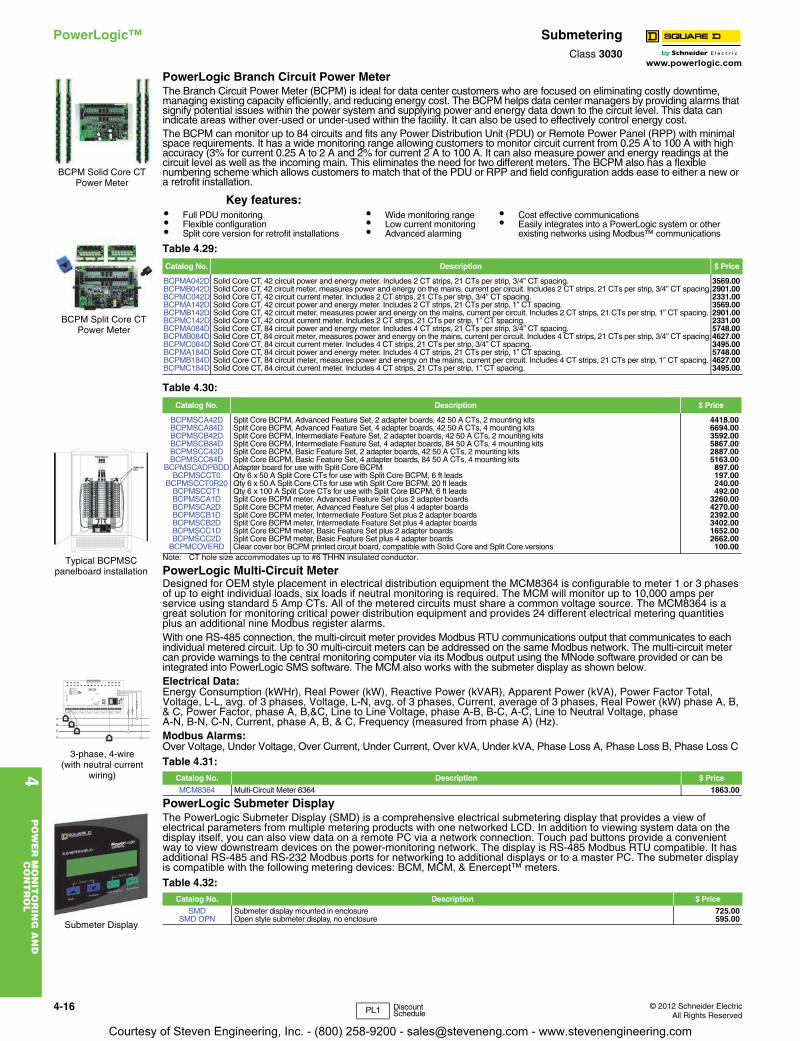
PowerLogic Branch Circuit Power MeterThe Branch Circuit Power Meter (BCPM) is ideal for data center customers who are focused on eliminating costly downtime, managing existing capacity efficiently, and reducing energy cost. The BCPM helps data center managers by providing alarms that signify potential issues within the power system and supplying power and energy data down to the circuit level. This data can indicate areas wither over-used or under-used within the facility. It can also be used to effectively control energy cost.The BCPM can monitor up to 84 circuits and fits any Power Distribution Unit (PDU) or Remote Power Panel (RPP) with minimal space requirements. It has a wide monitoring range allowing customers to monitor circuit current from 0.25 A to 100 A with high accuracy (3% for current 0.25 A to 2 A and 2% for current 2 A to 100 A. It can also measure power and energy readings at the circuit level as well as the incoming main. This eliminates the need for two different meters. The BCPM also has a flexible numbering scheme which allows customers to match that of the PDU or RPP and field configuration adds ease to either a new or a retrofit installation.
Note: CT hole size accommodates up to #6 THHN insulated conductor.
PowerLogic Multi-Circuit MeterDesigned for OEM style placement in electrical distribution equipment the MCM8364 is configurable to meter 1 or 3 phases of up to eight individual loads, six loads if neutral monitoring is required. The MCM will monitor up to 10,000 amps per service using standard 5 Amp CTs. All of the metered circuits must share a common voltage source. The MCM8364 is a great solution for monitoring critical power distribution equipment and provides 24 different electrical metering quantities plus an additional nine Modbus register alarms. With one RS-485 connection, the multi-circuit meter provides Modbus RTU communications output that communicates to each individual metered circuit. Up to 30 multi-circuit meters can be addressed on the same Modbus network. The multi-circuit meter can provide warnings to the central monitoring computer via its Modbus output using the MNode software provided or can be integrated into PowerLogic SMS software. The MCM also works with the submeter display as shown below. Electrical Data:Energy Consumption (kWHr), Real Power (kW), Reactive Power (kVAR), Apparent Power (kVA), Power Factor Total, Voltage, L-L, avg. of 3 phases, Voltage, L-N, avg. of 3 phases, Current, average of 3 phases, Real Power (kW) phase A, B, & C, Power Factor, phase A, B,&C, Line to Line Voltage, phase A-B, B-C, A-C, Line to Neutral Voltage, phaseA-N, B-N, C-N, Current, phase A, B, & C, Frequency (measured from phase A) (Hz).Modbus Alarms:Over Voltage, Under Voltage, Over Current, Under Current, Over kVA, Under kVA, Phase Loss A, Phase Loss B, Phase Loss C
PowerLogic Submeter DisplayThe PowerLogic Submeter Display (SMD) is a comprehensive electrical submetering display that provides a view of electrical parameters from multiple metering products with one networked LCD. In addition to viewing system data on the display itself, you can also view data on a remote PC via a network connection. Touch pad buttons provide a convenient way to view downstream devices on the power-monitoring network. The display is RS-485 Modbus RTU compatible. It has additional RS-485 and RS-232 Modbus ports for networking to additional displays or to a master PC. The submeter display is compatible with the following metering devices: BCM, MCM, & Enercept™ meters.
Key features:• Full PDU monitoring• Flexible configuration• Split core version for retrofit installations
• Wide monitoring range• Low current monitoring• Advanced alarming
• Cost effective communications• Easily integrates into a PowerLogic system or other
existing networks using Modbus™ communications
Table 4.29:
Catalog No. Description $ Price
BCPMA042D Solid Core CT, 42 circuit power and energy meter. Includes 2 CT strips, 21 CTs per strip, 3/4” CT spacing. 3569.00BCPMB042D Solid Core CT, 42 circuit meter, measures power and energy on the mains, current per circuit. Includes 2 CT strips, 21 CTs per strip, 3/4” CT spacing.2901.00BCPMC042D Solid Core CT, 42 circuit current meter. Includes 2 CT strips, 21 CTs per strip, 3/4” CT spacing. 2331.00BCPMA142D Solid Core CT, 42 circuit power and energy meter. Includes 2 CT strips, 21 CTs per strip, 1” CT spacing. 3569.00BCPMB142D Solid Core CT, 42 circuit meter, measures power and energy on the mains, current per circuit. Includes 2 CT strips, 21 CTs per strip, 1” CT spacing. 2901.00BCPMC142D Solid Core CT, 42 circuit current meter. Includes 2 CT strips, 21 CTs per strip, 1” CT spacing. 2331.00BCPMA084D Solid Core CT, 84 circuit power and energy meter. Includes 4 CT strips, 21 CTs per strip, 3/4” CT spacing. 5748.00BCPMB084D Solid Core CT, 84 circuit meter, measures power and energy on the mains, current per circuit. Includes 4 CT strips, 21 CTs per strip, 3/4” CT spacing.4627.00BCPMC084D Solid Core CT, 84 circuit current meter. Includes 4 CT strips, 21 CTs per strip, 3/4” CT spacing. 3495.00BCPMA184D Solid Core CT, 84 circuit power and energy meter. Includes 4 CT strips, 21 CTs per strip, 1” CT spacing. 5748.00BCPMB184D Solid Core CT, 84 circuit meter, measures power and energy on the mains, current per circuit. Includes 4 CT strips, 21 CTs per strip, 1” CT spacing. 4627.00BCPMC184D Solid Core CT, 84 circuit current meter. Includes 4 CT strips, 21 CTs per strip, 1” CT spacing. 3495.00
Table 4.30:
Catalog No. Description $ Price
BCPMSCA42D Split Core BCPM, Advanced Feature Set, 2 adapter boards, 42 50 A CTs, 2 mounting kits 4418.00BCPMSCA84D Split Core BCPM, Advanced Feature Set, 4 adapter boards, 42 50 A CTs, 4 mounting kits 6694.00BCPMSCB42D Split Core BCPM, Intermediate Feature Set, 2 adapter boards, 42 50 A CTs, 2 mounting kits 3592.00BCPMSCB84D Split Core BCPM, Intermediate Feature Set, 4 adapter boards, 84 50 A CTs, 4 mounting kits 5867.00BCPMSCC42D Split Core BCPM, Basic Feature Set, 2 adapter boards, 42 50 A CTs, 2 mounting kits 2887.00BCPMSCC84D Split Core BCPM, Basic Feature Set, 4 adapter boards, 84 50 A CTs, 4 mounting kits 5163.00
BCPMSCADPBDD Adapter board for use with Split Core BCPM 897.00BCPMSCCT0 Qty 6 x 50 A Split Core CTs for use with Split Core BCPM, 6 ft leads 197.00
BCPMSCCT0R20 Qty 6 x 50 A Split Core CTs for use wtih Split Core BCPM, 20 ft leads 240.00BCPMSCCT1 Qty 6 x 100 A Split Core CTs for use with Split Core BCPM, 6 ft leads 492.00BCPMSCA1D Split Core BCPM meter, Advanced Feature Set plus 2 adapter boards 3260.00BCPMSCA2D Split Core BCPM meter, Advanced Feature Set plus 4 adapter boards 4270.00BCPMSCB1D Split Core BCPM meter, Intermediate Feature Set plus 2 adapter boards 2392.00BCPMSCB2D Split Core BCPM meter, Intermediate Feature Set plus 4 adapter boards 3402.00BCPMSCC1D Split Core BCPM meter, Basic Feature Set plus 2 adapter boards 1652.00BCPMSCC2D Split Core BCPM meter, Basic Feature Set plus 4 adapter boards 2662.00
BCPMCOVERD Clear cover bor BCPM printed circuit board, compatible with Solid Core and Split Core versions 100.00
Table 4.31: Catalog No. Description $ Price
MCM8364 Multi-Circuit Meter 8364 1863.00
Table 4.32: Catalog No. Description $ Price
SMD Submeter display mounted in enclosure 725.00SMD OPN Open style submeter display, no enclosure 595.00
BCPM Solid Core CT Power Meter
BCPM Split Core CT Power Meter
3-phase, 4-wire(with neutral current
wiring)
Typical BCPMSCpanelboard installation
Submeter Display
PL1 Discount Schedule
Courtesy of Steven Engineering, Inc. - (800) 258-9200 - [email protected] - www.stevenengineering.com

www.powerlogic.com
4P
OW
ER
MO
NIT
OR
ING
AN
D
CO
NT
RO
L
© 2012 Schneider ElectricAll Rights Reserved
4-17
PowerLogic™ Data Logger
Energy Server Com’X200 Data Logger
Energy Server Com’X 200 surpasses conventional data loggers by incorporating multiple capabilities into one compact device. It is possible to install the Energy Server Com’X 200, plug in the metering devices, and test and commission the data acquisition in less than 1 hour. A tested, validated, and document architecture, the Energy Server Com’X 200 logs all the essential WAGES and environmental readings. It is enriched with a broad range of upstream and downstream data feeds. Ethernet and Wi-Fi ready, it leverages on the building’s existing IT infrastructure to reduce cost. Its GPRS capability makes it ideal for sites with no access to IT networks. Configuration and commissioning is made easy by automatic device detection, and IP address setting and allocation. No additional software is needed for the intuitive, web-based configuration pages. A device library enables quick reference for Modbus connected devices and pre-configured parameters. Configuration via Wi-Fi lets technicians use tablets or notebooks to work comfortably away from switchboard rooms.
Table 4.33: Energy Server Com’X200Description Catalog Number
Com’X200 Ethernet data logger EBX 200Wi-Fi USB stick EBXA-USB-WiFiGPRS modem with SIM card EBXA-CPRS-SIMGPRS modem without SIM card EBXA-CPRSExternal GPRS antenna EBXA-ANT-SIM
CommX200 Data Logger
Courtesy of Steven Engineering, Inc. - (800) 258-9200 - [email protected] - www.stevenengineering.com
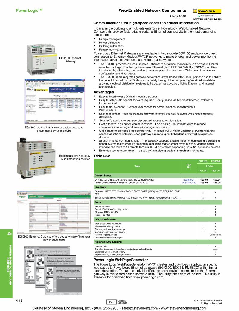
www.powerlogic.com
4P
OW
ER
MO
NIT
OR
ING
AN
D
CO
NT
RO
L
4-18 © 2012 Schneider ElectricAll Rights Reserved
PowerLogic™ Web-Enabled Network ComponentsClass 3030
Communications for high-speed access to critical information
From a single building to a multi-site enterprise, PowerLogic Web-Enabled Network Components provide fast, reliable serial to Ethernet connectivity in the most demanding applications:• Energy management • Power distribution • Building automation • Factory automation PowerLogic Ethernet Gateways are available in two models-EGX100 and provide direct connection to Ethernet-Modbus™/TCP networks to make energy and power monitoring information available over local and wide area networks. • The EGX100 provides low-cost, reliable, Ethernet to serial-line connectivity in a compact, DIN-rail
mounted package. Enabled by Power over Ethernet (PoE IEEE 802.3af), the EGX100 simplifies installation by eliminating the need for power supplies plus provides a Web-based interface for configuration and diagnostics.
• The EGX300 is an integrated gateway-server that is web based with 1 serial port and has the ability to connect to an additional 32 devices remotely through Ethernet, plus log/trend historical data allowing electrical distribution systems to be better managed by utilizing Ethernet and Internet technologies.
Advantages• Easy to install—easy DIN rail mounting solution.• Easy to setup—No special software required. Configuration via Microsoft Internet Explorer or
Hyperterminal.• Easy to troubleshoot—Detailed diagnostics for communication ports through a
Web interface.• Easy to maintain—Field upgradable firmware lets you add new features while reducing costly
downtime.• Secure-Customizable, password-protected access to configuration. • Cost-effective, high-speed communications—Use existing LAN infrastructure to reduce
communications wiring and network management costs.• Open platform provides broad connectivity—Modbus TCP/IP over Ethernet allows transparent
access via intranet/internet. Each gateway supports up to 32 Modbus or PowerLogic protocol devices.
• Subnet initiated communications—The gateway supports a slave mode for connecting a serial-line based system to Ethernet. For example, a building management system with a Modbus serial interface can route to 16 remote Modbus TCP/IP interfaces supporting up to 128 serial-line devices.
• Extended temperature range— -25 to 70°C enables operation in harsh environments.
PowerLogic WebPageGeneratorThe PowerLogic WebPageGenerator (WPG) creates and downloads application specific web pages to PowerLogic Ethernet gateways (EGX300, ECC21, PM8ECC) with minimal user intervention. The user simply identifies the serial devices connected to the Ethernet gateway in this wizard-based software utility. The utility takes care of the rest. This utility is available for download from www.powerlogic.com.
Table 4.34:
Type PartNo.
EGX100 EGX300
$ Price
950.00 1895.00
Control Power
24 Vdc / 7W DIN mount power supply (SOLD SEPARATE) 3090PS24 157.00 157.00Power Over Ethernet Injector Kit (SOLD SEPARATE) TCSEAV0100 185.00 185.00
Protocols
Ethernet: HTTP, FTP, Modbus TCP/IP, SMTP, SNMP (MIB2), SNTP, TCP, UDP, ICMP, ARP x x
Serial: Modbus RTU, Modbus ASCII (EGX100 only), JBUS, PowerLogic (SY/MAX) x x
Ports
Serial: RS485 1Serial: RS232/485 configurable 1 1Ethernet UTP (10/100) 1 1Fiber (100 Mb) 1
Integral web server
Web page generation tool xMaintenance/diagnostics x xGateway administration setup x xComprehensive meter reading xInterval logging/trends 32 devicesUser defined custom pages x
Historical Data Logging
Interval data xTransfer files on an interval and periodic scheduled basis emailExport to Excel via web query xExport files by e-mail, FTP, or HTTP x
EGX100 Ethernet Gateway
EGX100 lets the Administrator assign access to setup pages by user groups
Built in tabs provide easy DIN rail mounting solution.
EGX300 Ethernet Gateway offers you a “window” into your power equipment
PL1 Discount Schedule
Courtesy of Steven Engineering, Inc. - (800) 258-9200 - [email protected] - www.stevenengineering.com
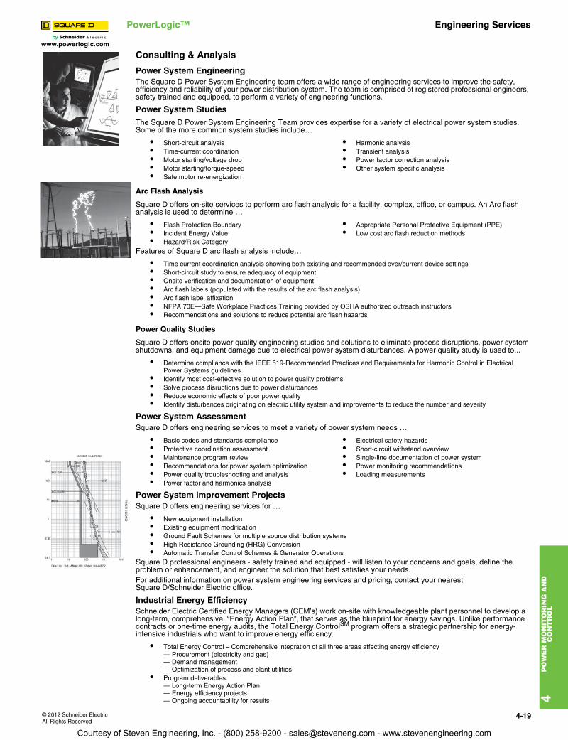
www.powerlogic.com
4P
OW
ER
MO
NIT
OR
ING
AN
D
CO
NT
RO
L
© 2012 Schneider ElectricAll Rights Reserved
4-19
PowerLogic™ Engineering Services
Consulting & Analysis
Power System EngineeringThe Square D Power System Engineering team offers a wide range of engineering services to improve the safety, efficiency and reliability of your power distribution system. The team is comprised of registered professional engineers, safety trained and equipped, to perform a variety of engineering functions.
Power System Studies The Square D Power System Engineering Team provides expertise for a variety of electrical power system studies. Some of the more common system studies include…
Arc Flash Analysis
Square D offers on-site services to perform arc flash analysis for a facility, complex, office, or campus. An Arc flash analysis is used to determine …
Features of Square D arc flash analysis include…
Power Quality Studies
Square D offers onsite power quality engineering studies and solutions to eliminate process disruptions, power system shutdowns, and equipment damage due to electrical power system disturbances. A power quality study is used to...
Power System AssessmentSquare D offers engineering services to meet a variety of power system needs …
Power System Improvement ProjectsSquare D offers engineering services for …
Square D professional engineers - safety trained and equipped - will listen to your concerns and goals, define the problem or enhancement, and engineer the solution that best satisfies your needs.For additional information on power system engineering services and pricing, contact your nearestSquare D/Schneider Electric office.
Industrial Energy EfficiencySchneider Electric Certified Energy Managers (CEM’s) work on-site with knowledgeable plant personnel to develop a long-term, comprehensive, “Energy Action Plan”, that serves as the blueprint for energy savings. Unlike performance contracts or one-time energy audits, the Total Energy ControlSM program offers a strategic partnership for energy-intensive industrials who want to improve energy efficiency.
• Short-circuit analysis• Time-current coordination• Motor starting/voltage drop• Motor starting/torque-speed• Safe motor re-energization
• Harmonic analysis• Transient analysis• Power factor correction analysis• Other system specific analysis
• Flash Protection Boundary• Incident Energy Value• Hazard/Risk Category
• Appropriate Personal Protective Equipment (PPE)• Low cost arc flash reduction methods
• Time current coordination analysis showing both existing and recommended over/current device settings• Short-circuit study to ensure adequacy of equipment• Onsite verification and documentation of equipment• Arc flash labels (populated with the results of the arc flash analysis)• Arc flash label affixation• NFPA 70E—Safe Workplace Practices Training provided by OSHA authorized outreach instructors• Recommendations and solutions to reduce potential arc flash hazards
• Determine compliance with the IEEE 519-Recommended Practices and Requirements for Harmonic Control in Electrical Power Systems guidelines
• Identify most cost-effective solution to power quality problems• Solve process disruptions due to power disturbances• Reduce economic effects of poor power quality• Identify disturbances originating on electric utility system and improvements to reduce the number and severity
• Basic codes and standards compliance• Protective coordination assessment • Maintenance program review• Recommendations for power system optimization• Power quality troubleshooting and analysis• Power factor and harmonics analysis
• Electrical safety hazards • Short-circuit withstand overview • Single-line documentation of power system • Power monitoring recommendations • Loading measurements
• New equipment installation• Existing equipment modification• Ground Fault Schemes for multiple source distribution systems• High Resistance Grounding (HRG) Conversion• Automatic Transfer Control Schemes & Generator Operations
• Total Energy Control – Comprehensive integration of all three areas affecting energy efficiency— Procurement (electricity and gas)— Demand management— Optimization of process and plant utilities
• Program deliverables:— Long-term Energy Action Plan— Energy efficiency projects— Ongoing accountability for results
Courtesy of Steven Engineering, Inc. - (800) 258-9200 - [email protected] - www.stevenengineering.com
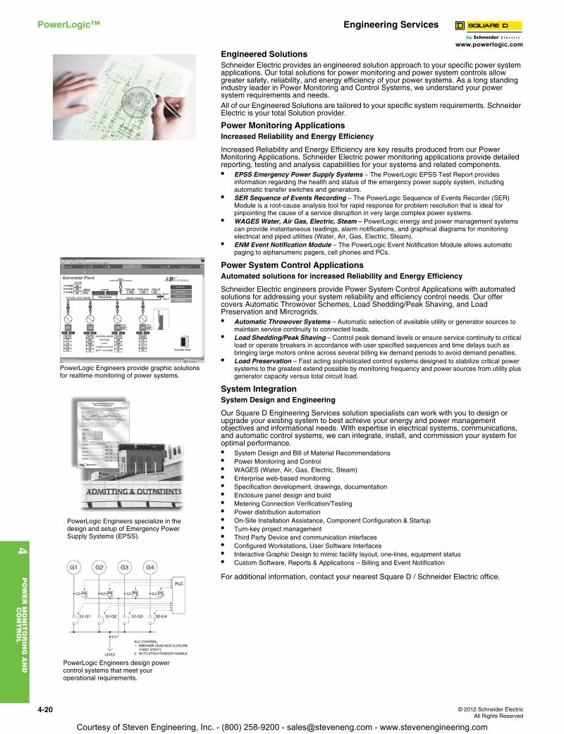
4-20 © 2012 Schneider ElectricAll Rights Reserved
www.powerlogic.com
4P
OW
ER
MO
NIT
OR
ING
AN
D
CO
NT
RO
L
PowerLogic™ Engineering Services
Engineered SolutionsSchneider Electric provides an engineered solution approach to your specific power system applications. Our total solutions for power monitoring and power system controls allow greater safety, reliability, and energy efficiency of your power systems. As a long standing industry leader in Power Monitoring and Control Systems, we understand your power system requirements and needs.All of our Engineered Solutions are tailored to your specific system requirements. Schneider Electric is your total Solution provider.
Power Monitoring ApplicationsIncreased Reliability and Energy Efficiency
Increased Reliability and Energy Efficiency are key results produced from our Power Monitoring Applications. Schneider Electric power monitoring applications provide detailed reporting, testing and analysis capabilities for your systems and related components.• EPSS Emergency Power Supply Systems – The PowerLogic EPSS Test Report provides
information regarding the health and status of the emergency power supply system, including automatic transfer switches and generators.
• SER Sequence of Events Recording – The PowerLogic Sequence of Events Recorder (SER) Module is a root-cause analysis tool for rapid response for problem resolution that is ideal for pinpointing the cause of a service disruption in very large complex power systems.
• WAGES Water, Air Gas, Electric, Steam – PowerLogic energy and power management systems can provide instantaneous readings, alarm notifications, and graphical diagrams for monitoring electrical and piped utilities (Water, Air, Gas, Electric, Steam).
• ENM Event Notification Module – The PowerLogic Event Notification Module allows automatic paging to alphanumeric pagers, cell phones and PCs.
Power System Control ApplicationsAutomated solutions for increased Reliability and Energy Efficiency
Schneider Electric engineers provide Power System Control Applications with automated solutions for addressing your system reliability and efficiency control needs. Our offer covers Automatic Throwover Schemes, Load Shedding/Peak Shaving, and Load Preservation and Mircrogrids.• Automatic Throwover Systems – Automatic selection of available utility or generator sources to
maintain service continuity to connected loads.• Load Shedding/Peak Shaving – Control peak demand levels or ensure service continuity to critical
load or operate breakers in accordance with user specified sequences and time delays such as bringing large motors online across several billing kw demand periods to avoid demand penalties.
• Load Preservation – Fast acting sophisticated control systems designed to stabilize critical power systems to the greatest extend possible by monitoring frequency and power sources from utility plus generator capacity versus total circuit load.
System IntegrationSystem Design and Engineering
Our Square D Engineering Services solution specialists can work with you to design or upgrade your existing system to best achieve your energy and power management objectives and informational needs. With expertise in electrical systems, communications, and automatic control systems, we can integrate, install, and commission your system for optimal performance.• System Design and Bill of Material Recommendations• Power Monitoring and Control • WAGES (Water, Air, Gas, Electric, Steam)• Enterprise web-based monitoring• Specification development, drawings, documentation• Enclosure panel design and build • Metering Connection Verification/Testing• Power distribution automation• On-Site Installation Assistance, Component Configuration & Startup• Turn-key project management• Third Party Device and communication interfaces • Configured Workstations, User Software Interfaces• Interactive Graphic Design to mimic facility layout, one-lines, equipment status• Custom Software, Reports & Applications – Billing and Event Notification
For additional information, contact your nearest Square D / Schneider Electric office.
PowerLogic Engineers provide graphic solutions for realtime monitoring of power systems.
PowerLogic Engineers specialize in the design and setup of Emergency Power Supply Systems (EPSS).
PowerLogic Engineers design power control systems that meet your operational requirements.
Courtesy of Steven Engineering, Inc. - (800) 258-9200 - [email protected] - www.stevenengineering.com
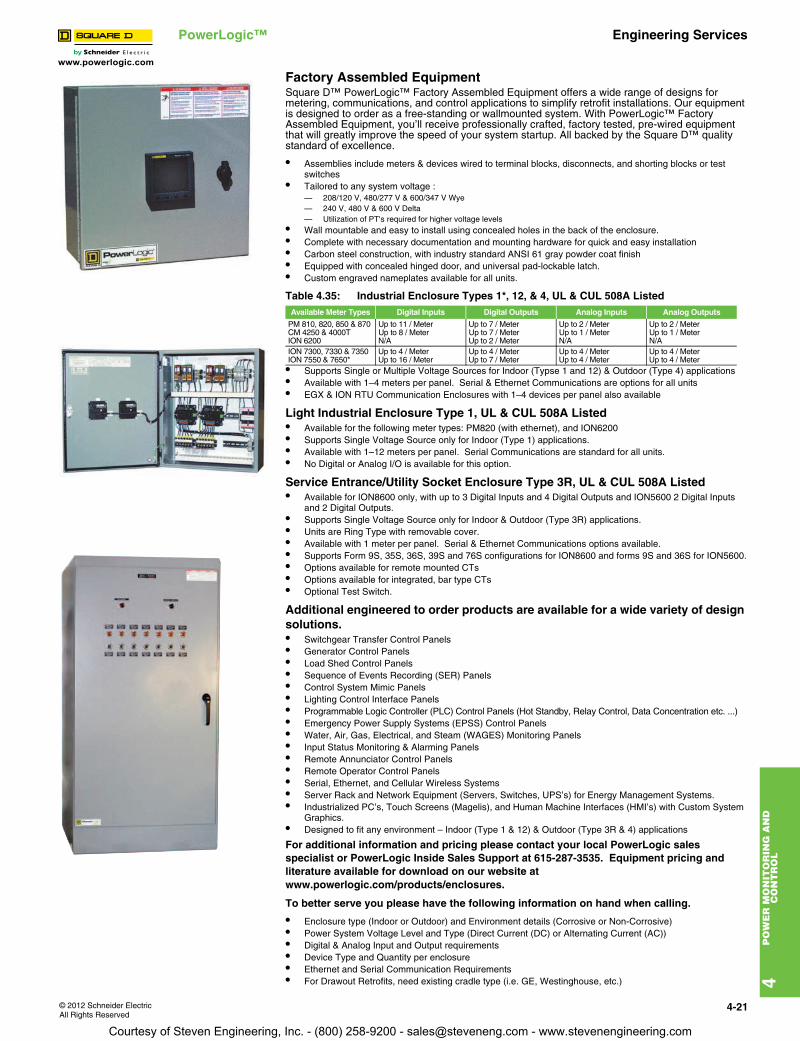
www.powerlogic.com
4P
OW
ER
MO
NIT
OR
ING
AN
D
CO
NT
RO
L
© 2012 Schneider ElectricAll Rights Reserved
4-21
PowerLogic™ Engineering Services
Factory Assembled EquipmentSquare D™ PowerLogic™ Factory Assembled Equipment offers a wide range of designs for metering, communications, and control applications to simplify retrofit installations. Our equipment is designed to order as a free-standing or wallmounted system. With PowerLogic™ Factory Assembled Equipment, you’ll receive professionally crafted, factory tested, pre-wired equipment that will greatly improve the speed of your system startup. All backed by the Square D™ quality standard of excellence.
• Assemblies include meters & devices wired to terminal blocks, disconnects, and shorting blocks or test switches
• Tailored to any system voltage :— 208/120 V, 480/277 V & 600/347 V Wye — 240 V, 480 V & 600 V Delta — Utilization of PT's required for higher voltage levels
• Wall mountable and easy to install using concealed holes in the back of the enclosure.• Complete with necessary documentation and mounting hardware for quick and easy installation • Carbon steel construction, with industry standard ANSI 61 gray powder coat finish• Equipped with concealed hinged door, and universal pad-lockable latch.• Custom engraved nameplates available for all units.
• Supports Single or Multiple Voltage Sources for Indoor (Typse 1 and 12) & Outdoor (Type 4) applications• Available with 1–4 meters per panel. Serial & Ethernet Communications are options for all units• EGX & ION RTU Communication Enclosures with 1–4 devices per panel also available
Light Industrial Enclosure Type 1, UL & CUL 508A Listed • Available for the following meter types: PM820 (with ethernet), and ION6200• Supports Single Voltage Source only for Indoor (Type 1) applications. • Available with 1–12 meters per panel. Serial Communications are standard for all units.• No Digital or Analog I/O is available for this option.
Service Entrance/Utility Socket Enclosure Type 3R, UL & CUL 508A Listed • Available for ION8600 only, with up to 3 Digital Inputs and 4 Digital Outputs and ION5600 2 Digital Inputs
and 2 Digital Outputs.• Supports Single Voltage Source only for Indoor & Outdoor (Type 3R) applications. • Units are Ring Type with removable cover.• Available with 1 meter per panel. Serial & Ethernet Communications options available.• Supports Form 9S, 35S, 36S, 39S and 76S configurations for ION8600 and forms 9S and 36S for ION5600.• Options available for remote mounted CTs• Options available for integrated, bar type CTs• Optional Test Switch.
Additional engineered to order products are available for a wide variety of design solutions.• Switchgear Transfer Control Panels• Generator Control Panels• Load Shed Control Panels• Sequence of Events Recording (SER) Panels• Control System Mimic Panels• Lighting Control Interface Panels• Programmable Logic Controller (PLC) Control Panels (Hot Standby, Relay Control, Data Concentration etc. ...)• Emergency Power Supply Systems (EPSS) Control Panels• Water, Air, Gas, Electrical, and Steam (WAGES) Monitoring Panels• Input Status Monitoring & Alarming Panels• Remote Annunciator Control Panels• Remote Operator Control Panels• Serial, Ethernet, and Cellular Wireless Systems• Server Rack and Network Equipment (Servers, Switches, UPS’s) for Energy Management Systems.• Industrialized PC’s, Touch Screens (Magelis), and Human Machine Interfaces (HMI’s) with Custom System
Graphics.• Designed to fit any environment – Indoor (Type 1 & 12) & Outdoor (Type 3R & 4) applications
For additional information and pricing please contact your local PowerLogic sales specialist or PowerLogic Inside Sales Support at 615-287-3535. Equipment pricing and literature available for download on our website at www.powerlogic.com/products/enclosures.
To better serve you please have the following information on hand when calling.
• Enclosure type (Indoor or Outdoor) and Environment details (Corrosive or Non-Corrosive)• Power System Voltage Level and Type (Direct Current (DC) or Alternating Current (AC))• Digital & Analog Input and Output requirements• Device Type and Quantity per enclosure• Ethernet and Serial Communication Requirements• For Drawout Retrofits, need existing cradle type (i.e. GE, Westinghouse, etc.)
Table 4.35: Industrial Enclosure Types 1*, 12, & 4, UL & CUL 508A ListedAvailable Meter Types Digital Inputs Digital Outputs Analog Inputs Analog Outputs
PM 810, 820, 850 & 870 Up to 11 / Meter Up to 7 / Meter Up to 2 / Meter Up to 2 / MeterCM 4250 & 4000T Up to 8 / Meter Up to 7 / Meter Up to 1 / Meter Up to 1 / MeterION 6200 N/A Up to 2 / Meter N/A N/AION 7300, 7330 & 7350 Up to 4 / Meter Up to 4 / Meter Up to 4 / Meter Up to 4 / MeterION 7550 & 7650* Up to 16 / Meter Up to 7 / Meter Up to 4 / Meter Up to 4 / Meter
Courtesy of Steven Engineering, Inc. - (800) 258-9200 - [email protected] - www.stevenengineering.com

www.powerlogic.com
4P
OW
ER
MO
NIT
OR
ING
AN
D
CO
NT
RO
L
4-22 © 2012 Schneider ElectricAll Rights Reserved
PowerLogic™ Engineering Services
Technical Engineering Support ServicesNo power management system is complete without it. Technical support should go beyond basic troubleshooting. Continued optimization and maintenance extends the life of your system and ensures it’s working efficiently and effectively. Our number one priority is to help you protect your investment and get the most out of it.• Proactive diagnostics and maintenance• Access to our self-help web portal and knowledge base • Email, telephone, and remote VPN troubleshooting assistance• On-demand and in-person training
A variety of service levels available based on your needs and budget, plus options add-ons such as onsite maintenance or 24x7 support, allows you to build the support that’s right for your system.Premium +
Our most comprehensive service level is ideal for large organizations with mission critical systems, multiple locations and/or in-house energy management expertise.Premium
Great for the experienced manager with complex power management systems and/or multiple locations, you can choose Premium support and partner with a dedicated engineer to help you drive improved system performance.Priority
Sign up for Priority support and benefit from the expertise of our senior technical engineers. They can remotely connect to your system and resolve issues while you observe or work on other tasks.Standard
We stand behind our products. If you have the time and knowledge to do-it-yourself, then we’re happy to assist you with troubleshooting or answer your questions at no extra cost.Priority Support: Excellent Service, Free Software Upgrades, Training Discounts & More!
Energy Performance ServicesUnleash Your System’s True Potential with the Power of PartnershipEnergy Performance Services helps you improve and sustain energy performance, reduce costs, and support compliance efforts. From facility insight to optimization solutions, let us customize an energy management program that’s right for you. Contact your representative and ask them about power quality analysis oran energy health check.
Solutions to fit your needs:• Facility Insight Solutions—These core energy health checks designed to evaluate your existing systems• Optimization Solutions—Let our team of experts monitor or fine-tune your systems to maximize energy
savings, efficiency and power quality.
Choose from remote or onsite solutions to ensure sustained results year over year. Vvrious funding options available. Visit www.schneider-electric.com/eps or contact us at 615-287-3535.
Power Management UniversityOur training centers offer a variety of training courses designed to improve your total energy management skills. Our instructor led courses are 70% hands-on, with each student having their own lab workstation. We have two main training centers located in Nashville, TN and Victoria, BC and offer training at a variety of Square D sites across the US and Canada.
Table 4.36: Course Description New Course No. US $ Tuition
Webinars and Online
Webinar Training (for any webinar) 3000PLUCWEBCP01 1240.00OnDemand Training (12 month access) 3000PMUDEMAND12PowerLogic SMS Systems (Factory and Regional Courses)
Regional SMS Overview — etrainer subscription 3000PMUSMSTRAINER 800.00PowerLogic ION Systems (Factory and Regional Courses)
PowerLogic PM Fundamentals Bundle (includes 3000PMUDEMAND12) 3000PMUFUNDSPMCK 2950.00PowerLogic PM Programmer 3000PMUPROG 2350.00PowerLogic PM Administrator 3000PMUADMINSPM 2350.00Regional ION Overview 3 Day 3000PMUSPM 1800.00Regional PM Overview Bundle (includes 3000PMUDEMAND12) 3000PMU35PMER 2400.00Regional ION Utility Meter Programmer 3000PMUMTRPRG 1200.00Custom Onsite Training
Customer Onsite Training 3000PMUSITE by Quote
PL1T Discount Schedule
Courtesy of Steven Engineering, Inc. - (800) 258-9200 - [email protected] - www.stevenengineering.com
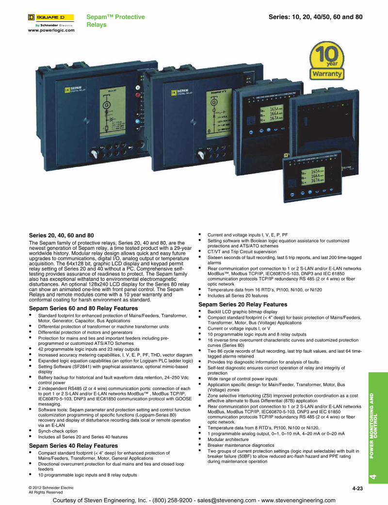
www.powerlogic.com
4P
OW
ER
MO
NIT
OR
ING
AN
D
CO
NT
RO
L
© 2012 Schneider ElectricAll Rights Reserved
4-23
Sepam™ Protective Relays
Series: 10, 20, 40/50, 60 and 80
Series 20, 40, 60 and 80The Sepam family of protective relays, Series 20, 40 and 80, are the newest generation of Sepam relay, a time tested product with a 29-year worldwide history. Modular relay design allows quick and easy future upgrades to communications, digital I/O, analog output or temperature acquisition. The 64x128 bit, graphic LCD display and keypad permit relay setting of Series 20 and 40 without a PC. Comprehensive self-testing provides assurance of readiness to protect. The Sepam family also has exceptional withstand to environmental electromagnetic disturbances. An optional 128x240 LCD display for the Series 80 relay can show an animated one-line with front panel control. The Sepam Relays and remote modules come with a 10 year warranty and conformal coating for harsh environment as standard.
Sepam Series 60 and 80 Relay Features• Standard footprint for enhanced protection of Mains/Feeders, Transformer,
Motor, Generator, Capacitor, Bus Applications• Differential protection of transformer or machine transformer units• Differential protection of motors and generators• Protection for mains and ties and important feeders including pre-
programmed or customized ATS/ATO Schemes• 42 programmable logic inputs and 23 relay outputs• Increased accuracy metering capabilities, I, V, E, P, PF, THD, vector diagram• Expanded logic equation capabilities (an option for Logipam PLC ladder logic)• Setting Software (SF2841) with graphical assistance, optional mimic-based
display• Battery backup for historical and fault waveform data retention, 24–250 Vdc
control power• 2 independent RS485 (2 or 4 wire) communication ports: connection of each
to port 1 or 2 S-LAN and/or E-LAN networks ModBus™ , ModBus TCP/IP, IEC60870-5-103, DNP3 and IEC61850 communication protocol with GOOSE messaging.
• Software tools: Sepam parameter and protection setting and control function customization programming of specific functions (Logipam-Series 80) recovery and display of disturbance recording data local or remote operation via an E-LAN
• Synch-check option• Includes all Series 20 and Series 40 features
Sepam Series 40 Relay Features• Compact standard footprint (< 4” deep) for enhanced protection of
Mains/Feeders, Transformer, Motor, General Applications• Directional overcurrent protection for dual mains and ties and closed loop
feeders• 10 programmable logic inputs and 8 relay outputs
• Current and voltage inputs I, V, E, P, PF• Setting software with Boolean logic equation assistance for customized
protections and ATS/ATO schemes• CT/VT and Trip Circuit supervision• Sixteen seconds of fault recording, last 5 trip reports, and last 200 time-tagged
alarms• Rear communication port connection to 1 or 2 S-LAN and/or E-LAN networks
ModBus™, Modbus TCP/IP, IEC60870-5-103, DNP3 and IEC 61850 communication protocols TCP/IP redundancy RS 485 (2 or 4 wire) or fiber optic network
• Temperature data from 16 RTD’s, Pt100, Ni100, or Ni120• Includes all Series 20 features
Sepam Series 20 Relay Features• Backlit LCD graphic bitmap display• Compact standard footprint (< 4” deep) for basic protection of Mains/Feeders,
Transformer, Motor, Bus (Voltage) Applications• Current or voltage inputs I, or V• 10 programmable logic inputs and 8 relay outputs• 16 inverse time overcurrent characteristic curves and customized protection
curves (Series 80)• Two 86 cycle records of fault recording, last trip fault values, and last 64 time-
tagged alarms retained• Provides trip diagnostic information for analysis of faults• Self-test diagnostic ensures correct operation of relay and integrity of
protection• Wide range of control power inputs• Application specific design for Main/Feeder, Transformer, Motor, Bus
(Voltage) zones• Zone selective interlocking (ZSI) improved protection coordination as a cost
effective alternate to Buss Differential (87B) application• Rear communication port connection to 1 or 2 S-LAN and/or E-LAN networks
ModBus, ModBus TCP/IP, IEC60870-5-103, DNP3 and IEC 61850 communication protocols TCP/IP redundancy RS 485 (2 or 4 wire) or fiber optic network.
• Temperature data from 8 RTD’s, Pt100, Ni100 or Ni120.• 1 programmable analog output, 0–1, 0–10 mA, 4–20 mA or 0–20 mA• Modular architecture• Breaker maintenance diagnostics• Two groups of current protection settings (logic input selectable) with built in
breaker failure (50BF) to allow reduced arc-flash hazard and PPE rating during maintenance operation
Courtesy of Steven Engineering, Inc. - (800) 258-9200 - [email protected] - www.stevenengineering.com
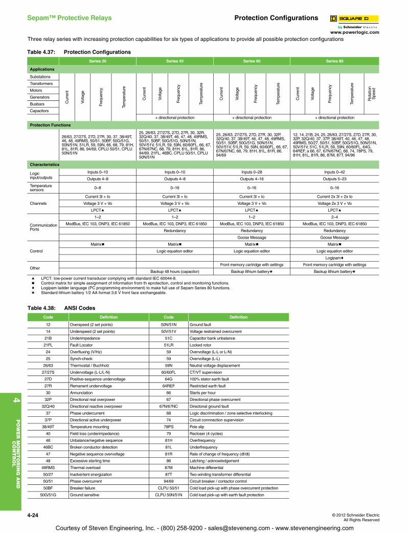
www.powerlogic.com
4P
OW
ER
MO
NIT
OR
ING
AN
D
CO
NT
RO
L
4-24 © 2012 Schneider ElectricAll Rights Reserved
Sepam™ Protective Relays Protection Configurations
Three relay series with increasing protection capabilities for six types of applications to provide all possible protection configurations
a LPCT: low-power current transducer complying with standard IEC 60044-8.b Control matrix for simple assignment of information from th eprotection, control and monitoring functions.c Logipam ladder language (PC programming environment) to make full use of Sepam Series 80 functions.d Standard lithium battery 1/2 AA format 3,6 V front face exchangeable.
Table 4.37: Protection Configurations
Series 20 Series 40 Series 60 Series 80
Applications
Substations
Cur
rent
Volta
ge
Freq
uenc
y
Tem
pera
ture
Cur
rent
Volta
ge
Freq
uenc
y
Tem
pera
ture
Cur
rent
Volta
ge
Freq
uenc
y
Tem
pera
ture
Cur
rent
Volta
ge
Freq
uenc
y
Tem
pera
ture
Rot
atio
nS
peed
Transformers
Motors
Generators
Busbars
Capacitors
+ directional protection + directional protection + directional protection
Protection Functions
26/63, 27/27S, 27D, 27R, 30, 37, 38/49T, 46, 48, 49RMS, 50/51, 50BF, 50G/51G, 50N/51N, 51LR, 59, 59N, 66, 68, 79, 81H, 81L, 81R, 86, 94/69, CPLU 50/51, CPLU 50N/51N
25, 26/63, 27/27S, 27D, 27R, 30, 32R, 32Q/40, 37, 38/49T, 46, 47, 48, 49RMS, 50/51, 50BF, 50G/51G, 50N/51N, 50V/51V, 51LR, 59, 59N, 60/60FL, 66, 67, 67N/67NC, 68, 79, 81H, 81L, 81R, 86, 94/69, 21FL, 46BC, CPLU 50/51, CPLU 50N/51N
25, 26/63, 27/27S, 27D, 27R, 30, 32P, 32Q/40, 37, 38/49T, 46, 47, 48, 49RMS, 50/51, 50BF, 50G/51G, 50N/51N, 50V/51V, 51LR, 59, 59N, 60/60FL, 66, 67, 67N/67NC, 68, 79, 81H, 81L, 81R, 86, 94/69
12, 14, 21B, 24, 25, 26/63, 27/27S, 27D, 27R, 30, 32P, 32Q/40, 37, 37P, 38/49T, 40, 46, 47, 48, 49RMS, 50/27, 50/51, 50BF, 50G/51G, 50N/51N, 50V/51V, 51C, 51LR, 59, 59N, 60/60FL, 64G, 64REF, a 66, 67, 67N/67NC, 68, 74, 78PS, 79, 81H, 81L, 81R, 86, 87M, 87T, 94/96
Characteristics
Logic input/outputs
Inputs 0–10 Inputs 0–10 Inputs 0–28 Inputs 0–42
Outputs 4–8 Outputs 4–8 Outputs 4–16 Outputs 5–23
Temperature sensors 0–8 0–16 0–16 0–16
Channels
Current 3I + Io Current 3I + Io Current 3I + Io Current 2x 3I + 2x Io
Voltage 3 V + Vo Voltage 3 V + Vo Voltage 3 V + Vo Voltage 2x 3 V + Vo
LPCTa LPCTa LPCTa LPCTa
Communication Ports
1–2 1–2 1–2 2–4
ModBus, IEC 103, DNP3, IEC 61850 ModBus, IEC 103, DNP3, IEC 61850 ModBus, IEC 103, DNP3, IEC 61850 ModBus, IEC 103, DNP3, IEC 61850
Redundancy Redundancy Redundancy
Goose Message Goose Message
Control
Matrixb Matrixb Matrixb Matrixb
Logic equation editor Logic equation editor Logic equation editor
Logipamc
OtherFront memory cartridge with settings Front memory cartridge with settings
Backup 48 hours (capacitor) Backup lithium batteryd Backup lithium batteryd
Table 4.38: ANSI Codes
Code Definition Code Definition
12 Overspeed (2 set points) 50N/51N Ground fault
14 Underspeed (2 set points) 50V/51V Voltage restrained overcurrent
21B Underimpedance 51C Capacitor bank unbalance
21FL Fault Locator 51LR Locked rotor
24 Overfluxing (V/Hz) 59 Overvoltage (L-L or L-N)
25 Synch-check 59 Overvoltage (L-L)
26/63 Thermostat / Buchholz 59N Neutral voltage displacement
27/27S Undervoltage (L-L/L-N) 60/60FL CT/VT supervision
27D Positive-sequence undervoltage 64G 100% stator earth fault
27R Remanent undervoltage 64REF Restricted earth fault
30 Annunciation 66 Starts per hour
32P Directional real overpower 67 Directional phase overcurrent
32Q/40 Directional reactive overpower 67N/67NC Directonal ground fault
37 Phase undercurrent 68 Logic discrimination / zone selective interlocking
37P Directional active underpower 74 Circuit connnection supervision
38/49T Temperature mounting 78PS Pole slip
40 Field loss (underimpedance) 79 Recloser (4 cycles)
46 Unbalance/negative sequence 81H Overfrequency
46BC Broken conductor detection 81L Underfrequency
47 Negative sequence overvoltage 81R Rate of change of frequency (df/dt)
48 Excessive starting time 86 Latching / acknowledgement
49RMS Thermal overload 87M Machine differential
50/27 Inadvertent energization 87T Two-winding transformer differential
50/51 Phase overcurrent 94/69 Circuit breaker / contactor control
50BF Breaker failure CLPU 50/51 Cold load pick-up with phase overcurrent protection
50G/51G Ground sensitive CLPU 50N/51N Cold load pick-up with earth fault protection
Courtesy of Steven Engineering, Inc. - (800) 258-9200 - [email protected] - www.stevenengineering.com
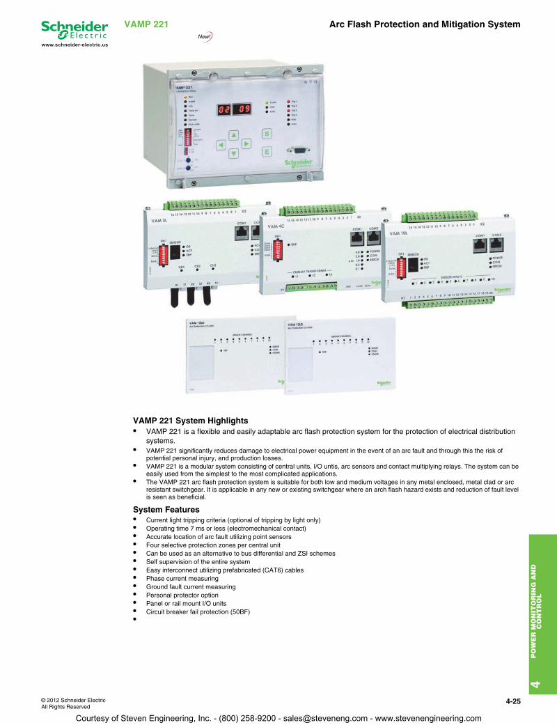
© 2012 Schneider ElectricAll Rights Reserved
4-25
www.schneider-electric.us
4P
OW
ER
MO
NIT
OR
ING
AN
D
CO
NT
RO
L
VAMP 221 Arc Flash Protection and Mitigation System
VAMP 221 System Highlights• VAMP 221 is a flexible and easily adaptable arc flash protection system for the protection of electrical distribution
systems.• VAMP 221 significantly reduces damage to electrical power equipment in the event of an arc fault and through this the risk of
potential personal injury, and production losses.• VAMP 221 is a modular system consisting of central units, I/O untis, arc sensors and contact multiplying relays. The system can be
easily used from the simplest to the most complicated applications.• The VAMP 221 arc flash protection system is suitable for both low and medium voltages in any metal enclosed, metal clad or arc
resistant switchgear. It is applicable in any new or existing switchgear where an arch flash hazard exists and reduction of fault level is seen as beneficial.
System Features• Current light tripping criteria (optional of tripping by light only)• Operating time 7 ms or less (electromechanical contact)• Accurate location of arc fault utilizing point sensors• Four selective protection zones per central unit• Can be used as an alternative to bus differential and ZSI schemes• Self supervision of the entire system• Easy interconnect utilizing prefabricated (CAT6) cables• Phase current measuring• Ground fault current measuring• Personal protector option• Panel or rail mount I/O units• Circuit breaker fail protection (50BF)•
Courtesy of Steven Engineering, Inc. - (800) 258-9200 - [email protected] - www.stevenengineering.com
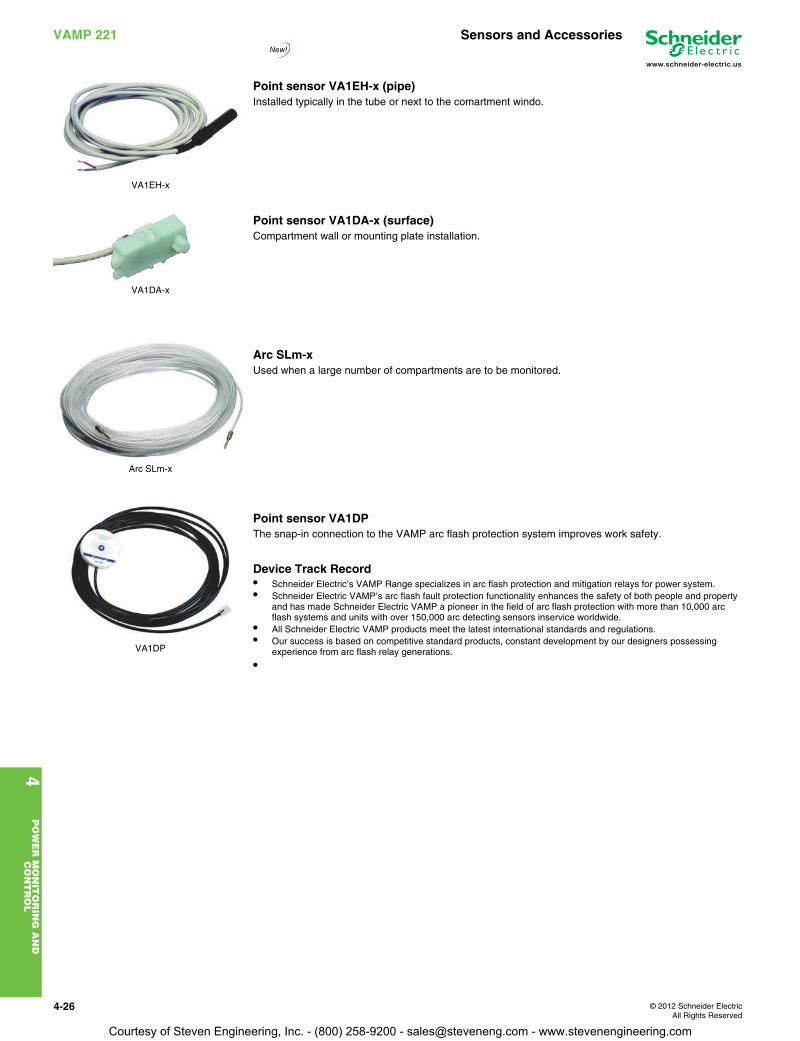
4-26 © 2012 Schneider ElectricAll Rights Reserved
4P
OW
ER
MO
NIT
OR
ING
AN
D
CO
NT
RO
L
www.schneider-electric.us
VAMP 221 Sensors and Accessories
Point sensor VA1EH-x (pipe)Installed typically in the tube or next to the comartment windo.
Point sensor VA1DA-x (surface)Compartment wall or mounting plate installation.
Arc SLm-xUsed when a large number of compartments are to be monitored.
Point sensor VA1DPThe snap-in connection to the VAMP arc flash protection system improves work safety.
Device Track Record• Schneider Electric’s VAMP Range specializes in arc flash protection and mitigation relays for power system.• Schneider Electric VAMP’s arc flash fault protection functionality enhances the safety of both people and property
and has made Schneider Electric VAMP a pioneer in the field of arc flash protection with more than 10,000 arc flash systems and units with over 150,000 arc detecting sensors inservice worldwide.
• All Schneider Electric VAMP products meet the latest international standards and regulations.• Our success is based on competitive standard products, constant development by our designers possessing
experience from arc flash relay generations.
•
VA1EH-x
VA1DA-x
Arc SLm-x
VA1DP
Courtesy of Steven Engineering, Inc. - (800) 258-9200 - [email protected] - www.stevenengineering.com
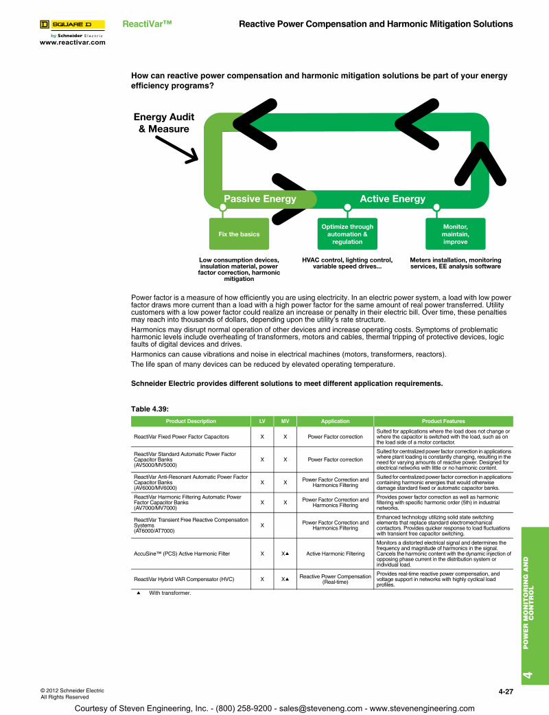
www.reactivar.com
4P
OW
ER
MO
NIT
OR
ING
AN
D
CO
NT
RO
L
© 2012 Schneider ElectricAll Rights Reserved
4-27
ReactiVar™ Reactive Power Compensation and Harmonic Mitigation Solutions
How can reactive power compensation and harmonic mitigation solutions be part of your energy efficiency programs?
Power factor is a measure of how efficiently you are using electricity. In an electric power system, a load with low power factor draws more current than a load with a high power factor for the same amount of real power transferred. Utility customers with a low power factor could realize an increase or penalty in their electric bill. Over time, these penalties may reach into thousands of dollars, depending upon the utility’s rate structure.Harmonics may disrupt normal operation of other devices and increase operating costs. Symptoms of problematic harmonic levels include overheating of transformers, motors and cables, thermal tripping of protective devices, logic faults of digital devices and drives.Harmonics can cause vibrations and noise in electrical machines (motors, transformers, reactors).The life span of many devices can be reduced by elevated operating temperature.
Schneider Electric provides different solutions to meet different application requirements.
a With transformer.
Table 4.39:
Product Description LV MV Application Product Features
ReactiVar Fixed Power Factor Capacitors X X Power Factor correctionSuited for applications where the load does not change or where the capacitor is switched with the load, such as on the load side of a motor contactor.
ReactiVar Standard Automatic Power Factor Capacitor Banks(AV5000/MV5000)
X X Power Factor correction
Suited for centralized power factor correction in applications where plant loading is constantly changing, resulting in the need for varying amounts of reactive power. Designed for electrical networks with little or no harmonic content.
ReactiVar Anti-Resonant Automatic Power Factor Capacitor Banks(AV6000/MV6000)
X X Power Factor Correction and Harmonics Filtering
Suited for centralized power factor correction in applications containing harmonic energies that would otherwise damage standard fixed or automatic capacitor banks.
ReactiVar Harmonic Filtering Automatic Power Factor Capacitor Banks(AV7000/MV7000)
X X Power Factor Correction and Harmonics Filtering
Provides power factor correction as well as harmonic filtering with specific harmonic order (5th) in industrial networks.
ReactiVar Transient Free Reactive Compensation Systems(AT6000/AT7000)
X Power Factor Correction and Harmonics Filtering
Enhanced technology utilizing solid state switching elements that replace standard electromechanical contactors. Provides quicker response to load fluctuations with transient free capacitor switching.
AccuSine™ (PCS) Active Harmonic Filter X Xa Active Harmonic Filtering
Monitors a distorted electrical signal and determines the frequency and magnitude of harmonics in the signal. Cancels the harmonic content with the dynamic injection of opposing phase current in the distribution system or individual load.
ReactiVar Hybrid VAR Compensator (HVC) X Xa Reactive Power Compensation(Real-time)
Provides real-time reactive power compensation, and voltage support in networks with highly cyclical load profiles.
Courtesy of Steven Engineering, Inc. - (800) 258-9200 - [email protected] - www.stevenengineering.com

4-28 © 2012 Schneider ElectricAll Rights Reserved
www.reactivar.com
4P
OW
ER
MO
NIT
OR
ING
AN
D
CO
NT
RO
L
ReactiVar™ Low Voltage Fixed Capacitors
Low Voltage Fixed CapacitorsReacatiVar low voltage fixed capacitors are ideally suited for power factor correction applications where the load does not change or where the capacitor is switched with the load, such as on the load side of a motor starter. ReactiVar fixed capacitors are best suited for applications where there are no harmonic currents or voltages present.
Features:• Heavy edge, slope metallizations and wave-cut profile to ensure high inrush current capabilities.• Special resistivity and profile metallization for better self-healing and enhanced life (up to 130,000 hours).• Unique safety feature which disconnects the capacitors at the end of their useful life electrically.• Less than 0.5w/kVAR losses, including discharage resistors.• Constructed with a dry type metalized polypropylene capacitor element with no liquid dielectrics.• Can be easily mounted inside panels or in a stand alone configuration.
a Conductor should be copper and rated 90 °C min. Refer to local electrical codes for proper wire sizeb Consult local electrical codes for proper sizing of molded case circuit breaker frame or disconnect switch rating
Note: For fused unit, add suffix “F” to the existing part number. Consult Schneider Electric sales office for pricing.
Table 4.40: Unfused 208 V 3 phase/ 60Hz unit
kVAR rating Regular duty Indoor NEMA 1 unit Rated Current (A) Recommended copper wire sizea
Recommended circuit protection device ratingb
@ 208 V Catalog Number $ Price @ 208 V AWG Fuse Circuit breaker
2 PFCD1002 959.00 6.3 14 15 155 PFCD1005 1187.00 13.6 10 30 206 PFCD1006 1364.00 17.7 10 40 25
7.5 PFCD1007 1538.00 20.9 8 45 3010 PFCD1010 1924.00 27.1 8 60 4013 PFCD1013 2376.00 35.4 6 75 50 15 PFCD1015 2633.00 41.7 4 90 6017 PFCD1017 2957.00 48 4 100 7021 PFCD1021 3101.00 59.4 3 125 9025 PFCD1025 5330.00 68.8 2 150 10027 PFCD1027 5430.00 75.1 2 150 110 30 PFCD1030 6243.00 83.4 1 175 12534 PFCD1033 7608.00 93.8 1/0 200 150
37.5 PFCD1037 9251.00 104.3 2/0 225 15041 PFCD1040 9618.00 114.7 2/0 250 175 45 PFCD1045 9984.00 125.1 3/0 250 17549 PFCD1048 10245.00 135.5 4/0 300 20053 PFCD1053 10505.00 147 4/0 300 225 60 PFCD1060 11026.00 168.9 300 kcmil 350 250 70 PFCD1070 11786.00 198.1 350 kcmil 450 300 80 PFCD1080 12437.00 222 500 kcmil 450 350
Table 4.41: Unfused 240 V 3 phase/ 60Hz unit
kVAR rating Regular duty Indoor NEMA 1 unit Rated Current (A) Recommended copper wire sizea
Recommended circuit protection device ratingb
@ 240 V Catalog Number $ Price @ 240 V AWG Fuse Circuit breaker
3 PFCD2003 959 7.2 14 15 156 PFCD2006 1187.00 15.6 10 35 258 PFCD2008 1364.00 20.5 8 45 30
10 PFCD2010 1538.00 24.1 8 50 3513 PFCD2013 1924.00 31.3 6 70 45 15 PFCD2015 2117.00 36.1 6 75 50 17.5 PFCD2017 2376.00 40.9 6 90 60 20 PFCD2020 2633.00 48.1 4 100 70 22.5 PFCD2023 2957.00 55.3 3 125 80 25 PFCD2025 3101.00 61.4 3 125 90
27.5 PFCD2028 4181.00 68.6 2 150 100 30 PFCD2030 5045.00 72.2 2 150 100 32.5 PFCD2033 5330.00 79.4 1 175 110 37.5 PFCD2036 5430.00 86.6 1 175 125 40 PFCD2040 6243.00 96.2 1/0 200 150 45 PFCD2045 7608.00 108.3 2/0 225 150 50 PFCD2050 9251.00 120.3 2/0 250 175 60 PFCD2060 9984.00 144.4 4/0 300 200 70 PFCD2070 10499.00 169.6 300 kcmil 350 250 80 PFCD2080 11026.00 194.9 350 kcmil 400 300 90 PFCD2090 11557.00 218.9 400 kcmil 450 300 100 PFCD2100 12072.00 239.4 500 kcmil 500 350
DE2C Discount Schedule
Courtesy of Steven Engineering, Inc. - (800) 258-9200 - [email protected] - www.stevenengineering.com
www.reactivar.com
4P
OW
ER
MO
NIT
OR
ING
AN
D
CO
NT
RO
L
© 2012 Schneider ElectricAll Rights Reserved
4-29
ReactiVar™ Low Voltage Fixed Capacitors
Low Voltage Fixed Capacitors
a Conductor should be copper and rated 90 °C min. Refer to local electrical codes for proper wire sizeb Consult local electrical codes for proper sizing of molded case circuit breaker frame or disconnect switch rating
Note: For fused unit, add suffix “F” to the existing part number. Consult Schneider Electric sales office for pricing.
Application Note: Capacitors are low impedance path for the harmonic currents produced by variable frequency drives, motor soft starters, welders, computers, PLCs, robotics and other electronic equipment. These harmonic currents can cause the capacitor to overheat, and shorten its life. Furthermore, the resonant circuit formed by shunt capacitors coupled with system inductances (motors and transformers) can amplify harmonic currents and voltages in the electrical network. This amplification can cause nuisance fuse operation and/or damage to electrical equipment including capacitors and other electronic devices. If power factor correction is required in the network where harmonic is present, please contact your nearest Square D/Schneider Electric sales office for assistance.
Table 4.42: Unfused 480V 3 phase/ 60Hz unit
kVAR rating Regular duty Indoor NEMA 1 unit Rated Current (A) Recommended copper wire sizea
Recommended circuit protection device ratingb
@ 480 V Catalog Number $ Price @ 480 V AWG Fuse Circuit breaker
6 PFCD4006 929.00 7.2 14 15 15 8 PFCD4008 1022.00 10.2 12 20 15
10 PFCD4010 1077.00 12 12 25 20 12.5 PFCD4012 1215.00 15 10 30 25 15 PFCD4015 1329.00 18 10 40 30 17 PFCD4017 1374.00 19.8 8 40 30 20 PFCD4020 1479.00 24 8 50 35 25 PFCD4025 1655.00 30 6 60 45
27.5 PFCD4027 1754.00 33 6 70 50 30 PFCD4030 1851.00 36 6 75 50 33 PFCD4033 1953.00 39.6 6 80 60 35 PFCD4035 2102.00 42 4 90 60 40 PFCD4040 2358.00 48 4 100 70 45 PFCD4045 2519.00 54 4 110 75 50 PFCD4050 2676.00 60 3 125 90 60 PFCD4060 3975.00 72 2 150 100 65 PFCD4065 4200.00 78 1 175 110 70 PFCD4070 4280.00 84 1 175 125 75 PFCD4075 4434.00 90 1/0 200 125 80 PFCD4080 4695.00 96 1/0 200 150 90 PFCD4090 5217.00 108 2/0 225 150 100 PFCD4100 5738.00 120 2/0 250 175 125 PFCD4125 7148.00 150 250 300 225 150 PFCD4150 8556.00 180 300 400 250 175 PFCD4175 9561.00 210 400 450 300 200 PFCD4200 10565.00 240 500 500 350
Table 4.43: Unfused 600V 3 phase/ 60Hz unit
kVAR rating Regular duty Indoor NEMA 1 unit Rated Current (A) Recommended copper wire sizea
Recommended circuit protection device ratingb
600 V Catalog Number $ Price @ 600 V AWG Fuse Circuit Breaker
10 PFCD6010 1077.00 9.6 12 20 15 15 PFCD6015 1329.00 14.4 10 30 20 20 PFCD6020 1479.00 19.2 10 40 30 23 PFCD6022 1550.00 22.1 8 50 35 25 PFCD6025 1655.00 24 8 50 35 27 PFCD6027 1754.00 26 8 50 40 30 PFCD6030 1851.00 28.8 8 60 45 35 PFCD6035 2102.00 33.6 6 70 50 40 PFCD6040 2358.00 38.4 6 80 60 45 PFCD6045 2519.00 43.2 4 90 60 50 PFCD6050 2676.00 48 4 100 70 60 PFCD6060 3975.00 57.6 3 125 80 70 PFCD6070 4280.00 67.2 3 150 100 75 PFCD6075 4434.00 72 2 150 100 80 PFCD6080 4695.00 76.8 1 150 110 90 PFCD6090 5217.00 86.4 1 175 125 100 PFCD6100 5738.00 96 1/0 200 150 125 PFCD6125 7148.00 120 3/0 250 175 150 PFCD6150 8556.00 144 4/0 300 200 175 PFCD6175 9561.00 168 300 kcmil 350 250
DE2C Discount Schedule
Courtesy of Steven Engineering, Inc. - (800) 258-9200 - [email protected] - www.stevenengineering.com
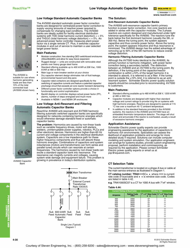
www.reactivar.com
4P
OW
ER
MO
NIT
OR
ING
AN
D
CO
NT
RO
L
4-30 © 2012 Schneider ElectricAll Rights Reserved
ReactiVar™ Low Voltage Automatic Capacitor Banks
Low Voltage Standard Automatic Capacitor Banks
The AV5000 standard automatic power factor correction banks are designed for centralized power factor correction to supply varying amounts of reactive power required to compensate for changing load conditions. The AV5000 banks are ideally suited for facility electrical distribution systems with TDD (total harmonic current distortion) < = 5% and THD(V) (total harmonic voltage distortion) < = 5%. An advanced power factor controller measures plant power factor via a single remote CT. Plus, it switches capacitor modules in and out of service to maintain a user selected target power factor.
Main Features:• Modular construction; free standing QED switchboard enclosures
(30wx36dx90h) and allow for easy future expansion• Rugged design — units are constructed with removable steel
panels over heavy gauge steel frame• Standard offering available up to 400 kVAR at 208 Vac, 1000
kVAR at 480 or 600 Vac• Main lugs or main breaker section at your choice• Dry capacitor element design eliminates risk of fluid leakage,
environmental hazard and drip pans• Capacitor rated contactors are designed specifically for the
switching of capacitive currents and feature a patented capacitor precharge circuit that exceeds air-core reactor transient dampening
• Different power factor controller options provide a choice in functionality and control sophistication
• Backlit display on controller displays actual power factor (PF), alarms, number of steps energized and much more
• Available in NEMA 1 and NEMA 3R enclosures
Low Voltage Anti-Resonant and Filtering Automatic Capacitor Banks ReactiVar AV6000 anti-resonant and AV7000 harmonic filtering automatic switched capacitor banks are specifically designed for networks containing harmonic energies which would otherwise damage standard fixed or automatic capacitor banks.The problem: Harmonics are caused by non-linear loads such as variable frequency drives, motor soft starters, welders, uninterruptable power supplies, robotics, PLCs and other electronic devices. Harmonics are higher-than-60 Hz current and voltage components in the electrical distribution system. Capacitors are a low impedance path for these higher frequency components and thus will absorb these harmonic energies. Combinations of capacitors and system inductances (motors and transformers) can form series and parallel tuned circuits which can resonate at certain frequencies. The harmonics caused by non-linear loads can excite a standard capacitor bank into resonance. The resonance can magnify currents and voltages, causing system wide damage and equipment failure. This problem is growing in prevalence in today's distribution systems.
Single Line (Typical)Diagram 1
The Solution:Anti-Resonant Automatic Capacitor BanksThe AV6000 anti-resonance capacitor bank's primary function is power factor correction. Iron core reactors are added in series with the capacitor modules. The 3 phase reactors are custom designed and manufactured under tight tolerance specifically for the AV6000. The reactors tune the bank below the first dominant harmonic (usually the 5th, or 300 Hz). Below the tuning point, the system appears capacitive and thus corrects power factor. Above the tuning point, the system appears Inductive and thus resonance is minimized. The AV6000 design has the added advantage of removing up to 50% of the 5th harmonic to reduce overall voltage distortion.Harmonic Filtering Automatic Capacitor BanksAlthough the AV7000 looks identical to the AV6000, its primary function is harmonic mitigation, with power factor correction being a secondary benefit. The distinction between an AV6000 and an AV7000 is the tuning point. By definition, if the tuning point of the capacitor/reactor combination is within ±10% of the target harmonic it is intended to absorb, it is referred to as a filter. If the tuning point is outside the ±10% limit, it is referred to as an anti-resonant system. Schneider Electric power quality solution experts should be consulted prior to recommending AV7000 to customers.
Main Features:• Standard offering available up to 480 kVAR at 208 V, 1200 kVAR
at 480 or 600 Vac• Capacitor modules are designed with higher than standard
voltage and current ratings to provide long life on systems with high harmonic energies. Reactors are designed to operate at 115 °C rise over a maximum 40 °C ambient temperature.
• In addition to the standard features provided in the AV5000 systems, the reactors in the AV6000 and AV7000 have an embedded thermistor temperature detector. The stage will shut down and annunciate if the reactor is overheated, usually a result of excessive harmonic energies
Application Assistance:Schneider Electric power quality experts can provide engineering assistance for the application of capacitors in harmonic rich environments. Specialists can assess the likelihood of application problems and arrange for more detailed study if required. Solutions can include computer modeling and system simulation. Our application engineers can arrange for systems studies, provide custom engineering proposal, perform installation and commissioning, as required by the application. Please contact Schneider Electric power quality experts or email us at [email protected].
CT Selection TableThe current transformer is located on a phase A bus or cable at the main service entrance as illustrated in Diagram 1.CT catalog number: TRAI••••SCc c where •••• is current rate code of bus/cable and c c is window size code. Codes are listed in table 4.42.e.g. TRAI1000SC07 is a CT for 1000 A bus with 7"x4" window.
The AV5000 is suitable for use where harmonic generating loads are less than 15% of the total connected load (AV5000 shown here).
AV6000 Capacitor Bank
Main Transformer
Main Breaker
External CurrentTransformerRatio XXXX/5
SubFeed
SubFeed
SubFeed
SubFeed
600 kVARAutomaticCapacitor
Bank
Table 4.44: Current Rating of Bus/Cable Window Size
Amperes Rating Code••••
7" x 4" Size Codec c
11" x 4" Size Codec c
300 0300 07 11400 0400 07 11500 0500 07 11600 0600 07 11750 0750 07 11800 0800 07 111000 1000 07 111200 1200 07 111500 1500 07 111600 1600 07 112000 2000 07 112500 2500 07 113000 3000 07 113500 3500 07 114000 4000 07 115000 5000 N/A 116000 6000 N/A 11
Courtesy of Steven Engineering, Inc. - (800) 258-9200 - [email protected] - www.stevenengineering.com
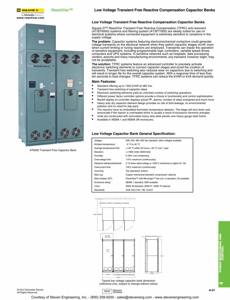
www.reactivar.com
4P
OW
ER
MO
NIT
OR
ING
AN
D
CO
NT
RO
L
© 2012 Schneider ElectricAll Rights Reserved
4-31
ReactiVar™ Low Voltage Transient Free Reactive Compensation Capacitor Banks
Low Voltage Transient Free Reactive Compensation Capacitor Banks
Square D™ ReactiVar Transient Free Reactive Compensation (TFRC) anti-resonant (AT/BT6000) systems and filtering system (AT/BT7000) are ideally suited for use on electrical systems where connected equipment is extremely sensitive to variations in the supply voltage.The problem: Capacitor systems featuring electromechanical contactors could generate voltage transients on the electrical network when they switch capacitor stages on/off, even when current limiting or tuning reactors are employed. Transients can impair the operation of sensitive equipment, including programmable logic controllers, variable speed drives, computers and UPS systems. In sensitive networks such as hospitals, data processing centers, airports and many manufacturing environments, any transient, however slight, may not be acceptable.The solution: TFRC systems feature an advanced controller to precisely activate electronic switching elements to connect capacitor stages and avoid the creation of transients. Transient free switching also reduces wear on capacitors due to switching and will result in longer life for the overall capacitor system. With a response time of less than ten seconds to load changes, TFRC systems can reduce the kVAR or kVA demand quickly.
Main Features:• Standard offering up to 1350 kVAR at 480 Vac• Transient free switching of capacitor steps• Electronic switching elements yield an unlimited number of switching operations• Different power factor controller options provide a choice in functionality and control sophistication• Backlit display on controller displays actual PF, alarms, number of steps energized and much more• Heavy duty dry capacitor element design provides no risk of fluid leakage, no environmental
pollution and no need for drip pans• The reactors have an embedded thermistor temperature detector. The stage will shut down and
annunciate if the reactor is overheated which is usually a result of excessive harmonic energies• Units are constructed with removable heavy duty steel panels over heavy gauge steel frame.• Available in NEMA 1 and NEMA 3R enclosures.
Low Voltage Capacitor Bank General Specification:
Voltage: 208, 240, 480, 600 Vac standard, other voltages available
Ambient temperature: -5 °C to 40 °C
Average temperature limit: <=40 °C within 24 hours, <35 °C over 1 year
Elevation: <=1800 meter (6000 feet)
Humidity: 0–95% non-condensing
Overvoltage limit: 110% maximum (continuously)
Dielectric withstand test level: 2.15 times rated voltage or 1000 V, whichever is higher for 10s
Overcurrent limit: 135% maximum (continuously)
Incoming: Top (standard), bottom.
Main lug: Copper mechanical standard, compression optional
Main breaker (BT): PowerPact™ with Micrologic™ trip unit. LI standard, LSI available
Enclosure rating: NEMA 1 standard, N3R available
Color: ANSI 49 standard, ANSI 61, ANSI 70 optional
Standards: CSA C22.2 No. 190, UL810
AT6000 Transient Free Capacitor Bank
30.00036.000
REMOVABLE LIFTING LUGS
6" MINIMUM, IF SURFACE IS FLAMMABLE 24" MINIMUM
91.50
70"/88" APPROX.
WIDTH
ADDITIONAL SECTIONS AS REQUIRED
PULL BOX12" OR 24"
Typical low voltage capacitor bank dimension(reference only, subject to change without notice)
DE2C Discount Schedule
Courtesy of Steven Engineering, Inc. - (800) 258-9200 - [email protected] - www.stevenengineering.com
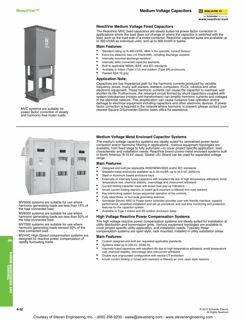
www.reactivar.com
4P
OW
ER
MO
NIT
OR
ING
AN
D
CO
NT
RO
L
4-32 © 2012 Schneider ElectricAll Rights Reserved
ReactiVar™ Medium Voltage Capacitors
ReactiVar Medium Voltage Fixed CapacitorsThe ReactiVar MVC fixed capacitors are ideally suited for power factor correction in applications where the load does not change or where the capacitor is switched with the load, such as the load side of a motor contactor. ReactiVar capacitor sizes are available up to 300 kVAR as individual units, and up to 900 kVAR in banks.
Main Features:• Standard rating up to 900 kVAR, 4800 V (for specials, consult factory)• Extra low dielectric loss (<0.15w/kVAR), including discharge resistors• Internally mounted discharge resistors• Internally delta connected capacitor elements• Built to applicable NEMA, IEEE, and IEC standards• Available in indoor (Type 1/12) and outdoor (Type 3R) enclosures• Painted ASA 70 gray
Application Note:Capacitors are low impedance path for the harmonic currents produced by variable frequency drives, motor soft starters, welders, computers, PLCs, robotics and other electronic equipment. These harmonic currents can cause the capacitor to overheat, and shorten its life. Furthermore, the resonant circuit formed by shunt capacitors coupled with system inductances (motors and transformers) can amplify harmonic currents and voltages in the electrical network. This amplification can cause nuisance fuse operation and/or damage to electrical equipment including capacitors and other electronic devices. If power factor correction is required in the network where harmonic is present, please contact your nearest Square D/Schneider Electric sales office for assistance.
Medium Voltage Metal Enclosed Capacitor SystemsThe medium voltage capacitor systems are ideally suited for centralized power factor correction and/or harmonic filtering in applications. Various equipment topologies are available, from fixed stage to fully automatic—to cover project specific application, load characteristic and installation needs. ReactiVar brand covers metal enclosed systems built in North America (5/15 kV class). Global =S= Brand can be used for expanded voltage range.
Main Features:• Designed and built per applicable ANSI/NEMA/IEEE and/or IEC standards• Standard metal enclosures available up to 20 mVAR, up to 34.5 kV, 50/60 Hz• Steel or Aluminum based enclosure bays• Externally or internally fused capacitors with excellent life due to high temperature withstand, small
temperature rise, chemical stability, overvoltage and overcurrent withstand.• Current limiting capacitor fuses with blown fuse pop-up indicators• Inrush current limiting reactors or tuned (anti-resonant or filtered) iron core reactors• Key interlocking system forces sequential operation of the controls,• Fully rated three- or four-pole grounding switches• Schneider Electric NRC12 Power factor controller provides user with friendly interface, superior
performance, simplified installation and set-up procedure, and real time monitoring and protection features for the capacitor system.
• Available in Type 1 indoor and 3R outdoor enclosure types
High Voltage Reactive Power Compensation SystemsThe high voltage reactive power compensation systems are ideally suited for installation at utility distribution and transmission grids. Various equipment topologies are available to cover project specific utility application, and installation needs. Typically these compensation systems are open style, rack mounted, installed in utility substation areas.
Main Features:• Custom designed and built per requested applicable standards• Systems rated up to 230 kV, 50/60 Hz• Internally fused capacitors with excellent life due to high temperature withstand, small temperature
rise, chemical stability, overvoltage and overcurrent withstand. • Double wye ungrounded configuration with neutral CT protection• Inrush current limiting or tuned (anti-resonant or filtered) air core, open style reactors
MVC systems are suitable for power factor correction of steady and harmonic-free motor loads.
MV5000 systems are suitable for use where harmonic generating loads are less than 15% of the total connected load.MV6000 systems are suitable for use where harmonic generating loads are less than 50% of the total connected load.MV7000 systems are suitable for use where harmonic generating loads exceed 50% of the total connected load.MVHVC High-Speed compensation systems are designed for reactive power compensation of rapidly fluctuating loads
Courtesy of Steven Engineering, Inc. - (800) 258-9200 - [email protected] - www.stevenengineering.com

www.reactivar.com
© 2012 Schneider ElectricAll Rights Reserved
4-33
4P
OW
ER
MO
NIT
OR
ING
AN
D
CO
NT
RO
L
AccuSine™ PCS Active Harmonic FilterClass 5820
AccuSine (PCS) Active Harmonic Filter (AHF) injects harmonic current to cancel harmonic current in the electrical distribution system. This reduced harmonic level results in improved electrical network reliability and reduced operating cost. AccuSine PCS is simple to size, install, set up and operate. In addition, AccuSine PCS eliminates the complex harmonic compliance limit calculations and removes nuisance harmonics from the electrical network.
The problem:Power electronic devices that have rapid and frequent load variations have become abundant today due to their many process control related and energy saving benefits. However, they also bring a few major drawbacks to electrical distribution systems; harmonics and rapid change of reactive power requirement. Harmonics may disrupt normal operation of other devices and increase operating costs. Symptoms of problematic harmonic levels include overheating of transformers, motors, drives, cables, thermal tripping of protective devices and logic faults of digital devices. In addition, the life span of many devices can be reduced by elevated operating temperature.
The solution:The AccuSine PCS AHF provides the simplest and most effective means to mitigate harmonics, to reduce process related voltage fluctuations. The AccuSine PCS AHF actively injects opposite harmonics current on the source side of the load and it:• Decreases harmonic related overheating of cables, switchgear and transformers• Reduces downtime caused by nuisance thermal tripping of protective devices • Increases electrical network reliability and reduces operating costs• Corrects to the 50th harmonic, reduce harmonics level to meet IEEE 519, IEC 61000 3-4, and UK
G5/4-1 standards.• Compensates entire network or specific loads depending on installation point
Standard features• Real-time dynamic current injection for harmonic cancellation and VAR compensation (lead or lag
power factor)• Independent phase compensation• Load balancing capability• Parallel connection (up to 99 units) allows for easy retrofit and installation of multiple units for large
networks• Response to load fluctuations within 2 cycles• Full color touch screen HMI (Human Machine Interface)• NEMA 1, NEMA 12, IP30 AND IP54 enclosure• Seismic rated per ICC IBC and ASCE 7• UL, CE, ABS, and CSA certified
Accusine PCS SizingFor proper sizing of AccuSine units, contact the Schneider Electric sales office or e-mail [email protected]. To expedite the product selection process, please have a single line diagram and/or details of the application including sizes of transformers, non-linear and linear loads, and any existing filters and capacitors.
Table 4.45: AccuSine PCS 208–480 V, 50/60 Hz
RatedCurrent
Max ReactivePower output (kVAR) Catalog
NumberList Price
(US$)
Enclosure Information Exterior DimensionsWeightlbs (kg)
Watts Losses(watts)
Rating Style/Cable EntryH W D
A(ms) 208 V 400 V 480 V In mm In mm In mm 208/240 V 480 V
50
18
34.6 41.6
PCS050D5N1 34904.00 NEMA 1 Wall Mountab/Bottom 48 1219 20.7 526 18.5 470 250 (114) 900 1800
N/A
PCS050D5N12 53738.00 NEMA 12
Floor Standing/Top or Bottom 75 1905 31.5 800 23.8 605
661 (300) 2250PCS050D5CE30c 59516.00 IP30 (CE Certified)
705 (320)2250
PCS050D5CE54c 62770.00 IP54 (CE Certified) 2250PCS050D5IP30 54299.00 IP30
661 (300)2250
PCS050D5IP54 57553.00 IP54 2250
100
36
69.2 83.1
PCS100D5N1 55131.00 NEMA 1 Wall Mountab/Bottom 64.9 1648 20.7 526 18.5 470 350 (159) 1500 3000
N/A
PCS100D5N12 66777.00 NEMA 12
Floor Standing/Top or Bottom 75 1905 31.5 800 23.8 605
771 (350) 3750PCS100D5CE30c 74449.00 IP30 (CE Certified)
849 (386)3750
PCS100D5CE54c 78679.00 IP54 (CE Certified) 3750PCS100D5IP30 67479.00 IP30
771 (350)3750
PCS100D5IP54 71585.00 IP54 3750
300
108
207.8 249.4
PCS300D5N1 110301.00 NEMA 1
Floor Standing/Top or Bottom 75 1905
31.5 800 19.6 497 775 (352) 4500 9000
N/A
PCS300D5N12 132341.00 NEMA 12
39.4 1000 31.7 806
1212 (550) 10000PCS300D5CE30c 144502.00 IP30 (CE Certified)
1390 (632)10000
PCS300D5CE54c 161035.00 IP54 (CE Certified) 10000PCS300D5IP30 133670.00 IP30
1212 (550)10000
PCS300D5IP54 142628.00 IP54 10000a Floor stand available. order Catalog Number — FSPCS100D5N1b Wall mounted units do not include a power disconnect.c CE Certified units meet EMC Directive 89/336 EEC.
DE2C Discount Schedule
Courtesy of Steven Engineering, Inc. - (800) 258-9200 - [email protected] - www.stevenengineering.com
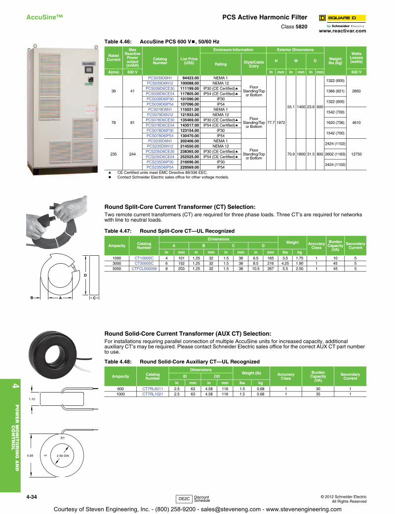
www.reactivar.com
4P
OW
ER
MO
NIT
OR
ING
AN
D
CO
NT
RO
L
4-34 © 2012 Schneider ElectricAll Rights Reserved
AccuSine™ PCS Active Harmonic FilterClass 5820
Round Split-Core Current Transformer (CT) Selection:Two remote current transformers (CT) are required for three phase loads. Three CT’s are required for networks with line to neutral loads.
Round Solid-Core Current Transformer (AUX CT) Selection:For installations requiring parallel connection of multiple AccuSine units for increased capacity, additional auxiliary CT’s may be required. Please contact Schneider Electric sales office for the correct AUX CT part number to use.
Table 4.46: AccuSine PCS 600 Vb, 50/60 Hz
RatedCurrent
Max Reactive
Power output (kVAR)
CatalogNumber
List Price(US$)
Enclosure Information Exterior Dimensions
Weightlbs (kg)
Watts Losses(watts)
Rating Style/Cable Entry
H W D
A(ms) 600 V In mm In mm In mm 600 V
39 41
PCS039D6N1 94423.00 NEMA 1
Floor Standing/Top
or Bottom
77.7 1972
55.1 1400 23.6 600
1322 (600)
2850
PCS039D6N12 100088.00 NEMA 12PCS039D6CE30 111199.00 IP30 (CE Certified)a
1366 (621)PCS039D6CE54 117805.00 IP54 (CE Certified)aPCS039D6IP30 101090.00 IP30
1322 (600)PCS039D6IP54 107096.00 IP54
78 81
PCS078D6N1 115031.00 NEMA 1
Floor Standing/Top
or Bottom
1542 (700)
4610
PCS078D6N12 121933.00 NEMA 12PCS078D6CE30 135469.00 IP30 (CE Certified)a
1620 (736)PCS078D6CE54 143517.00 IP54 (CE Certified)aPCS078D6IP30 123154.00 IP30
1542 (700)PCS078D6IP54 130470.00 IP54
235 244
PCS235D6N1 202406.00 NEMA 1
Floor Standing/Top
or Bottom70.9 1800 31.5 800
2424 (1102)
12750
PCS235D6N12 214550.00 NEMA 12PCS235D6CE30 238365.00 IP30 (CE Certified)a
2602 (1183)PCS235D6CE54 252525.00 IP54 (CE Certified)aPCS235D6IP30 216696.00 IP30
2424 (1102)PCS235D6IP54 229569.00 IP54
a CE Certified units meet EMC Directive 89/336 EEC.b Contact Schneider Electric sales office for other voltage models.
Table 4.47: Round Split-Core CT—UL Recognized
Ampacity CatalogNumber
DimensionsWeight Accuracy
Class
BurdenCapacity
(VA)
SecondaryCurrentA B C D
in mm in mm in mm in mm lbs kg
1000 CT1000SC 4 101 1.25 32 1.5 38 6.5 165 3.5 1.75 1 10 53000 CT3000SC 6 152 1.25 32 1.5 38 8.5 216 4.25 1.90 1 45 55000 CTFCL500058 8 203 1.25 32 1.5 38 10.5 267 5.5 2.50 1 45 5
Table 4.48: Round Solid-Core Auxiliary CT—UL Recognized
Ampacity CatalogNumber
DimensionsWeight (lb) Accuracy
Class
BurdenCapacity
(VA)
SecondaryCurrentID OD
in mm in mm lbs kg
600 CT7RL6011 2.5 63 4.58 116 1.5 0.68 1 30 11000 CT7RL1021 2.5 63 4.58 116 1.5 0.68 1 35 1
AB
D
C
1.10
H1 2.50 DIA
X1
4.58
DE2C Discount Schedule
Courtesy of Steven Engineering, Inc. - (800) 258-9200 - [email protected] - www.stevenengineering.com
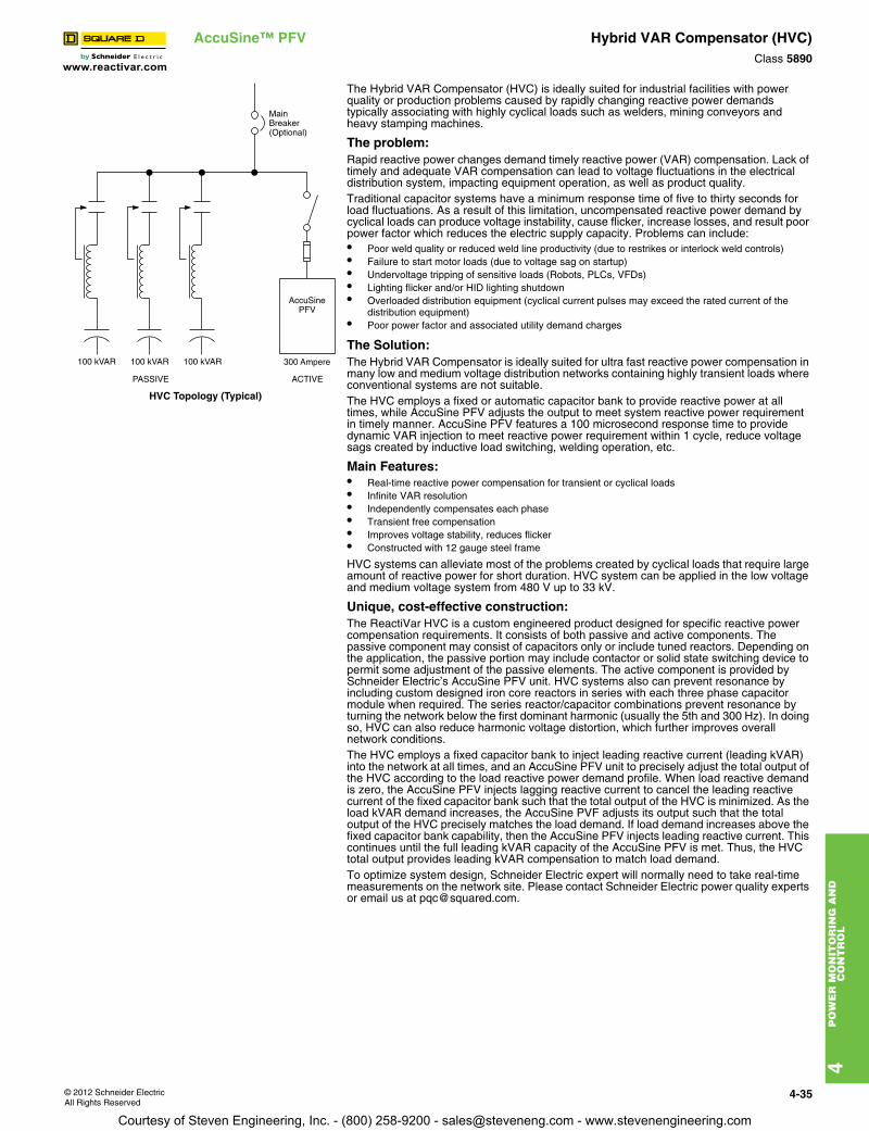
www.reactivar.com
4P
OW
ER
MO
NIT
OR
ING
AN
D
CO
NT
RO
L
© 2012 Schneider ElectricAll Rights Reserved
4-35
AccuSine™ PFV Hybrid VAR Compensator (HVC)Class 5890
The Hybrid VAR Compensator (HVC) is ideally suited for industrial facilities with power quality or production problems caused by rapidly changing reactive power demands typically associating with highly cyclical loads such as welders, mining conveyors and heavy stamping machines.
The problem:Rapid reactive power changes demand timely reactive power (VAR) compensation. Lack of timely and adequate VAR compensation can lead to voltage fluctuations in the electrical distribution system, impacting equipment operation, as well as product quality.Traditional capacitor systems have a minimum response time of five to thirty seconds for load fluctuations. As a result of this limitation, uncompensated reactive power demand by cyclical loads can produce voltage instability, cause flicker, increase losses, and result poor power factor which reduces the electric supply capacity. Problems can include:• Poor weld quality or reduced weld line productivity (due to restrikes or interlock weld controls)• Failure to start motor loads (due to voltage sag on startup)• Undervoltage tripping of sensitive loads (Robots, PLCs, VFDs) • Lighting flicker and/or HID lighting shutdown• Overloaded distribution equipment (cyclical current pulses may exceed the rated current of the
distribution equipment)• Poor power factor and associated utility demand charges
The Solution:The Hybrid VAR Compensator is ideally suited for ultra fast reactive power compensation in many low and medium voltage distribution networks containing highly transient loads where conventional systems are not suitable.The HVC employs a fixed or automatic capacitor bank to provide reactive power at all times, while AccuSine PFV adjusts the output to meet system reactive power requirement in timely manner. AccuSine PFV features a 100 microsecond response time to provide dynamic VAR injection to meet reactive power requirement within 1 cycle, reduce voltage sags created by inductive load switching, welding operation, etc.
Main Features:• Real-time reactive power compensation for transient or cyclical loads• Infinite VAR resolution• Independently compensates each phase• Transient free compensation• Improves voltage stability, reduces flicker• Constructed with 12 gauge steel frame
HVC systems can alleviate most of the problems created by cyclical loads that require large amount of reactive power for short duration. HVC system can be applied in the low voltage and medium voltage system from 480 V up to 33 kV.
Unique, cost-effective construction:The ReactiVar HVC is a custom engineered product designed for specific reactive power compensation requirements. It consists of both passive and active components. The passive component may consist of capacitors only or include tuned reactors. Depending on the application, the passive portion may include contactor or solid state switching device to permit some adjustment of the passive elements. The active component is provided by Schneider Electric’s AccuSine PFV unit. HVC systems also can prevent resonance by including custom designed iron core reactors in series with each three phase capacitor module when required. The series reactor/capacitor combinations prevent resonance by turning the network below the first dominant harmonic (usually the 5th and 300 Hz). In doing so, HVC can also reduce harmonic voltage distortion, which further improves overall network conditions.The HVC employs a fixed capacitor bank to inject leading reactive current (leading kVAR) into the network at all times, and an AccuSine PFV unit to precisely adjust the total output of the HVC according to the load reactive power demand profile. When load reactive demand is zero, the AccuSine PFV injects lagging reactive current to cancel the leading reactive current of the fixed capacitor bank such that the total output of the HVC is minimized. As the load kVAR demand increases, the AccuSine PVF adjusts its output such that the total output of the HVC precisely matches the load demand. If load demand increases above the fixed capacitor bank capability, then the AccuSine PFV injects leading reactive current. This continues until the full leading kVAR capacity of the AccuSine PFV is met. Thus, the HVC total output provides leading kVAR compensation to match load demand.To optimize system design, Schneider Electric expert will normally need to take real-time measurements on the network site. Please contact Schneider Electric power quality experts or email us at [email protected].
MainBreaker(Optional)
AccuSinePFV
300 Ampere
ACTIVEPASSIVE
100 kVAR 100 kVAR 100 kVAR
HVC Topology (Typical)
Courtesy of Steven Engineering, Inc. - (800) 258-9200 - [email protected] - www.stevenengineering.com
www.reactivar.com
4P
OW
ER
MO
NIT
OR
ING
AN
D
CO
NT
RO
L
4-36 © 2012 Schneider ElectricAll Rights Reserved
AccuSine™ PFV Hybrid VAR Compensator (HVC)Class 5890
Courtesy of Steven Engineering, Inc. - (800) 258-9200 - [email protected] - www.stevenengineering.com