table of contents section page - mdt.mt.gov · august 2002 bridge decks 15(i) table of contents...
TRANSCRIPT

August 2002 BRIDGE DECKS 15(i) Table of Contents
Section Page 15.1 BACKGROUND ....................................................................................................... 15.1(1) 15.1.1 Bridge Decks and Superstructures ........................................................ 15.1(1) 15.1.2 Durability of Concrete Bridge Decks ................................................... 15.1(1) 15.1.3 Protection of Reinforcing Bars ............................................................. 15.1(1) 15.2 “STRIP METHOD” .................................................................................................. 15.2(1) 15.2.1 Application of the “Strip Method” to Composite Concrete Decks ....... 15.2(1) 15.2.2 Typical Reinforcement ......................................................................... 15.2(1) 15.3 DESIGN DETAILS FOR BRIDGE DECKS ............................................................ 15.3(1) 15.3.1 General.................................................................................................. 15.3(1) 15.3.2 Dimensional Requirements for Concrete Decks................................... 15.3(1) 15.3.2.1 Slab Thickness .................................................................. 15.3(1) 15.3.2.2 Haunch Dimensions at Steel Beams and Girders .............. 15.3(1) 15.3.2.3 Haunch Dimensions for Concrete Beams ......................... 15.3(2) 15.3.3 Forms .................................................................................................... 15.3(2) 15.3.4 Skewed Decks....................................................................................... 15.3(2) 15.3.5 Deck Joints............................................................................................ 15.3(6)
15.3.5.1 Longitudinal Open Joints .................................................. 15.3(6) 15.3.5.2 Construction Joints............................................................ 15.3(6) 15.3.6 Deck Pours ............................................................................................. 15.3(7) 15.3.7 Expansion Joints..................................................................................... 15.3(7) 15.3.7.1 General .............................................................................. 15.3(7) 15.3.7.2 Asphaltic Plug ................................................................... 15.3(9) 15.3.7.3 Silicone Rubber Sealant .................................................... 15.3(9) 15.3.7.4 Strip Seal ........................................................................... 15.3(9) 15.3.7.5 Finger Plates...................................................................... 15.3(10) 15.3.7.6 Modular ............................................................................. 15.3(10) 15.3.7.7 Sliding Plates..................................................................... 15.3(10) 15.3.7.8 Example Problem .............................................................. 15.3(10)
15.3.8 Deck Drainage ...................................................................................... 15.3(11)
15(ii) BRIDGE DECKS August 2002
Table of Contents (Continued) Section Page
15.3.8.1 Hydraulic Analysis............................................................ 15.3(11) 15.3.8.2 General Practices............................................................... 15.3(11) 15.3.8.3 Downspouts....................................................................... 15.3(11)
15.4 MISCELLANEOUS STRUCTURAL ITEMS.......................................................... 15.4(1) 15.4.1 Structural Design of Overhangs ............................................................. 15.4(1) 15.4.1.1 General .............................................................................. 15.4(1) 15.4.1.2 Width................................................................................. 15.4(1) 15.4.1.3 Curved Bridges.................................................................. 15.4(1) 15.4.1.4 Construction Considerations for Steel Girder Bridges...... 15.4(1) 15.4.1.5 Deck Depth at Outside Edge ............................................. 15.4(1) 15.4.1.6 Concrete Barrier ................................................................ 15.4(3) 15.4.1.7 Collision Loads ................................................................. 15.4(3) 15.4.2 Design of Transverse Edge Beams......................................................... 15.4(3) 15.4.3 Design of Barriers .................................................................................. 15.4(4) 15.4.3.1 Concrete ............................................................................ 15.4(4) 15.4.3.2 Steel................................................................................... 15.4(4) 15.5 BRIDGE DECK APPURTENANCES...................................................................... 15.5(1) 15.5.1 Bridge Rails ............................................................................................ 15.5(1) 15.5.1.1 Test Levels ........................................................................ 15.5(1) 15.5.1.2 Bridge Rail Types/Usage .................................................. 15.5(1) 15.5.1.3 Guardrail-To-Bridge-Rail Transitions............................... 15.5(3) 15.5.1.4 Bridge Rail/Sidewalk ........................................................ 15.5(3) 15.5.2 Pedestrian Rails ...................................................................................... 15.5(4) 15.5.3 Bicycle Rails........................................................................................... 15.5(4) 15.5.4 Fences..................................................................................................... 15.5(4) 15.5.5 Utility Attachments ................................................................................ 15.5(7) 15.5.5.1 General .............................................................................. 15.5(7) 15.5.5.2 New Bridges...................................................................... 15.5(9) 15.5.5.3 Pipelines ............................................................................ 15.5(9) 15.5.5.4 Procedures ......................................................................... 15.5(9) 15.5.6 Sign Attachments ................................................................................... 15.5(9) 15.5.7 Lighting/Traffic Signals ......................................................................... 15.5(10)

August 2002 BRIDGE DECKS 15.1(1)
Chapter Fifteen BRIDGE DECKS
Sections 3, 4 and 9 of the LRFD Bridge Design Specifications present the AASHTO criteria for the structural design of bridge decks. Section 3 specifies loads for bridge decks, Section 4 specifies their analyses and Section 9 specifies the resistance of bridge decks. Unless noted otherwise in Chapter Fifteen of the Montana Structures Manual, the LRFD Specifications apply to the design of bridge decks in Montana. Chapter Fifteen presents information on MDT practices in the design of bridge decks. 15.1 BACKGROUND 15.1.1 Bridge Decks and Superstructures The LRFD Specifications encourage the integration of the deck with the primary components of the superstructure by either composite or monolithic action. In some cases, the deck alone is the superstructure. The LRFD Specifications call this a slab superstructure; MDT calls it a flat slab. More commonly, the deck in conjunction with its supporting components comprises the superstructure, leading to some confusion in definition. Chapter Fifteen of the Montana Structures Manual documents MDT criteria on the design of bridge decks which are constructed in conjunction with prestressed, precast concrete I-beams or composite steel I-beams. Chapter Sixteen discusses the design of reinforced, CIP concrete slabs. Also note that the LRFD Specifications have introduced the “empirical” deck design. Decks designed using the empirical design method are also sometimes called isotropically reinforced or Ontario-type decks. MDT is evaluating this design for potential future use in Montana.
15.1.2 Durability of Concrete Bridge Decks Reference: Various LRFD Articles As stated in the commentary to LRFD Article 2.5.2.1.1, the single most prevalent bridge maintenance problem is the deterioration of concrete bridge decks. Measures to enhance the durability of concrete components, in particular, are discussed in Article 5.12. The distress of bridge decks, and their premature replacement, has become a serious problem in the United States. In Article 1.2, the LRFD Specifications define the design life of new bridges to be 75 years. Thus, designers are compelled to re-evaluate conventional wisdom regarding the long-term performance of concrete bridge decks. 15.1.3 Protection of Reinforcing Bars In the presence of air and moisture, reinforcing steel corrodes, and the corrosion process is accelerated by salts. The corrosion product (i.e., rust) has a larger volume than the steel consumed, resulting in spalled areas at the top of the deck. There are a variety of methods to protect the reinforcing steel on new decks and to decelerate the rate of corrosion as identified below; however, Montana typical practice is to use epoxy-coated reinforcing steel in both mats of deck reinforcing combined with a minimum cover of 60 mm from the top surface of the deck to the top mat: 1. Epoxy-Coated, Galvanized, Stainless Steel/
Stainless Steel-Clad Reinforcing Steel. Retards corrosion of reinforcing steel.

15.1(2) BRIDGE DECKS August 2002 2. Waterproofing and Asphaltic Overlay.
Experience indicates that waterproofing cannot be made perfect and, by potentially trapping moisture, it may be counter-productive. MDT does not permit its usage except in special cases with advance approval of the Bridge Engineer.
3. Concrete Overlay (Latex-Modified). Be-
cause they are extremely impervious, they perform well on old decks but, because they are expensive, they are not always cost effective.
4. Additional Cement. This is an effective way of reducing permeability but, because of increasing shrinkage, can be counter-productive. MDT is monitoring nationwide developments in high-performance concrete (HPC) to evaluate its potential use in Montana.
5. Fly Ash. This moderately decreases
permeability, contributes to a gain in strength and improves concrete durability.
6. Microsilica. This is an effective internal
sealant but produces high hydration temperatures and plastic cracking.
7. Calcium Nitrate. This absorbs chloride by sacrificial chemical binding and, thus, delays but does not prevent migration of chloride ions.
8. Concrete Cover. The practical depth of
cover delays but does not prevent the chloride from reaching the steel bars.
9. Surface Sealants. Provides initial protection
of the deck. 10. Transverse Post-Tensioning. Minimizes
cracking. 11. Cathodic Protection. Retards corrosion of
reinforcing steel.
12. Bar Size. Smaller diameter bars for the same steel cross sectional area provide better crack-size control.
August 2002 BRIDGE DECKS 15.2(1) 15.2 “STRIP METHOD” 15.2.1 Application of the “Strip Method” to Composite Concrete Decks Reference: Appendix to LRFD Section 4 The application of the strip method to composite concrete decks is represented by a design aid in the Appendix to Section 4 of the LRFD Specifications, Table A4.1-1. An introduction to the Table discusses the limitations on its application. In lieu of a rigorous analysis, Figure 15.2A may be used to design the concrete deck reinforcement. Figure 15.2A tabulates the results of slab steel design traditionally used by MDT for Grade 420 reinforcing steel and concrete strengths of 28 MPa and 31 MPa. Because the calculations do not show a particular sensitivity to concrete strength, Figure 15.2A is appropriate for both concrete strengths. Figure 15.2A is based upon the AASHTO Standard Specifications for Highway Bridges. Rigorous application of the strip method generally results in slightly greater reinforce-ment requirements than presented in the Figure. Based upon satisfactory past performance and the fact that the “empirical” deck design method of the LRFD Specifications require less reinforcement than the “strip method,” designs in accordance with Figure 15.2A are deemed acceptable. Slab steel design as presented in Figure 15.2A attempts to balance the costs of concrete and reinforcing steel to produce an optimum design. 15.2.2 Typical Reinforcement Figure 15.2B presents the typical deck reinforcement designed in accordance with Figure 15.2A.

15.2(2) BRIDGE DECKS August 2002
28 MPa or 31 MPa Concrete
Min
. hau
nch
=
Min
imum
hau
nch
= Sl
ab +
20
mm
220
mm
(Sta
ndar
d)
SLAB STEEL DESIGN*
MAXIMUM BEAM SPACING (mm) #13 DIST. STEEL
I A IV M72 10A EFFECTIVE SPAN (mm)
SLAB T (mm)
TRANSVERSE STEEL (mm) 0.50 S 0.25 S
1676 1778 1880 1981 1969 1375 185 #16 @ 230 4 1
1753 1854 1956 2057 2045 1450 185 #16 @ 225 4 1
1803 1905 2007 2108 2096 1500 185 #16 @ 220 4 1
1854 1956 2057 2159 2146 1550 190 #16 @ 220 4 1 1930 2032 2134 2235 2223 1625 190 #16 @ 215 4 1
2007 2108 2210 2311 2299 1700 190 #16 @ 210 5 2
2057 2159 2261 2362 2350 1750 190 #16 @ 205 5 2
2134 2235 2337 2438 2426 1825 190 #16 @ 195 5 2
2184 2286 2388 2489 2477 1875 200 #16 @ 205 5 2
2235 2337 2438 2540 2527 1925 200 #16 @ 205 5 2
2311 2413 2515 2616 2604 2000 200 #16 @ 200 6 2
2388 2489 2591 2692 2680 2075 200 #16 @ 190 6 2 2464 2565 2667 2769 2756 2150 200 #16 @ 185 7 2
2565 2667 2769 2870 2858 2250 200 #16 @ 180 7 2 2692 2794 2896 2997 2985 2400 205 #16 @ 175 8 2
2794 2896 2997 3099 3086 2500 205 #16 @ 170 8 2
2870 2972 3073 3175 3162 2575 205 **#16 @ 165 9 3
2921 3023 3124 3226 3213 2625 205 **#16 @ 160 9 3
3023 3124 3226 3327 3315 2725 210 **#16 @ 160 9 3
3124 3226 3327 3429 3416 2825 210 **#16 @ 155 10 3
3200 3302 3404 3505 3493 2900 210 **#16 @ 150 11 3 3000 210 #19 @ 195 12 3
3100 210 #19 @ 190 13 4
3225 210 #19 @ 185 13 4
3375 215 #19 @ 185 14 4
3425 220 #19 @ 185 14 4
3525 220 #19 @ 180 15 4
3600 225 #19 @ 180 15 4
3650 230 #19 @185 15 4
3800 230 #19 @180 16 4
EFFECTIVE SPAN Steel Griders: S = C – ½ F ge Width Type I: S = C – (3043048( +
* This table is for ASTM A-615 Grade 60 steel and 28 MPa or 31 MPa concrete only.
**B2 barrier bars are #13. Notes: 1. Check haunch depth on steel structure and on sag
verticals. 2. Use same haunch depth for all spans.
Minimum Slab Thickness Type A: S = C – (406 Flange Width mm( mm165thanlessnotbut,)S
)T = Type IV: S = C – (50830 Type M72: S = C – (610 Type 10A: S = C – (597
SLAB STEEL DESIGN (Strip Method)
Figure 15.2A
}lan) )
) ) (4) (Flange Thickness) ) (Flange + Web) / 2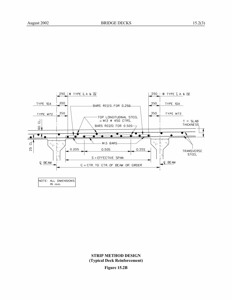
August 2002 BRIDGE DECKS 15.2(3)
STRIP METHOD DESIGN (Typical Deck Reinforcement)
Figure 15.2B

August 2002 BRIDGE DECKS 15.3(1) 15.3 DESIGN DETAILS FOR BRIDGE DECKS
15.3.1 General The following general criteria shall apply to bridge deck design: 1. Thickness. The depth of reinforced concrete
decks shall not be less than 165 mm. 2. Reinforcement Steel Strength. The specified
yield strength of reinforcing steel shall not be less than 420 MPa.
3. Reinforcement Cover. The bottom
reinforcement cover shall be a minimum of 25 mm. The top reinforcement cover shall be a minimum of 60 mm. The primary reinforcement shall be on the outside.
4. Rebar Spacing. The minimum spacing is
150 mm. The maximum spacing is 450 mm. 5. Minimum Rebar Size. This shall be #13. 6. Sacrificial Wearing Surface. The top 35 mm
of the bridge deck shall be considered sacrificial. Its weight must be included as a dead load but its structural contribution to the structure shall not be included in the structural design or as part of the composite section except for deflection calculations.
7. Concrete Strength. The specified 28-day
compressive strength of concrete for bridge decks shall be 28 MPa for Districts 3, 4 and 5, unless the District agrees to 31 MPa. This decision will be documented during the preliminary field review. In Districts 1 and 2, 31 MPa strength shall be specified.
8. Epoxy Coating. Epoxy coating shall be used
for all reinforcing steel in both top and bottom layers in bridge decks.
9. Length of Reinforcement Steel. The
maximum length of reinforcing steel in the deck shall be 12.19 m for #13 bars and 18.29 m for larger diameter bars.
10. Placement of Transverse Reinforcing on Skewed Bridges. The following applies:
a. Skews < 15°: Place the transverse
reinforcing steel parallel to the skew. Even at skews of less than 15˚, attempting to place transverse reinforce-ment on the skew may conflict with shear hoops on prestressed girders. Investigate and do not place transverse steel on the skew if it conflicts.
b. Skews > 15°: Place the transverse reinforcing steel perpendicular to the centerline of roadway or the long chord of the structure on curved bridges.
See Section 15.3.4 for structural
considerations related to skewed reinforcing placement.
11. Dead Load. For contingencies, add 0.50
kN/m2 to the dead load weight. 12. Splices/Connectors. Use lap splices for
deck reinforcement unless special circumstances exist. Mechanical connectors may be used where clearance problems exist or on a phase construction project that precludes the use of lap splices.
15.3.2 Dimensional Requirements for Concrete Decks 15.3.2.1 Slab Thickness Figure 15.2A presents standard deck slab thicknesses and required slab reinforcement for given beam spacings and Grade 420 reinforcing steel. 15.3.2.2 Haunch Dimensions for Steel
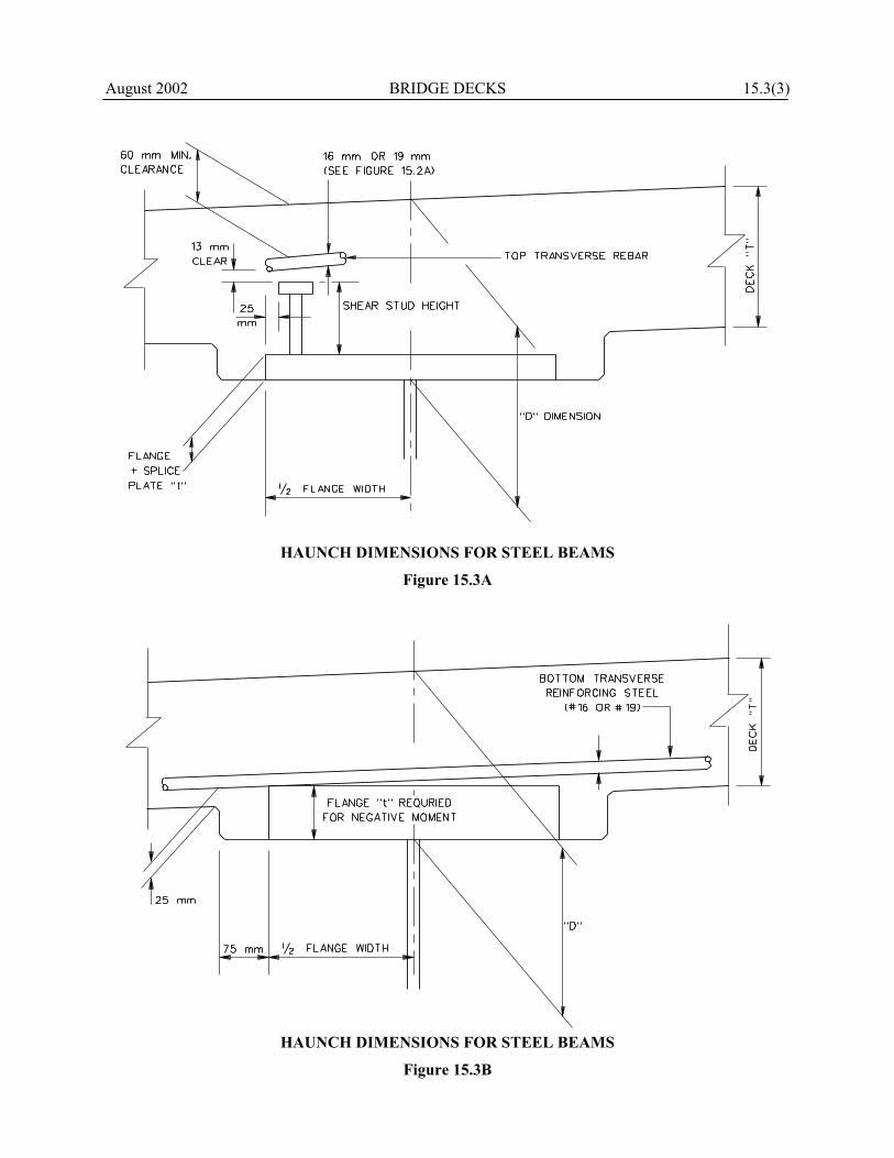
Girders Figures 15.3A and 15.3B illustrate the controlling factors used to determine the haunch dimensions for steel girders.
15.3(2) BRIDGE DECKS August 2002 The slab thickness is selected based on Figure 15.2A or the project-specific slab design. The first check is to determine the minimum “D” dimension that places the shear studs underneath the top mat of reinforcing steel. The second check determines the minimum “D” dimension that allows the transverse bottom reinforcement to clear the top flange of the girder and provide 25 mm of clearance to the bottom of the slab. The greater value of these two checks for the minimum “D” dimension controls. A value of “D” should be selected to the next higher 10 mm increment: 1. Control dimension “D” should be
established immediately after the top flange plate and after the splice plate thicknesses have been determined. In real world context, preliminary beam runs are usually sufficient, and it is not necessary to re-examine the issue after the final beam runs are made.
2. Control dimension “D” should be held
constant for all plate girders throughout the structure. For rolled girders, this dimension may vary along the span.
3. Once established, control dimension “D”
should be used for all elevation computations such as bridge seats, top of splice elevations, etc.
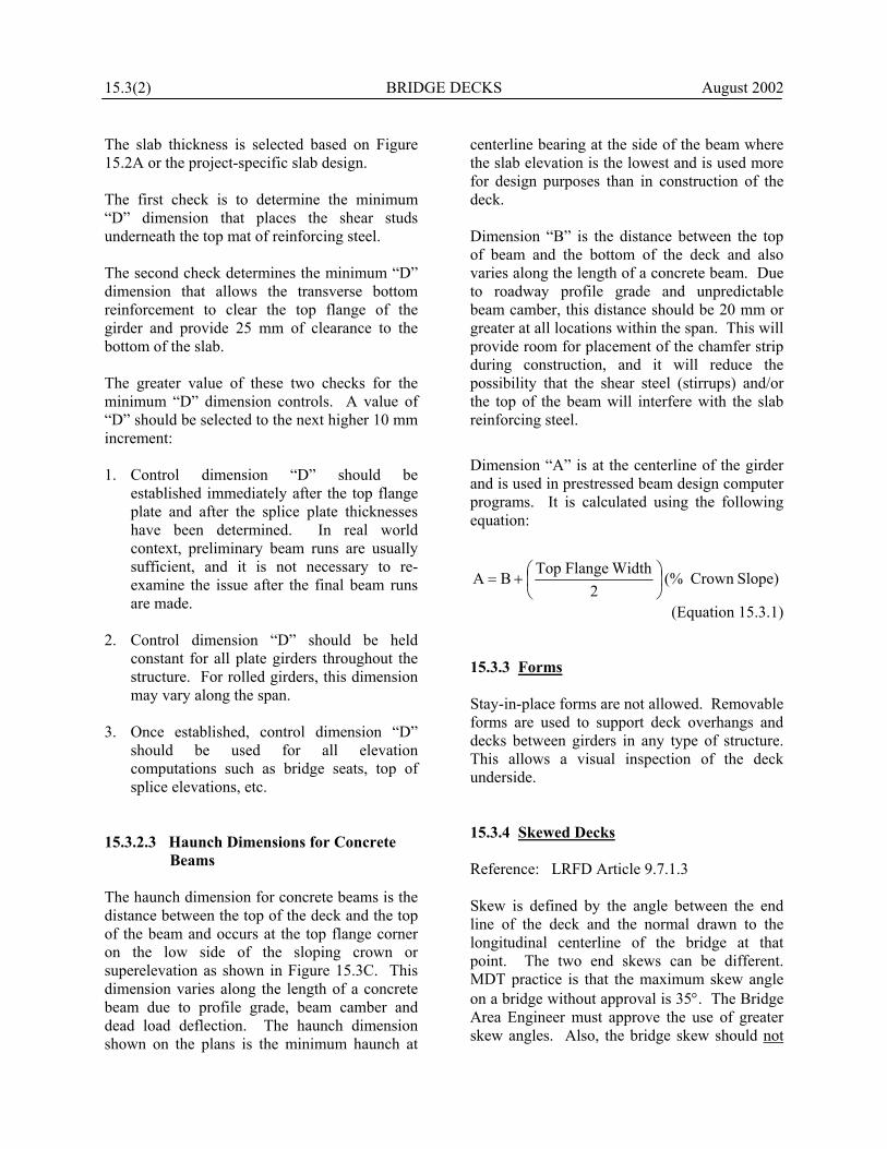
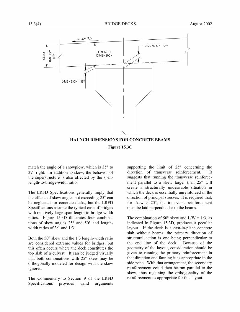
15.3.2.3 Haunch Dimensions for Concrete
Beams The haunch dimension for concrete beams is the distance between the top of the deck and the top of the beam and occurs at the top flange corner on the low side of the sloping crown or superelevation as shown in Figure 15.3C. This dimension varies along the length of a concrete beam due to profile grade, beam camber and dead load deflection. The haunch dimension shown on the plans is the minimum haunch at
centerline bearing at the side of the beam where the slab elevation is the lowest and is used more for design purposes than in construction of the deck. Dimension “B” is the distance between the top of beam and the bottom of the deck and also varies along the length of a concrete beam. Due to roadway profile grade and unpredictable beam camber, this distance should be 20 mm or greater at all locations within the span. This will provide room for placement of the chamfer strip during construction, and it will reduce the possibility that the shear steel (stirrups) and/or the top of the beam will interfere with the slab reinforcing steel.
Dimension “A” is at the centerline of the girder and is used in prestressed beam design computer programs. It is calculated using the following equation:
)SlopeCrown(%2
WidthFlangeTopBA
+=
(Equation 15.3.1) 15.3.3 Forms Stay-in-place forms are not allowed. Removable forms are used to support deck overhangs and decks between girders in any type of structure. This allows a visual inspection of the deck underside. 15.3.4 Skewed Decks Reference: LRFD Article 9.7.1.3 Skew is defined by the angle between the end line of the deck and the normal drawn to the longitudinal centerline of the bridge at that point. The two end skews can be different. MDT practice is that the maximum skew angle on a bridge without approval is 35°. The Bridge Area Engineer must approve the use of greater skew angles. Also, the bridge skew should not
August 2002 BRIDGE DECKS 15.3(3)
HAUNCH DIMENSIONS FOR STEEL BEAMS
Figure 15.3A
HAUNCH DIMENSIONS FOR STEEL BEAMS
Figure 15.3B
15.3(4) BRIDGE DECKS 2002
August
HAUNCH DIMENSIONS FOR CONCRETE BEAMS
Figure 15.3C
match the angle of a snowplow, which is 35° to 37° right. In addition to skew, the behavior of the superstructure is also affected by the span-length-to-bridge-width ratio. The LRFD Specifications generally imply that the effects of skew angles not exceeding 25° can be neglected for concrete decks, but the LRFD Specifications assume the typical case of bridges with relatively large span-length-to-bridge-width ratios. Figure 15.3D illustrates four combina-tions of skew angles 25° and 50° and length-width ratios of 3:1 and 1:3. Both the 50° skew and the 1:3 length-width ratio are considered extreme values for bridges, but this often occurs where the deck constitutes the top slab of a culvert. It can be judged visually that both combinations with 25° skew may be orthogonally modeled for design with the skew ignored. The Commentary to Section 9 of the LRFD Specifications provides valid arguments
supporting the limit of 25° concerning the direction of transverse reinforcement. It suggests that running the transverse reinforce-ment parallel to a skew larger than 25° will create a structurally undesirable situation in which the deck is essentially unreinforced in the direction of principal stresses. It is required that, for skew > 25°, the transverse reinforcement must be laid perpendicular to the beams. The combination of 50° skew and L/W = 1:3, as indicated in Figure 15.3D, produces a peculiar layout. If the deck is a cast-in-place concrete slab without beams, the primary direction of structural action is one being perpendicular to the end line of the deck. Because of the geometry of the layout, consideration should be given to running the primary reinforcement in that direction and fanning it as appropriate in the side zone. With that arrangement, the secondary reinforcement could then be run parallel to the skew, thus regaining the orthogonality of the reinforcement as appropriate for this layout.

August 2002 BRIDGE DECKS 15.3(5) COMBINATION OF SKEW ANGLE AND
SPAN LENGTH/BRIDGE WIDTH RATIOS
Figure 15.3D

15.3(6) BRIDGE DECKS August 2002 15.3.5 Deck Joints This Section discusses longitudinal open joints and deck construction joints in decks supported by girders. 15.3.5.1 Longitudinal Open Joints Reference: LRFD Article 14.5.1.1 Longitudinal open joints are not required in concrete bridge decks with widths of 27 m or less. For deck widths wider than 27 m, a longitudinal open joint may be used or a longitudinal closure pour, not less than 0.60 m wide, may be employed. Transverse steel lap splices shall be located within the longitudinal closure pour. Such a joint should remain open as long as the construction schedule permits to allow transverse shrinkage of the deck concrete. The designer should consider the deflections of each side of the bridge on either side of the closure pour to ensure proper transverse fit up. 15.3.5.2 Construction Joints Construction joints create planes of weakness that frequently cause maintenance problems. In general, deck construction joints are discouraged and their number should be minimized. 15.3.5.2.1 Longitudinal Construction Joints The following will apply to longitudinal construction joints: 1. Usage. Construction joints need not be used
on decks having a constant cross section where the width is less than or equal to 20 m. For deck widths greater than 20 m (i.e., where the screeding machine span width must exceed 20 m), the designer shall make provisions to permit placing the deck in practical widths.
2. Location. If a construction joint is
necessary, do not locate it underneath a
wheel line. Preferably, a construction joint should be located over a girder line.
15.3.5.2.2 Transverse Construction Joints The following will apply to transverse con-struction joints: 1. Steel Girder Structures. Concrete should be
placed continuously on steel girder structures with decks requiring up to a maximum of 125 m3 of concrete.
For longer structures that exceed the pour volume limitation of 125 m3, a slab pouring sequence should be considered in which the deck length is subdivided into segments at the points of final dead load contraflexure, with segments in positive flexure placed first and those in negative flexure last. See also Section 15.3.6.
2. Prestressed Concrete Structures. Prestressed
concrete girder bridges made continuous only for live load shall be treated as a special case. Transverse construction joints located 750 mm on each side of the pier centerline shall be provided. The short deck segment and diaphragm over the support provide continuity for live load in the superstructure after the previously poured center regions of the deck have been poured as simple span loads.
3. Location. Where used, transverse construc-
tion joints should be placed parallel to the transverse reinforcing steel.
4. Diaphragms. For prestressed concrete girder
bridges with cast-in-place decks, the LRFD Specifications require concrete diaphragms at the bearings.
5. Steel Structures. Place a transverse
construction joint in the end span of bridge decks on steel superstructures where uplift is a possibility during the deck pour. The condition most likely to produce that form of uplift is a bridge with an end span
August 2002 BRIDGE DECKS 15.3(7)
relatively short (60% or less) when compared to the adjacent interior span. Uplift during deck pour can also occur at end supports of curved decks and in superstructures with severe skews. If analysis shows that uplift might occur during a deck placement, require a construction joint in the end span and require placing a portion of the deck first to act as a counterweight.
6. End Supports. Live load in other spans can
produce uplift in short spans of continuous bridges. If analysis shows this condition may occur, include a counterweight or hold-down devices to counteract the effect. Show the details of these measures on the plans.
15.3.6 Deck Pours Reference: LRFD Article 2.5.3 The need for a slab pouring sequence in the bridge plans will be based on the volume of concrete in the bridge deck as follows: 1. Less than 75 m3 not needed. 2. 75 m3 to 125 m3 case-by-case decision. 3. Greater than 125 m3 required.
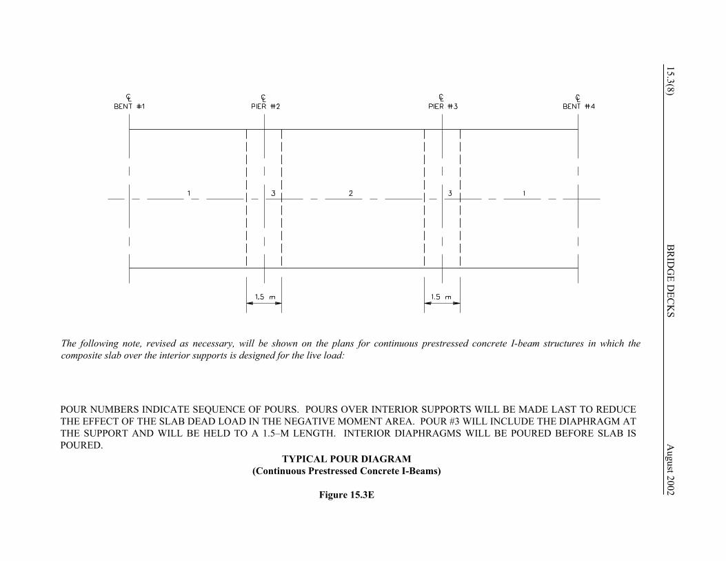
Where required, the bridge designer shall present in the bridge plans the sequence of placing concrete in various sections (separated by transverse construction joints) of deck slabs on continuous spans. The designated sequence shall avoid or minimize the dead load tensile stresses in the slab during concrete setting to minimize cracking, and it shall be arranged to cause the least disturbance to the portions placed previously. In addition, for longer span steel-girder bridges, the pouring sequence can lock-in stresses far different than those associated with the instantaneous placement typically assumed in design. Therefore, in these bridges, the designer should consider the pouring sequence in the design of the girders. Figure 15.3E illustrates a sample pour sequence diagram. Also, see Section 5.4.6.4 for guidance
on the presentation of the slab pouring sequence detail. 15.3.7 Expansion Joints Reference: LRFD Articles 14.4 and 14.5 Article 14.4 of the LRFD Specifications provides a discussion on the movements and loads on bridge joints, and Article 14.5 provides in-depth requirements for joints and considerations for specific joint types. The following presents MDT criteria for the use of expansion joints in bridge decks. Expansion length equals the distance from the expansion joint to the point of assumed zero movement. 15.3.7.1 General Expansion joints in bridge decks are often necessary to accommodate the expansion and contraction of bridges due to temperature variations. The following general criteria apply to all expansion joints in bridge decks: 1. Minimum Length. Because of their inherent
operational and maintenance problems, the desirable objective is to eliminate the need for expansion joints. Typically, a reasonably square bridge on flexible bents up to approximately 75 m in length may be constructed without expansion joints.
2. Maintenance Problems. Historically, most
of the maintenance problems on bridges in Montana result from failed joints. When a joint fails, this allows debris to fall on top of the bottom flanges and to accumulate on the tops of caps around shoes. This debris is frequently contaminated with chloride containing material and frequently remains moist for extended periods of time. Therefore, the proper selection and design of the expansion joint is a critical design issue. See the remainder of Section 15.3.7 for MDT guidance on selecting the type of expansion joint.
15.3(8) B
RID
GE D
ECK
S 20
August
02
The following note, revised as necessary, will be shown on the plans for continuous prestressed concrete I-beam structures in which thecomposite slab over the interior supports is designed for the live load:
POUR NUMBERS INDICATE SEQUENCE OF POURS. POURS OVER INTERIOR SUPPORTS WILL BE MADE LAST TO REDUCETHE EFFECT OF THE SLAB DEAD LOAD IN THE NEGATIVE MOMENT AREA. POUR #3 WILL INCLUDE THE DIAPHRAGM ATTHE SUPPORT AND WILL BE HELD TO A 1.5–M LENGTH. INTERIOR DIAPHRAGMS WILL BE POURED BEFORE SLAB ISPOURED.
TYPICAL POUR DIAGRAM (Continuous Prestressed Concrete I-Beams)
Figure 15.3E

August 2002 BRIDGE DECKS 15.3(9) 3. Temperature. Expansion joints shall be
designed to accommodate a temperature range of -40°C to 45°C.
4. Angles. If an angle or extruded shape larger
than 75 mm x 75 mm will be used to support an expansion joint, the angle must be supported from the top of the beam. Include a detail of the supporting device in the plans.
15.3.7.2 Asphaltic Plug This joint system is a smooth, durable, load-bearing surface using a combination of polymer-modified asphaltic binder and selected aggregate providing movement ranges up to 50 mm. Its advantages include no mechanical anchorage system, ease of placement, low maintenance and rideability. Its disadvantage include its non-flexibility in cold temperatures and its tendency to rut under heavy traffic in hot temperatures. 15.3.7.3 Silicone Rubber Sealant The silicone rubber sealant system can be used in joints that have movements up to 50 mm. The movement capacity of this type of joint is dictated by the joint width at the time of installation. The movement capacity is a function of the installation width plus and minus some percent of original gap size. One commonly used product, Dow Corning Product 902 RCS, recommends 100% for maximum opening and 50% for closing movement range; another production uses 50% for opening and closing. This type of joint is maintenance friendly in that local joint failures are easily mended. This system can be bonded to concrete, steel or polymeric elastic cement. 15.3.7.4 Strip Seal The strip seal expansion joint is the preferred deck expansion joint system for joint movements from 25 mm to 125 mm. Apply the following provisions when sizing a strip seal expansion joint:
1. Size expansion joints for each joint location within the bridge based on the calculated total joint movement. Joint movements are a function of:
a. girder materials and the coefficient of
thermal expansion, b. ambient temperature range of bridge
location, c. expansion length between points of
fixity and expansion, and d. longitudinal stiffness considerations of
substructure elements. 2. Select a joint from the manufacturer’s
information that provides the required range of movement for the joint being considered. To account for possible improper installation and uncertainty of estimated movements, LRFD Table 3.4.1-1 includes a load factor of 1.20 for the calculated movements due to uniform temperature, shrinkage and creep. With larger movements, this may be difficult to achieve with a strip seal because of the limited sizes of acceptable joint seals.
3. Provide the following plan details and
special provisions that identify the specific joint requirements to the contractor:
a. Show the minimum gap width at the
maximum temperature of the design range.
b. Show a table of temperature versus gap
width for various temperatures within the design range.
c. Show the gap width at the mean
temperature. d. Provide a factor indicating the
temperature change for 3 mm of joint movement.
15.3(10) BRIDGE DECKS August 2002
e. Check the opening at the anticipated installation temperature to see if it meets the manufacturer’s requirements.
15.3.7.5 Finger Plates This joint is applicable to anticipated movements greater than 125 mm. Typically, finger plates are only used on decks supported by steel girders. Finger plates allow debris to pass through; therefore, a collector trough is required underneath to catch the debris. Almost every collector trough detail is a high-maintenance item with marginal effectiveness. An alternative is to design the finger plate to simply spill all debris through and prepare details at the shoes so that the debris will not cause any adverse effects. However, despite its problems, a well-designed finger plate is perhaps the best design for large-movement joints. 15.3.7.6 Modular The LRFD Specifications recognizes that modular seals can be a high-maintenance joint by suggesting that consideration be given to modular seals that have been verified by long-term testing and designed to facilitate repair and replacement of components. Leakage, gland tears and broken welds in modular joints are common. Other States with more experience than Montana with modular joints also indicate problems on grades and in snow areas. Also, modular joints can only accommodate expansion and contraction, not rotation nor settlement. The LRFD Specifications include no design provisions for modular joints, because they are more like mechanical assemblies than individual components required to meet specific material or allowable stress requirements. The following will apply to the modular-type expansion joint:
1. Expansion Movement. The modular joint may only be considered where the anticipated expansion movement exceeds the length that can be accommodated by the strip seal expansion joints. For expansion movements greater than 125 mm, modular expansion joints may be advantageous. Its proposed use must be approved by the Bridge Design Engineer.
2. Splices. Where practical, modular joints
should be full length with no field splices across the roadway width. If a field splice is required for traffic continuity, the support beams should be spaced at a maximum of 600 mm from the splice location. The splice will be designed according to the manu-facturer’s recommendations.
3. Elastomeric Seal. The elastomeric seal will
be one piece across the roadway width, regardless of traffic continuity consider-ations and the presence of a field splice.
15.3.7.7 Sliding Plates Because of maintenance and operational problems, MDT does not prefer nor widely use sliding plates. For example, if the bridge requires jacking or grade adjustments, this has caused exceptional problems where sliding plates have been used. 15.3.7.8 Example Problem The end of Section 15.3 presents an example problem for the design of a strip seal expansion joint. 15.3.8 Deck Drainage Reference: LRFD Article 2.6.6

August 2002 BRIDGE DECKS 15.3(11) 15.3.8.1 Hydraulic Analysis In most cases, deck drains may be located intuitively (e.g., they are not needed on short bridges or where the bridge is on a crest vertical curve). Only in rare cases will it be necessary for the Hydraulics Section to perform a hydraulic analysis for the bridge deck drainage. This may be necessary where a barrier rail is used, the bridge length exceeds 50 m to 75 m, gradients are flat and/or the roadway shoulders are narrow. 15.3.8.1 General Practices To provide proper bridge deck drainage, the minimum longitudinal gradient is 0.2% for bridges with a barrier rail. For bridges with an open rail, the minimum is 0.0%, if there is adequate crown or superelevation to develop transverse drainage. Adequate drainage systems shall be provided for all bridge structures. The transverse drainage of the bridge deck should be handled by providing a suitable roadway cross slope. See Section 13.5. Longitudinal drainage in a gutter section should be intercepted and not permitted to run onto the traveled way portion of the bridge. Short bridges may be constructed without drainage inlets, and the water from the bridge roadway may be transported downslope to roadway embankment protectors near the end of the bridge structure. Longitudinal drainage on long bridges shall be handled by using drainage inlets of sufficient size and number to drain the gutters adequately. For drain details, refer to the MDT Bridge Standard Drawings. 15.3.8.2 Downspouts Downspouts, where required, should be of a rigid, corrosion-resistant material not less than 100 mm in diameter. Deck drainage and downspouts should be designed to prevent the discharge of drainage water against any portion of the structure and to prevent erosion at the outlet of the downspout. Also locate
downspouts to avoid discharge onto traffic below or onto railroad tracks or ballast. Overhanging portions of the concrete deck shall be provided with a drip groove. For downspout details, refer to the MDT Standard Bridge Details and Notes.

15.3(12) BRIDGE DECKS August 2002
Example Problem Strip Seal Expansion Joint Given: Prestressed concrete girders supporting reinforced concrete slab. Estimated movement due to uniform temperature. Use coefficients of thermal expansion
as given in LRFD Articles 5.4.2.2 and 6.4.1: L = 70 M ∆t = 80°C (TU) = (70 m) (80°C) (10.8 x 10⁻⁶/C°) (1000 mm/m) (TU) = 60 mm (30 mm contraction, 30 mm expansion) Note: TU is a function of the span and bearing configuration. It is equal to the
length from the fixed point to the strip seal times the total change in temperature times the coefficient of thermal expansion.
Neglect creep (CR) due to elastic shortening and shrinkage (SH). Problem: Determine expansion joint movement requirements. Solution: Total factored movement = 1.20 (TU) (LRFD Table 3.4.1-1) Total factored movement = 1.20 (60 mm) = 72 mm A strip seal is acceptable because the total factored movement is within the range for strip
seals (Section 15.3.7.4). Movements from mean temperature:
Factored contraction = 1.20 (30 mm) = 36 mm Factored expansion = 1.20 (30 mm) = 36 mm
Joint openings @ 40°C = 50 mm (minimum gap) 20°C = 68 mm (maximum installation temperature) 0°C = 86 mm -20°C = 104 mm -40°C = 50 mm (minimum gap) + 72 mm (total factored
movement) = 122 mm ∆T for 3 mm of factored movement = 3.33°C

August 2002 BRIDGE DECKS 15.4(1) 15.4 MISCELLANEOUS STRUCTURAL
ITEMS 15.4.1 Structural Design of Overhangs Reference: LRFD Article 9.7.1.5 15.4.1.1 General A 10-mm, double chamfer drip groove shall be placed 50 mm in from the edge of the slab. Once the controlling depth of the edge of the slab is determined, that depth should be used over the full length of the superstructure along that side of the bridge. The edge of the slab along the opposite side of a structure that is symmetrical about its centerline should be the same depth. The dimensions for the edge of slab depth are typically shown on the standard slab drawings for slabs supported by prestressed concrete beams. For the edge-of-slab depth on slabs supported by steel girders, refer to Figure 15.4A. 15.4.1.2 Width Deck overhang width is defined as the distance from the centerline of the exterior beam to the edge of the deck. For bridges supported by prestressed concrete beams, the overhang dimensions are standardized, and that dimension is indicated on the standard slab drawings. For bridge slabs supported on steel girders, the overhang width restrictions are the more restrictive of the following criteria: 1. not more than 0.30 to 0.35 times the beam
spacing to balance moments in interior and exterior beams,
2. not more than the depth of the beam, or 3. not more than 1200 mm.
15.4.1.3 Curved Bridges For curved bridge decks on bridges with straight girders, the limits on maximum overhang widths in Section 15.4.1.2 should be interpreted as the average within a span. On curved deck layouts, the distance from the centerline of the girder to the edge of the slab along both sides of the slab should be shown in a Slab Offset Diagram. These offsets should be shown at tenth points measured along the centerline of the exterior girder. The offset at all break points in roadway geometrics such as beginnings of flares or turning radii along the girder line should also be shown. 15.4.1.4 Construction Considerations for
Steel Girder Bridges Because of the geometry of construction brackets used to support the overhangs, it is preferable that the bottom of the slab be made flush with the underside of the top flange on steel structures and be sloped upward 10 mm towards the edge of the slab or, at the very least, be made level. To achieve this, it may be necessary to increase Control Dimension “D,” as discussed in Section 15.3.2 (Figure 15.3A), by increasing the haunch depth over the beam. If a greater Dimension “D” is established at the outside girder to control the slope of the bottom of the overhang, that dimension should be maintained at all girders throughout the structure. 15.4.1.5 Deck Depth at Outside Edge The depth of the outside edge of the deck for steel bridges will be different than the deck thickness. See Figure 15.4A. This is true for both superelevated bridges and bridges with normal crowns. The edge of slab depth selected at each side should be maintained over the full length of the superstructure along that side.

15.4(2) B
RID
GE D
ECK
S
August 2002
STEEL GIRDER OVERHANG TREATMENTS
Figure 15.4A
August 2002 BRIDGE DECKS 15.4(3) With beam flange width known from previous beam runs and “D” established based on Section 15.3.2.2, use the following procedure with Figure 15.4A to determine the deck thickness at the outside edge of the bridge: 1. Assume a value for T. 2. Find or assume an elevation for Point A (top
of exterior girder web). 3. Calculate: Elevation B = Elevation A + D +/− ((W - 420)e) − T
Notes: Use 350 instead of 420 for T101 rail. Express “e” as a decimal. For bridges with normal crown sections, e = typical cross slope, usually 0.02.
4. Perform check. Elevation B − Elevation A
must be between 0 and 10 (Section 15.4.1.4). If not, adjust T or D as needed to meet requirements.
15.4.1.6 Concrete Barrier Reference: LRFD Article 3.6.1.3.4 The LRFD Specifications allows the structural contribution of any structurally continuous barrier to be used to resist transient loads at the service and fatigue-and-fracture limit states. This is typically not done in Montana but may be considered in rehabilitation if the contribution of the barrier is significant. 15.4.1.7 Collision Loads Reference: LRFD Article A13.3.1 The design approach, as reflected by the LRFD Specifications, is that the collision loads are not specified and that the overhangs are designed for the force effects generated and transmitted by the barrier resisting the vehicular impact in a fully inelastic state. In other words, an over-
design of the barrier would automatically result in an unnecessary over-design of the overhang. This over-design would increase the amount of top steel in the deck overhang. MDT experience is that slabs designed in accordance with Figure 15.2A have a long history of satisfactory performance and need not be investigated further for collision loads. There are basically three ways by which the force effects transmitted to the overhang can be controlled: 1. reducing the barrier strength to the required
minimum, 2. improving the longitudinal distribution of
the collision force by barrier design, and/or 3. mitigating the transmitted force effect at the
barrier-deck interface. Such control, in conjunction with concrete barriers, can be exercised by the judicious proportioning of reinforcing steel in the barrier. Equations A13.3.1-1 through A13.3.1-4 in the LRFD Specifications indicate that the critical length of the failure pattern (LC), which is part of the total distribution length at the barrier-to-overhang interface, increases as the longitudinal steel increases and as the transverse (vertical) steel decreases, and that the resistance of the barrier increases with “LC”. There is a normal concentration of force effects in the end zone of the barrier, and the deck may need strengthening therein. An extension of the end beam (hidden or otherwise) to the barrier may be necessary to strengthen the overhang. 15.4.2 Design of Transverse Edge Beams Reference: LRFD Article 9.7.1.4 For prestressed, precast girders, a transverse edge beam is required.
15.4(4) BRIDGE DECKS August 2002 15.4.3 Design of Barriers Reference: LRFD Article 13.7.3.1 Section 15.5 discusses the types of bridge rails used by the Department. Section 15.4.3 discusses the structural design of concrete and steel barriers at the edges of bridges. 15.4.3.1 Concrete Concrete barrier railings will be built monolithically and continuous with no contraction joints at either mid-span or over the interior supports. To help control cracking, full-depth double chamfer strips are installed at 3000-mm intervals. Full-depth open joints will be provided only between the end of the structure and the concrete bridge approach and at expansion joints on structures. Stirrups connecting any continuously placed (whether or not structurally continuous) concrete barrier, curb, parapet, sidewalk or median to the concrete decks should be determined assuming full composite action at the interface, according to the provisions of Article 5.8.4 of the LRFD Specifications. 15.4.3.2 Steel For steel rails, the control in force effect transmission is attained by the appropriate proportioning of the post anchor bolts. In selecting the bolt material, ductility should be viewed as more important than strength. The design may facilitate the replacement of damaged bolts. Punching shear failure around the base of the post or below a concrete barrier, a brittle fracture mechanism that is difficult to rehabilitate, should be prevented. Slabs are constructed with additional reinforcement at post locations.
August 2002 BRIDGE DECKS 15.5(1) 15.5 BRIDGE DECK APPURTENANCES 15.5.1 Bridge Rails Reference: LRFD Article 13.7 15.5.1.1 Test Levels Reference: LRFD Article 13.7.2 Article 13.7.2 of the LRFD Specifications identifies six test levels for bridge rails, which have been adopted from NCHRP 350 Recommended Procedures for the Safety Performance Evaluation of Highway Features. Test Levels One, Two, Five A, Five and Six have no application in Montana. The following identifies the general test level application for TL-3 and TL-4: 1. TL-3 (Test Level Three). Generally
acceptable for a wide range of high-speed arterial highways with very low mixtures of heavy vehicles and with favorable site conditions. Performance crash testing is at 100 km/h with an 820-kg passenger car and a 2000-kg pickup truck.
2. TL-4 (Test Level Four). Generally
acceptable for the majority of applications on high-speed highways, freeways, expressways, and Interstate highways with a mixture of trucks and heavy vehicles. Performance crash testing is at 100 km/h with an 820-kg passenger car and a 2000-kg pickup truck plus an 8000-kg single-unit truck at 80 km/h.
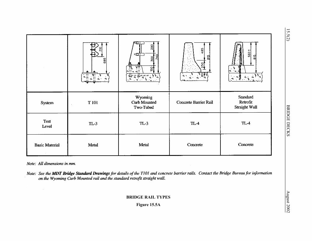
Note that, on the NHS, TL-3 is the minimum type bridge rail. 15.5.1.2 Bridge Rail Types/Usage Figure 15.5A presents the bridge rail types approved for use by MDT. The selection of a bridge rail type will be made on a case-by-case basis considering the following factors:
1. District preference, 2. snow removal, 3. highway functional classification, 4. traffic volumes, 5. truck volumes, 6. design speed, 7. geometrics, 8. urban/rural location, 9. aesthetics, 10. in-service performance, 11. life-cycle costs, 12. consequences of rail penetration, and 13. adaptability of the guardrail-to-bridge-rail
transition from the approaching roadway. MDT has not adopted rigid criteria for the selection of bridge rail types. The following provides general guidance for those rails presented in Figure 15.5A: 1. Concrete Barrier Rail. The concrete barrier
rail, which has the same face configuration as the concrete median barrier, is 815 mm in height, and its test level is TL-4. The rail’s advantages include its superior performance when impacted by large vehicles, its relatively low maintenance costs and its better compatibility with the bridge deck system (i.e., the concrete rail can be constructed integrally with the bridge deck). The concrete barrier rail’s disadvantages include its higher initial cost, higher dead weight and its hindrance to snow removal operations. The concrete rail is the only bridge rail allowed on current Interstate construction. It is often used on other major arterials in Montana (e.g., where the ADT >
15.5(2) B
RID
GE D
ECK
S
August 2002
BRIDGE RAIL TYPES
Figure 15.5A
August 2002 BRIDGE DECKS 15.5(3)
3000) and occasionally on urban facilities. See the MDT Bridge Standard Drawings for details on the concrete barrier rail design.
2. T101. The T101 bridge rail is 685 mm in height, and its test level is TL-3. The design originated in Texas and was developed and tested as the Texas 101 Rail. When compared to the concrete barrier rail, the T101’s advantages include better snow removal characteristics, lower initial cost, lower dead weight and providing a more open view of the surrounding countryside. The comparative disadvantages include a lesser ability to contain heavier vehicles, higher maintenance costs and a poorer structural connection to the bridge deck system. The T101 bridge rail is often used on lower level State highways and on bridges off the State highway system. See the MDT Bridge Standard Drawings for details on the T101 design.
3. Wyoming Curb-Mounted Two-Tube. The
Wyoming bridge rail is 740 mm in height, and its test level is TL-3. It is used in special circumstances only (e.g., where the District believes that snow removal is a special problem).
4. Brush Curbs. Where requested by the local
community, a 150-mm high concrete brush curb may be used on very low-volume, low-speed bridges where the use of a traditional bridge rail would require disassembling oversized, agricultural equipment to allow its passage across the bridge.
15.5.1.3 Guardrail-To-Bridge-Rail
Transitions The Road Design Section is responsible for designing the guardrail-to-bridge-rail transition for the approaching roadway. However, site conditions may present problems for the necessary transition. Therefore, the bridge designer should ensure compatibility between the bridge rail transition and the site when selecting the bridge rail type.
15.5.1.4 Bridge Rail/Sidewalk Reference: LRFD Articles 13.4 and 13.7.1.1 Section 13.5.4 discusses warrants for a sidewalk on a bridge. When a sidewalk is present, the location of the bridge rail requires additional consideration. Consider pedestrian safety, bridge rail performance, design speed, drainage requirements and sight distance of approaches adjacent to the ends of the bridge. The following will apply to the location of a bridge rail in combination with a sidewalk: 1. V ≤ 70 km/h. A sidewalk may be separated
from the adjacent roadway by a barrier curb. Barrier curbs are typically 150 mm to 200 mm high with steep faces. A raised sidewalk incorporating a barrier curb is typical in urban areas with curb and gutter sections approaching the bridge. The use of a barrier curb requires a combination bridge rail and pedestrian/bicycle rail at the outside edge of the sidewalk.
2. V ≥ 80 km/h. For high speeds, place a
traffic barrier between pedestrians and traffic; i.e., between the roadway and the sidewalk. A pedestrian/bicycle rail is then used at the outside edge of the sidewalk.
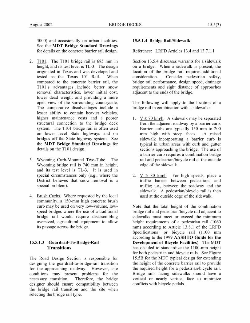
Note that the total height of the combination bridge rail and pedestrian/bicycle rail adjacent to sidewalks must meet or exceed the minimum height requirements of a pedestrian rail (1060 mm) according to Article 13.8.1 of the LRFD Specifications) or bicycle rail (1100 mm according to the 1999 AASHTO Guide for the Development of Bicycle Facilities). The MDT has decided to standardize the 1100-mm height for both pedestrian and bicycle rails. See Figure 15.5B for the MDT typical design for extending the height of the concrete barrier rail to provide the required height for a pedestrian/bicycle rail. Bridge rails facing sidewalks should have a vertical or nearly vertical face to minimize conflicts with bicycle pedals.

15.5(4) BRIDGE DECKS August 2002 15.5.2 Pedestrian Rails Reference: LRFD Article 13.8 If a sidewalk is placed on a bridge where the design speed is greater than or equal to 80 km/h, a bridge rail shall be used to separate the vehicular traffic from pedestrians and then use a pedestrian rail on the outside edge of the sidewalk. See Section 15.5.1.4. On facilities with sidewalks on bridges and where V ≤ 70 km/h, this arrangement will be considered on a case-by-case basis. The following factors will be evaluated: 1. design speed; 2. pedestrian volumes; 3. vehicular traffic volumes; 4. accident history; 5. geometric impacts (e.g., sight distance); 6. practicality of providing proper end
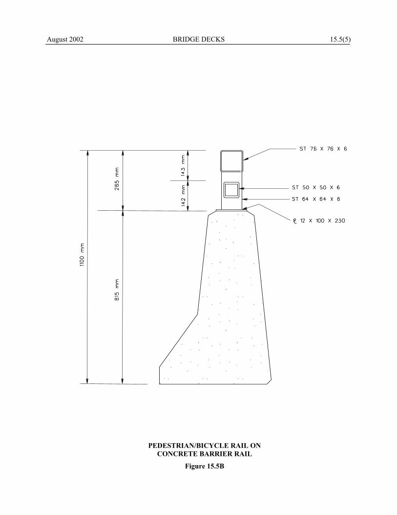
treatments; 7. construction costs; and 8. local preference. Regardless of the location of the bridge rail on bridges with sidewalks, the bridge rail shall include a pedestrian rail to a minimum height of 1100 mm. See Figure 15.5B. Figure 15.5C presents the MDT typical design for a pedestrian rail. 15.5.3 Bicycle Rails Reference: LRFD Article 13.9 The rail in Figure 15.5C satisfies the requirements for a bicycle rail. The following will apply:
1. Bicycle Paths. These are defined as a bikeway physically separated from motorized vehicular traffic by an open space or barrier and either within the highway right-of-way or within an independent right-of-way. Bridges which are part of a bicycle path will require a bicycle rail.
2. Other Facilities. On facilities where
bicycles use the roadway with considerable frequency, it may be warranted to provide a bicycle rail across the bridge. This may either be a separate bicycle rail on the outside of the bridge where the bridge rail separates the vehicular and bicycle traffic, or a height extension to a minimum of 1100 mm on top of the bridge rail where the bridge rail is on the outside of the bridge. The need for a bicycle rail will be considered on a case-by-case basis. The following factors will be evaluated:
a. design speed; b. bicycle volumes;
c. vehicular traffic volumes; d. accident history; e. geometric impacts (e.g., sight distance); f. practicality of providing proper end
treatments; g. construction costs; and h. local preference.
15.5.4 Fences Protective fencing across bridges is warranted as follows: 1. on all overpasses in urban areas with
sidewalks; 2. on other overpasses frequently used by
children (e.g., near schools or playgrounds).
August 2002 BRIDGE DECKS 15.5(5)
PEDESTRIAN/BICYCLE RAIL ON
CONCRETE BARRIER RAIL
Figure 15.5B
15.5(6) BRIDGE DECKS August 2002
PEDESTRIAN/BICYCLE RAIL
Figure 15.5C
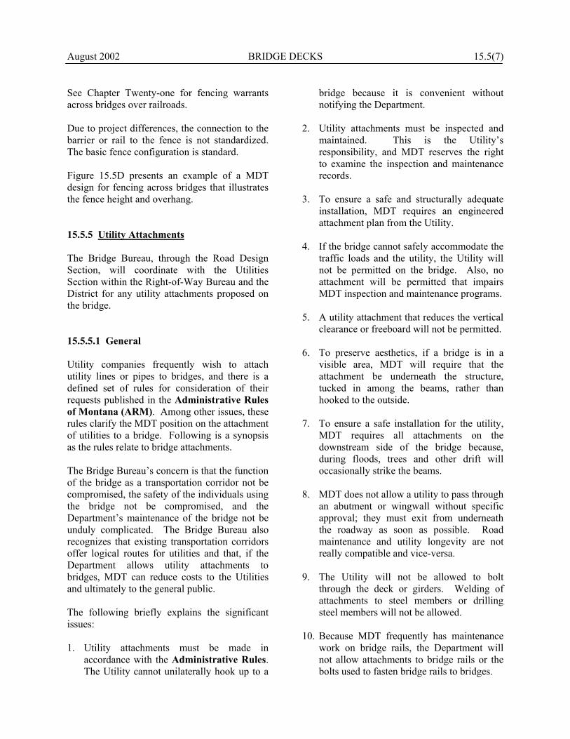
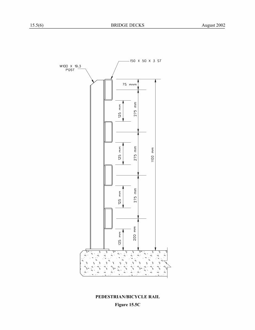
August 2002 BRIDGE DECKS 15.5(7) See Chapter Twenty-one for fencing warrants across bridges over railroads. Due to project differences, the connection to the barrier or rail to the fence is not standardized. The basic fence configuration is standard. Figure 15.5D presents an example of a MDT design for fencing across bridges that illustrates the fence height and overhang. 15.5.5 Utility Attachments The Bridge Bureau, through the Road Design Section, will coordinate with the Utilities Section within the Right-of-Way Bureau and the District for any utility attachments proposed on the bridge. 15.5.5.1 General Utility companies frequently wish to attach utility lines or pipes to bridges, and there is a defined set of rules for consideration of their requests published in the Administrative Rules of Montana (ARM). Among other issues, these rules clarify the MDT position on the attachment of utilities to a bridge. Following is a synopsis as the rules relate to bridge attachments. The Bridge Bureau’s concern is that the function of the bridge as a transportation corridor not be compromised, the safety of the individuals using the bridge not be compromised, and the Department’s maintenance of the bridge not be unduly complicated. The Bridge Bureau also recognizes that existing transportation corridors offer logical routes for utilities and that, if the Department allows utility attachments to bridges, MDT can reduce costs to the Utilities and ultimately to the general public. The following briefly explains the significant issues: 1. Utility attachments must be made in
accordance with the Administrative Rules. The Utility cannot unilaterally hook up to a
bridge because it is convenient without notifying the Department.
2. Utility attachments must be inspected and
maintained. This is the Utility’s responsibility, and MDT reserves the right to examine the inspection and maintenance records.
3. To ensure a safe and structurally adequate
installation, MDT requires an engineered attachment plan from the Utility.
4. If the bridge cannot safely accommodate the
traffic loads and the utility, the Utility will not be permitted on the bridge. Also, no attachment will be permitted that impairs MDT inspection and maintenance programs.
5. A utility attachment that reduces the vertical
clearance or freeboard will not be permitted. 6. To preserve aesthetics, if a bridge is in a
visible area, MDT will require that the attachment be underneath the structure, tucked in among the beams, rather than hooked to the outside.
7. To ensure a safe installation for the utility,
MDT requires all attachments on the downstream side of the bridge because, during floods, trees and other drift will occasionally strike the beams.
8. MDT does not allow a utility to pass through
an abutment or wingwall without specific approval; they must exit from underneath the roadway as soon as possible. Road maintenance and utility longevity are not really compatible and vice-versa.
9. The Utility will not be allowed to bolt
through the deck or girders. Welding of attachments to steel members or drilling steel members will not be allowed.
10. Because MDT frequently has maintenance
work on bridge rails, the Department will not allow attachments to bridge rails or the bolts used to fasten bridge rails to bridges.

15.5(8) BRIDGE DECKS 2002
August
FENCING ON BRIDGES
Figure 15.5D

August 2002 BRIDGE DECKS 15.5(9) 11. Trenching operations that are so close to the
bridge footings so that there may be undercutting or sloughing will not be allowed.
12. The Bridge Bureau is not the final approval
authority for attachments to historic bridges; these must be cleared with other agencies as well.
13. The Utility is responsible for any damage
resulting from the presence of the utility on the bridge.
14. Because certain areas in Montana are
recognized earthquake areas, the Department must be critical of allowing product lines on bridges that have not been built or retrofitted to seismic design codes.
15.5.5.2 New Bridges In addition to the above factors, the following applies to proposed utility attachments to new bridges: 1. If MDT must make a bridge stronger to
support a utility, the Utility must pay for the additional design and construction costs.
2. Installation of the utility should not interfere
with the MDT contractor constructing the bridge.
3. Utility facilities may pass through free-
standing abutments, but not one that moves with temperature changes.
15.5.5.3 Pipelines The following specifically applies to proposed pipelines on bridges: 1. For a pipeline installation to be approved, it
must either be cased or extra strong. The design factors listed in the ARM are consistent with safety factors commonly used in bridge design. If the Utility
proposes to meet the required design factors by using higher strength pipe, MDT will require certificates on the high-strength pipe.
2. The attachment shall be designed to prevent
discharge of the pipe product into the stream or river in case of pipe failure.
3. Using bridge members to resist forces
caused by moving fluids will not be permitted.
15.5.5.4 Procedures The following briefly describes the procedures for proposed utility attachments to bridges: 1. The Utility company notifies the District
Office of its desire to attach a utility to the structure and provides a proposed design for the attachment.
2. The Utility wishing to make the attachment
prepares Form RW20S and submits the package to the District. After review, the District forwards the proposal to the Utility Section for transmittal to the Bridge Bureau.
3. The Bridge Bureau reviews the proposal
from a structural adequacy perspective and, if in agreement, signs Form RW20S.
4. The Environmental Services Office reviews
the proposal from an environmental perspective and, if in agreement, signs Form RW20S.
5. The approved utility attachment design is transmitted back to the Utility company through the District Office.
15.5.6 Sign Attachments If the Signing Unit within the Traffic Engineering Section proposes to attach a sign to a bridge, the Unit must coordinate with the Bridge Bureau. The Bridge Bureau will assess the structural impact on the bridge and, if the

15.1(10) BRIDGE DECKS August 2002 sign attachment is approved, the Bureau will design the attachment details. 15.5.7 Lighting/Traffic Signals The Electrical Unit within the Traffic Engineering Section determines the warrants for highway lighting and traffic signals, and the Unit performs the design work to determine, for example, the spacing of the luminaries and the provision of electricity. In most cases, lighting will be included on bridges that are located in urban areas if requested by local officials; traffic signal warrants are determined on a case-by-case basis. Where included, the Bridge Bureau will design the structural support details for the luminaire and/or traffic signal attachments to the bridge.