table of contents - smogtech institute · table of contents pearson c u s t om librar y ,...
TRANSCRIPT
Table of Contents
P E A R S O N C U S T O M L I B R A R Y
I
1. Shop Safety1James D. Halderman
2. Environmental and Hazardous Materials9James D. Halderman
3. Vehicle Lifting and Hoisting21James D. Halderman
4. Hybrid Safety and Service Procedures29James D. Halderman
5. Gasoline Engine Operation, Parts and Specifications41James D. Halderman
6. Engine Condition Diagnosis55James D. Halderman
7. Diesel Engine Operating Principles71Gus Wright
8. Coolant91James D. Halderman
9. Cooling System Operation and Diagnosis99James D. Halderman
10. Intake and Exhaust Systems117James D. Halderman
11. Electrical Fundamentals127James D. Halderman
12. Electrical Circuits and Ohm’s Law137James D. Halderman
13. Series, Parallel, and Series-Parallel Circuits145James D. Halderman
000200010271942321_HALDER_Keiser1_STI_1p.pdf 3 12/4/2014 12:44:39 PM

II
14. Circuit Testers and Digital Meters157James D. Halderman
15. Wiring Schematics and Circuit Testing175James D. Halderman
16. Ignition System Components and Operation191James D. Halderman
17. Ignition System Diagnosis and Service205James D. Halderman
18. Turbocharging and Supercharging225James D. Halderman
19. Computer Fundamentals237James D. Halderman
20. Fuel Injection Components and Operation245James D. Halderman
21. Gasoline Direct Injection Systems257James D. Halderman
22. Temperature Sensors263James D. Halderman
23. Throttle Position Sensors273James D. Halderman
24. MAP/BARO Sensors279James D. Halderman
25. Mass Air Flow Sensors289James D. Halderman
26. On-Board Diagnosis297James D. Halderman
27. Evaporative Emission Control Systems307James D. Halderman
28. Exhaust Gas Recirculation (EGR) Systems317James D. Halderman
29. Positive Crankcase Ventilation (PCV) And Secondary Air Injection (SAI) Systems325James D. Halderman
30. Catalytic Converters333James D. Halderman
31. Vehicle Emission Standards and Testing345James D. Halderman
000200010271942321_HALDER_Keiser1_STI_1p.pdf 4 12/4/2014 12:44:39 PM

III
32. Diesel Engine Operation and Diagnosis357James D. Halderman
33. Diesel and Biodiesel Fuels377James D. Halderman
34. Diesel Engine Emissions382Gus Wright
401Index
000200010271942321_HALDER_Keiser1_STI_1p.pdf 5 12/4/2014 12:44:40 PM

ENVIRONMENTAL AND HAZARDOUS MATERIALS
� Solvents and oils with flash points above 60°C are considered combustible and, like engine oil, are also regulated by the DOT. All flammable items must be stored in a fireproof con-tainer. � SEE FIGURE 5 . It is the responsibility of the repair shop to determine if its spent
solvent is hazardous waste. Solvent reclaimers are available that clean and restore the solvent so it lasts indefinitely.
USED SOLVENTS Used or spent solvents are liquid materials that have been generated as waste and may contain xylene, metha-nol, ethyl ether, and methyl isobutyl ketone (MIBK). These materials must be stored in OSHA-approved safety containers with the lids or caps closed tightly. Additional requirements include the following:
� Containers should be clearly labeled “Hazardous Waste” and the date the material was first placed into the storage recep-tacle should be noted.
� Labeling is not required for solvents being used in a parts washer.
� Used solvents will not be counted toward a facility’s monthly output of hazardous waste if the vendor under contract re-moves the material.
� Used solvents may be disposed of by recycling with a local vendor, such as SafetyKleen ® , to have the used solvent re-moved according to specific terms in the vendor agreement.
� Use aqueous-based (nonsolvent) cleaning systems to help avoid the problems associated with chemical solvents. � SEE FIGURE 6 .
FIGURE 5 Typical fireproof flammable storage cabinet.
FIGURE 6 Using a water-based cleaning system helps reduce the hazards from using strong chemicals.
FIGURE 4 Washing hands and removing jewelry are two important safety habits all service technicians should practice.
SAFETY TIP
Hand Safety
Service technicians should wash their hands with soap and water after handling engine oil, differential oil, or transmission fluids or wear protective rubber gloves. Another safety hint is that the service technician should not wear watches, rings, or other jewelry that could come in contact with electrical or moving parts of a vehicle. � SEE FIGURE 4 .
COOLANT DISPOSAL
Coolant is a mixture of antifreeze and water. New antifreeze is not considered to be hazardous even though it can cause death if in-gested. Used antifreeze may be hazardous due to dissolved metals from the engine and other components of the cooling system. These metals can include iron, steel, aluminum, copper, brass, and lead
How Can You Tell If a Solvent Is Hazardous?
If a solvent or any of the ingredients of a product contains “fluor” or “chlor” then it is likely to be hazardous. Check the instructions on the label for proper use and disposal procedures.
? FREQUENTLY ASKED QUESTION
14
000200010271942321_HALDER_Keiser1_STI_1p.pdf 20 12/4/2014 12:44:40 PM
ENVIRONMENTAL AND HAZARDOUS MATERIALS
(from older radiators and heater cores). Coolant should be disposed of in one of the following ways:
� Coolant should be recycled either onsite or offsite.
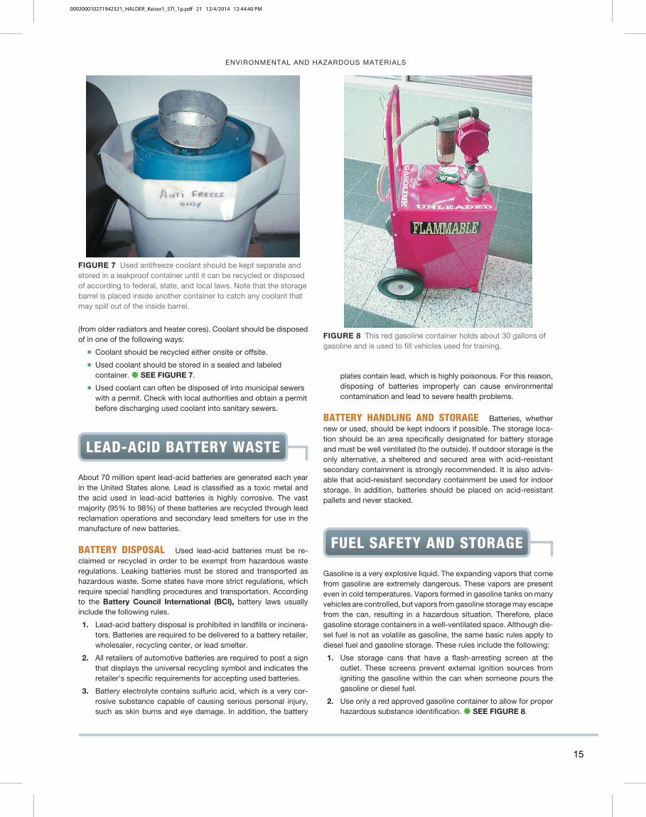
� Used coolant should be stored in a sealed and labeled container. � SEE FIGURE 7 .
� Used coolant can often be disposed of into municipal sewers with a permit. Check with local authorities and obtain a permit before discharging used coolant into sanitary sewers.
plates contain lead, which is highly poisonous. For this reason, disposing of batteries improperly can cause environmental contamination and lead to severe health problems.
BATTERY HANDLING AND STORAGE Batteries, whether new or used, should be kept indoors if possible. The storage loca-tion should be an area specifically designated for battery storage and must be well ventilated (to the outside). If outdoor storage is the only alternative, a sheltered and secured area with acid-resistant secondary containment is strongly recommended. It is also advis-able that acid-resistant secondary containment be used for indoor storage. In addition, batteries should be placed on acid-resistant pallets and never stacked.
FIGURE 7 Used antifreeze coolant should be kept separate and stored in a leakproof container until it can be recycled or disposed of according to federal, state, and local laws. Note that the storage barrel is placed inside another container to catch any coolant that may spill out of the inside barrel.
LEAD-ACID BATTERY WASTE
About 70 million spent lead-acid batteries are generated each year in the United States alone . Lead is classified as a toxic metal and the acid used in lead-acid batteries is highly corrosive. The vast majority (95% to 98%) of these batteries are recycled through lead reclamation operations and secondary lead smelters for use in the manufacture of new batteries.
BATTERY DISPOSAL Used lead-acid batteries must be re-claimed or recycled in order to be exempt from hazardous waste regulations. Leaking batteries must be stored and transported as hazardous waste. Some states have more strict regulations, which require special handling procedures and transportation. According to the Battery Council International (BCI), battery laws usually include the following rules.
1. Lead-acid battery disposal is prohibited in landfills or incinera-tors. Batteries are required to be delivered to a battery retailer, wholesaler, recycling center, or lead smelter.
2. All retailers of automotive batteries are required to post a sign that displays the universal recycling symbol and indicates the retailer’s specific requirements for accepting used batteries.
3. Battery electrolyte contains sulfuric acid, which is a very cor-rosive substance capable of causing serious personal injury, such as skin burns and eye damage. In addition, the battery
FIGURE 8 This red gasoline container holds about 30 gallons of gasoline and is used to fill vehicles used for training.
Gasoline is a very explosive liquid. The expanding vapors that come from gasoline are extremely dangerous. These vapors are present even in cold temperatures. Vapors formed in gasoline tanks on many vehicles are controlled, but vapors from gasoline storage may escape from the can, resulting in a hazardous situation. Therefore, place gasoline storage containers in a well-ventilated space. Although die-sel fuel is not as volatile as gasoline, the same basic rules apply to diesel fuel and gasoline storage. These rules include the following:
1. Use storage cans that have a flash-arresting screen at the outlet. These screens prevent external ignition sources from igniting the gasoline within the can when someone pours the gasoline or diesel fuel.
2. Use only a red approved gasoline container to allow for proper hazardous substance identification. � SEE FIGURE 8 .
FUEL SAFETY AND STORAGE
15
000200010271942321_HALDER_Keiser1_STI_1p.pdf 21 12/4/2014 12:44:40 PM

IGNITION SYSTEM COMPONENTS AND OPERATION
cylinder placed on the valve covers. Short secondary ignition spark plug wires are used to connect the output terminal of the ignition coil to the spark plug, which explains why this system is called a coil-near-plug system.
� A combination of coil-on-plug and waste-spark systems fires a spark plug attached to the coil and uses a spark plug wire attached to the other secondary terminal of the coil to fire another spark plug of the companion cylinder. This type of system is used in some Chrysler Hemi V-8 and Toyota V-6 engines. � SEE FIGURE 18 . Most new engines use coil-over-plug-type ignition systems.
Each coil is controlled by the PCM, which can vary the ignition tim-ing separately for each cylinder based on signals the PCM receives from the knock sensor(s). For example, if the knock sensor detects that a spark knock has occurred after firing cylinder 3, then the PCM will continue to monitor cylinder 3 and retard timing on just this one cylinder if necessary to prevent engine damaging detonation.
ION-SENSING IGNITION In an ion-sensing ignition system, the spark plug itself becomes a sensor. An ion-sensing ignition uses
timing also can be changed (retarded or advanced) on a cylinder-by-cylinder basis for maximum performance and to respond to knock sensor signals.
TYPES OF COP SYSTEMS There are two basic types of coil-on-plug ignition.
� Two primary wires. This design uses the vehicle computer to control the firing of the ignition coil. The two wires include igni-tion voltage feed and the pulse ground wire, which is controlled by the PCM. The ignition control module (ICM) is located in the PCM, which handles all ignition timing and coil on-time control.
� Three primary wires. This design includes an ignition module at each coil. The three wires include: � Ignition voltage
� Ground
� Pulse from the PCM to the built-in ignition module Vehicles use a variety of coil-on-plug-type ignition systems,
such as the following:
� Many General Motors V-8 engines use a coil-near-plug sys-tem with individual coils and modules for each individual
CKPSENSOR
B+
IGNITIONSWITCH
INTEGRALCOIL & PLUG
PCM
FIGURE 16 A typical coil-on-plug ignition system showing the triggering and the switching being performed by the PCM via input from the crankshaft position sensor.
INTAKE CAMPHASER SOLENOID
COIL-ON-PLUG (COP)COILS
EXHAUST CAMPHASERSOLENOID CAMSHAFT
POSITION (CMP)SENSOR
FIGURE 17 An overhead camshaft engine equipped with variable valve timing on both the intake and exhaust camshafts and the coil-on-plug ignition.
COIL
SPARK PLUG WIRETO COMPANIONCYLINDER
FIGURE 18 A Chrysler Hemi V-8 that has two spark plugs per cylinder. The coil on top of one spark plug fires that plug and, through a spark plug wire, fires a plug in the companion cylinder.
SAFETY TIP
Never Disconnect a Spark Plug Wire When the Engine Is Running!
Ignition systems produce a high-voltage pulse necessary to ignite a lean air-fuel mixture. If you disconnect a spark plug wire when the engine is running, this high-voltage spark could cause personal injury or damage to the ignition coil and/or ignition module.
200
000200010271942321_HALDER_Keiser1_STI_1p.pdf 206 12/4/2014 12:45:00 PM
IGNITION SYSTEM COMPONENTS AND OPERATION
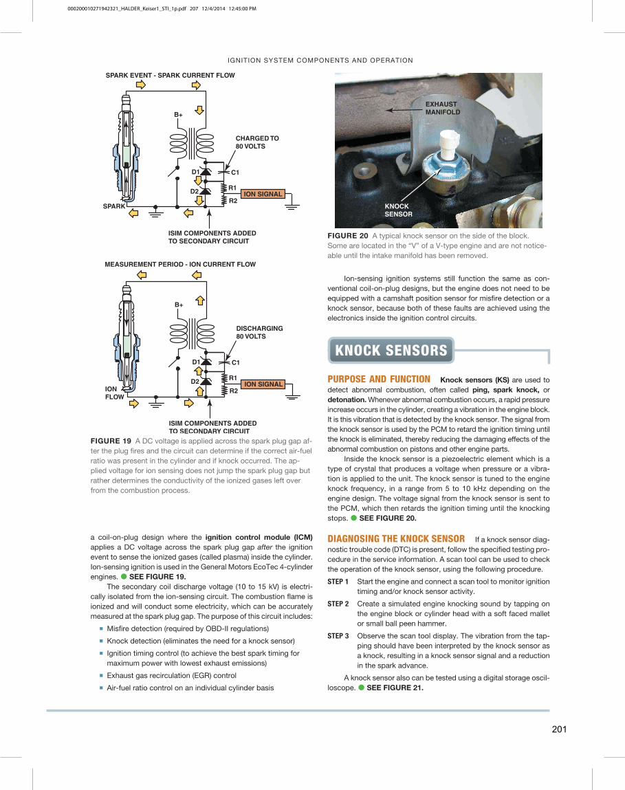
a coil-on-plug design where the ignition control module (ICM) applies a DC voltage across the spark plug gap after the ignition event to sense the ionized gases (called plasma) inside the cylinder. Ion-sensing ignition is used in the General Motors EcoTec 4-cylinder engines. � SEE FIGURE 19 .
The secondary coil discharge voltage (10 to 15 kV) is electri-cally isolated from the ion-sensing circuit. The combustion flame is ionized and will conduct some electricity, which can be accurately measured at the spark plug gap. The purpose of this circuit includes:
� Misfire detection (required by OBD-II regulations)
� Knock detection (eliminates the need for a knock sensor)
� Ignition timing control (to achieve the best spark timing for maximum power with lowest exhaust emissions)
� Exhaust gas recirculation (EGR) control
� Air-fuel ratio control on an individual cylinder basis
B+
D1
D2
C1
R1
R2 SPARK
CHARGED TO 80 VOLTS
SPARK EVENT - SPARK CURRENT FLOW
ISIM COMPONENTS ADDED TO SECONDARY CIRCUIT
ION SIGNAL
B+
D1
D2
C1
R1
R2
DISCHARGING 80 VOLTS
ISIM COMPONENTS ADDED TO SECONDARY CIRCUIT
MEASUREMENT PERIOD - ION CURRENT FLOW
ION FLOW
ION SIGNAL
FIGURE 19 A DC voltage is applied across the spark plug gap af-ter the plug fires and the circuit can determine if the correct air-fuel ratio was present in the cylinder and if knock occurred. The ap-plied voltage for ion sensing does not jump the spark plug gap but rather determines the conductivity of the ionized gases left over from the combustion process.
EXHAUSTMANIFOLD
KNOCKSENSOR
FIGURE 20 A typical knock sensor on the side of the block. Some are located in the “V” of a V-type engine and are not notice-able until the intake manifold has been removed.
PURPOSE AND FUNCTION Knock sensors (KS) are used to detect abnormal combustion, often called ping, spark knock, or detonation. Whenever abnormal combustion occurs, a rapid pressure increase occurs in the cylinder, creating a vibration in the engine block. It is this vibration that is detected by the knock sensor. The signal from the knock sensor is used by the PCM to retard the ignition timing until the knock is eliminated, thereby reducing the damaging effects of the abnormal combustion on pistons and other engine parts.
Inside the knock sensor is a piezoelectric element which is a type of crystal that produces a voltage when pressure or a vibra-tion is applied to the unit. The knock sensor is tuned to the engine knock frequency, in a range from 5 to 10 kHz depending on the engine design. The voltage signal from the knock sensor is sent to the PCM, which then retards the ignition timing until the knocking stops. � SEE FIGURE 20 .
DIAGNOSING THE KNOCK SENSOR If a knock sensor diag-nostic trouble code (DTC) is present, follow the specified testing pro-cedure in the service information. A scan tool can be used to check the operation of the knock sensor, using the following procedure.
STEP 1 Start the engine and connect a scan tool to monitor ignition timing and/or knock sensor activity.
STEP 2 Create a simulated engine knocking sound by tapping on the engine block or cylinder head with a soft faced mallet or small ball peen hammer.
STEP 3 Observe the scan tool display. The vibration from the tap-ping should have been interpreted by the knock sensor as a knock, resulting in a knock sensor signal and a reduction in the spark advance.
A knock sensor also can be tested using a digital storage oscil-loscope. � SEE FIGURE 21 .
KNOCK SENSORS
Ion-sensing ignition systems still function the same as con-ventional coil-on-plug designs, but the engine does not need to be equipped with a camshaft position sensor for misfire detection or a knock sensor, because both of these faults are achieved using the electronics inside the ignition control circuits.
201
000200010271942321_HALDER_Keiser1_STI_1p.pdf 207 12/4/2014 12:45:00 PM
VEHICLE EMISSION STANDARDS AND TESTING
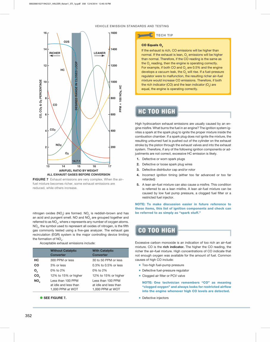
nitrogen oxides (NO 2 ) are formed. NO 2 is reddish-brown and has an acid and pungent smell. NO and NO 2 are grouped together and referred to as NO X , where x represents any number of oxygen atoms. NO X , the symbol used to represent all oxides of nitrogen, is the fifth gas commonly tested using a five-gas analyzer. The exhaust gas recirculation (EGR) system is the major controlling device limiting the formation of NO X .
Acceptable exhaust emissions include:
Without Catalytic Converter
With Catalytic Converter
HC 300 PPM or less 30 to 50 PPM or less
CO 3% or less 0.3% to 0.5% or less
O 2 0% to 2% 0% to 2%
CO 2 12% to 15% or higher 12% to 15% or higher
NO X Less than 100 PPM at idle and less than 1,000 PPM at WOT
Less than 100 PPM at idle and less than 1,000 PPM at WOT
� SEE FIGURE 7 .
13 161514 17
14
12
10
8
6
4
16
2
1400
1200
1000
800
600
400
200
1600
CO
, CO
2 &
O2
PE
RC
EN
TAG
E
PP
M �
100
NO
X, H
C
AIR/FUEL RATIO BY WEIGHTALL EXHAUST GASES BEFORE CONVERSION
CO2
O2
NOX
CO
14.7:1
HC
RICHER
O2S
LEANER
DE
SIR
ED
RA
NG
E IN
CL
OS
ED
LO
OP
FIGURE 7 Exhaust emissions are very complex. When the air–fuel mixture becomes richer, some exhaust emissions are reduced, while others increase.
High hydrocarbon exhaust emissions are usually caused by an en-gine misfire. What burns the fuel in an engine? The ignition system ig-nites a spark at the spark plug to ignite the proper mixture inside the combustion chamber. If a spark plug does not ignite the mixture, the resulting unburned fuel is pushed out of the cylinder on the exhaust stroke by the piston through the exhaust valves and into the exhaust system. Therefore, if any of the following ignition components or ad-justments are not correct, excessive HC emission is likely.
1. Defective or worn spark plugs
2. Defective or loose spark plug wires
3. Defective distributor cap and/or rotor
4. Incorrect ignition timing (either too far advanced or too far retarded)
5. A lean air–fuel mixture can also cause a misfire. This condition is referred to as a lean misfire. A lean air-fuel mixture can be caused by low fuel pump pressure, a clogged fuel filter or a restricted fuel injector.
NOTE: To make discussion easier in future reference to these items, this list of ignition components and check can be referred to as simply as “spark stuff.”
HC TOO HIGH
Excessive carbon monoxide is an indication of too rich an air–fuel mixture. CO is the rich indicator. The higher the CO reading, the richer the air–fuel mixture. High concentrations of CO indicate that not enough oxygen was available for the amount of fuel. Common causes of high CO include:
� Too-high fuel-pump pressure
� Defective fuel-pressure regulator
� Clogged air filter or PCV valve
NOTE: One technician remembers “CO” as meaning “clogged oxygen” and always looks for restricted airflow into the engine whenever high CO levels are detected.
� Defective injectors
CO TOO HIGH
CO Equals O 2
If the exhaust is rich, CO emissions will be higher than normal. If the exhaust is lean, O 2 emissions will be higher than normal. Therefore, if the CO reading is the same as the O 2 reading, then the engine is operating correctly. For example, if both CO and O 2 are 0.5% and the engine develops a vacuum leak, the O 2 will rise. If a fuel-pressure regulator were to malfunction, the resulting richer air–fuel mixture would increase CO emissions. Therefore, if both the rich indicator (CO) and the lean indicator (O 2 ) are equal, the engine is operating correctly.
TECH TIP
352
000200010271942321_HALDER_Keiser1_STI_1p.pdf 358 12/4/2014 12:45:10 PM

VEHICLE EMISSION STANDARDS AND TESTING
LOW PRESSURE AREASBEHIND EXHAUST PULSES
“SLUGS” OF EXHAUST
OUTSIDE AIR IS DRAWNINTO HOLE
EXHAUSTLEAKS OUTHOLE
HOLE INEXHAUST
EXHAUST PIPE
FIGURE 8 A hole in the exhaust system can cause outside air (containing oxygen) to be drawn into the exhaust system. This ex-tra oxygen can be confusing to a service technician because the extra O 2 in the exhaust stream could be misinterpreted as a too-lean air–fuel mixture.
How to Find a Leak in the Exhaust System
A hole in the exhaust system can dilute the exhaust gases with additional oxygen (O 2 ). � SEE FIGURE 8 .
This additional O 2 in the exhaust can lead the service technician to believe that the air–fuel mixture is too lean. To help identify an exhaust leak, perform an exhaust analysis at idle and at 2500 RPM (fast idle) and compare with the following:
• If the O 2 is high at idle and at 2500 RPM, the mixture is lean at both idle and at 2500 RPM.
• If the O 2 is low at idle and high at 2500 RPM, this usu-ally means that the vehicle is equipped with a working AIR pump.
• If the O 2 is high at idle, but okay at 2500 RPM, a hole in the exhaust or a small vacuum leak that is “covered up” at higher speed is indicated.
TECH TIP
Your Nose Knows
Using the nose, a technician can often identify a major problem without having to connect the vehicle to an exhaust analyzer. For example,
• The strong smell of exhaust is due to excessive un-burned hydrocarbon (HC) emissions. Look for an igni-tion system fault that could prevent the proper burning of the fuel. A vacuum leak could also cause a lean mis-fire and cause excessive HC exhaust emissions.
• If your eyes start to burn or water, suspect excessive oxides of nitrogen (NO X ) emissions. The oxides of ni-trogen combine with the moisture in the eyes to form a mild solution of nitric acid. The acid formation causes the eyes to burn and water. Excessive NO X exhaust emissions can be caused by: • A vacuum leak causing higher-than-normal combus-
tion chamber temperatures • Overadvanced ignition timing causing higher-than-
normal combustion chamber temperatures • Lack of proper amount of exhaust gas recirculation
(EGR) (This is usually noticed above idle on most vehicles.)
• Dizzy feeling or headache. This is commonly caused by excessive carbon monoxide (CO) exhaust emis-sions. Get into fresh air as soon as possible. A prob-able cause of high levels of CO is an excessively rich air–fuel mixture.
TECH TIP
Two gas exhaust analyzers (HC and CO) work well, but both HC and CO are consumed (converted) inside the catalytic converter. The amount of leftover oxygen coming out of the tailpipe is an indication of leanness. The higher the O 2 level, the leaner the exhaust. Oxygen therefore is the lean indicator. Acceptable levels of O 2 are 0% to 2%.
NOTE: A hole in the exhaust system can draw outside air (oxygen) into the exhaust system. Therefore, to be assured of an accurate reading, carefully check the exhaust system for leaks. Using a smoke machine is an easy method to locate leaks in the exhaust system.
Carbon dioxide (CO 2 ) is a measure of efficiency. The higher the level of CO 2 in the exhaust stream, the more efficiently the engine is operating. Levels of 12% to 15% are considered to be acceptable.
MEASURING OXYGEN (O 2 )
AND CARBON DIOXIDE (CO 2 )
Because CO 2 levels peak at an air–fuel mixture of 14.7:1, a lower level of CO 2 indicates either a too-rich or a too-lean condition. The CO 2 measurement by itself does not indicate which condition is present. For example:
CO 2 � 8% (This means efficiency is low and the air–fuel mixture is not correct.)
Look at O 2 and CO levels.
A high O 2 indicates lean and a high CO indicates rich.
Oxides of nitrogen are formed by high temperature—over 2500°F (1370°C)—and/or pressures inside the combustion chamber. Oxides of nitrogen contribute to the formation of photochemical smog when sunlight reacts chemically with NO X and unburned hydrocar-bons (HC). Smog is a term derived by combining the words smoke and fog . Ground-level ozone is a constituent of smog. Ozone is an enriched oxygen molecule with three atoms of oxygen (O 3 ) instead of the normal two atoms of oxygen (O 2 ).
Ozone in the upper atmosphere is beneficial because it blocks out harmful ultraviolet rays that contribute to skin cancer. However, at ground level, this ozone (smog) is an irritant to the respiratory system.
PHOTOCHEMICAL
SMOG FORMATION
353
000200010271942321_HALDER_Keiser1_STI_1p.pdf 359 12/4/2014 12:45:10 PM