table of contents - starte… · programming/debugging with arm-jtag ... msp430 also, so there is...
TRANSCRIPT

1
GETTING STARTED WITH ARM SAM7S64 Part 1
Keywords: Get started, Microcontroller, ARM, SAM7S64, ARM-JTAG, IAR EWARM
TechToys www.TechToys.com.hk
All rights reserved By John Leung, updated 19 July 06
Table of Contents
Page Table of Contents 1 1. Introduction 2 2. Hardware Requirement 3 3. Software Requirement 3 4. Prepare the IDE
4.1 Installation of EWARM 4.2 Installation of SAM Boot Assistant (SAM-BA) 4.3 Installation of ARM-Jtag and H-JTAG driver
4
5. The first project (Let’s blink the LEDs!) 11
Appendix A : When ARM JTAG failed with my Windows 2000 workstation 29 Appendix B : Why my first project didn’t RESET? 30

2
GETTING STARTED WITH ARM SAM7S64 Part 1
Keywords: Get started, Microcontroller, ARM, SAM7S64, ARM-JTAG, IAR EWARM
TechToys www.TechToys.com.hk
All rights reserved By John Leung, updated 19 July 06
1. Introduction Olimex AT91SAM7-P64-A development board provides a low cost alternative to evaluation of the Atmel’s AT91SAM7S low pin-count 32-bit ARM RISC processor. Features of the AT91SAM7-P64-A development board as below.
• MCU: AT91SAM7S64 16/32 bit ARM7TDMI™ with 64K Bytes Program Flash, 16K Bytes RAM, USB 2.0, RTT, 10 bit ADC, 2x UARTs, TWI (I2C), SPI, 3x 32bit TIMERS, 4x PWM, SSC (I2S), WDT, PDC (DMA) for all peripherals, up to 55MHz operation
• standard JTAG connector with ARM 2x10 pin layout for programming/debugging with ARM-JTAG
• USB connector
• Two channel RS232 interface and driver
• SD/MMC card connector
• two push-buttons
• trimpot connected to ADC
• thermistor connected to ADC
• two status LEDs
• single power supply: 6V – 9V DC/AC required
• 18.432 MHz crystal • Full Schematics available
3
GETTING STARTED WITH ARM SAM7S64 Part 1
Keywords: Get started, Microcontroller, ARM, SAM7S64, ARM-JTAG, IAR EWARM
TechToys www.TechToys.com.hk
All rights reserved By John Leung, updated 19 July 06
2. Hardware Requirement Besides the AT91SAM7-P64 board, we need few additional hardware to get started:
1. A PC running Windows XP 2. Olimex ARM JTAG debugger 3. USB Cable (Type A <-> Type B) 4. Straight parallel port extender cable (optional) 5. 6V – 9V DC transformer
3. Software Requirement 1. Free 32KB Kickstart edition of IAR Embedded Workbench Kiskstart for
ARM” V4.30A (EWARM) downloaded from www.iar.se 2. H-JTAG Server downloaded from www.olimex.com or
www.TechToys.com.hk under “Tools and Software->ARM JTAG” section. The latest version is v0.3.1.
3. An example program downloaded from www.TechToys.com.hk under “ARM Boards->Atmel SAM7-P64->Documents->Getting Started with SAM7 (30 pages Guide) & source code”.
4. SAM Boot Assistant (SAM-BA) obtained from www.at91.com

4
GETTING STARTED WITH ARM SAM7S64 Part 1
Keywords: Get started, Microcontroller, ARM, SAM7S64, ARM-JTAG, IAR EWARM
TechToys www.TechToys.com.hk
All rights reserved By John Leung, updated 19 July 06
4. Prepare the IDE 4.1 Installation of EWARM The first thing to do is to download a copy of the “IAR Embedded Workbench Kiskstart for ARM” V4.30A (EWARM) from http://supp.iar.com/Download/SW/?item=EWARM-KS32 and get it installed. After download, double click on the installation file (93MB). Complete the registration afterwards.
From Windows Start menu, there will be a program as IAR Embedded Workbench. My PC have IAR Embedded Workbench KickStart for MSP430 also, so there is another ‘IAR Embedded…MSP430’ above the ARM KickStart. This MSP430 workbench is not relevant to ARM development.

5
GETTING STARTED WITH ARM SAM7S64 Part 1
Keywords: Get started, Microcontroller, ARM, SAM7S64, ARM-JTAG, IAR EWARM
TechToys www.TechToys.com.hk
All rights reserved By John Leung, updated 19 July 06
4.2 Installation of SAM Boot Assistant (SAM-BA) SAM-BA is a software provided by Atmel to in-circuit program AT91 devices via RS232 or USB. NO PROGRAMMER IS REQUIRED! From www.at91.com, download SAM-BA and get it installed. There is not much difficulty with it. Restart the PC after installation.
When SAM-BA starts, there is a dialog box asking for connection protocol as below. Our board is AT91SAM7S64-EK compatible. Select AT91SAM7S64-EK. We may use either serial connection or USB connection. Let’s use USB connection because the board will be powered by the USB, no need to use external power for the SAM board in this case. Click on USB connection button. I did that, and I have got an error message as below!
6
GETTING STARTED WITH ARM SAM7S64 Part 1
Keywords: Get started, Microcontroller, ARM, SAM7S64, ARM-JTAG, IAR EWARM
TechToys www.TechToys.com.hk
All rights reserved By John Leung, updated 19 July 06
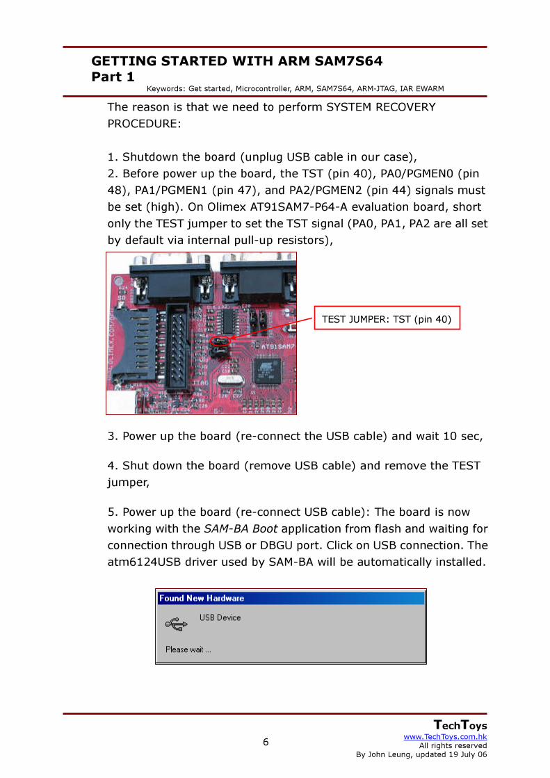
The reason is that we need to perform SYSTEM RECOVERY PROCEDURE:
1. Shutdown the board (unplug USB cable in our case), 2. Before power up the board, the TST (pin 40), PA0/PGMEN0 (pin 48), PA1/PGMEN1 (pin 47), and PA2/PGMEN2 (pin 44) signals must be set (high). On Olimex AT91SAM7-P64-A evaluation board, short only the TEST jumper to set the TST signal (PA0, PA1, PA2 are all set by default via internal pull-up resistors),
3. Power up the board (re-connect the USB cable) and wait 10 sec,
4. Shut down the board (remove USB cable) and remove the TEST jumper,
5. Power up the board (re-connect USB cable): The board is now working with the SAM-BA Boot application from flash and waiting for connection through USB or DBGU port. Click on USB connection. The atm6124USB driver used by SAM-BA will be automatically installed.
TEST JUMPER: TST (pin 40)

7
GETTING STARTED WITH ARM SAM7S64 Part 1
Keywords: Get started, Microcontroller, ARM, SAM7S64, ARM-JTAG, IAR EWARM
TechToys www.TechToys.com.hk
All rights reserved By John Leung, updated 19 July 06
SAM-BA will start. From here, we may download any executable file to our SAM7 ARM mcu (browse to *.bin file -> Send file -> press RESET button onboard). Visit our web page to find a simple LED blink binary file in *.bin format to simply blink the GREEN and YELLOW LEDs. Else, you may also visit www.at91.com for an executable version of Mass Storage application for SAM7S64. Indeed, I was able to turn my SAM board to a USB thumb drive, though it was only a miserable 39KB FAT-format drive because it used the internal flash of the SAM7S64 for storage. Nevertheless, we may request the full source code from Atmel to learn implementation of a FAT file system in SAM. Because there is a mmc socket onboard exclusive with our SAM board, it will be possible for us to extend the file system to mmc cards and use the SAM board for any data logging project.
8
GETTING STARTED WITH ARM SAM7S64 Part 1
Keywords: Get started, Microcontroller, ARM, SAM7S64, ARM-JTAG, IAR EWARM
TechToys www.TechToys.com.hk
All rights reserved By John Leung, updated 19 July 06
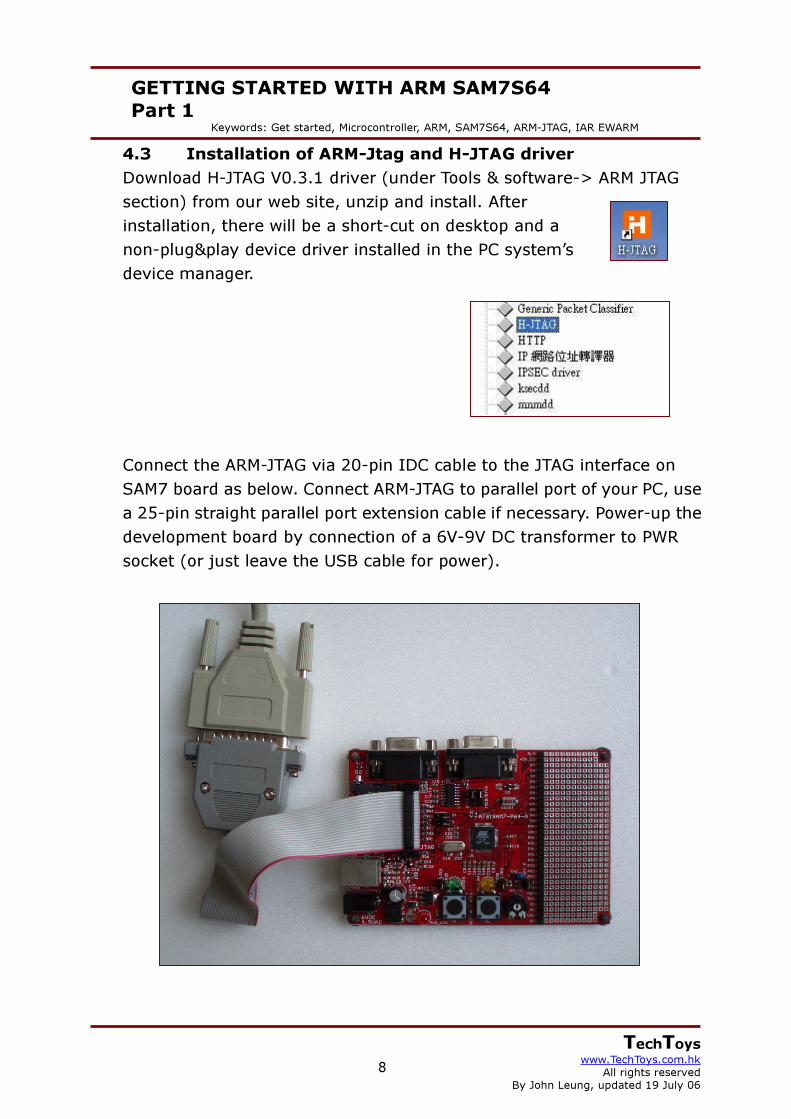
4.3 Installation of ARM-Jtag and H-JTAG driver Download H-JTAG V0.3.1 driver (under Tools & software-> ARM JTAG section) from our web site, unzip and install. After installation, there will be a short-cut on desktop and a non-plug&play device driver installed in the PC system’s device manager.
Connect the ARM-JTAG via 20-pin IDC cable to the JTAG interface on SAM7 board as below. Connect ARM-JTAG to parallel port of your PC, use a 25-pin straight parallel port extension cable if necessary. Power-up the development board by connection of a 6V-9V DC transformer to PWR socket (or just leave the USB cable for power).
9
GETTING STARTED WITH ARM SAM7S64 Part 1
Keywords: Get started, Microcontroller, ARM, SAM7S64, ARM-JTAG, IAR EWARM
TechToys www.TechToys.com.hk
All rights reserved By John Leung, updated 19 July 06
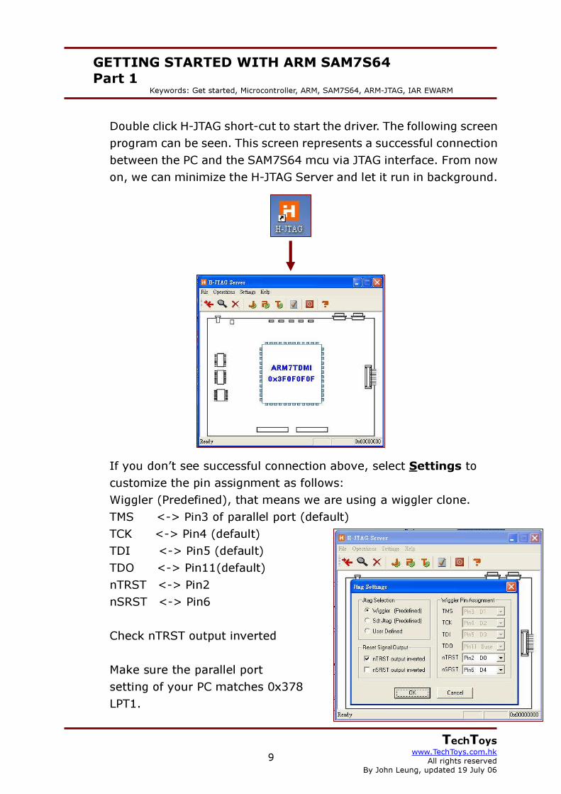
Double click H-JTAG short-cut to start the driver. The following screen program can be seen. This screen represents a successful connection between the PC and the SAM7S64 mcu via JTAG interface. From now on, we can minimize the H-JTAG Server and let it run in background.
If you don’t see successful connection above, select Settings to customize the pin assignment as follows: Wiggler (Predefined), that means we are using a wiggler clone. TMS <-> Pin3 of parallel port (default) TCK <-> Pin4 (default) TDI <-> Pin5 (default) TDO <-> Pin11(default) nTRST <-> Pin2 nSRST <-> Pin6 Check nTRST output inverted
Make sure the parallel port
setting of your PC matches 0x378 LPT1.

10
GETTING STARTED WITH ARM SAM7S64 Part 1
Keywords: Get started, Microcontroller, ARM, SAM7S64, ARM-JTAG, IAR EWARM
TechToys www.TechToys.com.hk
All rights reserved By John Leung, updated 19 July 06
Click on the magnifying glass icon to reconnect to target (SAM7S64 mcu). If you still cannot succeed in connection, please refer to Appendix A for remarks.
After the H-JTAG Server has made a successful connection with the target board, there will be an H-SERVER icon at the lower left corner of the desktop. This icon will change to a “PLAY” icon during debug.
Magnifying glass to reconnect

11
GETTING STARTED WITH ARM SAM7S64 Part 1
Keywords: Get started, Microcontroller, ARM, SAM7S64, ARM-JTAG, IAR EWARM
TechToys www.TechToys.com.hk
All rights reserved By John Leung, updated 19 July 06
5. The first project (Let’s blink the LEDs!) Download an application from us at www.TechToys.com.hk and unzip the program to a convenient place. It is under ARM Boards -> Atmel SAM7-P64 -> Documents -> Getting Started with SAM7 (30 pages Guide) & source code. Place the project folder anywhere you like. In my case, I have placed it under D:\SAM7S64. Launch EWARM from Windows Start Menu, browse to D:\SAM7S64\AT91SAM7S-BasicTools\Compil\basic.eww
Click Open.

12
GETTING STARTED WITH ARM SAM7S64 Part 1
Keywords: Get started, Microcontroller, ARM, SAM7S64, ARM-JTAG, IAR EWARM
TechToys www.TechToys.com.hk
All rights reserved By John Leung, updated 19 July 06
You will see the workspace opened. The left panel is the workspace panel. Make sure the drop-down menu have RAM_Debug selected.
This project is not much different from an example available under the installation directory of EWARM. I just modified the board.h file to suit our SAM board. Besides, I have also modified some of the functions provided by the standard library to see how the program run. Example is : // AT91F_PMC_EnablePeriphClock ( AT91C_BASE_PMC, 1 << AT91C_ID_PIOA ) ; *AT91C_PMC_SCER = AT91C_CKGR_MOSCEN; // main oscillator enable *AT91C_PMC_PCER = 1<<AT91C_ID_PIOA; // peripheral clock enable Please see comment in main.c and board.h for modifications made.

13
GETTING STARTED WITH ARM SAM7S64 Part 1
Keywords: Get started, Microcontroller, ARM, SAM7S64, ARM-JTAG, IAR EWARM
TechToys www.TechToys.com.hk
All rights reserved By John Leung, updated 19 July 06
Let’s debug our application as follows: Under Project->Options, select category Debugger. There are several options built-in the EWARM. H-JTAG Server is RDI compatible, so we select RDI as the C-SPY Driver. Check Run to check-box, and put in main in the text box. This means we jump to the c-function main () in main.c when debug. If this option is not checked, we will jump to the first line of code of Cstartup.s79 when debug. Click on another instance of RDI underneath Debugger. Browse to the H-JTAG RDI driver (H-JTAG.dll) from the H-JTAG installation directory. Normally, it would be under C:\Program Files\H-JTAG V0.2\H-JTAG.dll. Finally press OK to save all settings.

14
GETTING STARTED WITH ARM SAM7S64 Part 1
Keywords: Get started, Microcontroller, ARM, SAM7S64, ARM-JTAG, IAR EWARM
TechToys www.TechToys.com.hk
All rights reserved By John Leung, updated 19 July 06
Just to make sure we have all code complied and linked, we may right click on the Basic – RAM_Debug workspace and select Rebuild All. Build results show no error and warning.

15
GETTING STARTED WITH ARM SAM7S64 Part 1
Keywords: Get started, Microcontroller, ARM, SAM7S64, ARM-JTAG, IAR EWARM
TechToys www.TechToys.com.hk
All rights reserved By John Leung, updated 19 July 06
Expand each of the categories under the workspace. We can see all output files and their dependency. Object files = *.r79 Linker command files = *.xcl Macro files for debugger = *.mac Output file for RAM-Debug = *.d79

16
GETTING STARTED WITH ARM SAM7S64 Part 1
Keywords: Get started, Microcontroller, ARM, SAM7S64, ARM-JTAG, IAR EWARM
TechToys www.TechToys.com.hk
All rights reserved By John Leung, updated 19 July 06
It is possible for us to customerize what file to output under the C complier option. Right click on the project workspace, Basic-RAM_Debug -> Options Select C/C++ Complier under Category, select List tab. Check Output list file option. Rebuild All.
17
GETTING STARTED WITH ARM SAM7S64 Part 1
Keywords: Get started, Microcontroller, ARM, SAM7S64, ARM-JTAG, IAR EWARM
TechToys www.TechToys.com.hk
All rights reserved By John Leung, updated 19 July 06
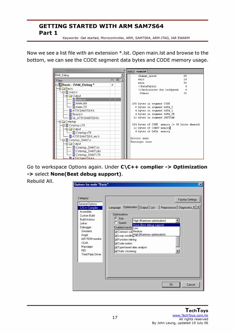
Now we see a list file with an extension *.lst. Open main.lst and browse to the bottom, we can see the CODE segment data bytes and CODE memory usage.
Go to workspace Options again. Under C\C++ complier -> Optimization -> select None(Best debug support). Rebuild All.

18
GETTING STARTED WITH ARM SAM7S64 Part 1
Keywords: Get started, Microcontroller, ARM, SAM7S64, ARM-JTAG, IAR EWARM
TechToys www.TechToys.com.hk
All rights reserved By John Leung, updated 19 July 06
Compare the build results with maximum optimization & No optimization, we can see the difference in both CODE and memory usage!
19
GETTING STARTED WITH ARM SAM7S64 Part 1
Keywords: Get started, Microcontroller, ARM, SAM7S64, ARM-JTAG, IAR EWARM
TechToys www.TechToys.com.hk
All rights reserved By John Leung, updated 19 July 06
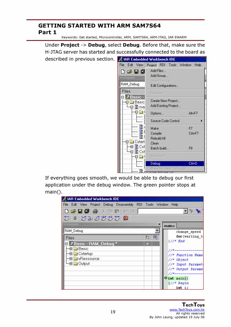
Under Project -> Debug, select Debug. Before that, make sure the H-JTAG server has started and successfully connected to the board as described in previous section. If everything goes smooth, we would be able to debug our first application under the debug window. The green pointer stops at main().

20
GETTING STARTED WITH ARM SAM7S64 Part 1
Keywords: Get started, Microcontroller, ARM, SAM7S64, ARM-JTAG, IAR EWARM
TechToys www.TechToys.com.hk
All rights reserved By John Leung, updated 19 July 06
The following short-keys allow us to perform stepping. Go F5 Step Over F10 Step Into F11 Step Out Shift+F11
Click on View menu->Register. One more time, click on View menu->Disassembly. Now we see the source file main.c, Register map, and the Disassembly listing on the same Window.

21
GETTING STARTED WITH ARM SAM7S64 Part 1
Keywords: Get started, Microcontroller, ARM, SAM7S64, ARM-JTAG, IAR EWARM
TechToys www.TechToys.com.hk
All rights reserved By John Leung, updated 19 July 06
Click on View menu->Memory.
Comparing the memory contents between the Memory map and Disassembly listing, I have got much insight of what the program was all about. Each instruct after compilation has been assigned to an address in the memory space. For example, our first c syntax *AT91C_PMC_SCER = AT91C_CKGR_MOSCEN; has been complied to three assembly syntax 0x0000026E 4814 LDR R0,[PC,#0x050] 0x00000270 2101 MOV R1,#1 0x00000272 6001 STR R1,[R0,#0] From the memory map, we see the machine code 4814, 2101, 6001 at the addresses 0x026E, 0x0270, and 0x0272 respectively.
22
GETTING STARTED WITH ARM SAM7S64 Part 1
Keywords: Get started, Microcontroller, ARM, SAM7S64, ARM-JTAG, IAR EWARM
TechToys www.TechToys.com.hk
All rights reserved By John Leung, updated 19 July 06
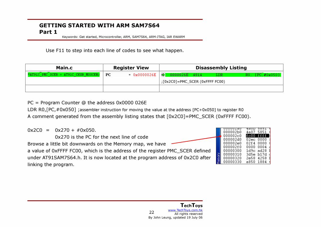
Use F11 to step into each line of codes to see what happen.
PC = Program Counter @ the address 0x0000 026E LDR R0,[PC,#0x050] ;assembler instruction for moving the value at the address [PC+0x050] to register R0 A comment generated from the assembly listing states that [0x2C0]=PMC_SCER (0xFFFF FC00). 0x2C0 = 0x270 + #0x050.
0x270 is the PC for the next line of code Browse a little bit downwards on the Memory map, we have a value of 0xFFFF FC00, which is the address of the register PMC_SCER defined under AT91SAM7S64.h. It is now located at the program address of 0x2C0 after linking the program.
Main.c Register View Disassembly Listing
;[0x2C0]=PMC_SCER (0xFFFF FC00)

23
GETTING STARTED WITH ARM SAM7S64 Part 1
Keywords: Get started, Microcontroller, ARM, SAM7S64, ARM-JTAG, IAR EWARM
TechToys www.TechToys.com.hk
All rights reserved By John Leung, updated 19 July 06
Press F11 to single step. R0 and R1 registers assigned the value of 0xFFFF FC00 and 0x0000 0001, respectively.
By single stepping 3 times, we ran the following code:
Main.c Register View Disassembly Listing
Load the value 0xFFFF FC00, which is the address of the PMC
register PMC_SCER (system clock enable register) located at the
program address 0x2C0, to the working register R0 of the CPU.
Load the value 0x0000 0001 (AT91C_CKGR_MOSCEN) to R1
Load the value holded in R1 to the address holded at [R0+0], that is
0xFFFF FC00 in this case. The result is writing a value of 0x0000 0001
to the address 0xFFFF FC00 (PMC_SCER).

24
GETTING STARTED WITH ARM SAM7S64 Part 1
Keywords: Get started, Microcontroller, ARM, SAM7S64, ARM-JTAG, IAR EWARM
TechToys www.TechToys.com.hk
All rights reserved By John Leung, updated 19 July 06
In conclusion, the result of the first c-code *AT91C_PMC_SCER = AT91C_CKGR_MOSCEN; is to write 0x0000 0001 to the PMC_SCER register, thus enabling the Processor clock by setting PCK=1. Reading the manual of SAM7S64, I have learned more about PMC_SCER. A screen shot of page 189 as shown on right. Continue stepping the codes until *AT91C_PMC_PCER = 1<<AT91C_ID_PIOA; finished. Take a look at the Memory map down to the address 0xFFFF FFC0, we see the value of 0xFFFF FC08 (System Clock Status Register, PMC_SCSR) hold a value of 0x0000 0001, and 0xFFFF FC18 (Peripheral Clock Status Register, PMC_PCSR) hold a value of 0x0000 0004. It seems that because PMC_SCER and PMC_PCER are write-only registers, we cannot get viewed of the value directly from the Memory map. Instead, we need to rely on the PMC_SCSR and PMC_PCSR registers. Please correct me if I am wrong.

25
GETTING STARTED WITH ARM SAM7S64 Part 1
Keywords: Get started, Microcontroller, ARM, SAM7S64, ARM-JTAG, IAR EWARM
TechToys www.TechToys.com.hk
All rights reserved By John Leung, updated 19 July 06
Finally, press (Go) to run the program. Green and yellow LEDs blink. Press B1 to increase the rate, B2 to decrease rate.
Press (Break) to stop running, and step over the main loop by repeating F10 to watch LED blink.
26
GETTING STARTED WITH ARM SAM7S64 Part 1
Keywords: Get started, Microcontroller, ARM, SAM7S64, ARM-JTAG, IAR EWARM
TechToys www.TechToys.com.hk
All rights reserved By John Leung, updated 19 July 06
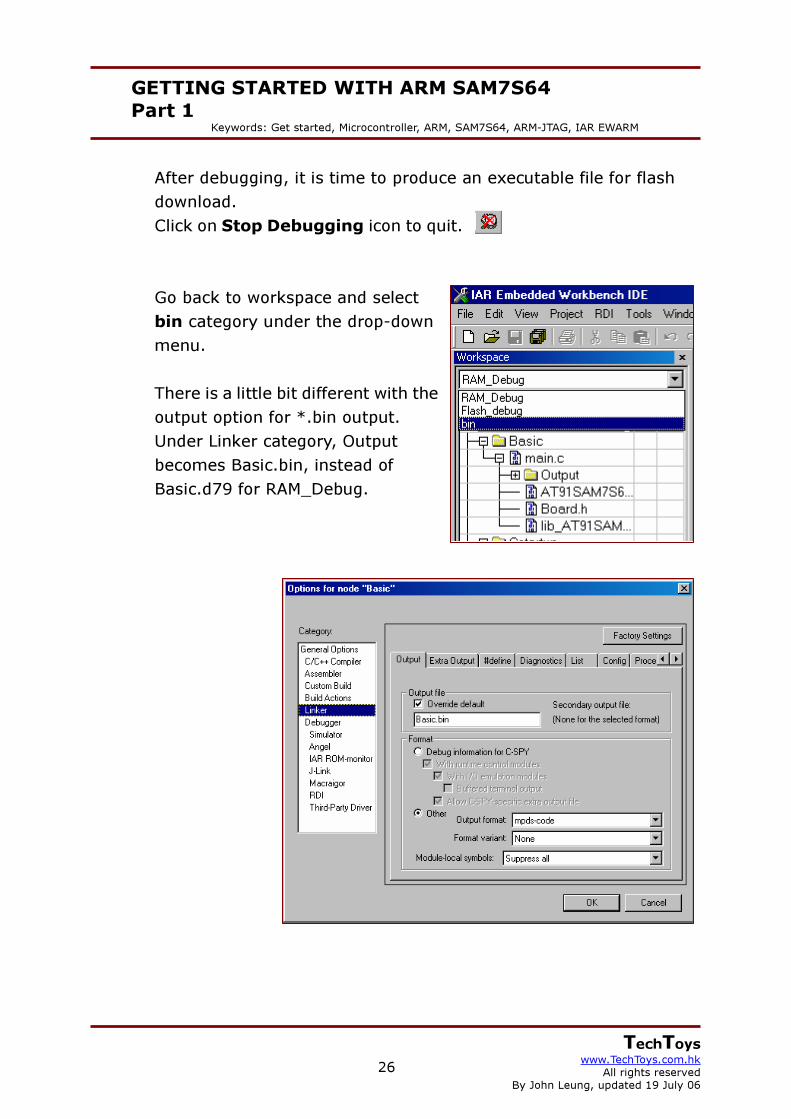
After debugging, it is time to produce an executable file for flash download. Click on Stop Debugging icon to quit. Go back to workspace and select bin category under the drop-down menu. There is a little bit different with the output option for *.bin output. Under Linker category, Output becomes Basic.bin, instead of Basic.d79 for RAM_Debug.
27
GETTING STARTED WITH ARM SAM7S64 Part 1
Keywords: Get started, Microcontroller, ARM, SAM7S64, ARM-JTAG, IAR EWARM
TechToys www.TechToys.com.hk
All rights reserved By John Leung, updated 19 July 06
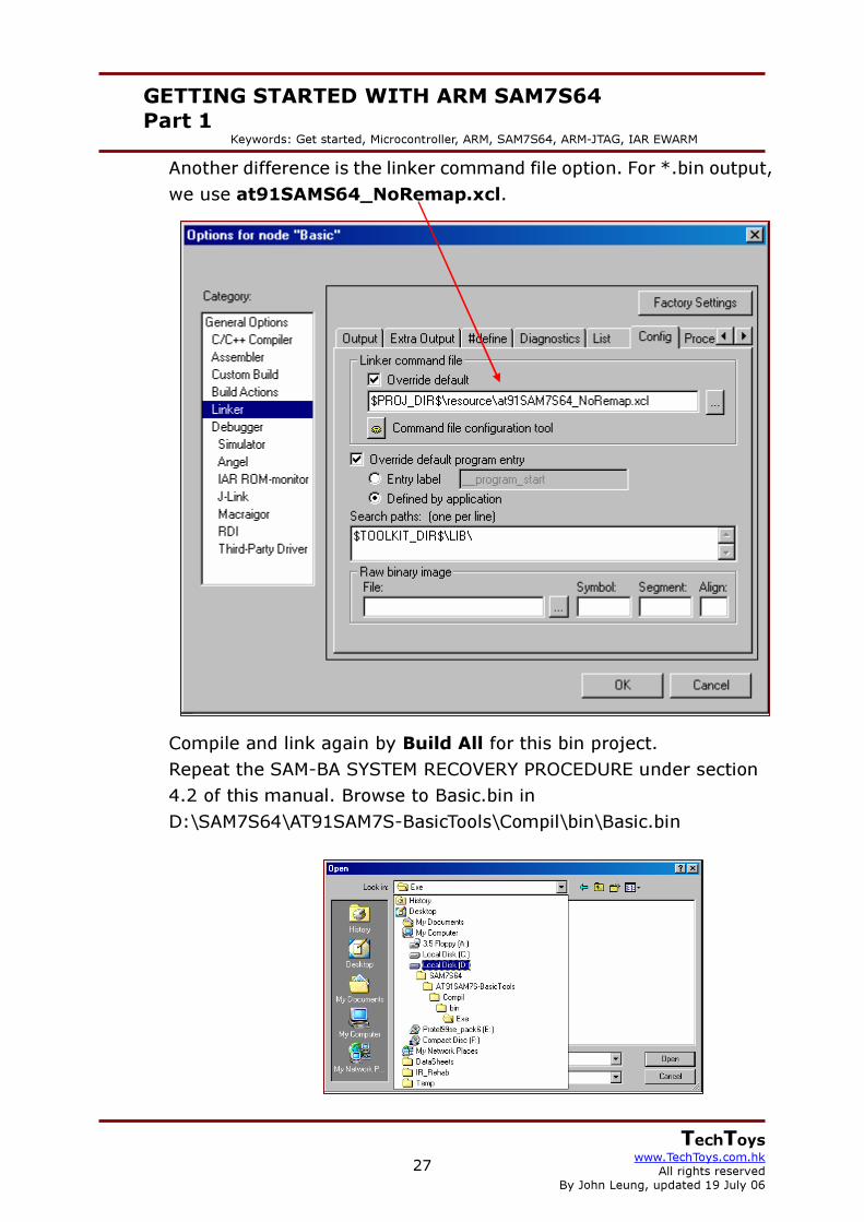
Another difference is the linker command file option. For *.bin output, we use at91SAMS64_NoRemap.xcl. Compile and link again by Build All for this bin project. Repeat the SAM-BA SYSTEM RECOVERY PROCEDURE under section 4.2 of this manual. Browse to Basic.bin in D:\SAM7S64\AT91SAM7S-BasicTools\Compil\bin\Basic.bin
28
GETTING STARTED WITH ARM SAM7S64 Part 1
Keywords: Get started, Microcontroller, ARM, SAM7S64, ARM-JTAG, IAR EWARM
TechToys www.TechToys.com.hk
All rights reserved By John Leung, updated 19 July 06
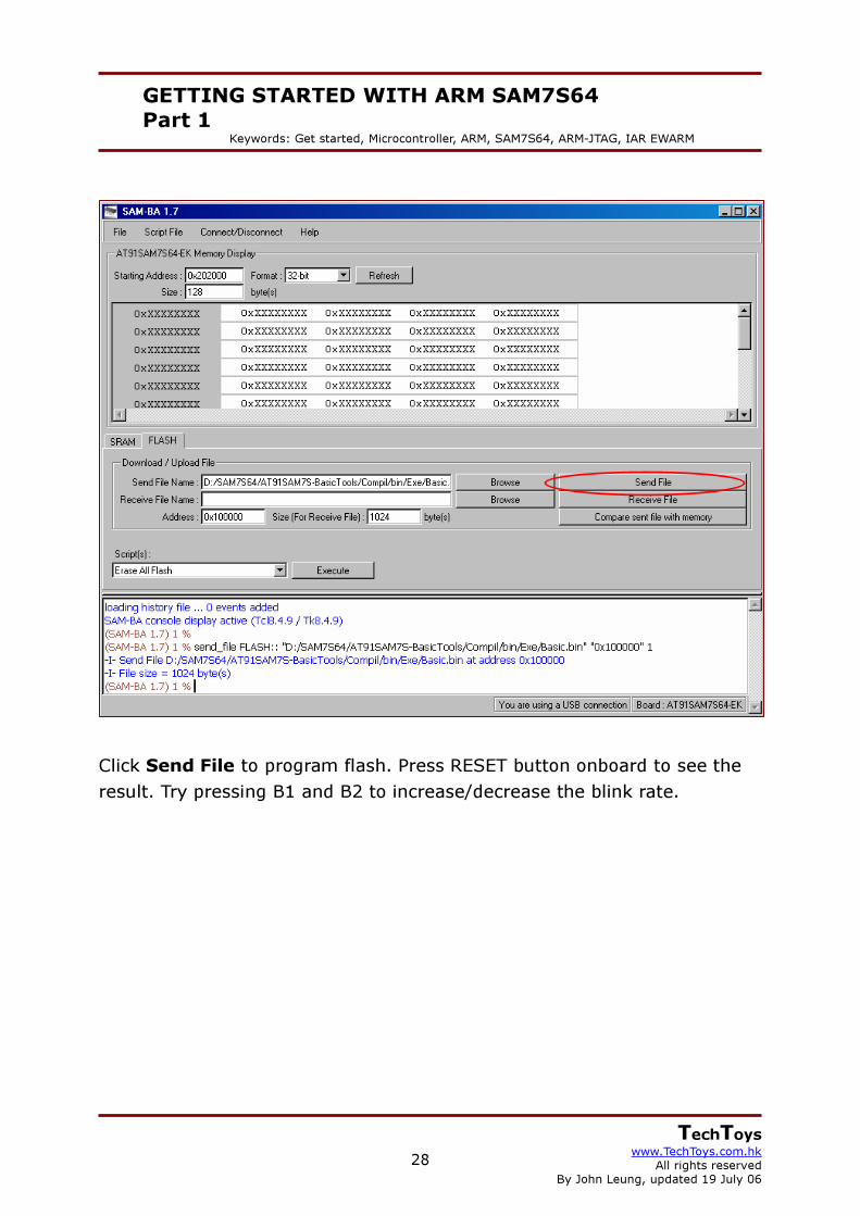
Click Send File to program flash. Press RESET button onboard to see the result. Try pressing B1 and B2 to increase/decrease the blink rate.

29
GETTING STARTED WITH ARM SAM7S64 Part 1
Keywords: Get started, Microcontroller, ARM, SAM7S64, ARM-JTAG, IAR EWARM
TechToys www.TechToys.com.hk
All rights reserved By John Leung, updated 19 July 06
Appendix A : When ARM JTAG failed with my Windows 2000 workstation To be honest, I didn’t debug my first application that smooth as stated in this document. There are several PCs in the office. Some of them are Windows XP Chinese, while my main workstation for programming is a PIII 500 running Windows 2000 SP4. When I used a Windows 2000 workstation, I just couldn’t connect the ARM-JTAG with the SAM board. The following H-JTAG Server message came out no matter how I changed the Settings. Finally, I just dig out an old SDT JTAG and a DIY JTAG that I have made some months ago. By using the same H-JTAG software driver, both of them worked; though I needed to change Settings to sdt Jtag for the yellow one as shown below. For the DIY JTAG, I just use the same settings as Olimex JTAG. Remarks: I still don’t know why Olimex ARM-JTAG not willing to work on my Windows 2000 workstation. Anyway, it is OK with Windows XP
DIY JTAG
SDT JTAG
30
GETTING STARTED WITH ARM SAM7S64 Part 1
Keywords: Get started, Microcontroller, ARM, SAM7S64, ARM-JTAG, IAR EWARM
TechToys www.TechToys.com.hk
All rights reserved By John Leung, updated 19 July 06
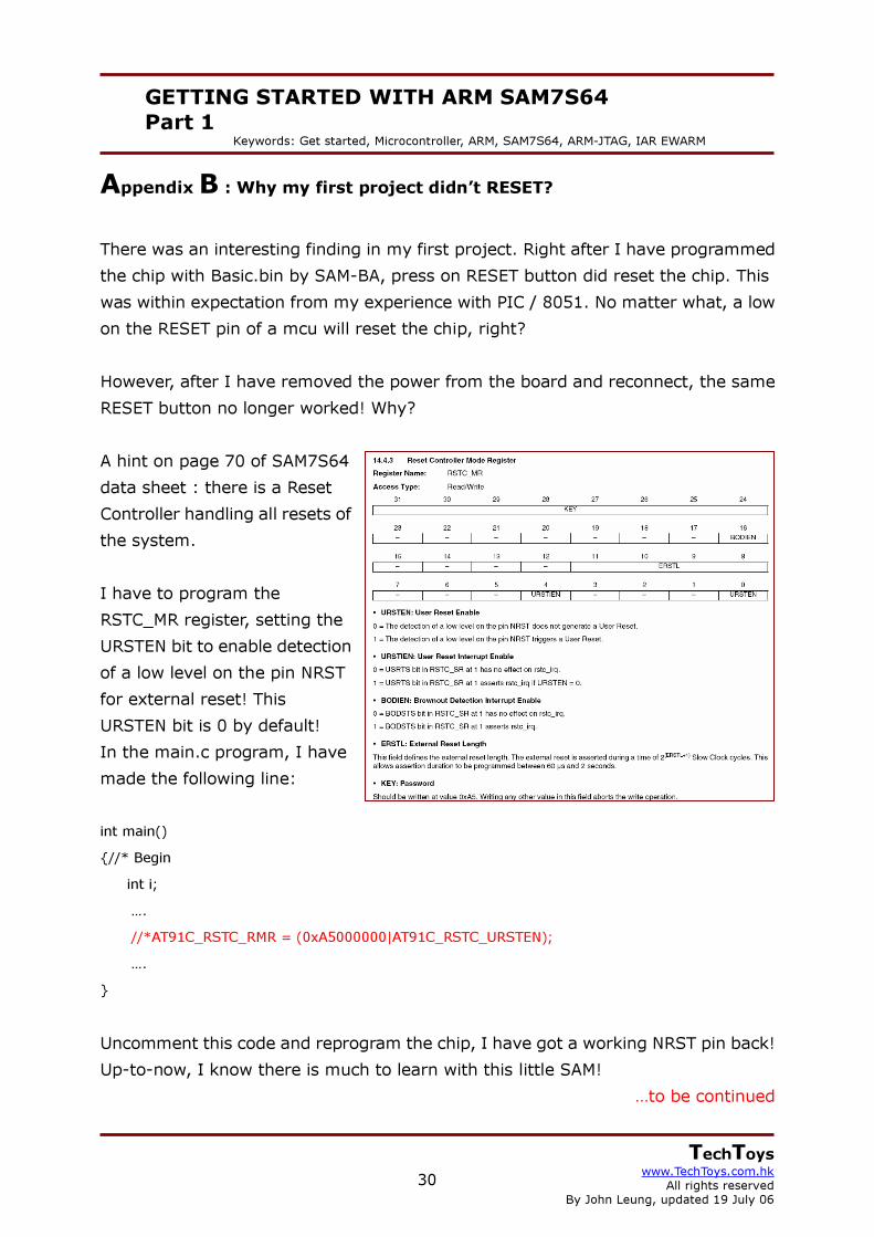
Appendix B : Why my first project didn’t RESET? There was an interesting finding in my first project. Right after I have programmed the chip with Basic.bin by SAM-BA, press on RESET button did reset the chip. This was within expectation from my experience with PIC / 8051. No matter what, a low on the RESET pin of a mcu will reset the chip, right? However, after I have removed the power from the board and reconnect, the same RESET button no longer worked! Why? A hint on page 70 of SAM7S64 data sheet : there is a Reset Controller handling all resets of the system. I have to program the RSTC_MR register, setting the URSTEN bit to enable detection of a low level on the pin NRST for external reset! This URSTEN bit is 0 by default! In the main.c program, I have made the following line: int main() {//* Begin int i;
…. //*AT91C_RSTC_RMR = (0xA5000000|AT91C_RSTC_URSTEN); ….
} Uncomment this code and reprogram the chip, I have got a working NRST pin back! Up-to-now, I know there is much to learn with this little SAM!
…to be continued